

digicon catrax automatic plus Product Manual
Product Manual


Copyright– Digicon S.A.
Controle Eletrônico para Mecânica – 2014
All rights reserved. No part of this publication may be reproduced, transmitted,
transcribed, stored in a retrieval system, translated into any language or computer
language in any electronic, magnetic, optical, chemical, manual way, or otherwise,
without the express written permission from Digicon S.A.
Manual code: 069.31.237
English - Revision: 03
This manual was elaborated by: Digicon S.A. Controle Eletrônico para Mecânica
Documentation Sector - EDS

Contents
05
06
06
07
09
10
10
11
11
12
14
14
14
15
16
17
17
18
18
19
19
20
23
24
24
24
25
25
26
26
26
28
29
30
31
31
32
33
35
1. Important instructions ..........................................................................
2.
Orientations ........................................................................................
3. Introduction ........................................................................................
4. Features of Catrax Automatic Plus ..........................................................
4.1. Catrax Automatic Plus operation ..........................................................
5. Installing/Assembling Catrax Automatic Plus ............................................
5.1. Unboxing .........................................................................................
5.2. floor drilling ......................................................................................
5.3. Column fixation .................................................................................
5.4. Assembling the arms .........................................................................
5.5. Access to Catrax Automatic Plus after assembly ......................................
5.5.1. Rear cover .....................................................................................
5.5.2. Front cover ....................................................................................
5.5.3. Column cover .................................................................................
5.6. Connection to power network ..............................................................
6. Installing/assembling optional items .......................................................
6.1. Collecting box kit ...............................................................................
6.1.1. Connection of collecting box kit to control board ...................................
6.2. Pictogram Kit ....................................................................................
6.3. Power supply ....................................................................................
6.4. Electromechanical counter kit ..............................................................
6.5. Control board ....................................................................................
6.5.1. Inputs ...........................................................................................
6.5.2. Outputs .........................................................................................
6.5.2.1 Return signal ................................................................................
6.5.2.2 Electromagnets .............................................................................
6.5.2.3. Sound alarm ................................................................................
6.5.2.4. Connection scheme ......................................................................
6.5.2.5. Pictogram ...................................................................................
6.5.2.6. Pictogram's connections ................................................................
6.5.3. Configuration of control board ..........................................................
6.6. Anti-panic system ..............................................................................
6.6.1. Assembling the arms .......................................................................
6.6.2. Maintenance test ............................................................................
7. Maintenance ........................................................................................
7.1. Preventive and corrective routine maintenance ......................................
7.2. Defects and possible causes ................................................................
8. Technical characteristics ........................................................................
9. Warranty and technical assistance ..........................................................
05
1. mportant nstructionsI i
You can see, below, the symbols that will appear in this manual,
signaling important moments. It is essential to pay attention to them.
TIP: Indicates something Digicon considers important.
CAUTION: Indicates a moment of extreme caution when
handling the equipment/product
ATTENTION: Indicates a moment when your observation
skills should be extremely productive.
INFORMATION: Presents interesting facts about the
purchased product.
QR CODE: Presents additional information or links
with more details about the presented text.

06
2. Orientations
Read the information and instructions of this manual carefully, before using the
product. This ensures the correct use of the equipment and maximum use of its
technical features as well as a prolonged service life.
This product does not present sealing against the rain, that is, it is designed to be
used indoors.
Keep this manual for future consultations.
Digicon reserves its right to alter its products at any moment to adapt them to more
recent technical advancements.
Digicon maintains its right to alter the information contained in this manual without
previous notice.
Digicon does not provide any contractual warranty concerning the information in
this manual, and cannot be held responsible for errors it may contain and problems
due to its use.
The information contained in this manual is exclusive property of Digicon and is
protected by copyright laws.
This manual cannot be reproduced, photocopied or translated, in its entirety or in
part, into any kind of medium, without Digicon's written consent.
3. Introduction
Following a new technological concept focused on solidity and reliability and counting
with
innovative design elements, with variety of colors, lines, and curves, Digicon has
launched the line CATRAX Automatic Plus.
CATRAX Automatic Plus serves most technologies of access control currently available,
becoming the best option in the market for access control.
This manual presents a detailed description of the components and working of CATRAX
Automatic Plus.
To see our complete catalogue, visit www.digicon.com.br.
07
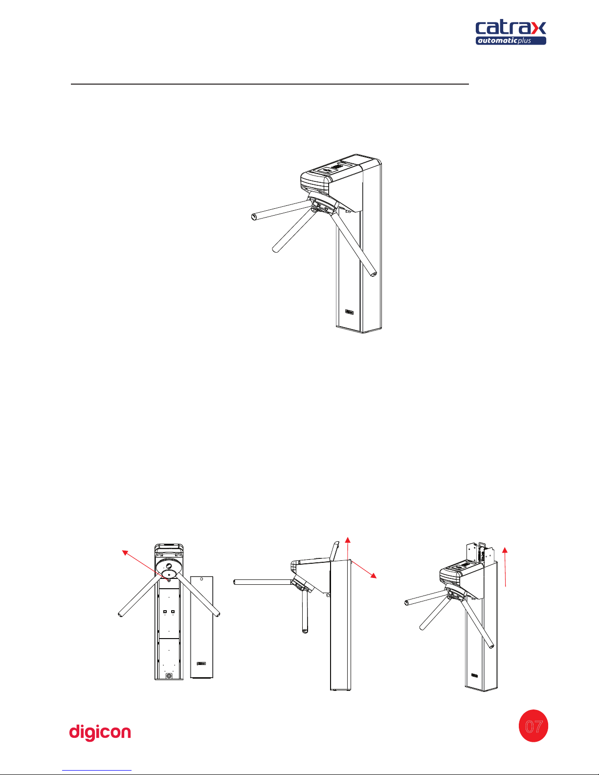
Lock
Open (key)
Raise the cover
Pull
4. Features of Automatic Master
CA
TRAX Automatic Plus, an access controller in the model mini turnstile (column
type), presents three bidirectional, equidistant arms at 120 degrees with brushed
stainless steel (AISI 304) finishing.
The column can present external finishing in brushed stainless steel (AISI 304) or
1020 carbon steel with electrostatic painting in black epoxy powder. It has reinforced
structure, fully rounded corners, and non-exposed screws, offering space and comfort
for any access control solution.
Aiming at facilitating assembly and maintenance, the column CATRAX Automatic Plus
presents a U-shaped internal support (mounting rack) with standard holes for the
fixation of additional electronic boards. Moreover, the clients, according to their needs,
can add additional holes. Access to the mounting rack is done through a key with
secret, whose removal and insertion are extremely easy.
08
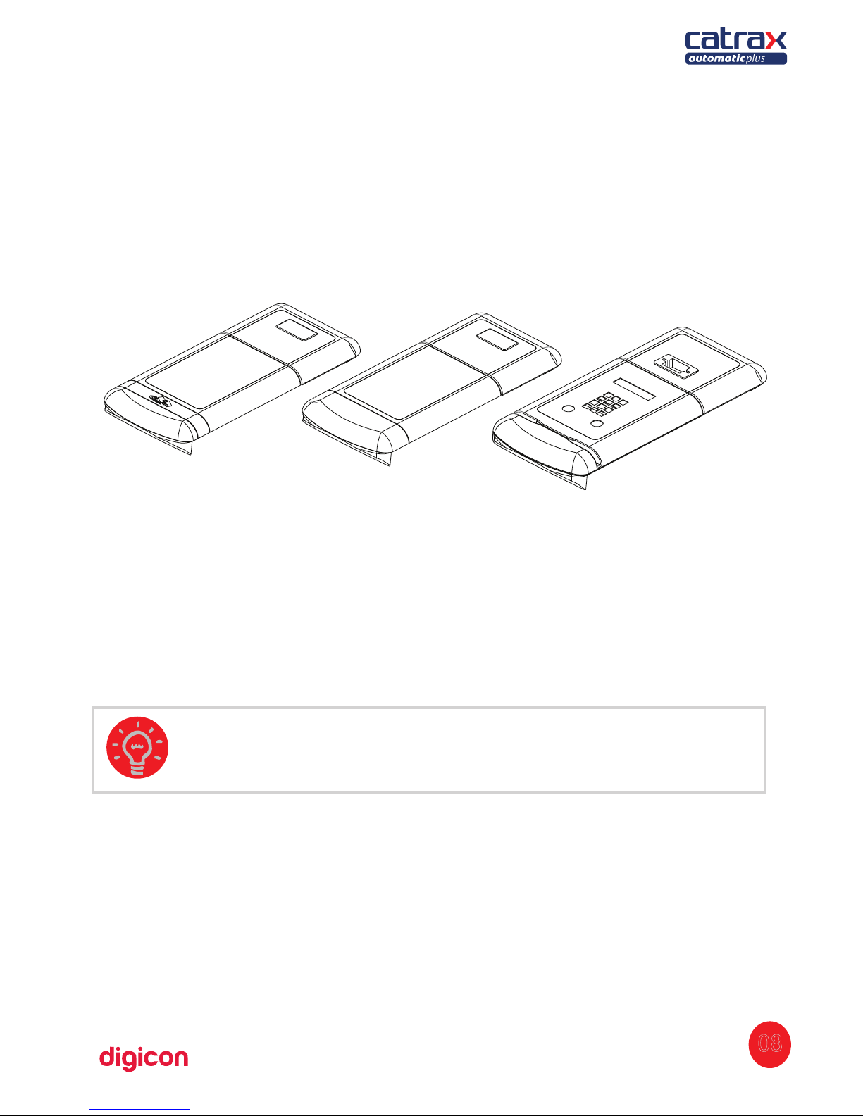
A plastic cover and a stainless steel sheet compose the upper panel. The cover, made
of injected plastic, can be purchased in the colors black, green, or burgundy; or in any
other color desired, on demand.
The upper cover in stainless steel allows easy configuration and low-cost
customization of the product. The sheet can also present slots for optional items, such
as pictogram, collecting box input, display kit (separate manual), or a combination of
these items. The following images show some of the options.
Besides compatibility with most available technologies, Digicon can provide the
following optional items: collecting kit with box, counter kit, power supply, MCA
board, and display kit
Contactless card reader
Flat
Card reader with slot
for barcode
TIP: To see details about the components' dimensions, see 8. Technical
characteristics.
09
4.1 Catrax Automatic Plus operation:
CATRAX Automatic Plus has bidirectional motorized turning with two 24 Vcc
electromagnets for activating the locks.
It also includes a microprocessor control board, where a signal enabling passage is
sent through one of the inputs, depending on the passage direction. If this signal is
recognized, the equipment will allow the turning of the arm of CATRAX Automatic Plus.
After half of the turning is complete (60 degrees), a 400 milliseconds returning signal
will be sent, informing the passage direction. After the signal, the arm cannot be
returned to the previous position.
Depending on the CATRAX Automatic Plus model and configuration, if the passage is
forced without the enabling signal, an electromagnet will be activated to prevent turn.
In addition, the equipment can emit a signal for a sound alarm and/or the exhibition of
a red X on the upper panel display (models with pictogram). In this case, a return
signal will be sent, indicating that the turnstile was forced, informing the direction of
turn.
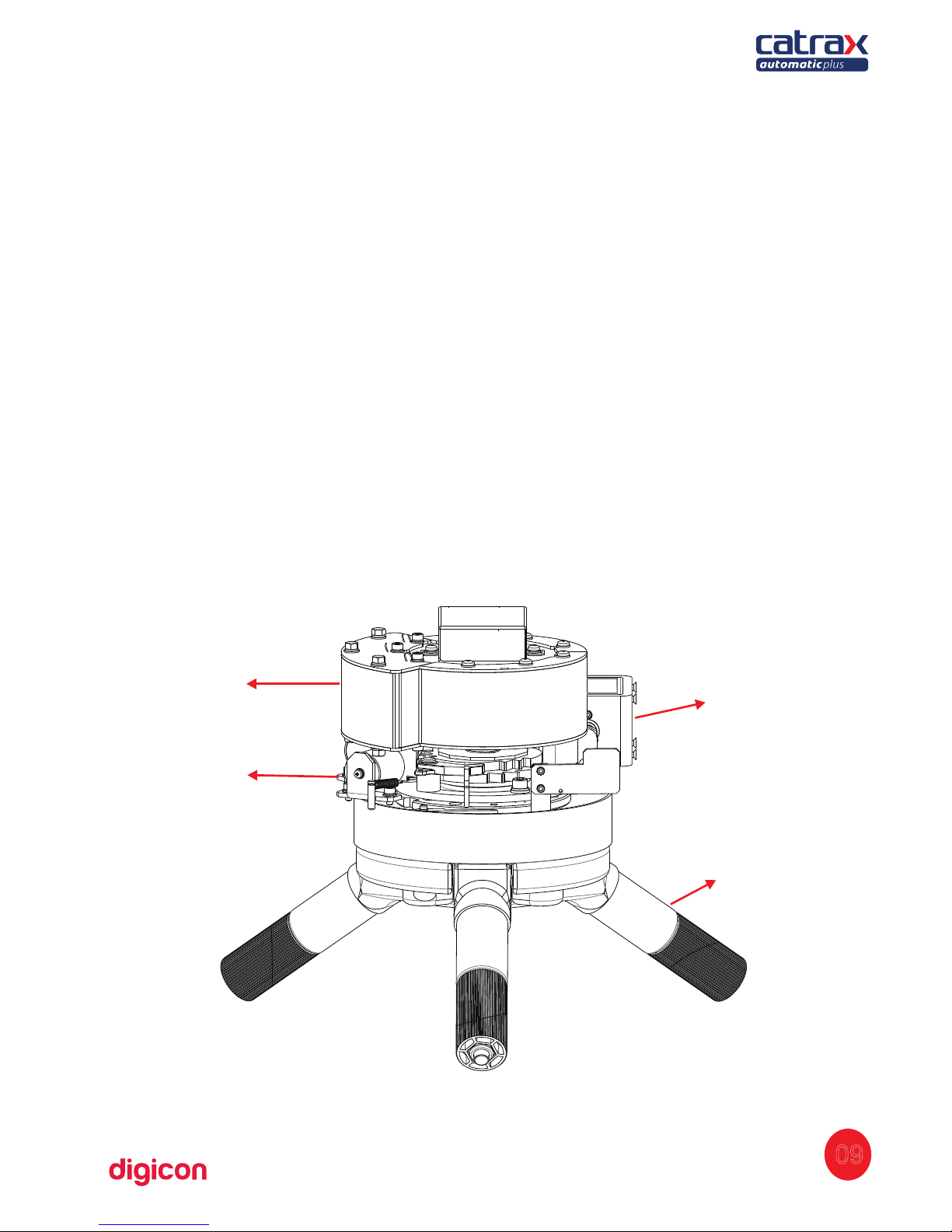
The image below shows the operation mechanism of CATRAX Automatic Plus.
Mini arm
Arn-drop
solenoid
(BQC)
Locks
Engine
Bidirectional arms:
- From left right
- From right to left
10
As the items inside the package can vary (depending on the client's requests), it is
important to perform a cautious visual inspection before installing and assembling the
turnstile. A checklist that works as a guide during inspection accompanies all Digicon
packages.
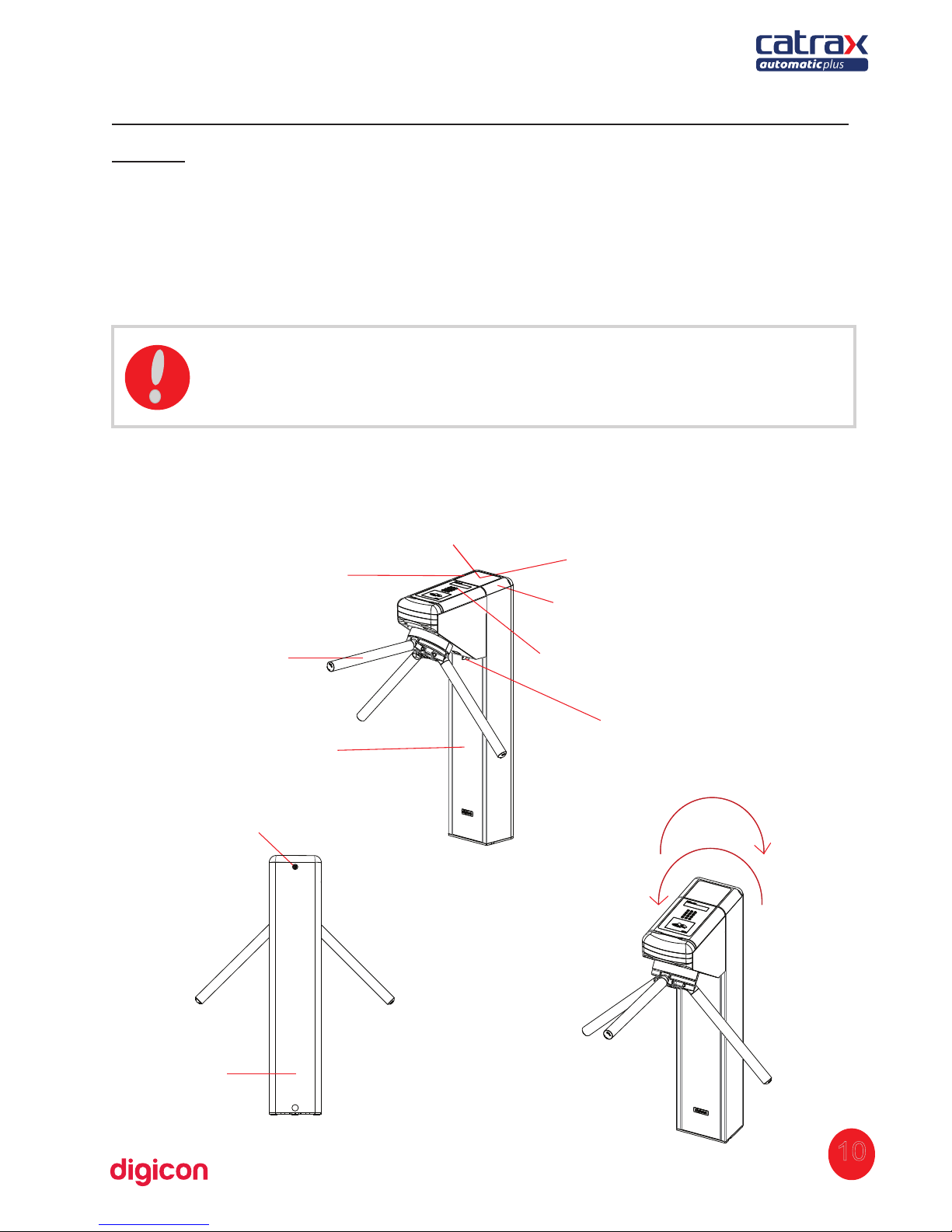
See below the parts that can compose CATRAX Automatic Plus:
ATTENTION: To avoid losses, the screws and the wrenches used for
assembling the CATRAX Automatic Plus are attached to the box containing
the arms. Before discarding the packing materials (cardboard and plastics),
make sure all the items in the checklist are accounted for.
Plastic cover kit
Arm
Lock to access the column
Column door
Upper pictogram
kit (optional)
Collecting box
kit (optional)
Stainless steel
sheet (rear cover)
Stainless steel
sheet (front cover)
Lock to access
the column’s rack
Lock to access the
cover for the pasage
of cables
5.Installing/Assembling Catrax Automatic
Plus
5.1. Unboxing
11
5.2 Floor drilling:
Before installing CATRAX Automatic Plus, check:
1. The place chosen for the installation.
2. If there is a power source or electric socket nearby (ducts for connection).
3. If the place chosen is adequate for the installation of the access controller (indoors).
4. If there will be enough space (minimum 5 cm) between the rear of the CATRAX
Automatic Plus column and the wall. This space is important in order to provide access
to the upper panel and plug's locks for the cables passage.
5. If there will be enough space for the arms after CATRAX Automatic Plus is
assembled.
6. If the floor is in conditions to receive anchor bolts (minimum of 4 cm of FCK15 M.P.A.
concrete or equivalent).
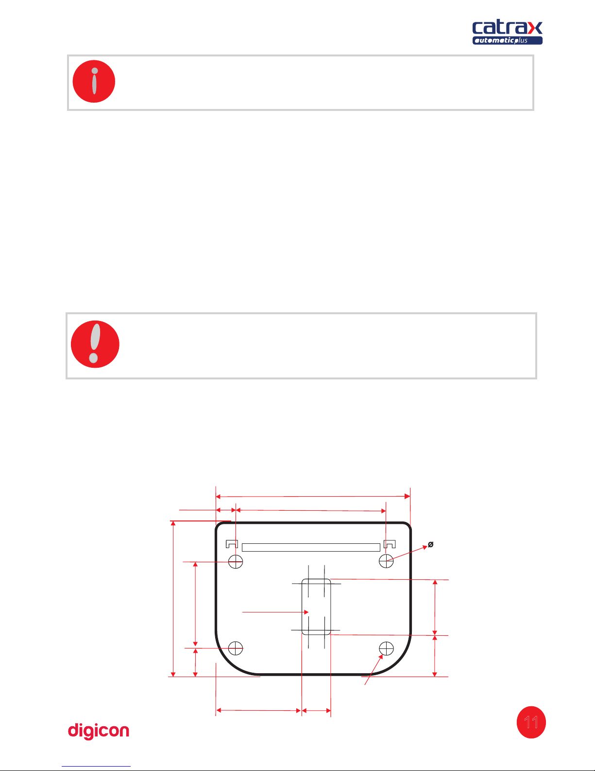
5.3 Column fixation:
To fix the column to the floor, observe the following steps and the indicated images:
1.
rill the floor with 3/8” drills (then use a 12mm or the ½” drill). Make four externalD
holes, according to the measures indicated in the image below:
INFORMATION: Besides the items mentioned above, CATRAX Automatic
Plus can be provided with counter kit and display kit.
12,5 (4x) (0,492")
210 (8,267")
170 (6,692")
78
(3,070")
36
(1,417")
Cables’ output
92,5
(3,641")
32
(1,259")
20
(0,787")
Fixing perforation
51
(2,007)
79,5
(3,129")
160
(6,299")
ATTENTION: Since the CATRAX Automatic Plus's installation requires
floor drilling, it is important that the location be chosen carefully.
12
5.4 Montagem dos braços e tampas:
I :NFORMATION
2. Clean the holes, removing any debris from drilling.
3. Place the external part of the bolts in the holes. Leave about 25mm of the bolt out of
the hole.
4. Position the column and fasten it to the floor with the four screws that accompany
the bolts. Use a flex-head socket wrench with ¾'' or an articulated socket wrench.
After drilling the floor and assembling the column, it is possible to assemble the arms
and plastic covers.
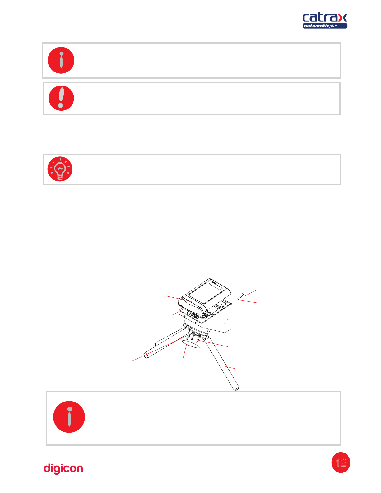
The image below shows the specific parts of CATRAX Automatic Plus's arms and upper
frontal cover with assembling instructions.
Arm
Screw M3x8
Flat washer M3
Screwa access cover
Allen M6x20 Screw
Spring washer M6
INFORMATION: n the central slot, destined to the passage of cables, it isI
necessary to measure the cables according to the opening's size.
TIP: As an optional item, Digicon can provide a steel template for fixing
CATRAX Automatic Plus, containing the exact demarcations of the
necessary holes.
TIP: We recommend the bolts by the brand Tecnart, model AF38110,
3/8x4''
Screw M3x16
Upper co
ver plastic
- The cover for accessing the screws is fitted into place, so pressure it to
open or close it.
- To assemble the arms of CATRAX Automatic Plus, use an Allen n. 8
wrench.
 Loading...