

Page 1
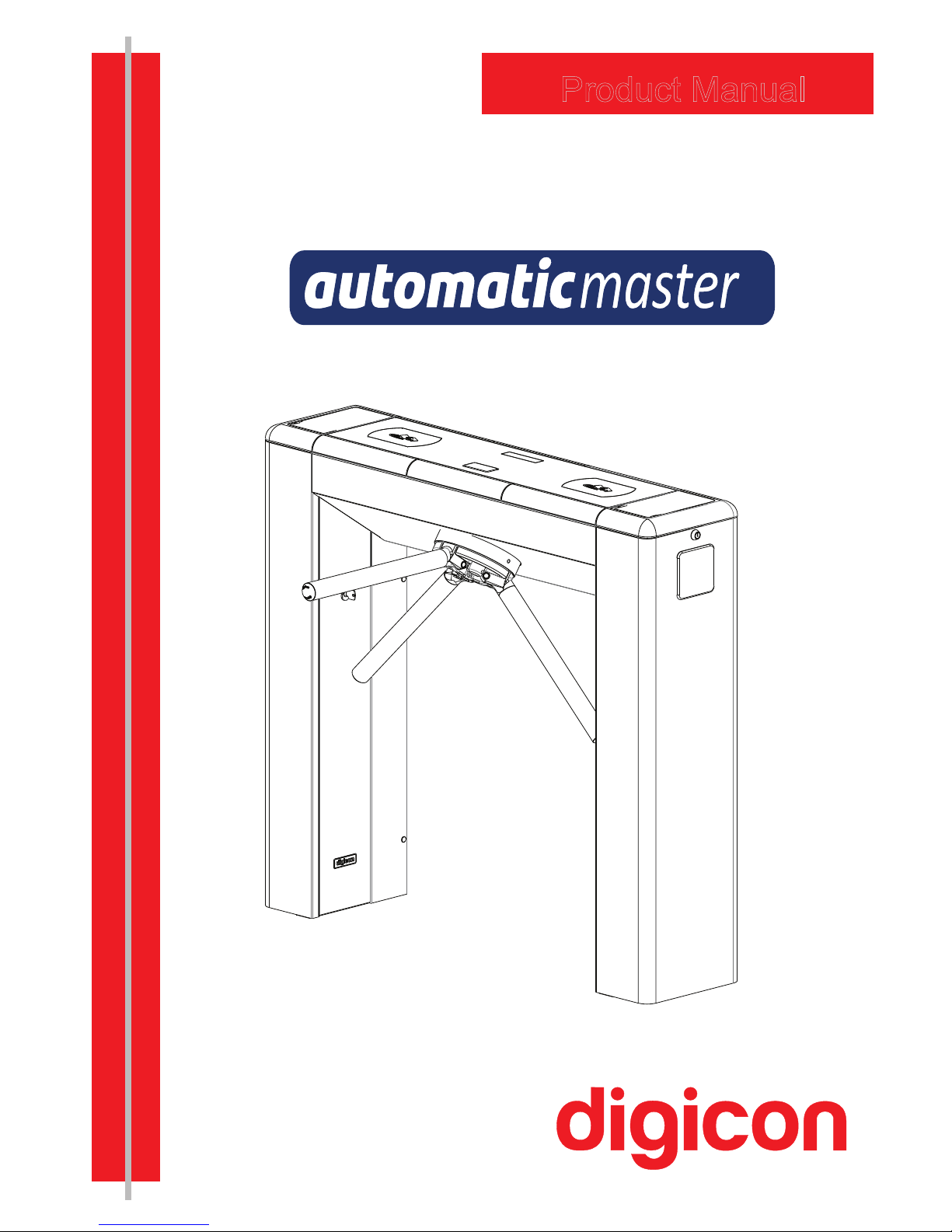
Product Manual
Page 2

Page 3

Copyright– Digicon S.A.
Electronic Control for Mechanics – 2014
All rights reserved. No part of this publication may be reproduced, transmitted,
transcribed, stored in a retrieval system, translated into any language or computer
language in any electronic, magnetic, optical, chemical, manual way, or otherwise,
without the express written permission from Digicon S.A.
Manual code: 069.31.202
English - Revision: 02
This manual was elaborated by: Digicon S.A. Controle Eletrônico para Mecânica
Documentation Sector - EDS
Page 4

1. mportant InstructionsI ...................................................
2. Orientations ..................................................................
3. Introduction ..................................................................
4. Features of Automatic Master ..........................................
4.1 Automatic Master Operation ...........................................
5. Installing/Assembling .....................................................
5.1 Unboxing ....................................................................
5.2 Floor drilling and column fixation ...................................
5.3 Assembling the arms ...................................................
5.4 Access to Automatic Master after assembly ......................
5.5 Connection to power network ........................................
6.Installing/Assembling operational items .............................
6.1 Rear closure kit ...........................................................
6.2 Collecting box kit .........................................................
6.2.1 Connection of collecting box kit to control board ............
6.3 Oper
ational pictogram kit ..............................................
6.4 Orientation pictogram kit ..............................................
6.5 Power Supply ..............................................................
6.6 Electromechanical counter kit ........................................
6.7 Control Board ..............................................................
6.7.1 Inputs .....................................................................
6.7.1.1 Return signals ........................................................
6.7.1.2 Electromagnets ......................................................
6.7.1.3 Sound alarm ..........................................................
6.7.1.4 Connetcion scheme ................................................
6.7.1.5 Pictogram .............................................................
6.7.2 Output ....................................................................
6.7.3 Control board configuration ........................................
6.7.4 Turnstile interface .....................................................
6.8 Anti-Panic system ........................................................
6.8.1 Maintenance test .......................................................
7. Maintenance .................................................................
7.1 Preventive and corrective rountine maintenance ..............
7.2 Solving problems .........................................................
8. Technical characteristcs ..................................................
9. Warranty and technical assistance ....................................
Contents
05
06
06
07
08
09
09
10
11
12
14
15
15
16
16
17
17
18
18
19
21
22
22
23
23
24
24
24
26
32
33
34
34
35
36
38
Page 5
05
1. mportant nstructionsI i
You can see, below, the symbols that will appear in this manual,
signaling important moments. It is essential to pay attention to them.
TIP: Indicates something Digicon considers important.
CAUTION: Indicates a moment of extreme caution when
handling the equipment/product
ATTENTION: Indicates a moment when your observation
skills should be extremely productive.
INFORMATION: Presents interesting facts about the
purchased product.
QR CODE: Presents additional information or links
with more details about the presented text.
Page 6

Following a new technological concept focused on solidity and reliability and counting
with innovative design elements, with color variety and widely curved lines, Digicon has
launched the line Automatic Master.
Automatic Master serves most technologies of access control currently available,
becoming the best option in the market for access control.
This manual presents a detailed description of the components and working of
Automatic Master. To see our complete catalogue, visit
www.digicon.com.br.
06
2. Orientations
Read the information and instructions of this manual carefully, before using the
product. This ensures the correct use of the equipment and maximum use of its
technical features as well as a prolonged service life.
This product does not present sealing against the rain, that is, it is designed to be
used indoors.
Keep this manual for future consultations.
Digicon reserves its right to alter its products at any moment to adapt them to more
recent technical advancements.
Digicon maintains its right to alter the information contained in this manual without
previous
notice.
Digicon does not provide any contractual warranty concerning the information in this
manual, and cannot be held responsible for errors it may contain and problems due
to its use.
The information contained in this manual is exclusive property of Digicon and is
protected by copyright laws.
This manual cannot be reproduced, photocopied or translated, in its entirety or in
part, into any kind of medium, without Digicon's written consent.
3. Introduction
Page 7
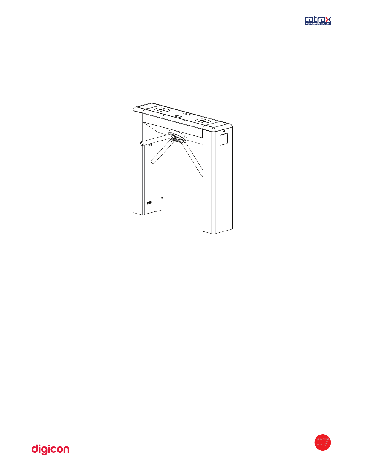
The structure of Automatic Master can present external finishing in brushed stainless
steel (AISI 304) or 1020 carbon steel with electrostatic painting in black epoxy powder.
It has reinforced structure, fully rounded corners, and non-exposed screws, offering
space and comfort for any access control solution. Aiming at facilitating assembly and
maintenance, the column Automatic Master presents a U-shaped internal support
(mounting rack) with standard holes for the fixation of additional electronic boards.
Moreover, the clients, according to their needs, can add additional holes. Access to the
mounting rack is done through a key with secret, whose removal and insertion are
extremely easy.
A plastic cover and a stainless steel sheet compose the upper panel. The cover, made of
injected plastic, can be purchased in the colors green, burgundy, or black or in any
other color desired, on demand.
The upper cover in stainless steel allows easy configuration and low-cost customization
of the product. The sheet can also present slots for optional items, such as operational
pictogram (on top), orientation pictogram (side), collecting box inlet, display kit or a
combination of these items.
07
4. Features of Automatic Master
Automatic Master, an access controller in the model blockage, presents three
bidirectional, equidistant arms at 120 degrees with brushed stainless steel (AISI
304) finishing.
Page 8

Besides compatibility with most available technologies, Digicon can provide the
following optional items: collecting kit with box, pictogram kit, counter kit, power
supply, power supply, control board, and display kit. These items are described in
details in item 6. Installing/Assembling optional items.
TIP: To see details about the dimensions of Automatic Master's items,
see item 8. Technical characteristics.
4.1 Automatic Master operation
A Automatic Master has bidirectional motorized turning with two 24 Vcc
electromagnets for activating the locks.
It also includes a microprocessor control
board,
where a signal enabling passage is sent through one of the inputs, depending on
the passage direction. If this signal is recognized, the equipment will allow the turning
of the arm of Automatic Master. After half of the turning is complete (60 degrees), a 400
milliseconds returning signal will be sent, informing the passage direction. After the
signal, the arm cannot be returned to the previous position.
Depending on the Automatic Master model and configuration, if the passage is forced
without the enabling signal, an electromagnet will be activated to prevent turn. In
addition, the equipment can emit a signal for a sound alarm and/or the exhibition of a
red X on the upper panel display (models with pictogram). In this case, a return signal
will be sent, indicating that the turnstile was forced, informing the direction of turn.
The image below shows the operation mechanism of Automatic Master.
08
SENSORS
LOCKS
SOLENOID
ARM
Page 9
5. Installing/Assembling
5.1 Unboxing
As the items inside the package can vary (depending on the client's requests), it is
important to perform a cautious visual inspection before installing and assembling the
turnstile. A checklist that works as a guide during inspection accompanies all Digicon
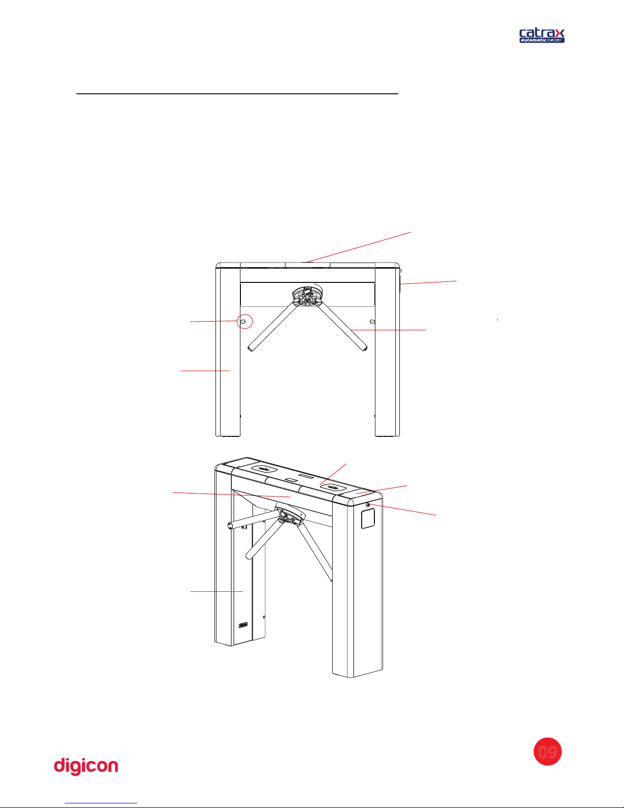
packages. See below the parts that can compose Automatic Master:
OPERATIONAL PICTOGRAM
(OPTIONAL)
LOCK FORACCESSING
THE COLUMN
ORIENTACION PICTOGRAM
(OPTIONAL)
COLUMN
ARM
CENTRAL COVER
EXTERNAL COVER
LOCK FOR RACK AND COLUMN
DIGITAL COUNTER
(OPTIONAL)
COLUMN DOOR
09
Page 10

5
209
30
80
35
941
1001
12,5 (4X)
5.2 Floor drilling and column fixation
Before installing Automatic Master, check:
1. if the floor has conditions to receive anchor bolts (at least 4cm of FCK15 M.P.A.
concrete or equivalent)
2. If there is a power source or electric socket nearby (ducts for connection).
3. If the place chosen is adequate for the installation of the access controller (indoors).
4. If access to the Automatic Master's locks is clear.
5. If there will be enough space for the arms after Automatic Master is assembled.
ATTENTION: For
more details on the dimensions of Automatic Master's
components, see item 8. Technical characteristics.
Once you observe these recommendations, proceed to the installation:
1. rill the floor with 3/8” drills (then use a 12mm or the ½” drill). Make two holes inD
each column of Automatic Master, according to the measures indicated in the image
below:
2. Clean the holes, removing any debris from drilling.
3.
Place the external part of the bolts in the holes. Leave about 25mm of the bolt out of
the hole.
TIP: We reccomend anchor bolts by Tecnart, model AF38110, 3/8x4”.
4. Position the column and fasten it to the floor with the four screws that accompany the
bolts. Use a flex-head socket wrench with ¾'' or an articulated socket wrench.
10
Page 11
5.3 Assembling the arms
After positioning and aligning the turnstile in its operation place, it's time to assemble
the arms. Make sure that you have all the necessary items and that the turnstile is
turned off, once you will have to remove the bowl to screw in the arms.
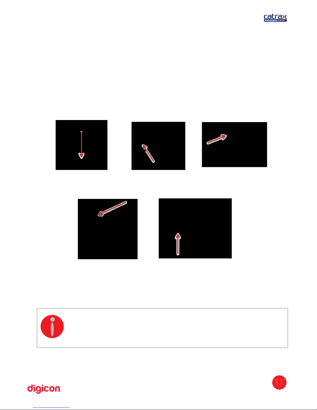
The arms are provided disassembled. To assemble them, observe the following
instructions.
The wrench used for assembling the arms is an Allen n.8 and the screws must be
fastened to the maximum to ensure good fixation. All three arms must be fixed in the
same upper central point.
Repeat the operation on the three arms and make sure all arms are well fixed.
INFORMATION:
- The cover for accessing the screws is fitted into place, so pressure it to
open or close it.
- To assemble the arms of Automatic Master, use an Allen n. 8 wrench.
11
1 Let the mini arm drop
st
2 Ma ke sure the mi ni
n d
arm's plastic part is fitted into
the steel part.
3 Fit the stainless steel
rd
arm in the mini arm
4 Fixate the screw inside the
th
mini arm using an Allen n.8 wrench
5
Put the arm back into
th
its normal position
Page 12
5.4 Accessing the turnstile after assembly
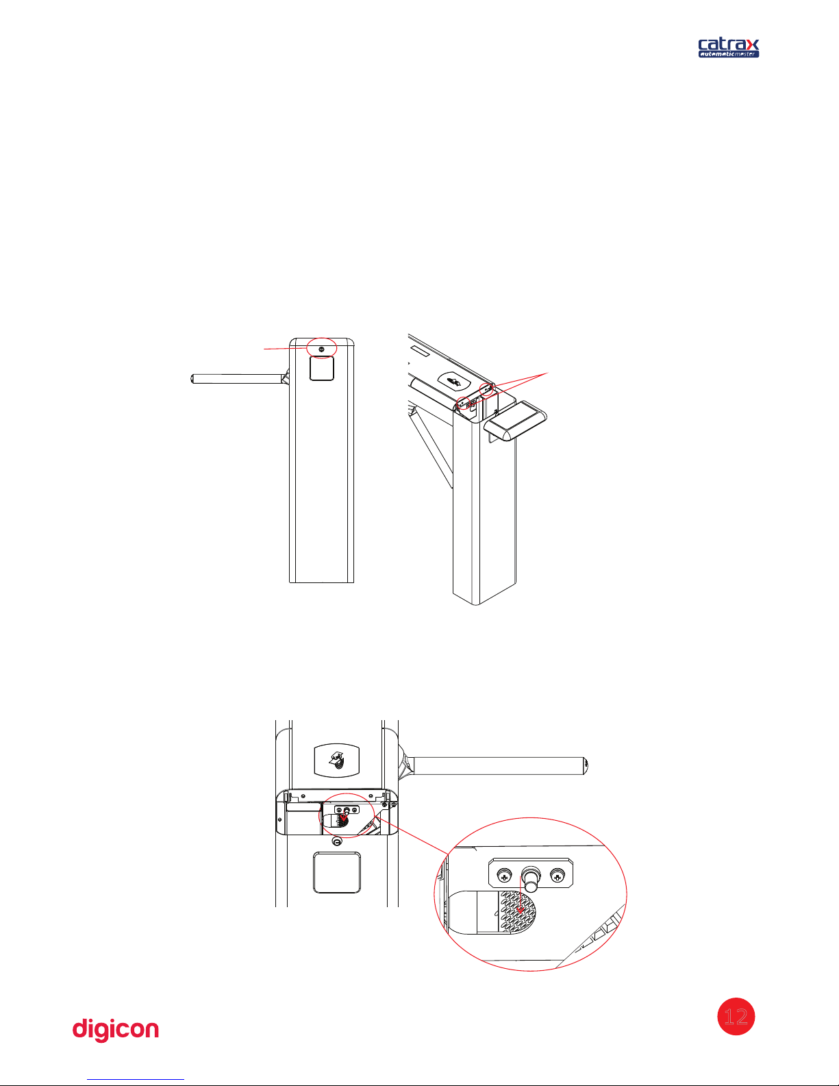
After Automatic Master is installed and assembled, access to the interior of the
equipment can be done with the key that accompanies the equipment, in three ways:
external covers, central cover, or column door.
See now the instructions for opening Automatic Master after assembly:
1. Unlock the two extremities of the Automatic Master, using the key provided
alongside the product. Remove the external covers, which are pressed into place. The
covers feature small internal couplings that support them in the column during
operation, as can be seen in the image to the right.
LOCK
FIT THE PINS OF THE
EXTERNAL COVER
2. Before opening the central cover, deactivate the security pins located on each side
of
the cover.
12
Page 13
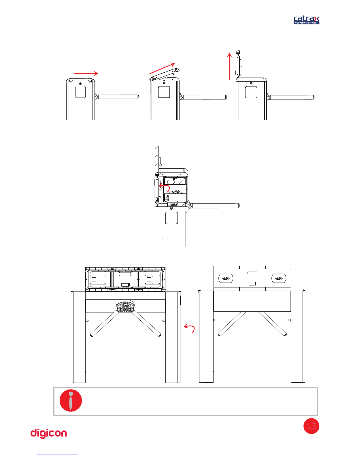
3. Open the cover according to the following images:
Note that the equipment structure contains a device that maintains the cover in the
vertical position (see detail).
4. The following image shows Automatic Master with all covers open.
INFORMATION: To access the column door, remove the external
cover on the appropriate side.
13
Page 14
5.5 Connection to power network
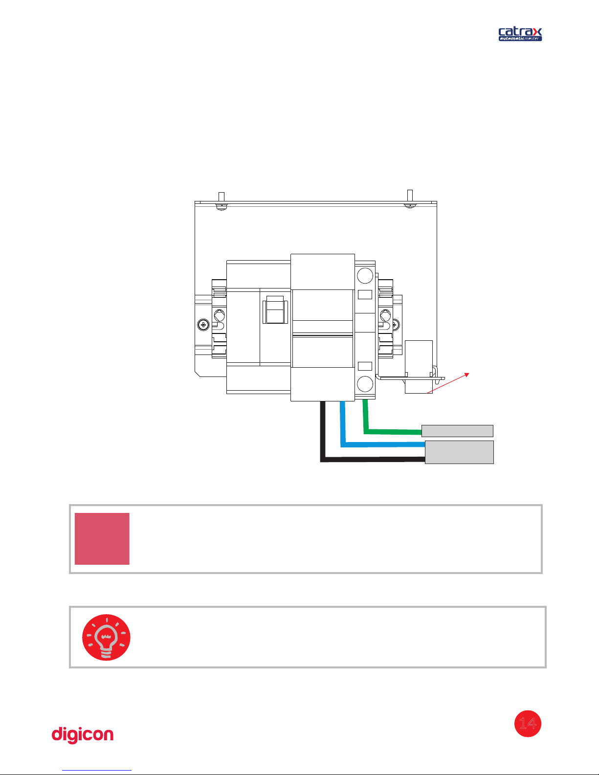
The Turnstile is powered by a 24 Vcc supply (located inside the turnstile). The
power supply can be of 100 to 240 Vca. Digicon recommends the regulation NBR
5410 as reference to the equipment's electrical connections. In one of its columns,
the turnstile has circuit breakers in its columns where the power cables (electrical
supply) and the ground wire must be connected.
Ground wire
Electric network
CAUTION: Electric connections must be performed by qualified
professionals.
TIP: We recommend that you use a good quality AC cable and ground wire
and with compatible dimensions to the distance until the switchboard.
14
Input for
data cables
Page 15
6.Installing/assembling optional
items
Automatic Master is compatible with most access control technologies in the market
today; however, Digicon offers a range of optional items that allow enhancing and
matching the equipment's performance to the client's needs. See the description of
each of these items:
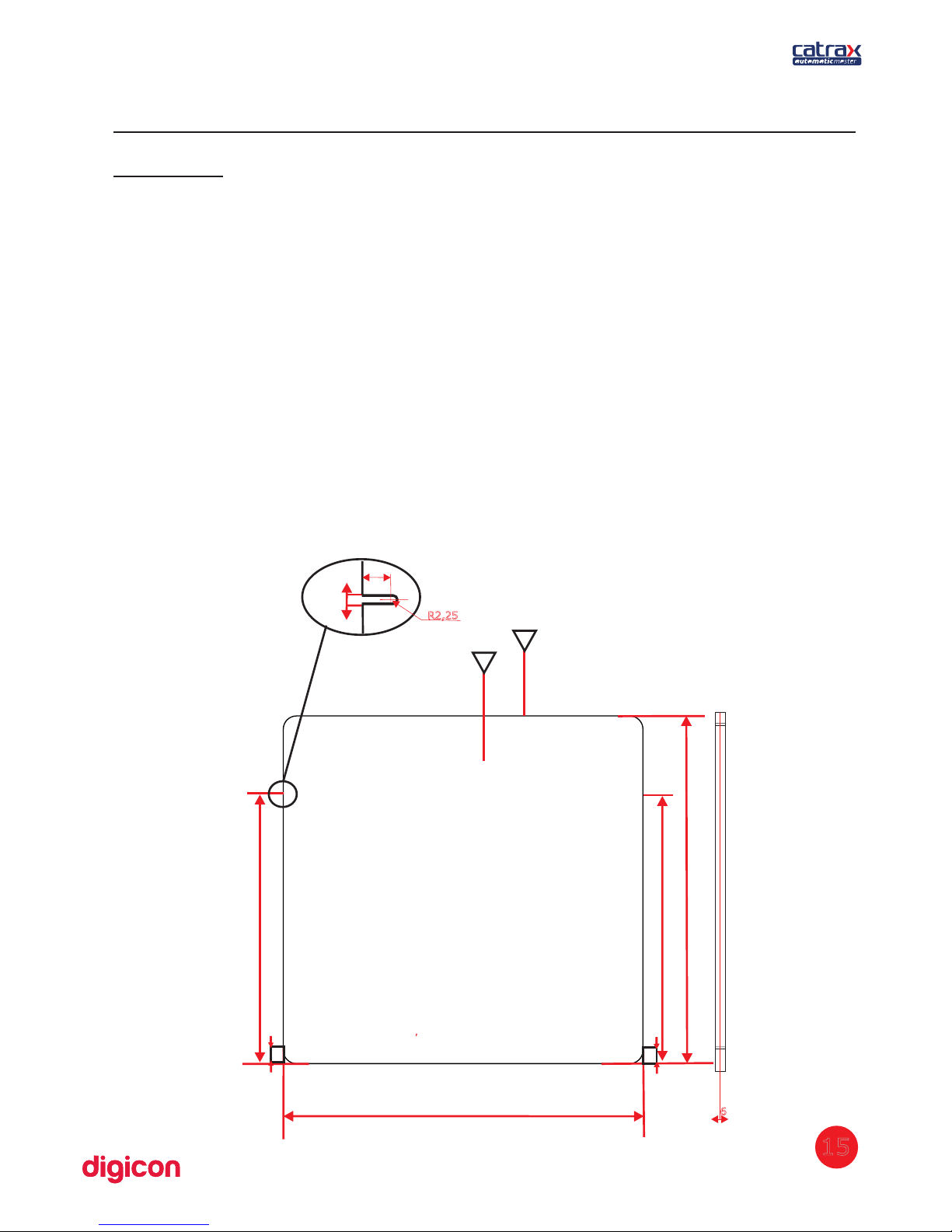
6.1 Rear closure kit
Automatic Master can be provided with a panel to close the rear space between the
columns.
The sheet can be of 6 mm tempered glass, 6 mm acrylic, or and 1.2 mm
stainless steel, as the client sees fit. Besides closing the rear space, the panel allows
simple customization with low cost.
The rear closure kit is mounted has four fasteners that secure the sheet to the side
columns, as shown below:
15
35
784
598
598
750
A
B
35
3535
4,5
R2,25
8
6
Detail 4x
Page 16
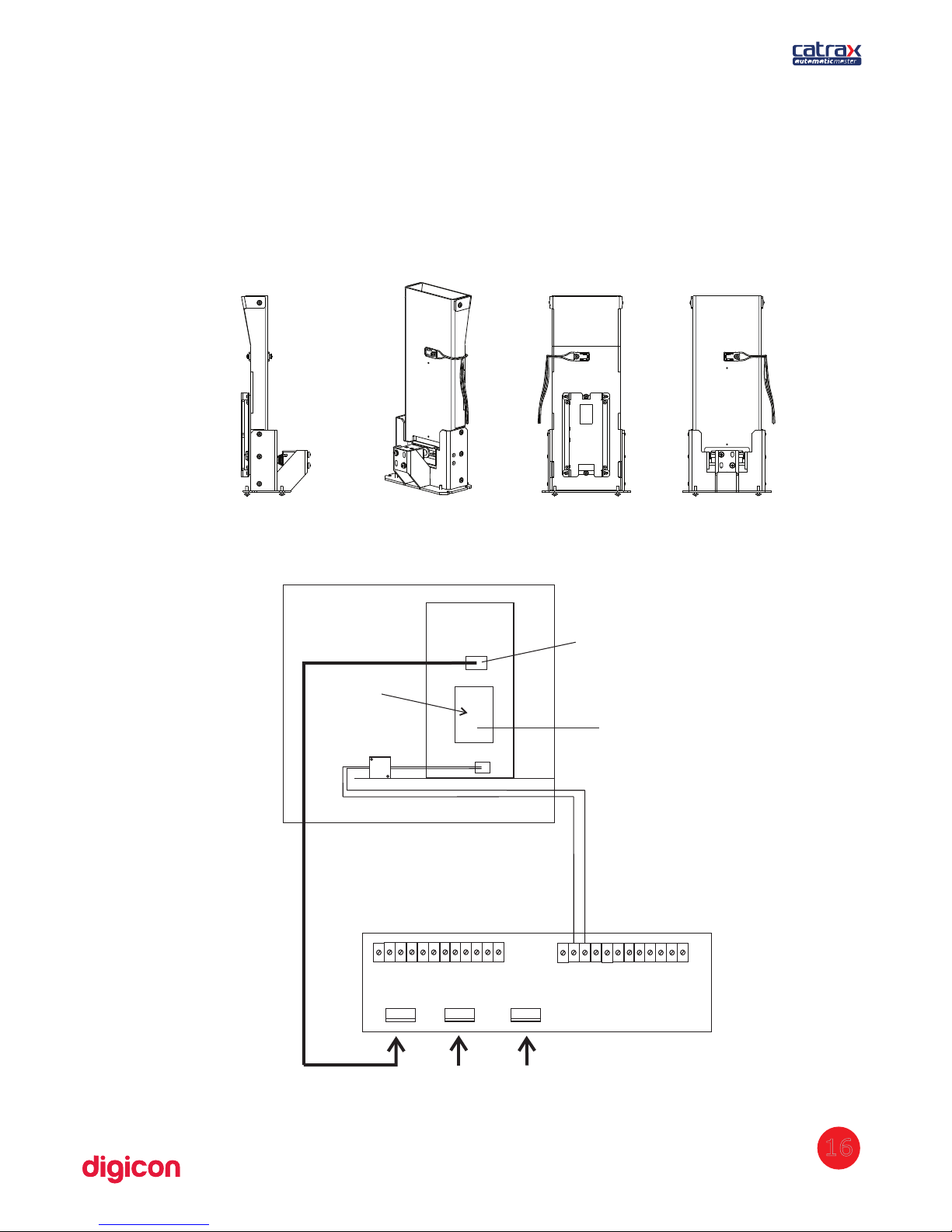
6.2 Collecting box kit
The collecting box kit has a device for collecting, retaining, and gathering cards or
badges. It is ideal for places with eventual visitors or users. The kit is composed of a
socket, a retention device activated by a solenoid, and a storage box. The image
below shows the items that accompany the collecting box kit:
6.2.1 Connection of collecting kit to control board
16
12 11
10
9
8
7
6
5
4
3
2
1 12 11
10
9
8
7
6
5
4
3
2
1
BOX SENSOR
ELECTROÍMAGNETS
TURNSTILE SENSORS
DIGICON CONTROL BOARD
INPUTS CN8
OUTPUTS CN9
- SOLENOID
+ SOLENOID
SOLENOIDE
Connection of
collecting kit
to control board
For access
control board
Sensor used for collecting
the card after 1.5 seconds
Page 17
INFORMATION:
- The box for cards is part of the kit and is positioned under the collecting
kit.
- The badge reader is not part of the kit.
TIP: To obtain information on the configuration of the collecting kit, see
item 6.7Control board.
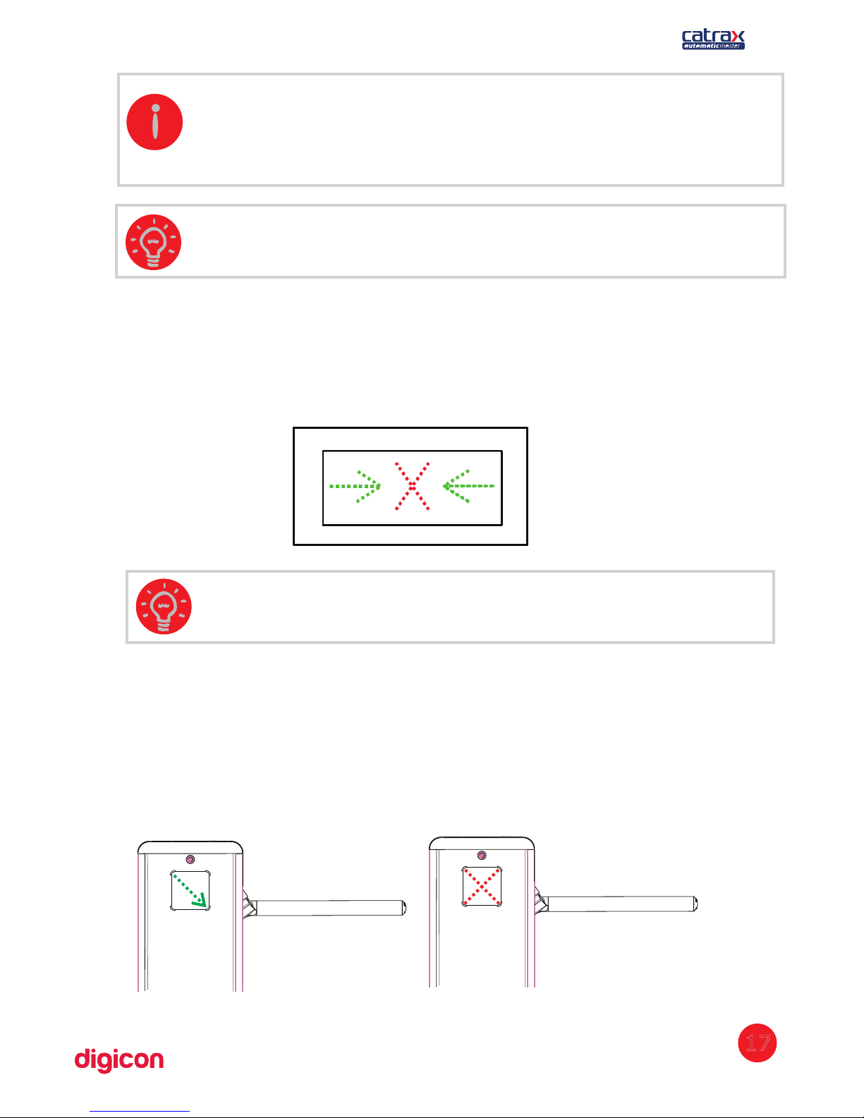
6.3 Operational Pictogram Kit
The operational pictogram kit visually signals the direction of passage (green arrows)
or the blocking (red X) on the upper part of Automatic Master.
TIP: To obtain information on the configuration of the pictogram, see
item 6.7 Control board.
6.4 Orientation pictogram kit
The orientation pictogram kit also visually signals the direction of passage (green
arrows) or the blocking (red X), but on the front/side part of Automatic Master.
17
Page 18
TIP: To obtain information on the configuration of the pictogram, see
item 6.7 Control board.
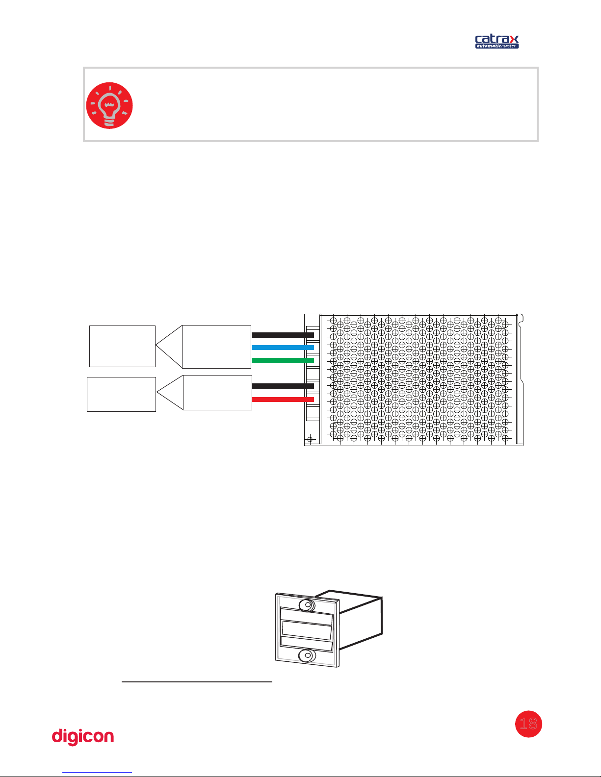
6.5 Power supply
Among the main advantages of this optional item, is its adaptation capability to the
voltage variations often found in installation sites – the input voltage can vary
between 100 and 240 Vca.
The supply's specific technical features, protections and dimensions were carefully
tested and approved in hostile temperature and environmental conditions, which
ensures the adequate power supply to the equipment's performance. Besides the
input and output voltages indicated in the image below, the supply has a shortcircuit and overheating protection.
PHASE
NEUTRAL
GROND WIRE
GND
24V / 3ADC
INPUT:
100 a
240 VAC
OUTPUT
6.6 Electromechanical counter kit
The counter kit presents six digits, from no return to zero, and is located on the
bowl
's upper part of the turnstile.
The counter presents pulse input, making it possible to detect turnstile rotations in
a given direction. The device is also capable of counting single pulses (as other
counters available on the market).
18
Technical characteristics:
Power supply: 24 Vcc - 5 Vcc (battery
eliminator) number of digits: 06 (no return to
zero)Digits size: 5 x 2 mm (height x width)
Page 19

6.7 Control Board
Automatic Master's control board was designed to meet most technologies of
access control terminals in the market. The controller have mechanical features
and layout perfectly suited for the Automatic Master's needs and it is one of the
best options for the equipment's operation.
The following images show the control board with its straps, connectors, and
dipswitch, as well as the location of the power supply and the control board in
Automatic Master.
CONNECTOR
CN8
CONNECTOR
CN9
Ds1
Ds2
The table below describes the functions of the control board's connectors:
19
Page 20

20
Signal Nome/Description
CN1 BOX SENSOR
1 LED anode
2 Box Signal
3 GND
4 GND
CN2 JTAG – Inner use
CN3 SERIAL RS - 232
2 TX
3 RX
5 GND
CN4 ENGINE
1 DATE +
2 DATE 3 GND_485
4 (+) 24V_EXT
5 GND
CN5 POWER – POWER SUPPLY
1 (+) 24V cd
2 GND
3 (+) 24V cd
CN6 TURNSTILE SENSORS
1 sensor 1 signal
2 LED 1 anode
3 sensor 2 signal
4 GND
5 LED 2 anode
CN7 AUDIO
1 SIGNAL
2 GND
Cn8 INPUTS
1 (+) vext1 (enables turn through voltage)
2 HAB1 (enables turn through dry contact – from right to left)
3 GND
4 Vext2 (enables turn through voltage)
5 HAB2 (enables turn through dry contact – from left to right)
6 GND
7 +24V c (available to auxiliary – maximum 500 mA)d
8 Vext3 (enables turn through voltage)
9 BQC (activates anti-panic system)
10 GND
11 Output for yellow pictogram
12 NC
13 NO or NC contact (bob return)
14 C Contact (bob return)
15 NO or NC contact (BOC return)
16 contact C (BOC return)
Page 21
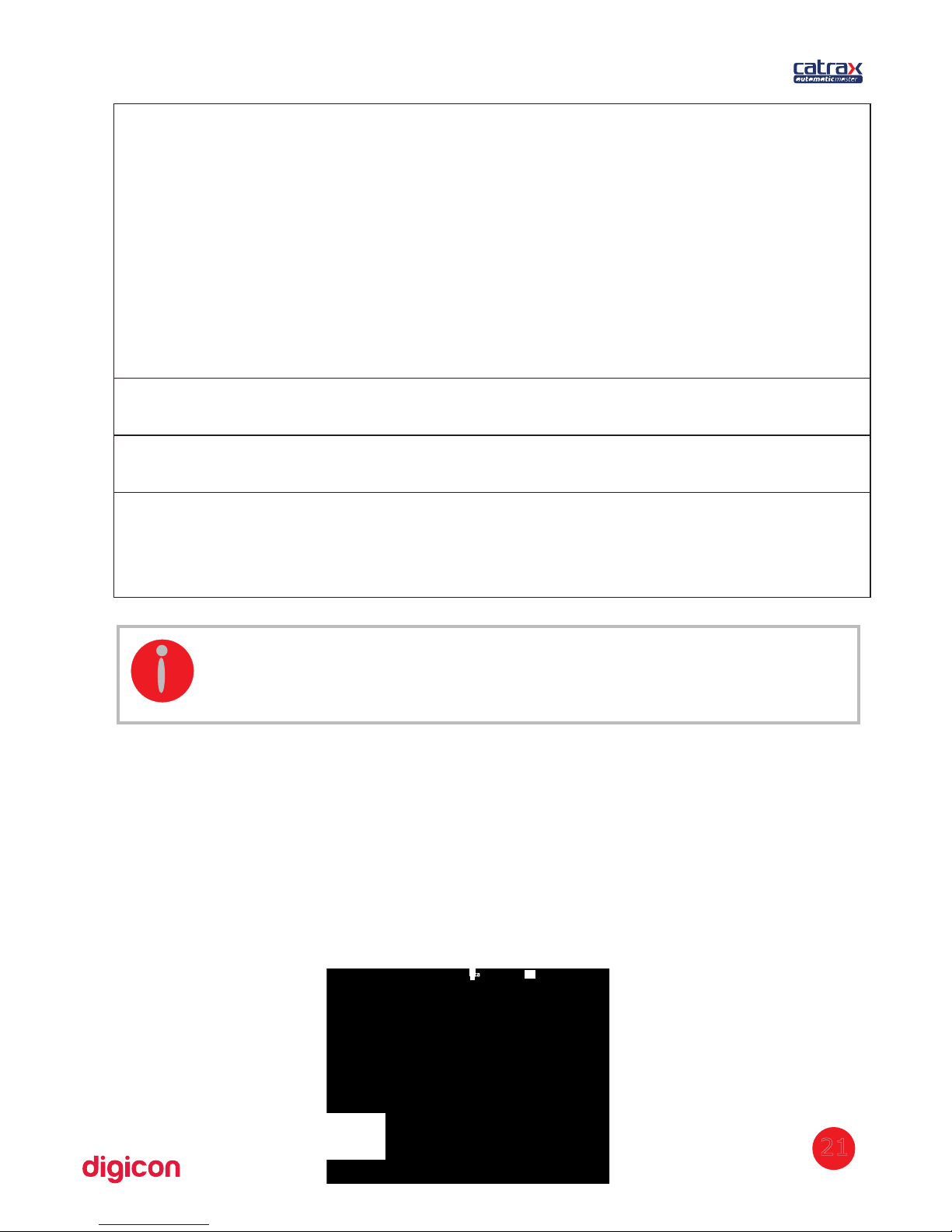
CN9 OUTPUTS
1 NO or NC Contact (HAB1 return)
2 Contact C (HAB1 return)
3 NO or NC Contact (HAB2 return)
4 Contact C (HAB2 return)
5 Output for indicative X (open collector NPN – maximum 500 mA)
orange wire
6 Output for arrow > (open collector NPN – maximum 500 mA) blue
wire
7 Output for arrow < (open collector NPN – maximum 500 mA) green
wire
8 +24V c (indicative arrows' power) red wired
9 GND (indicative arrows' power) black wire
10 + solenoid of badge collector box
11 - solenoid of badge collector box
12 Sound signal (open collector – NPN)
CN10 SOL BQC
1 (+) 24V cd
2 SIGNAL
CN14 BQC SENSOR
1 (+) 2 4V cd
2 SIGNAL
CN18 ELECTROMAGNETS
1 (+) electromagnet 1
2 (-) electromagnet 1
3 (+) electromagnet 2
4 (-) electromagnet 2
ca
Vca
21
The following sections concern important aspects of Automatic control boardMaster
configuration and connections of Automatic .Master
6.5.1 Inputs
The input signals or passage clearance (HAB1 and HAB2) or anti-panic (BQC) can be
originated by a relay contact, pushbutton contact, tension from 5 to 24 Vca/cc, from
110 to 220 V / c. To enable passage through relay contact or pushbutton, make theac d
connection as shown below:
INFORMATION: - The engine (CN4) and electromagnets (CN18) cables
are provided alongside Automatic .Master
NO or NC contact
Page 22
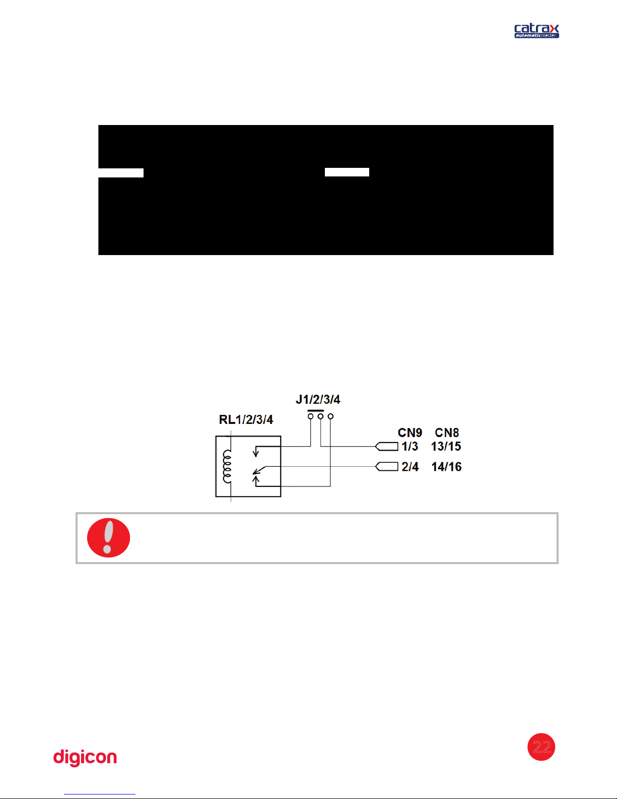
Enabling passage through tension pulse is shown in the image below. It is necessary to
observe the polarity of the C voltages and to use an external resistor for high voltagesD
(110V and 220V ).ac
6.5.1.1 Return signals
The control board has 4 return signals, two to indicate the moment, one to bob the
turnstile, and one to indicate the anti-panic system's status. All signals are originated
via relay – normally open contact (NO) or normally closed contact (NC). Connect the
outputs according to the image below:
6.5.1.2 Electromagnets
Electromagnets are activated for blocking the turnstile. Opposite to the traditional
solenoids, electromagnets do not cause abrasion between the coil and the locking
device, avoiding malfunctions. Moreover, the activation is done through a transistor,
and not a relay, avoiding the electromagnet to be blown due to the “contact wielding”
(there is no mechanical wear).
ATTENTION: The relay contacts have maximum capacity of 1A 125 V .ac
22
Vac ou Vdc
Vac ou Vdc
Page 23

Vca
6.5.1.3 Sound alarm
The
sound alarm output is activated by a NPN transistor (maximum 500 mA) every
time that Automatic :Master
-receives a clearance signal (two short rings)
-is not cleared and is forced during 1 second (1-second rings)
-is stuck mid-turn for over 2 seconds (1-second rings)
Connect the outputs according to the following image:
6.5.1.4 Connection scheme
23
Vac
Sound alarm
Maximum current: 500mA
INPUTS
INPUTS
OUTPUTS
RALAY
ACCESS CONTROL BOARD
OUTPUTS
DIGICON CONTROL BOARD
RETURN
SIGNALS
Page 24
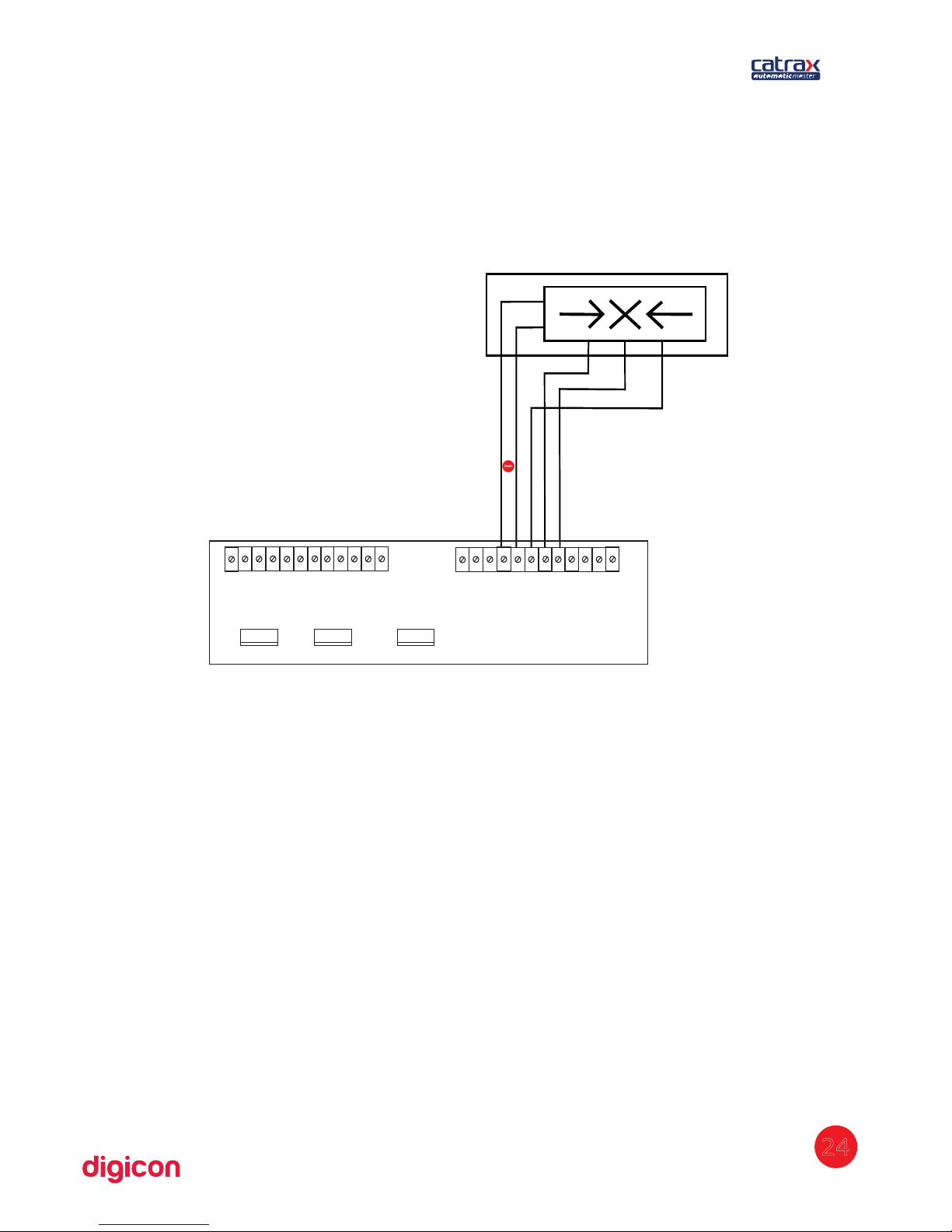
6.4.1.2 Pictogram
The pictogram's outputs are activated by NPN transistors (maximum 500 mA) at
the moment of activation, the GND is sent through a corresponding output.
6.7.2 Outputs
A
utomatic Master's board has outputs for return signals, electromagnets,
pictogram, collecting box, and sound alarm.
6.7.3 Configuration of control board
The switch (or dipswitch) DS1 allows programming the following actions:
-passage direction
-Maximum time for passage
-NO inputs (relay or pushbutton contact normally open and without input voltage),
enabling passage in face of these signals; or NC inputs (relay or pushbutton contact
usually closed and with input voltage), enabling passage in the absence of these
signals.
-enabling of a signal for a sound alarm if the access control remains at mid passage
for more than 2 seconds.
To program DS1, put each pin in the desired position, according to the table below:
24
GND
+ 24V / 12V
OUTPUT NPN 500mA
OUTPUT NPN 500mA
OUTPUTNPN 500mA
12 11
10
9
8
7
6
5
4
3
2
1
12 11
10
9
8
7
6
5
4
3
2
1
BOX SENSOR ELECTROMAGNETS TURNSTILE SENSORS
DIGICON CONTROL BOARD
INPUTS CN8
OUTPUTS CN9
Page 25
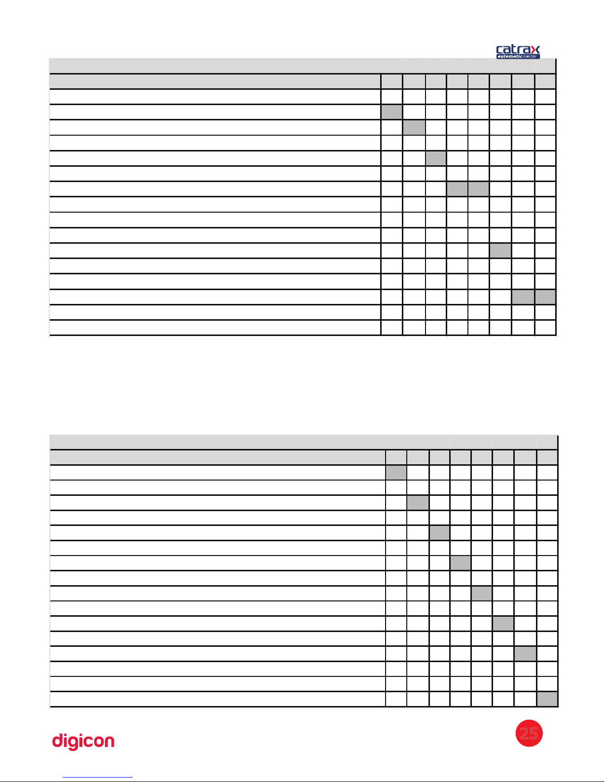
CHAVE 1 2 3 4 5 6 7 8
Enables sound signal ON
Disables sound signal OFF
NO inputs ON
NC inputs OFF
Habilitation per border OFF
Habilitation per level ON
Blocked in both directions ON ON
Blocked form right to left OFF ON
Blocked from left to right ON OFF
Cleared in both directions OFF OFF
Enables sound signal in mid-turn ON
Disables sound signal in mid-turn OFF
Wait until first turn (no turning timeout) ON ON
05 seconds turnstile 120° 05 seconds turnstile CLIP OFF ON
10 seconds turnstile 120° 15 seconds turnstile CLIP ON OFF
15 seconds turnstile 120° 20 seconds turnstile CLIP OFF OFF
DIP SWITCH DS1
The switch (or dipswitch) DS2 allows programming the following actions:
- invitation
- turning speed
- passage counting
To program DS2, put each pin in the desired position, according to the table below:
CHAVE 1 2 3 4 5 6 7 8
Enables invitation ON
Disables invitation OFF
Nominal speed ON
Half nominal speed OFF
Enables clockwise counting ON
Disables clockwise counting OFF
Enables counter clockwise counting ON
Disables counter clockwise counting OFF
Enables bob return and disables box ON
Enables box return and disables bob OFF
Retention time of the card in the box for reading 1s ON
Retention time of the card in the box for reading 2s OFF
Disk emulation for MCA ON
Disables disk emulation (Standard Control Board Operation) OFF
Firmware Type Turnstile 120° ON
Firmware Type Turnstile CLIP OFF
DIP SWITCH DS2
25
Page 26
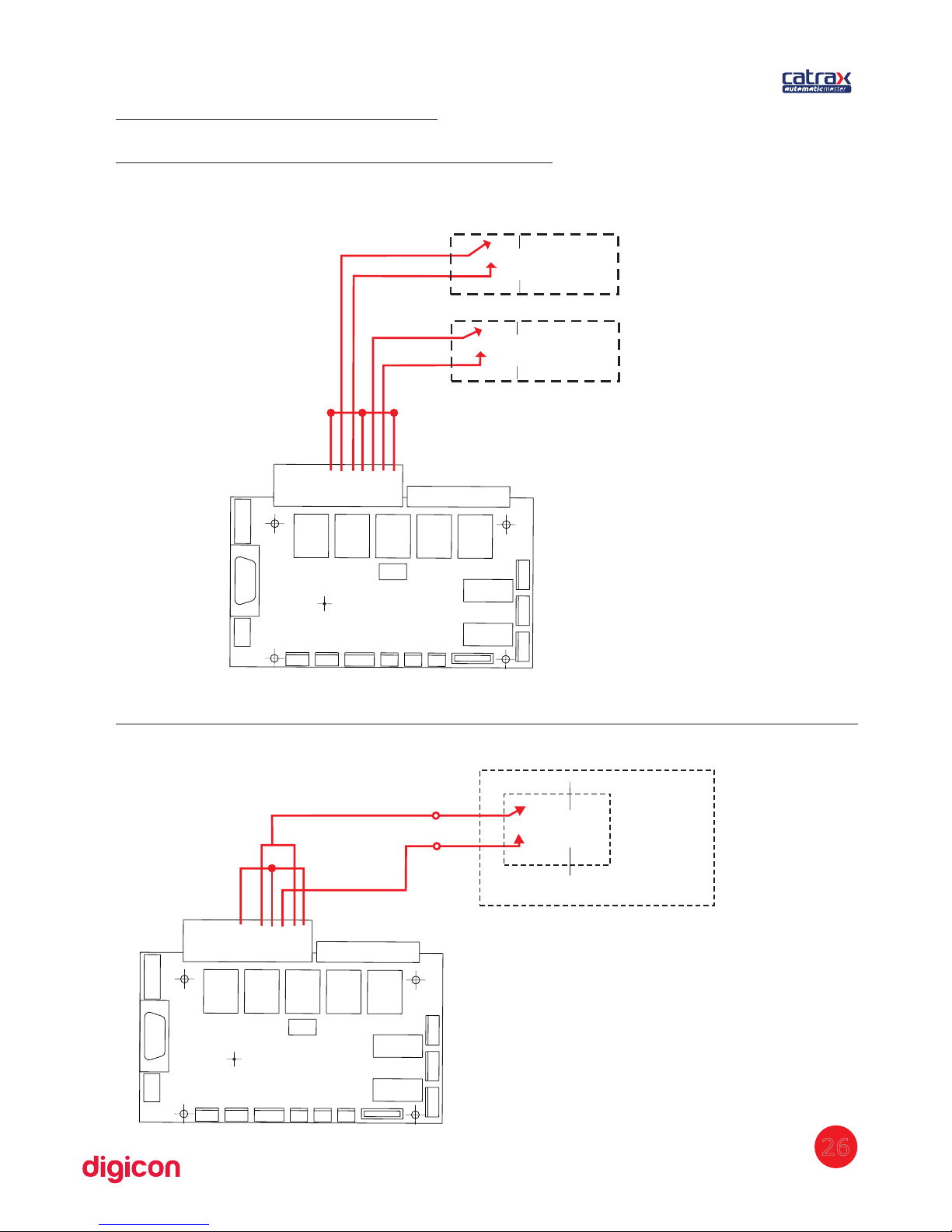
6.7.4 Turnstile Interface
Enabling through Dry contact with 2 relays:
Enabling both ways (Clockwise and Counter Clockwise) with 1 single relay:
7654321
U
U
U
U
U
U
U
U
U
U
Dry contact
Enabling
Clockwise
Enabling
Counter Clockwise
7654321
UUUUU
Relay
Integrator’s controller board
26
Dry contact (simultaneos)
Page 27
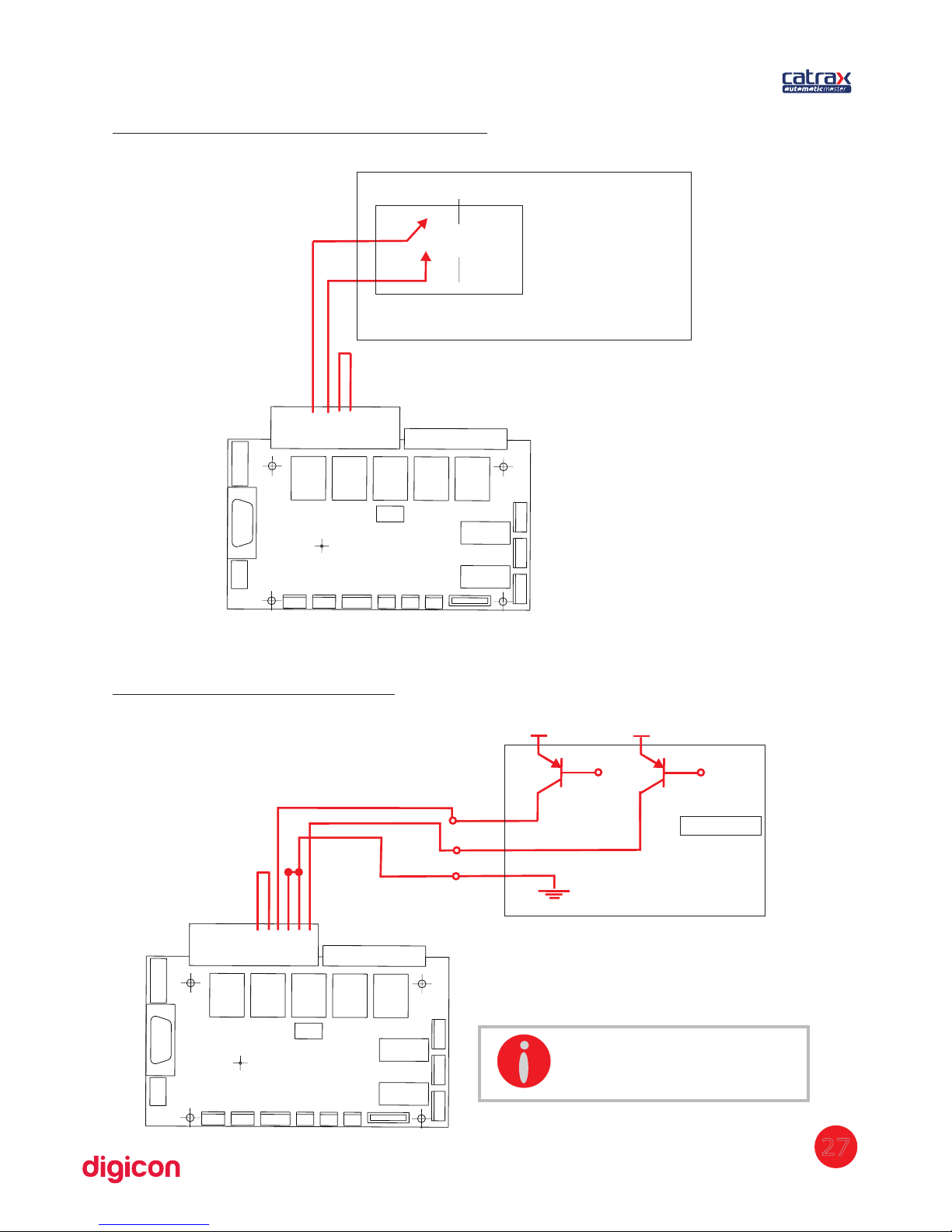
654321
CCW
CW
Vdc
Vdc
Vdc = 5~24V
Integrator’s controller board
Anti panic/drop arm mechanism input:
Enabling through solid state :
10987
UUUUU
Integrator’s controller
27
Dry contact
INFORMATION:
CCW: Counter Clockwise
CW: Clockwise
Page 28
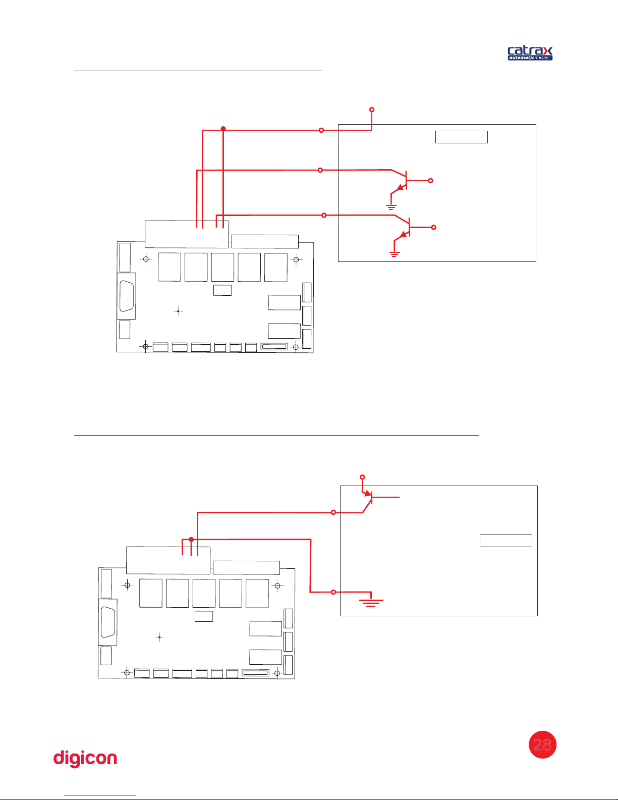
Enabling through solid state(negative):
Activating through solid state(anti panic/Drop arm mechanism):
1098
Vdc
Vdc = 5~24V
Anti panic
28
54321
Vdc
Vdc = 5~24V
CCW
CW
Integrator’s controller
Integrator’s controller
Page 29
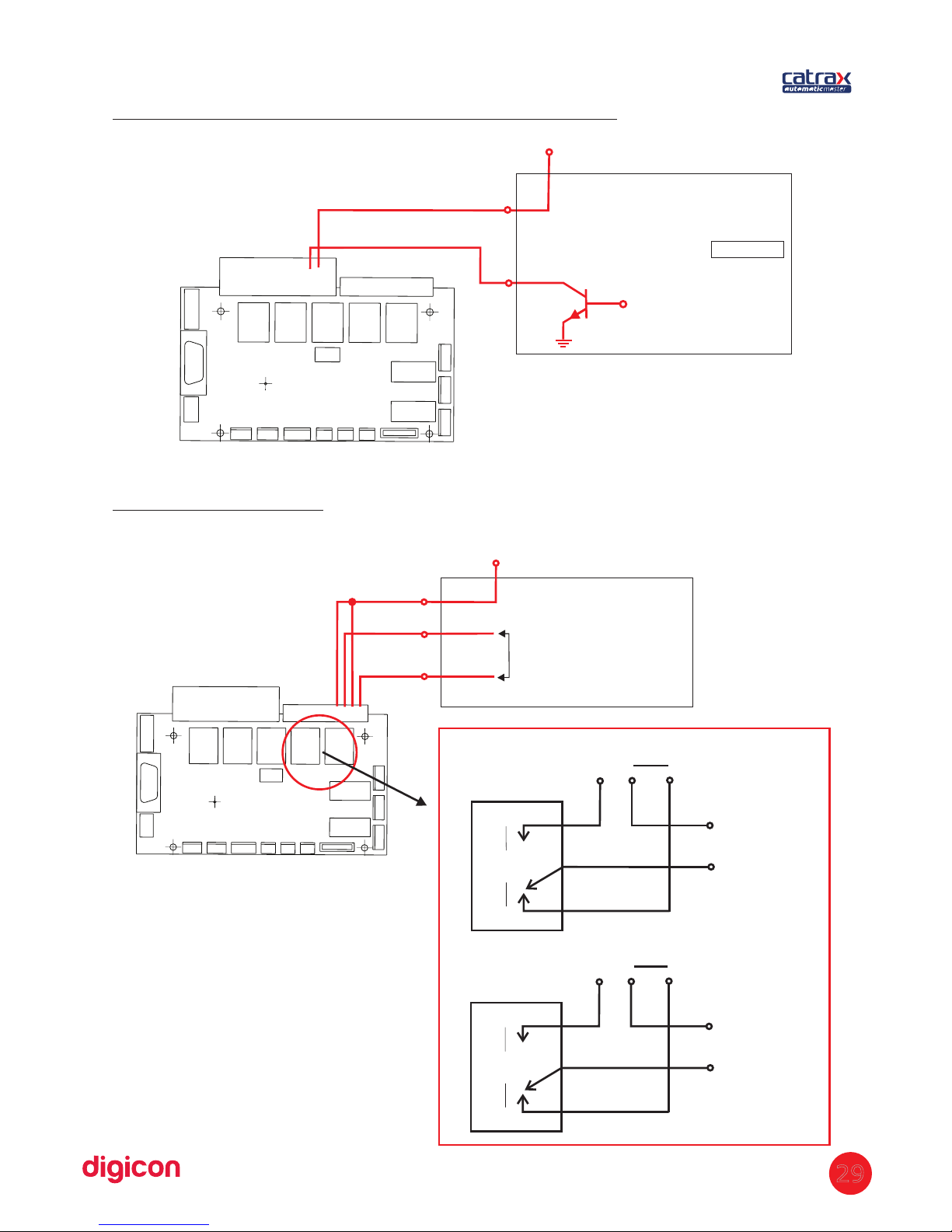
Activating through solid state (Drop arm/Negative).
Passage confirmation
Vcc - Rel logic lever, SH in ’’disk emulation’’ DIP Ds2 n°7 in mode ON.
Vdc
4321
Digital positive input
UUUUU
NA NF
Rl2
3
4
NO NC
1
2
Rl1
UUUUU
CW
CCW
29
98
Vdc = 5~24V
Vdc
Integrator’s controller
Integrator’s controller
Page 30
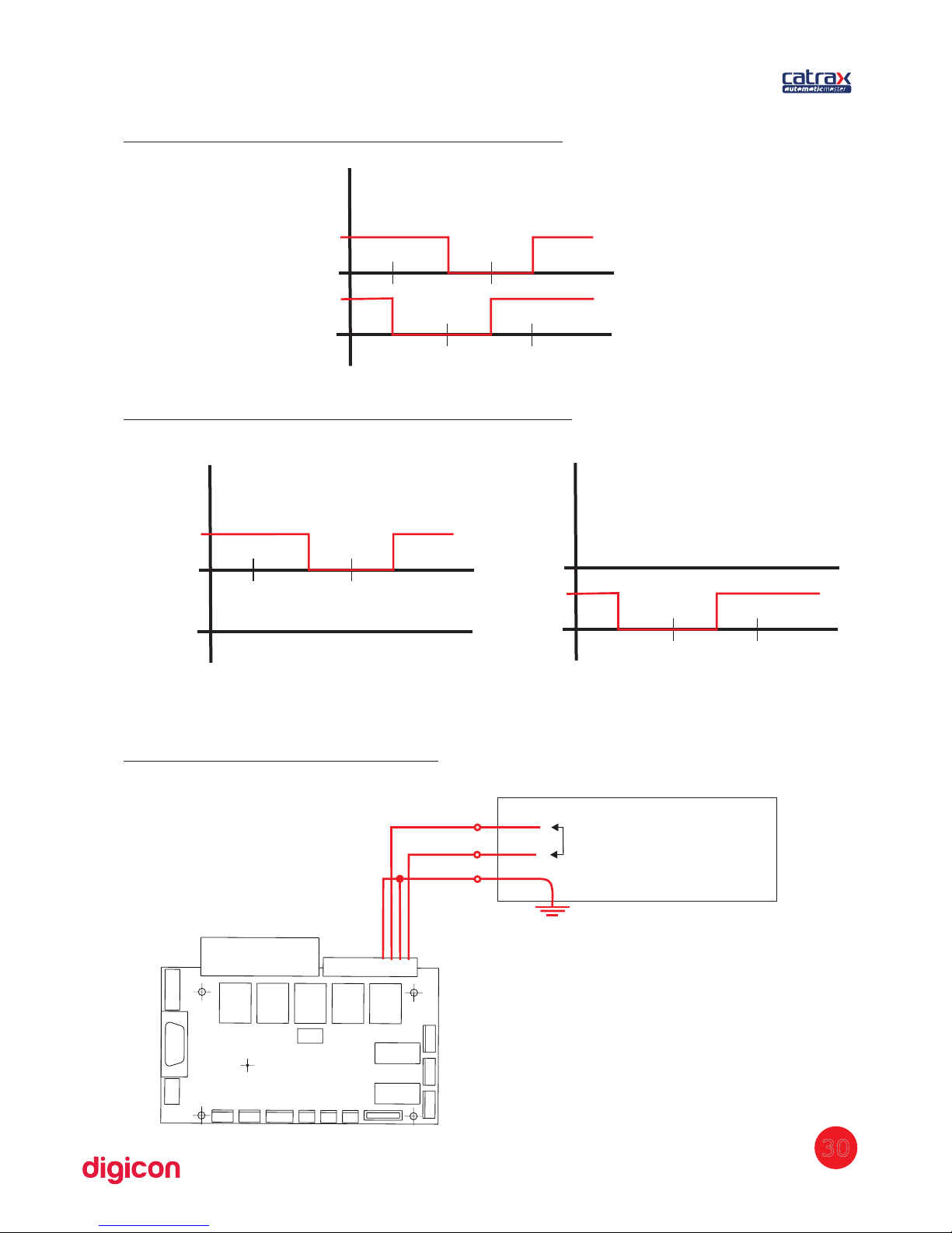
Passage confirmation through disk emulation
Passage confirmation through clockwise pulse
Passage confirmation through ’’disk emulation’’ can be set through dip switch Ds2,
nº7 in case it’s on it’ll emulate disk. On the other hand it’s off, it’ll general pulse.
Passage confirmation(negative)
30
1
1
1
1
Rl1
Rl1
Rl2
Rl2
4321
Digital negative input
Integrator’s controller
Page 31
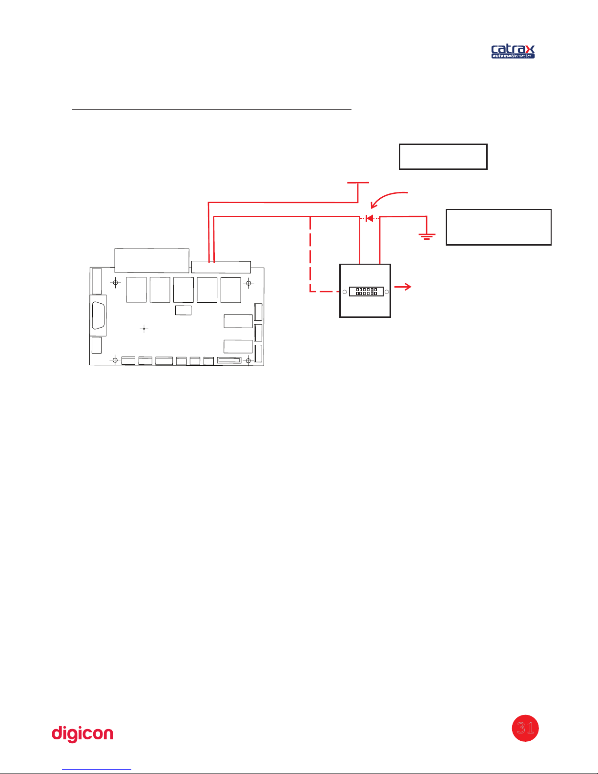
Electromechanical counter connections
87
Counter
Vdc
protection diode
In case you use inductive
counter it will be necessary
a protection diode
Inductive counter
Depends on the
couter tension
31
Page 32
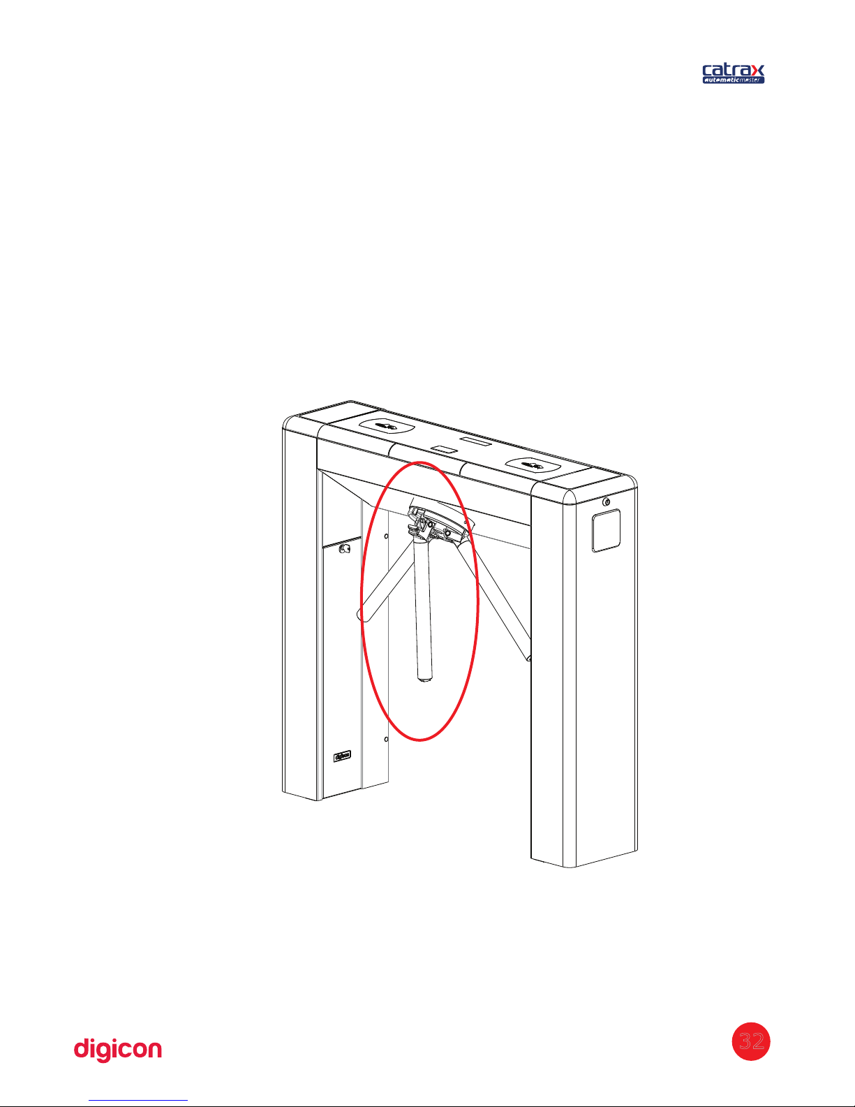
6.8 Anti-panic system
Automatic Master has an electromechanical device for anti-panic system (also
called drop-arm device). The mechanism is composed by a mechanical set
activated by high-performance solenoid, maintaining the arm raised during
normal operation. In case of power outage (when the installation has no nobreak), or through a command sent via system, or the activation of an emergency
button in the control room, the electromechanical device is deactivated, dropping
the arm that prevents turn, clearing the entrance of any barrier. This device can be
connected in series, allowing the clearance of all turnstiles at once from one single
point.
32
Page 33

6.8.1 Maintenance test
The anti-panic system (drop-arm) was developed to facilitate the exit of people in
emergencies. Thus, as a preventive measure, we recommend regular tests and
inspections in this device (at least once a month). If the mechanism presents any
defect, request maintenance to a Digicon technician or a qualified company.
Each inspection should carry out the following operational sequence for each of the
three arms:
- set the arm on the horizontal position;
· turn the turnstile off;
· check if the arm drops (if the arm does not drop, contact the dealer or Digicon);
· turn the turnstile on;
· raise the arm until it reaches its normal position (the arm must stay in horizontal
position without external support; if it does not, contact the dealer or Digicon);
· repeat the procedure three times for each arm.
33
Page 34

7. Maintenance
7.1Preventive and corrective routine maintenance:
Electromagnets – Periodicity: ever 700 0 cycles.00
This routine maintenance requires the use of a multimeter. To check for the need of
corrective actions, disconnect the CN3 from the access control board and check the
electromagnets' resistance. The value must be between 11 and 12.5 ohms between
pins 1 and 2 and 3 and 4 of the electromagnet's connector. After measuring,
connect CN3 to the board again.
Corrective actions:
1. if you spot an incorrect resistance, a short-circuit or open electromagnet, replace it.
2. if the electromagnet is not working, check the board or the voltage
3. if the electromagnet is moving, fasten the base screws.
Electromagnets adjustments (if necessary)
1. Force the lock against the sprocket and the equipment's arm until the lock is
completely inside the first teeth (until the arm is locked)
2. then, release the fixing screws and press the electromagnet against the lock's frame,
so that its area is completely against the electromagnet
3. refasten the screws
Set of locks – Periodicity: every 700 00 cycles.0
To check for the need of corrective actions, you must:
-check the lock's correct position
-check the wear of the lock's fitting in the sprocket
Corrective actions
1. if the lock's position is incorrect, check the retaining ring and the spring that tightens
the set
2. if the lock's fitting to the sprocket is incorrect, replace the lock or the sprocket
3. if lock's end is worn, replace the lock
Sprocket set – Periodicity: every 700 000 cycles.
To check for the need of corrective actions, you must:
-check the wear of the sprocket's teeth
-check the gap between the central axis, the sprocket, and the keyway.
Corrective actions
1. if you observe wear on the parts' teeth, replace the parts.
2. if you see a gap between the sprocket and the axis/keyway set, replace the sprocket
or the keyway (to replace the sprocket, use a pulley puller).
34
ATTENTION: Preventive and corrective maintenance must be performed
by a professional trained/qualified by Digicon S.A.
Page 35

35
7.2 Solving problems
Defect
Possible causes
Action
· It will not turn
on.
· The power supply’s input
cable is not connected
properly
· The circuit breaker is off.
· Check the cables
and the fuse.
· It does not
activate the
electromagnet
(turnstile cannot
be locked).
· The cable is broken or the
distance between the
electromagnet and the
locking device is
maladjusted.
· Adjust the
electromagnet or
forward the
equipment to the
Technical
Assistance.
· The arm does not
remain in the
correct position.
· There is wear, dirt, a
broken spring or lack of
lubrication in the sphere
base.
· Request a
replacement for
the faulty part or
forward the
equipment to the
Technical
Assistance.
· It does not lock
in the first
tooth.
· The distance between the
electromagnet and the
locking device is
maladjusted.
· Adjust the
electromagnet or
forward the
equipment to the
Technical
Assistance.
Page 36
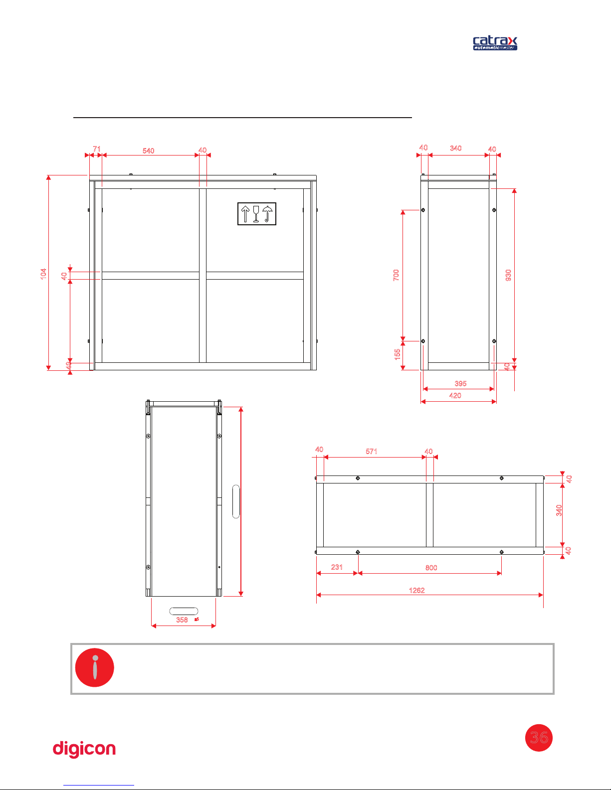
36
8. Technical characteristics
104
40
40
40
540
71
420
395
155
700
40
40
340
40
930
1262
231
800
40
40571
40
40
340
358
±5
1010
±5
INFORMATION: he arm/clip's size can be altered according to the client'sT
needs.
Page 37
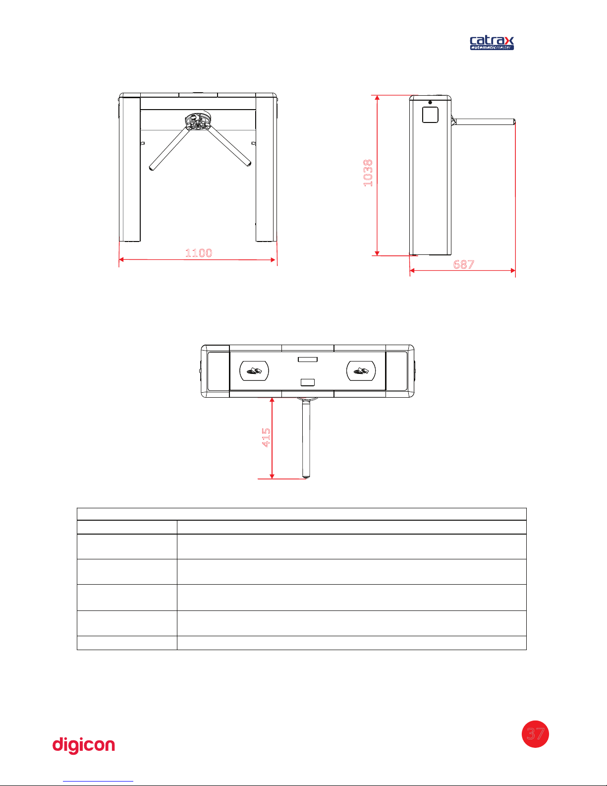
1100
687
1038
415
Outras informações
Gross weight: Approx. 100 kg (package included)
Distance
between arms
120 degrees
Electromagnets’
power
12Vcc / 2A
Power supply
Input: 100 Vac to 240 Vac 60HZ
Output: 24,0 Vdc +/- 5% 4,5 A
Operational
temperature
from 0ºC to 50ºC
Power Consumption during rotation is 36 W
37
Page 38

38
9. Warranty and technical assistance
Digicon is responsible for the project, skilled labor, and quality of the materials used in the
manufacturing of our products, ensuring that the equipment and all parts are free of
manufacturing defects or problems. Digicon commits itself to replace or repair, as we choose,
any part or equipment presenting manufacturing defects without any costs to the buyer, in our
factory in Gravataí or our branch office in São Paulo, in the conditions set below:
1. The buyer is responsible for the costs of shipping (return service) of the product to the factory
in Gravataí or the branch office in São Paulo.
2. The warranty period is counted from the date of emission of the bill of sale and encompasses:
a) 12 (twelve) months for equipment, accessories, parts, and pieces, including the legal
warranty period of 90 (ninety) days.
Legal warranty
The customer has the period of 90 (ninety) days, from the date of emission of the bill of sale, to
complain about apparent defects (easily observable in the product), such as the items that
constitute the product's exterior and any other area accessible to the user, just like appearance
parts and general accessories.
b) 90 (ninety) days for repairs or technical assistance
3. Warranty shall be granted to the buyer only in the face of the bill of sale (original or copy).
4. Warranty does not apply in the following cases or conditions:
a) defects and damages caused by accidents, negligence, or reasons of force majeure
b) defects and damages caused by inappropriate storage or lack of prolonged use
c) defects and damages caused by improper use of the equipment
d) defects and damages caused by improper operation or installation of the equipment
e) vandalism
f) natural impacts (lightning, flooding, etc.)
g)defects and damages caused by abnormal temperature conditions, voltage/frequency, or
humidity out of the levels specified in the installation and operation manual, once proven
h) reconditioning, chrome plating, nickel plating, and painting
5. Warranty shall be automatically canceled for equipment that:
a) suffers modifications, adaptations, or any alterations performed by the client or by third
parties without Digicon's written consent
b) goes through maintenance or repairs by people not authorized by Digicon
c) suffers alteration of serial number or violation of the identification label
d) is not paid for in the conditions, amounts, and deadlines described in the bill of sale
6. Digicon is not responsible for eventual losses suffered by the down time of the equipment
7. The repair of a warranted product will be performed inside the Digicon facilities.
Page 39

Page 40

Head office/RS
Factory, Technical Assistance, and Sales
Development, Technical Assistance, and Sales
Street Nissin C
astiel, 640 - Distrito Industrial.
Gravataí/RS CEP 94045-420
Phone:(0xx51) 3489.8700 / 3489.8745
Technical assistance:(0xx51) 3489.8903
Fax: (0xx51) 3489.1026
Email: [email protected]
Branch office/ SP
Street São Paulo, 82
Alphaville.
Barueri/SP CEP 06465-130
Phone: (0xx11) 3738.3500
Fax: (0xx11) 4191.2585
Email: [email protected]
Home page: www.digicon.com.br
 Loading...