


486-GL VESA Main Board Specifications:
Central Processing Unit:
Intel 486 SX-25/30; 486 DX-33/40/50; 486 DX250/66; Intel SL enhance serial CPU; Intel DX475/100; P24T; P24D; CX 486S/S2/DX/DX2
(M6,M7)
*(The manual does not mention AMD chips here,
but the board does support them and they are listed
under jumper settings)
Main Memory: On board MAX 128MB
On Board Memory Model:
2MB; 4MB; 8MB; 16MB; 20MB; 24MB; 28MB;
32MB; 34MB; 40MB; 48MB; 52MB; 64MB;
128MB
DRAM Access Cycle Time: 80ns
Cache Memory:
• Write-Back Direct-Mapped Cache
• 64K; 128K; 256K (Option)
• Supports 2-1-1-1,3-1-1-1, 2-2-2-2, and 3-2-
2-2 cache burst cycles
Data Bus Widths: 32 Bit
I/O Slots:
8 Expansion slots
• 8 bit x 2
• 16 bit x 6/VESA slot x 3
Dimension: 22cm x 25cm (2/3 Baby AT size)
PCB Layout: 4 Layers PCB
BIOS:
AMI WinBIOS
FLASH ROM BIOS optional
Chip Set: OPTi 895/602
CPU Type: PGA (With ZIF Socket) or PQFP
AT Clock:
AT-bus clock selectable from CPU CLK (/6, /5,
/4, /3)
Other Features:
• Shadow RAM support for System BIOS
• Turbo/slow speed selection
• CAS# before RAS# refresh reduces power
consumption
• Hidden refresh support to enhance system
performance
• Supports full SMI Interface

SETTING UP YOUR 486-GL
Intorduction
The 486-GL mainboard has a number of jumper switches which allow you to tailor the
board to your particular hardware setup. For ease of access, the settings of these jumper
switches should be made before the 486-GL has been installed in your case.
How to Set Jumper switch
A jumper switch consists of two or more pins and a plastic slider, called a jumper, Witch
fits over these pins. Witch a two pin jumper, when the jumper is in position over the two
pins, the switch is ON (this shorts the two pins together); when the jumper is removed
from the two pins, the switch is OFF. If you wish to set a two pin jumper as OFF, and
remove the jumper, you should push the jumper ONE pin in order to void losing it. A
two pin jumper is only ON when the jumper is over both pins. With a three pin jumper,
two settings are possible. When the jumper is over pins 1 and 2 one setting is achieved;
and when the jumper is over pins 2 and 3 another setting is achieved.
Pin "1"
A small figure "1" can be seen next to one pin of some jumper switches and connectors
on your 486-GL. This indicates pin 1 of the jumper switch or connector. The other pins
are not usually numbered but follow in sequential order. Where there might be confusion
as to the numbering, all pins are numbered.
When connecting the jumpers attached to your case components to the jumper
connectors, particular attention must be paid to the orientation of the jumper with
regardspin 1. Unfortunately there is no color standard for the leads attached to case
components so we cannot specify which color lead should be attached to pin 1. In
general, however, the lead to be connected to pin 1 is often colored red, or is of a
different color from the other leads attached to the jumper.
486-GL Jumper Switch Setting
The illustration on the next pages shows the position of the jumper switches and jumper
connectors on you 486-GL mainboard. Compare this illustration with your mainboard to
locate the position of the jumper switchs.
JUMPER SETTING:
J1: External Battery

J2: Keylock/Power LED:
•1-3 Power LED Connector
•4-5 Keylock Connector
S1: Rest
JP1: PQFP CPU select:
•Close PQFP CPU Disable
•Open PQFP CPU Enable
JP2: 5Volts/3.3Volts CPU select:
•1-2, 4-5 5Volts CPU
•2-3, 5-6 3.3Volts CPU
JP6,JP7: SX/DX CPU select:
•Close "DX" CPU
•Open "SX" CPU
JP16: Turbo Switch:
•Close Turbo
•Open Non-Turbo
JP17: Turbo LED
JP18: Speaker
JP21: Hardware Wake Up Switch
JP26: Discharge Battery:
•2-3 Battery Enable
•1-2 Discharge
JP30: Monitor Type:
•Close Color
•Open Mono
JP32: Monitor Power - Saving Control
JP45: Intel SMI CPU select:
•Close Intel SMI CPU
•Open Other CPU
JP3,JP5,JP8,JP9,JP12,JP22,JP23,JP50: CPU Type select:
CPU Type JP3 JP5 JP8 JP9 JP12 JP22 JP23 JP50
486SX Open Open 2-3 Open Open 1-2 Open Open
487SX 2-3 2-3 1-2 Open Open 1-2 Open Open
486DX/DX2/DX4 1-2 2-3 1-2 Open Open 1-2 Open Open
AMD DX2-66/80 1-2 2-3 1-2 Open Open 1-2 Open 2-3
AMD DX4-100 1-2 2-3 1-2 Open Open 1-2 Open 1-2
P24T 1-2 2-3 1-2 2-3 Open 2-3 Open Open
P24D Open Close Close 1-2
CX486S M6 Open Open 2-3 1-2 Open 1-2 Open 2-3
CX486DX M7 1-2 2-3 1-2 1-2 Open 1-2 Open 2-3
JP43,JP27: SMI CPU select:
CPU Type JP43 JP27
Intel SLe CPU Open Open
AMD SMI CPU Open Open
DX4 P24C 3X Open Open
DX4 P24C 2X 1-2 Open
CX486DX M7 1X Open 1-2
CX486DX M7 2X Open 2-3
Other CPU Open Open
JP48,JP40,JP39,JP38,JJ2: CPU CLK select:
Clock JP48 JP40 JP39 JP38 JJ2
20MHz 1-2 Open Close Open 1-2
25MHz 1-2 Open Close Close 1-2
33MHz(DX2-66,DX4-100 CPU) 1-2 Close Open Close 1-2
33MHz(DX4-100 CPU) 2-3 Open Open Close 1-2
40MHz(DX-40, DX2-80 CPU) 1-2 Close Close Open 1-2
50MHz 1-2 Close Close Close 1-2
50MHz(DX4-100 CPU) 2-3 Open Close Close 2-3
JP46: VL-Bus CLK speed select:
LCLK JP46
>33MHz 1-2
<=33MHz 2-3

JP10,JP11,JP13,JP35: Cache RAM Size select:
Cache Size JP10 JP11 JP13 JP35 U13 U5 - U8 U9 - U12
64KB Open Open 2-3 1-2 8KB*8 8KB*8 8KB*8
128KB Open Close 1-2 1-2 8KB*8 32KB*8 -------256KB Close Close 2-3 1-2
2-3
32KB*8
16KB*8
32KB*8 32KB*8
JUMPER SWITCHES LOCATION:
INSERT GIF HERE
J1: External Battery
Your 486-GL comes with a battery build-in. This battery powers the real-time clock and
ensures that the SETUP data stored in the CMOS RAM are not lost whenyour computer
is turned off. The on-board battery is quite sufficient for normal use, but you may wish
to installan external battery which may provide longer usage. If you wish to connect an
external battery, you should connect it to J1 as illustrated above, and this battery will
then provide the backup powerfor your 486GL. Note that one of the leads attched to the
battery will be colored (usually red), and this lead must be attached to the pin marked
"1".
J2: Keylock/Power LED
If the case into which you wishto install your 486-GL has a keylock and power-on LED,
there will be a five-lead jumper connected to the panel in which the keylock and poweron LED are situated. You should plug this jumper directly onto J2. Take care that the
jumper is correctly oriented with pin 1 of J2.
S1: Rest
Most cases are fitted with a reset button to allow you to reboot your machine in case it
should "hang" during operation due to a faulty hardware or software configuration.
Attach the jumper from the reset button to S1.
JP1: PQFP CPU select
Set these jumper as OFF (open) only if a 485 PQFP is installed. Set the jumper as ON
(close) for all other type CPU.

JP16: Turbo Switch
Connect the jumper connected to the turbo switch on your system case directly to this
jumper connector.
JP17: Turbo LED
If the case into which you wish to install your 486-GL has a turbo LED to indicate when
the computer is running in the turbo mode, connect the jumper attached to this
component to JP17. The Turbo LED will illuminate when you enter the turbo mode, and
remain illuminated until you switch back to normal mode.
JP18: Speaker
Most cases have a small speaker build-in. Attach the jumper connected to the speaker
over the pins on JP18, ensuring that the colored wire (often red) is over Pin 1. Though
the speaker jumper is a four pin jumper, there are usually only two leads attached to the
jumper.
JP26: Discharge Battery (Discharge CMOS RAM)
Installed on your 486-GL is a battery which ensures that the real-time clock keeps time
and that SETUP information stored in the CMOS non-volatile RAM is not lost when
you turnyour computer off. The normal setting for JP26 will be with the jumper over
pins 1 and 2, which enable the on board battery. This is the default setting. It is possible
to make an incorrect setting in the SETUP program stored in the CMOS, which will
cause your computer to "hang" as soon as you turn on your computer. If this occurs you
may find it impossible to run the SETUP program to correct the faulty setting. This is
when you may need to set the jumper of JP26 over pins 1 and 2, which will discharge
the battery,thus causing the information stored in the CMOS RAM, including the
incorrect setting to be erased. You should place the jumper over pins 1 and 2 for about
ten seconds to discharge the battery and than replace it over pins 2 and 3 before
rebooting your system.
JP30: Monitor Type Select
Jumper JP30 should be set as OFF (open) for a monochrome monitor and ON (close) for
a color or vga monitor.
JP48,JP40,JP39,JP38: CPU Clock Speed Select
These Jumpers are setting up for your CPU clock speed.

JP3,JP5,JP8,JP9,JP12,JP22,JP23,JP50: CPU Type Select
The setting of these jumper switches depends on whether a 486DX or 486SX CPU is
installed.
JP10,JP11,JP13,JP35: Cache Size Select
The settings of these four jumper switches must be made according to the cache size
installed. The table below details the correct setting.
CPU JUMPER SETTING CHICKING LIST:
CPU TYPE Volt JP3 JP5 JP8 JP9 JP12 JP22 JP23 JP27
Intel 486SX-25 PQFP 5 Open Open 2-3 Open Open 1-2 Open Open
Intel 486SX-33 PQFP 5 Open Open 2-3 Open Open 1-2 Open Open
Intel 486SX-25 PGA 5 Open Open 2-3 Open Open 1-2 Open Open
Intel 486SX-33 PGA 5 Open Open 2-3 Open Open 1-2 Open Open
Intel 486DX-25 PGA 5 1-2 2-3 1-2 Open Open 1-2 Open Open
Intel 486DX-33 PGA 5 1-2 2-3 1-2 Open Open 1-2 Open Open
Intel 486DX-50 PGA 5 1-2 2-3 1-2 Open Open 1-2 Open Open
Intel DX2-50 PGA 5 1-2 2-3 1-2 Open Open 1-2 Open Open
Intel DX2-66 PGA 5 1-2 2-3 1-2 Open Open 1-2 Open Open
Intel 486SX-25
SLe
PGA 5 Open Open 2-3 Open Open 1-2 Open Open
Intel 486SX-33
SLe
PGA 5 Open Open 2-3 Open Open 1-2 Open Open
Intel 486DX-25
SLe
PGA 5 1-2 2-3 1-2 Open Open 1-2 Open Open
Intel 486DX-33
SLe
PGA 5 1-2 2-3 1-2 Open Open 1-2 Open Open
Intel 486DX-40
SLe
PGA 5 1-2 2-3 1-2 Open Open 1-2 Open Open
Intel 486DX-50
SLe
PGA 5 1-2 2-3 1-2 Open Open 1-2 Open Open
Intel DX2-50 SLe PGA 5 1-2 2-3 1-2 Open Open 1-2 Open Open
Intel DX2-66 SLe PGA 5 1-2 2-3 1-2 Open Open 1-2 Open Open
Intel DX2-66
P24D
PGA 5 Open Close Close Open
Intel P24T
OverDrive
PGA 5 1-2 2-3 1-2 2-3 Open 2-3 Open Open
Intel DX4-75
P24C 3X
PGA 3.3 1-2 2-3 1-2 Open Open 1-2 Open Open
Intel DX4-100
P24C 3X
PGA 3.3 1-2 2-3 1-2 Open Open 1-2 Open Open

Intel DX4-100
P24C 2X
PGA 3.3 1-2 2-3 1-2 Open Open 1-2 Open Open
AMD 486DX-33 PGA 5 1-2 2-3 1-2 Open Open 1-2 Open Open
AMD 486DX-40 PGA 5 1-2 2-3 1-2 Open Open 1-2 Open Open
AMD DX2-50 PGA 5 1-2 2-3 1-2 Open Open 1-2 Open Open
AMD DX2-66 PGA 5 1-2 2-3 1-2 Open Open 1-2 Open Open
AMD DX2-66 PGA 3.3 1-2 2-3 1-2 Open Open 1-2 Open Open
AMD DX2-80 PGA 3.3 1-2 2-3 1-2 Open Open 1-2 Open Open
AMD DX4-100 PGA 3.3 1-2 2-3 1-2 Open Open 1-2 Open Open
Cyrix 486S-33 M6PGA 5 Open Open 2-3 1-2 Open 1-2 Open Open
Cyrix 486S2-66 M6PGA 5 Open Open 2-3 1-2 Open 1-2 Open Open
Cyrix 486DX-40 M7PGA 5 1-2 2-3 1-2 1-2 Open 1-2 Open 1-2
Cyrix 486DX-50 M7PGA 5 1-2 2-3 1-2 1-2 Open 1-2 Open 1-2
Cyrix 486DX2-66M7PGA 5 1-2 2-3 1-2 1-2 Open 1-2 Open 2-3
CPU JUMPER SETTING CHICKING LIST:
CPU TYPE Volt JP38 JP39 JP40 JP43 JP45 JP48 JP50 JJ2
Intel 486SX-25 PQFP 5 Close Close Open Open Open 1-2 Open 1-2
Intel 486SX-33 PQFP 5 Close Open Close Open Open 1-2 Open 1-2
Intel 486SX-25 PGA 5 Close Close Open Open Open 1-2 Open 1-2
Intel 486SX-33 PGA 5 Close Open Close Open Open 1-2 Open 1-2
Intel 486DX-25 PGA 5 Close Close Open Open Open 1-2 Open 1-2
Intel 486DX-33 PGA 5 Close Open Close Open Open 1-2 Open 1-2
Intel 486DX-50 PGA 5 Close Close Close Open Open 1-2 Open 1-2
Intel DX2-50 PGA 5 Close Close Open Open Open 1-2 Open 1-2
Intel DX2-66 PGA 5 Close Open Close Open Open 1-2 Open 1-2
Intel 486SX-25 SLe PGA 5 Close Close Open Open Close 1-2 Open 1-2
Intel 486SX-33 SLe PGA 5 Close Open Close Open Close 1-2 Open 1-2
Intel 486DX-25
SLe
PGA 5 Close Close Open Open Close 1-2 Open 1-2
Intel 486DX-33
SLe
PGA 5 Close Open Close Open Close 1-2 Open 1-2
Intel 486DX-40
SLe
PGA 5 Open Close Close Open Close 1-2 Open 1-2
Intel 486DX-50
SLe
PGA 5 Close Close Close Open Close 1-2 Open 1-2
Intel DX2-50 SLe PGA 5 Close Close Open Open Close 1-2 Open 1-2

Intel DX2-66 SLe PGA 5 Close Open Close Open Close 1-2 Open 1-2
Intel DX2-66 P24D PGA 5 Close Close Close Open Open 1-2 1-2 1-2
Intel P24T
OverDrive
PGA 5 Close Close Close Open Open 1-2 Open 1-2
Intel DX4-75 P24C 3XPGA 3.3 Close Close Open Open Open 2-3 Open 1-2
Intel DX4-100
P24C 3X
PGA 3.3 Close Close Open Open Open 2-3 Open 1-2
Intel DX4-100
P24C 2X
PGA 3.3 Close Close Open 1-2 Open 2-3 Open 2-3
AMD 486DX-33 PGA 5 Close Open Close Open Open 1-2 Open 1-2
AMD 486DX-40 PGA 5 Open Close Close Open Open 1-2 Open 1-2
AMD DX2-50 PGA 5 Close Close Open Open Open 1-2 Open 1-2
AMD DX2-66 PGA 5 Close Close Open Open Open 1-2 Open 1-2
AMD DX2-66 PGA 3.3 Close Open Close Open Open 1-2 2-3 1-2
AMD DX2-80 PGA 3.3 Open Close Close Open Open 1-2 2-3 1-2
AMD DX4-100 PGA 3.3 Close Open Close Open Open 1-2 1-2 1-2
Cyrix 486S-33 M6 PGA 5 Close Open Close Open Open 1-2 2-3 1-2
Cyrix 486S2-66 M6 PGA 5 Close Open Close Open Open 1-2 2-3 1-2
Cyrix 486DX-40 M7PGA 5 Open Close Close Open Open 1-2 2-3 1-2
Cyrix 486DX-50 M7PGA 5 Close Close Close Open Open 1-2 2-3 1-2
Cyrix 486DX2-66 M7PGA 5 Close Open Close Open Open 1-2 2-3 1-2

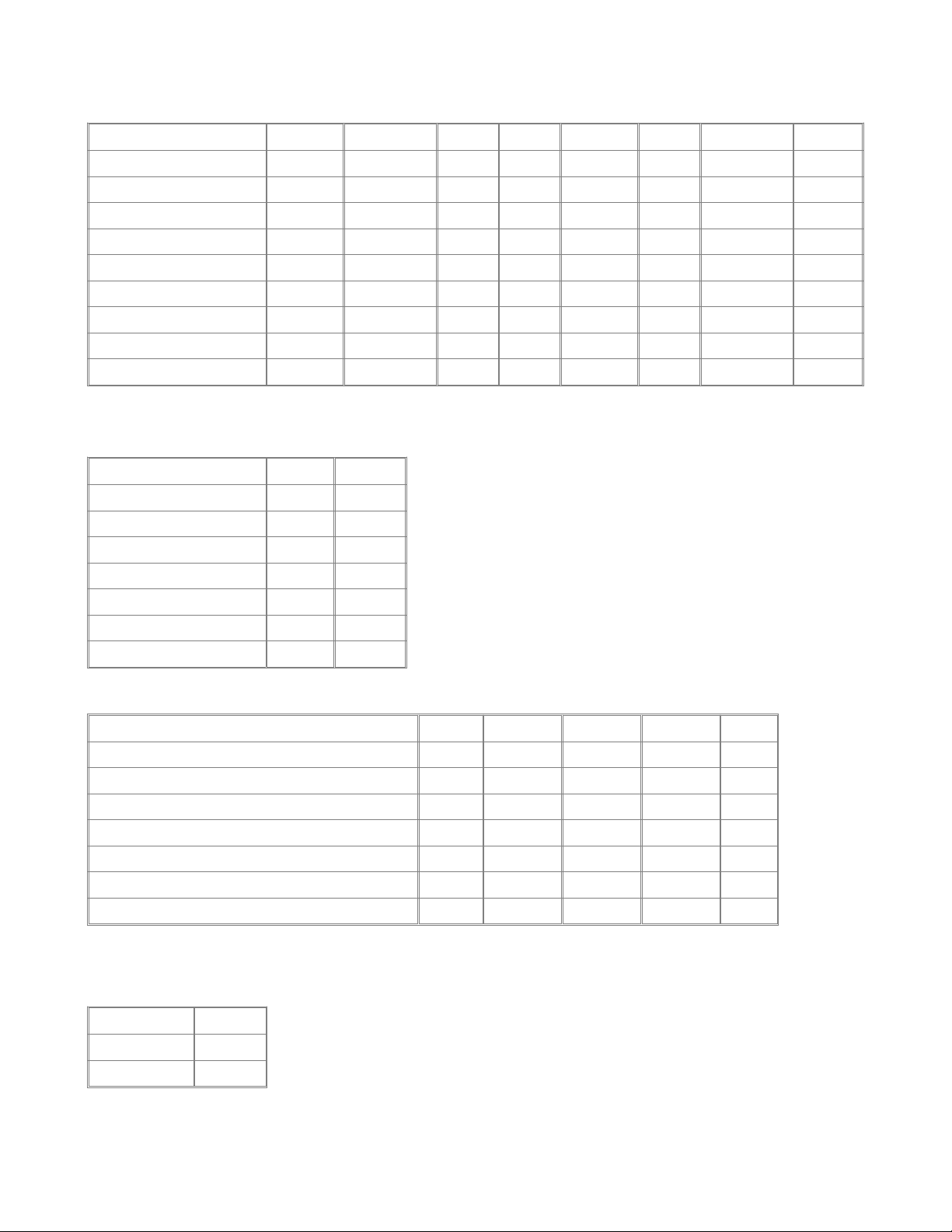
MEMORY CONFIGURATIONS:
The table below shows some possible combinations of SIMM's supported by the 486GL. The memory configuration shown in the table below.
Total Memory SIM4 SIM3 SIM2 SIM1
2M 0 0 1M 1M
2M 0 0 2M 0
4M 1M 1M 1M 1M
4M 2M 0 2M 0
4M 0 0 0 4M
5M 0 0 4M 1M
6M 0 4M 1M 1M
6M 0 4M 2M 0
8M 0 0 4M 4M
8M 0 0 8M 0
10M 4M 4M 1M 1M
10M 4M 4M 2M 0
10M 8M 0 1M 1M
10M 8M 0 2M 0
12M 4M 4M 0 4M
12M 8M 0 0 4M
16M 4M 4M 4M 4M
16M 8M 0 8M 0
16M 0 0 0 16M
17M 0 0 16M 1M
20M 0 0 16M 4M
32M 0 0 16M 16M
32M 0 0 32M 0
40M 0 8M 16M 16M
48M 0 16M 16M 16M
52M 4M 16M 16M 16M
64M 16M 16M 16M 16M
64M 32M 0 32M 0
64M 0 0 0 64M
128M 0 0 64M 64M
128M 0 0 128M 0
CACHE MEMORY CONFIGURATIONS:
The cache memory is configured as two banks; Bank 0 and Bank1. There is also one or
two TGA RAM chips, which is an integral part of the cache sub-system. Please refer to

the illustration of the board layout on jumper switch location, locate the two banks of
data cache SRAM and the TAG RAM chip. The table below illustrates the chip
configurations for each cache size.
Cache Size Bank 0 Bank 1 TAG RAM
64K 8Kx8 8Kx8 8Kx8 1pcs
128K 32Kx8 8Kx8 1pcs
256K 32Kx8 32Kx8 32Kx8 1 pcs or 16Kx8 1 pcs

The BIOS Features Setup
To access the BIOS Features Setup Program, highlight BIOS FEATURES SETUP in the
main menu and press <Enter>. A warning message will appear on your screen and you
may press any key to remove this and access the BIOS Features Setup program, as
illustrated below.
INSERT GIF HERE
External Cache These two categories speed up memory access.
Quick Power On Self Test This category speeds up Power On Self Test (POST) after
you power on the computer. If it is set to enable, BIOS will shorten or skip some check
item during POST.
Boot Sequence This category determines which drive computer searches first for the
disk operating system(i.e.,DOS). Default value is A,C.
Boot Up Floppy Seek During POST, BIOS will determine if the floppy disk drive
installed is 40 or 80 tracks. 360K type is 40 tracks while 760L, 1.2M and 1.44M are all
80 tracks.
Boot Up NumLock Status The default value is On.
•On: Keypad is number keys.
Off: Keypad is arrow keys.
Gate A20 Option
•Normal: keypad
•Fast: chipset
Security Option This category allows you to limit access to the system and Setup, or
just to Setup.
•System: This system will not boot and access too Setup will be denied if the
correct password is not entered at the prompt.
•Setup: The system will boot, but access to Setup will be denied if the correct
password is not entered at the prompt.
•Note: To disabled security, select PASSWORD SETTING at Main Menu and
then you will be asked to enter password. Do not type anything and just press
<Enter>, it will disable security. Once the security is disabled, the system will
boot and you can enter Setup freely.

Video BIOS Shadow It determines whether video BIOS will be copied to RAM, Video
Shadow will increase the video speed.
•Enable: Video shadow is enabled.
•Disabled: Video shadow is disabled.
C8000-CFFFF Shadow
D0000-DEFFFF Shadow
E0000-EFFFF Shadow
•These categories determine whether optional ROM will be copied to RAM by
16Kbyte.
The BIOS FEATURES SETUP allows you fine tune certain features supported by the
chipset and AWARD BIOS. It also includes support for shadow RAM under which the
contents of the ROM BIOS can be copied into memory at boot up, enhancing
performance. When you first access the BIOS FEATURES SETUP program the default
settings will be loaded. If you change any of the settings you may recall the default
setting at any time from the main menu.
The CHIPSET Features Setup
INSERT GIF HERE
The Power Management Setup
INSERT GIF HERE
PM Mode
•SMI Green: Pre-defined only for the Intel S-Serial CPU, That all of Power-
Management interrupt is using SMI.
•Auto Green: Pre-defined only for the other CPU (AMD, Cyrix...)
Power Management This category determines how power consumption for system after
selection below items. Default value is Disable.
•User Defined: All the power down time-out values are selected by user.

•Max power Saving: Auto setting power down time-out value to maximum power
consumption.
•Min power Saving: Auto setting power down time-out value to save minimum.
•Disable: Disable whole system power management function.
Doze timer Defines the continous idle time before the system entering DOZE mode
•Options: 15Sec 2Min 5Min 15Min 30Min 45Min 60Min 240Min
•Disabled: System will never enter DOZE mode.
•Note: This mode is only for Intel S-Serial, the CPU Clock will down to 8MHz in
DOZE mode.
Sleep timer Defines the continuous idle time before the system entering Sleep mode
•Options: 15Sec 2Min 5Min 15Min 30Min 45Min 60Min 240Min
•Disabled: System will never enter Sleep mode
HDD Standby Timer Select time-out value 1-15 minutes for IDE with disk auto standby.
This function depends on disk drive, some older mode disk drive don't support auto
standby function. system BIOS set this function before booting is HDD supported.
Disabled: HDD's motor will not off.
Sleep Clock This item is only for Intel S-Serial, the BIOS will automatically detect CPU
and disable this item if the CPU is not Intel S-Serial.
•Stop: To define the CPU stop in sleep mode
•Slow: To define the CPU slowdown (8MHz) in sleep mode
CRT Sleep
•Disabled: To define the CRT will not turn off during SLEEP mode
•Enable: To define the CRT will turn off during SLEEP mode
IRQ3-15 IRQ3-IRQ15 Monitor. These bits, if enabled, will allow the IRQ input to be
monitored for both inactivity for entering the Green Mode and activity for entering the
NORMAL Mode.
LDEV/LDEQ Detection These two bits, if enabled, will allow local bus devices to be
monitored for entering the GREEN Mode.

Video Detection This bit, if enabled, will allow video port devices to be monitored for
entering the GREEN Mode.
HDD Detection This bit, if enabled, will allow hard disk port devices to be monitored
for entering the GREEN Mode.
FDD Detection This bit, if enabled, will allow floppy disk port devices to be monitored
for entering the GREEN Mode.
DRQ0-7 Detection IRQ3-IRQ15 Monitor. These bits, if enabled, will allow the DRQ
input to be monitored for both inactivity for entering the GREEN Mode.
The Load BIOS/Setup Defaults Setting
The BIOS/Setup Defaults setting are best-case Values that should optimize system
performance.
Manual taken from: http://www.physics.mun.ca/~dbpynn/mboard/mboard.html
 Loading...