

3G Router AM11
User’s Guide
rev. 1.0 01/2011
Router 3G Ethernet
Router with built-in 3G HSUPA embedded module
Router with WAN Ethernet interface
WAN/3G automatic BackUP
Wireless LAN 11N up to 300Mps
3G embedded module


Restriction of use of Wireless Radio Equipment
using the
2.4GHz ISM frequency band
This equipment complies with european standards in matter of electromagnetic compatibility,
interference and safety. This equipment operates in the 2.4GHz Wireless radio bandwidth,
regulated by the European 1999/5/CE Directive. It can be freely used in those countries which
are not specifically applying restrictions.
Restrictions of use in France
• Indoor
The maximum transmit power (EIRP) is limited to 100mW (20 dBm) within the
2400-2483,5MHz frequency range
• Outdoor
The maximum transmit power (EIRP) is limited to 100mW (20 dBm) within the
2400-2454MHz frequency range
The maximum transmit power (EIRP) is limited to 10mW (10 dBm) within the
2454-2483,5MHz frequency range
Please check www.art-telecom.fr for updates and further informations.
Restrictions of use in France
This equipment can be used freely within private areas.
Should the equipment being used in public areas or outside private areas, the user must apply
a general authorization and inform the national telecommunication organization. Please refer
to www.comunicazioni.it for updates and further informations.
If the equipment allows to modify the transmit power level or change of the antenna type, the
user must ensure not to exeed the 100mW (20 dBm) limit in any case or final setup.
DECLARATION OF CONFORMITY
We, Digicom S.p.A., with registered office at Cardano al Campo (VA - Italy) - Via Volta 39,
declare under our sole responsibility, that the products named 3G Router AM11 to which this
declaration refers to, satisfy the essential requirements of following Directive:
- 1999/5/CE 9th March 1999, R&TTE (concerning radio equipment and telecommunication
terminal equipment and the acknowledgment of their conformity) Law Decree 9th May 2001,
n.269, (G.U. n. 156 of 7-7-2001).
As indicated in conformity with the requirements of following Reference Standards or of other
regulations documents:
EN 301 489-1
EN 301 489-17
EN 301 489-7
EN 301 489-24
EN 301 908-1
EN 50385
EN 301 511
EN 300 328
EN 60950-1
This device can be used in the following countries: IT, DE, ES, PT, BE, NL, GB, IE, DK, GR,
CH

!"#$%&
RESTRICTION OF USE OF WIRELESS RADIO EQUIPMENT USING THE 2.4GHZ ISM
FREQUENCY BAND ...................................................................................................................2!
DECLARATION OF CONFORMITY ...............................................................................2!
1.0! INTRODUCTION .................................................................................................................4!
1.1! PACKAGE LIST..................................................................................................................4!
1.2! HARDWARE INSTALLATION...........................................................................................5!
2.0! CONFIGURATION ............................................................................................................10!
2.1 Wizard .............................................................................................................10!
2.2 Advanced Setting .............................................................................................15!
2.2.1 Basic Setting .................................................................................................15!
2.2.2 Forwarding Rules..........................................................................................33!
2.2.3 Security Setting.............................................................................................36!
2.2.4 Advanced Settings.........................................................................................43!
2.2.6 SMS..............................................................................................................52!
2.2.7 Tool Box.......................................................................................................54!

1.0 Introduction
Congratulations on your purchase of this outstanding 3G Router 11 AM. The device is a
HSPA router with built-in HSUPA embedded module. It supports N AT, routing, firewall, VPN
pass-through, auto-3G-dial-up backup connection, DHCP server, and so on. And is easy to
configure and operate even for non-technical users. Instructions for installing and configuring
this product can be found in this manual. Before you install and use this product, please read
this manual carefully for fully exploiting the functions of this product.
1.1 Package List
items
Description
Quantity
1
WiFi Mobile Broadband
Gateway
1
2
Power adapter 12V 2A
1
3
CD
1
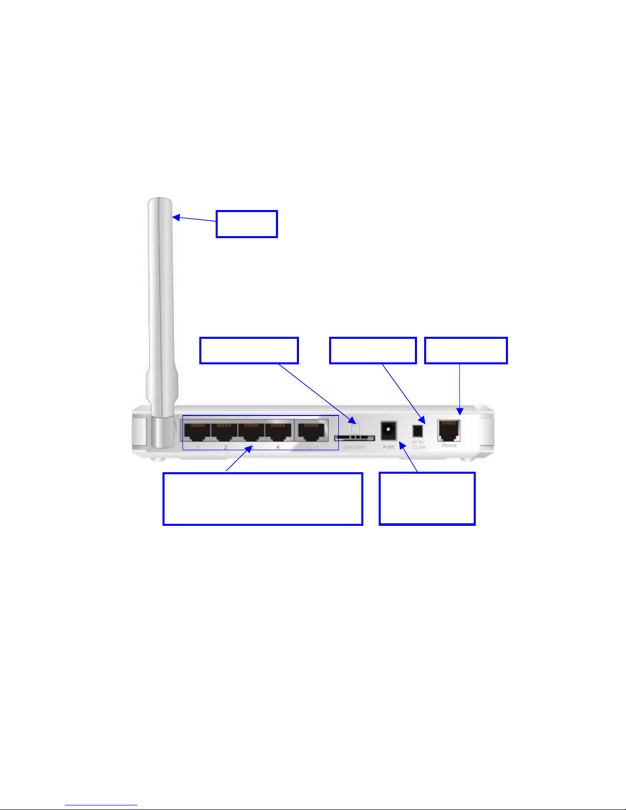
1.2 Hardware Installation
Hardware configuration
* Not Supported on 3G Router 11AM
USIM/SIM Slot
RJ-11 Port *
Power Switch
Antenna
Auto MDI/MDIX RJ-45 Ports
Automatically sense the types of WAN
and LAN when connecting to Ethernet
Receptor for
Power adapter
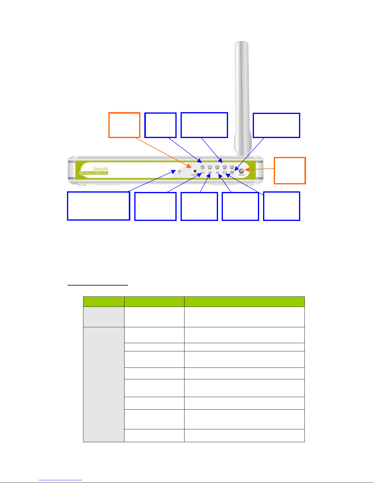
LED indicators
LED status
Description
Status
Green in flash
Device status is working.
Red in flash
Disconnected.
No SIM card / signal or unverified PIN code
Amber in flash
Connecting.
Red
Connected.
Signal strength in level one (weak)
Red in quick flash
Roaming alert, and 3G signal is weak
Amber
Connected.
Signal strength in level two or three (middle)
Amber in quick flash
Roaming alert, and 3G signal is middle
Green
Connected.
Signal strength in level four or five (strong)
3G Signal
Strength LED
Green in quick flash
Roaming alert, and 3G signal is strong
LAN1~LAN4
LEDs
WAN
LED
WLAN(WPS)
LED
Reset
Button
WPS
Button
SMS
LEDs
3G/3.5G
LED
2G/2.5G
LED
Status
LED
3G Signal Strength
LED

Green
EDGE or GPRS connection is established
2G/2.5G LED
Green in flash
Data packet transferred via 2G/2.5G
Green
UMTS/HSDPA/HSUPA connection is
established
3G/3.5G LED
Green in flash
Data packet transferred via 3G/3.5G
Green
SMS storage is full
SMS LED
Green in flash
There is any unread SMS in the storage
Green
RJ45 cable is plugged
WAN LED
Green in flash
Data access
Green
RJ45 cable is plugged
LAN LED
Green in flash
Data access
Green
WLAN is on
Green in flash
Data access
WiFi LED
Green in fast flash
Device is in WPS PBC mode
How to operate
Step 1. Attach the antenna.
1.1. Remove the antenna from its plastic
wrapper.
1.2. Screw the antenna in a clockwise
direction to the back panel of the unit.
1.3. Once secured, position the antenna
upward at its connecting joint. This will
ensure optimal reception.
1.4. And rip the “USIM/SIM & PWR” sign
label from “Pull” tag.
1.Turn off the Power Switch
first.
2.DO NOT connect WiFi HSPA
IAD to power before
performing the installation
steps below.
Step 2. Insert SIM/USIM to IAD.
NOTE:
2.1. The WiFi HSPA IAD builds in a
HSUPA 3G modem card. Please refer to
your service provider for detailed feature
information.
2.2. A 3G SIM/USIM Card with services is
MUST, the Data service and the Voice
service.
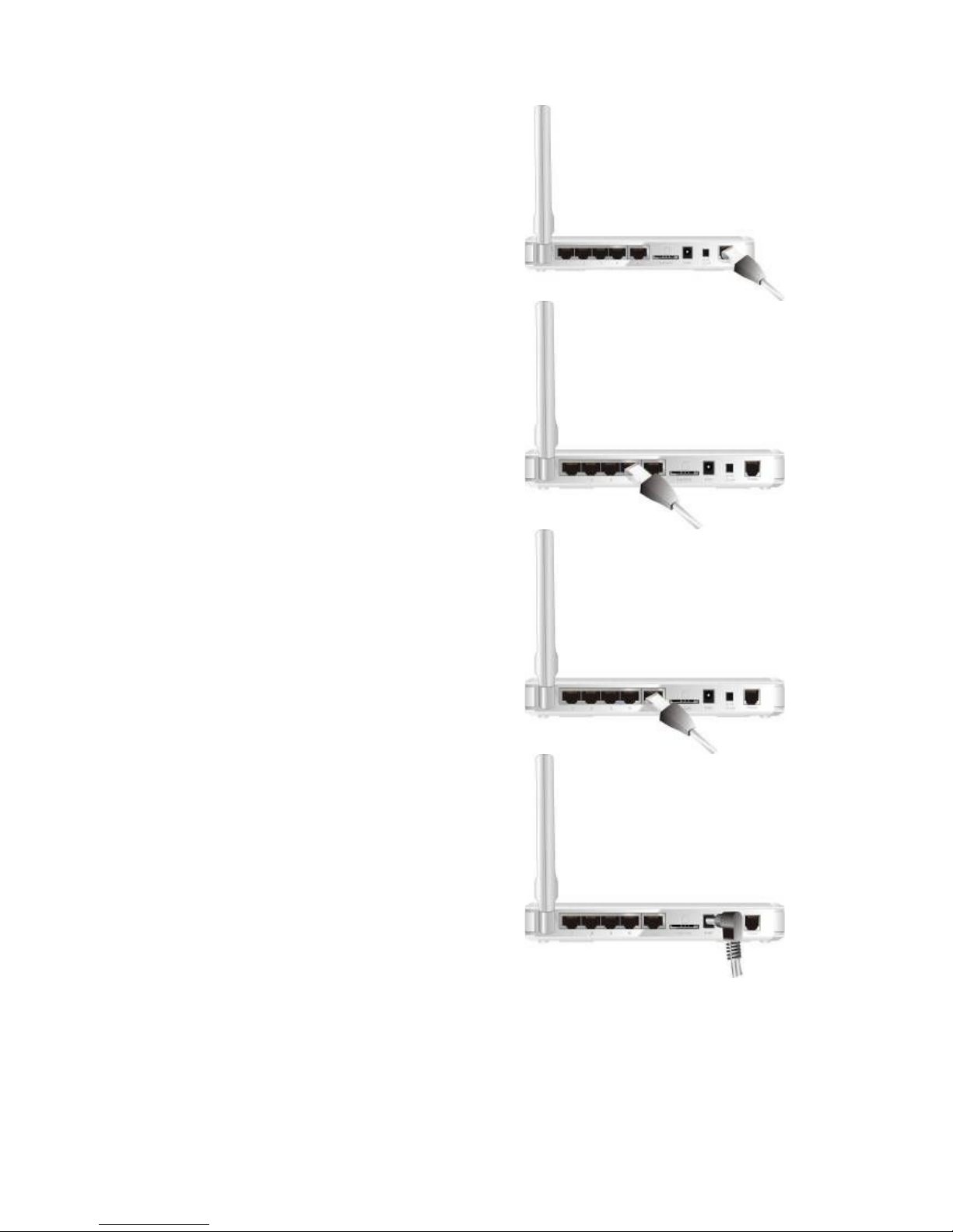
Step 3. Insert the RJ11 cable for a
Phone:
.You can make and receive 3G phone
calls by a RJ-11 Phone.
* RJ-11 Port is not supported on 3G Router
11AM.
Step 4 Insert the Ethernet cable into
LAN Port:
Insert the Ethernet patch cable into LAN
port on the back panel of the WiFi HSPA
IAD, and an available Ethernet port on the
network adapter in the computer you will
use to configure the unit.
Step 5 Insert the Ethernet patch cable
into Wired WAN port:
Insert the Ethernet patch cable into Wired
WAN port on the back panel of the WiFi
HSPA IAD.
NOTE: The step does not need if you
select the 3G Wireless WAN.
Step 6. Power on the IAD:
6.1. Connect the power adapter to the
receptor on the back panel of your WiFi
HSPA IAD.
6.2. Then plug the other end of the power
adapter into a wall outlet or power strip.
6.3. Turn on the Power Switch.

Step
7. Complete the setup.
7.1. All LEDs will transient illumination to
indicate power has been applied.
7.2. And then LEDs will flash ON and OFF
as the Wifi HSPA IAD performs
initialization and Internet connection
processes. This will take a few minutes.
7.3. When complete, the Status LED will
flash.

2.0 Configuration
2.1 Wizard
Type in the IP Address
(http://192.168.123.254)
Type password, the default is
“admin” and click ‘login’ button.
Select your language.
Press “Wizard” for basic
settings with simple way.

Press “Next” to start
wizard.
wizard
Step 1:
Set up your system password.
Step 2:
Select Time Zone.

Step 3:
Select Wan Type.
Auto Detecting or
Setup Manually.
Setup the LAN IP and WAN
Type.
Step 4:
Please fill in 3G service
information which is provided by
your ISP.
Example:

Step 5:
Set up your Wireless.
Set up your Authentication and
Encryption.
Step 6:
Then click Apply Setting.
And then the device will reboot.

Step
7:
Click Finish to complete it.
2
.2 Advanced Setting
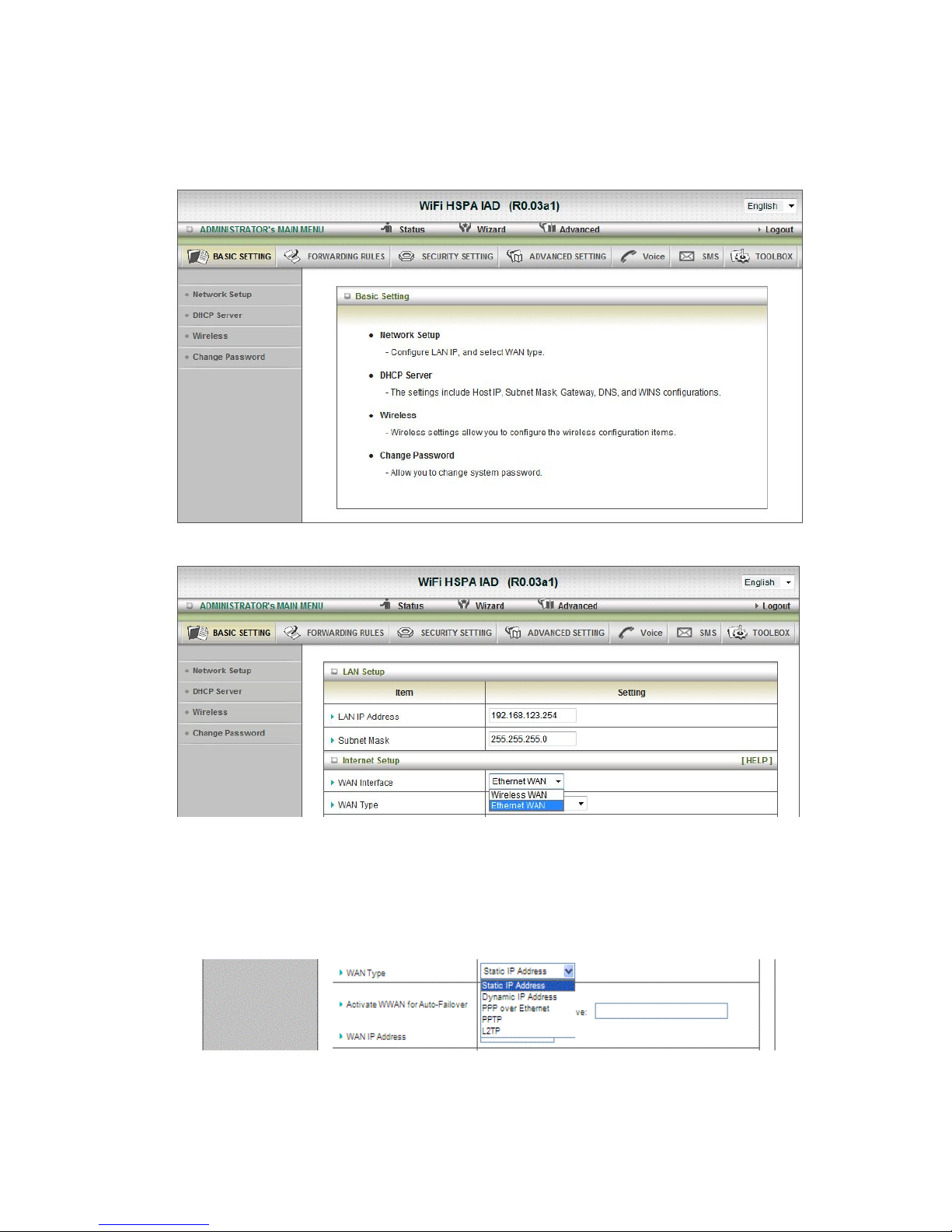
2.2.1 Basic Setting
1. Network Setup
1. LAP IP Address: the local IP address of this device. The computers on your
network must use the LAN IP address of your product as their Default Gateway. You
can change it if necessar y.
2. Subnet Mask: insert 255.255.255.0
3. WAN Interface: Select Ethernet WAN or Wireless WAN to continue.
4. WAN Type: WAN connection type of your ISP. You can click WAN Type Combo
button to choose a correct one from the following options:
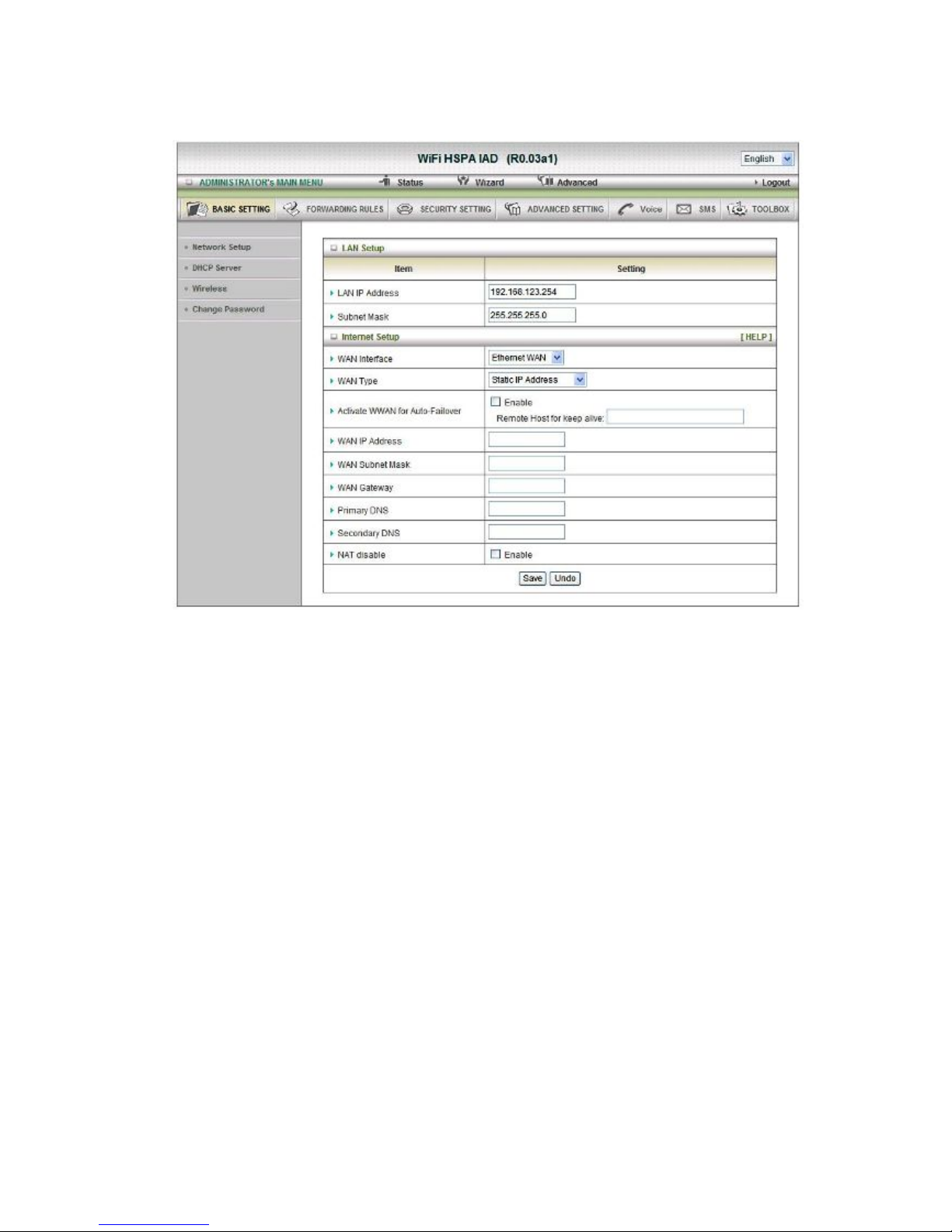
A. Static IP Address:
WAN IP Address, Subnet Mask, Gateway, Primary and Secondary DNS: enter the proper
setting provided by your ISP.

B.
Dynamic IP Address:
1. Active WWAN for Auto-Failover: The WAN type will be change to wireless-WAN
automatically, if the wired-WAN is defunct.
2. Host Name: optional, required by some ISPs, for example, @Home.
3. ISP register MAC address: You can change the WAN port MAC address, it is your ISP
assigned to you.
4. Connection Control: There are 3 modes to select:
Connect-on-demand: The device will link up with ISP when the clients send
outgoing packets.
Auto Reconnect (Always-on): The device will link with ISP until the
connection is established.
Manually: The device will not make the link until someone clicks the
connect-button in the Status-page.
5. NAT disable: the option bridges data form WAN port to LAN port.
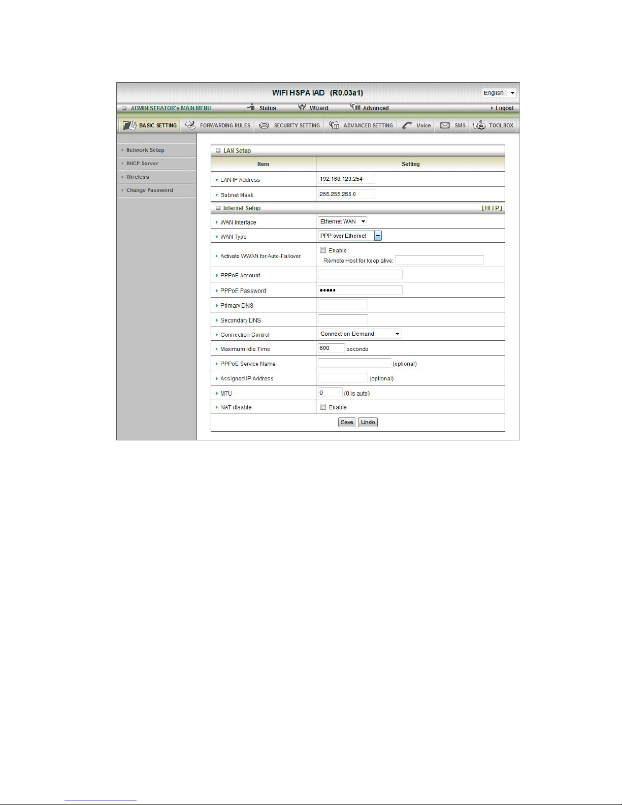
C.
PPP over Ethernet
1. Active WWAN for Auto-Failover: The WAN type will be change to wireless-WAN
automatically, if the wired-WAN is defunct.
2. PPPoE Account and Password: the account and password your ISP assigned to you.
For security, this field appears blank. If you don't want to change the password, leave
it empty.
3. Primary DNS/ Secondary DNS: This feature allows you to assign a
Primary/Secondary DNS Server, contact to your ISP to get it.
4. Connection Control: There are 3 modes to select:
Connect-on-demand: The device will link up with ISP when the clients send
outgoing packets.
Auto Reconnect (Always-on): The device will link with ISP until the connection is
established.
Manually: The device will not make the link until someone clicks the
connect-button in the Status-page.
5. Maximum Idle Time: the amount of time of inactivity before disconnecting your PPPoE
session. Set it to zero or enable !Auto-reconnect" to disable this feature.
6. PPPoE Service Name: optional. Input the service name if your ISP requires it.
Otherwise, leave it
blank.
7. Assigned IP address: Optional, Input the IP address you want. Usually, leave it blank.
8. Maximum Transmission Unit (MTU): Most ISP offers MTU value to users. The default
MTU value is 0(auto).
9. NAT disable: the option bridges data form WAN port to LAN port
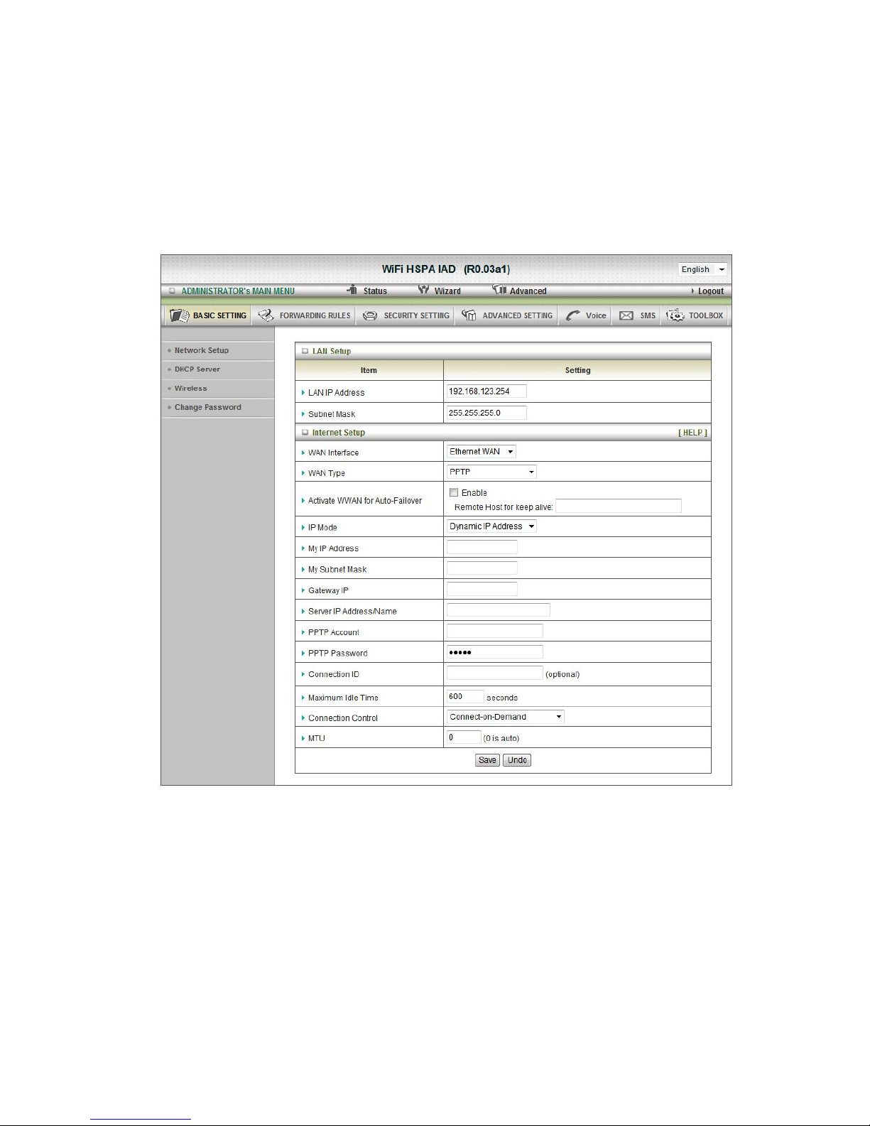
D. PPTP
First, please check your ISP assigned and select the IP Mode - Static IP Address or
Dynamic IP Address. For example: Use Static, the private IP address, subnet mask and
Gateway are your ISP assigned to you.
1. Active WWAN for Auto-Failover: The WAN type will be change to wireless-WAN
automatically, if the wired-WAN is defunct.
2. My IP Address, My Subnet Mask and WAN Gateway IP: the private IP address,
subnet mask and Gateway IP your ISP assigned to you.
3. Server IP Address/Name: the IP address or URL of the PPTP server.
4. PPTP Account and Password: the account and password your ISP assigned to you. If
you don't want to change the password, keep it empty.
5. Connection ID: optional. Input the connection ID if your ISP requires it.

6.
Maximum Idle Time: the time of no activity to disconnect your PPTP session. Set it to
zero or enable “Auto-reconnect” to disable this feature. If Auto-reconnect is enabled,
this product will connect with ISP automatically, after system is restarted or connection
is dropped.
Connection Control: There are 3 modes to select:
Connect-on-demand: The device will link up with ISP when the clients send outgoing
packets.
Auto Reconnect (Always-on): The device will link with ISP until the connection is
established.
Manually: The device will not make the link until someone clicks the #
connect-button in the Status-page.
7. Maximum Transmission Unit (MTU): Most ISP offers MTU value to users. The default
MTU value is 0(auto).

E. L2TP
First, please check your ISP assigned and select the IP Mode - Static IP Address or
Dynamic IP Address. For example: Use Static, the private IP address, subnet mask and
Gateway are your ISP assigned to you.
1. Activate WWAN for Auto-Failover: The WAN type will be change to
wireless-WAN automatically, if the wired-WAN is defunct.
2. IP Address, Subnet Mask and WAN Gateway IP: the private IP address, subnet
mask and Gateway IP your ISP assigned to you.
3. Server IP Address/Name: the IP address or URL of the PPTP server.
4. L2TP Account and Password: the account and password your ISP assigned to you.
If you don't want to change the password, keep it empty.
5. Maximum Idle Time: the time of no activity to disconnect your L2TP session. Set it
to zero or enable “Auto-reconnect” to disable this feature. If Auto-reconnect is
enabled, this product will connect with ISP automatically, after system is restarted
or connection is dropped.
6. Connection Control: There are 3 modes to select:
Connect-on-demand: The device will link up with ISP when the clients send
outgoing packets.

Auto Reconnect (Always
-on): The device will link with ISP until the connection is
established.
Manually: The device will not make the link until someone clicks the connect-button
in the Status-page.
7. Maximum Transmission Unit (MTU): Most ISP offers MTU value to users. The
default#MTU value is 0(auto).
Or select Wireless WAN for 3G Setting.
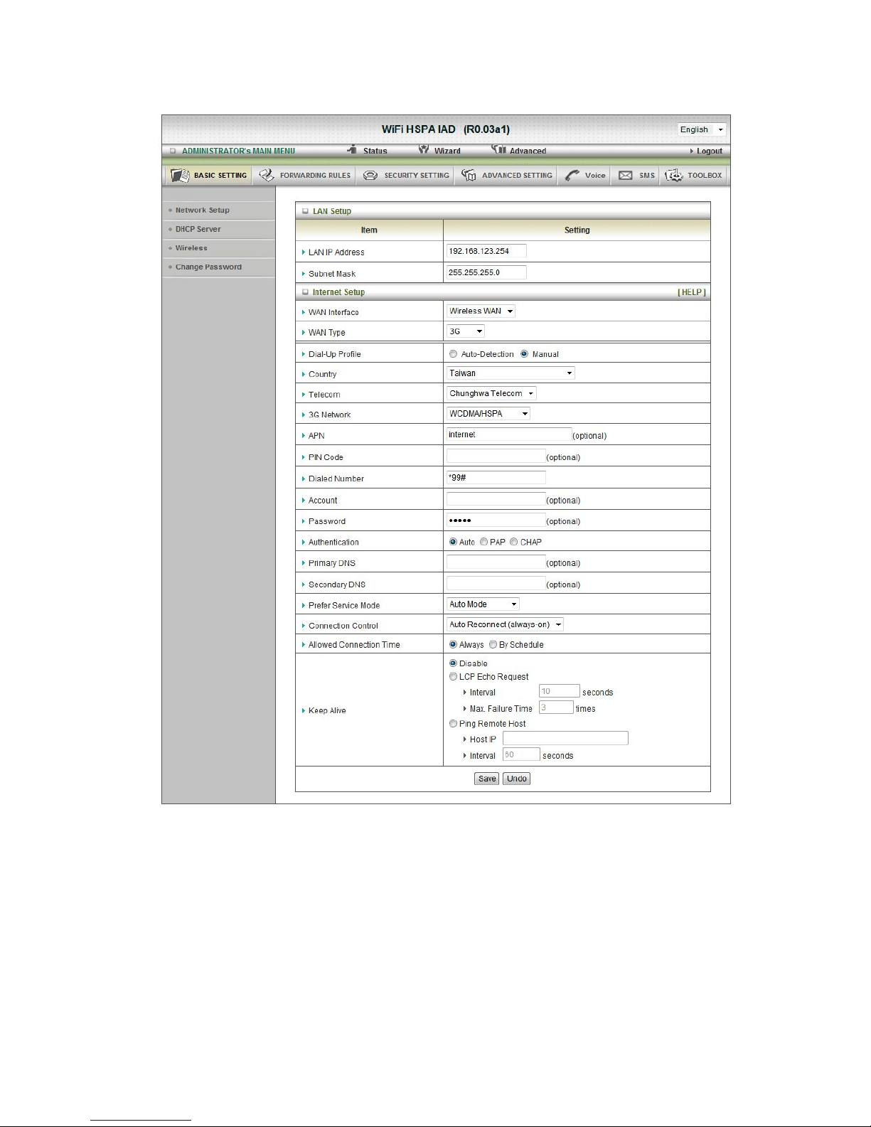
F. 3G
For 3G WAN Networking. The WAN fields may not be necessary for your connection. The
information on this page will only be used when your service provider requires you to enter a
User Name and Password to connect with the 3G network.
Please refer to your documentation or service provider for additional information.
1. Dial-Up Profile: select auto or manual to continue.
2. Country: select your country.
3. Telecom: select your telecom.
4. 3G Network: select the 3G Network.

5.
APN: Enter the APN for your PC card here.(Optional)
6. Pin Code: Enter the Pin Code for your SIM card(Optional)
7. Dial-Number: This field should not be altered except when required by your service
provider.
8. Account: Enter the new User Name for your PC card here, you can contact to your ISP
to get it.
9. Password: Enter the new Password for your PC card here, you can contact to your
ISP to get it.
10. Authentication: Choose your authentication.
11. Primary DNS: This feature allows you to assign a Primary DNS Server, contact to your
ISP to get it.
12. Secondary DNS: This feature allows you to assign a Secondary DNS Server, you can
contact to your ISP to get it.
13. Connection Control: select your connection control
14. Keep Alive: you can diagnose your connection by it.

2. DHCP Server
Press “More>>”,
1. DHCP Server: Choose either Disable or Enable
2. Lease Time: DHCP lease time to the DHCP client
3. IP Pool Starting/Ending Address: Whenever there is a request, the DHCP server
will automatically allocate an unused IP address from the IP address pool to the
requesting computer. You must specify the starting / ending address of the IP address
pool
4. Domain Name: Optional, this information will be passed to the client
5. Primary DNS/Secondary DNS: Optional, This feature allows you to assign a DNS
Servers
6. Primary WINS/Secondary WINS: Optional, this feature allows you to assign a WINS
Servers
7. Gateway: Optional, Gateway Address would be the IP address of an alternate
Gateway.
This function enables you to assign another gateway to your PC, when DHCP server
offers an IP to your PC.
Click on “Save” to store your setting or click “Undo” to give up

DHCP Clients List
The list of DHCP clients shows here.

DHCP Fixed Mapping
The DHCP Server will reserve the special IP for special MAC address, shows below.

3.
Wireless Settings
Wireless settings allow you to set the wireless configuration items.
1. Wireless Module: The user can enable or disable wireless function
2. Network ID(SSID): Network ID is used for identifying the Wireless LAN (WLAN).
Client stations can roam freely over this product and other Access Points that have the
same Network ID. (The factory setting is “default”)
3. SSID Broadcast: The router will broadcast beacons that have some information,
including ssid so that wireless clients can know how many AP devices by scanning
function in the network. Therefore, this function is disabled; the wireless clients can
not find the device from beacons.
4. Channel: The radio channel number. The permissible channels depend on the
Regulatory Domain.
The factory setting is channel 11.
5. Wireless Mode: Choose B/G Mixed, B only, G only, N only, G/N Mixed or B/G/N
mixed. The factory default setting is B/G/N mixed.
6. Authentication mode: You may select from nine kinds of authentication to secure
your wireless network: Open, Shared, Auto, WPA-PSK, W PA, WPA2-PSK, WPA2,
WPA-PSK/WPA2-PSK, WPA /WPA2.
Open
Open system authentication simply consists of two communications. The first is an
authentication request by the client that contains the station ID (typically the MAC
address). This is followed by an authentication response from the AP/router containing
a success or failure message. An example of when a failure may occur is if the client's
MAC address is explicitly excluded in the AP/router configuration.

Shared
Shared key authentication relies on the fact that both stations taking part in the
authentication process have the same "shared" key or passphrase. The shared key is
manually set on both the client station and the AP/router. Three types of shared key
authentication are available today for home or small office WLAN environments.
Auto
The AP will Select the Open or Shared by the client’s request automatically.
WPA-PSK
Select Encryption and Pre-share Key Mode
If you select HEX, you have to fill in 64 hexadecimal (0, 1, 2…8, 9, A, B…F) digits.
If you select ASCII, the length of pre-share key is from 8 to 63.
Fill in the key, Ex 12345678
WPA
Check Box was used to switch the function of the WPA. When the WPA function is
enabled, the Wireless user must authenticate to this router first to use the Network
service. RADIUS Server IP address or the 802.1X server’s domain-name.
Select Encryption and RADIUS Shared Key
If you select HEX, you have to fill in 64 hexadecimal (0, 1, 2…8, 9, A, B…F) digits
If you select ASCII, the length of pre-share key is from 8 to 63.
Key value shared by the RADIUS server and this router. This key value is consistent
with the key value in the RADIUS server.
WPA-PSK2
WPA-PSK2 user AES and TKIP for Same the encryption, the others are same the
WPA-PSK.
WPA2
WPA2 add uses AES and TKIP for encryption, the others are same the WPA.
WPA-PSK/WPA-PSK2
Another encryption options for WPA-PSK-TKIP and WPA-PSK2-AES, the others are
same the WPA-PSK.
WPA/WPA2
Another encryption options for WPA-TKIP and WPA2-AES, the others are same the
WPA.

WDS(Wireless Distribution System) Setting
WDS operation as defined by the IEEE802.11 standard has been made available. Using WDS
it is possible to wirelessly connect Access Points, and in doing so extend a wired infrastructure
to locations where cabling is not possible or inefficient to implement.
WPS (Wi-Fi Protection Setup)
WPS is Wi-Fi Protection Setup which is similar to WCN-NET and offers safe and easy way in
Wireless Connection.
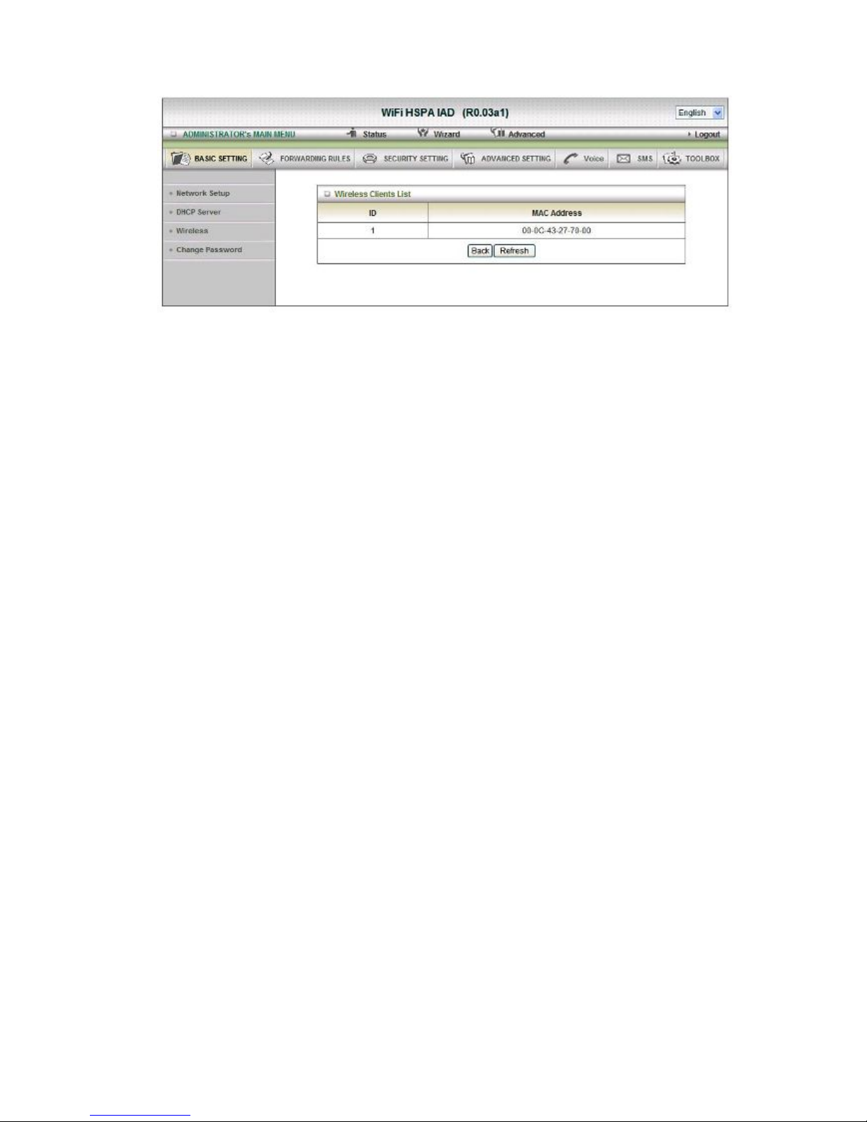
Wireless Client List
The list of wireless client is shows here.
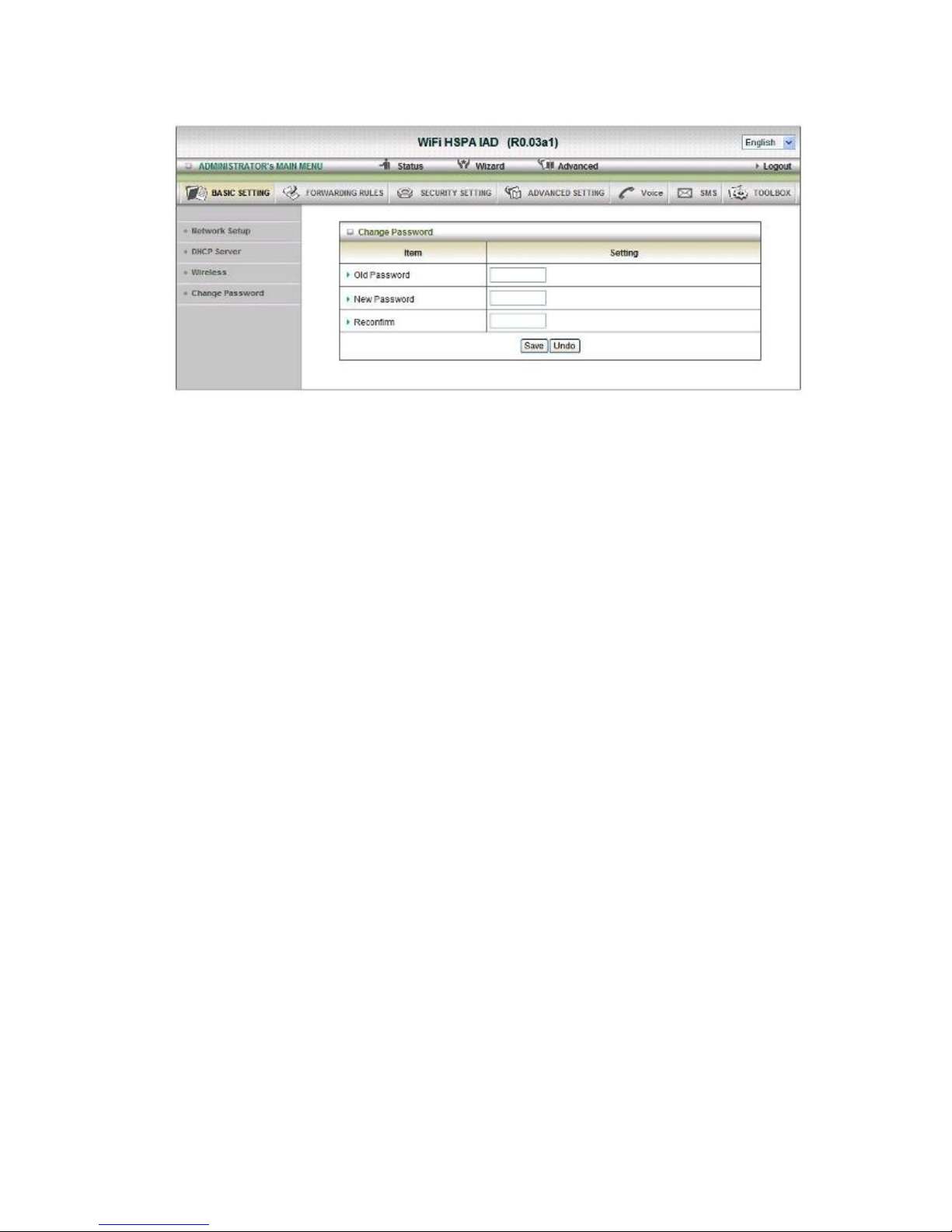
4.
Change Password
You can change Password here. We strongly recommend you to change the system
password for security reason.
Click on “Save” to store your setting or “Undo” to give up

2
.2.2 Forwarding Rules
Virtual Server
This product’s NAT firewall filters out unrecognized packets to protect your Intranet, so all
hosts behind this product are invisible to the outside world. If you wish, you can make some of
them accessible by enabling the Virtual Server Mapping.
A virtual server is defined as a Service Port, and all requests to this port will be redirected to
the computer specified by the Server I P. Virtual Server can work with Scheduling Rules,
and give user more flexibility on Access control. For Detail, please refer to Scheduling Rule.
For example, if you have an FTP server (port 21) at 192.168.123.1, a Web server (port 80) at
192.168.123.2, and a VPN server at 192.168.123.6, then you need to specify the following
virtual server mapping table:
Service Port
Server IP
Enable
21
192.168.12
3.1
V
80
192.168.12
3.2
V
1723
192.168.12
3.6
V
Click on “Save” to store your setting or “Undo” to give up
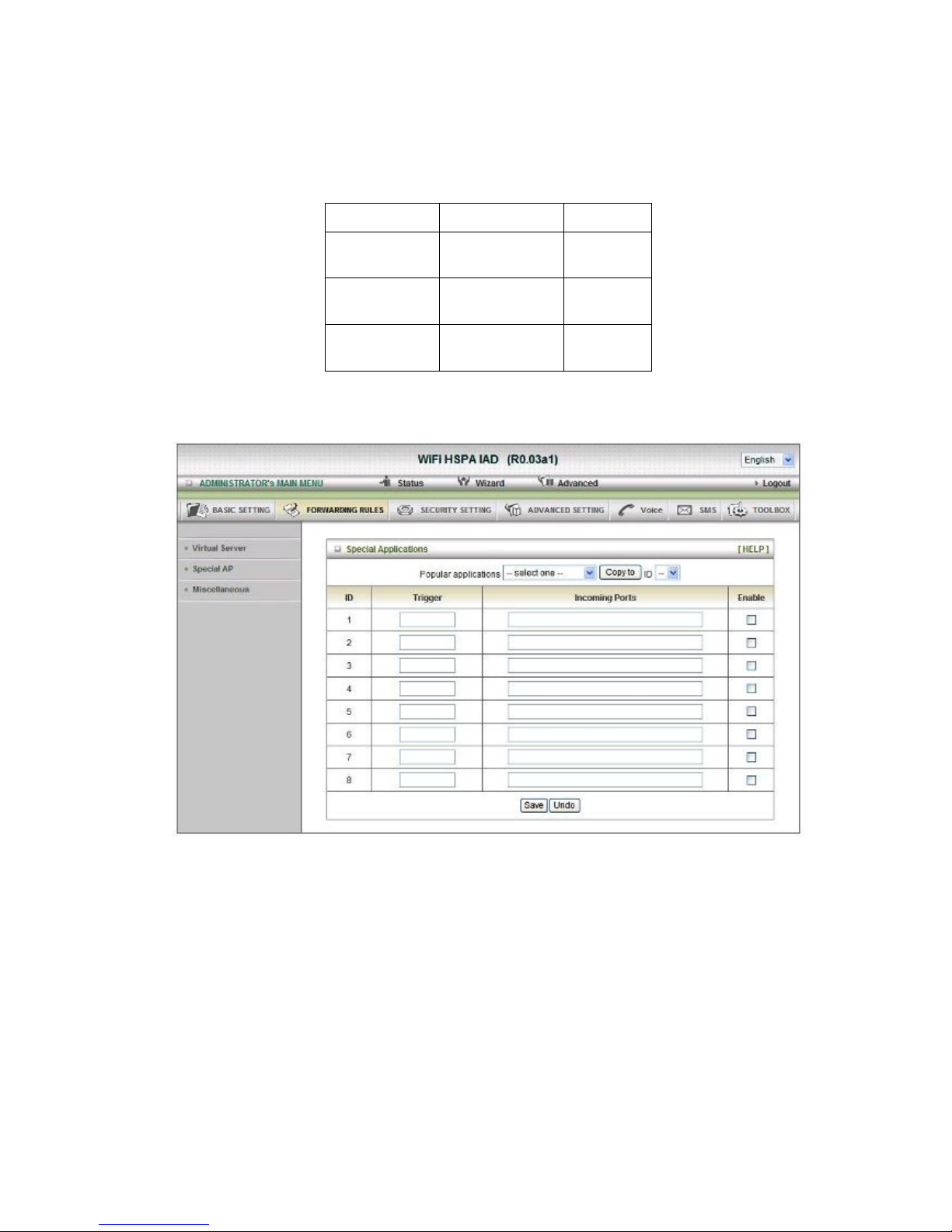
Special AP
Some applications require multiple connections, like Internet games, Video conferencing,
Internet telephony, etc. Because of the firewall function, these applications cannot work with a
pure NAT router. The Special Applications feature allows some of these applications to work
with this product. If the mechanism of Special Applications fails to make an application work,
try setting your computer as the DMZ host instead.
1. Trigger: the outbound port number issued by the application.
2. Incoming Ports: when the trigger packet is detected, the inbound packets sent to the
specified port numbers are allowed to pass through the firewall.
This product provides some predefined settings.
Select your application and Click “Copy to” to add the predefined setting to your list.
Click on “Save” to store your setting or” Undo” to give up
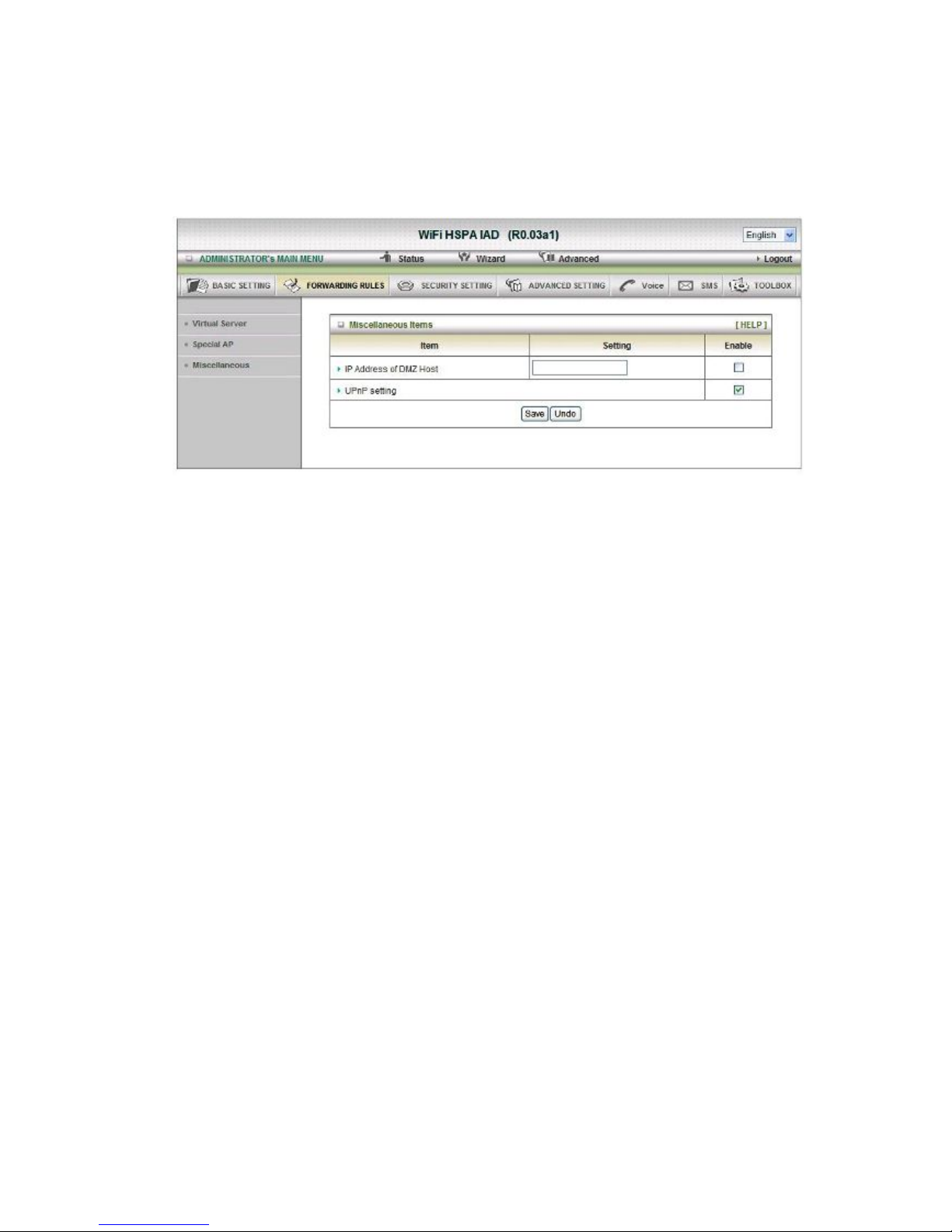
Miscellaneous
1. IP Address of DMZ Host
DMZ (Demilitarized Zone) Host is a host without the protection of firewall. It allows a
computer to be exposed to unrestricted 2-way communication for Internet games,
Video conferencing, Internet telephony and other special applications.
2. UPnP Setting
The device also supports this function. If the OS supports this function enable it, like
Windows X P. When the user gets IP from Device and will see icon as below:
Click on “Save” to store your setting or “Undo” to give up
2
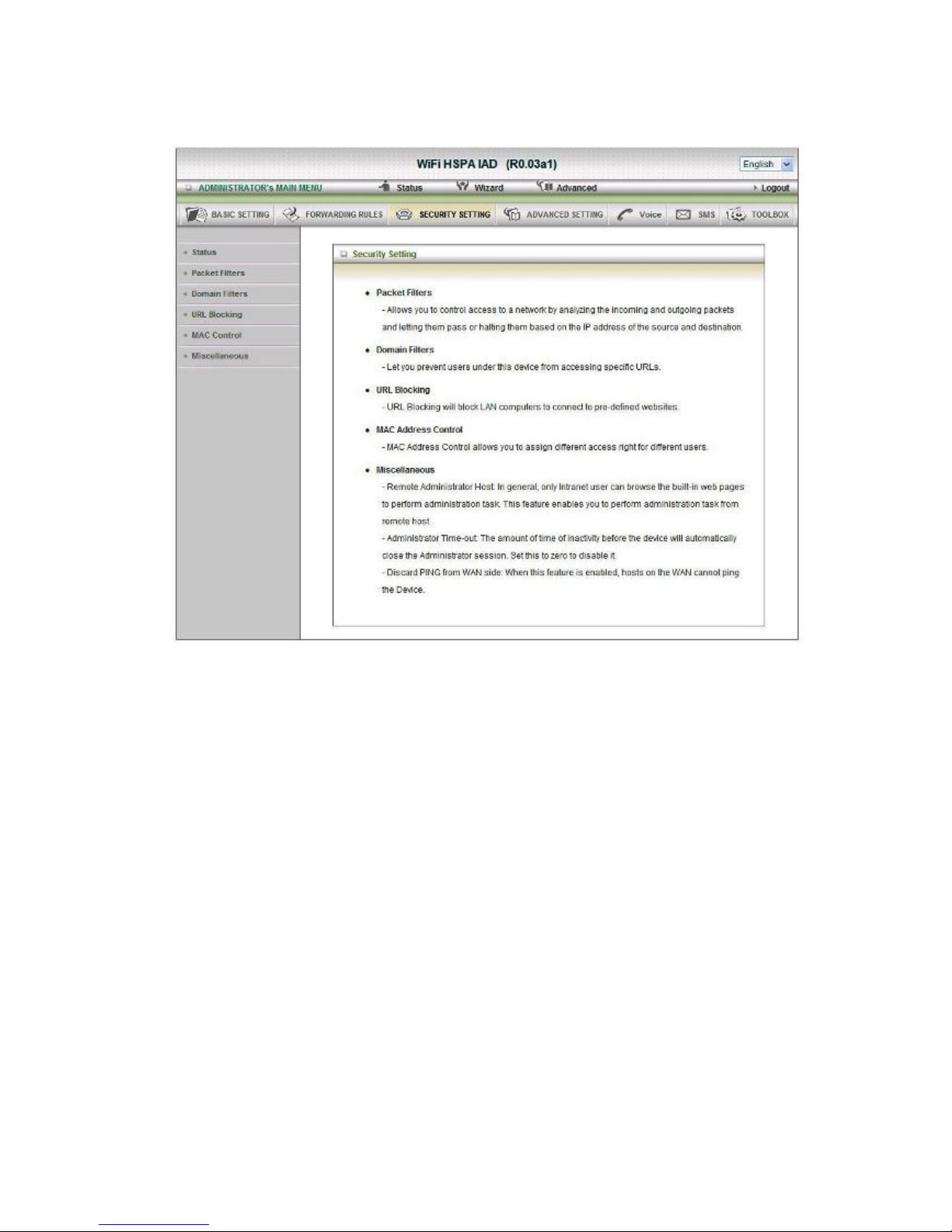
.2.3 Security Setting
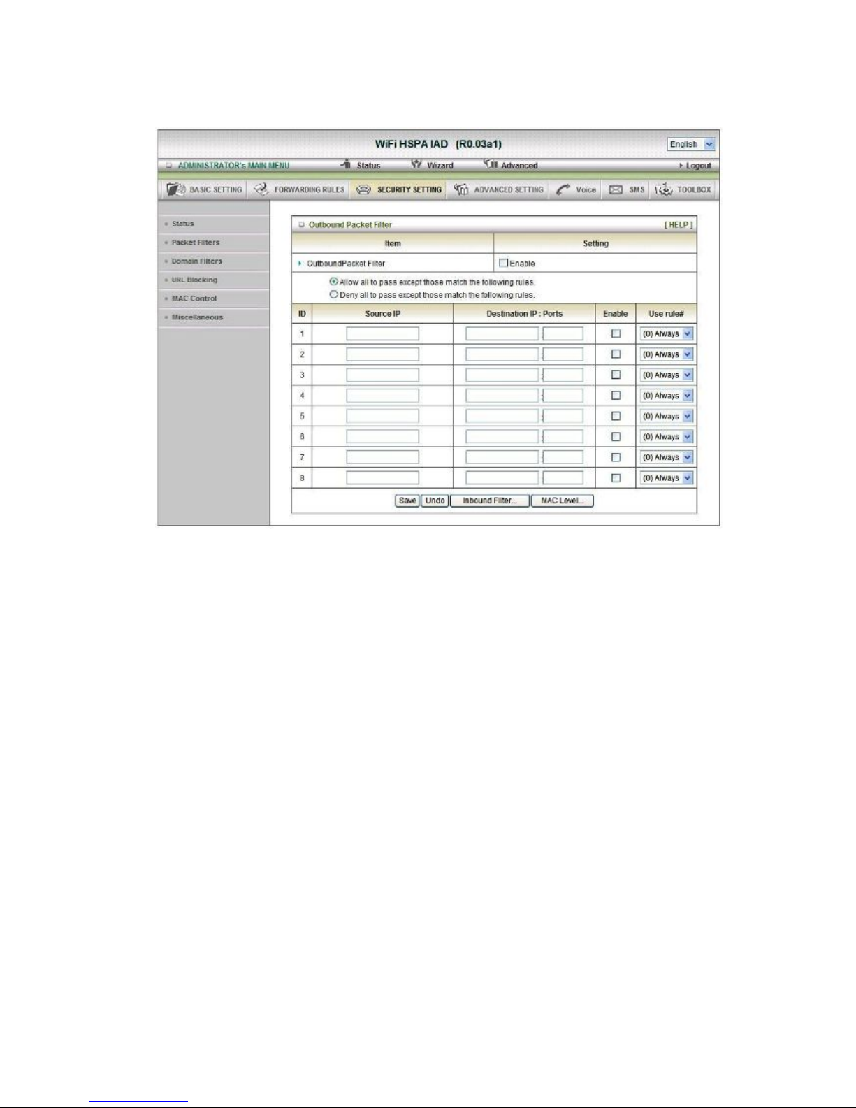
Packet Filters
Packet Filter includes both outbound filter and inbound filter. And they have same way to
setting.
Packet Filter enables you to control what packets are allowed to pass the router. Outbound
filter applies on all outbound packets. However, inbound filter applies on packets that destined
to Virtual Servers or DMZ host only. You can select one of the two filtering policies:
1. Allow all to pass except those match the specified rules
2. Deny all to pass except those match the specified rules
You can specify 8 rules for each direction: inbound or outbound. For each rule, you can define
the following:
• Source IP address
• Source port
• Destination IP address
• Destination port
• Protocol: TCP or UDP or both.
• Use Rule#
For source or destination IP address, you can define a single IP address (4.3.2.1) or a range of
IP addresses (4.3.2.1-4.3.2.254). An empty implies all IP addresses.

For source or destination port, you can define a single por
t (80) or a range of ports
(1000-1999). Add prefix "T" or "U" to specify TCP or UDP protocol. For example, T80, U53,
U2000-2999, No prefix indicates both TCP and UDP are defined. An empty implies all port
addresses. Packet Filter can work with Scheduling Rules, and give user more flexibility on
Access control. For Detail, please refer to Scheduling Rule.
Each rule can be enabled or disabled individually.
Click on “Save” to store your setting or “Undo” to give up
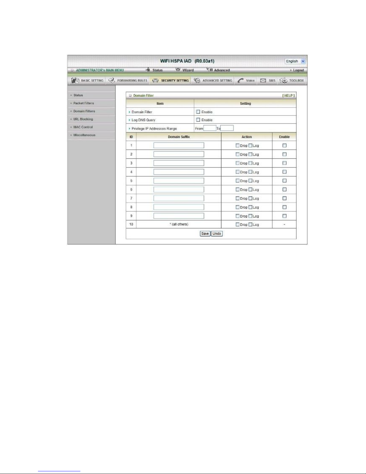
Domain Filters
1. Domain Filter
Let you prevent users under this device from accessing specific URLs.
2. Domain Filter Enable
Check if you want to enable Domain Filter.
3. Log DNS Query
Check if you want to log the action when someone accesses the specific URLs.
4. Privilege IP Address Range
Setting a group of hosts and privilege these hosts to access network without
restriction.
5. Domain Suffix
A suffix of URL can be restricted, for example, ".com", "xxx.com".
6. Action
When someone is accessing the URL met the domain-suffix, what kind of action you
want.
Check drop to block the access. Check “log” to log these access.
7. Enable
Check to enable each rule.
Click on “Save” to store your setting or “Undo” to give up

URL Blocking
URL Blocking will block LAN computers to connect with pre-define Websites. The major
difference between “Domain filter” and “URL Blocking” is Domain filter require user to input
suffix (like .com or .org, etc), while URL Blocking require user to input a keyword only. In other
words, Domain filter can block specific website, while URL Blocking can block hundreds of
websites by simply a keyword.
1. URL Blocking Enable
Check if you want to enable URL Blocking.
2. URL
If any part of the Website's URL matches the pre-defined word, the connection will be
blocked.
For example, you can use pre-defined word "sex" to block all websites if their URLs
contain pre-defined word "sex".
3. Enable
Check to enable each rule.
Click on “Save” to store your setting or “Undo” to give up

MAC Control
MAC Address Control allows you to assign different access right for different users and to
assign a specific IP address to a certain MAC address.
1. MAC Address Control
Check “Enable” to enable the “MAC Address Control”. All of the settings in this page
will take effect only when “Enable” is checked.
2. Connection control
Check "Connection control" to enable the controlling of which wired and wireless
clients can connect with this device. If a client is denied to connect with this device, it
means the client can't access to the Internet either. Choose "allow" or "deny" to allow
or deny the clients, whose MAC addresses are not in the "Control table" (please see
below), to connect with this device.
3. Association control
Check "Association control" to enable the controlling of which wireless client can
associate to the wireless LAN. If a client is denied to associate to the wireless LAN, it
means the client can't send or receive any data via this device. Choose "allow" or
"deny" to allow or deny the clients, whose MAC addresses are not in the "Control
table", to associate to the wireless LAN
Click “Save” to store your setting or “Undo” to give up

Miscellaneous
1. Administrator Time-out
The time of no activity to logout automatically, you may set it to zero to disable this
feature.
2. Remote Administrator Host/Port
In general, only Intranet user can browse the built-in web pages to perform
administration task. This feature enables you to perform administration task from
remote host. If this feature is enabled, only the specified IP address can perform
remote administration. If the specified IP address is 0.0.0.0, any host can connect with
this product to perform administration task. You can use subnet mask bits "/nn"
notation to specified a group of trusted IP addresses for example, "10.1.2.0/24".
NOTE: When Remote Administration is enabled, the web server port will be shifted to
80. You can change web server port to other port, too.
3. Discard PING from WAN side
When this feature is enabled, any host on the WAN cannot ping this product.
4. DoS Attack Detection
When this feature is enabled, the router will detect and log the DoS attack comes from
the
Internet. Currently, the router can detect the following DoS attack: SYN Attack,
WinNuke,
Port Scan, Ping of Death, Land Attack etc.
Click on “Save” to store your setting or” Undo” to give up

2
.2.4 Advanced Settings

System Log
This page support two methods to export system logs to specific destination by means of
syslog (UDP) and SMTP(TCP). The items you have to setup including:
IP Address for Sys log
Host IP of destination where sys log will be sent to.
Check Enable to enable this function.
Setting of E-mail Alert
Check if you want to enable Email alert (send syslog via email).
SMTP Server IP and Port
Input the SMTP server IP and port, which are connected with ':'. If you do not specify port
number, the default value is 25.
For example, "mail.your_url.com" or "192.168.1.100:26".
SMTP Username and Password
Input a user account and password for the SMTP server.
E-mail address
The recipients who will receive these logs, you can assign more than 1 recipient, using ';' or ','
to separate these email addresses.
E-mail Subject
The subject of email alert, this setting is optional.
View Log…
Reference the section Toolbox/System Info.
Click on “Save” to store your setting or “Undo” to give up

Dynamic DNS
To host your server on a changing IP address, you have to use dynamic domain name service
(DDNS).
So that anyone wishing to reach your host only needs to know the name of it. Dynamic DNS
will map the name of your host to your current IP address, which changes each time you
connect your Internet service provider.
Before you enable Dynamic DNS, you need to register an account on one of these Dynamic
DNS servers that we list in provider field.
To enable Dynamic DNS click the check box next to Enable in the DDNS field.
Next you can enter the appropriate information about your Dynamic DNS Server.
You have to define:
Provider
Host Name
Username/E-mail
Password/Key
You will get this information when you register an account on a Dynamic DNS server.
Click on “Save” to store your setting or “Undo” to give up

QOS
Provide different priority to different users or data flows, or guarantee a certain level of performance.
Enable
This Item enables QoS function or not.
Bandwidth of Upstream
Set the limitation of upstream speed.
Local: IP
Define the Local IP address of packets here.
Local: Ports
Define the Local port of the packets in this field.
Remote: IP
Define the Remote IP address of packets here.
Remote: Ports
Define the Remote port of the packets in this field.
QoS Priority
This defines the priority level of the current Policy Configuration. Packets associated with this
policy will be serviced based upon the priority level set. For critical applications High or Normal
levels are recommended. For non-critical applications select a Low level.
User Rule#
The QoS item can work with Scheduling Rule number#. Please reference the section
Advanced setting/schedule Rule.
Click on “Save” to store your setting or “Undo” to give up

SNMP
In brief, SNM P, the Simple Network Management Protocol, is a protocol designed to give a
user the capability to remotely manage a computer network by polling and setting terminal
values and monitoring network events.
Enable SNMP
You must check Local, Remote or both to enable SNMP function. If Local is checked, this
device will response request from LAN. If Remote is checked, this device will response
request from WAN.
Get Community
Setting the community of GetRequest your device will response.
Set Community
Setting the community of SetRequest your device will accept.
IP 1, IP 2, IP 3, IP 4
Input your SNMP Management PC’s IP here. User has to configure to where this device
should send SNMP Trap message.
SNMP Version
Please select proper SNMP Version that your SNMP Management software supports.
WAN Access IP Address
If the user wants to limit to specific the IP address to access, please input in the item. The
default 0.0.0.0 and means every IP of Internet can get some information of device with SNMP
protocol.
Click on “Save” to store your setting or “Undo” to give up.
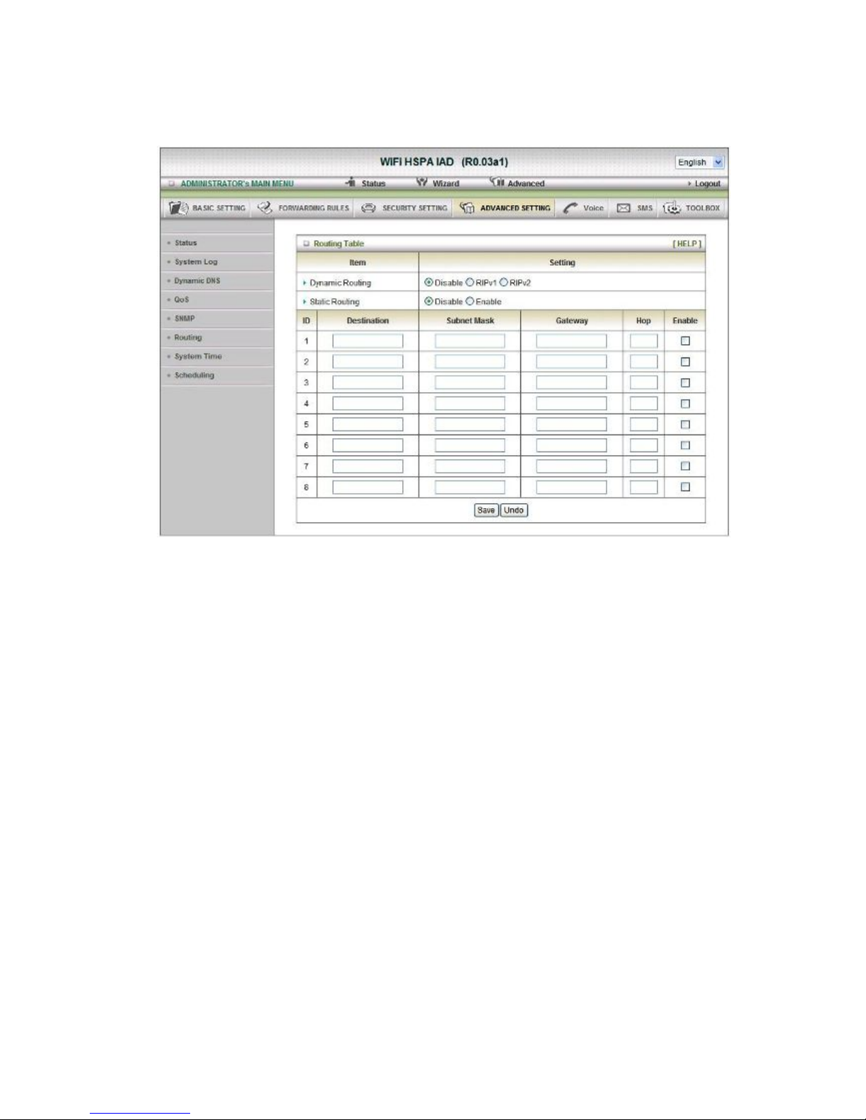
Routing
Routing Tables
Allow you to determine which physical interface address to use for outgoing IP data grams. If
you have more than one routers and subnets, you will need to enable routing table to allow
packets to find proper routing path and allow different subnets to communicate with each
other.
Routing Table settings are settings used to setup the functions of static and dynamic routing.
Dynamic Routing
Routing Information Protocol (RIP) will exchange information about destinations for computing
routes throughout the network. Please select RIPv2 only if you have different subnet in your
network. Otherwise, please select RIPv1 if you need this protocol.
Static Routing
For static routing, you can specify up to 8 routing rules. You can enter the destination IP
address, subnet mask, gateway, hop for each routing rule, and then enable or disable the rule
by checking or un-checking the Enable checkbox.
Click on “Save” to store your setting or “Undo” to give up.
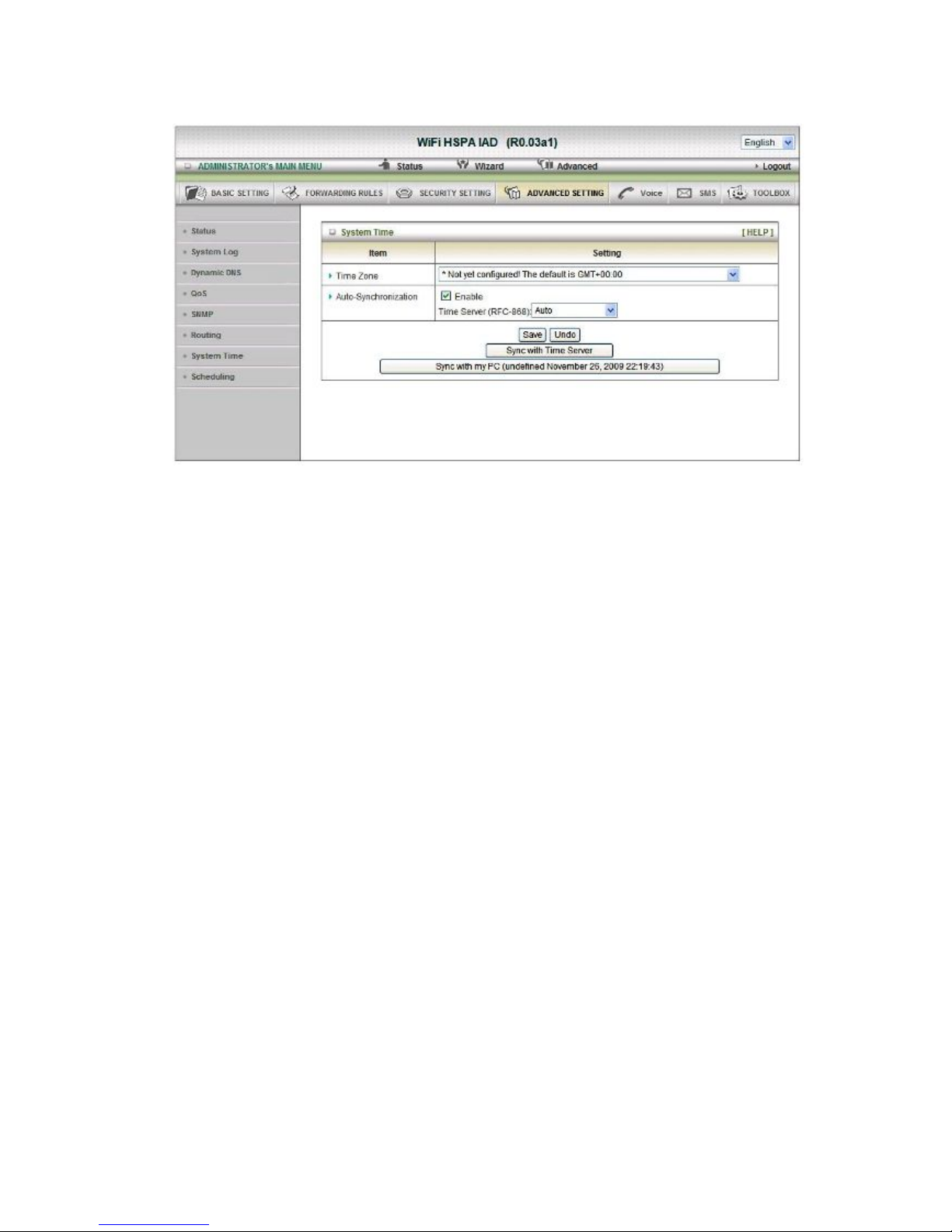
System Time
Time Zone
Select a time zone where this device locates.
Auto-Synchronization
Select the “Enable” item to enable this function.
Time Server
Select a NTP time server to consult UTC time
Sync with Time Server
Select if you want to set Date and Time by NTP Protocol.
Sync with my PC
Select if you want to set Date and Time using PC’s Date and Time
Click on “Save” to store your setting or “Undo” to give up.
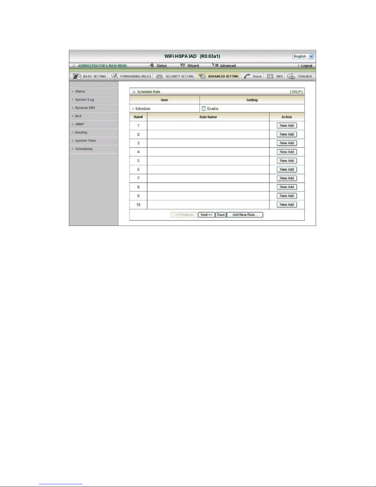
Scheduling
You can set the schedule time to decide which service will be turned on or off.
Select the “Enable” item. Press “Add New Rule” You can write a rule name and set which day
and what time to schedule from “Start Time” to “End Time”. The following example configure
“ftp time” as everyday 14:10 to 16:20

Click on “Save” to store your setting.

2.2.6 SMS
Create Message
You can create a new SMS message on this page. After finishing content of message,
and filling with phone number of receiver(s), pressing send button to send this
message out. You can see “Send OK” if the new message has been sent successfully.
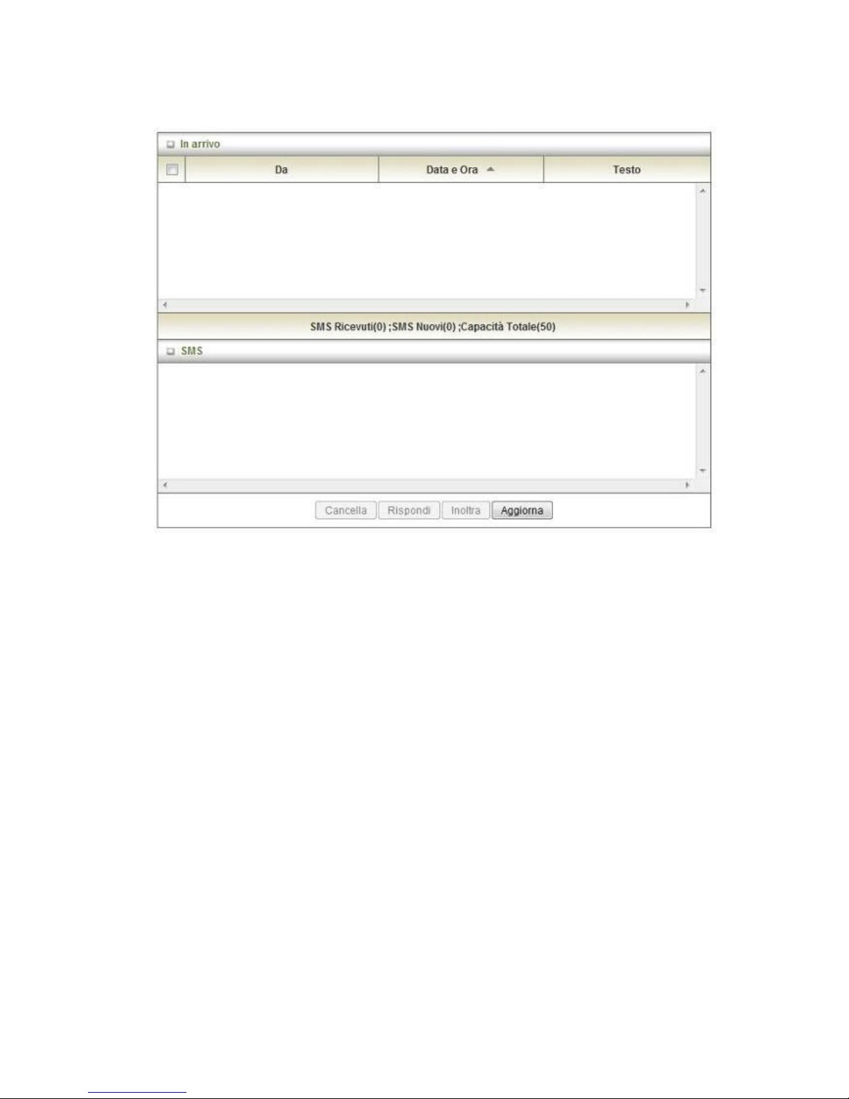
Inbox
You can read, delete, reply, and forward messages. Just click on one from the SMS
lists, then you can view the whole content of it in the SMS window below.
Refresh:
You can press “Refresh” button to renew SMS lists.
Delete, Reply, Forward Messages:
After reading message, you can check the checkbox on the left of each message to
delete, reply, or forward this message.

2.2.7 Tool Box
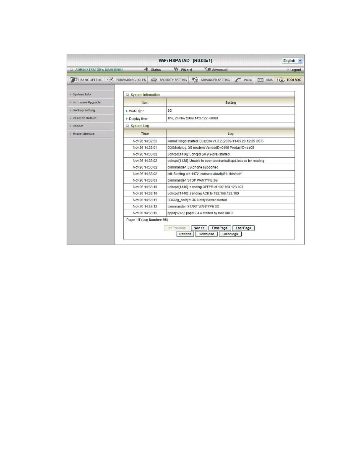
System Info
You can view the System Information and System log, and download/clear the System log, in
this page.

Firmware Upgrade
You can upgrade firmware by clicking “Upgrade” button.
Backup Setting
You can backup your settings by clicking the “Backup Setting” button and save it as a bin file.
Once you want to restore these settings, please click Firmware Upgrade button and use the
bin file you saved.

Reset to Default
You can also reset this product to factory default by clicking the Reset to default button.
Reboot
You can also reboot this it by clicking the Reboot button.

Miscellaneous
Domain Name or IP address for Ping Test
Allow you to configure an IP, and ping the device. You can ping a specific IP to test whether it
is alive.

Italy 21010 Cardano al Campo VA
via Alessandro Volta 39
http://www.digicom.it
 Loading...