

Digicel VM1510 Quick Start Manuals
ENG_3
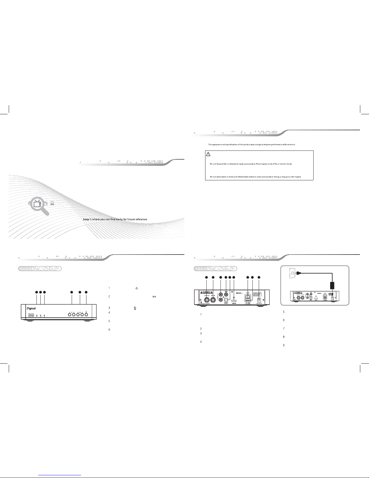
Front Panel
Power indicator (
)
The indicator light turns red when the power turns on.
Remote control signal sensor ( )
Do not block IR receiver, so that you can use the remote
CH
Channel Up/Down (up and down key)
VOL
Volume Up/Down (up and down key)
POWER
Switch the receiver power “ON” or “OFF”.
control properly.
Lock indicator ( )
Installation
QUICK START Guide
DIGICEL VM1510
Please read this installation guide carefully before you use this product and
ENG_1
2_ENG
Digicel is not responsible for problems caused by misuse of equipment.
Precaution
Place your product on a stable surface.
Do not drop or hit your product. This may cause a malfunction or injury.
Do not leave your product in too high or low temperature for a long time. Doing so may cause an explosion or an
electric shock.
Safety information
4_ENG
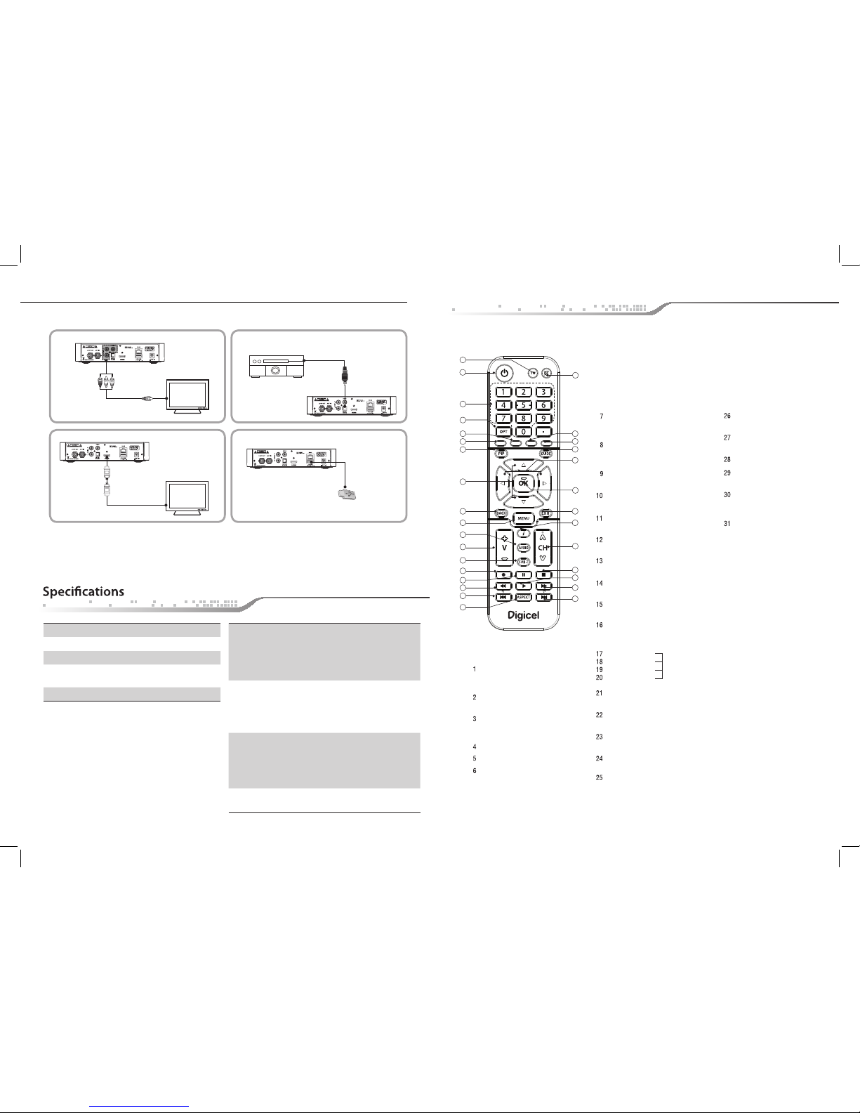
Installation
S/PDIF
HDMI
Connect a digital amplifer output.
Connect your decoder to an HDTV set with an HDMI cable
ETHERNET
Connect the LAN cable to Ethernet port.
USB
Connect the USB memory device to USB port
DC 12V IN
To connect your decoder to the main power supply.
LOOP OUT
Used to connect an antenna signal from the receiver
to either the antenna input jack on your television or
to another receiver.
CVBS
Video connection port to the TV or other equipment.
AUDIO
Audio connection port to the TV or other equipment.
ANT IN
DC 12V Power connection
Rear Panel
Digicel is not responsible for problems caused by misuse of equipment.
Precaution
Place your product on a stable surface.
Do not drop or hit your product. This may cause a malfunction or injury.
Do not leave your product in too high or low temperature for a long time. Doing so may cause an explosion or an
electric shock.
Safety information
2 31 4 5 6 7 98
1 2 3 4 5 6
FCC STATEMENT
Caution : Any changes or modifications in construction of this device which are not expressly approved by the party responsible for
compliance could void the user's authority to operate the equipment.
This device complies with Part 15 of the FCC Rules. Operation is subject to the following two conditions:
(1) this device may not cause harmful interference, and
(2) this device must accept any interference received, including interference that may cause undesired operation.
Note : This equipment has been tested and found to comply with the limits for a Class B digital device, pursuant to part 15 of the FCC
Rules. These limits are designed to provide reasonable protection against harmful interference in a residential installation This equipment
generates, uses and can radiate radio frequency energy and, if not installed and used in accordance with the instructions, may cause harmful
interference to radio communications, However, there is no guarantee that interference will not occur in a particular installation. If this
equipment does cause harmful interference to radio or television reception, which can be determined by turning the equipment off and on,
the user is encouraged to try to correct the interference by one or more of the following measures:
- Reorient or relocate the receiving antenna.
- Increase the separation between the equipment and receiver.
- Connect the equipment into an outlet on a circuit different from that to which the receiver is connected.
- Consult the dealer or an experienced radio/TV technician for help.
Changes or modifications not expressly approved by the party responsible for compliance could void the user’s authority to operate the
equipment. Indoor use only.
3305-00550_MANUAL_DIGICEL_QUICK GUIDE_ENG_���.indd 1 2014-11-24 �� 1:29:06
This appliance and its antenna must not b e co-located or operation in conjunction with any other antenna or transmitter. A minimu m sep arat ion
distance of 20 ㎝ must be maintained between the antenna and the person for this appliance to satisf y th e R F exposure requirements
ENG_5
Audio system
Optical cable
TV
TV
HDMI cable
RCA cable
USB memory
device
Chipset Broadcom / BCM7584
Flash Memory 4MB NOR, 512MB NAND
Program DRAM 512MB DDR3
USB / IP (Automatic/manual)
F/W Upgrade
Wi-Fi
Embedded support 2T2R (802.11a/b/g/n,
2.4/5Ghz Selectable Band)
Codec
Video
- MPEG-2, MPEG-4/H.264/AVC
- Dual 1080i decode or 1080p60 decode
- Power (On: Red)
- IR Indicator (On: Yellow)
- Lock Indicator (On: Green)
Audio
USB 2.0
HDMI 1.3
RJ45
S/PDIF (Optical)
CVBS, Cable in & Loop
Size(W*H*D) 200mmx40mmx140mm
- AC-3 (Dolby Digital), Dolby Digital Plus
- MPEG-1 layers 1,2 and 3 (MP3)
Front Input
Connectors & LED
5 Keys
(CH+, CH-,Vol+, Vol -, Power)
3 LEDs
Rear Output
Connectors
Physical
Specication
ENG_6
STAND BY
To switch between operation
and stand by mode.
To select shortcuts in menu
or tv list, info banner.
OK
To conrm your choice.
VOLUME UP/DOWN
To increase or decrease the volume.
CHANNEL UP/DOWN
To change channel up and down.
BACK
Press to go on step back.
Play
Used for playing les.
FF
Used for fast forward.
Pre File
To play the pre le in pvr.
ASPECT
Next File
To play the next le in pvr.
AUDIO
To select the sound mode.
(Mono, Left, Right, Stereo)
SUB-T
To enable or disable subtitle or
change the channel list mode.
EXIT
To return the normal viewing mode from a menu.
OPT
To set the video output.
Switch to TP/Satellite in Search Setup.
Record
Saves the current channel to the external HDD.
Pause
Used for pausing les.
Stop
Used for stopping record or play.
REW
Used for rewinding.
Red button
Green button
Yellow button
Blue button
MUTE
To enable or disable audio.
NUMERIC BUTTONS
To select the channel and enter the
channel edit and PIN code.
TV
PIP
GUIDE
Activate the program guide (EPG)
in the window.
MENU
To display the Main Menu on the screen
or return to the previous menu.
i
Displays the information box in the
normal viewing mode.
Up/Down
To move up or down on the menu.
Left/Right
To move left or right on the menu.
1
2
12
13
7
4
5
11
3
9
6
8
15
22
18
28
31
23
19
26
25
20
29
14
16
21
24
27
30
10
17
Using the remote control
ENG_7
3305-00550_MANUAL_DIGICEL_QUICK GUIDE_ENG_���.indd 2 2014-11-24 �� 1:29:08
 Loading...