

Page 1
Cycling Computer
COMPLETE MANUAL
BCP-51W
BCP-51WH
BCP-52WA
BCP-52WAH
ENGLISH
Page 2
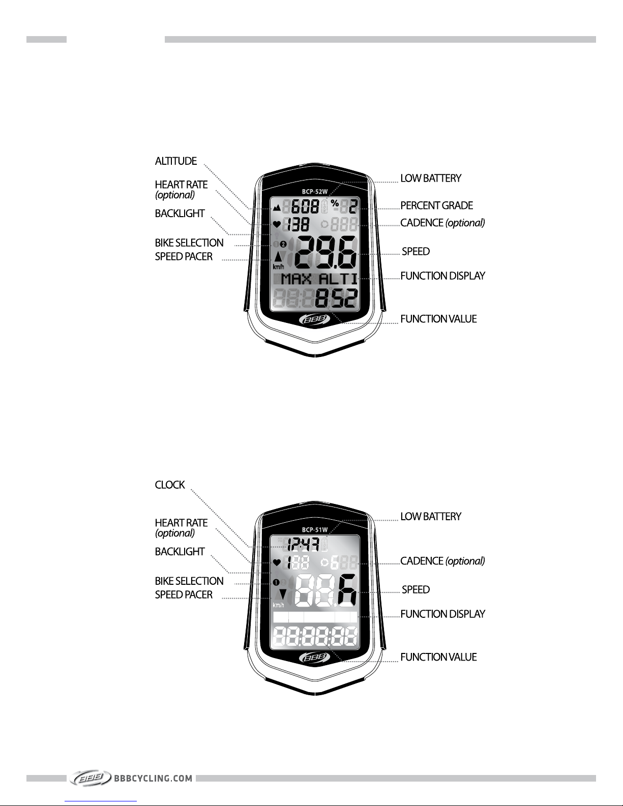
SCREEN ELEMENTS
SCREEN ELEMENTS
» BCP-52WA / BCP-52WAH
» BCP-51W / BCP-51WH
1
Page 3
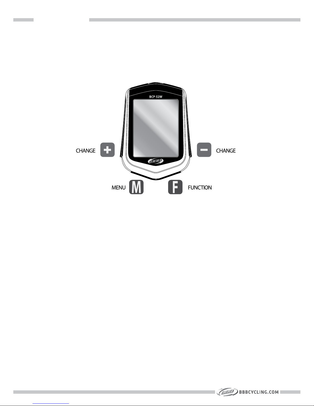
OPERATIONS BUTTON
OPERATIONS BUTTON
2
Page 4

CONTENTS
SECTION 1 : INSTALLATION
A Hardware: Mounting bracket, wheel magnet and speed sensor
B. Heart rate: Heart rate sensor set
C. Cadence: Cadence magnet and cadence sensor
SECTION 2 : FIRST TIME SET-UP
A. Battery installation
B. Settings
» Setting clock
» Setting heart rate values
» Setting gender
» Setting weight
» Setting wheel size
» Setting Km/h or M/h
» Setting odometer 1
» Setting total time 1
» Pairing
C. Setting home altitude
SECTION 3 : BEFORE EACH RIDE
» Trip data reset
» Home altitude calibration
SECTION 4 : ADVANCED SETTINGS
A. Second bike set-up
B. Advanced time settings
C. Advanced trip distance settings
D. Advanced heart rate settings
E. Advanced cadence settings
F. Advanced altitude settings
G. Temperature and Backlight
SECTION 5 : ADDITIONAL INFORMATION
A. Menu structure
B. Display elements
C. Functions overview
D. Troubleshooting
E. Technical specifications
5
6
7
9
10
11
12
13
14
15
15
16
16
17
19
20
22
23
24
25
26
27
28
30
30
31
32
32
Page 5

SECTION 1
INSTALLATION
Page 6
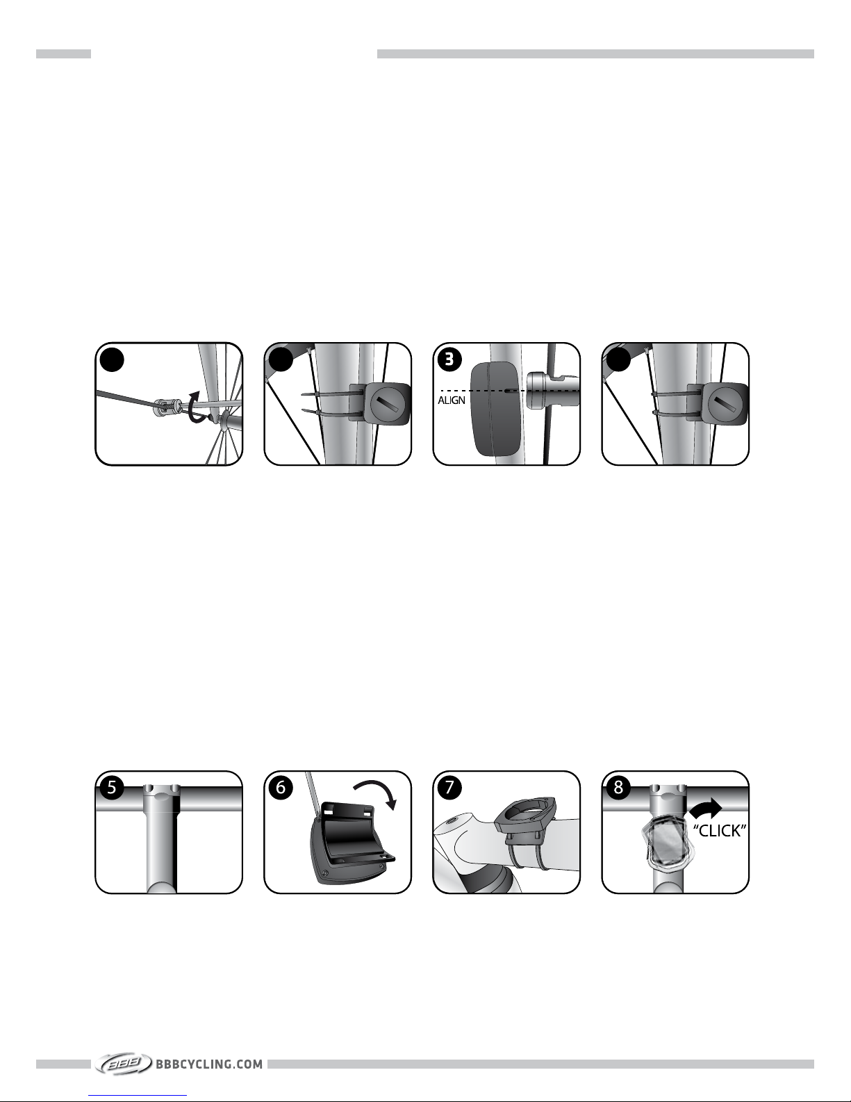
SECTION 1A : INSTALLATION - HARDWARE
1. Install the wheel magnet on a spoke, using a Phillips srewdriver.
2. Position the speed sensor on the fork leg to achieve the correct alignment with the wheel
magnet. If needed, move the wheel magnet. When you have achieved the correct alignment,
pass two zip-ties through the speed sensor and around the fork leg.
3. Re-check the alignment of the speed sensor, and tighten both zip-ties. The distance between
the wheel magnet and the sensor point should be maximum 5mm.
4. Cut off the excess length of the zip-ties.
INSTALLING THE WHEEL MAGNET AND SPEED SENSOR
1
2
4
5. The bracket can be installed on the stem as well as the handlebar. The bracket is pre-assembled in the handlebar position.
6. If you would like to have your computer on the stem, loosen the four screws on the bracket,
rotate the bracket 90 degrees and tighten the four screws.
7. Pass two zip-ties through the bracket and around the stem/handlebar. Cut off the excess
length of the zip-ties.
8. Place the BBB computer in the bracket and rotate clockwise till you hear a “click” sound.
INSTALLING THE COMPUTER BRACKET
5
Page 7
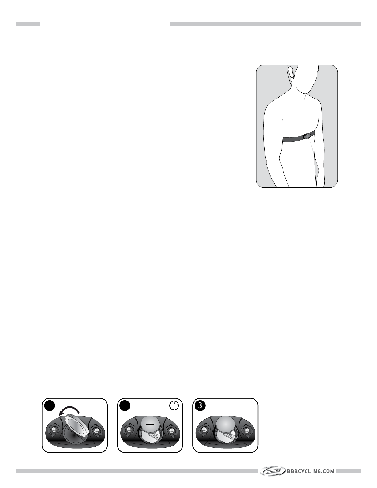
SECTION 1B : INSTALLATION - HEART RATE
The heart rate sensors are integrated in the soft elastic belt. For
a correct heart rate measurement, the belt must be positioned
slightly below your chest, directly on your skin.
1. Make the two contact areas moist before you start your exercise.
2. The chest belt needs to be snug to stay in place. Slide the
buckles to adjust the length of the belt for a snug but comfortable fit.
3. Press the ANT+ transmitter to the elastic belt on the two
push-button connectors.
Maintenance
- Remove the transmitter from the elastic belt after every use
and dry the push-buttons connectors on the transmitter.
Rinse the soft elastic belt under running water after every
use.
- Wash the elastic belt regularly in a washing machine at 30ºC.
Use a washing pouch. Do not spin-dry, iron, dry clean or
bleach the elastic belt. Do not use detergent with bleach or
fabric softener.
- Never put the transmitter in the washing machine!
INSTALLING THE HEART RATE SENSOR
The sensor batteries are pre-installed. When needed, check below illustrations for correct
replacement.
1. Open the battery cover by turning the cover counter clockwise.
2. Insert the battery (CR 2032) with the negative side (- ) facing up for 3 seconds. This will
reset the sensor.
3. Insert the battery (CR 2032) with the positive side (+ ) facing up. Close the battery cover
by turning it clockwise.
Batteries should be disposed of in compliance with local regulations.
» BATTERY REPLACEMENT FOR THE HEART RATE SENSOR
1
2
6
+
3s
Page 8
SECTION 1C : INSTALLATION - CADENCE
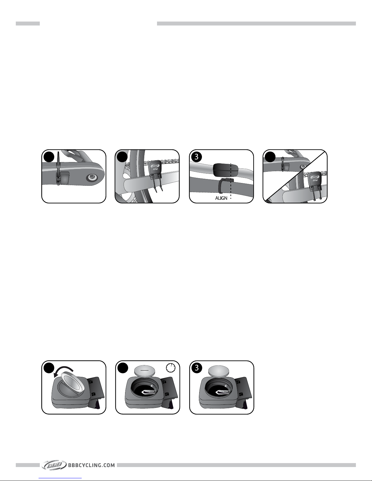
1. Install the cadence magnet on the non drive train side of the crank.
2. Install the cadence sensor on the chainstay.
3. Position the cadence sensor on the chainstay to achieve the correct alignment with the cadence magnet. If needed, move the cadence magnet. The distance between the magnet and
the sensor point should be maximum 3mm. When you have achieved the correct alignment,
pass two zip-ties through the sensor and around the chainstay.
4. Cut off the excess length of the zip-ties.
INSTALLING THE CADENCE MAGNET AND CADENCE SENSOR
1
2
4
The sensor batteries are pre-installed. When needed, check below illustrations for correct
replacement.
1. Open the battery cover by turning the cover counter clockwise.
2. Insert the battery (CR 2032) with the negative side (- ) facing up for 3 seconds. The will
reset the sensor.
3. Insert the battery (CR 2032) with the positive side (+ ) facing up. Close the battery cover
by turning it clockwise.
Batteries should be disposed of in compliance with local regulations.
» BATTERY REPLACEMENT FOR THE CADENCE SENSOR
7
1
2
+
3s
Page 9

SECTION 2
FIRST TIME SET-UP
Page 10
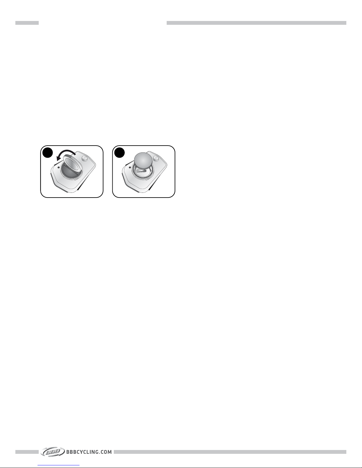
SECTION 2A : FIRST TIME SET-UP : BATTERY
1. Open the battery cover by turning the cover counter clockwise.
2. Insert the battery (CR 2032) with the positive side (+) facing up. Close the battery cover by
turning it clockwise
After the battery installation the first time setup menu will start automatically.
The first time setup procedure can be restarted by pressing the “AC” button on the back side the of
computer.
INSTALLING BATTERY INTO THE COMPUTER
1
+
2
9
Page 11
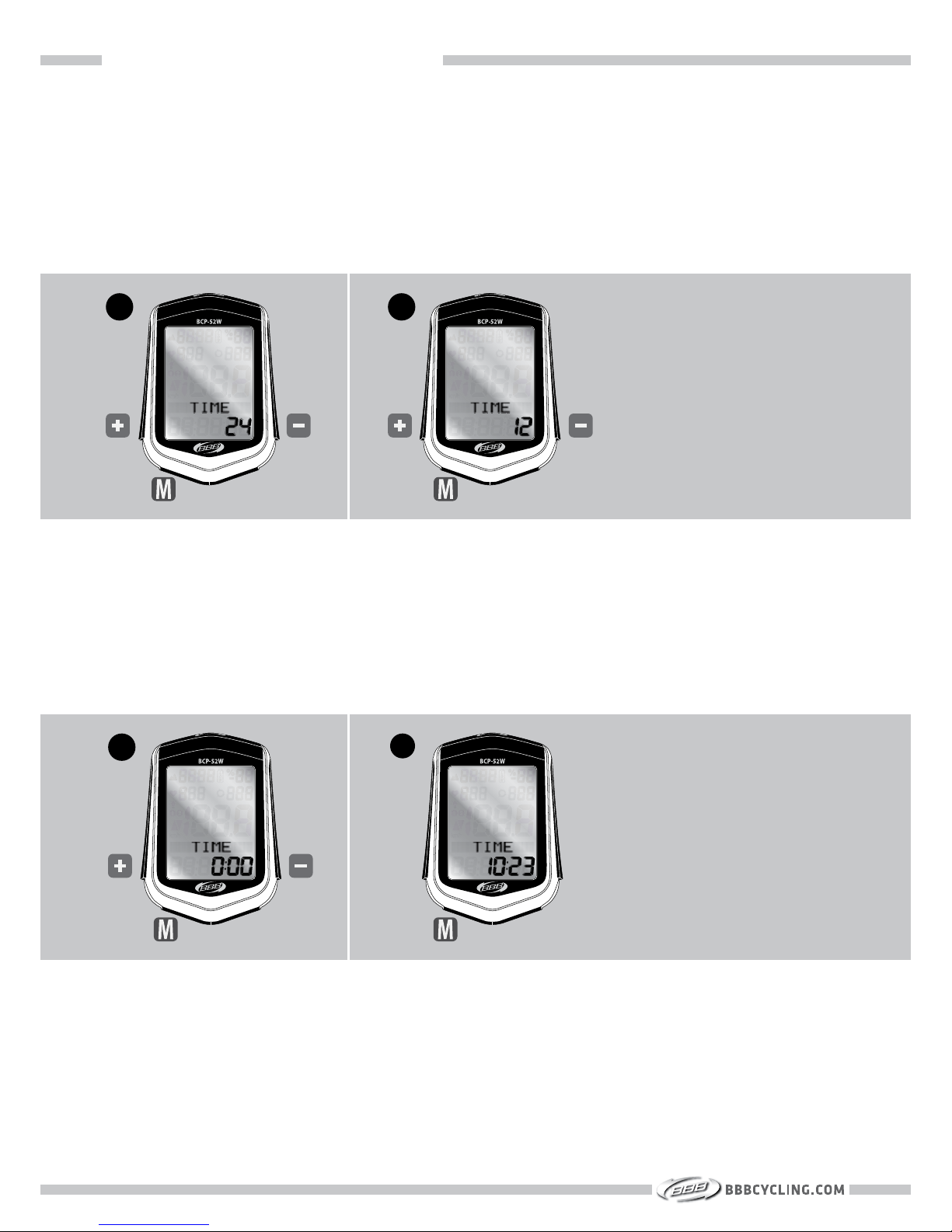
SECTION 2B : FIRST TIME SET-UP : SETTINGS
1. To change 24HR clock or 12HR clock, press + or -.
2. To select, press M.
SETTING CLOCK
1
2
3. To set the TIME press + or - .
4. To select, press M.
3
4
10
Page 12
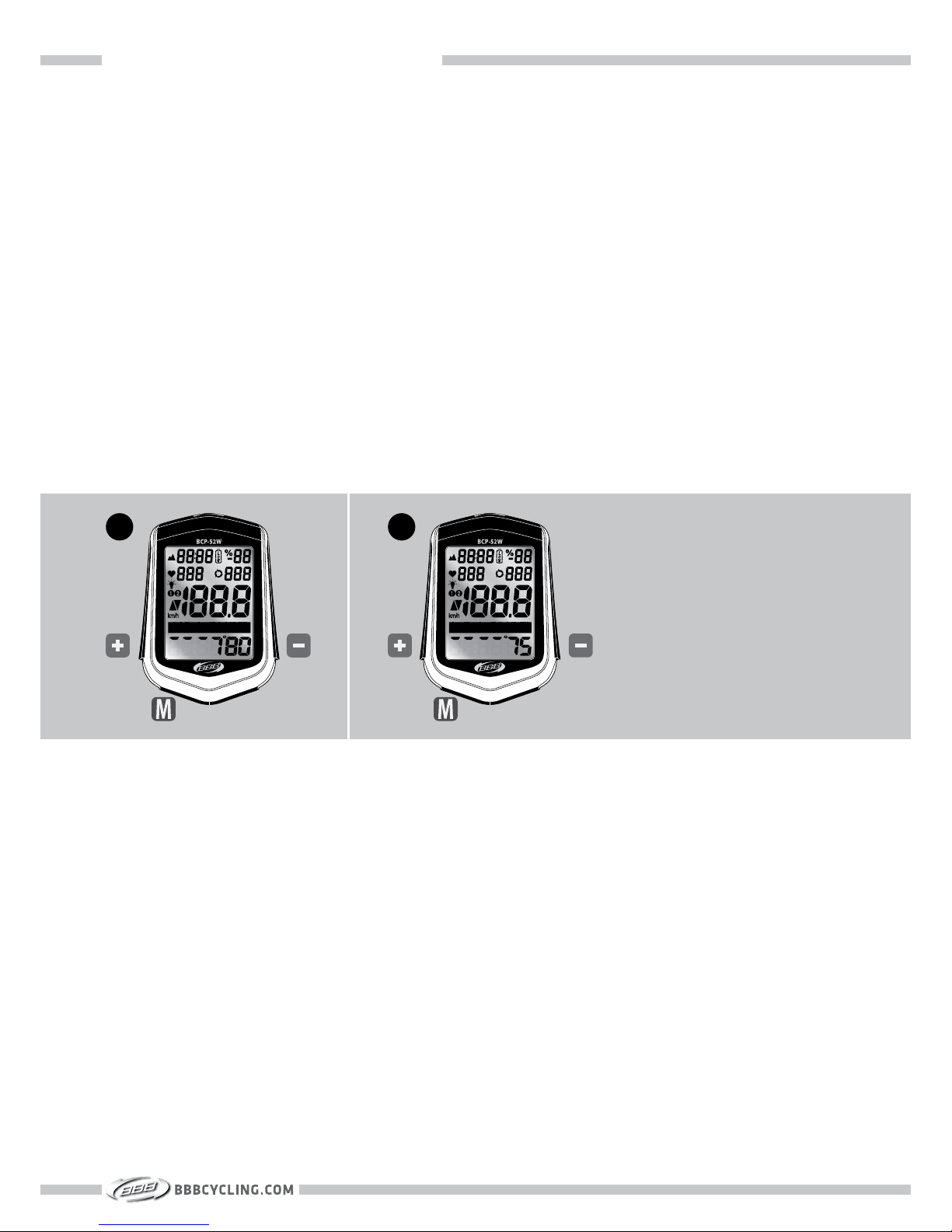
SECTION 2B : FIRST TIME SET-UP : SETTINGS
High Limit / Low Limit
For a healthy and effective training your heart rate should not be too high or too low. Your computer will warn you when you are training too hard or not hard enough. The heart rate shown on
the display will start to flash when you are under or over your limits.
During an exercise test done by a sports doctor your high and low heart rate limit can be determined precisely. There is a simple, less precise, way to determine these values:
High limit = (220(man) / 224(woman)) – age) x 90%
Low limit = (220(man) / 224(woman)) – age) x 60%
1. To set HI LIMIT press + or -. To select, press M.
2. To set LO LIMIT press + or - . To select, press M.
SETTING HEART RATE VALUES
1
2
11
Page 13
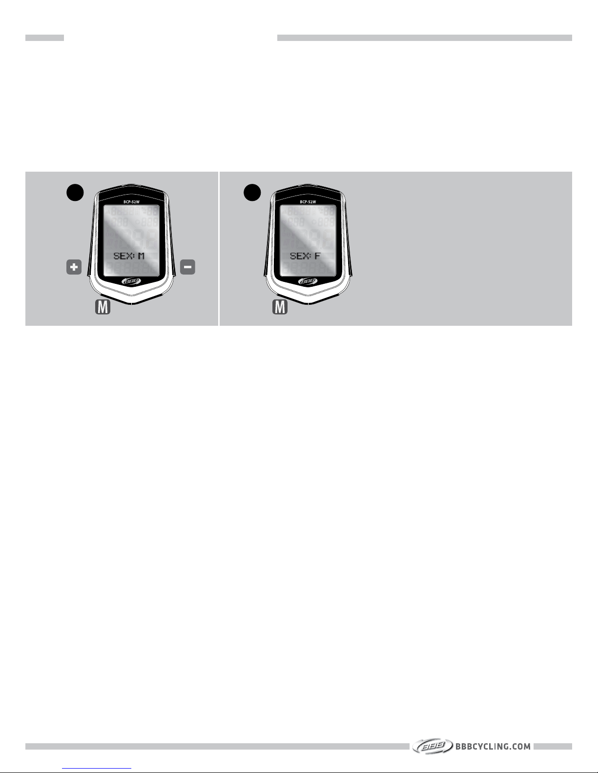
SECTION 2B : FIRST TIME SET-UP : SETTINGS
1. To set the SEX press + or - . (M = Male, F = Female).
2. To select, press M.
SETTING GENDER
1
2
12
Page 14
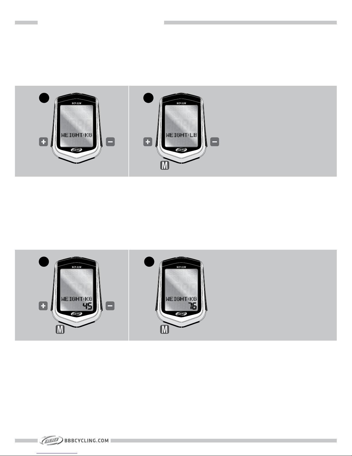
SECTION 2B : FIRST TIME SET-UP : SETTINGS
1. To change KG or LB, press + or -.
2. To select, press M.
SETTING WEIGHT
3. To set the WEIGHT press + or - .
4. To select, press M.
1
2
3
4
13
Page 15
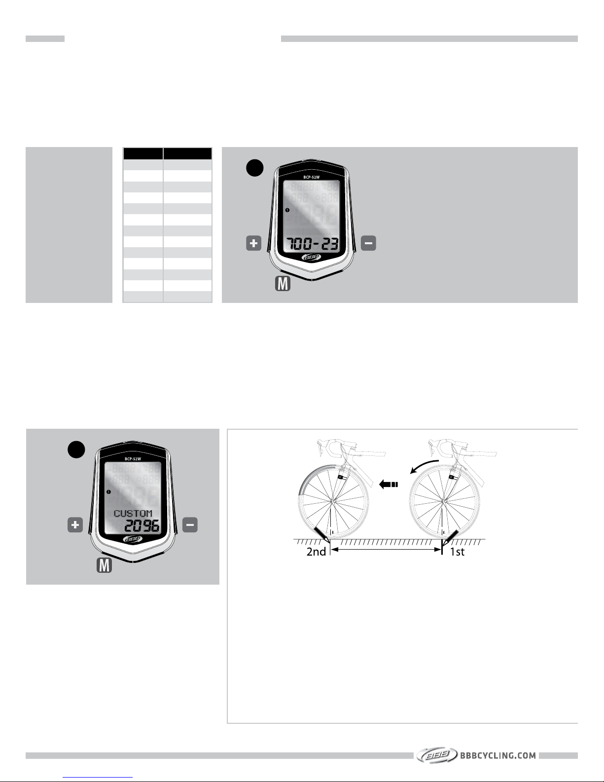
This computer has wheel size presets for easy wheel size selection.
1. To set the correct wheel size press + or -. To select, press M.
SETTING WHEEL SIZE
SETTING CUSTOM WHEEL SIZE
1. When the preferred wheel size is not listed in the preset list, select CUSTOM. To select,
press M.
To set the WHEEL SIZE digits press + or - . To select, press M. Repeat these steps to set the
other digits.
1
SECTION 2B : FIRST TIME SET-UP : SETTINGS
PRESET MM
700 700
700
700
700
700
26
26
26
26
26
26
CUSTOM
23 2096
25 2105
28 2136
32 2155
35 2168
38 2180
1.5 2010
1.9 2045
1.95 2050
2.0 2055
2.1 2068
2.2 2075
0000 - 3999
-
-
-
-
-
-
-
-
-
-
-
1
To set the most precise wheel size, do a “rollout” test.
(Make sure the tires are at the correct tire pressure)
A. Sit on the bicycle, place the valve of the front
wheel on the floor.
B. Mark the floor at the valve position.
C. While you sit on the bicycle, have a helper roll the
bicycle forward with one revolution of the wheel,
so that the valve is directly on the floor again.
D. Mark the new position of the valve.
E. Measure the distance between the two marks, in
millimeters.
F. Set this value in the DigiBoard computer.
14
Page 16
SECTION 2B : FIRST TIME SET-UP : SETTINGS
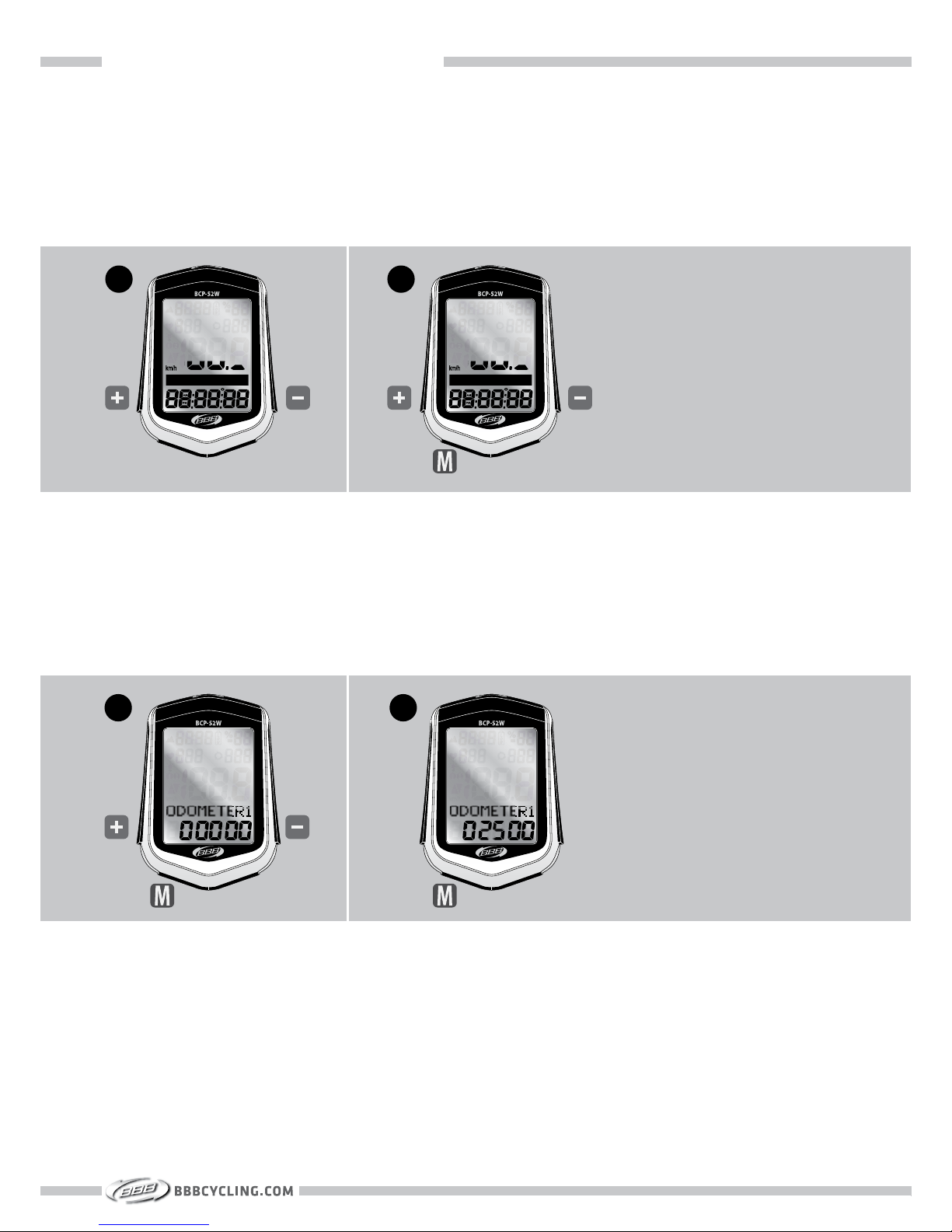
1. To change the SPEED UNIT to KM/H or M/H, press + or -.
2. To select, press M.
SETTING KM/H OR M/H
1
2
1. It is possible to set the ODOMETER data into your new bicycle computer. To select the first
digit, press + or -.
2. To select, press M. Repeat these steps to select the other digits.
SETTING ODOMETER 1
1
2
15
Page 17
SECTION 2B : FIRST TIME SET-UP : SETTINGS
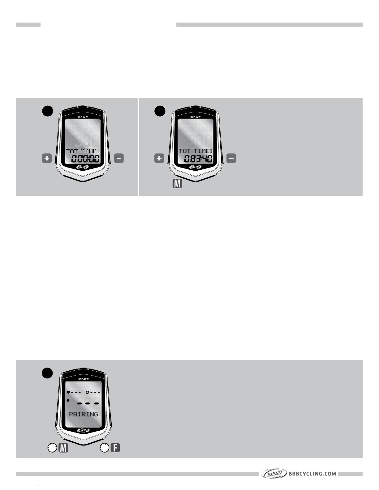
1. It is possible to set the TOTAL TIME data into your new bicycle computer. To select the first
digit, press + or -
2. To select, press M. Repeat these steps to select the other digits.
SETTING TOTAL TIME 1
1
2
1. During the pairing procedure the computer makes a secured digital connection with the
sensors. Once a sensor is found the computer will show “SPD FOUND”, “CAD FOUND” and/
or “HRT FOUND”, depending on the type of sensors you are using.
During the pairing process the heart rate, cadence and speed symbol will flash in the display. When a sensor is found, the symbol will stop flashing. Before you start using your bicycle
wait until the pairing process is completely finished and the computer display shows the main
screen.
Once sensors are paired the connection is stored in the computer memory. The pairing process
does not have to be repeated before each ride.
The pairing procedure can be repeated manually by pressing the M and F button together for 3
seconds.
Starting the pairing procedure manually is needed when sensors cannot be found or when a later
bought sensor needs to be paired.
PAIRING
1
3s 3s
16
Page 18
SECTION 2C : FIRST TIME SET-UP : HOME ALTITUDE
The altitude in this computer is measured by a pressure sensitive barometer. Not only altitude,
but also changing weather will influence the height showed on your computer.
Before each ride you have to calibrate the altitude to let the computer compare your home
altitude with the current weather situation.
Home altitude can also be described as start altitude. The home altitude is a saved preset for
easy calibration.
Are you on holiday?
Save your start altitude as home for calibration before each ride.
Will your ride start from a different altitude each day?
Check page 27, Advanced Altitude settings, for changing the current altitude.
Calibration of the altitude is described at page 20.
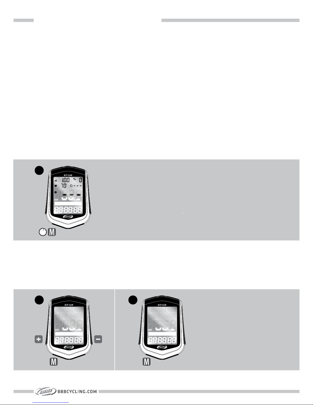
1. Start with the ALTITUDE menu (ALTI GAIN shown in display). Press M button for 3 seconds.
SETTING ALTITUDE (BCP-52WA / BCP-52WAH ONLY)
2. To set the ALTITUDE press + or -. To select, press M . Repeat to set the other digits.
3. To save the HOME ALTITUDE, press M to save the value.
SETTING HOME ALTITUDE (BCP-52WA / BCP-52WAH ONLY)
1
3s
Home altitude information for your specific position can be found by
various sources like maps, tourist information or on the internet.
2
3
17
Page 19

SECTION 3 : BEFORE EACH RIDE
SECTION 3
BEFORE EACH RIDE
Page 20
SECTION 3 : BEFORE EACH RIDE : TRIP DATA RESET
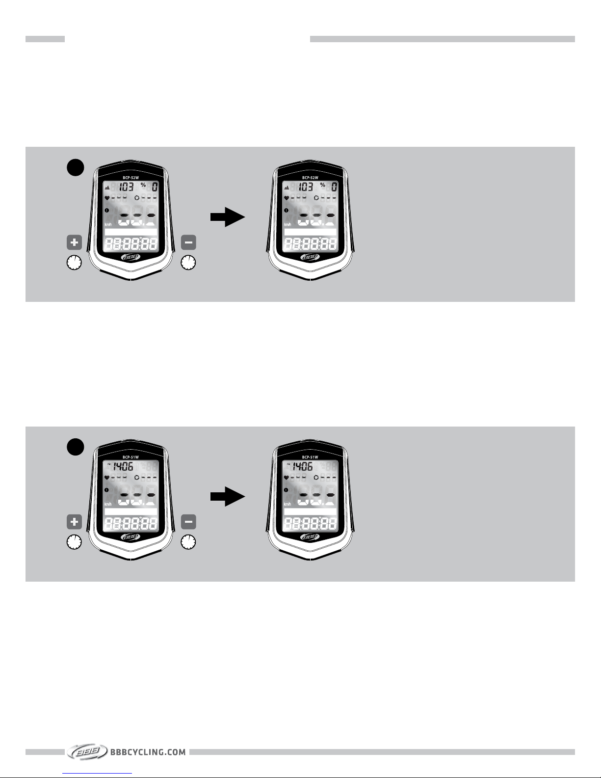
1. The TRIP data can be reset in any menu by pressing + and – button for 3 seconds.
Please note: Every trip related data is reset including CADENCE, HEART RATE and ALTITUDE.
Totals like ODO and TOTAL TIME will not be reset.
TRIP DATA RESET (BCP-52WA / BCP-52WAH ONLY)
1. The TRIP data can be reset in any menu by pressing + and – button for 3 seconds.
Please note: Every trip related data is reset including CADENCE and HEART RATE. Totals like
ODO and TOTAL TIME will not be reset.
TRIP DATA RESET (BCP-51W / BCP-51WH ONLY)
1
3s 3s
1
3s 3s
19
Page 21
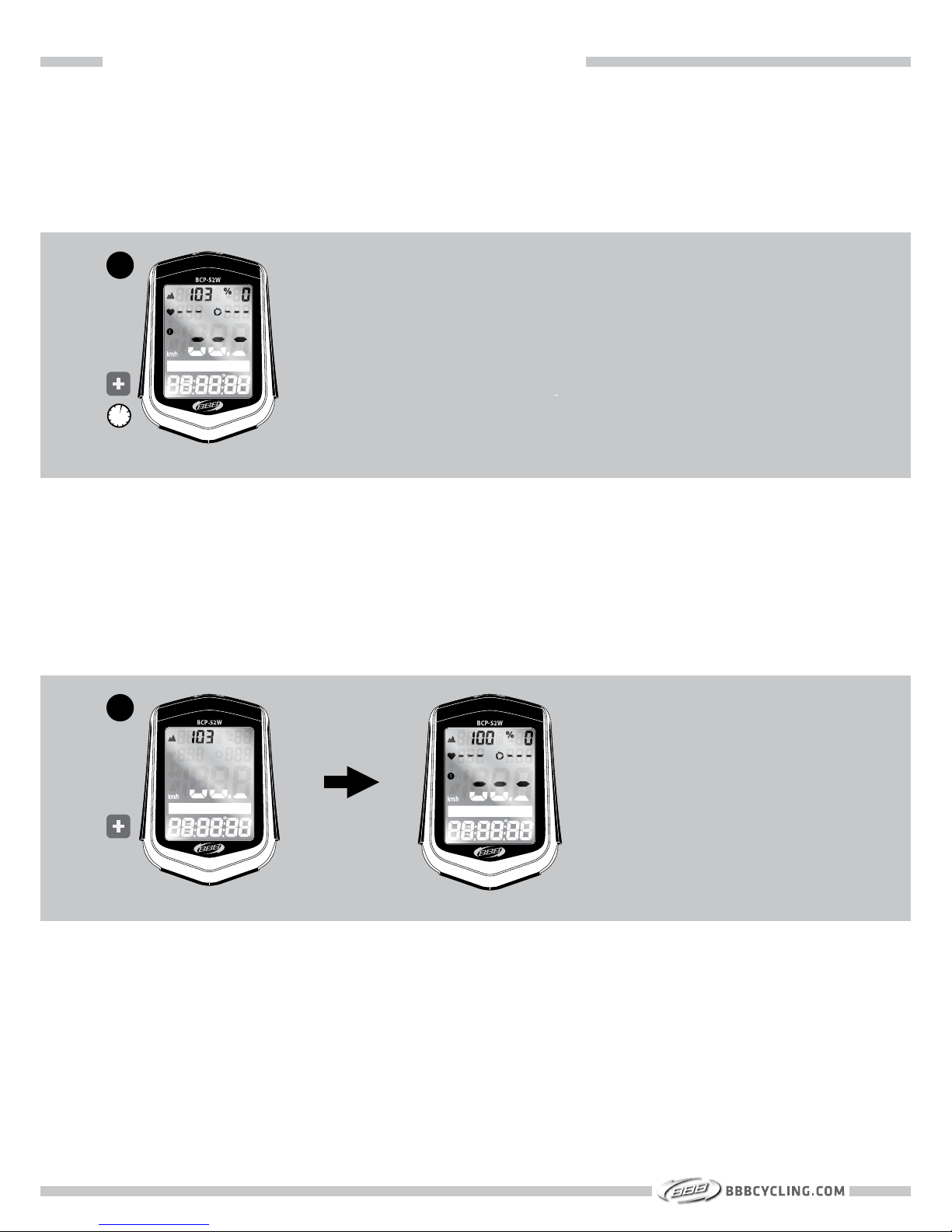
SECTION 3 : BEFORE EACH RIDE : HOME ALTITUDE CALIBRATION
1. Start with the ALTITUDE menu (ALTI GAIN shown in display). Press + button for 3 seconds.
HOME ALTITUDE CALIBRATION (BCP-52WA / BCP-52WAH ONLY)
1
2. Confirm the HOME ALTI by pressing the + button. The display will now show your home
ALTITUDE and is calibrated with the current weather situation.
3s
2
20
Page 22

SECTION 4 : ADVANCED SETTINGS
SECTION 4
ADVANCED SETTINGS
21
Page 23
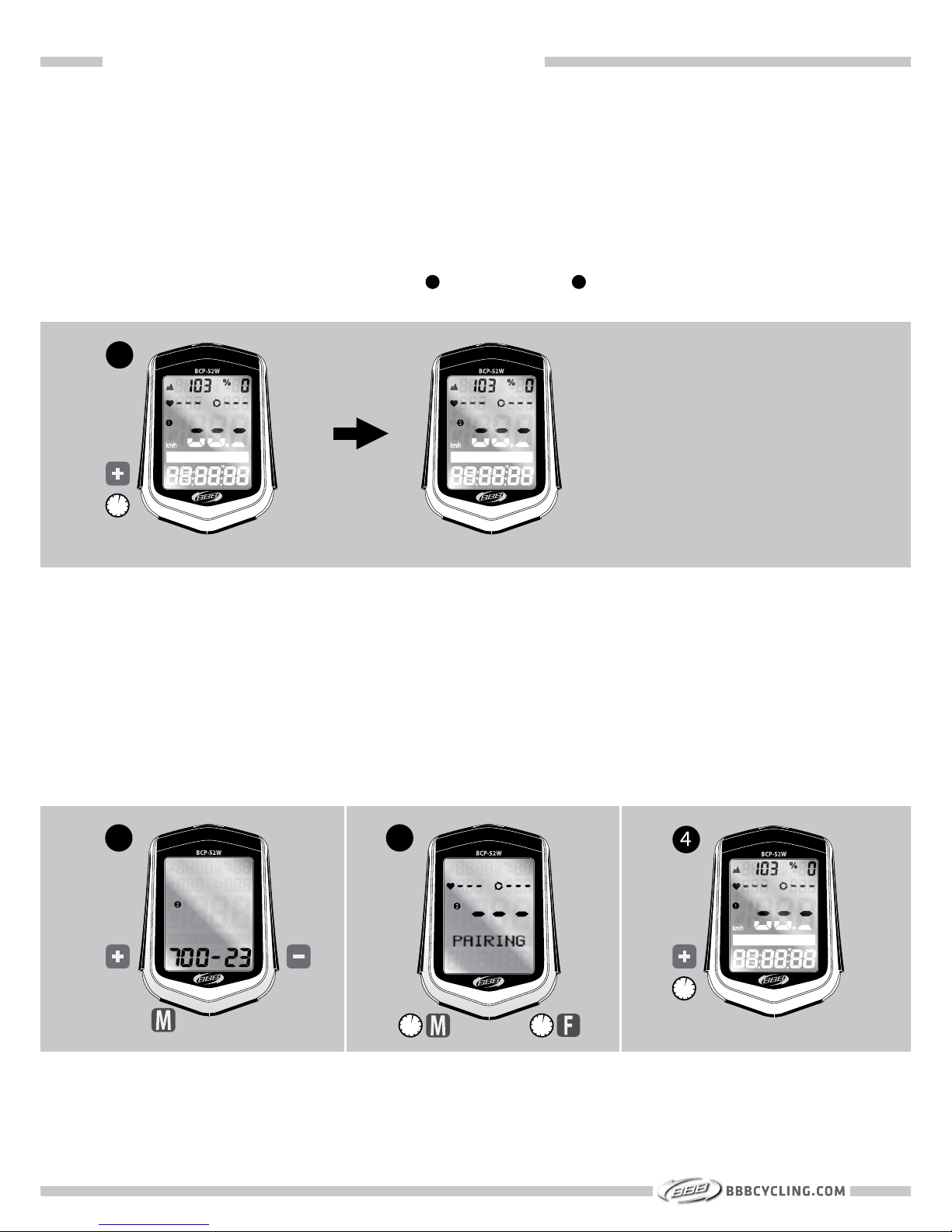
SECTION 4A : ADVANCED SETTINGS : SECOND BIKE SET-UP
Mount the bracket on your second bicycle as instructed on page 5.
Mount the wheel magnet and speed sensor on your second bicycle as instructed on page 5.
Mount the cadence magnet and sensor on your second bicycle as instructed on page 7.
1. Start with the DISTANCE menu (TRIP DIST shown in display). Press + button for 3 seconds.
The second bike is selected when the is changed into n the display.
SECOND BIKE SET-UP
2. Press the M button for 3 seconds for setting the wheel size. Follow the same procedure as
described on page 14.
3. Press M and F button for 3 seconds to start pairing with your second bike speed sensor and
cadence sensor (if applicable). Make sure the distance between bicycle 1 and bicycle 2 is at
least 10 meters.
4. To switch between bicycle 1 and bicycle 2, start with the DISTANCE menu (TRIP DIST shown
in display). Press + button for 3 seconds.
2
3
3s 3s
1
3s
3s
22
Page 24
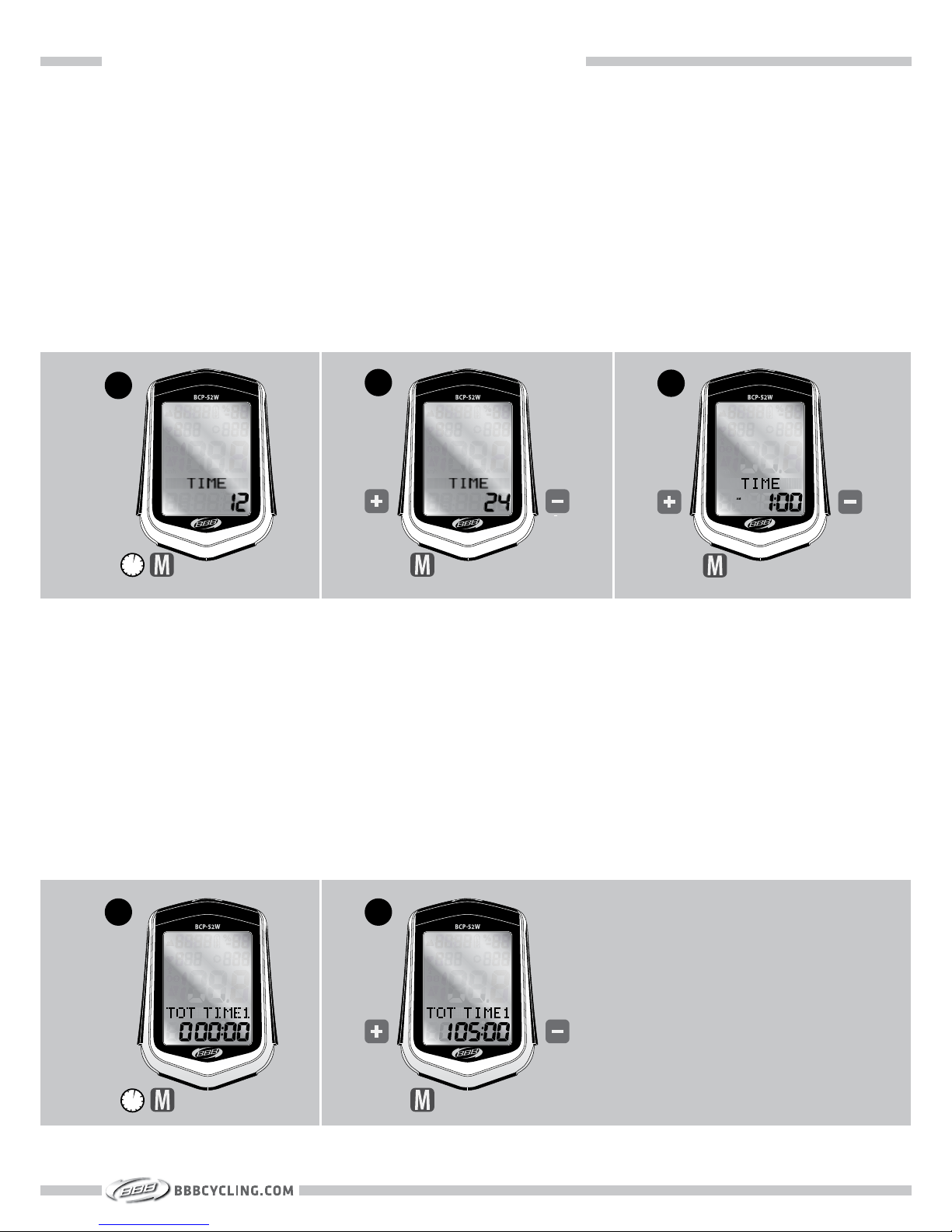
SECTION 4B : ADVANCED SETTINGS : ADVANCED TIME SETTINGS
The Time is set during the First-Time Set-Up, page 10.
1. To change the clock start with the TIME menu (TIME shown in display). Press M button for 3
seconds.
2. To change 24HR clock or 12HR clock, press + or - . To select press M.
3. To set the time press + or -. To select press M. Repeat these steps to set the other digits. If
the 12HR clock is selected, you must also select AM or PM.
TIME SET-UP
The Total Ride Time is set during the First-Time Set-Up, page 16.
1. To change this data start with the TIME menu (TOT TIME1 shown in display). Press M button for 3 seconds.
2. To select the first digit, press + or -. To select press M. Repeat these steps to select the
other digits.
To change the Total Ride Time for the second bike, repeat these step starting with TOT TIME2
shown in display.
SETTING TOTAL RIDE TIME
1
3
3s
2
3s
2
1
23
Page 25
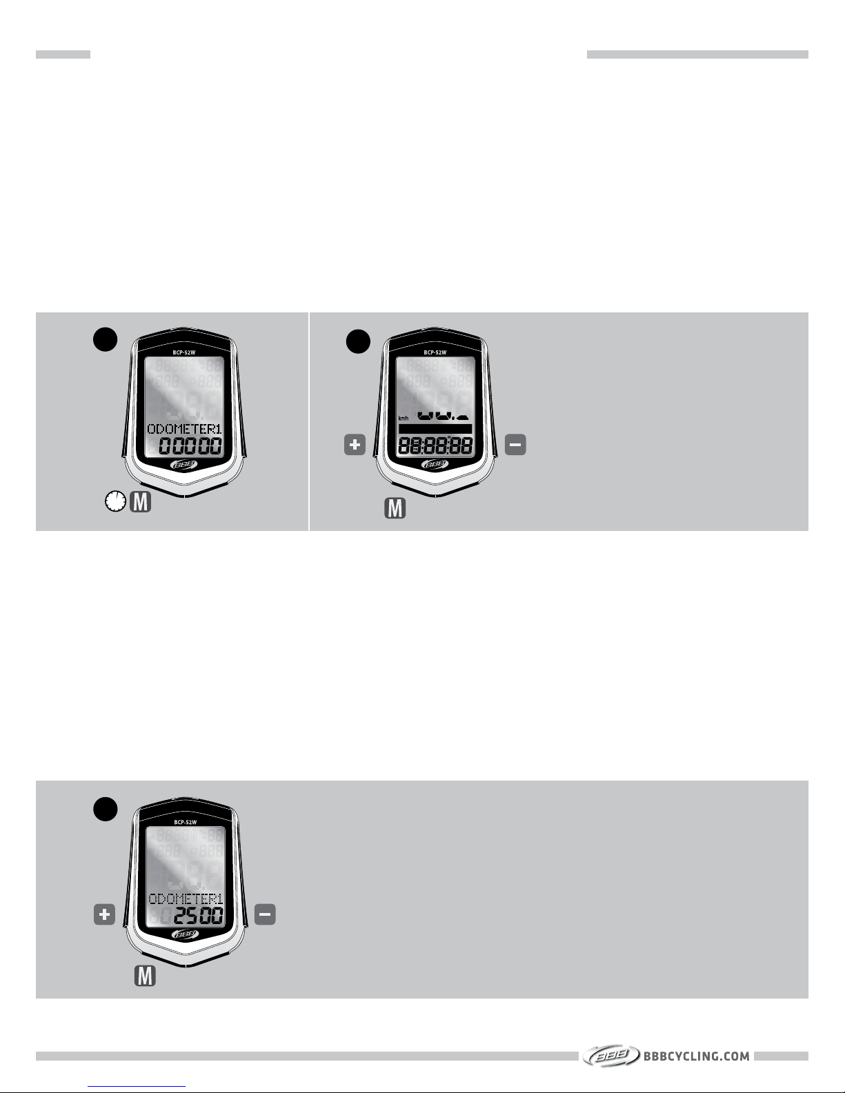
SECTION 4C : ADVANCED SETTINGS : ADVANCED TRIP DISTANCE SETTINGS
The Odometer is set during the First-Time Set-Up, page 15.
1. To change this data start with the DISTANCE menu (ODOMETER1 shown in display). Press M
button for 3 seconds.
2. To change the speed unit to KM/H or M/H, press + or -. To select press M.
ODOMETER SET-UP
3. To select the first digit, press + or -. To select press M. Repeat these steps to select the
other digits.
To change the odometer for the second bike, repeat these step starting with ODOMETER2
shown in display.
1
2
3s
3
24
Page 26
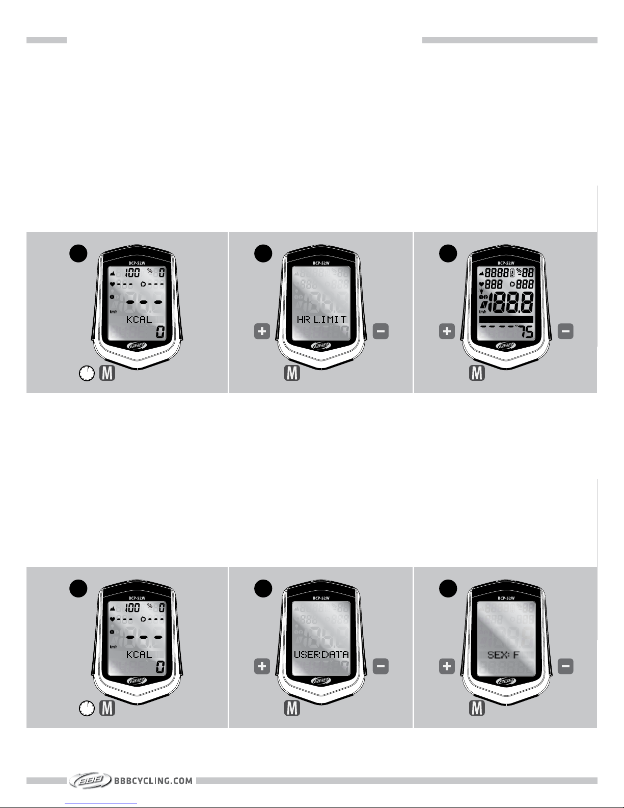
SECTION 4D : ADVANCED SETTINGS : ADVANCED HEART RATE SETTINGS
The user’s Heart Rate HI LIMIT and LO LIMIT are set during the First-Time Set-Up, page 11.
1. To change these limits start with the HEART RATE menu (KCAL shown in display). Press M
button for 3 seconds.
2. If the display shows USER DATA, change into HR LIMIT by pressing + or - . To select press M.
3. Set the heart rate values as described on page 11.
HEART RATE LIMIT SET-UP
The User Data (Sex, Weight) are set during the First-Time Set-Up, page 12.
1. To change these data start with the HEART RATE menu (KCAL shown in display). Press M
button for 3 seconds.
2. If the display shows HR LIMIT, change into USER DATA by pressing + or - . To select press M.
3. Set the SEX and WEIGHT values as described on page 12.
USER DATA SET-UP
1
2
3s
1
2
3s
3
3
25
Page 27
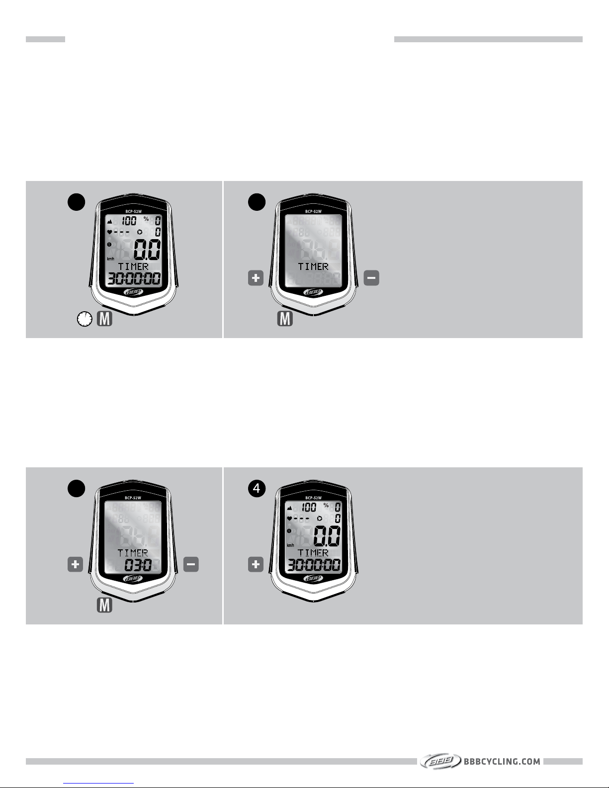
SECTION 4E : ADVANCED SETTINGS : ADVANCED CADENCE SETTINGS
1. To set up the distance countdown function start with the CADENCE menu (TIMER or DIST.
CD shown in display). Press M button for 3 seconds.
2. To choose between DISTANCE COUNTDOWN or TIME COUNTDOWN , press + or -. To select
press M.
DISTANCE OR COUNTDOWN TIMER SET-UP
1
2
3s
26
3. To select the first digit, press + or -. To select press M. Repeat these steps to select the
other digits.
4. To start the DISTANCE COUNTDOWN or TIME COUNTDOWN, press +.
3
Page 28
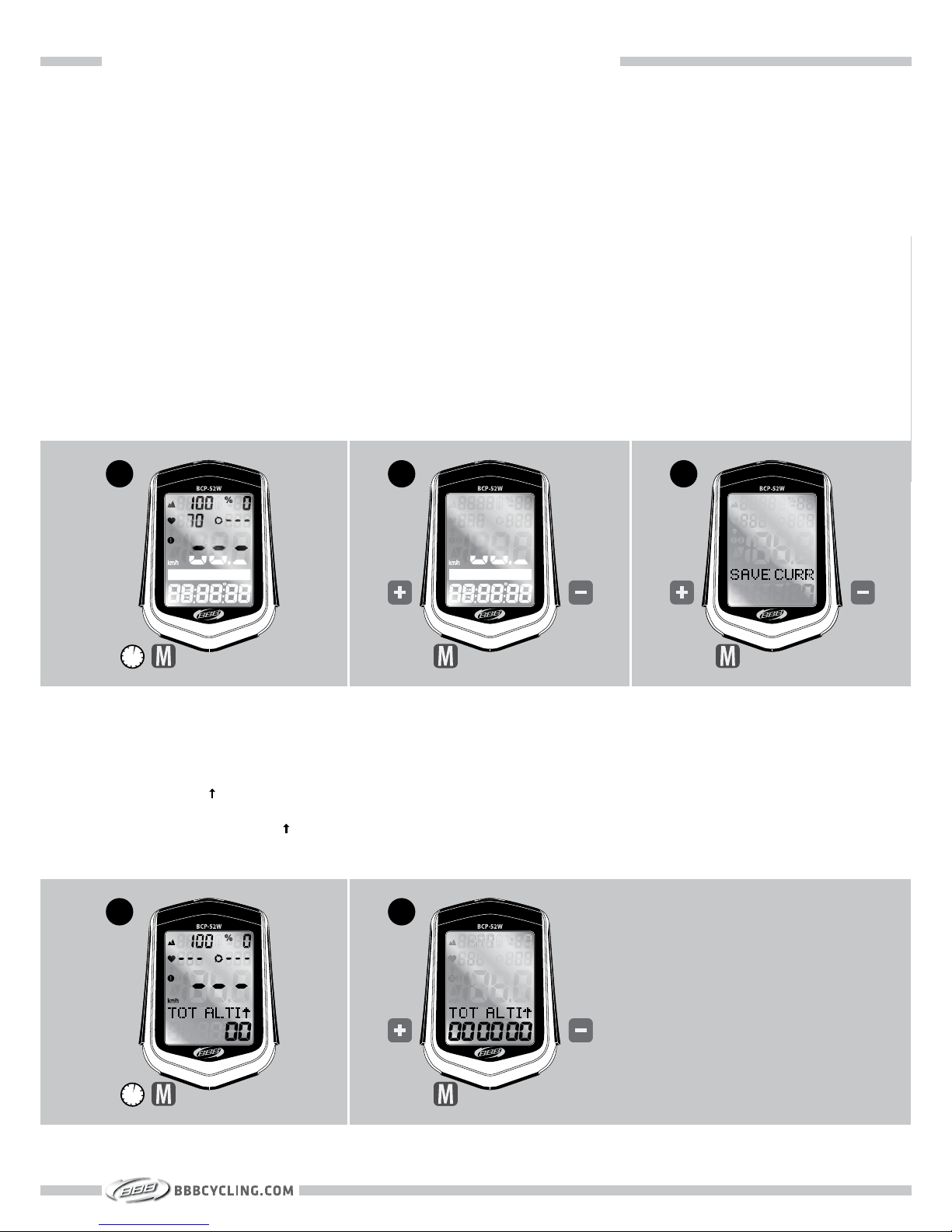
SECTION 4F : ADVANCED SETTINGS : ADVANCED ALTITUDE SETTINGS
Page 17 shows how to set the home altitude. The home altitude can be described as preset
start altitude.
It is also possible to change the start altitude without changing the home preset. This can be
useful when you want to change the start altitude without losing the saved home altitude. For
example when you ride only one day on an altitude that is different from home or when your
ride starts at a different altitude every day.
1. Start with the ALTITUDE menu (ALTI GAIN shown in display). Press M button for 3 seconds.
2. To set the ALTITUDE, press + or -. To select press M . Repeat to set the other digits.
3. To change between SAVE HOME and SAVE CURR press + or -. Select SAVE CURR and press
M. Now the altitude in the display is changed to the altitude you entered. The preset home
altitude is not changed.
HOME ALTITUDE OR CURRENT ALTITUDE (BCP-52WA / BCP-52WAH ONLY)
1
2
3s
3
1. To enter the total gained altitude data manually, start with the ALTITUDE menu
( TOT ALTI shown in display). Press M button for 3 seconds.
2. To set the TOT ALTI press + or - . To select press M. Repeat these steps to set the other
digits.
TOTAL ALTITUDE GAIN SET-UP (BCP-52WA / BCP-52WAH ONLY)
1
2
3s
27
Page 29

SECTION 4F : ADVANCED SETTINGS : TEMPERATURE SETTINGS AND BACKLIGHT
1. To change between °C or °F start with the ALTITUDE menu (TEMP shown in display). Press
M button for 3 seconds.
SETTING °C or °F (BCP-52WA / BCP-52WAH ONLY)
1
3s
28
1. The backlight can be activated in any function by pressing the – button. The backlight will
automatically go off after 3 seconds.
2. To activate the automatic backlight function press – button for 3 seconds in any function.
When the automatic backlight function is activated the backlight symbol is visible in the
LCD display. When automatic backlight is activated the backlight will switch on for 3 seconds when a button is pressed.
3. To switch off the automatic backlight function press – button for 3 seconds in any function.
The backlight symbol will disappear from the LCD display
BACKLIGHT
1
2
3s
3
3s
Page 30

SECTION 5 : ADDITIONAL INFORMATION
SECTION 5
ADDITIONAL INFORMATION
29
Page 31
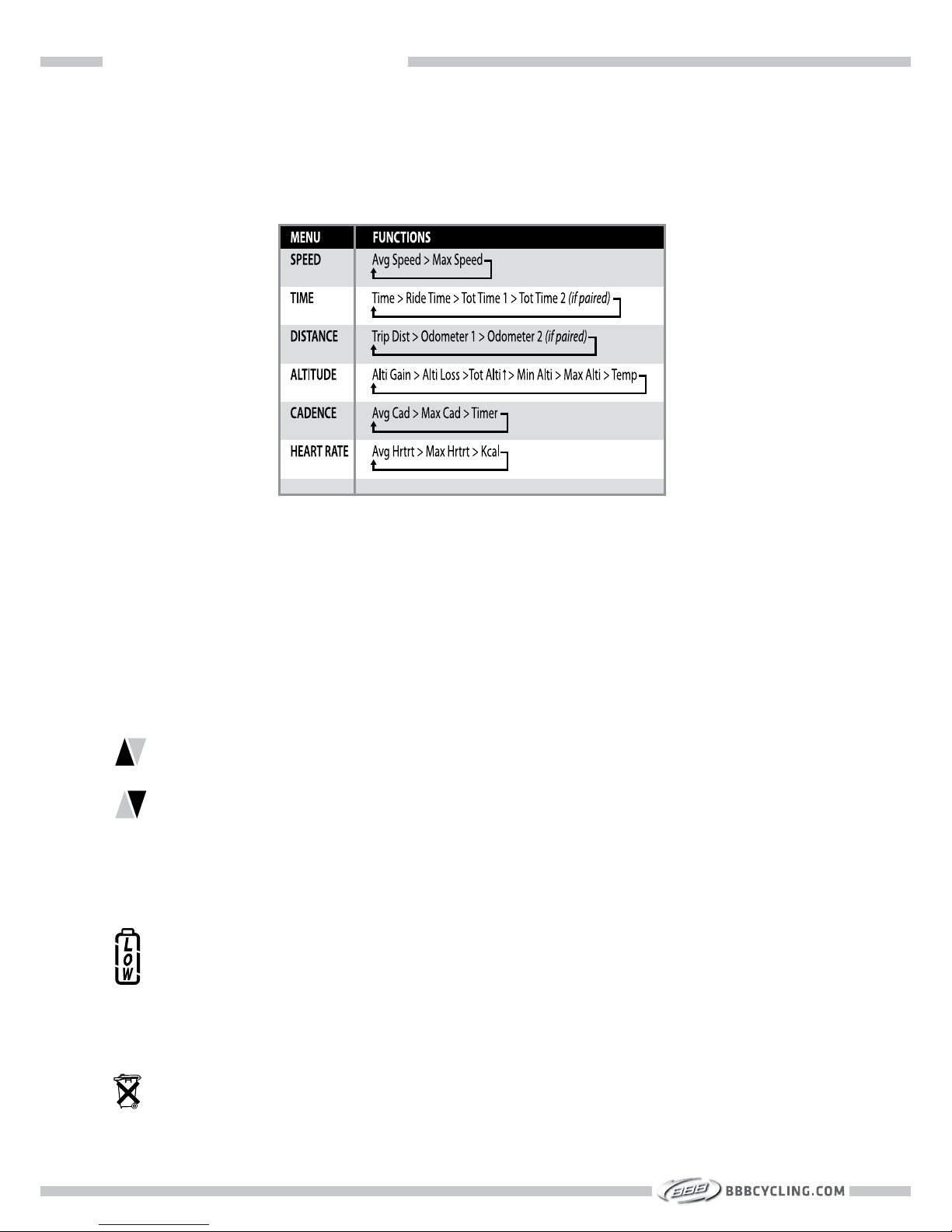
SECTION 5 : ADDITIONAL INFORMATION
To change between the different menu’s press M .
To check different functions within a menu press F.
A. MENU STRUCTURE
SPEED PACER
The SPEED PACER compares your current speed with your average speed.
= Current speed is above average speed.
= Current speed is below average speed.
LOW BATTERY INDICATOR
When the LOW BATTERY indicator appears on the display the battery in the main unit
needs to be changed. Before changing the battery, write down your ODO and TOTAL
TIME data.
The computer will automatically reset when the battery is removed. After installing a
new battery you can set your ODO and TOTAL TIME data.
Batteries should be disposed in compliance with local regulations.
B. DISPLAY ELEMENTS
30
Page 32
SECTION 5 : ADDITIONAL INFORMATION
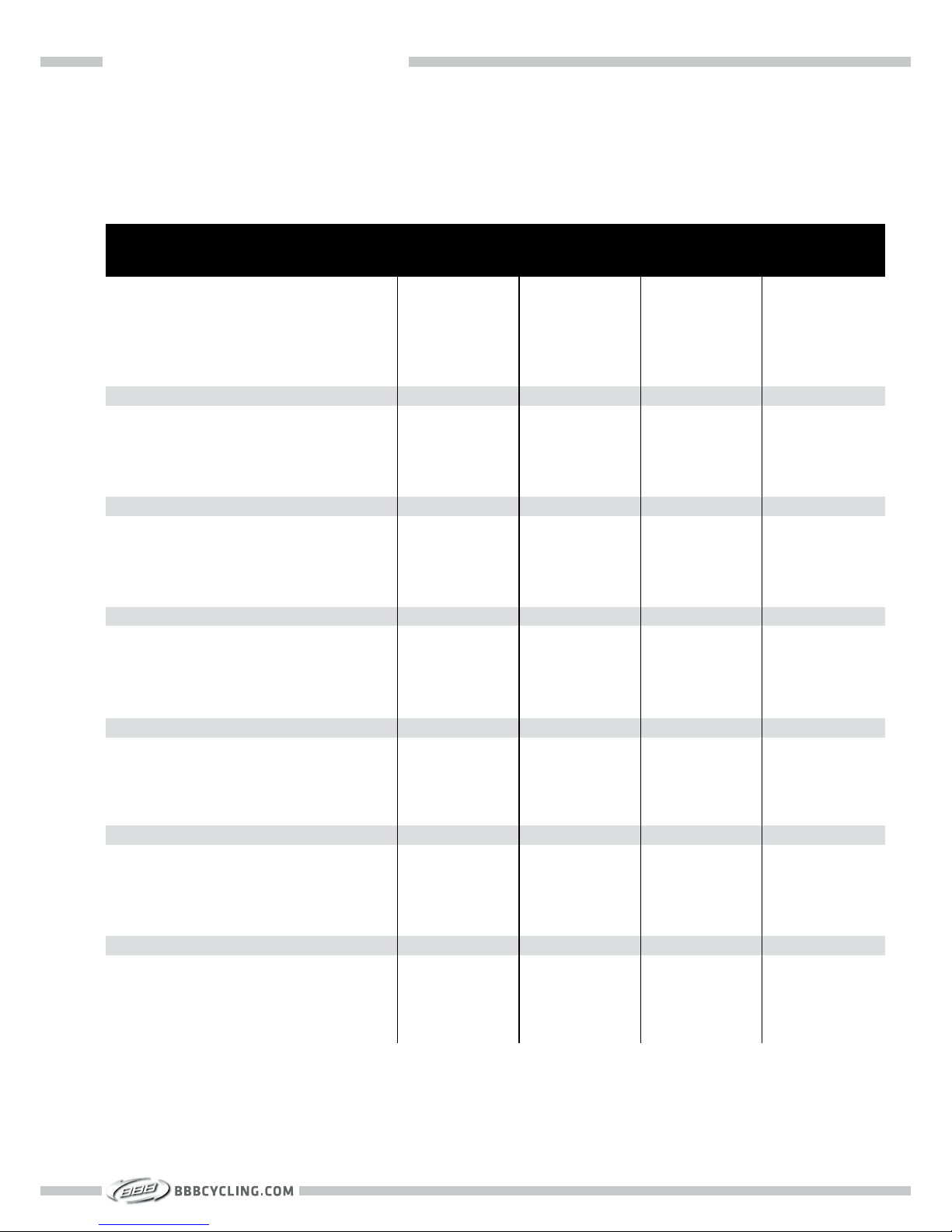
C. FUNCTIONS OVERVIEW
Current speed
Average speed
Maximum speed
Riding time
Trip distance
Odometer 1
Odometer 2
Total odometer (1+2)
Clock (12 / 24h)
Low battery indicator
Auto start / stop
Speed pacer
Backlight
Total riding time 1
Total riding time 2
2nd wheel size
Auto sleep
Altitude
Home altitude storage
Altitude gain / loss
Maximum altitute
Minimum altitute
Percent grade
Total altitude gain (1+2)
Temperature (°C / °F)
Heart rate
Maximum heart rate
Average heart rate
Calories used
Upper / lower limit
Cadence transmitter set (BCP-56)
Heart rate transmitter set (BCP-57)
BCP-52WAH
(30 functions)
O
O
O
O
O
O
O
O
O
O
O
O
O
O
O
O
O
O
O
O
O
O
O
O
O
O
O
O
O
O
Optional
Included
BCP-52WA
(25 functions)
O
O
O
O
O
O
O
O
O
O
O
O
O
O
O
O
O
O
O
O
O
O
O
O
O
-
-
-
-
-
Optional
Optional
BCP-51WH
(22 functions)
O
O
O
O
O
O
O
O
O
O
O
O
O
O
O
O
O
-
-
-
-
-
-
-
-
O
O
O
O
O
Optional
Included
BCP-51W
(17 functions)
O
O
O
O
O
O
O
O
O
O
O
O
O
O
O
O
O
-
-
-
-
-
-
-
-
-
-
-
-
-
Optional
Optional
31
Page 33
SECTION 5 : ADDITIONAL INFORMATION
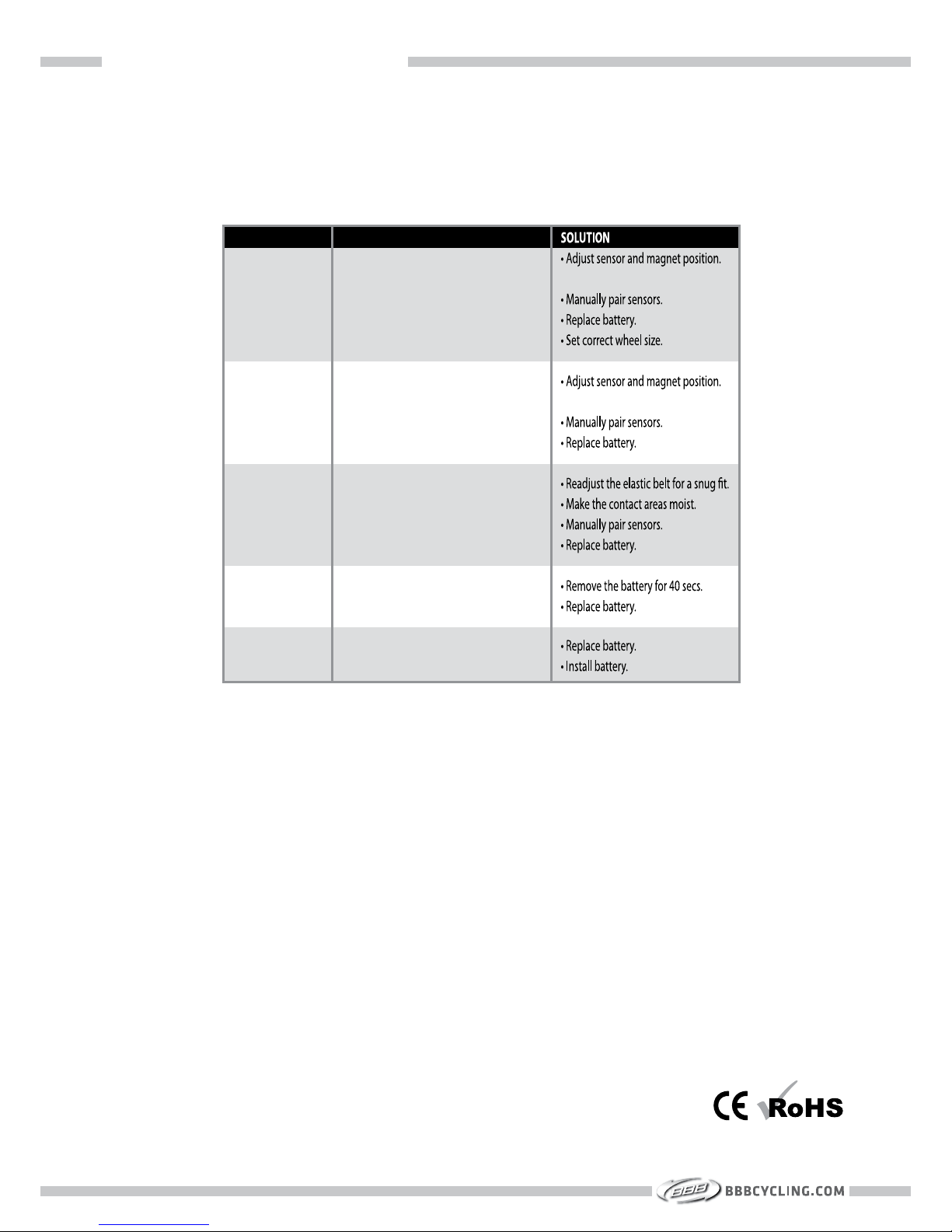
Check the following before taking the BBB DigiBoard in for repairs.
D. TROUBLESHOOTING
PROBLEM
No speed or
incorrect speed.
No cadence or
incorrect cadence.
No heart rate or
incorrect heart rate.
Transmitter will
not pair.
Blank screen.
POSSIBLE CAUSES
• Magnet is not aligned or distance between
sensor and magnet is too big.
• Transmitter is not paired.
• Battery power is low.
• Wheel size is incorrect.
• Magnet is not aligned or distance between
sensor and magnet is too big.
• Transmitter is not paired.
• Battery power is low.
• Elastic belt is too loose.
• Contact areas are not moist.
• Transmitter is not paired.
• Battery power is low.
• Transmitter is not active.
• Battery power is low.
• Battery is empty.
• No battery installed.
Transmission platform: ANT+
Operation temperature: -10 °C to +60 °C / 14 °F to 140 °F.
Storage temperature: -20 °C to +70 °C / -4 °F to 158 °F
Main unit battery power: 3V Lithium battery: 1x (CR2032)
Dimensions and weight of main unit: 63 x 46 x 19.5mm / 33g
E. TECHNICAL SPECIFICATIONS
Batteries should be disposed in compliance with local regulations.
32
Page 34
Augusta Benelux BV
Rooseveltstraat 46
2321 BM
Leiden, The Netherlands
Tel (31)71 - 57 91 580
Fax (31)71 - 53 23 201
Email: [email protected]
BBBCYCLING.COM
 Loading...