

Page 1
Page 2
All rights reserved by DigiBird
®
1
Page 3

ideo & Image Processing
Research & Development, Manufacturing and Sales
V
NO TICES…………………………………………………………………………………………………………………4
I. Introduction……………………………………………………………………………………………………………6
1.1 About This Guide………………………………………………………………………………………………………………6
1.2 About the DB-RC4 v2 Video Wall Controller…………………………………………………………………………………6
1.3 Key Features of the DB-RC4 v2 Video Wall Controller……………………………………………………………………6
1.4 Video Wall Layout Examples…………………………………………………………………………………………………7
II. The DB-RC4 v2 Hardware……………………………………………………………………………………………8
2.1 Unpacking and inspection……………………………………………………………………………………………………8
2.2 Hardware Overview……………………………………………………………………………………………………………8
2.2.1 Technical Specification……………………………………………………………………………………………………9
2.2.2 Front Panel…………………………………………………………………………………………………………………9
2.2.3 Rear Panel………………………………………………………………………………………………………
2.2.4 Side View………………………………………………………………………………………………………………10
2.2.5 Optional Hardware (sold separately)……………………………………………………………………………………10
2.3 DB-RC4 v2 Hardware Installation………………………………………………………………………………………………11
2.3.1 Factory Default Settings…………………………………………………………………………………………………11
2.3.2 Installation Steps…………………………………………………………………………………………………………11
2.4 Connection Diagram…………………………………………………………………………………………………………12
…………9
III. About the DB-RC4 v2 Control and Design Software…………………………………………………………12
3.1 Computer System Requirements……………………………………………………………………………………………13
3.2 Software and Driver: Installing and Uninstalling…………………………………………………………………………13
3.2.1 Installing the Driver………………………………………………………………………………………………………13
3.2.2 Installing the Software……………………………………………………………………………………………
3.2.3 Uninstalling the Software………………………………………………………………………………………………16
………14
IV. Running the Software……………………………………………………………………………………………18
V. Software Operation………………………………………………………………………………………………18
5.1 Software Overview……………………………………………………………………………………………………………19
5.2 Mounting Wall Size Setting…………………………………………………………………………………………………20
5.3 Input Resolution Settings……………………………………………………………………………………………………22
5.4 Monitor Settings………………………………………………………………………………………………………………24
5.4.1 Monitor Selection………………………………………………………………………………………………………24
5.4.2 Adding New Monitors…………………………………………………………………………………………………26
5.4.3 Delete a Custom Monitor………………………………………………………………………………………………27
5.5 Physical Layout Design and Settings………………………………………………………………………………………28
5.5.1 Toolbar for Physical Layout Settings…………………………………………………………………………………30
5.5.2 Centered Icon……………………………………………………………………………………………………………30
5.5.3 Rotate Icon………………………………………………………………………………………………………………30
5.5.4 Sync to Capture Regions Icon…………………………………………………………………………………………31
5.6 Capture Regions Settings……………………………………………………………………………………………………33
5.6.1 Moving and Resizing the Capture Regions……………………………………………………………………………33
5.6.2 Zooming in or out the Capture Regions Window……………………………………………………………………33
All rights reserved by DigiBird
2
®
Page 4

5.6.3 Context Menu of the Capture Regions………………………………………………………………………………34
5.6.4 Layering the Capture Regions…………………………………………………………………………………………35
5.6.5 Flip Horizontally or Vertically……………………………………………………………………………………………36
5.6.6 Capture Regions Properties……………………………………………………………………………………………37
5.6.7 How to Calculate the Pixel Size and Position of a Capture Region………………………………………………37
5.7 Adding a Device (DB-RC4 v2)…………………………………………………………………………………………………39
5.8 Apply……………………………………………………………………………………………………………………………41
5.9 Refresh…………………………………………………………………………………………………………………………41
5.10 Conguration Template Management……………………………………………………………………………………42
5.11 EDID Management…………………………………………………………………………………………………………42
5.11.1 Read EDID……………………………………………………………………………………………………………42
5.11.2 Write EDID to Input……………………………………………………………………………………………………43
5.11.3 Open EDID File…………………………………………………………………………………………………………43
5.12 Test……………………………………………………………………………………………………………………………44
5.13 Language……………………………………………………………………………………………………………………44
5.14 About…………………………………………………………………………………………………………………………44
All rights reserved by DigiBird
®
3
Page 5

ideo & Image Processing
Research & Development, Manufacturing and Sales
V
NOTICES
Important Notices
Thank you for purchasing this DigiBird ® product. To prevent damage to your DigiBird product or injury to personnel
when operating this equipment, please read the following safety precautions and user guide prior to operation.
This manual includes detailed instructions for software operation. Please refer to this manual or contact DigiBird if
you have any questions. DigiBird reserves the right to make changes in the hardware, software, packaging, and any
accompanying documentation without prior written notice.
Copyright © DigiBird®. All rights reserved.
The copyrights of the software indicated in this manual are reserved by DigiBird. They are protected by patent and
copyright laws.
Without written notice or authorization, any entity or person shall not copy, quote, duplicate, print or translate
this manual and shall not share or publish it through any unauthorized manner. Without DigiBird or its licensor’s
authorization, any entity or person shall not copy, distribute, modify, extract, decompile, disassemble, decode, reverse
engineer, rent, transfer or re-license to another entity or person, except for the conditions stipulated by Law or
government requests.
Trademarks
All trademarks noted in this guide are the properties of their respective owners.
The DigiBird logo, name and other DigiBird trademark rights are reserved.
Limitations
This manual is based on “the current condition”, except for the stipulation of law. DigiBird does not provide any
ostensive or implicit guarantee, including but not limited to the guarantees of merchantability or specific purpose.
Under the scope of law, DigiBird assumes no responsibility for any inaccuracies that may be contained in this manual.
In no event will DigiBird be liable for direct, indirect, special, incidental, or consequential damages resulting from any
defect or omission in this manual, even if advised of the possibility of such damages. Nor shall DigiBird be liable for any
compensation for any income, information, business reputation or any anticipated saving cost for the users.
Third-party Software
Regarding any third-party software or applications referred to in this manual that DigiBird does not own or hold the
licensed copyright to, DigiBird cannot provide any guarantee for the operation of third-party software or applications
and does not provide any technical support for them. In no event will DigiBird be liable or take responsibility for the
handling or usage of these third-party software or applications.
The service of third-party software or applications may fail or crash. In no event will DigiBird be liable for the usability
of those software or applications. In no case will DigiBird be liable for the validity, quality or other services of software
or applications modied by the user.
All rights reserved by DigiBird
4
®
Page 6
Safety Precautions
To prevent damage to your DigiBird product or injury to personnel operating the equipment, please read the safety
precautions prior to operation.
1) Make sure your PC conguration meets the minimum requirements indicated in this manual.
2) Make sure the operating system is compatible with the requirements indicated in this manual.
3) Make sure your operating system is safe, stable and free of viruses.
4) Close other running applications when installing this software.
Notications
The following notications are used in this guide:
ATTENTION: Attention indicates a situation that may damage or destroy the product or associated equipment.
NOTE: A note draws attention to important information.
I. Introduction
All rights reserved by DigiBird
®
5
Page 7

ideo & Image Processing
Research & Development, Manufacturing and Sales
V
I. Introduction
Thank you for choosing the DigiBird DB-RC4 v2. Before you begin conguring your DB-RC4 v2 for the rst time, please
read completely through the document to become familiar with its features. This section gives an overview of the user
guide and features of the DB-RC4 v2 Video Wall Controller and Control & Design Software. Topics include:
About this Guide
About the DB-RC4 v2
Key Features of the DB-RC4 v2
Video Wall Layout Examples
1.1 About This Guide
This guide provides detailed information about the DB-RC4 v2 Hardware and DB-RC4 v2 Control and Design Software,
including software installation and conguration. This guide also describes how the software controls the DB-RC4 v2
Video Wall Controller. The features and functionality described in this guide are based on version 2.0 of the DB-RC4 v2
Control and Design Software with DB-RC4 v2 rmware version 2.0.0.0 and later. For the latest details on rmware and
software, and for additional updates, visit our website at www.digibirdtech.com.
1.2 About the DB-RC4 v2 Video Wall Controller
The DigiBird DB-RC4 v2 Video Wall Controller is the simplest and most cost-effective solution to build an eye-catching
and creative video wall. It is an ideal video wall solution for retail stores, shopping malls, restaurants, sport bars, hotel
lobbies, trade shows and entertainment venues.
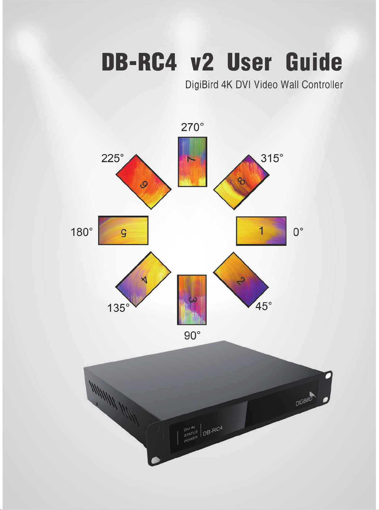
The DB-RC4 v2 breaks the limitations of the traditional video wall alignment. Unlike traditional video walls, the DB-RC4
v2’s displays and each of its outputs can be independently ipped or rotated 45°, 90°, 135°, 180°, 225°, 270°or 315°. It
also supports the alignment of varying resolutions and display sizes to build a distinctive, asymmetrical video wall. The
DB-RC4 v2 is a compact video wall controller/processor that features one single or dual-link DVI input that provides
stunning 4K × 4K input capability and can exibly route the input to four output displays.
1.3 Key Features of the DB-RC4 v2 Video Wall Controller
Controls up to four displays in a wall conguration.
•
Cascades multiple units to create walls with more than four displays.
•
Bezel compensation for input image across screens.
•
Supports image rotation and mirroring. Each output can be independently rotated 45°, 90°, 135°, 180°, 225°,
•
270°or 315° and ipped horizontally or vertically.
The displays aligned in the video wall can be of different sizes and of native resolution.
•
Supports automatic frame lock. When the timings of the four monitors are the same, genlock will be activated.
•
The genlock feature guarantees uid motion video and minimizes latency to a single frame.
Accepts Single-Link or Dual-Link DVI and HDMI input signal formats. (A DVI-to-HDMI adapter is required.)
•
Ultra high input resolutions up to 4K x 4K (4088 pixels x 4088 lines).
•
Supports connections to four DVI-I (VGA, DVI) displays, and all VESA resolutions (up to 1920×1200@60Hz) are
•
supported. The four different output resolutions can be supported.
The input source can be cropped at the user’s discretion and copied to an output monitor. The smallest
•
cropping area is one pixel.
Supports exible EDID management.
•
Automatic input and output signal detection.
•
Congure using windows-based software installed on a PC connected via a USB link.
•
Durable, stainless steel chassis.
•
Windows
•
All rights reserved by DigiBird
6
®
XP, Windows® 7 (32, 64-bit), Windows® 8 (32, 64-bit), Windows® 10 (32, 64-bit) compatible.
®
Page 8
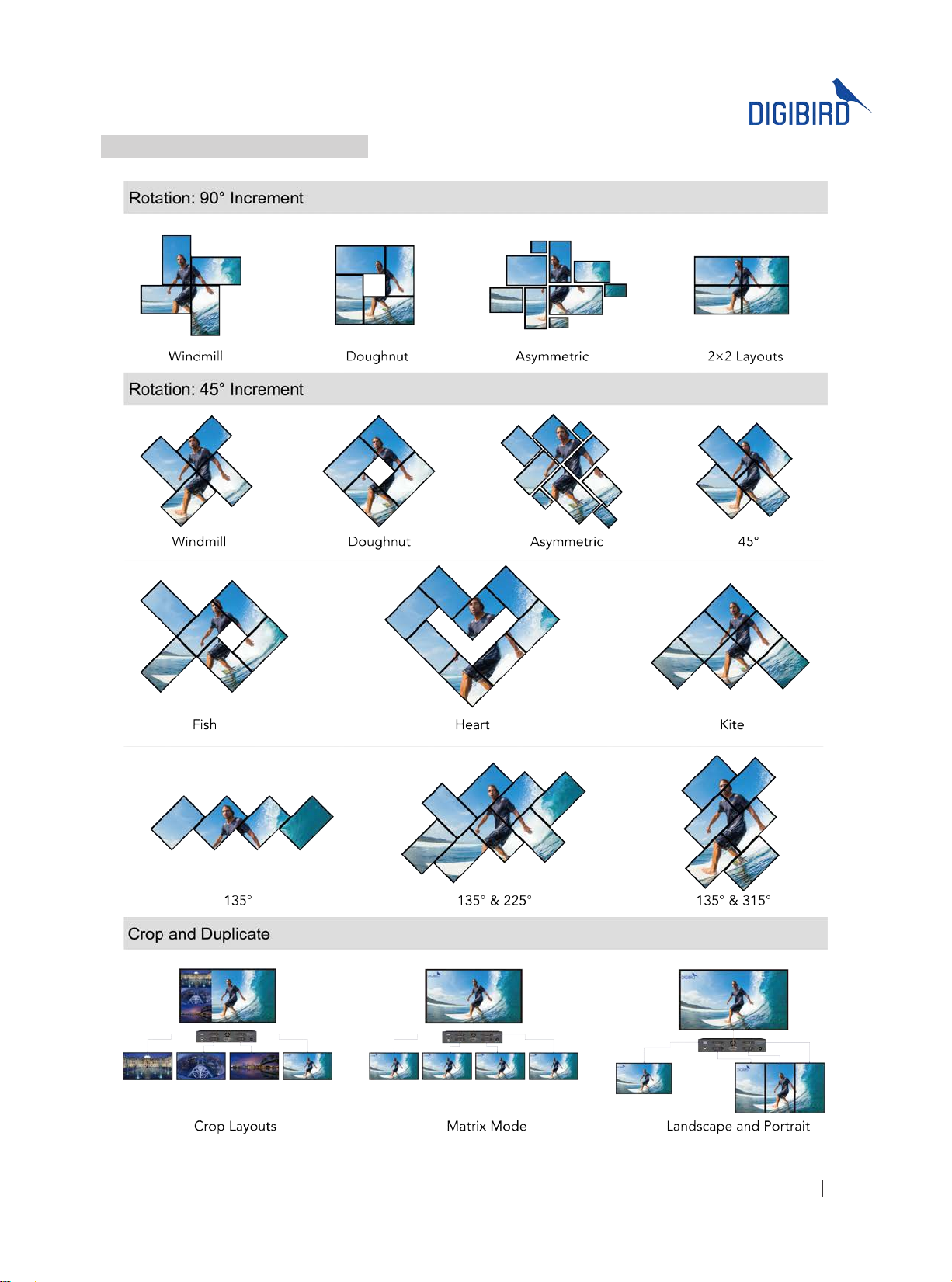
1.4 Video Wall Layout Examples
Figure 1.4 Video Wall Layout Examples
All rights reserved by DigiBird
®
7
Page 9

ideo & Image Processing
Research & Development, Manufacturing and Sales
V
II. The DB-RC4 v2 Hardware
2.1 Unpacking and inspection
Your packing box should contain the following items:
Items Quantity
DigiBird DB-RC4 v2 enclosure
DB-RC4 v2 AC/DC Switching Power Adapter
Standard Computer Power Cord, 10A, 18AWG (NEMA 5-15P to IEC-320-C13), 6-ft. (American
Standard) or 1× CEE7/7 Male Plug to 2 Way IEC 60320 C13 Connector 6 Feet 10a/250v power cord
(European Standard)
1x
1x
1x
USB 2.0 Cable Type A Male to Type B Male 5 feet, Black
DigiBird CD containing Software Installation File and User Guide (PDF version)
Warranty Card
User guide and Software are also available on
www.digibirdtech.com.
1x
1x
1x
Before connecting any inputs or outputs, it is advised to power on the unit. Should you encounter any
problems powering on the unit, immediately contact your local distributor or dealer.
The DB-RC4 v2 enclosure will arrive boxed with internal foam for protection during shipping.
You are encouraged to retain the box and all packing material so the unit can be returned in the
unlikely event that repairs should ever become necessary.
2.2 Hardware Overview
2.2.1 Technical Specication
(1) Single-Link or Dual-Link DVI-I female for input
Connectors
Indicators (1) Power LED, (1) Input LED, (1) Status LED
(4) DVI-I female for output
(1) power connector female
(1) USB-B female
Outputs 4 x Single-Link DVI or analog RGB outputs, up to 1920×1200@60Hz
Input Resolution Up to 4K×4K
Input Clock Rate 330MHz
Input Bandwidth 9.9Gbps
Arbitrary Upscaling Unlimited upscaling for original cropped area
Operating Humidity 90% non-condensing
Operating Temperature 32º to 104ºF (0º to 40ºC)
Input: 100-240 VAC, 1.4 Amps
Power
All rights reserved by DigiBird
8
Output: 12 VDC, 5 Amps
Consumption: 40 Watts
®
Page 10
Dimensions
1.75”H x 8.86”W x 8.66”D (44.5mm x 225mm x 220mm) without rack mount ears
1.75”H x 10.24”W x 8.66”D (44.5mm x 260mm x 220mm) with rack mount ears
Package Dimensions 3.74”H x 17.72”W x 12.20”D (95mm x 450mm x 310mm)
Net Weight 1.26 Kg or 2.78 lbs
Gross Weight 2.87 Kg or 6.33 lbs
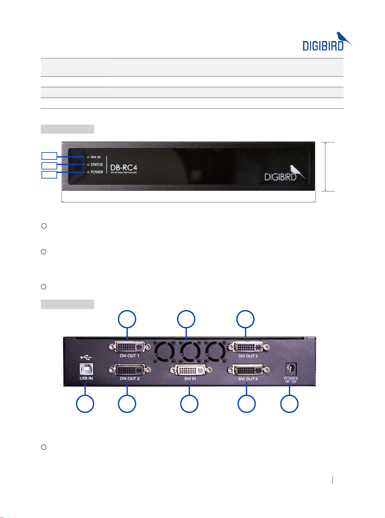
2.2.2 Front Panel
1
2
3
Height 1.75"(44.5mm)
Width 8.86"(225mm)
Figure 2.2.2 Front Panel
1
DVI IN indicator LED: When the DVI IN LED lights orange, it indicates a valid input source is connected to the input
interface of the DB-RC4 v2.
2
Status indicator LED: Solid-state lighting indicates the DB-RC4 v2 is running properly. When the LED is blinking, it
means the detected input resolution doesn’t match the default or congured input resolution. The user should follow
the instructions and modify the conguration using the software.
3
Power indicator LED: This LED lights orange when the DB-RC4 v2 is powered on.
2.2.3 Rear Panel
252
1 2 3 2 4
Figure 2.2.3 Rear Panel
1
USB Type B Port: This USB Type B port is compatible with USB 1.0 and 2.0. The USB port is used to connect the
DB-RC4 v2 to your control PC. A USB Type A to Type B cable is supplied with the DB-RC4 v2. The DB-RC4 v2 can be
controlled via the USB port while using the windows-based software.
All rights reserved by DigiBird
®
9
Page 11
ideo & Image Processing
Research & Development, Manufacturing and Sales
V
2
DVI-I Output Port # 1 to # 4: The four black DVI-I Output ports are used to connect the DB-RC4 v2 to the output
monitors or displays. The DVI-I outputs support both DVI and analog RGB (VGA) signals.
3
DVI IN Port: The DVI IN port (white) is applied to connect the input source. The DB-RC4 v2 supports Single-Link
DVI-D, Dual –Link DVI-D and HDMI (not HDCP compliant) signals. When connecting an HDMI source, like a PC or
laptop with an HDMI graphics card, an HDMI to DVI adapter is needed. Use a DVI-I connector as it is compatible with
most DVI cables.
4
Power Socket: The power socket is used to connect the DB-RC4 v2 power adapter. The parameters of the AC-DC
switching power adapter is shown below:
Input: 100-240 VAC, 50/60hz, 1.4A Output: 12V DC, 5.0A, 60W Max.
5
Ventilation Hole: System fan and ventilation hole. Do not obstruct the ventilation hole as it may cause the DB-RC4
v2 to overheat.
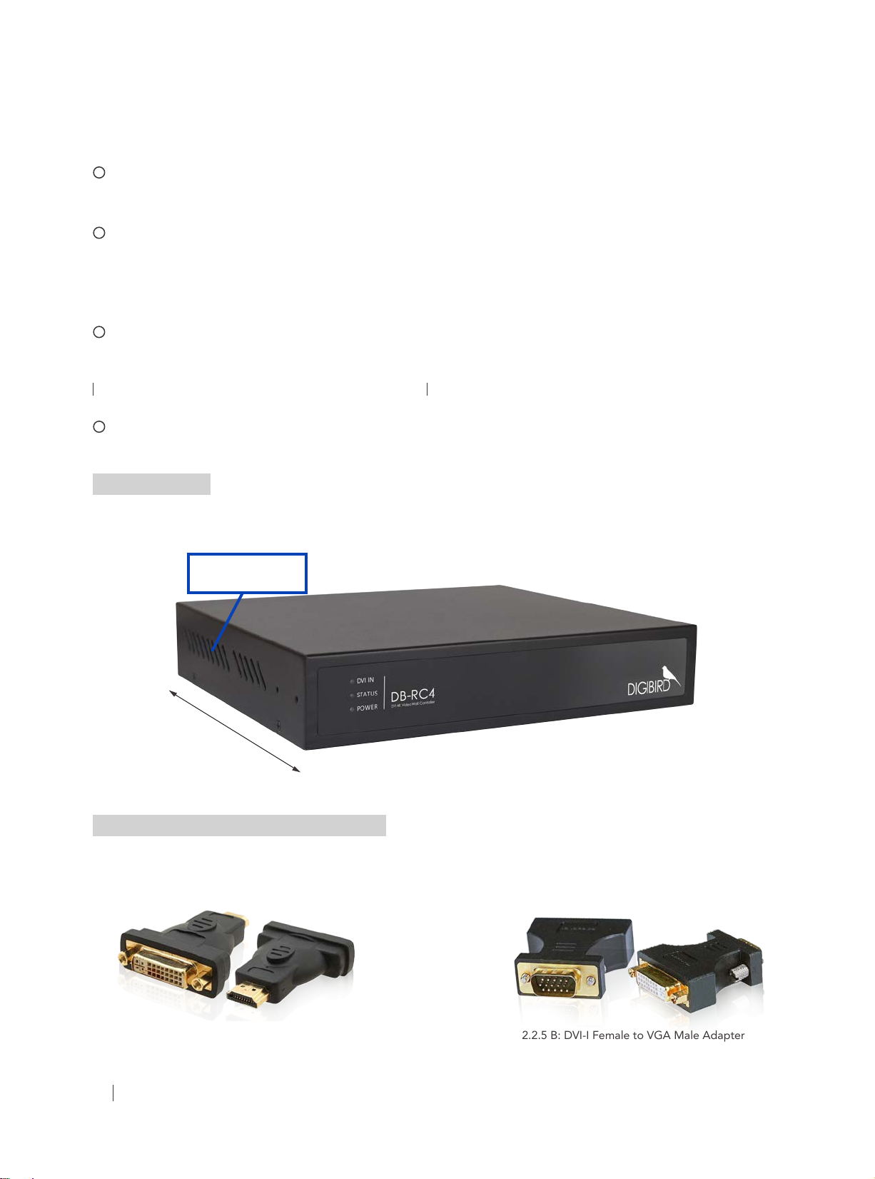
2.2.4 Side View
The following gures show both sides of the DB-RC4 v2 ventilation grilles. Do not obstruct the ventilation grilles under
any circumstances.
Ventilation Grilles
Depth 8.66"(220mm)
Figure 2.2.4 Side View
2.2.5 Optional Hardware (sold separately)
Depending on your needs, you may also require the following hardware:
A. HDMI to DVI adapter for DB-RC4 v2 input B. DVI to VGA adapter for DB-RC4 v2 outputs
Figure 2.2.5 A: HDMI Male to DVI-I Dual Link Female Adapter Figure 2.2.5 B: DVI-I Female to VGA Male Adapter
All rights reserved by DigiBird
10
®
Page 12
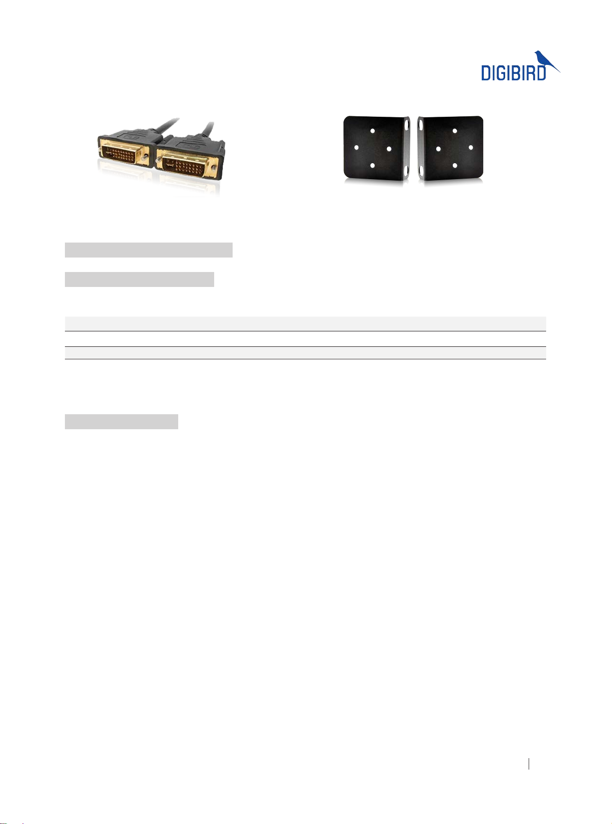
C. High Quality DVI cables (male-to-male) D. Rack Ears
Figure 2.2.5 C: DVI-I Dual-Link Digital/Analog Cable Figure 2.2.5 D: Rack Ears
2.3 DB-RC4 v2 Hardware Installation
2.3.1 Factory Default Settings
The factory default settings are shown here:
Input EDID Preferred Mode 1920 x 1080 x 60Hz (SMPTE timings)
Output monitor resolution 1920 x 1080 x 60Hz (SMPTE)
Layout Mode Duplicate Mode and No Rotation
The default settings can be modied with the DB-RC4 v2 Video Wall Control and Design Software (RCS). Refer to the
software section in the DB-RC4 v2 user guide that came with your product.
2.3.2 Installation Steps
1) Disconnect all equipment from power sources.
2) (Optional) Mount the DB-RC4 v2 to a rack or other desired place using the optional rack mount ears.
3) Monitors/Displays Installation: Install the monitors or displays at the desired place. A video wall mounting
system could be needed for your specic installation needs. The monitors may be rotated from their traditional
landscape-style placement according to the user’s requirement. It is strongly recommended to employ a
clockwise rotation.
4) Input Connection: Connect the DVI IN port (white, single-link or dual-link DVI) of the rear panel to an input
source, like a graphic workstation, PC or laptop. The DVI input is not compatible with HDCP which means you
cannot use a Blu-ray DVD as an input source.
5) Output Connection: Connect the DVI-I Dual-Link Digital/Analog Cables to the DVI outputs of the rear panel
starting from number 1 to number 4.
6) Control Connection: Connect the USB to the port of the rear panel and to the controlling PC’s port using the
USB Type A to Type B cable.
7) Power Connections:
Connect the DC output connector of the DB-RC4 v2 AC/DC power adapter to the power socket at the rear
panel of the DB-RC4 v2. See Figure 2.3.2 DB-RC4 v2 Power adaptor.
Connect the power cord to the 3-pole AC inlet of the adapter.
Connect the power cord to a reliable source with a voltage between 100 and 240VAC.
8) Power on all connected devices.
9) Install and set up the DB-RC4 v2 control and design software.
10) Use the software to congure the sources and displays for your creative video wall system.
All rights reserved by DigiBird
®
11
Page 13
ideo & Image Processing
Research & Development, Manufacturing and Sales
V
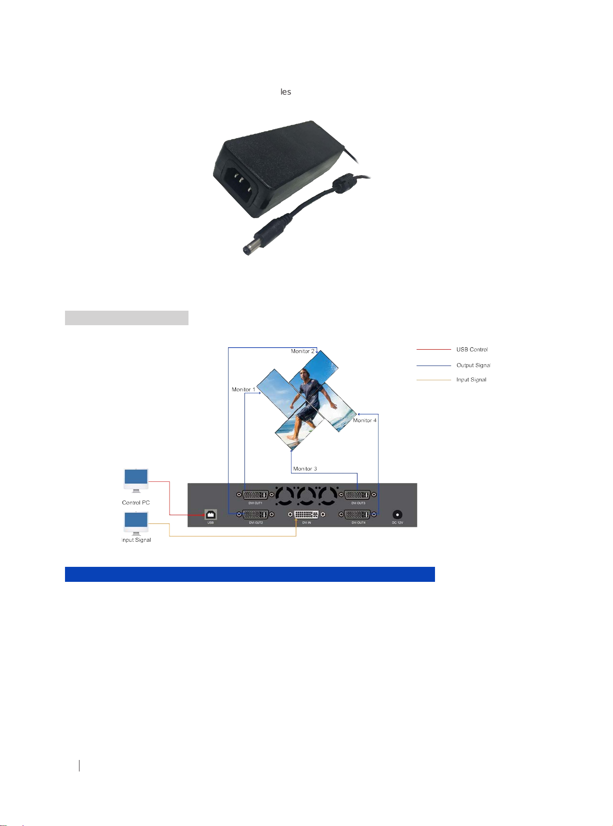
Figure 2.3.2 DB-RC4 v2 Power adaptor
2.4 Connection Diagram
Figure 2.4 Connection Diagram
III. About the DB-RC4 v2 Control and Design Software
The DB-RC4 v2 Control and Design Software is a Microsoft® Windows® -based application used to control the DB-RC4
v2 Video Wall Controller from your computer via a USB cable (compatible with version 1.0 and 2.0).
Some features of the DB-RC4 v2 Control and Design Software include:
User interface is organized into a series of tasks so that you can easily navigate them and set up the video wall.
•
Supports quick setup. Once the dimensions and positions of the monitors are set up, the software is able to
•
automatically calculate the display area.
The monitors in the physical layout and the white frames in the capture regions can be moved by using the up
•
, down↓, left← and right→ arrows on the keyboard.
↑
The DB-RC4 v2 Control and Design Software provides a monitor database, and most well-known
•
manufacturers are already included at launch. It also allows users to add their own monitors manually.
All rights reserved by DigiBird
12
®
Page 14
Monitor information such as screen dimensions (in pixels and millimeters), bezel sizes and refresh rates are all
•
included.
Supports arbitrary cropping of input sources and previewing of cropped regions.
•
A virtual canvas provides a screen layout (physical layout) for the video wall where monitors can be positioned
•
and rotated.
Custom video wall congurations can be saved as templates for future recall.
•
3.1 Computer System Requirements
For the DB-RC4 v2 Control and Design Software to function correctly and reliably, it must be installed on a computer
that meets or exceeds the following criteria:
Minimum Recommended
®
7 32/64-bit, Windows® 8
®
10 32/64-bit
Operating System Windows
®
XP 32-bit and 64-bit versions
Windows
32/64-bit, Windows
CPU
Intel® Pentium® /Celeron® /AMD
Athlon™
®
Core™ i3 or above
Intel
Memory (RAM) 256MB RAM 2GB RAM or above
Hard Disk Free Space 150MB 5G or above
Graphics
1024 x 768, 65K colors
(16-bit)
1024 x 768, 16.7M colors
(32-bit)
CD-ROM DVD-ROM DVD-ROM
Input
Microsoft compatible keyboard and
mouse
Microsoft compatible keyboard and mouse
3.2 Software and Driver: Installing and Uninstalling
This section contains the following topics:
Installing the Driver Installing the Software Uninstalling the Software Running the Software
3.2.1 Installing the Driver
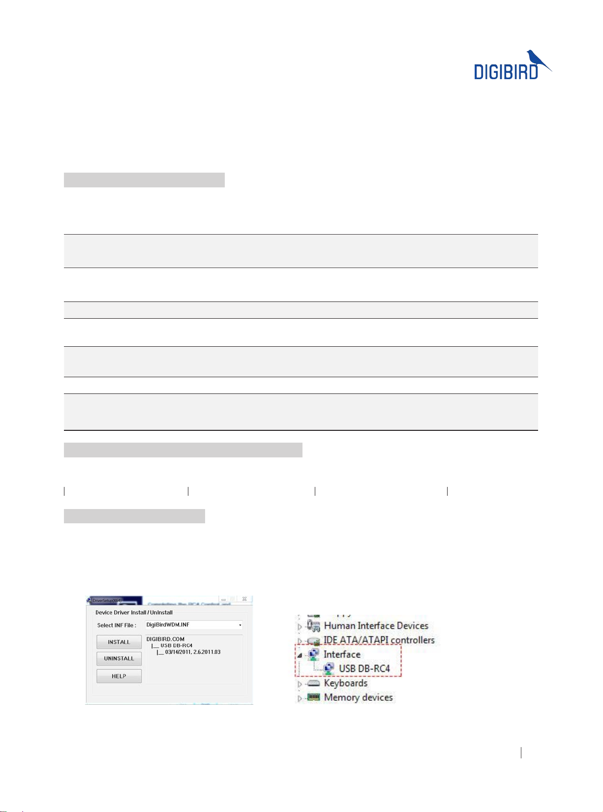
Before installing the DB-RC4 v2 Control and Design Software, the user must install the USB driver.
The USB driver installation steps are shown below:
1. Copy to your computer the le named “RCSCtrl_2.0” from the CD that came with the DB-RC4 v2.
2. Click the “INSTALL” button to install the driver (Figure 3.2.1 A).
Figure 3.2.1 A: Installation of driver
Figure 3.2.1 B: Driver installed
3. When the driver is installed successfully, it will appear in the device manager (Figure 3.2.1 B: Driver installed).
All rights reserved by DigiBird
®
13
Page 15
ideo & Image Processing
Research & Development, Manufacturing and Sales
V
3.2.2 Installing the Software
The Control and Design Software installation file is provided on a CD with your DB-RC4 v2 (it is also available for
download from the DigiBird website at www.digibirdtech.com). Install the program on your computer in the following
way:
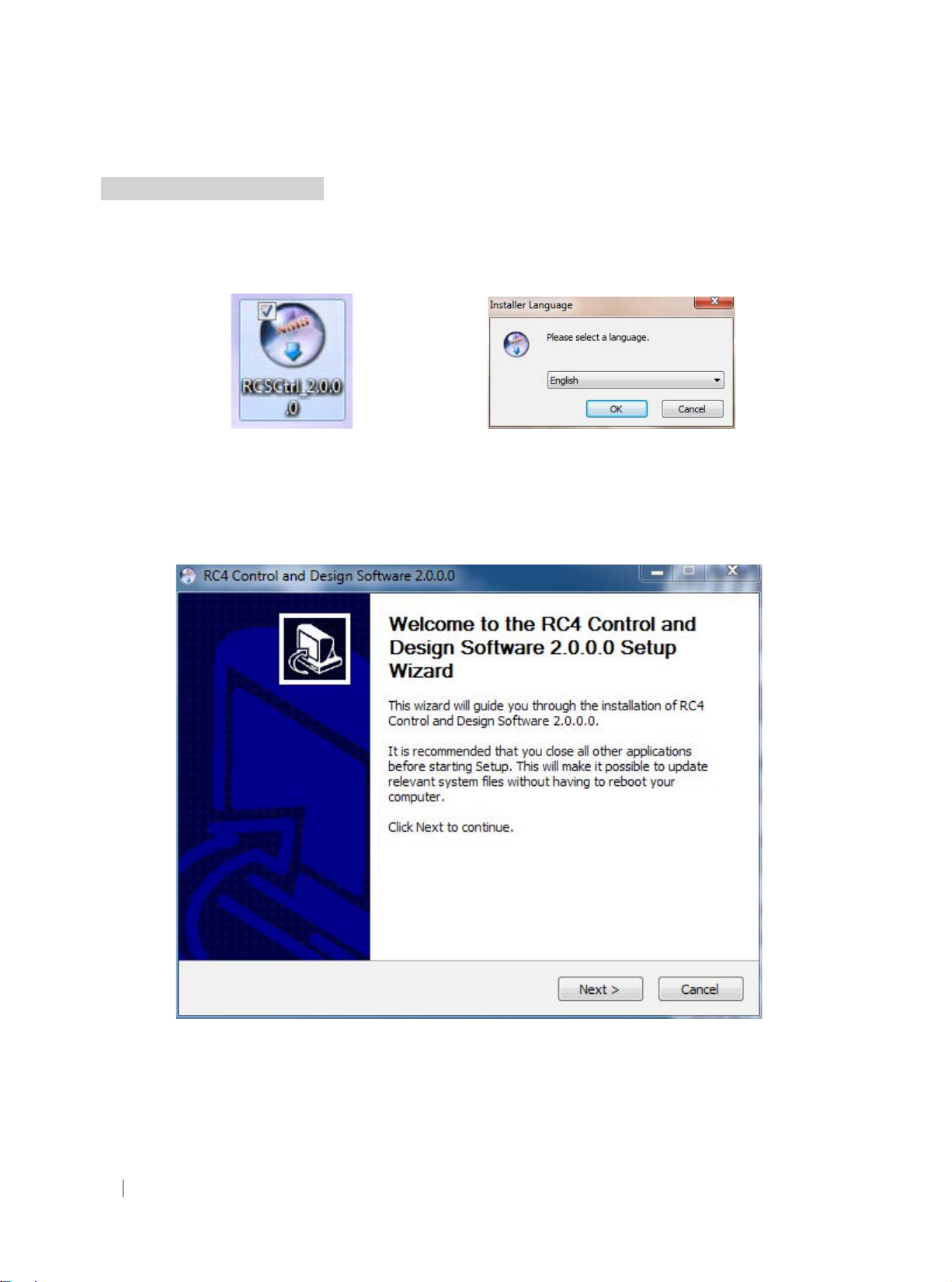
1. Copy the le “RCSCtrl_2.0” from the CD to your PC and double-click the icon in Figure 3.2.2 A.
2. Select the desired Language and then click “OK”, as shown above in Figure 3.2.2 B.
3. Follow the instructions on the Setup Wizard to complete the software installation, as demonstrated below:
Figure 3.2.2 A: RC4 software icon Figure 3.2.2 B: Select language
All rights reserved by DigiBird
14
Figure 3.2.2 C:RC4 software setup wizard
®
Page 16
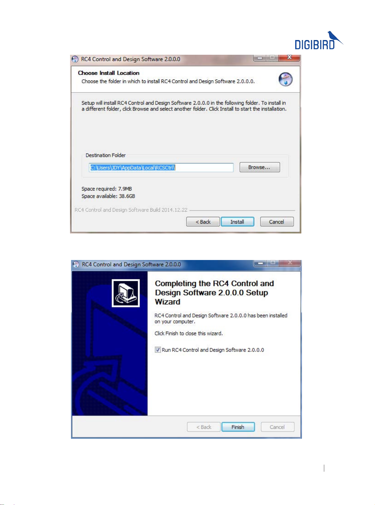
Figure 3.2.2 D: Choose install location
Figure 3.2.2 E: Finish
All rights reserved by DigiBird
®
15
Page 17
ideo & Image Processing
Research & Development, Manufacturing and Sales
V
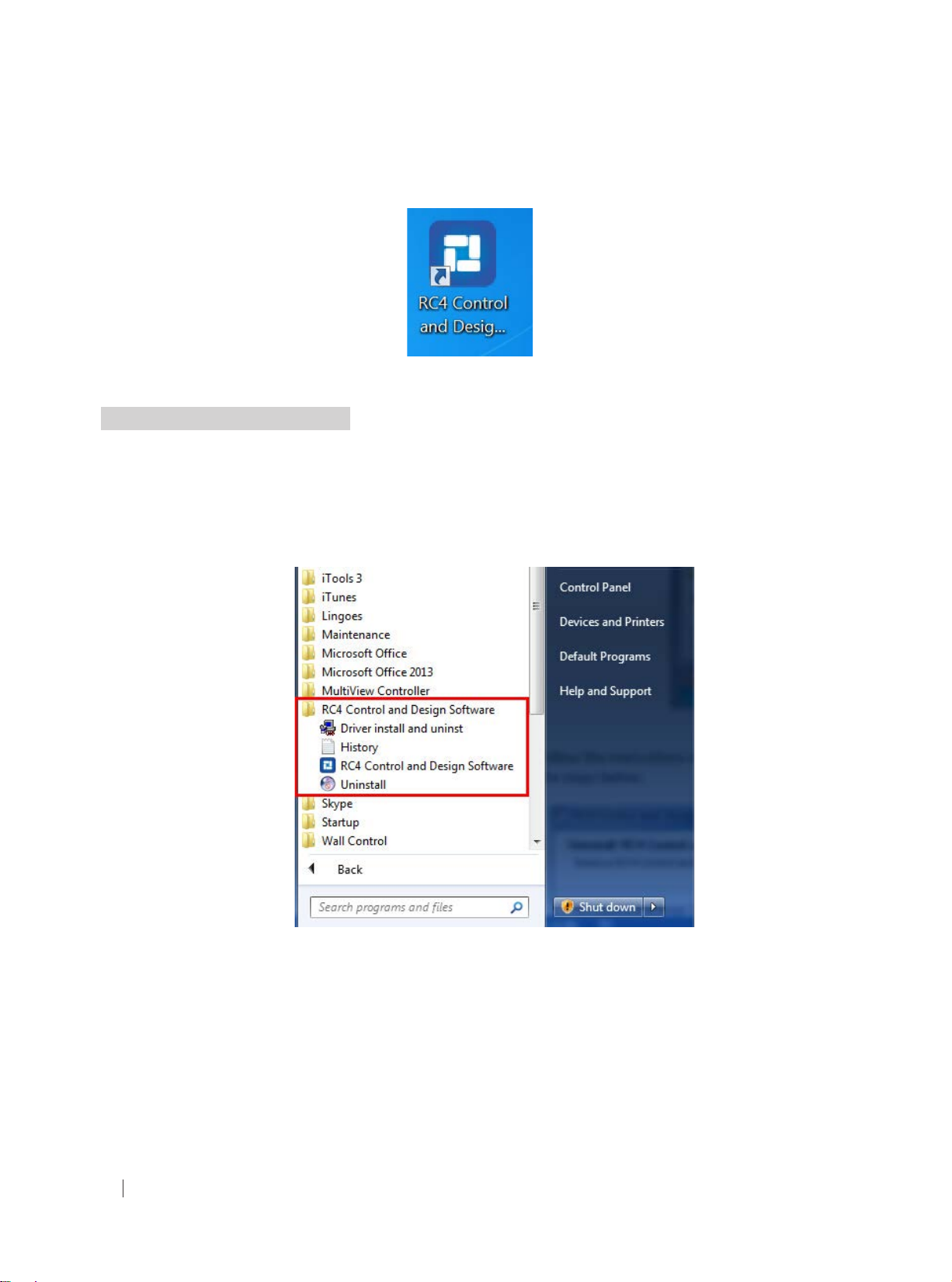
4. After the program is installed successfully, it will generate a shortcut on the desktop:
Figure 3.2.2 F: RC4 Control and Design software shortcut
3.2.3 Uninstalling the Software
The software uninstall steps are explained below:
1. Open the Start Menu by clicking the Start button and then click “All Programs” →“ RC4 Control and Design
Software” → “Uninstall”, as shown:
Figure 3.2.3 A: Uninstall
2. Follow the instructions on the Uninstall Wizard to complete the uninstall as shown in the steps below:
All rights reserved by DigiBird
16
®
Page 18
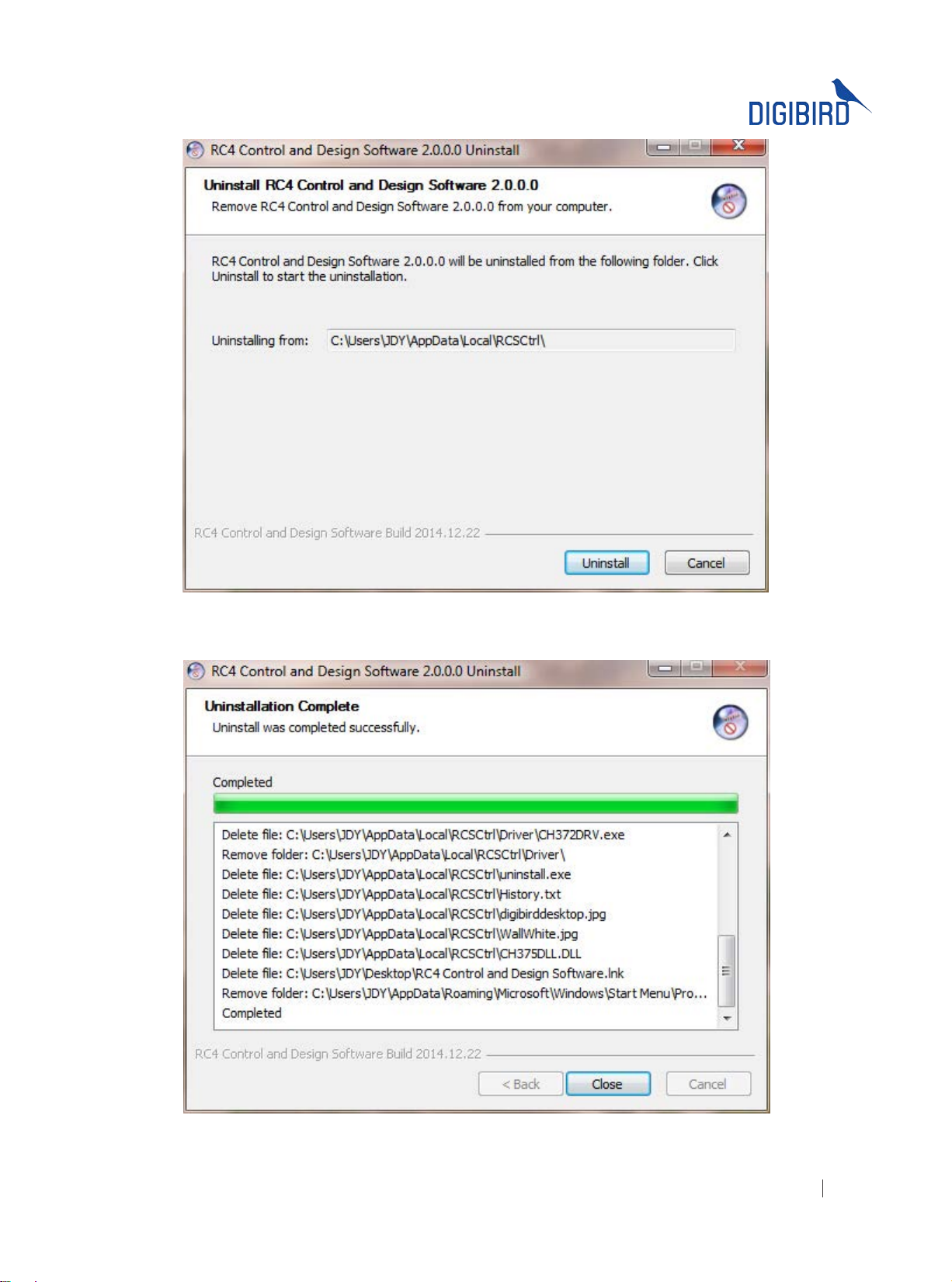
Figure 3.2.3 B: Uninstall
Figure 3.2.3 C: Uninstallation completed
All rights reserved by DigiBird
®
17
Page 19
ideo & Image Processing
Research & Development, Manufacturing and Sales
V
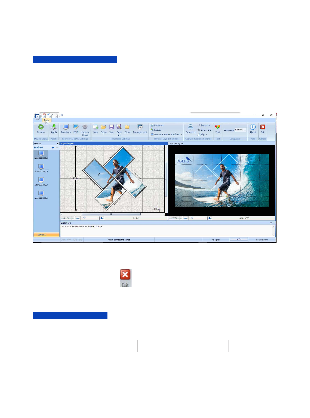
IV. Running the Software
Once the DB-RC4 v2 Control and Design Software has been installed, the user can run the application with any of the
following methods:
Double-click the DB-RC4 v2 icon (shortcut) on the desktop.
•
From the desktop, click Start > All Programs > RC4 Control and Design Software > RC4 Control and Software.
•
The opening screen below will appear:
Figure 4.0 RC4 Software Interface
You can exit the DB-RC4 v2 Control and Design Software using any of the following methods:
From the Main Menu, select Exit.
•
Or click the “Exit” button at the top left corner of the main application window.
•
V. Software Operation
This section contains the following topics:
Mounting Wall Size Setting Input Resolution Setting Monitors Setting
Physical Layout Design and Setting Capture Regions Settings EDID Management
Other Software Operations
All rights reserved by DigiBird
18
®
Page 20
5.1 Software Overview
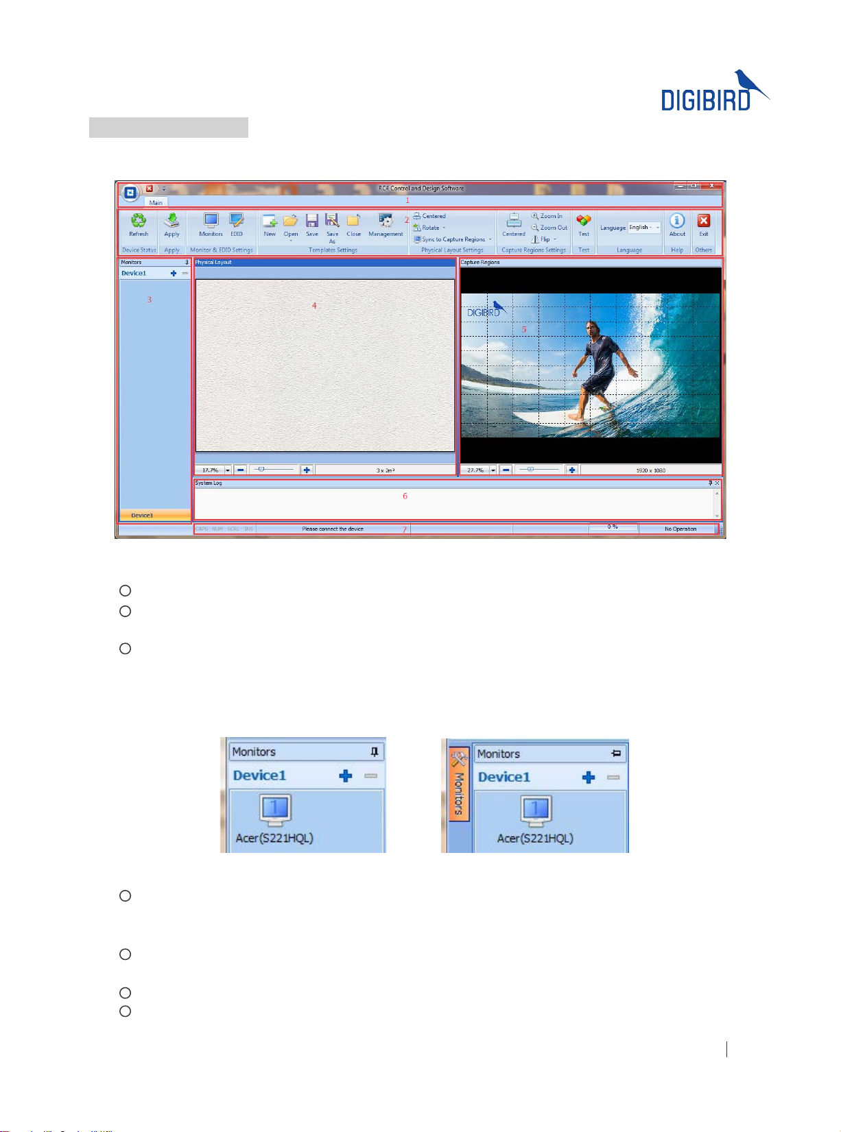
Prior to setup of the positions of monitors and capture regions, the user needs to be conversant with the software. The
DigiBird DB-RC4 v2 Control and Design Software application window contains the following elements:
1
Menu Bar: includes Start Menu and Customized Toolbars.
Toolbars: includes Conguration Templates, Physical Layout Settings, Capture Regions Settings, Test, Help and
2
Others.
3
Monitor Listing Window: the monitors list will be shown here after completing the Monitors Settings. The
trade names and models of the selected monitors will be displayed in the list. See below gure 5.1 B.
The Monitor Listing window can be docked or undocked. Look for the small pushpin in the title bar of the
Monitor Listing window and click it so that the pin is pointing to the left, as shown in the gure below. The
window will now automatically hide itself when it is not being used. See below gure 5.1 C.
4
Physical Layout Window: The background of the Physical Layout Window serves as the virtual area for which
video wall monitors will be mounted or placed. The monitors in the Physical Layout window can be dragged
and rotated in the custom designing of the video wall.
Capture Regions Window: The input signal (image or video) will appear here. The input signal can be cropped
5
and ipped in the Capture Regions window.
System Log Window: The system events will be displayed in the System Log window.
6
7
Status Bar: Includes Device ID, prompt message and Input Resolution, etc.
Figure 5.1 A: Software Overview
Figure 5.1B: Monitor list Figure 5.1 C: Undocked bar
All rights reserved by DigiBird
®
19
Page 21
ideo & Image Processing
Research & Development, Manufacturing and Sales
V
5.2 Mounting Wall Size Setting
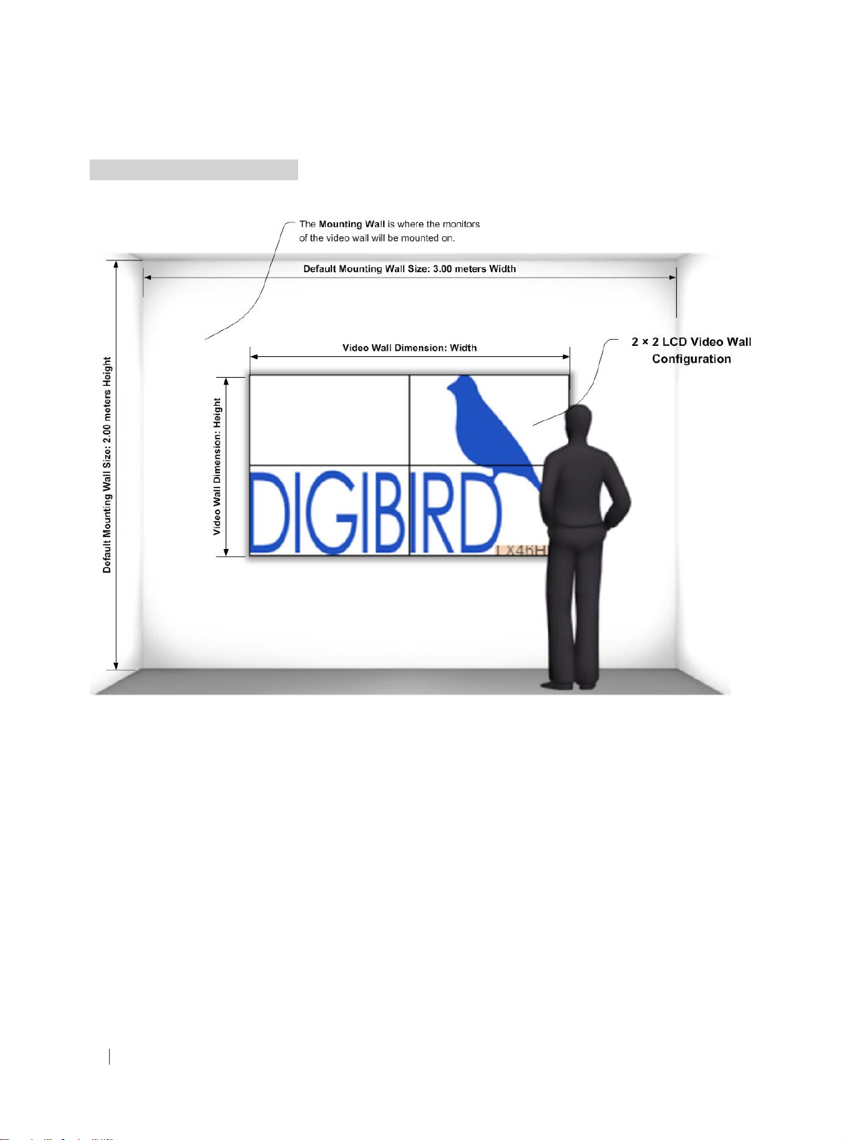
The Mounting Wall is the physical area where the actual video wall monitors will be mounted, or placed. (Figure 5.2 A).
Figure 5.2 A: Mounting Wall Size Setting
The default Mounting Wall dimension is 3.00 meters width by 2.00 meters height. Users can use the Mounting Wall
Size setting to dene the wall size according to on-site conditions.
To do this, hover your mouse cursor over the Physical Layout Window, and then right-click on the window background.
The Mounting Wall Size menu will appear. Left click to perform setup as shown in the gures below:
All rights reserved by DigiBird
20
®
Page 22
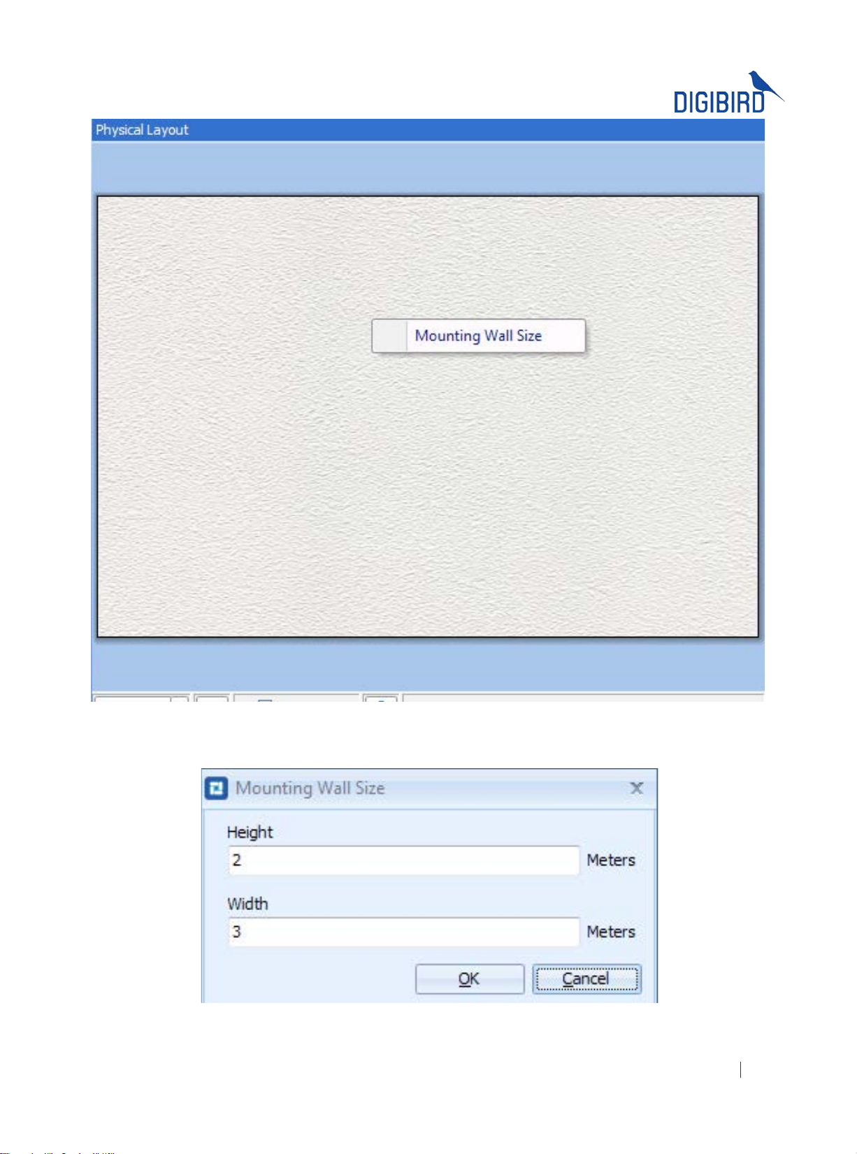
Figure 5.2 B: Mounting Wall Size
Figure 5.2 C: Height and width
All rights reserved by DigiBird
®
21
Page 23
ideo & Image Processing
Research & Development, Manufacturing and Sales
V
5.3 Input Resolution Settings
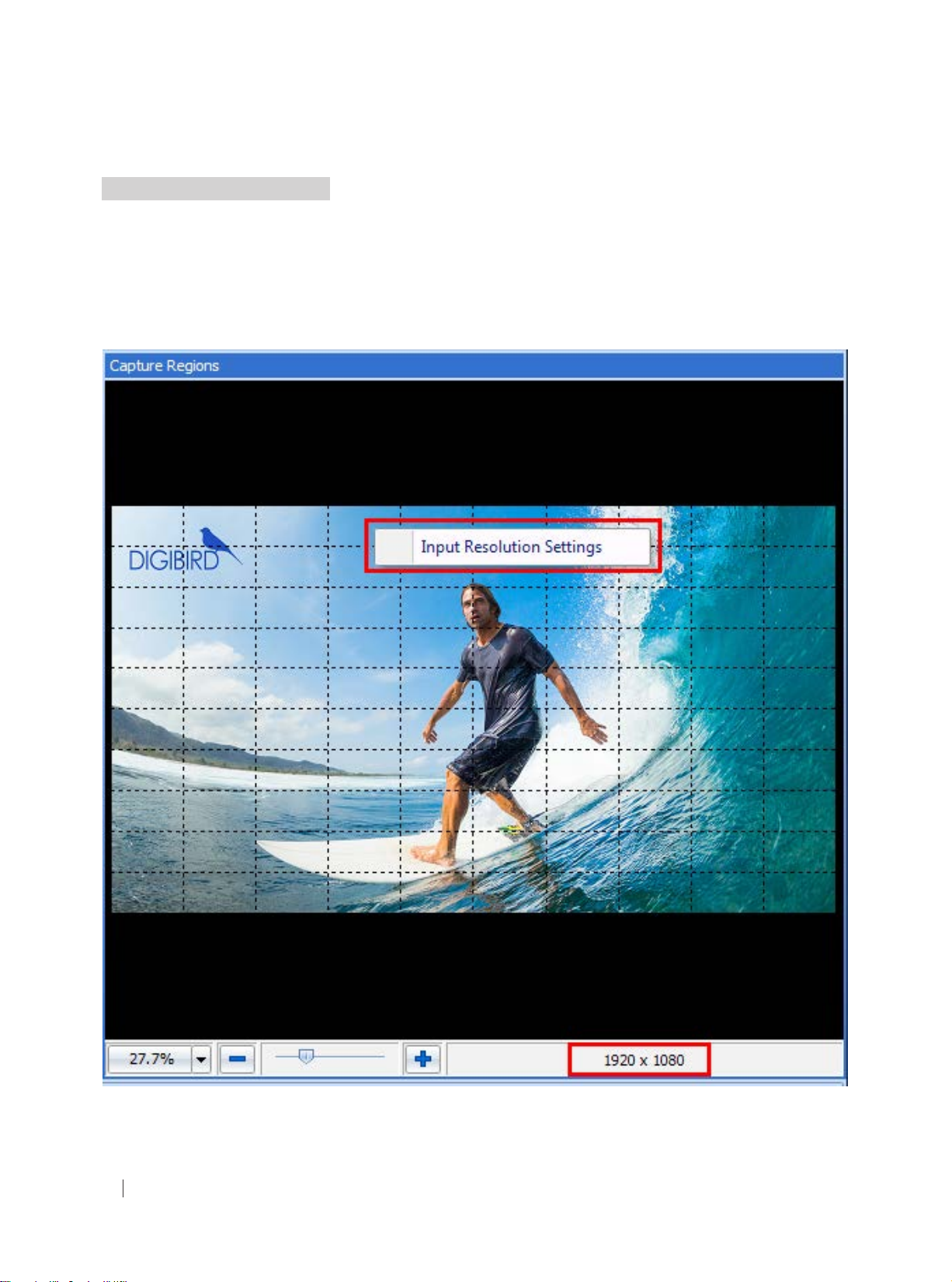
The default input resolution is 1920 × 1080 @ 60Hz. The user can change this default by selecting the Input Resolution
Settings menu.
Hover your mouse cursor over the background image of the Capture Regions Window and then right-click on the
background. The Input Resolution Settings menu will appear. Left-click it to enter the Input Resolution Settings, as
shown in the gures below: see gure 5.3 A.
All rights reserved by DigiBird
22
Figure 5.3 A: Default input resolutions
®
Page 24
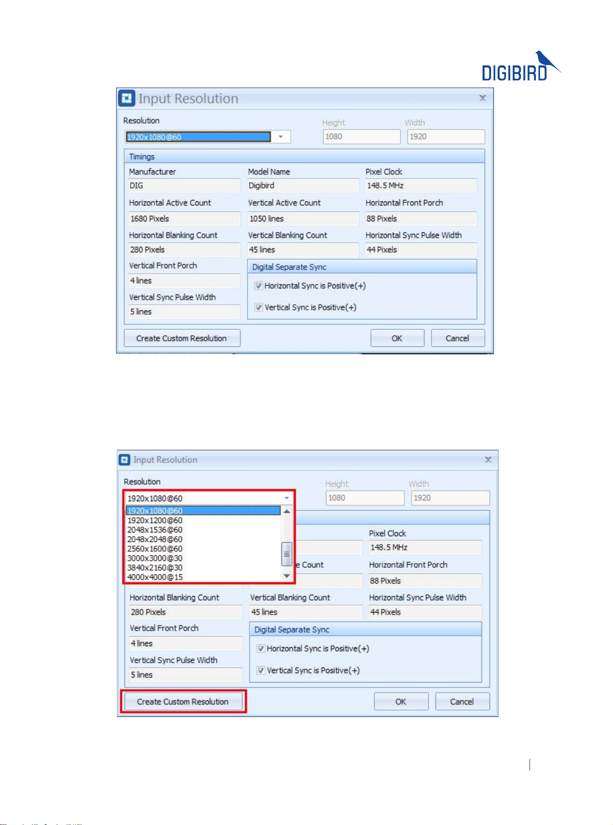
Figure 5.3 B: Resolutions dropdown list
Click the drop-down menu at the top left of the Input Resolution window and then select the desired input resolution.
(see Figure 5.3 B) If you’re unable to nd your desired resolution from the drop down list, you can select “Custom” at
the bottom of the list to create a custom resolution. After lling in the values of the resolution timing parameters, click
“Create Custom Resolution” and then press “OK”. The custom resolution will be created, as shown in the gure 5.3 C.
Figure 5.3 C: Create custom resolution
All rights reserved by DigiBird
®
23
Page 25
ideo & Image Processing
Research & Development, Manufacturing and Sales
V
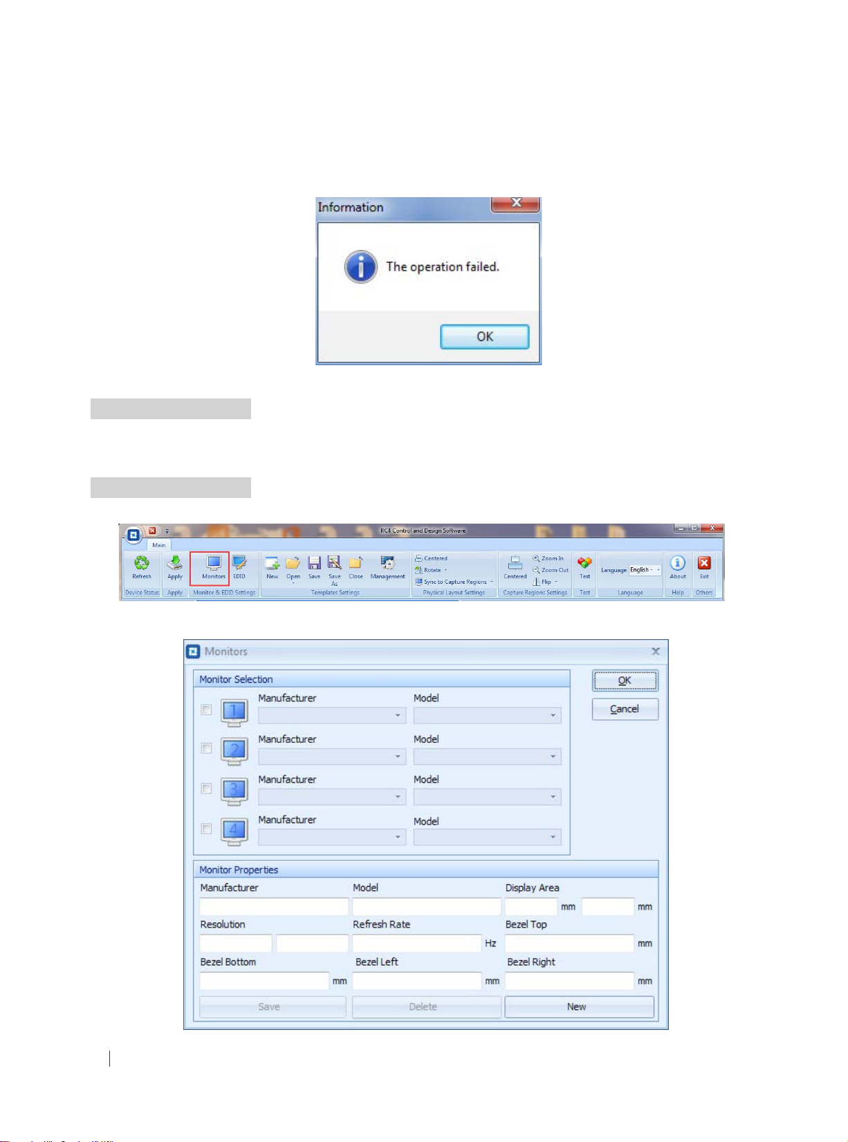
When clicking the “OK” button, a command will be sent to the DB-RC4 v2 device to adjust the input resolution. If it
fails to send the command, an information window will appear, as shown in the gure below:
Figure 5.3 D: The operation failed.
5.4 Monitor Settings
DigiBird’s DB-RC4 v2 Control and Design Software provides a monitor database which includes the most common
manufacturers and models.
5.4.1 Monitor Selection
In the Toolbar window, click the “Monitors” icon to open the “Monitors” setting window, as shown in the gures below:
Figure 5.4.1 A: Monitor Selection
All rights reserved by DigiBird
24
®
Figure 5.4.1 B: Monitors selection
Page 26
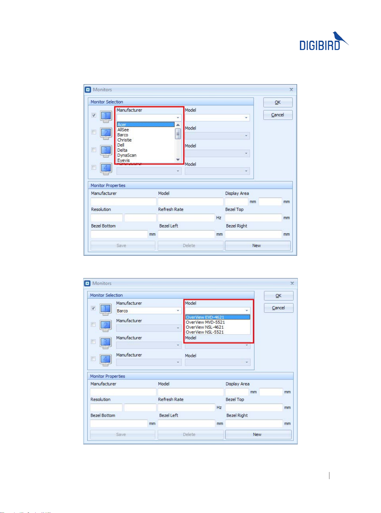
Click the check boxes at the left of the Monitors setting window to add the monitors being used. Select the
Manufacturer and Models dropdown lists to choose a specific, listed monitor. Refer to the following figures for
reference:
Figure 5.4.1 C: Manufacturer Dropdown List
Figure 5.4.1 C: Models Dropdown List
After the manufacturer and model selection, data will appear in the Monitor Properties window. The Monitor Properties
All rights reserved by DigiBird
®
25
Page 27
ideo & Image Processing
Research & Development, Manufacturing and Sales
V
are a group of specications that are required by the software to ensure the device is congured correctly. The Monitor
Properties include the following information: Manufacturer, Model, Display Area, Resolution, Refresh Rate, Top Bezel,
Bottom Bezel, Left Bezel and Right Bezel.
5.4.2 Adding New Monitors
If a monitor being used in the design of your video wall is not listed in the database, you can manually add the desired
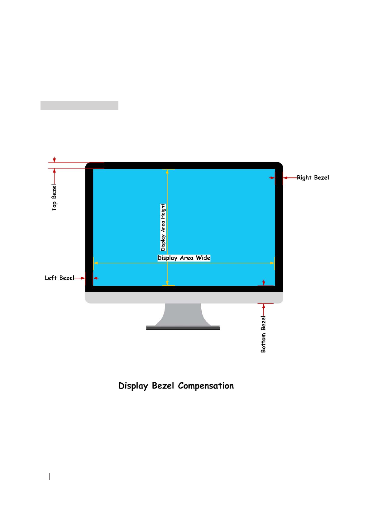
monitors by lling in the required values to the Monitor Properties elds using the manufacturer’s datasheet.
If you cannot nd the parameters in the display datasheet, measure the parameters accor
ding to the following gures:
After lling in the required values, click the Save Details button at the bottom left of the Monitors setting window. The
new monitor will appear in the manufacturer and models dropdown list, as shown in the gure below:
All rights reserved by DigiBird
26
®
Page 28
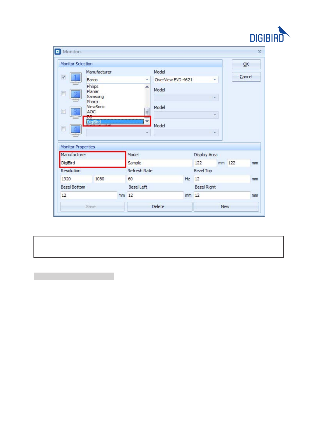
Figure 5.4.2 Added monitor
NOTE: It is very important that the specications of the monitors are accurate so as to ensure the capture regions
are calculated correctly.
5.4.3 Delete a Custom Monitor
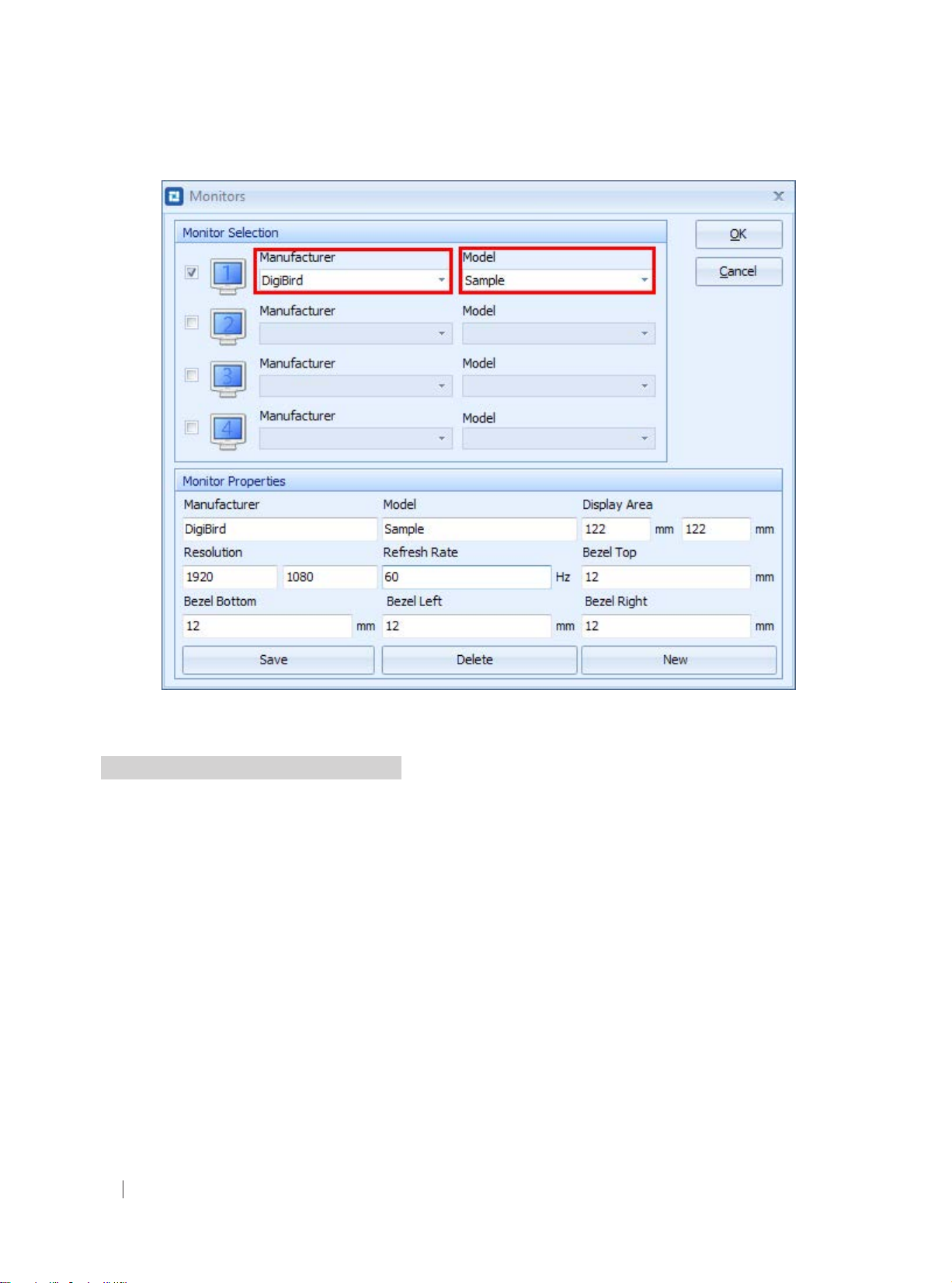
Select the custom manufacturer and model and click the Delete button. The custom monitor will be deleted from the
monitor database, as shown in the gure below:
All rights reserved by DigiBird
®
27
Page 29
ideo & Image Processing
Research & Development, Manufacturing and Sales
V
Figure 5.4.3 Delete a custom monitor
5.5 Physical Layout Design and Settings
Once the desired models have been selected and displayed in the Monitor Listing window, the user can proceed to the
Physical Layout window and Capture Regions window to design a creative video wall. The Physical Layout window will
display the physical position of the monitors with numbers (1, 2, 3 and 4) for cross-referencing.
Click on a monitor to select it. When the selected the monitor is highlighted red, the monitor can then be dragged to a
specic area in the Physical Layout window.
Right click on a monitor to bring up the context menu. This allows you to change its rotation or to sync the operation
to the Capture Regions, as shown in the gures below.
All rights reserved by DigiBird
28
®
Page 30
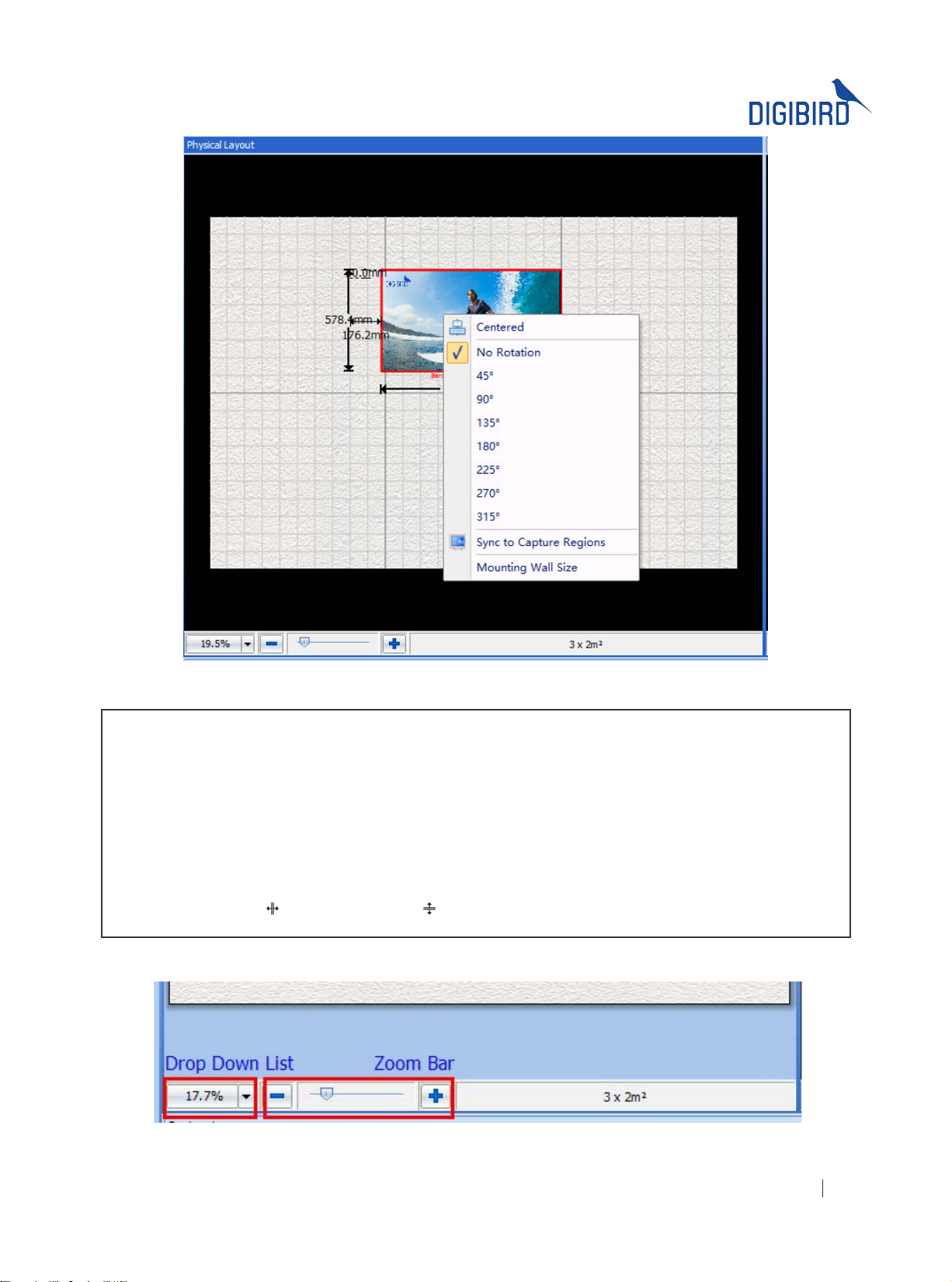
Figure 5.5 A: Physical layout design and settings
NOTE:
I. After selecting a monitor, the user can use the arrow keys on his keyboard to move the monitor one pixel at a
time.
II. Use the Ctrl key + arrow key to move the monitor ten pixels at a time.
III. The methods of alteration for the display proportion include: (see Figure 5.5 B):
a. Choose from the drop down list
b. Left-click the slider in the zoom bar and drag it to the left to zoom out; drag to the right to zoom in
c. Sliding the mouse wheel
d. Using the col-resize
or row-resize cursor
Figure 5.5 B: Display proportion
All rights reserved by DigiBird
®
29
Page 31
ideo & Image Processing
Research & Development, Manufacturing and Sales
V
5.5.1 Toolbar for Physical Layout Settings
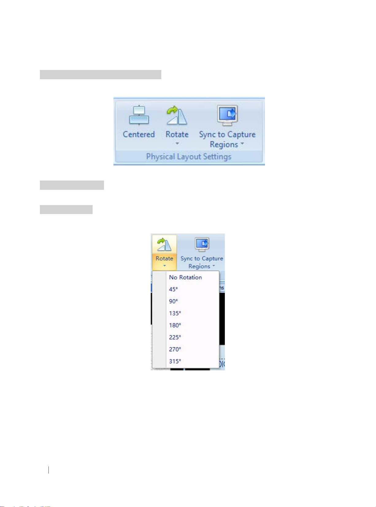
The Toolbar for the Physical Layout includes three icons: “Centered”, “Rotate” and” Sync to Capture Regions”.
Figure 5.5.1 Physical layout settings
5.5.2 Centered Icon
When clicking the Centered icon, the group of monitors will be placed in the middle of the Mounting Wall.
5.5.3 Rotate Icon
When clicking the Rotate icon, a drop down list will appear. The user can choose the desired Rotation angle from the
drop down list.
Figure 5.5.3 A: Rotate
Below is an example of a video wall conguration. Monitor #1 is rotated clockwise 45°; Monitor #2 is rotated clockwise
135°; Monitor #3 is rotated clockwise 315°; Monitor #4 is rotated clockwise 225°. This kind of video wall conguration
is commonly referred to as a “Windmill” layout:
All rights reserved by DigiBird
30
®
Page 32
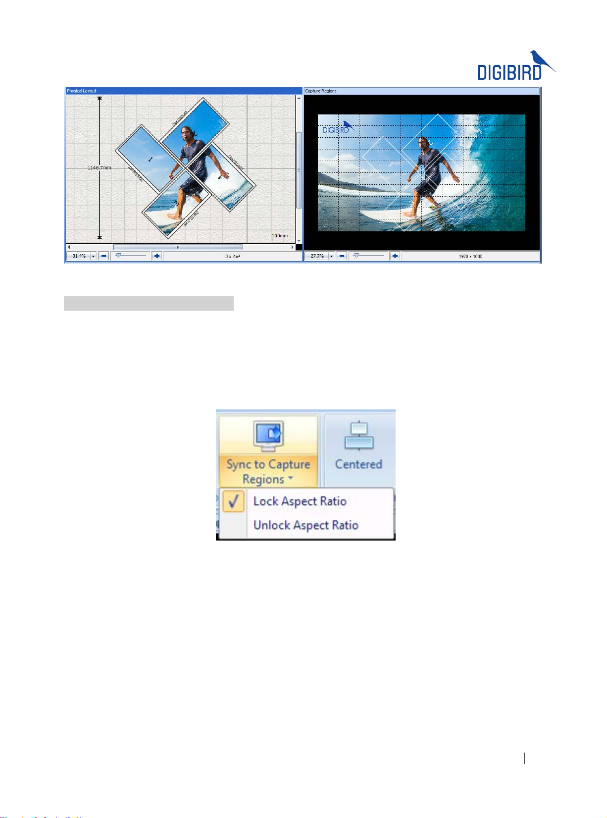
Figure 5.5.3 B: “Windmill” layout
5.5.4 Sync to Capture Regions Icon
The Sync to Capture Regions function allows the software to automatically calculate the pixel size and position of the
capture regions in the input source or the background picture according to the actual physical size and position of the
monitors on the mounting-wall.
When clicking the Sync to Capture Regions icon, a drop down list will appear. The user can choose one of two modes
of synchronization from the drop down list, Lock Aspect Ratio or Unlock Aspect Ratio.
Figure 5.5.4 A: Sync to capture regions
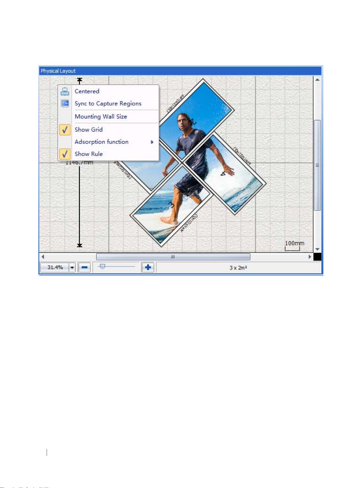
Right clicking on the Physical Layout window will make the context menu appear, which includes the following options:
Centered, Sync to Capture Regions and Mounting Wall Size.
All rights reserved by DigiBird
®
31
Page 33
ideo & Image Processing
Research & Development, Manufacturing and Sales
V
Figure 5.5.4 B: Context menu bar of Physical Layout
Right click on a monitor in the Physical Layout window. The context menu will appear, as shown in the gure below.
All rights reserved by DigiBird
32
®
Page 34
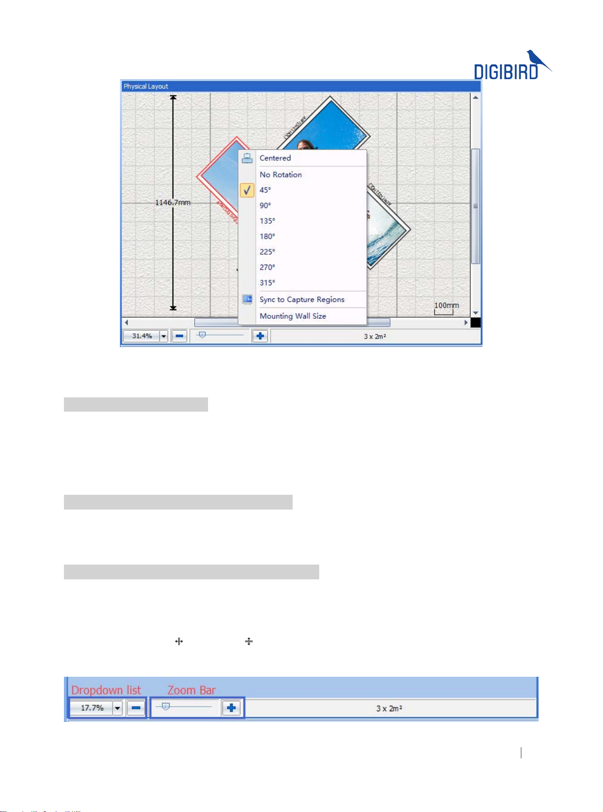
Figure 5.5.4 C: Context menu bar of monitor
5.6 Capture Regions Settings
The Capture Regions section of the software allows the user to attach an input and allocate regions to each monitor on
the video wall. The Capture Regions window allows the user to manually set and adjust each separate capture region.
After setting up the monitors in the Physical Layout window, the input source, in this example the default background
image of the surfer, is displayed over the main Capture Regions window with the capture regions of each monitor
overlain.
5.6.1 Moving and Resizing the Capture Regions
Capture regions can be moved and resized by clicking and dragging. Selecting a capture region will bring it to the
front and highlight it red. Capture Regions can also be selected by clicking the corresponding monitor in the Physical
Layout window.
5.6.2 Zooming in or out the Capture Regions Window
Use the following methods to zoom in or out the Capture Regions window:
Choose from the drop down list (Figure 5.6.2 A)
•
Left-click the slider in the zoom bar, and drag it to the left to zoom out and to the right to zoom in (Figure
•
5.6.2 A)
Slide the mouse wheel
•
Use the col-resize
•
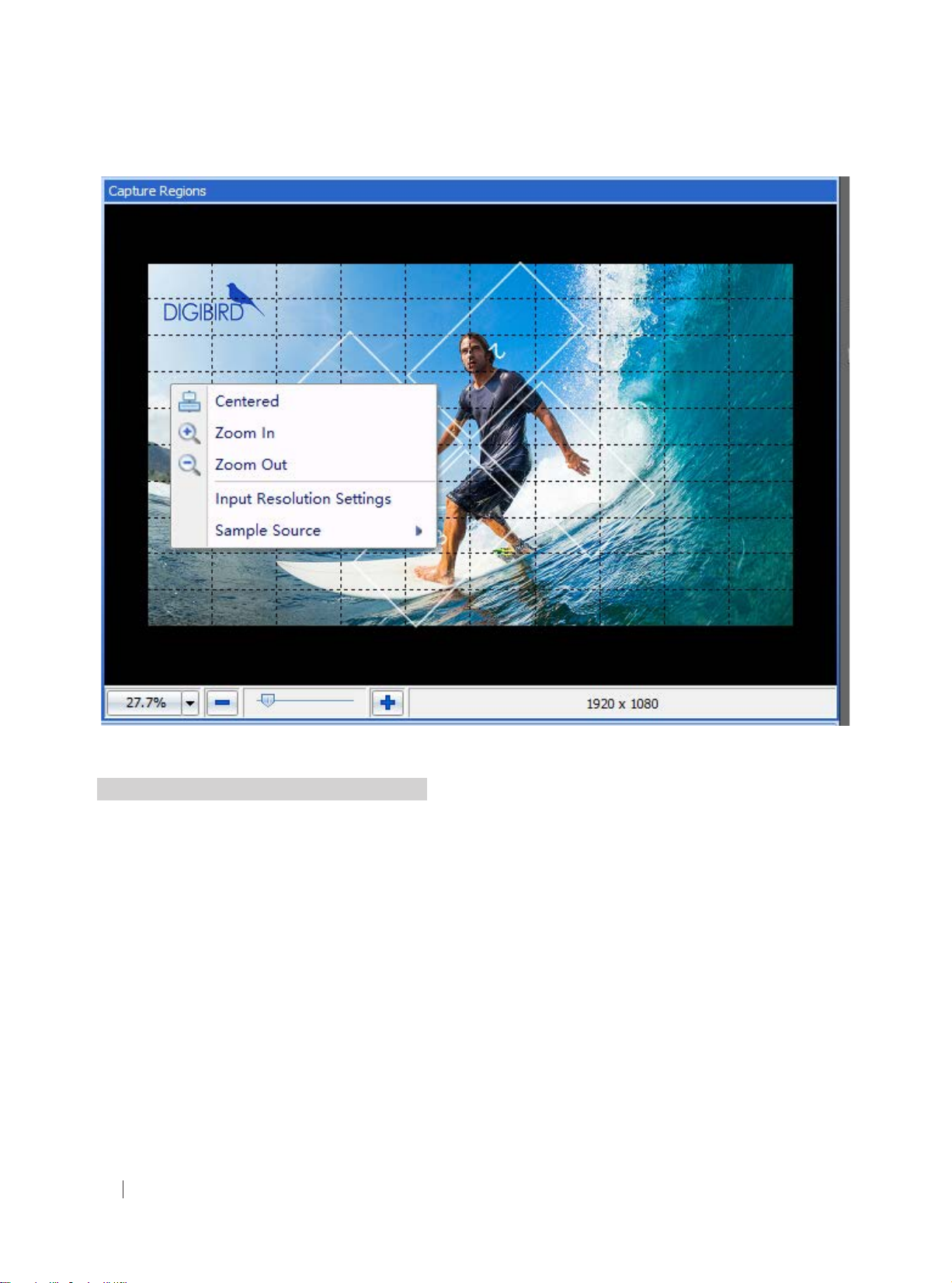
Hover the mouse cursor over the blank area of the Capture Regions window, right click, and the context menu
•
will appear
or row-resize cursor
Figure 5.6.2 A: Dropdown list and Zoom Bar
All rights reserved by DigiBird
®
33
Page 35
ideo & Image Processing
Research & Development, Manufacturing and Sales
V
Figure 5.6.2 B: zoom in/out
5.6.3 Context Menu of the Capture Regions
Hover the mouse cursor over the capture region and right click. The context menu will appear, as shown below:
All rights reserved by DigiBird
34
®
Page 36
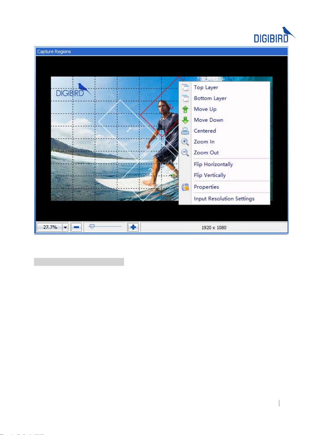
Figure 5.6.3 Context menu bar of the Capture Regions
5.6.4 Layering the Capture Regions
When the Capture Regions overlap, they are layered. The default layer priority overlapping from bottom to top starts
at monitor No. 1 at the bottom, layering sequentially to monitor No. 4 at the top. The user can change the layer priority
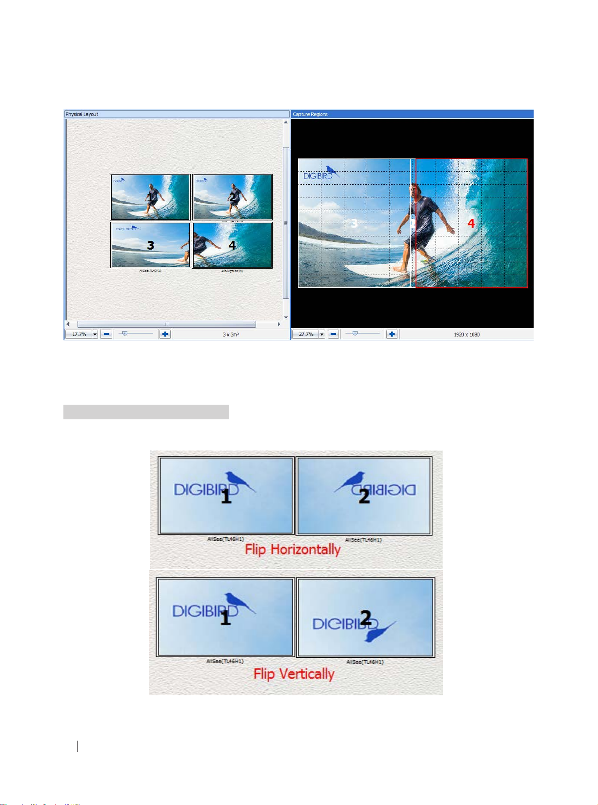
of the capture regions by selecting Top Layer, Bottom Layer, Move Up and Move Down.
Below is an example of how to use the layering function to design a video wall:
All rights reserved by DigiBird
®
35
Page 37
ideo & Image Processing
Research & Development, Manufacturing and Sales
V
Figure 5.6.4 Layering the Capture Regions
Monitors No. 1 and No. 2 display the entire input source on each monitor. No.1 Capture Region is the bottom layer of
the Capture Regions window.
5.6.5 Flip Horizontally or Vertically
Choose Flip Horizontally or Flip Vertically from the above context menu. The resulting display of the monitors should
look like the following:
All rights reserved by DigiBird
36
Figure 5.6.5 Flip horizontally/ vertically
®
Page 38
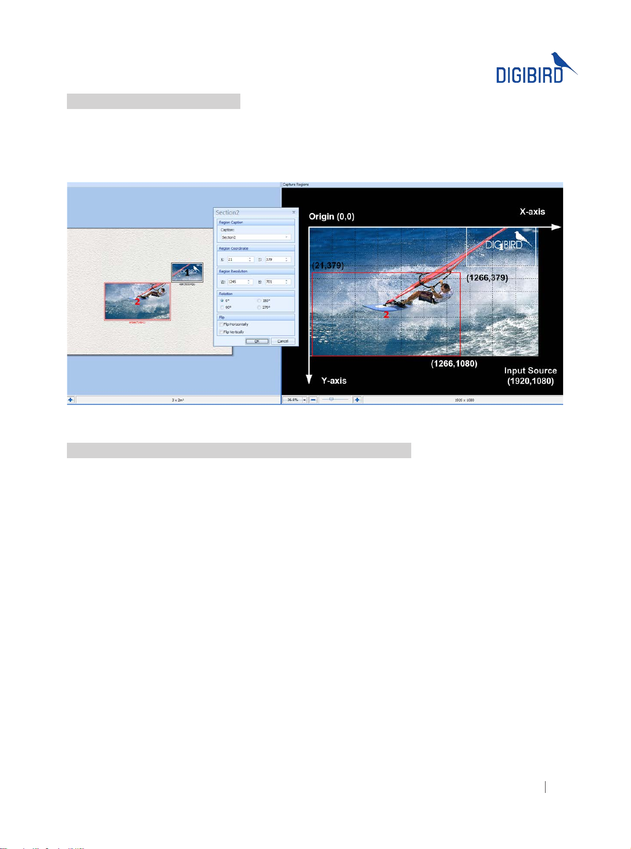
5.6.6 Capture Regions Properties
According to the physical position and size of the monitors, the software automatically calculates the pixel size of the
Capture Regions. Related information about the Capture Regions, including Region Coordinates, Region Resolution,
Region Rotation and Flip will be shown in the Capture Regions Properties box. The following gure (Figure 5.6.6) will
help the user to better understand the Capture Regions properties.
Figure 5.6.6 Capture regions properties
5.6.7 How to Calculate the Pixel Size and Position of a Capture Region
After positioning the monitors in the Physical Layout window and clicking the Sync to Capture Regions button, the
software will automatically calculate how many pixels the capture region and the corresponding monitor should have.
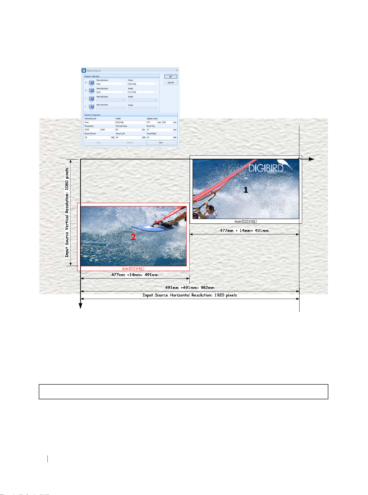
Below is a simple example to illustrate this calculation process:
Two Acer S221HQL monitors are positioned on the Mounting Wall. There is no gap between the two monitors, as
shown in the following gure:
All rights reserved by DigiBird
®
37
Page 39
ideo & Image Processing
Research & Development, Manufacturing and Sales
V
Figure 5.6.7 A: Calculations
First of all, calculate the physical size of the video wall in the horizontal direction. The calculating formula is shown
below:
Screen Width + Right Bezel +Left Bezel +Screen Width= 477+14+477+14= 982mm
Second, divide the horizontal resolution by the horizontal physical size to get the number of pixels per millimeter.
NOTE: The default input resolution is 1920 × 1080@60Hz.
1920 pixels/982 mm= 1.9552 pixels/mm
Third, calculate how many horizontal pixels the No. 2 monitor should have by using the following formula:
Viewable Width × 1.9552 pixels/mm= 477mm × 1.9552 pixels/mm= 932 pixels
All rights reserved by DigiBird
38
®
Page 40
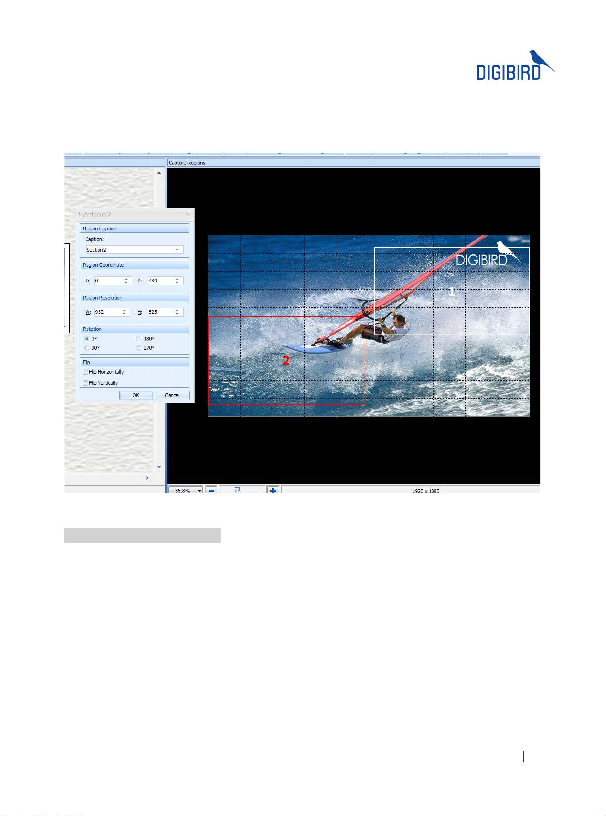
Now we can use the Capture Regions Settings to check the calculation. Hover the mouse cursor over Region 2,
right click, and the context menu will appear. Choose the “Properties” option, and the Region Properties window
(Section Properties) will appear. Check the Region Resolution--region two is 932 pixels wide, which is the same as the
calculation.
Figure 5.6.7 B: Position
5.7 Adding a Device (DB-RC4 v2)
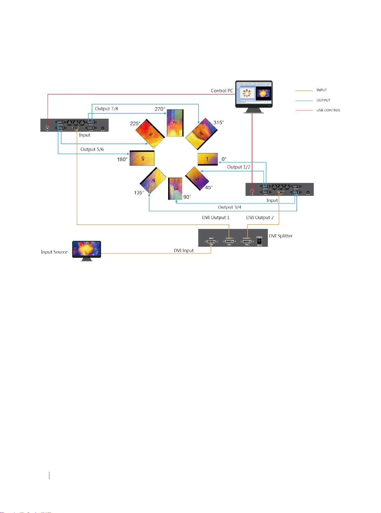
If large video walls are required for your solution (more than four monitors or displays), you can add additional DB-RC4
v2 devices by connecting them with a DVI splitter and then adding them on the software. The DVI splitter distributes
the input source across all of the connected DB-RC4 v2s. The following diagram shows how to create such a video wall
conguration with multiple DB-RC4 v2s.
All rights reserved by DigiBird
®
39
Page 41
ideo & Image Processing
Research & Development, Manufacturing and Sales
V
Figure 5.7 A: Cascaded devices layout
Add or delete the DB-RC4 v2 devices by clicking the Plus (+) icon or Subtract (-) icon on the Monitor Window, as shown
below. After that, the selected monitors on the Physical Layout Window and the selected Capture Regions on the
Capture Regions Window can be moved by clicking and dragging them.
All rights reserved by DigiBird
40
®
Page 42
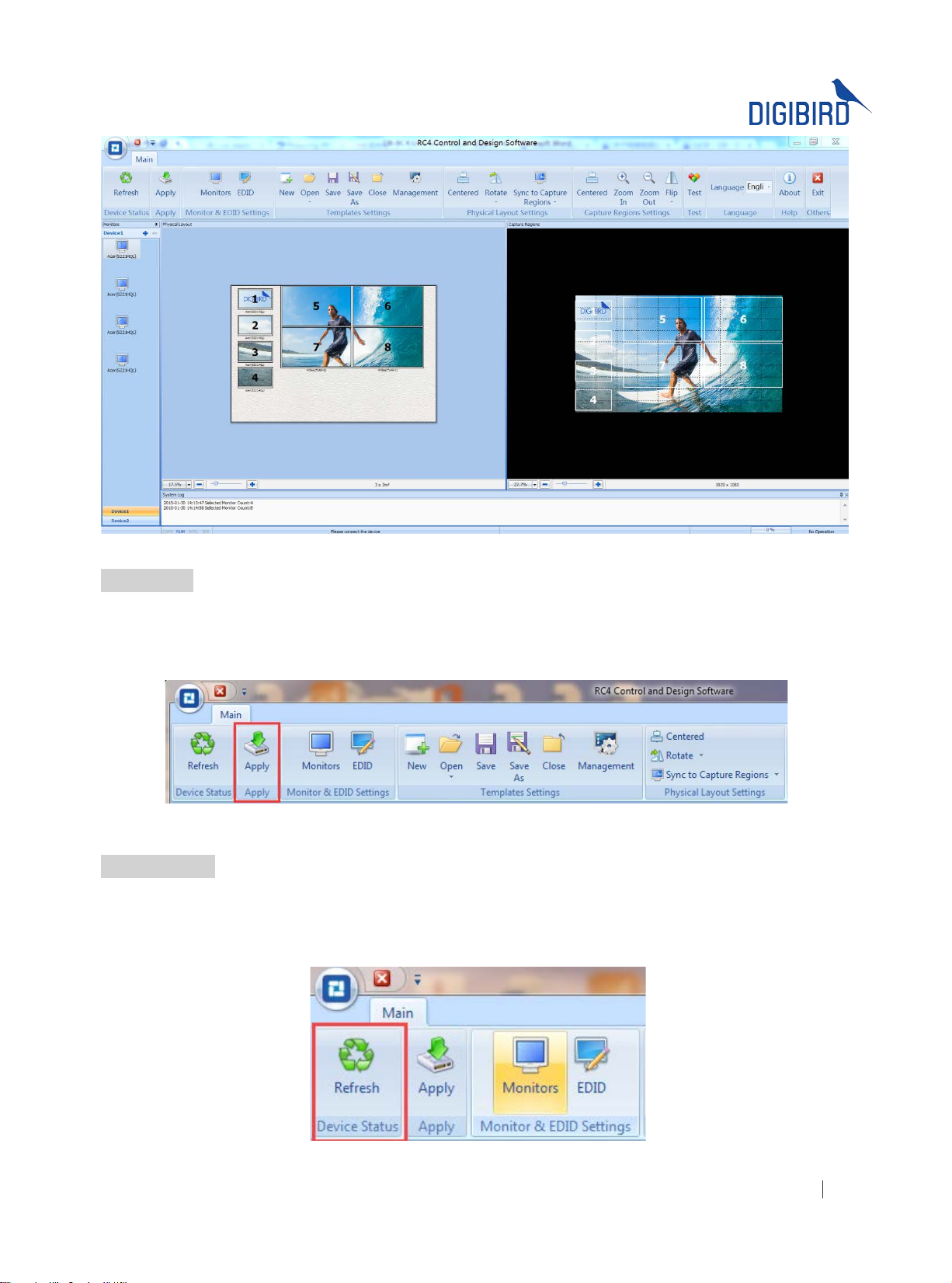
Figure 5.7 B: Adding devices
5.8 Apply
After setting up the Monitors and Capture Regions and connecting the DB-RC4 v2 hardware, click the “Apply”
icon in the Toolbar. The software will send the conguration template to the device (DB-RC4 v2 hardware) and the
conguration will take effect.
Figure 5.8 Apply
5.9 Refresh
Click the Refresh icon in the Toolbar to check the resolution of the connected input source. The software will detect
whether the input resolution that the user set up matches the resolution of the connected input source. If it is not a
match, the software will give notices to remind the user to adjust the input resolutions.
Figure 5.9 Refresh
All rights reserved by DigiBird
®
41
Page 43
ideo & Image Processing
Research & Development, Manufacturing and Sales
V
5.10 Conguration Template Management
The conguration template of the video wall, including the position of the monitors, rotation of the monitors, input
resolution, etc., can be stored as non-volatile memory so that you can recall them at any time without fear of losing
them due to power failure.
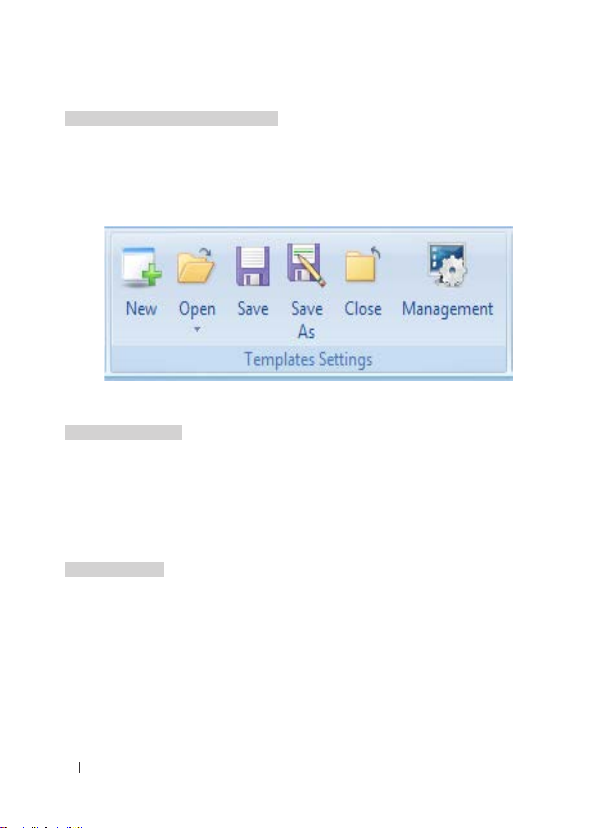
The operation of the Conguration Template includes New, Open, Save, Save As, Close and Management, as shown
below:
Figure 5.10 Templates Settings
5.11 EDID Management
The software supports EDID management by enabling the user to read the input EDID information and the output
EDID information (Display side), and save the output EDID to the DB-RC4 v2 or perform a ‘Save As’, saving the EDID
information to le.
Timing: Used to display the manufacturer information like model name, pixel clock, horizontal active count, vertical
active count, horizontal front porch, horizontal blanking count, vertical blanking count, horizontal sync pulse width,
vertical front porch, vertical sync pulse width, etc.
5.11.1 Read EDID
Select Input or Output source and click “Read EDID”. The EDID (Extended Display Identication Data) properties will
be displayed in the Timings box. See the example below:
All rights reserved by DigiBird
42
®
Page 44
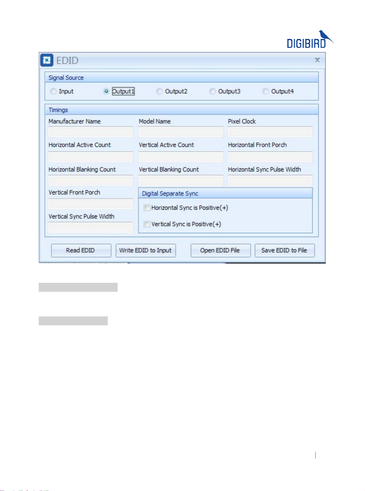
Figure 5.11.1 Read EDID
5.11.2 Write EDID to Input
The software supports the writing of EDID information to the input. The user needs to click the “Read EDID” button
prior to writing the EDID to the input.
5.11.3 Open EDID File
Press “Open EDID File” to import the user-saved EDID le.
All rights reserved by DigiBird
®
43
Page 45
ideo & Image Processing
Research & Development, Manufacturing and Sales
V
5.12 Test
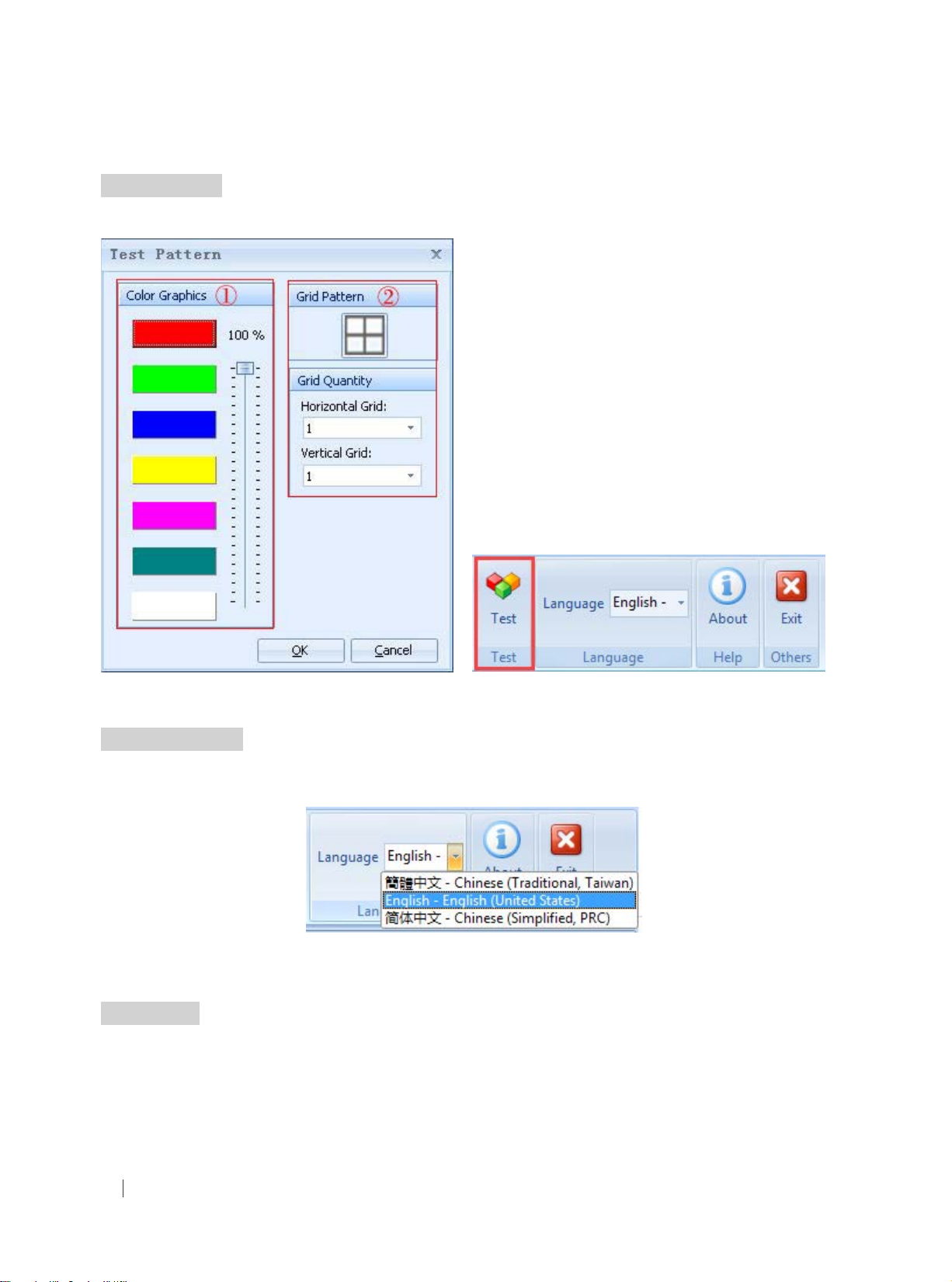
Use the Test Pattern to display color bars or grid in the monitors for testing signals, as shown in the following gure:
5.13 Language
The software is multilingual, currently supporting English, Chinese Simplied and Chinese Traditional.
5.14 About
Click the “About” icon to show the version and copyright information.
Figure 5.12 B: Test pattern Figure 5.12 A: Test
Figure 5.13 Language Selection
All rights reserved by DigiBird
44
®
Page 46
 Loading...