

DigiBird DB-AVCLink User Manual

AV KVM Over Fiber Matrix Switcher
User Manual
Version 2017 V1

Contents
Contents
WELCOME 1
ABOUT THIS MANUAL 1
CAUTIONS AND NOTES 1
COPYRIGHT 1
TRADEMARKS 2
DISCLAIMER 2
INTRODUCTION 3
MATRIX DEVICE 3
FRONT PANEL 3
REAR PANEL 5
SET IP ADDRESS 7
OPTIC TRANSFER UNIT 8
SETUP 10
SOFTWARE 11
LOGIN 11
OVERVIEW 12
DASHBOARD 12
SETTINGS 13
SWITCH 13
KVM 15
SET KVM CHANNEL 15
OSD 16
PREVIEW OF CURRENT STATUS 21
SCENE 21
SAVE 21
PREVIEW 22
RECALL 23
RENAME 23
DELETE 23

Contents
PORT CONFIGURATION 23
CONFIGURE PORTS 24
RENAME THE PORT 25
KVM STATUS 25
AUDIO CONFIGURATION 26
RESOLUTION 26
ALARM 29
USERS 30
ADD A USER 30
AUTHORITIES 31
EDIT 34
DELETE 34
BACKUP AND RESTORE 35
BACKUP 35
RESTORE 36
UPGRADE 38
FACTORY CONFIGURATION 38
RUNNING RATE 39
SINGLE FIBER MODE 39
FACTORY CONFIG 40
LICENSE 41
APPENDIX 42
GLOSSARY 42

Welcome
1
Welcome
About This Manual
This Manual is applicable to AVCLink (AV KVM Over Fiber Matrix Switcher). Thank you
for choosing DigiBird, please read this manual carefully before using the product.
All pictures in this manual are only for reference, information in this document is subject
to change without notice.
Cautions and Notes
The following symbols are used in this manual:
Notes
The necessary hints, additions and explanations to help you to understand the con-
tent of the manual more clearly.
Cautions
This symbol indicates best practice information to show recommended
and appropriate manner to use this product efficiently.
Warnings
The important operating instruction that should be followed to avoid any potential
damage to hardware or property, data loss, or personal injury.
The following spellings are used in this manual:
Spelling
Description
<key>
Description of a key on the keyboard
<key + key>
Press keys simultaneously
<key, key>
Press keys successively
[Menu item]
Description of a menu item in the software
Copyright
All rights reserved by DigiBird®, © 2017.
No portion of this manual may be reproduced in any manner without the prior written
consent of DigiBird®.

Welcome
2
Trademarks
All trademark and trade names mentioned in this document are acknowledged to be
the property of their respective owners.
Disclaimer
While every precaution has been taken during preparation of this manual, the manufacturer
assumes no liability for errors or omissions. The manufacturer assumes no liability for damages
resulting from the use of the information contained herein.
The manufacturer reserves the right to change specifications, functions, or circuitry of the product without notice.
The manufacturer cannot accept liability for damage due to misuse of the product or due to
any other circumstances outside the manufacturer’s control (whether environmental or instal-
lation related). The manufacturer shall not be liable for any loss, damage, or injury arising directly, indirectly, incidentally, or consequently from the use of this product.
Introduction
3
Introduction
DB-AVCLink is a powerful KVM matrix switcher, which completely transmits audio,
video and KVM signal via fiber optical or twist pair without losses and latency, widely
used in application of utility, security, government, and financial industry, etc.
DB-AVCLink consists of Matrix Device and Optic Transfer Unit. The chassis sizes are 8U
and 26U; and the Optic Transfer Unit means Transmitter and Receiver.
Matrix Device
Front Panel
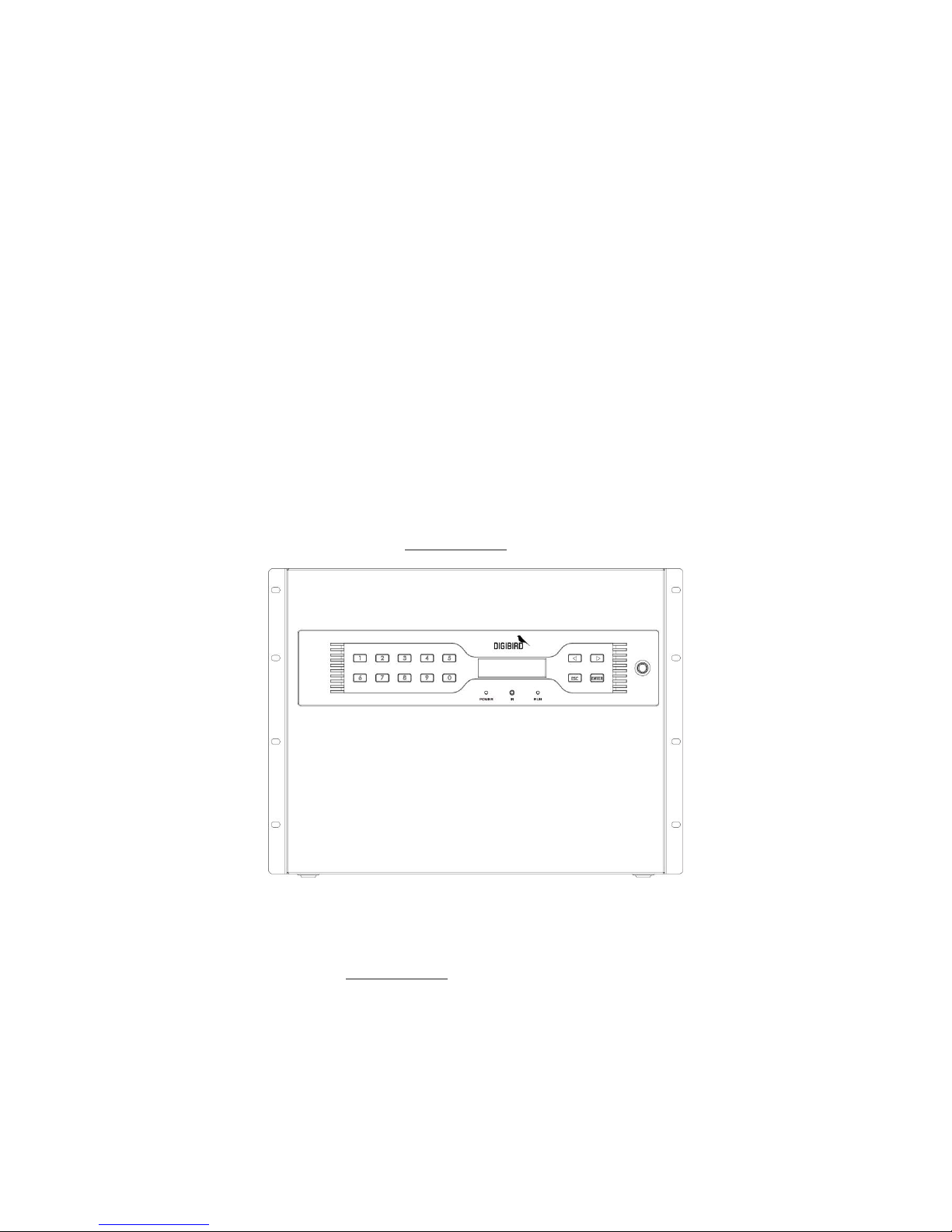
8U chassis (160x ports)
The front panel of the 8U chassis is shown as below. You are able to change the IP
address via the front panel,see Set IP Address for details.
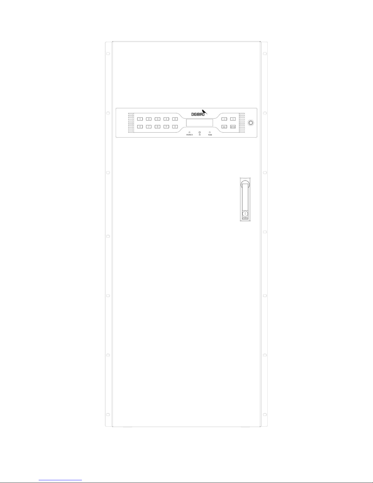
26U chassis (576x ports)
The Front Panel of 26U chassis is shown as below. You are able to change the IP address
via the front panel,see Set IP Address for details.
Introduction
4

Introduction
5
Rear Panel
The rear panel consists of below main slots:
Input / Output Port
Mixed dual-optical I/O ports, which can be defined to be input when connected
with the transmitter/ Tx or to be output when connected with the receiver/Rx.
Input Slot
The slot to populate the input card, that includes eight (8x) pairs of dual-optical
ports to be connected with the transmitter/Tx.
Output Slot
The slot to populate the output card, that includes eight (8x) pairs of dual-optical
ports to be connected with the receiver/Rx.
CMC Slot
The Confidence Monitoring Slot to populate the CMC (Confidence Monitoring
Card) card for local monitoring.
Control Slot
Slot for control board. There are two control board to ensure the system running
as normal.Populated with Dual Control cards for backup.
Power Slot
The slot for the PSU (Power Supply Unit).
Fan Slot
The slot for the cooling fans with auto adjustment feature.
Please tighten the screws when insert the card into the slot.
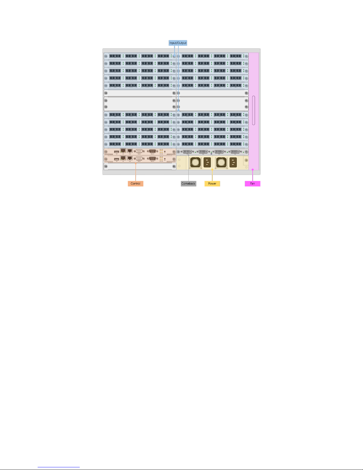
8U chassis (160x ports)
The 8U chassis includes twenty (20x) I/O slots (no matter input or output), two (2x)
control slots, one (1x) CMC slot, and two (2x) PSU slots.
Introduction
6
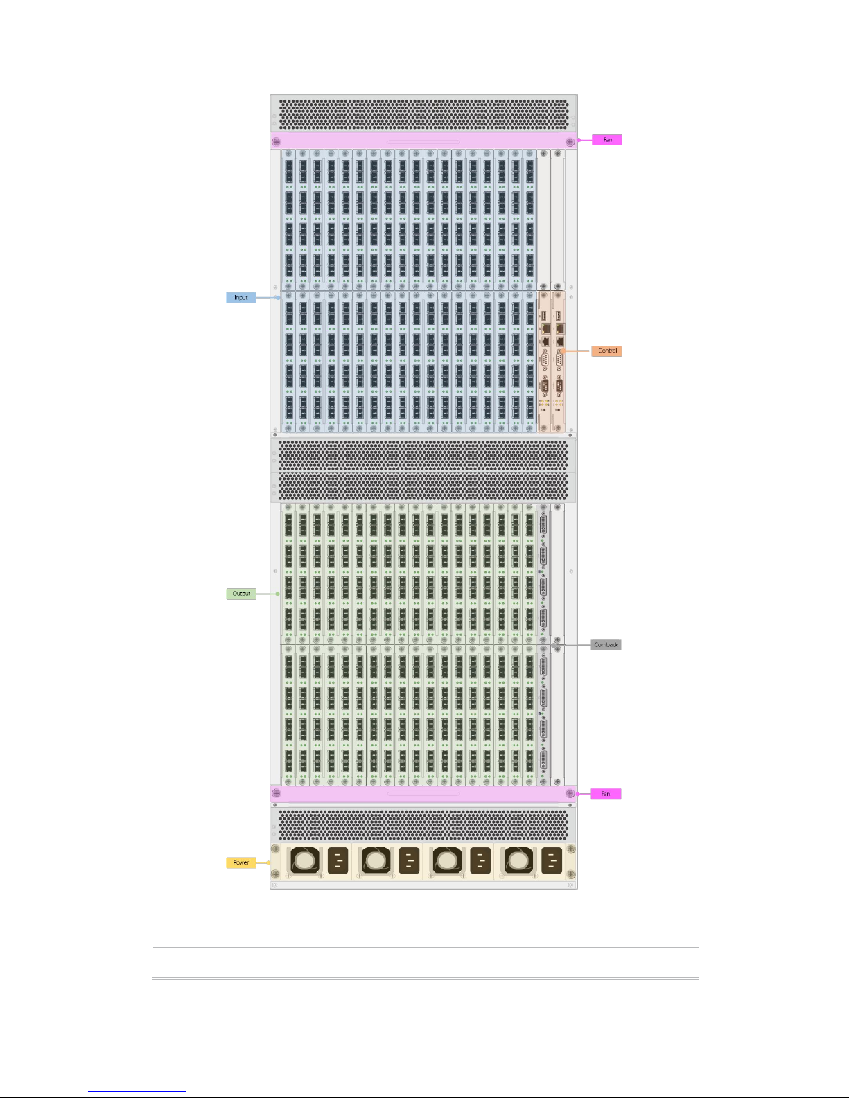
26U chassis (576x ports)
The 26U chassis includes thirty-six (36x) input slots, thirty-six (36x) output slots, two
(2x) control slots, one (1x) CMC slot, and two (2x) PSU slots.
Introduction
7
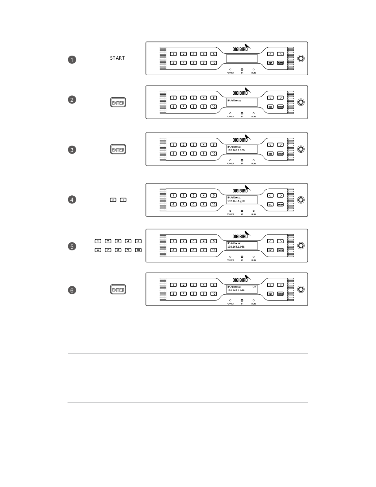
Set IP address
Operation
OSD
Introduction
8
Indicators
POWER
Power indicator.
IR
IR indicator. (Reserved for future use.)
RUN
RUN indicator: illuminate when operating normally.
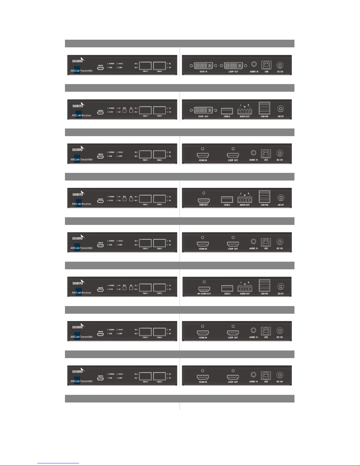
Optic Transfer Unit
Introduction
9
DVI Transmitter
Front Panel
Rear Panel
DVI Receiver
Front Panel
Rear Panel
HDMI Transmitter
Front Panel
Rear Panel
HDMI Receiver
Front Panel
Rear Panel
4K HDMI Transmitter
Front Panel
Rear Panel
4K HDMI Receiver
Front Panel
Rear Panel
DP Transmitter
Front Panel
Rear Panel
4K DP Transmitter
Front Panel
Rear Panel
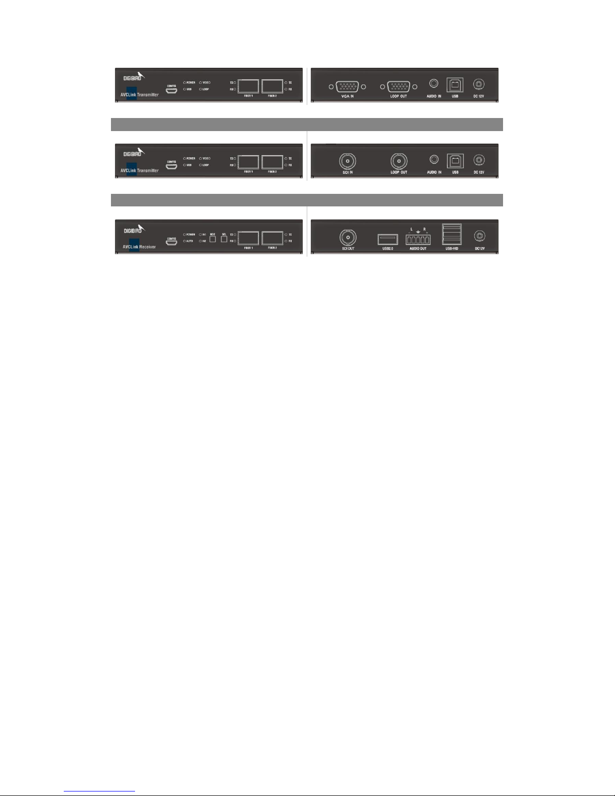
VGA Transmitter
Front Panel
Rear Panel
Introduction
10
SDI Transmitter
Front Panel
Rear Panel
SDI Receiver
Front Panel
Rear Panel
Setup
For the first time, users are recommended to test your matrix prior to install for your
project. This will assist you to avoid any cabling problems, and start to integrate with
your system more efficiently.
Setup of the matrix
1. Install the I/O cards (usually be populated well by DigiBird)
2. Connect RX and TX to the I/O ports
3. Connect keyboard, mouse, and monitor to the RX
4. Connect sources (server, DVD, computer, media player, workstation…) to the TX
5. Connect the matrix to the power supply
6. Connect the control computer to the control card via RJ45 or RS232 port.
Software
11
Software
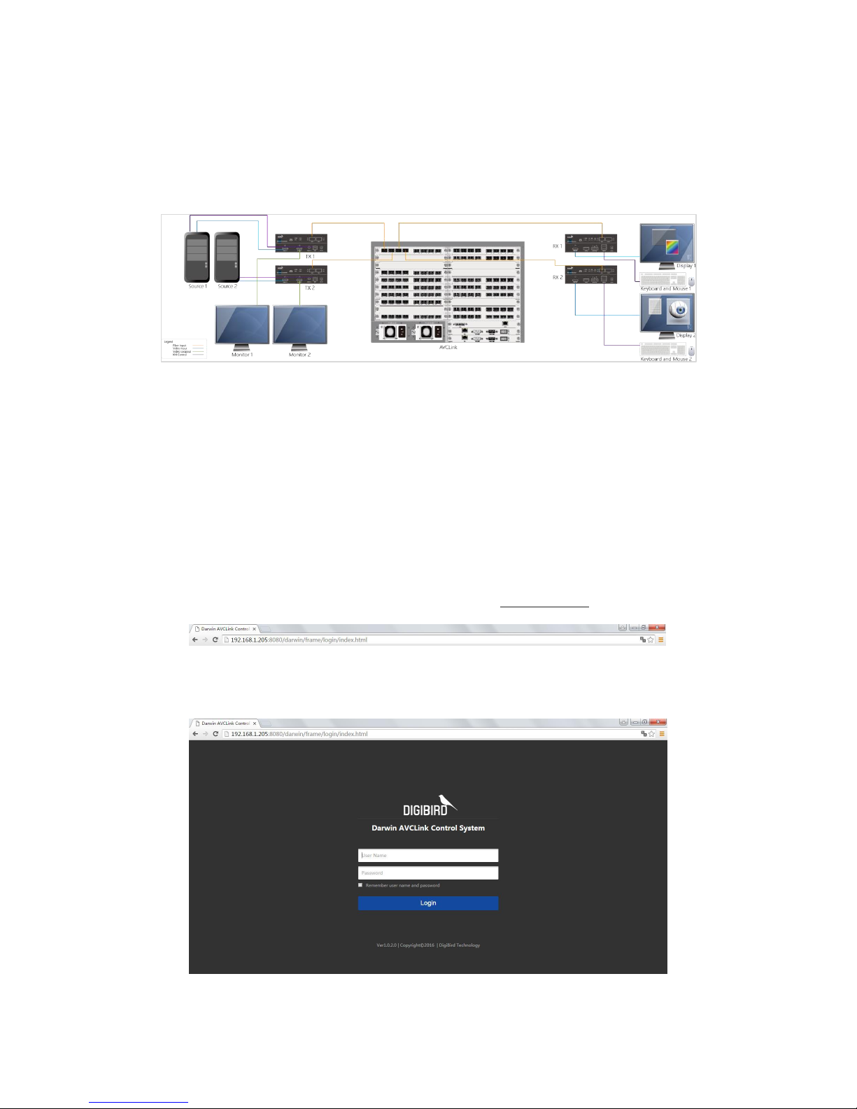
Darwin AVCLink Control System is a web-based software platform.
This manual is based on an 8U Matrix. The connection diagram is shown as below.
Login
You should open the Browser, such as chrome, to visit the Darwin AVCLink Control
System. The control computer and the Matrix must be in the same LAN network under
the same domain.
Open the Chrome and input the IP of the Matrix, then press the <Enter> key. The
default IP address of the Matrix is 192.168.1.200. You can change the IP address
through the push buttons on the front panel, see “Set IP address” for details.
You can input the user name and password in the Login page. The default user
name is “admin”, the password is “123”, which can be changed after login.
 Loading...