


AV KVM Over IP Solution
User Manual
Version 2017 V1

Contents
Contents
WELCOME 1
ABOUT THIS MANUAL 1
CAUTIONS AND NOTES 1
COPYRIGHT 1
TRADEMARKS 2
DISCLAIMER 2
SYSTEM INTRODUCTION 3
INTRODUCTION 3
DIAGRAM 3
STRUCTURE 4
TRANSMITTER 4
FRONT PANEL 4
REAR PANEL 4
RECEIVER 5
FRONT PANEL 6
REAR PANEL 6
SOFTWARE 8
LOGIN 8
DASHBOARD 9
SETTINGS 9
SWITCH 11
INPUT/ OUTPUT SWITCH 11
KVM 11
PREVIEW 12
PREVIEW ALL 13
SCENE 15
SAVE 15

Contents
PREVIEW 15
ENABLE 16
RENAME 16
DELETE 16
CONFIG 17
RENAME AND IP SETTINGS 17
STATUS 18
AUDIO 18
RESOLUTION 19
SELECTION 19
CUSTOM RESOLUTION 20
SERVER ID 21
GROUP 22
USER 24
ADD 24
AUTHORIZATION 24
EDIT 26
DELETE 26
BACKUP AND RESTORE 28
BACKUP 28
RESTORE 29
SERVER 31
UPGRADE 32
LICENSE 33
PROTOCOL 34
COMMUNICATION 34
ADDRESS 34
AVCNET THIRD-PARTY COMMANDS 34
SINGLE CHANNEL SWITCHING 34

Contents
MULTIPLE CHANNELS SWITCHING 34
ALL CHANNELS SWITCHING 35
OUTPUT STATUS 35
SAVE SCENE 36
RECALL SCENE 36
CHANGE ADDRESS 36
QUERY BASIC INFORMATION 36

Welcome
1
Welcome
About This Manual
This Manual is applicable to AVCNet (AV KVM Over IP). Thank you for choosing DigiBird,
please read this manual carefully before using the product.
All pictures in this manual are only for reference, information in this document is
subject to change without notice.
Cautions and Notes
The following symbols are used in this manual:
Notes
The necessary hints, additions and explanations to help you to
understand the content of the manual more clearly.
Cautions
This symbol indicates best practice information to show
recommended and appropriate manner to use this product
efficiently.
Warnings
The important operating instruction that should be followed to
avoid any potential damage to hardware or property, data loss, or
personal injury.
The following spellings are used in the manual:
Spelling
Description
<key>
Description of a key on the keyboard
<key + key>
Press keys simultaneously
<key, key>
Press keys successively
[Menu item]
Description of a menu item in the software
Copyright
All rights reserved by DigiBird®, © 2017.
No portion of this manual may be reproduced in any manner without the prior written
consent of DigiBird®.

Welcome
2
Trademarks
All trademark and trade names mentioned in this document are acknowledged to be
the property of their respective owners.
Disclaimer
While every precaution has been taken during preparation of this manual, the
manufacturer assumes no liability for errors or omissions. The manufacturer assumes
no liability for damages resulting from the use of the information contained herein.
The manufacturer reserves the right to change specifications, functions, or circuitry of
the product without notice.
The manufacturer cannot accept liability for damage due to misuse of the product or
due to any other circumstances outside the manufacturer’s control (whether
environmental or installation related). The manufacturer shall not be liable for any loss,
damage, or injury arising directly, indirectly, incidentally, or consequently from the use
of this product.
System Introduction
3
System Introduction
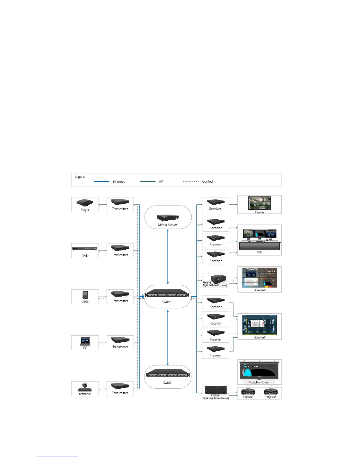
Introduction
AVCNet-H is an independent research and development product by Digibird, with high
density encoding and decoding, redundant AV networks and streams, secure content
distribution, network error resilience, critical-quality 4K video compression with
extremely low latency. AVCNet-H can distribute AV signals using standard off- the-shelf
1GbE network switches, supports a wide array of applications including Point-to-Point
Extension and complex Matrix Switching, as well as Video Wall and MultiViewer
displays.
Diagram
Structure
4
Structure
The AVCNet-H solution includes transmitter/ Tx (Input Node) and receiver/Rx (Output
Node):
Tx: DVI, HDMI, SDI, VGA and DP are available.
Rx: DVI, HDMI and SDI are available.
Note: the products are being updated time to time without notices in this manual.
Transmitter
The default IP address of the transmitter is 192.168.1.202, which can be changed via
software. To change IP, refer to Rename and IP settings.
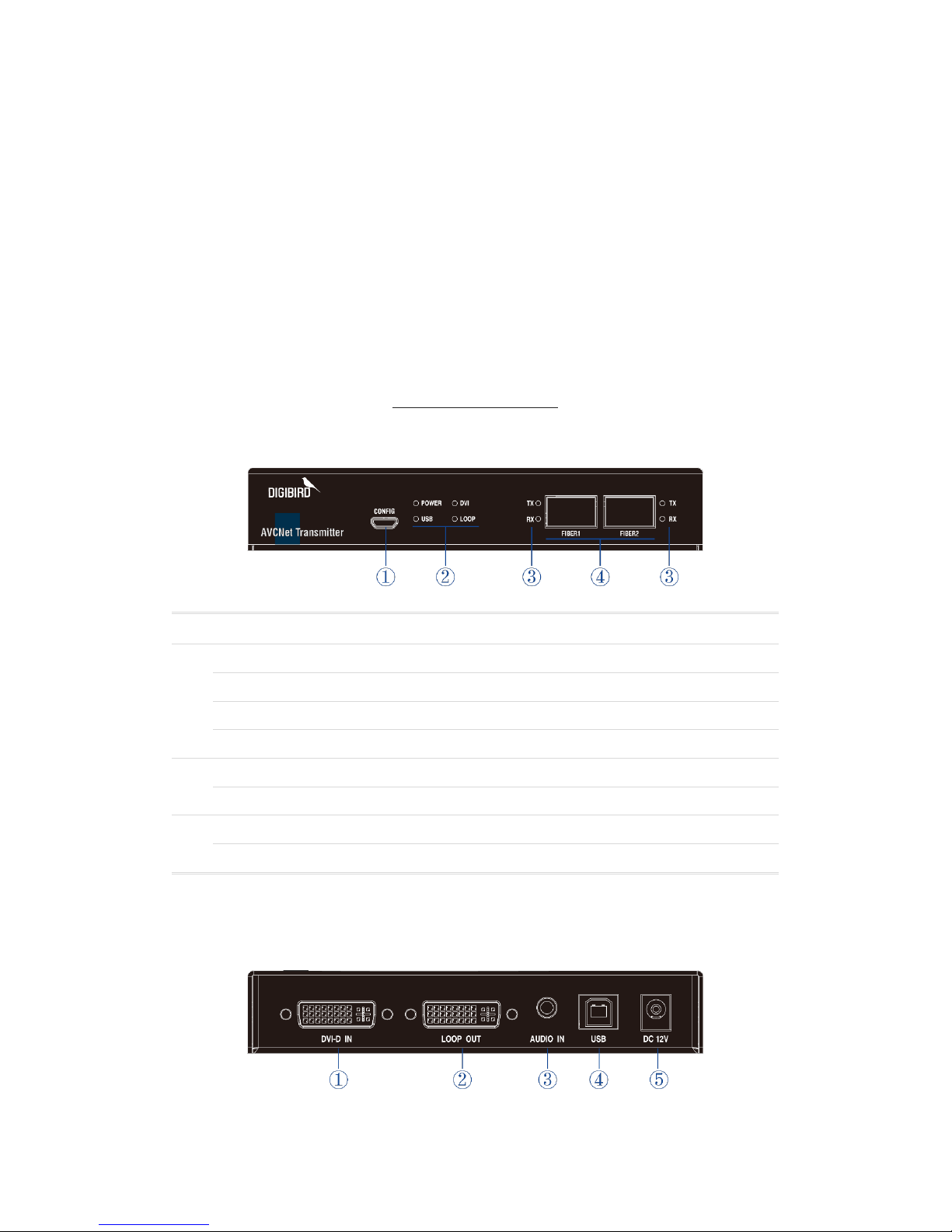
Front Panel
①
CONFIG
For firmware updates.
②
POWER
Power indicator.
DVI
Input signal indicator. Here is the example of DVI version.
USB
Control signal (KVM) indicator.
LOOP
Loop connection indicator.
③
TX
Tx indicator: illuminated when Tx node connected well.
RX
Rx indicator: illuminated when Rx node connected well.
④
FIBER1
Output port: Fiber or Cat (Fiber-Cat adapter needed) output #1.
FIBER2
Output port: Fiber or Cat (Fiber-Cat adapter needed) output #2.
Rear Panel
DVI
Structure
5
①
DVI IN
Video input port.
②
LOOP OUT
Loop Out: for local monitor.
③
AUDIO IN
Audio input port.
④
USB
USB: for KVM control.
⑤
DC 12V
Power input.
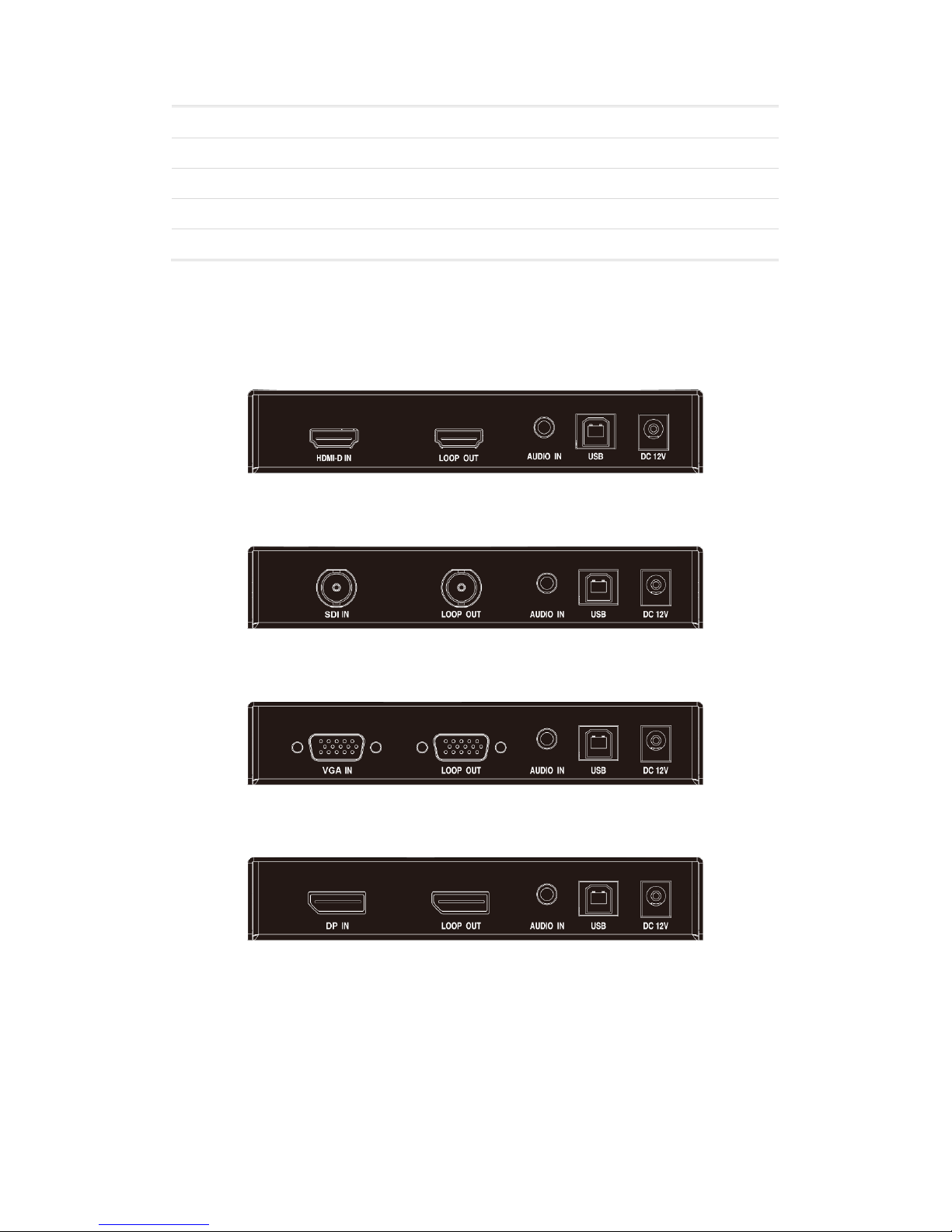
Other versions
HDMI:
SDI:
VGA:
DP:
Receiver
The default IP address of the receiver is 192.168.1.203, which can be changed via
software. To change IP, refer to Rename and Config.
Structure
6
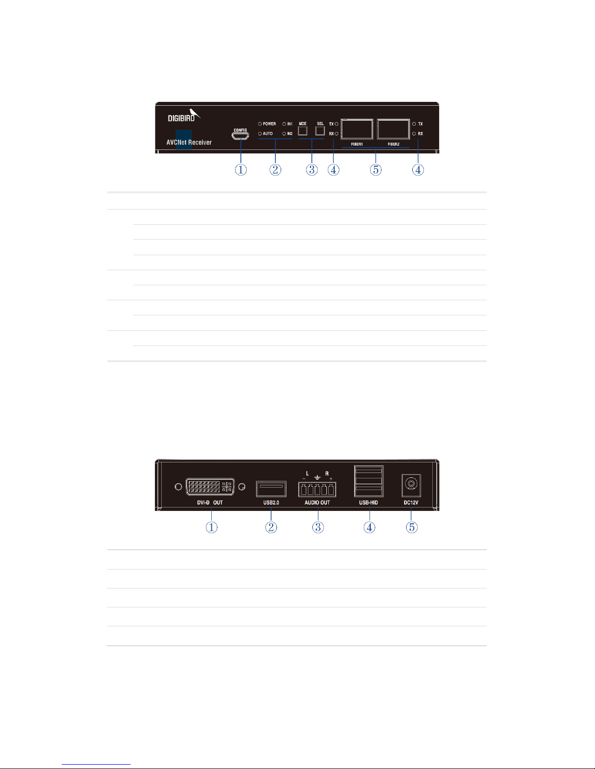
Front Panel
①
CONFIG
For firmware updates.
②
POWER
Power indicator.
AUTO
Dual-ports backup, auto select mode (1x main, 1x backup).
IN1
Input #1: illuminated when FIBER1 is main port (FIBER2 is backup).
IN2
Input #2: illuminated when FIBER2 is main port (FIBER1 is backup).
③
MDE
Mode of dual-ports backup switching. (Auto or Manual).
SEL
To select Input channel under the manual mode.
④
TX
Tx indicator: illuminated when Tx node connected well.
RX
Rx indicator: illuminated when Rx node connected well.
⑤
FIBER1
Input port: Fiber or Cat (Fiber-Cat adapter needed) input #1.
FIBER2
Input port: Fiber or Cat (Fiber-Cat adapter needed) input #2.
Note: All receivers have the same front panel.
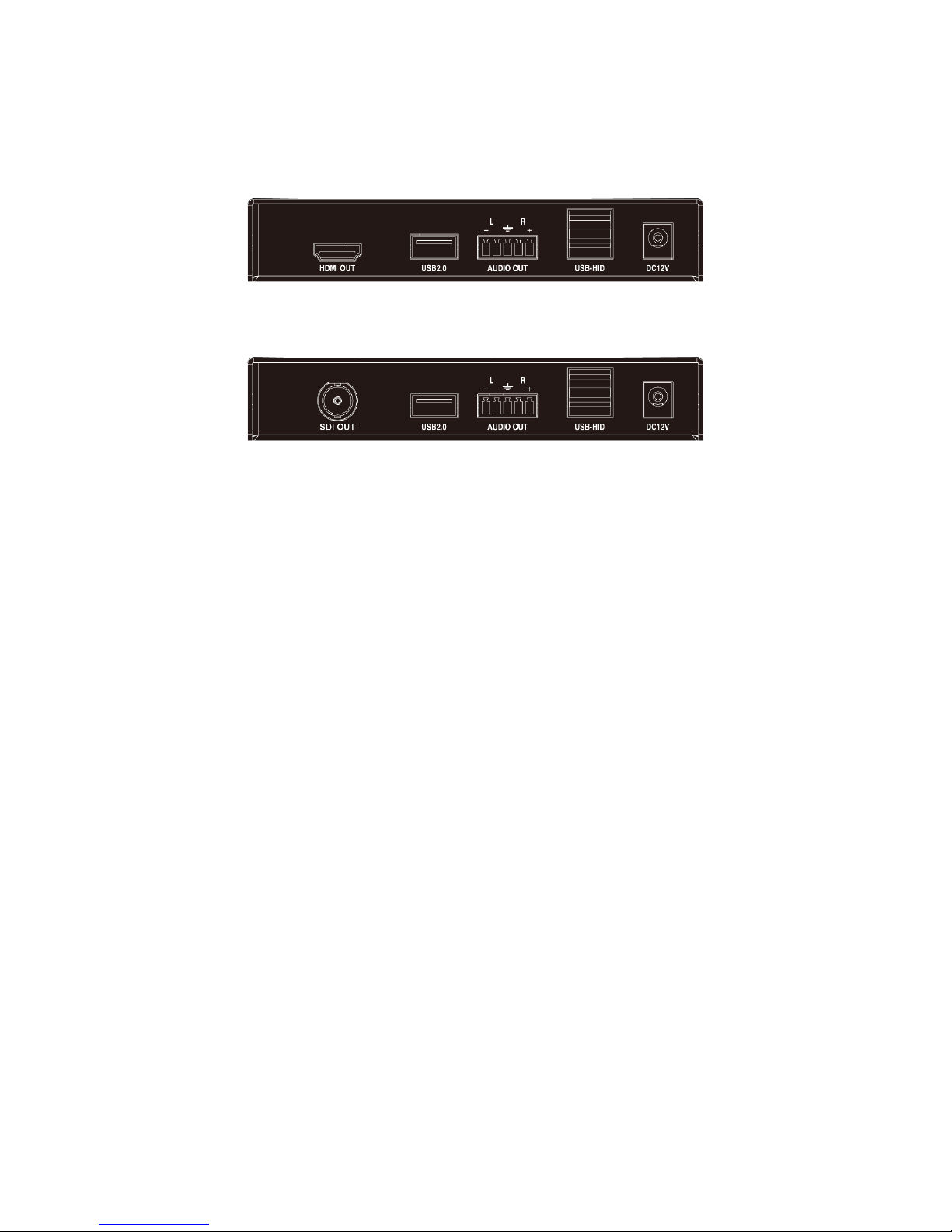
Rear Panel
DVI
①
DVI OUT
Video output port.
②
USB 2.0
Reserved port, for future use.
③
AUDIO OUT
Audio output port.
④
USB-HID
USB: for KVM control.
⑤
DC 12V
Power input.
Structure
7
Other versions
HDMI:
SDI:
Software
8
Software
It supports web-based control without application or software installed.
Web browser supported:
Browser
Version
Google Chrome
Version 49 or later
360 Chrome
8.1 or later
QQ Browser
9.5.1 or later
CM Browser
6.0 or later
UC Browser
5.7.16400.16 or later
Sogou Browser
7.0 or later
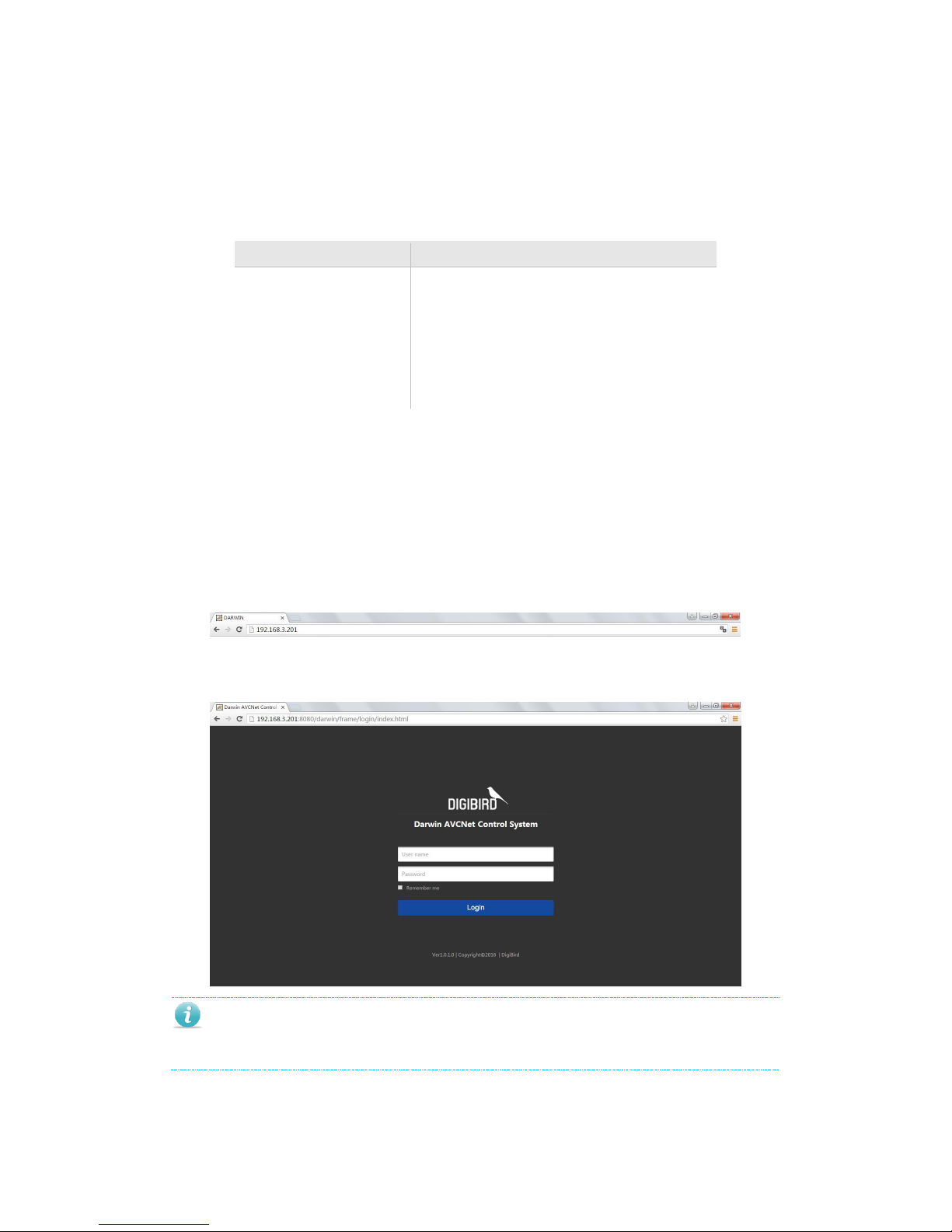
Login
The instruction is based on Google Chrome. Before using this web-based control,
please make sure the IP addresses of your PC, AVCNet-H server, Transmitters and
Receivers are under the same domain LAN network.
Type the IP address of the AVCNet-H server (for example: 192.168.3.201)
then to connect.
Use the default User Name and Password to login (User Name: admin;
Password: 123).
The IP address of the AVCNet-H server is 192.168.1.56 and 192.168.3.56. Or ask
your sales to get new one.
Software
9
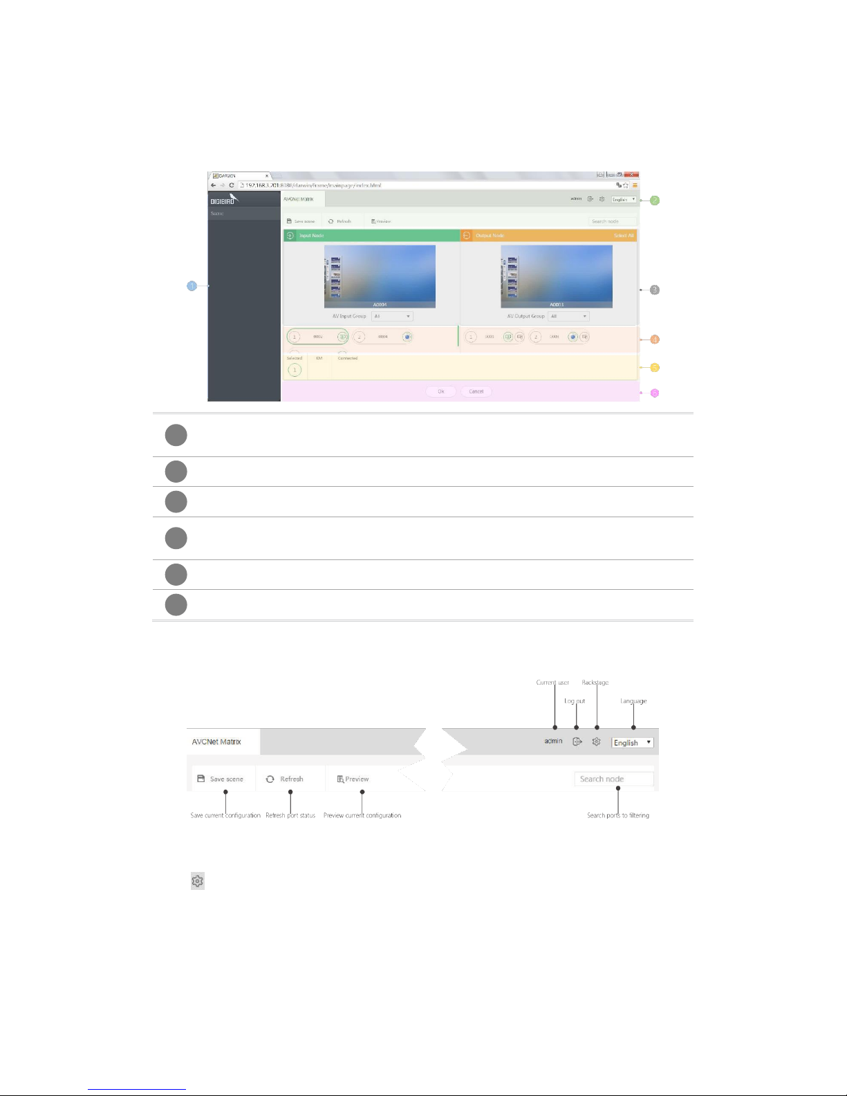
Dashboard
The Dashboard is shown as below:
Scene
The Scenes list: right click to view the menu of enable, delete, preview
and rename.
Tools
Settings, Logout, Save Scene, Refresh, Preview and Search.
Preview
Preview any input or output signal.
Input/ Output
Here list all of the auto-detected Tx/Rx nodes. Select one input and
then output(s) to distribute the signal or enable KVM control.
Distribution
Here list all relations between inputs and outputs with KVM status.
OK/ Cancel
Click OK to confirm the distribution, Cancel to abandon.
The ToolBar is shown as below:
Settings
Click to enter setting interface: Config, Group, User, Backup, Server, Upgrade,
Custom Resolution and License, etc.
1
2
3 4 5
6

Software
10

Switch
11
Switch
Input/ Output Switch
To switch one input signal to one or more outputs.
Select one Input Node.
Select output(s):
Click Cancel to abandon.
Click OK to confirm.
KVM
Select one input node, the relevant output nodes will displayed at the right
side.

Switch
12
Click the icon to select enable KVM and the icon will turn to be . The
KVM channel number will display in the below KM (Keyboard & Mouse) list.
Click OK to confirm or Cancel to abandon.
Preview
To preview any input or output signal.
Select any input or output node.
Click the icon and turn to be on the selected input node:

Switch
13
Preview the output:
Preview all
Click Preview button on the toolbar, the user is able to check all inputs/ outputs
relations.

Switch
14

Scene
15
Scene
The Scene means preset or scenario, which contains all distributions between input
nodes and output nodes, can be recalled anytime.
Save
Click Save Scene:
Input a name for the scene:
Preview
The user is able to preview the scene before recalling.

Scene
16
Enable
Right click on the scene list and enable to recall the scene.
Rename
The user is able to rename the scene at any time.
Delete
The user is able to delete the scene at any time.

Cinfig
17
Config
The config includes input/output settings, audio channel selection, I/O node name and
resolution settings.
Rename and IP settings
Select one node, click the icon to rename or change the IP settings.
▼
Click [OK] to complete as below:

Cinfig
18
Status
Click the icon on the selected input node or on the selected output node
to check the connection status.
Audio
It supports embedded audio or separated audio channels selection (for HDMI or SDI
version).
The user is able to use the batch operation button to select audio channels for more
nodes at one time.

Cinfig
19
Resolution
Selection
Click the resolution button to select resolution for the output node:
Inherit: to set the same resolution with that of input; Custom: to set a
confirmed resolution.

Cinfig
20
The user is able to select from the dropdown list or setup customized one.
Custom resolution
Enter the System Resolution settings to setup custom resolution:
The user is able to add new resolution.

Cinfig
21
The user added resolution can be edited or deleted but the default one not
allowed to edit or delete.
Server ID
Server ID: to manage the input/output nodes controlled under the current server.
Un-checked: means the node(s) is (are) not under this server management.
Check the to be then the user is able to manage it.

Group
22
Group
To group the input/output nodes.
Select input node to add a group from the dropdown list.
Input the group name and click OK.
Select input nodes to add to the group.

Group
23
Go back to the dashboard, the user is able to show the group of nodes.
To add group for the output nodes by the same operation:

User
24
User
To manage multiple users and dispatch different authorization.
Add
Click to new a user.
Fill in the information for the new user:
Authorization
To setup different user levels with different authorization.
1. Click the to setup.
Input Node authorities
Enable: the user is able to manage the input node.
Disable: the user is NOT able to manage the input node.
Inherit: is default settings.

User
25
▼
Menu authorities
Enable: the user is able to manage the menu.
Disable: the user is NOT able to manage the menu.
Inherit: is default settings.
▼
Inherit: means the authorities of the current level is the same as the upper level, for
example when the check enable for settings and inherit for config, then the authorities of

User
26
config is enabled; when check disable for settings then that of config is disable. The inherit
level will follow its upper level settings.
2. Re-login with the added user account, the software interface has been changed.
Admin: with all authorities
User: with limited authorities
Edit
Select one user account and edit the info:
Delete
Select one user account and delete:

User
27

Backup and Restore
28
Backup and Restore
Backup
To backup the configuration for future restore.
Click Backup data button to backup all configuration data of
hardware and software.
Click Download button to download the data to your PC.

Backup and Restore
29
The AVCNet-H is able to backup data every day automatically and keep for 7 net days
one time. The data on the 1st day will be displaced on the 8th day.
Restore
1. Restore data from hardware
Click the restore to recovery the data that is saved in the hardware.
2. Restore data from PC
Click Upload & restore to select, upload and recovery the data
saved in your PC.

Backup and Restore
30
3. Recovering
It may take 2 minutes to complete the restore.

Server
31
Server
The server is used to configure, manage, control and preview the input and output
nodes.
The user is recommended to change this setting for sever when install your project
under DigiBird technical supports help.

Upgrade
32
Upgrade
Select and upload the upgrade file to complete. The user is able to request the latest
firmware from your sales or contact our team at sales@digibirdtech.com.
Do NOT power off when do the upgrading.

Lisense
33
License
For renew your license, please contact your sales or contact our team:
sales@digibirdtech.com.

Protocol
34
Protocol
Communication
TCP or UDP, port 5000.
Address
Each command line contains one device address “ADDR”, default is 0.
When ADDR is default 0: the device is to receive all commands.
When the command sender (the device to send command out) is with ADDR 0, the
receiver device must receive this command no matter what ADDR this device has.
When the command sender’s ADDR is not 0 and the receiver device’s ADDR is not 0,
they have to match the address then to receive command.
Send Command (INFO,0), to check the device’s ADDR.
({"ctrlAddr":"2","ip":"192.168.1.201/192.168.3.201",inputNum":10,"inputIndex":10,"out
putNum":20,"outputIndex":22,"deviceName":"avcnet"}),
"ctrlAddr":"2": means the address is 2.
AVCNet third-party commands
Format:
(command name,address,data,data,…) The address is must, if it is 0, means the
current device.
Single channel switching
Format: (SWCH,ADDR,V/C,IN-OUT)
V/C: V means to switch video, C means to switch control signal and the video together.
Response: Correct (SWCH,ADDR,OK); Error (SWCH,ADDR,Err)
Note: this command is used to switch one input signal to another output channel.
The address is optional.
For example: to switch video of input 1/device 1 to output 2
Command: (SWCH,1,V,1,2)
Multiple channels switching
Format: (SWCM,ADDR,IN-OUT/OUT/OUT-C)
If not switch the KVM control signal, C value is 0 and C must be one of the output
channels.
Response: Correct (SWCH,ADDR,OK); Error (SWCH,ADDR,Err)

Protocol
35
Note: this command is used to switch multiple channels, maximum 32x channels,
address is optional.
For example #1: to switch input 1/device 1 to outputs 2, 3 and 4 with KVM control
switched to output 3.
Command: (SWCM,1,1-2/3/4-3)
For example #2: to switch input 1/ device 1 to output 3 without KVM control
switched.
Command: (SWCM,1,1-3-0)
This command may causes switching closed, for example when change input 1
switched to 1 and 2 from 1, 2, 3 and 4, then the switching to 3 and 4 will be closed.
All channels switching
Format: (SWCA,ADDR,V,IN)
Response: correct (SWCA,ADDR,OK); Error (SWCA,ADDR,Err)
Note: this command is used to switch one input to all outputs, address is optional.
For example, to switch input 2/ device 1 to all output channels:
Command: (SWCA,1,V,2)
Output status
(1) Single channel status
Format: (GETV/GETC,ADDR,OUT)
GETV: to get switching status of audio and video.
GETC: to get switching status of KVM control signal.
Response: Correct to response status; Error (GETV,ADDR,Err)
Note: this command is used to query the switching status of single channel.
For example, to query status of the output 1/ device 1
Command: (GETV,1,1)
Response: (GETV,1,2)
(2) Multiple channels status
Format: (GETV/GETC,ADDR,OUT,OUT….)
Response: Correct to response status; Error (GETV,ADDR,Err)
Note: this command is used to query all output channels status, maximum
32x channels per command line, address is optional.
For example, to query status of the output 1, 2 and 3/ device 1
Command: (GETV,1,1,2,3)
Response: (GETV,1,7,8,9)

Protocol
36
Save scene
Format: (SAVE,ADDR,Num)
Response: Correct (SAVE,ADDR,OK); Error (SAVE,ADDR,Err)
Note: this command is used to save the current distribution status to some scene.
Num: the number of scene begins with 1.
For example, to save the distribution status of device 1 to scene 3.
Command: (SAVE,1,3)
Recall scene
Format: (CALL,ADDR,Num)
Response: Correct (CALL,ADDR,OK); Error (CALL,ADDR,Err)
Note: this command is used to recall some scene and to replace the current
distribution status.
For example, to recall scene 3/ device 1
Command: (CALL,1,3)
Change address
Format: (ADDR,ADDR,newADDR)
Response: Correct (ADDR,ADDR,OK); Error (ADDR,ADDR,Err)
Note: this command is used to change the address of device. The response is still
the original address.
For example, change device 1 to device 2.
Command: (ADDR,1,2)
Query basic information
Format: (INFO,ADDR)
Response: Correct
({"ctrlAddr":"2","ip":"192.168.1.201/192.168.3.201",inputNum":10,"inputIndex":10,
"outputNum":20,"outputIndex":22,"deviceName":"avcnet"});
Error (INFO,AddR,Err)
For example, to query the current device info
Command: (INFO,0)

DigiBird Technology Co., Ltd
-------------------------------
www.digibirdtech.com
sales@digibirdtech.com
 Loading...