

Digibell Vandal Resistant System, 801PS, 801S, BS-LX, 801 Installation & Operation Manual
...
Bell System (Telephones) Ltd
Digibell
Digital Audio Door Entry System
Vandal Resistant
Installation & Operation Guide
PD-169 Issue 3B

Digibell Vandal Resistant System
PD-169 Issue 3B Installation Guide Page 2 of 56

Digibell Vandal Resistant System
PD-169 Issue 3B Installation Guide Page 3 of 56
Table of Contents
Table of Contents ........................................................................................ 3
Introduction ................................................................................................. 5
Features ...................................................................................................................... 5
System Operation ....................................................................................... 6
Entrance Panel ............................................................................................................ 6
Call sequence.............................................................................................................. 6
Phone Controls............................................................................................................ 7
Design Considerations ............................................................................... 8
Entrance panels .......................................................................................................... 8
Control units ................................................................................................................ 9
Power Supplies ........................................................................................................... 9
Compatible Phones ................................................................................................... 10
Privacy of Speech ..................................................................................................... 10
Extension sounders and flashing strobe .................................................................... 10
Lock Releases ........................................................................................................... 11
Exit button (Egress) ................................................................................................... 11
Fireman’s switch, Break glass or Emergency exit button .......................................... 11
Trades Facility ........................................................................................................... 11
Coded Access Facility ............................................................................................... 11
Multiple Entrances ..................................................................................................... 11
DDA Functionality ...................................................................................................... 11
Gate and Block Systems ........................................................................................... 11
Cable requirements................................................................................... 12
Cable Distances ........................................................................................................ 13
Cable overviews ........................................................................................ 14
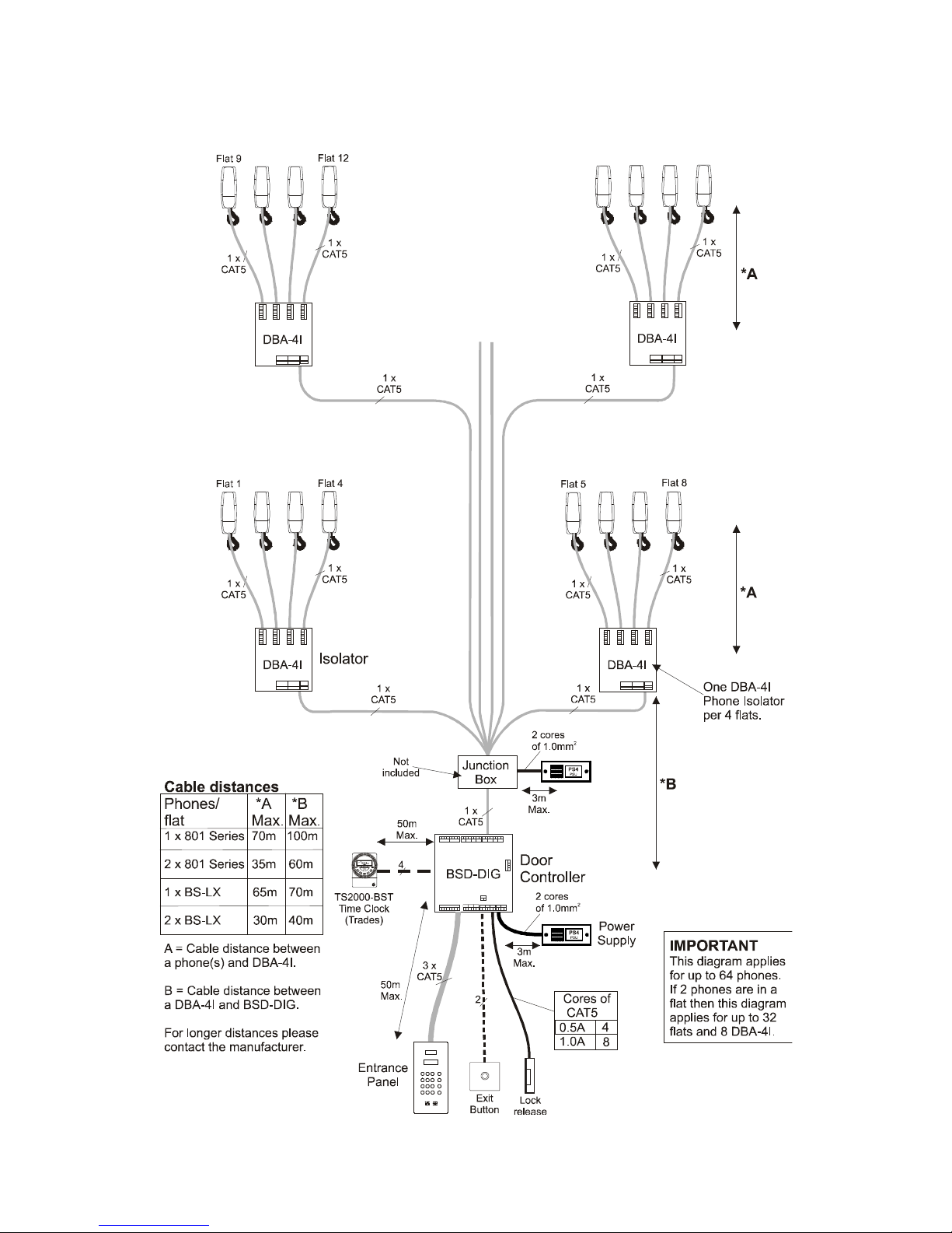
Diagram 1 – Full Isolation, 1 entrance up to 32 phones ............................................ 15
Diagram 2 - Full isolation, 1 entrance 33 to 64 phones ............................................. 16
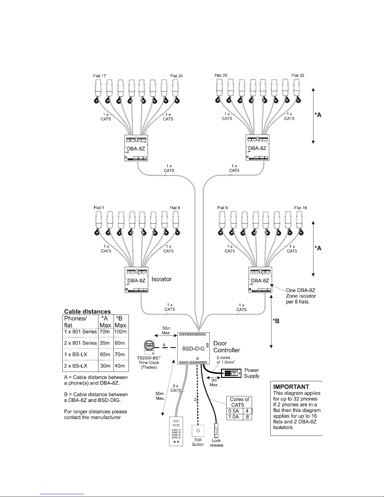
Diagram 3 - Zone isolation, 1 entrance up to 32 phones ........................................... 17
Diagram 4 - Zone isolation, 1 entrance 33 to 64 phones ........................................... 18
Diagram 5 - System / Entrance interconnections ...................................................... 19
Installation & Commissioning Guide ...................................................... 20
Installation ................................................................................................................. 20

Digibell Vandal Resistant System
PD-169 Issue 3B Installation Guide Page 4 of 56
Commissioning .......................................................................................................... 20
Entrance Panel .......................................................................................................... 20
Electric Door Release ................................................................................................ 21
Entry and exit considerations .................................................................................... 21
Exit Button input ........................................................................................................ 21
Door Open Switch ..................................................................................................... 21
Time Clock Sharing ................................................................................................... 21
Entrance Panel Programming ................................................................................... 22
DBA-4I 4 Way Phone Isolator.................................................................................... 27
DBA-8Z 8 Way Zone isolator ..................................................................................... 32
Phone settings........................................................................................................... 38
Troubleshooting ........................................................................................ 40
Common Faults ......................................................................................................... 40
Lock Release Problems ............................................................................................ 40
Entrance Panel Display Problems ............................................................................. 41
Telephone Ring Problems ......................................................................................... 41
Speech Problems ...................................................................................................... 42
Specifications ............................................................................................ 43
Wiring diagrams ........................................................................................ 45
Diagram 6 – Entrance Connections ........................................................................... 46
Diagram 7 – Phone Connections (Zone Isolation) ..................................................... 47
Diagram 8 – Phone connections (Full Isolation) ........................................................ 48
Diagram 9 – Isolator Interconnections (single PSU required) .................................... 49
Diagram 10 – Isolator interconnections (separate Power supply) ............................. 50
Diagram 11 – Entrance interconnections (BSD-DIG) ................................................ 51
Diagram 12 – Optional Features ............................................................................... 52
Diagram 13 – Combined System Connections .......................................................... 53
Diagram 14 – ACT Proximity Fob system interconnections ...................................... 54
Safety Information and Declarations ...................................................... 55

Digibell Vandal Resistant System
PD-169 Issue 3B Installation Guide Page 5 of 56
Introduction
The Digibell digital door entry telephone system is designed primarily for large blocks of flats
in the private or public housing sector, where reliability and serviceability are of prime
importance.
The Digibell system offers two levels of cable isolation: ‘Full Isolation’ (between individual
dwellings) for buildings where vandalism by residents may be high and ‘Zonal Isolation’
(between floors or zones) for a more cost effective system.
The use of a Digital entrance panel (with keypad and display) affords a more compact
solution when compared with a standard door entry panel (i.e. one button per flat) which may
be impractical due to its size.
Features
• Capacity for over 400 flats and 16 entrances per block
• Large 4-digit LED display with informative messages, e.g. ‘CALL’, ’TALK’, ‘ OPEN’
• Alphanumeric flat numbers, e.g. 20A, B102
• High quality full-duplex speech.
• Ring and lock reassurance tones
• 4-Digit coded entry facility for resident access
• Optional Proximity Access
• Tradesman’s access (time restricted and/or with access code)
• Dedicated Porter/Reception button.
• Compliance with Disability Discrimination Act (DDA) (selected panels)
• Choice of Phone isolation or Zone isolation depending on requirements
• 12V DC System with optional battery backup
• Control equipment optionally supplied in lockable Steel cabinets for greater security
• Uses standard CAT5 cable.
• Compatible with model 801 & BS-LX telephones
Digibell Vandal Resistant System
PD-169 Issue 3B Installation Guide Page 6 of 56
System Operation
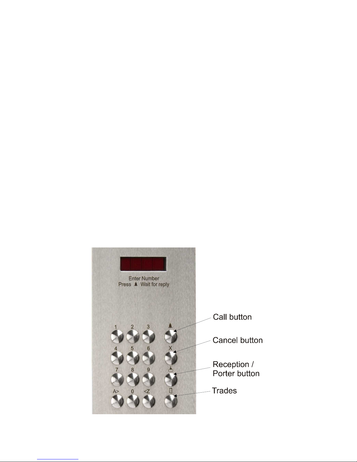
Entrance Panel
0-9, A>, <Z
Enter a flat number up to 4 digits.
A>
& <Z
are used to enter the
alphabetic characters (A-Z); Press A> to enter A; subsequent
presses advance through the alphabet, while <Z can be used to step
backwards.
For example to enter flat number “C21”, press A> A> A> 2 1
Call
Press to call a flat once the correct number is displayed.
Cancel
Cancels the current entry leaving a blank display.
Reception
Press to call the Porter / Reception / Concierge
Trades
Press to gain direct access during restricted hours or using an
access code.
Call sequence
The caller firstly approaches the entrance panel and enters the required flat number followed
by the call button. This causes the phone to ring in the selected flat. The phone will continue
to ring for typically 30 seconds if not answered or until the resident responds by picking up
the handset. The call may be terminated by replacing the handset or more usually by
pressing the lock/key button to allow the visitor access through the entrance.

Digibell Vandal Resistant System
PD-169 Issue 3B Installation Guide Page 7 of 56
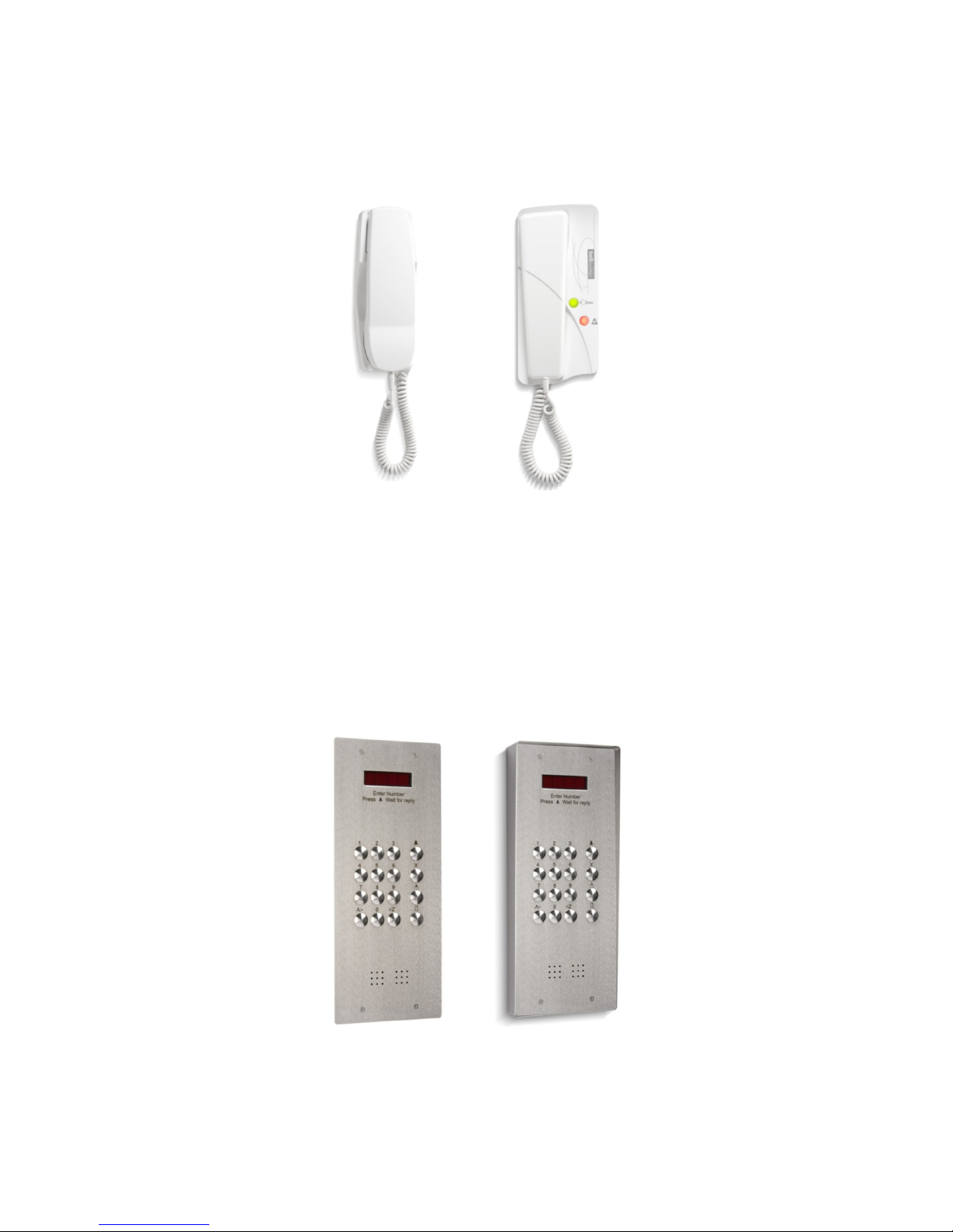
Phone Controls
All phones have 2-way speech and a lock button to release the door. For security, phones
must be called first and taken off the hook before the lock release button will function; a stuck
lock button will be ignored.
Ringer Mute
With some models of telephone (801PS, 801S & BS-LX) the resident can mute the ringing
sound of their phone when they do not wish to be disturbed.
Model 801PS/801S phones: Sliding the switch on the right hand side to the ON position
enables the ringer whilst the OFF position disables (mutes) the ringer.
Model BS-LX phone: Ringer mute is activated by pressing the mute button on the phone,
which illuminates red as a reminder. Pressing the mute button a second time will disengage
the mute function. During installation it is possible to set a time limit for the mute function in
various values from 2 minutes up to 10 hours or indefinitely. When this time period has
elapsed the mute function will automatically disengage (See ‘Phone settings’ in the reference
section). The mute feature stops the audible ring, but the red mute light will still flash to
indicate a call and all other functions work normally. Ringer mute will continue for the preset
time even if a call is answered.
Door Status Indication – BS-LX Only
The green lamp on the phone illuminates to warn the resident that a door has been left open
following a call. This feature requires a door monitor contact to be fitted.
Digibell Vandal Resistant System
PD-169 Issue 3B Installation Guide Page 8 of 56
Design Considerations
Please read in conjunction with the cable overview drawings starting on page 14 to determine
the equipment required for your system.
Entrance panels
All entrance panels are Stainless Steel Vandal Resistant and have a 4-digit red LED dotmatrix display mounted behind a protective LEXAN window. Both flush and surface types are
available. Surface entrance panels can also be supplied fitted to Stainless Steel posts of
varying heights for vehicle entrances or where it is impractical to fit directly on a building. The
‘LCP’ version is a flush Stainless Steel panel with welded back-box and laser cut bezel for
enhanced vandal resistance. Security screws are supplied with all entrance panel.
The entrance panels feature reassurance tones for lock and call operations and a trade’s
button/coded access facility (which requires a TS2000-BST time clock).
Part No.
Description
DBAP-VR Flush Stainless Steel digital entrance panel
DBAP-VRS Surface/Flush Stainless Steel digital entrance panel
DBAP-LCP Flush Stainless Steel digital entrance panel with welded backbox and
laser cut front bezel
DBAP-DDA Flush Stainless Steel digital DDA* entrance panel
DBAP-DDA-S Surface Stainless Steel digital DDA* entrance panel
Stainless Steel Posts for surface panels DBAP-VRS & DBAP-DDA-S (not included):
CHP1 Car height post, 1200mm
PHP1 Pedestrian height post, 1600mm
DHP1 Dual height post, pedestrian and car, 1200mm & 1600mm
DHP2 Dual height post, HGV and car, 1200mm & 2000mm
*DDA entrance panels include yellow halo buttons and have a raised pip on the 5 button.
Various other DDA options are available on request.
Proximity
Fob readers can be integrated into the entrance panels. A standard 40mm square cut-out is
used. To specify our standard Paxton Fob reader add the following to each entrance:
1 x PROX/CO Proximity reader cut-out
1 x PAX1 Proximity reader
Bell system can also supply Proximity/Fob access systems with added features such as PC
management, audit trails, on or offsite management.
Digibell Vandal Resistant System
PD-169 Issue 3B Installation Guide Page 9 of 56
Other third party readers can be accommodated depending on the size and fitting required.
Control units
All control equipment must be placed in a protected indoor environment or enclosure.
Part No.
Description
BSD-DIG Digital door controller (1 required per entrance panel)
DBA-4I 4 Way phone isolator (1 required every 4 flats)
DBA-8Z 8 Way zone isolator (1 required every 8 flats)
TS2000-BST Time clock with BST correction (1 required per system for trades
facility)
Various options are available when the control equipment is placed in one of our Steel
lockable cabinets; please contact your sales representative for advice.
Power Supplies
Please refer to the safety information at the end of this literature
Part No.
Description
PS4 12V DC 4A Regulated power supply
840 12V DC 3A with battery backup (requires a BAT01 12V 7AH battery)
BAT01 12V 7AH Lead acid battery
Power Supply Requirements (refer to overview drawings starting page 14)
1 x PS4 or 840
1 entrance + 32 phones
2 entrances (2 x BSD-DIG)
64 Phones:
8
4
16
8
DBA-8Z Isolators
DBA-8Z Isolators
DBA-4I Isolators
DBA-4I Isolators
with
with
with
with
1 phone in each flat
2 phones in each flat
1 phone in each flat
2 phones in each flat
Digibell Vandal Resistant System
PD-169 Issue 3B Installation Guide Page 10 of 56
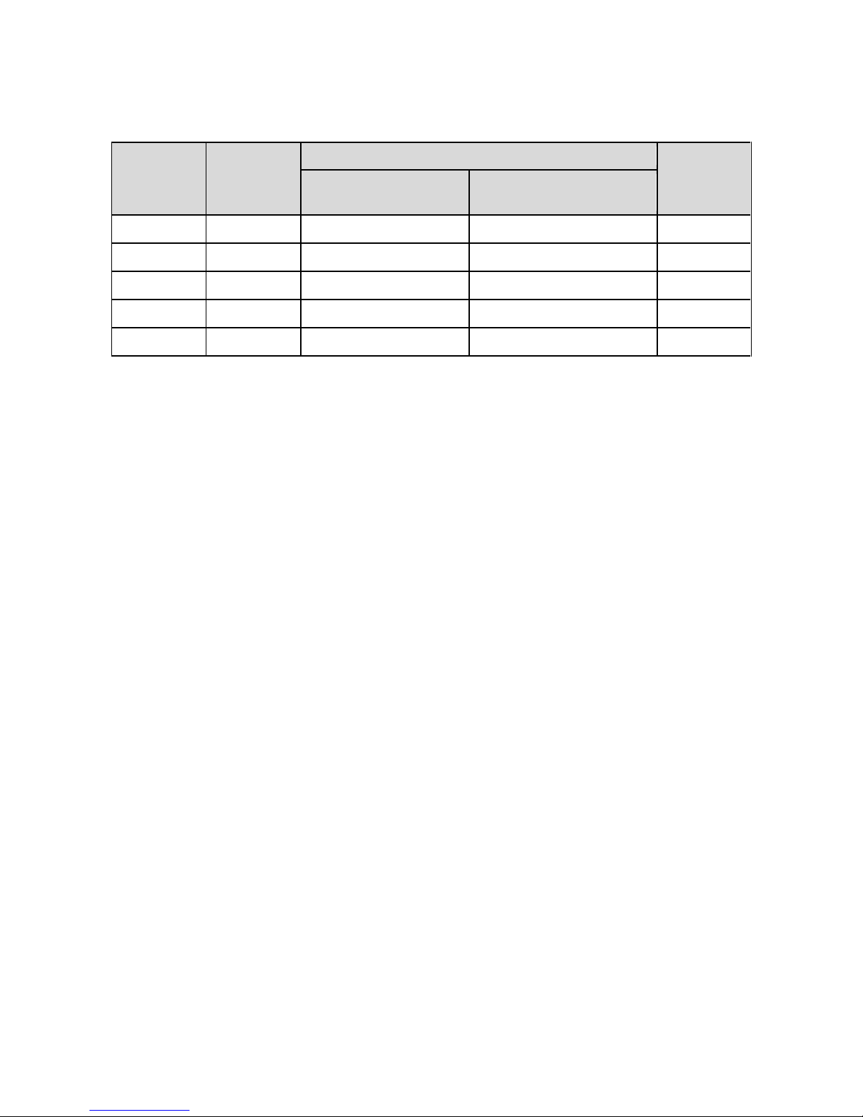
Compatible Phones
Model
Priva
cy of
Speech
Buzzer mute
Door
open
indicator
Slide
switch
(
on/off
) Button with indicator;
adjustable mute time
801
x x x x
801S
x √ x x
801P
√ x x x
801PS
√ √ x x
BS-LX
√
x √
√
Phones connected to a DBA-4I Phone Isolator have privacy of speech inherent in the design
therefore models 801P and 801PS should not be used. All phones connected to the same
DBA-8Z Isolator must be the same model (a mixture of desk or wall mounting is allowed).
As standard a maximum of two phones are allowed in each flat. Contact your distributor if
more are required.
The phones specified above are wall mounting. For a desk-mount model, add ‘–DESK’ to any
of the 801 phone series part numbers.
Phones can be supplied with a hearing aid induction loop fitted: add ‘-IDL’ to the part number.
Privacy of Speech
Once a call has been initiated from an entrance panel only the phones which are ringing may
answer the call. The conversation cannot be overheard by another phone except an
extension phone in the same flat (i.e. one which had also been ringing). This feature is
available on systems with Full Isolation (all phone models) and on Zonal Isolation (801P,
801PS and BS-LX models only).
Extension sounders and flashing strobe
The RT27 extension sounder can be fitted instead of a 2nd phone and has a similar volume
level and sound to the 801 series phones.
The SG1 sound generator has an adjustable volume level and 8 different tones. The volume
is louder than an RT27, but requires an extra 12V DC power supply such as a model 340C.
This power supply should be fitted close to the SG1. There is a maximum of 3 units per flat.
A FB31 flashing beacon is also available for the hard of hearing. The device requires an extra
power supply such as the 340C which should be a short distance from the FB31. There is a
maximum of 3 units per flat.
Note it is not possible to have a DBA-4I or DBA-8Z Isolator phone output connected to just
extension sounders or a strobe, a phone must be present.

Digibell Vandal Resistant System
PD-169 Issue 3B Installation Guide Page 11 of 56
Lock Releases
The BSD-DIG door controller supports both fail-secure and fail-safe lock releases including
magnetic locks of up to 1A rating at 12V DC. Suitable transient voltage protection must be
fitted across any Maglock or lock release (Some Maglocks have protection inbuilt).
If a voltage free output is required for an automatic gate trigger, or connection to another
system, an additional 12V DC relay will be needed, e.g. model 89.
Whether the lock is released from the phone, the Trades button or Exit button the door will
unlock for a pre-programmed time (adjustable 1-99 seconds, default 3 seconds).
Various lock releases can be supplied for standard timber frame doors, please contact your
sales representative for advice.
Exit button (Egress)
An input is provided for an exit button, which can be installed on the inside of the door and
allow residents to exit freely. Momentary operation of this button will operate the lock release
for the programmed lock time. The button must be of the ‘push to make’ type.
Fireman’s switch, Break glass or Emergency exit button
These should all be wired directly in series with the Fail safe lock release or Maglock itself, so
that they break the connection when operated.
Trades Facility
The Trades button allows access to the postman or other authorized tradesmen usually
during restricted hours and, if so programmed, after entering a four digit access code
(requires a TS2000-BST time clock).
Coded Access Facility
The system can allow access with two 4 digit codes. Normally 1 is allocated for use with the
Trades facility and the other is used for general resident or caretaker access. The Trades
button is used to initiate entry of either code.
Multiple Entrances
The Digibell system allows multiple entrances to be catered for (up to a maximum of 16) with
the addition of a door controller and entrance panel for each entrance and additional power
supplies as necessary.
DDA Functionality
There are a range of options for entrance panels to help meet the requirements of the
Disability Discrimination Act (DDA), including Braille characters and hearing aid induction
loop. Contact your sales representative for further details.
Gate and Block Systems
Sites with 2 or more blocks sharing a vehicle or pedestrian gate are catered for with a BSSW
Gate/Block isolator (1 per block). The blocks can then work independently but will receive
calls from the shared entrances/gates. Please refer to ‘Digibell Gate and Block Supplement.

Digibell Vandal Resistant System
PD-169 Issue 3B Installation Guide Page 12 of 56
Cable requirements
All system wiring must be carried out using CAT5 data cable except were otherwise
specified. CAT5 is necessary as it has a guaranteed noise performance and meets the
requirements of the EMC directive.
Flex or ‘Twin and Earth’ (1.0mm2 min.) is specified for 12V power connections etc ( see
table below).
Bell System will be unable to offer any warranty or support for systems installed using
incorrect cables.
Cat5 Cable Specification
Cat5 is our short reference for EIA standard UTP Category 5 Unshielded Twisted Pair data
cable. This is a standard 0.5mm diameter 0.2mm² solid core twisted pair cable having 4
pairs (8–cores) and no shield. The cores are in pairs where Blue and ‘Blue with a White
stripe’ are twisted together as the first pair. The other three pairs are similar with main
colours Orange, Green and Brown.
• Also available and acceptable are:
UTP Category 5e (Cat5e)
UTP Category 6 (CAT6)
UTP Category 6e (CAT6e)
The exact cable can be chosen from the above on cost and availability grounds.
• UTP CAT5 Patch cable is normally more expensive, but is suitable.
• STP (Shielded Twisted Pair) cables are not recommended.
NOTE: Cat5 cable is easily identifiable as the specification is printed on the sheath.
Digibell Vandal Resistant System
PD-169 Issue 3B Installation Guide Page 13 of 56
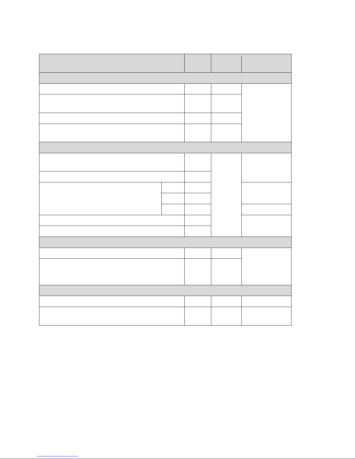
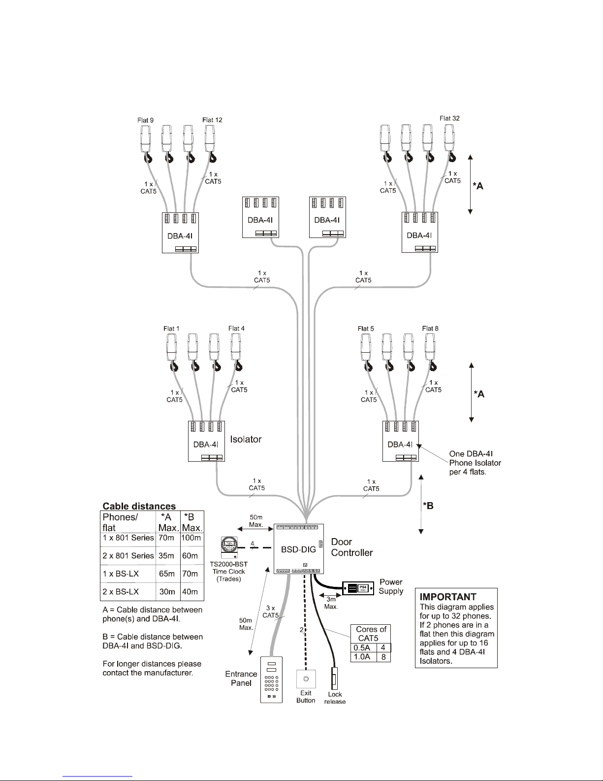
Cable Distances
Connection
No.
of
cores
Cable
length
Core Type
Phone connections
DBA-4I/8Z to 1 x 801, 801S or 801PS phone 5 70m
CAT5
DBA-4I/8Z to 2 x 801, 801S or 801PS phones
(in the same dwelling)
5 35m
DBA-4I/8Z to 1 x BS-LX phone 7 65m
DBA-4I/8Z to 2 x BS-LX phones
( in the same dwelling)
7 30m
Entrance to
Control equipment (BSD
-
DIG D
oor controller
)
Entrance Panel DBAP-VR
Also –VR(S), -LCP, -DDA(S)
18
50m
CAT5
PAX1 Fob reader (extra to any entrance panel) +3
Lock release 0.5A 4
CAT5
1A 8
1A 2 1.0mm2
Exit button 2
CAT5
Door monitor contact / switch 2
System Interconnections
DBA-4I / DBA-8Z to Power Supply/BSD-DIG 8 **2
CAT5
BSD-DIG to BSD-DIG
+ Trades facility (optional)
6
+1
**1
Misc
Power Supply to BSD-DIG 2 3m 1.0mm2
TS2000-BST Time clock to BSD-DIG Door
controller (optional)
4 50m CAT5
**1 There is no restriction on this distance, except, the maximum overall cable distance
between the furthest 2 points (entrance panel to phone via the control equipment) on
the system must not exceed 300m.
**2 Refer to the cable overview diagrams 1, 2, 3, 4 or 5
For larger cable distances please contact the manufacturer.
Digibell Vandal Resistant System
PD-169 Issue 3B Installation Guide Page 14 of 56
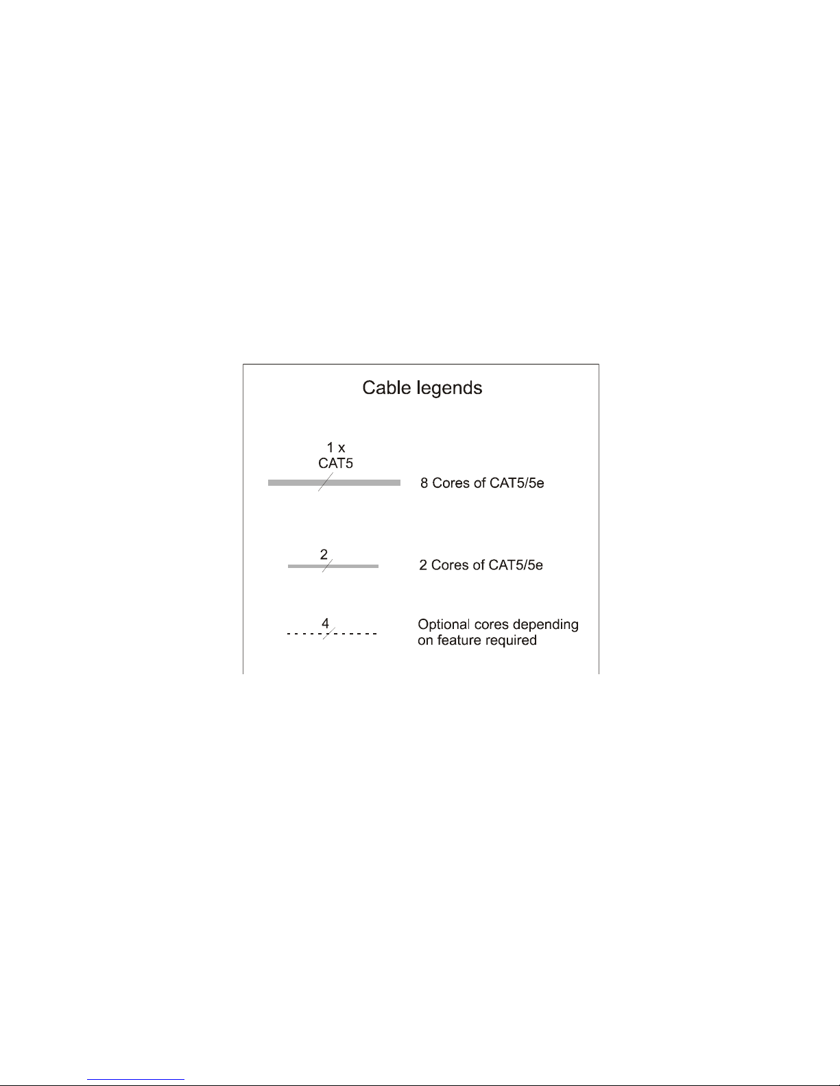
Cable overviews
Digibell Vandal Resistant System
PD-169 Issue 3B Installation Guide Page 15 of 56
Cable Overview
Diagram 1 – Full Isolation, 1 entrance up to 32 phones
Digibell Vandal Resistant System
PD-169 Issue 3B Installation Guide Page 16 of 56
Cable overview
Diagram 2 - Full isolation, 1 entrance 33 to 64 phones
Digibell Vandal Resistant System
PD-169 Issue 3B Installation Guide Page 17 of 56
Cable overview
Diagram 3 - Zone isolation, 1 entrance up to 32 phones
 Loading...