

Page 1

XTend vB
Radio Frequency (RF) Module
User Guide
Page 2

Revision history—90001478
Revision Date Description
A December
2015
B May 2016
C May 2018 Added note on range estimation. Changed ICto ISED.
D June 2019 Added FCC publication 996369 related information. Changes for 2x06
Baseline release of the document.
Added information on the Australian variant. Updated cyclic sleep numbers.
Added the HS command.
firmware release.
Trademarks and copyright
Digi, Digi International, and the Digi logo are trademarks or registered trademarks in the United
States and other countries worldwide. All other trademarks mentioned in this document are the
property of their respective owners.
© 2018 Digi International Inc. All rights reserved.
Disclaimers
Information in this document is subject to change without notice and does not represent a
commitment on the part of Digi International. Digi provides this document “as is,” without warranty of
any kind, expressed or implied, including, but not limited to, the implied warranties of fitness or
merchantability for a particular purpose. Digi may make improvements and/or changes in this manual
or in the product(s) and/or the program(s) described in this manual at any time.
Warranty
To view product warranty information, go to the following website:
www.digi.com/howtobuy/terms
Customer support
Gather support information: Before contacting Digi technical support for help, gather the following
information:
Product name and model
Product serial number (s)
Firmware version
Operating system/browser (if applicable)
Logs (from time of reported issue)
Trace (if possible)
Description of issue
XTend vB RF Module User Guide
2
Page 3

Steps to reproduce
Contact Digi technical support: Digi offers multiple technical support plans and service packages.
Contact us at +1 952.912.3444 or visit us at www.digi.com/support.
Feedback
To provide feedback on this document, email your comments to
Include the document title and part number (XTend vB RF Module User Guide, 90001478 B) in the
subject line of your email.
techcomm@digi.com
XTend vB RF Module User Guide
3
Page 4

Contents
XTend vB RF Module User Guide
Applicable firmware and hardware 10
XTend replacement numbers 10
Certification overview 10
Technical specifications
General specifications 12
Performance specifications 12
Networking specifications 13
Power requirements 13
Cyclic sleep current (mA, average) 14
Regulatory conformity summary 14
Hardware
Connect the hardware 16
Mechanical drawings 17
Pin signals 17
DC characteristics (Vcc=2.8-5.5 VDC) 20
Outputs 20
Inputs 20
Modes
Transparent and API operating modes 22
Transparent operating mode 22
API operating mode 22
Additional modes 22
Command mode 22
Binary Command mode 22
Idle mode 23
Receive mode 23
Sleep modes 23
Shutdown mode 23
Transmit mode 23
Enter Command mode 23
Send AT commands 24
Exit Command mode 24
XTend vB RF Module User Guide
4
Page 5

Enter Binary Command mode 25
Exit Binary Command mode 25
Binary Command mode FAQs 25
Sleep modes 26
Pin Sleep (SM = 1) 27
Serial Port Sleep (SM = 2) 27
Cyclic Sleep Mode (SM = 4 - 8) 28
Operation
Serial interface 31
UART data flow 31
Serial data 31
Flow control 31
Data In (DIN) buffer and flow control 32
Data Out (DO) buffer and flow control 33
Configure the XTend vB RF Module
Configure the device using XCTU 35
Program the XTend vB RF Module
Programming examples 36
Connect the device to a PC 36
Modify a device address 36
Restore device defaults 37
Send binary commands 37
Query binary commands 38
Commands
Command mode options 41
AT (Guard Time After) 41
BT (Guard Time Before) 42
CC (Command Sequence Character) 42
CF (Number Base) 42
CN (Exit Command Mode) 43
CT (Command Mode Timeout) 43
E0 (Echo Off) 44
E1 (Echo On) 44
Diagnostic commands 44
%V (Board Voltage) 44
DB (Received Signal Strength) 45
GD (Receive Good Count) 45
HV (Hardware Version) 46
RC (Ambient Power - Single Channel) 46
RE (Restore Defaults) 46
RM (Ambient Power) 47
RP (RSSI PWM Timer) 48
SH (Serial Number High) 48
SL (Serial Number Low) 49
TP (Board Temperature) 49
XTend vB RF Module User Guide
5
Page 6

TR (Transmit Error Count) 50
VL (Firmware Version - Verbose) 50
VR (Firmware Version - Short) 50
WA (Active Warning Numbers) 51
WN (Warning Data) 51
WS (Sticky Warning Numbers) 53
HS (Hardware Series) 53
MAC/PHY commands 53
AM (Auto-set MY) 53
DT (Destination Address) 54
HP (Preamble ID) 54
ID (Network ID) 55
MK (Address Mask) 55
MT (Multi-transmit) 55
MY (Source Address) 56
RN (Delay Slots) 56
RR (Retries) 57
TT (Streaming Limit) 57
RF interfacing commands 58
BR (RF Data Rate) 58
FS (Forced Synch Time) 58
MD (RF Mode) 59
PB (Polling Begin Address) 60
PD (Minimum Polling Delay) 60
PE (Polling End Address) 60
PK (Maximum RF Packet Size) 61
PL (TX Power Level) 61
TX (Transmit Only) 62
Security commands 62
KY (AES Encryption Key) 63
Serial interfacing commands 63
AP (API Enable) 63
BD (Interface Data Rate) 64
CD (GP02 Configuration) 65
CS (GP01 Configuration) 66
FL (Software Flow Control) 66
FT (Flow Control Threshold) 66
NB (Parity) 67
RB (Packetization Threshold) 67
RO (Packetization Timeout) 68
RT (GPI1 Configuration) 68
SB (Stop Bits) 69
Sleep commands 69
FH (Force Wakeup Initializer) 69
HT (Time before Wake-up Initializer) 70
LH (Wakeup Initializer Timer) 70
PW (Pin Wakeup) 71
SM (Sleep Mode) 71
ST (Time before Sleep) 72
Special commands 72
WR (Write) 73
API operation
API mode overview 75
XTend vB RF Module User Guide
6
Page 7

API frame specifications 75
Calculate and verify checksums 77
Escaped characters in API frames 77
Frame descriptions
Modem Status - 0x8A 80
Description 80
Modem status codes 81
Examples 81
16-bit Transmit Request- 0x01 83
Description 83
Format 83
Examples 84
Transmit Status - 0x89 85
Description 85
Delivery status codes 86
Examples 86
16-bit Receive Packet - 0x81 88
Description 88
Format 88
Examples 89
Regulatory information
FCC (United States) 91
OEM labeling requirements 91
FCC notices 91
RF exposure statement 92
XTend vB RF Module antenna options 93
FCC publication 996369 related information 98
ISED (Innovation, Science and Economic Development Canada) 100
Labeling requirements 100
Transmitters for detachable antennas 100
Detachable antennas 100
ACMA (Australia) 101
Power requirements 101
Network configurations
Network topologies 103
Point-to-point networks 103
Point-to-multipoint networks 103
Peer to peer networks 104
Addressing 105
Address recognition 106
Basic communications 106
Streaming mode (default) 106
Multi-transmit mode 107
Repeater mode 108
Polling mode (basic) 112
Acknowledged communications: Acknowledged mode 113
Acknowledged mode connection sequence 113
XTend vB RF Module User Guide
7
Page 8

Polling mode (acknowledged) 114
Development Kit
Development Kit contents 117
Interface hardware 117
XTIB-R RS-232/485 Interface Board 118
Configuration switch 118
I/O and Power LEDs 119
Serial port 119
RSSI LEDs 119
Power connector 119
XTIB-R DIP switch 119
Adapters 121
NULL Modem Adapter (male-to-male) 121
NULL Modem Adapter (female-to-female) 122
Serial Loopback Adapter 122
Male DB-9 to RJ-45 Adapter 123
Female DB-9 to RJ-45 Adapter 123
Interface protocols 123
RS-232 operation 124
RS-485 (2-wire) operation 126
RS-485 (4-wire) and RS-422 operation 128
XTend vB RF Module User Guide
8
Page 9

XTend vB RF Module User Guide
The XTend vB RF Module was engineered to provide customers with an easy-to-use radio frequency
(RF) solution that provides reliable delivery of critical data between remote devices. The module
transfers a standard asynchronous serial data stream, operates within the ISM 900 MHz frequency
band and offers two RF data rates of 10 kb/s and 125 kb/s for the United States and Canada variant.
It offers two RF data rates of 10 kb/s and 105 kb/s for the Australia variant.
Applicable firmware and hardware 10
XTend replacement numbers 10
Certification overview 10
XTend vB RF Module User Guide
9
Page 10

XTend vB RF Module User Guide Applicable firmware and hardware
Applicable firmware and hardware
This manual supports the following firmware:
n 2xxx
It supports the following hardware:
n As the name suggests, the XTend vB RF Module is form factor and over the air compatible with
our XTend module.
XTend replacement numbers
The following table provides the part numbers you can use to replace XTend devices with the XTend
vB RF Module.
Legacy part number Replacement part number
XT09-MI XTP9B-DPM-001
XT09-SI XTP9B-DPS-001
XT09-MI-MESH XTP9B-DMM-001
XT09-SI-MESH XTP9B-DMS-001
Certification overview
The XTend vB RF Module contains an FCC/IC approved RF module. A separate variant of the XTend vB
RF Module contains an Australian approved RF module. For usage requirements, see Regulatory
information.
ISM (Industrial, Scientific and Medical) license-free 902-928 MHz frequency band.
Manufactured under ISO 9001:2000 registered standards.
XTend vB RF Module User Guide
10
Page 11

Technical specifications
The following tables provide the device's technical specifications.
WARNING! When operating at 1 W power output, observe a minimum separation distance
of 6 ft (2 m) between devices. Transmitting in close proximity of other devices can damage
the device's front end.
General specifications 12
Performance specifications 12
Networking specifications 13
Power requirements 13
Regulatory conformity summary 14
XTend vB RF Module User Guide
11
Page 12

Technical specifications General specifications
General specifications
The following table describes the general specifications for the devices.
Specification Value
Dimensions (RF/pin connectors not included) 3.70 x 6.10 x 0.48 cm (1.457 x 2.402 x 0.190 in)
Weight 16 g
RoHS Compliant
Manufacturing ISO 9001:2000 registered standards
Connector 20 pin 2 mm pitch header
Antenna connector options MMCX or RPSMA
Antenna impedance 50 Ω unbalanced
Operating temperature -40 °C to 85 °C
Maximum input RF level at antenna port 6 dBm
Digital outputs 2 output lines
Performance specifications
The following table describes the performance specifications for the devices.
Note Range figure estimates are based on free-air terrain with limited sources of interference. Actual
range will vary based on transmitting power, orientation of transmitter and receiver, height of
transmitting antenna, height of receiving antenna, weather conditions, interference sources in the
area, and terrain between receiver and transmitter, including indoor and outdoor structures such as
walls, trees, buildings, hills, and mountains.
Specification Value
Frequency range
RF data rate (software selectable)
Transmit power (software selectable)
Channels 10 hopping sequences share 50 frequencies
Outdoor line of sight 10 kb/s Up to 40 miles
902 to 928 MHz US/Canada
915 to 928 MHz Australia
10 kb/s to 125 kb/s US/Canada
10 kb/s to 105 kb/s Australia
Up to 30 dBm (see Power requirements)
1
125 kb/s Up to 7 miles
1
Estimated based on a 9 mile range test with dipole antennas.
XTend vB RF Module User Guide
12
Page 13

Technical specifications Networking specifications
Specification Value
Indoor range line of sight 10 kb/s Up to 1,000 feet (300 m)
125 kb/s Up to 500 feet (150 m)
Receiver sensitivity 10 kb/s -110 dBm
125 kb/s -100 dBm
UARTdata rate 1200-230400 baud
Networking specifications
The following table provides the networking specifications for the device.
Specification Value
Modulation Frequency Shift Keying
Spread Spectrum Frequency Hopping Spread Spectrum (FHSS)
Supported Network
Topologies (software
selectable)
Encryption 256-bit or 128-bit AES CBC encryption depending on region. 256-bit is only
Power requirements
The following table describes the power requirements for the XTend vB RF Module.
Specifications are given at 5 V, 25 °C unless otherwise noted.
Requirement Value
Supply voltage 2.8 to 5.5 VDC, 5 V typical
Receive current @ 5 V 35 mA
Transmit current See the following table
Shutdown mode current 1 µA
Sleep current < 147 µA
Peer-to-peer (master/slave relationship not required), point-topoint/point-to-multipoint
available on the North America variant. 128-bit is only available on
international variants.
XTend vB RF Module User Guide
13
Page 14

Technical specifications Regulatory conformity summary
Cyclic sleep current (mA, average)
Sleep mode Cycle time RF data rate Cyclic sleep current (mA, average)
SM = 8 16 seconds BR = 0 0.65
BR = 1 0.23
SM = 7 8 seconds BR = 0 1.13
BR = 1 0.31
SM = 6 4 seconds BR = 0 2.06
BR = 1 0.46
SM = 5 2 seconds BR = 0 3.77
BR = 1 0.77
SM = 4 1 second BR = 0 6.68
BR = 1 1.36
Transmit power level 21.5 dBm 27 dBm 30 dBm
Supply voltage range 2.8 to 5.5 V 3.2 to 5.5 V 4.75 to 5.5 V
Transmit current (5 V, typical) 260 mA 470 mA 710 mA
Transmit current (3.3 V, typical) 340 mA 615 mA N/A
Regulatory conformity summary
This table describes the agency approvals for the devices.
Nation Approval
United States Contains FCC ID: MCQ-XBPSX
Canada Contains IC: 1846A-XBPSX
Australia RCM
XTend vB RF Module User Guide
14
Page 15

Hardware
Connect the hardware 16
Mechanical drawings 17
Pin signals 17
DC characteristics (Vcc=2.8-5.5 VDC) 20
XTend vB RF Module User Guide
15
Page 16
Hardware Connect the hardware
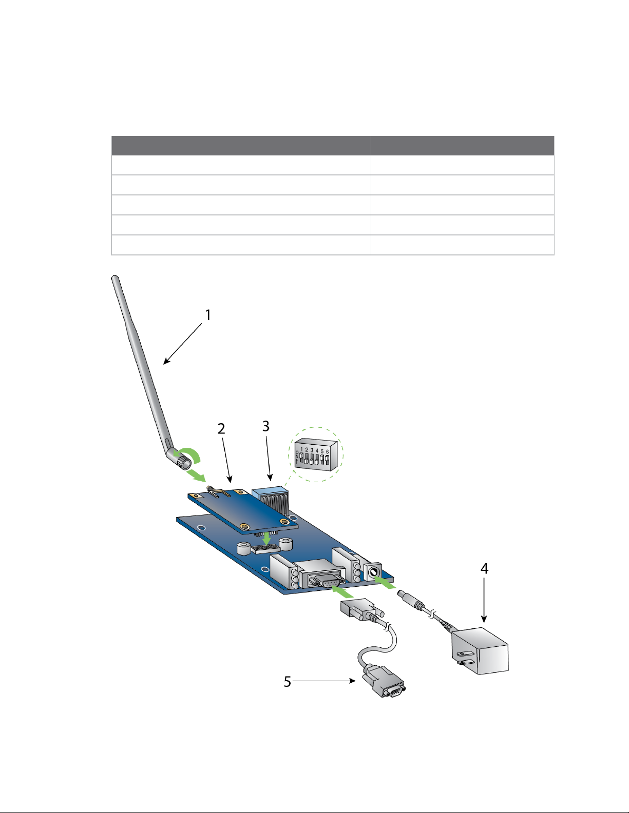
Connect the hardware
The following figure shows the XTend vB RF Module and accessories you need to get started and how
to connect them. The accessories are in the XT09-DK development kit.
Item Description
1 Antenna, RPSMA (female)
2 XTend vB module, RPSMA version shown
3 DIP switches
4 9 V power supply
5 DB9 serial cable
XTend vB RF Module User Guide
16
Page 17
Hardware Mechanical drawings
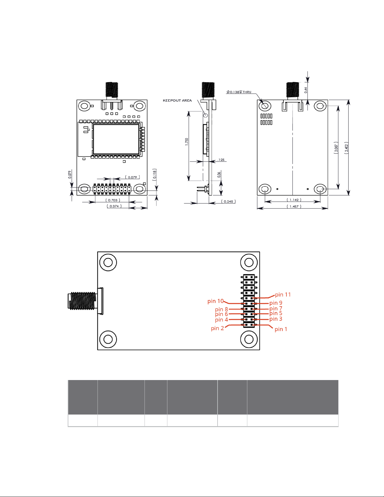
Mechanical drawings
The following drawings show the dimensions of the device.
Pin signals
The following drawing shows the location of the pins.
When integrating the module with a Host PC board, leave all lines that you do not use disconnected
(floating).
Pin
number Name I/O
High
impedance
during
shutdown
Must
connect Function
1 GND - - yes Ground
XTend vB RF Module User Guide
17
Page 18

Hardware Pin signals
High
impedance
Pin
number Name I/O
during
shutdown
Must
connect Function
2 VCC I - yes
3 GPO2/RXLED O - yes
4
5 DIN I yes yes Data In: Serial data entering the
6 DOUT O yes - Data Out: Serial data exiting the
7
TX _PWR
SHDN
O yes - Transmit_Power: Pin pulses low
I no yes Shutdown: Drive this pin high to
Power: 2.8 - 5.5 VDC
GPO2: General Purpose Output.
Default (CD = 2) drives this pin
low.
RX LED: Pin is driven high during
RF data reception; otherwise,
the pin is driven low. To enable
this pin, see CD (GP02
Configuration).
during RF transmission;
otherwise, the pin is driven high
to indicate power is on and the
device is not in Sleep or
Shutdown Mode.
device (from the UART host). For
more information, see .
module (to the UART host). For
more information, see .
enable normal operation and
low during Shutdown. Shutdown
enables the lowest power mode
available to the module.
8 SLEEP I yes -
XTend vB RF Module User Guide
SLEEP: By default, SLEEP is not
used. To configure this pin to
enable Sleep modes, refer to
Sleep modes, SM (Sleep Mode)
and PW (Pin Wakeup).
18
Page 19

Hardware Pin signals
High
impedance
Pin
number Name I/O
during
shutdown
Must
connect Function
9
10
11
GPO1 / CTS /
RS-485 TX_EN
RTS / CMD
CONFIG/RSSI
O yes -
I yes -
1
I
O
no - Configuration: Pin can be used
2
no -
GPO1: General Purpose Output.
Pin can be driven low or high.
CTS (Clear-to-Send): CTS is
enabled by default. When the pin
is driven low, the UART host is
permitted to send serial data to
the device. For more
information, see and CS (GP01
Configuration).
RS-485 Transmit Enable:
Enables RS-485 half and fullduplex communications. For
more information, see and CS
(GP01 Configuration).
RTS (Request-to-Send):
Not used by default. This pin can
be configured to allow the UART
host to regulate the flow of
serial data exiting the module.
For more information, see and
RT (GPI1 Configuration).
as a backup method for
entering Command mode during
power-up.
Receive Signal Strength
Indicator: By default, pin is used
as an RSSI PWM output after at
the conclusion of the power-up
sequence. The line is also pulled
high when the device goes to
sleep. The PWM output is 2.8 Vlevel. For more information, see
RP (RSSI PWM Timer).
12 - 20 Reserved / do
not connect
1
The RF module has a 10 kΩ internal pull-up resistor.
2
The RF module has a 10 kΩ internal pull-up resistor.
XTend vB RF Module User Guide
19
Page 20

Hardware DC characteristics (Vcc=2.8-5.5 VDC)
DC characteristics (Vcc=2.8-5.5 VDC)
Outputs
Pin
number Pin name
3 GPO2/RXLED VCC – 0.7 V 0.55 V
4 TX _PWR VCC – 0.7 V 0.55 V
6 DOUT VCC – 0.7 V 0.55 V
9 GPO1 / CTS / RS-485 TX_ENVCC – 0.7 V 0.55 V
1,2
11
CONFIG / RSSI 2.2 V 0.5 V
VOHminimum (IOH= -6
mA)
VOLmaximum (IOL = 6
mA)
Inputs
Pin number Pin name
5 DIN VCC * 0.75 VCC * 0.25
7 SHDN VCC * 0.75 0.7 V
8 SLEEP VCC * 0.75 VCC * 0.25
10 RTS / CMD VCC * 0.75 VCC * 0.25
3,4
11
CONFIG / RSSI VCC * 0.75 VCC * 0.25
VIHminimum VILmaximum
1
The RF Module has an internal 10 kΩ pull-up resistor to VCC.
2
When the line is enabled for use as RSSI PWM output and not CONFIG input. RSSI signal is a 2.8 V level PWM
signal.
3
The RF Module has an internal 10 kΩ pull-up resistor to VCC.
4
When the line is enabled for use as CONFIG input and not RSSI PWM output.
XTend vB RF Module User Guide
20
Page 21

Modes
The XTend vB RF Module is in Receive Mode when it is not transmitting data. The device shifts into the
other modes of operation under the following conditions:
n Transmit mode (Serial data in the serial receive buffer is ready to be packetized)
n Sleep mode
n Command Mode (Command mode sequence is issued)
Transparent and API operating modes 22
Additional modes 22
Sleep modes 26
XTend vB RF Module User Guide
21
Page 22

Modes Transparent and API operating modes
Transparent and API operating modes
The firmware operates in several different modes. Two top-level modes establish how the device
communicates with other devices through its serial interface: Transparent operating mode and API
operating mode.
Transparent operating mode
Devices operate in this mode by default. The device acts as a serial line replacement when it is in
Transparent operating mode. The device queues all UART data it receives through the DIN pin for RF
transmission. When a device receives RF data, it sends the data out through the DOUT pin.
API operating mode
API operating mode is an alternative to Transparent operating mode. API mode is a frame-based
protocol that allows you to direct data on a packet basis. The device communicates UART data in
packets, also known as API frames. This mode allows for structured communications with computers
and microcontrollers.
The advantages of APIoperating mode include:
n It is easier to send information to multiple destinations
n The host receives the source address for each received data frame
n You can change parameters without entering Command mode
n You can query or set a configuration parameter while a pending command—for example ND—is
in progress. This cannot be done in Command mode.
For more information, see API frame specifications.
Additional modes
In addition to the serial communication modes, several modes apply to how to configure devices and
how devices communicate with each other.
Command mode
Command mode is a state in which the firmware interprets incoming characters as commands.
Command mode allows you to modify the device’s firmware using parameters you can set using AT
commands. When you want to read or set any setting of the device, you have to send it an AT
command. Every AT command starts with the letters "AT" followed by the two characters that identify
the command the device sends and then by some optional configuration values. For more details, see
Enter Command mode.
Binary Command mode
Binary Command mode allows you to configure a device at a faster rate than AT commands will allow.
Using binary commands to send and receive parameter values is the fastest way to change the
operating parameters of the device. Use binary commands to:
n Sample signal strength and/or error counts;
n Change device addresses and channels for polling systems when a quick response is necessary.
For more details, see Enter Binary Command mode and DB (Received Signal Strength).
XTend vB RF Module User Guide
22
Page 23

Modes Additional modes
Idle mode
When not receiving or transmitting data, the device is in Idle mode. During Idle mode, the device
listens for valid data on the serial port.
Receive mode
If a destination node receives a valid RF packet, the destination node transfers the data to its serial
transmit buffer. For the serial interface to report receive data on the RF network, that data must
meet the following criteria:
n ID match
n Channel match
n Address match
Sleep modes
Sleep Modes enable the device to enter states of low-power consumption when not in use. The device
supports three software sleep modes:
n Pin Sleep: the host controls this
n Serial Port Sleep: wakes when it detects serial port activity
n Cyclic Sleep: wakes when it detects RF activity
For more information, see Sleep modes.
Shutdown mode
Shutdown mode offers the lowest power mode available to the device. This is helpful for applications
that must keep power consumption to a minimum during idle periods.
When you drive the SHDN pin (pin 7) low, it forces the device into Shutdown mode. This halts any
communication in progress (transmit or receive) and any buffered data is lost. For any other mode of
operation, you must drive or pull SHDN high.
Immediately after the SHDN pin changes states from low to high, the device resets. After reset, the
application must observe a delay time of <100 ms.
While SHDN is driven low, the device sets the following pins to high impedance: DCD, TX_PWR, RX LED,
DO and CTS. The SHDN line is driven low during shutdown.
The following input pins may continue to be driven by external circuitry when in shutdown mode: RTS,
DI and SHDN.
Because the DO pin is set to high impedance during Shutdown, if the XTend vB RF Module is connected
to a processor, the UART receive pin could be floating. Place a weak pull-up between the device and
the microcontroller so that the application does not misinterpret noise as data.
Transmit mode
When the device receives serial data and is ready to packetize it, the device exits Idle mode and
attempts to transmit the serial data.
Enter Command mode
There are two ways to enter Command mode:
XTend vB RF Module User Guide
23
Page 24
Modes Additional modes
1. To get a device to switch into this mode, you must issue a unique string of text in a special way:
+++ (default). When the device sees a full second of silence in the data stream followed by the
string +++ (without Enter or Return) and another full second of silence, it knows to stop
sending data through and start accepting commands locally.
Do not press Return or Enter after typing +++ because it will interrupt the guard time silence
and prevent you from entering Command mode.
2. If a serial break (DIN held low) signal is sent for over five seconds, the device resets, and it
boots into Command mode with default baud settings (9600 baud).
3. If a serial break is observed upon boot, Command mode will similarly be entered.
The device sends the letters OK followed by a carriage return out of the UART to indicate that it
entered Command mode.
You can customize the guard times and timeout in the device’s configuration settings. See CC
(Command Sequence Character), BT (Guard Time Before) and AT (Guard Time After).
Send AT commands
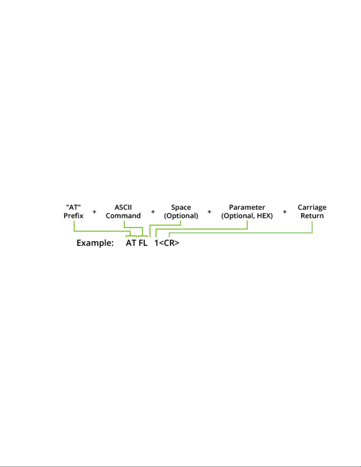
Once the device enters Command mode, use the syntax in the following figure to send AT commands.
Every AT command starts with the letters AT, which stands for "attention." The AT is followed by two
characters that indicate which command is being issued, then by some optional configuration values.
To read a parameter value stored in the device’s register, omit the parameter field.
The preceding example enables software flow control.
Multiple AT commands
You can send multiple AT commands at a time when they are separated by a comma in Command
mode; for example, ATSH,SL.
Parameter format
Refer to the list of AT commands for the format of individual AT command parameters. Valid formats
for hexidecimal values include with or without a leading 0x for example FFFF or 0xFFFF.
Response to AT commands
When reading parameters, the device returns the current parameter value instead of an OK message.
Exit Command mode
1. Send followed by a carriage return.
or:
2. If the device does not receive any valid AT commands within the time specified by, it returns to
Transparent or API mode. The default Command mode timeout is10seconds.
For an example of programming the device using AT Commands and descriptions of each configurable
parameter, see AT commands.
XTend vB RF Module User Guide
24
Page 25

Modes Additional modes
1. Send CN (Exit Command Mode) followed by a carriage return.
or:
2. If the device does not receive any valid AT commands within the time specified byCT
(Command Mode Timeout), it returns to Transparent or API mode. The default Command mode
timeout is10seconds.
For an example of programming the device using AT Commands and descriptions of each configurable
parameter, see Commands.
Enter Binary Command mode
To enter Binary Command mode, you must first be in Command mode:
1. Set RT to 1; see RT (GPI1 Configuration).
2. Assert CMD by driving pin 10 high to enter Binary Command mode.
3. Disable hardware flow control.
CTS (pin ) is high when the firmware executes a command. That is why you must disable hardware
flow control, because CTS holds off parameter bytes.
Exit Binary Command mode
To exit Binary Command mode, de-assert CMD by driving pin 10 low.
Binary Command mode FAQs
Since sending and receiving binary commands takes place through the same serial data path as live
data, interference between the two types of data can be a concern. Some common questions about
using binary commands are:
n What are the implications of asserting CMD while the device is sending or receiving live data?
You must assert the CMD pin (pin 10) in order to send binary commands to the device. You can
assert the CMD pin to recognize binary commands anytime during the transmission or reception of
data.
The device only checks the status of the CMD signal at the end of the stop bit as the byte shifts
into the serial port.
The firmware does not allow control over when the device receives data, except by waiting for
dead time between bursts of communication.
If the command is sent in the middle of a stream of payload data, the device executes the
command in the order it is received. If the device is continuously receiving data, it waits for a break
in the data it receives before executing the command.
n After sending serial data, is there a minimum time delay before you can assert CMD?
n Is a time delay required after CMD is de-asserted before payload data can be sent?
The host must observe a minimum time delay of 100 µs after sending the stop bit of the command
byte before the host de-asserts the CMD pin. The command executes after the host sends all of its
associated parameters. If the device does not receive all of these parameters within 0.5 seconds,
the device returns to Idle mode.
XTend vB RF Module User Guide
25
Page 26

Modes Sleep modes
Note When a host sends parameters, they are two bytes long with the least significant byte sent first.
Binary commands that return one parameter byte must be written with two parameter bytes.
Example: to set PL to 3, send the following data: 0x3A 0x03 0x00 (Binary Command, LSB, MSB).
n How do I discern between live data and data received in response to a command?
To query command parameters using Binary Command mode, set the most significant bit of the
binary command. This can be accomplished by logically ORing (bit-wise) the binary command with
hexadecimal 0x80. The parameter bytes are returned in hexadecimal bytes with the least
significant bit first (if multiple bytes are returned).
Example: to query HP in Binary Command mode, instead of setting it, send 0x11 (HP binary
command) as 0x91 with no parameter bytes.
The device must be in Binary Command mode in order for the device to recognize a binary
command; see Enter Binary Command mode.
If the device is not in Binary Command mode (the RT parameter value is not 1), the device does not
recognize that the CMD pin is asserted and therefore does not recognize the data as binary
commands.
For an example of binary programming, see Send binary commands.
Sleep modes
For the device to enter one of the sleep modes, SM must have a non-zero parameter value, and it
must meet one of the following conditions:
1. The device is idle (no data transmission or reception) for the amount of time defined by the ST
parameter. ST is only active when SM = 2 or 4 - 8.
2. The host asserts SLEEP (pin 10). This only applies to the Pin Sleep option.
When in Sleep mode, the device does not transmit or receive data until it transitions to Idle mode.
Use the SM command to enable or disable all Sleep modes. The following table shows the transitions
into and out of Sleep modes.
Sleep
mode
(setting)
Pin Sleep
(SM = 1)
Transition into
Sleep mode
Assert (high) SLEEP pin. A
microcontroller can shut down
and wake devices via the
SLEEP pin.
The device completes a
transmission or reception
before activating Pin Sleep.
Transition out of Sleep
mode (wake)
De-assert (low) SLEEP pin SM < 147 µA
Related
commands
Power
consumption
XTend vB RF Module User Guide
26
Page 27

Modes Sleep modes
Sleep
mode
(setting)
Transition into
Sleep mode
Transition out of Sleep
mode (wake)
Related
commands
Power
consumption
Serial
Port
Sleep
(SM = 2)
Cyclic
Sleep
(SM = 4 -
8)
The SM (Sleep Mode) command is central to setting all Sleep Mode configurations. By default, Sleep
Modes are disabled (SM = 0) and the device remains in Idle/Receive Mode. When in this state, the
device remains constantly ready to respond to serial or RF activity.
Note When the device sleeps, the RSSI pin is pulled high by design.
Automatic transition to Sleep
Mode occurs after a userdefined period of inactivity (no
transmitting or receiving of
data).
Period of inactivity is defined
by the ST command.
The device transitions in and out of Sleep Mode in cycles
(you set the sleep interval of time using the SM command).
The cyclic sleep interval of time must be shorter than the
interval of time that is defined by the LH command.
You can force the device into Idle Mode using the SLEEP pin
if you send the PW command.
When a serial byte is
received on the DI pin
(SM), ST 7.3 mA
(SM), ST,
HT, LH, PW
See Power
requirements
Pin Sleep (SM = 1)
After enabling Pin Sleep, the SLEEP pin controls whether the device is active or sleeping. When the
host de-asserts SLEEP, the device is fully operational. When the host asserts SLEEP, the device
transitions to Sleep mode and remains in its lowest power-consuming state until the host de-asserts
the pin. This pin is only active if the device is setup to operate in this mode; otherwise the firmware
ignores the pin.
Once in Pin Sleep, the device de-asserts (high) CTS (pin 9) , indicating that other devices should not
send data to the device. The device also de-asserts (low) the TX_PWR line (pin 4) when the device is in
Pin Sleep mode.
You cannot assert the SLEEP (pin9) until the transmission of the second byte has started.
Note The device completes a transmission or reception before activating Pin Sleep.
Serial Port Sleep (SM = 2)
n Wake on serial port activity
Serial Port Sleep is a Sleep mode in which the device runs in a low power state until it detects serial
data on the DI pin.
The ST command determines the period of time that the device sleeps. Once it receives a character
through the DI pin, the device returns to Idle mode and is fully operational.
XTend vB RF Module User Guide
27
Page 28

Modes Sleep modes
Cyclic Sleep Mode (SM = 4 - 8)
Cyclic Sleep modes allow device wakes according to the times designated by the cyclic sleep settings.
If the device detects a wake-up initializer during the time it is awake, the device synchronizes with the
transmitting device and receives data after the wake-up initializer runs its duration. Otherwise, the
device returns to Sleep mode and continues to cycle in and out of activity until a wake-up initializer is
detected.
While the device is in Cyclic Sleep mode, it de-asserts (high) CTS (pin 9) to indicate not to send data to
the device. When the device awakens to listen for data, it asserts CTS and transmits any data received
on the DI pin. The device also de-asserts (low) the TX_PWR (pin 4) when it is in Cyclic Sleep mode.
The device remains in Sleep mode for a user-defined period of time ranging from 1 second to 16
seconds (SM parameters 4 through 8). After this interval of time, the device returns to Idle mode and
listens for a valid data packet. The listen time depends on the BR parameter setting. The default BR
setting of 1 requires at least a 35 ms wake time, while the BR setting of 0 requires a wake time of up
to 225 ms. If the device does not detect valid data on any frequency, it returns to Sleep mode. If it
detects valid data, it transitions into Receive mode and receives the incoming RF packets. The device
then returns to Sleep mode after a period of inactivity determined by the ST parameter.
You can also configure the device to wake from cyclic sleep when the SLEEP pin is de-asserted. To
configure a device to operate in this manner, you must send the PW (Pin Wake-up) command. When
you de-assert the SLEEP pin, it forces the device into Idle mode and it can begin transmitting or
receiving data. It remains active until it no longer detects data for the time that ST specifies, at which
point it resumes its low-power cyclic state.
Cyclic scanning
Each RF transmission consists of an RF initializer and payload. The RF initializer contains initialization
information and all receiving devices must wake during the wake-up initializer portion of data
transmission in order to synchronize with the transmitting device and receive the data.
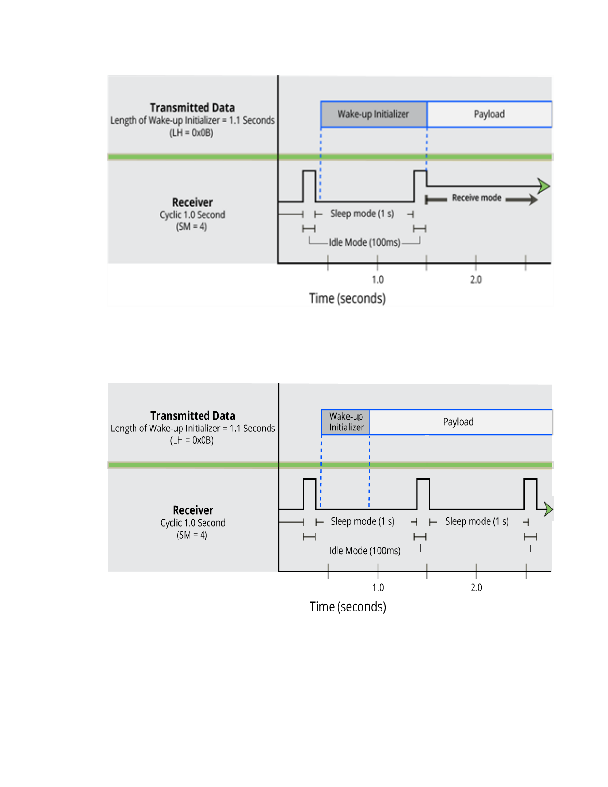
The cyclic interval time defined by the SM (Sleep Mode) command must be shorter than the interval
time defined by LH (Wake-up Initializer Timer) command.
Correct configuration (LH > SM)
In the following figure, the length of the wake-up initializer exceeds the time interval of Cyclic Sleep.
The receiver is guaranteed to detect the wake-up initializer and receive the accompanying payload
data.
The LH (Wakeup Initializer Timer) is only enabled if the HT (Time before Wake-up Initializer) is nondefault. The Wakeup Initializer is resent at the beginning of every packet unless the HT is set. Set HT
less than or equal to the ST (Time before Sleep) such that once the XTend vB RF Module has received
the Wakeup Initializer, another Wakeup Initializer need not be sent again until the expiration of the ST
has expired.
XTend vB RF Module User Guide
28
Page 29
Modes Sleep modes
Incorrect configuration (LH < SM)
Length of wake-up initializer is shorter than the time interval of Cyclic Sleep. This configuration is
vulnerable to the receiver waking and missing the wake-up initializer (and therefore also the
accompanying payload data).
XTend vB RF Module User Guide
29
Page 30

Operation
WARNING! When operating at 1 W power output, observe a minimum separation distance
of 6 ft (2 m) between devices. Transmitting in close proximity of other devices can damage
the device's front end.
Serial interface 31
UART data flow 31
Serial data 31
Flow control 31
XTend vB RF Module User Guide
30
Page 31

Operation Serial interface
Serial interface
The XTend vB RF Module interfaces to a host device through a TTL-level asynchronous serial port.
Through its serial port, the XTend vB RF Module can communicate with any UART voltage compatible
device or through a level translator to any serial device, for example: RS-232/485/422 or a USB
interface board.
UART data flow
Devices that have a UART interface connect directly to the pins of the XTend vB RF Module as shown in
the following figure. The figure shows system data flow in a UART-interfaced environment. Lowasserted signals have a horizontal line over the signal name.
Serial data
A device sends data to the XTend vB RF Module's UART through pin 5 DIN as an asynchronous serial
signal. When the device is not transmitting data, the signals should idle high.
For serial communication to occur, you must configure the UART of both devices (the microcontroller
and the XTend vB RF Module) with compatible settings for the baud rate, parity, start bits, stop bits,
and data bits.
Each data byte consists of a start bit (low), 8 data bits (least significant bit first) and a stop bit (high).
The following diagram illustrates the serial bit pattern of data passing through the device. The
diagram shows UART data packet 0x1F (decimal number 31) as transmitted through the device.
Flow control
The RTS and CTS device pins provide RTS and/or CTS flow control. CTS flow control signals the host to
stop sending serial data to the device. RTS flow control lets the host signal the device so it will not
send the data in the serial transmit buffer out the UART. The following diagram shows the internal
data flow, with the five most common pin signals.
XTend vB RF Module User Guide
31
Page 32

Operation Flow control
The firmware has Hardware flow control (CTS) configured by default. You must configure CTSflow
control on the host side for it to work.
You must configure Software flow control (XON) on both the host and device side for it to work.
If you change the CS command from 0, then CTSflow control will not work even if you have it
configured on the host.
Data In (DIN) buffer and flow control
When serial data enters the device through the DIN pin (pin 5), it stores the data in the DIN buffer until
it can process the data.
When the firmware satisfies the RB and RO parameter thresholds, the device attempts to initialize an
RF transmission. If the device is already receiving RF data, it stores the serial data in the device's DIN
buffer.
The device creates and transmits data packets when it meets one of the following conditions:
1. The device does not receive any serial characters for the amount of time set with in the RO
command; see RO (Packetization Timeout).
2. The device receives the maximum number of characters that fits in an RF packet.
3. The device receives the Command Mode sequence.
If the DIN buffer becomes full, you must implement hardware or software flow control in order to
prevent overflow (loss of data between the host and the device). To eliminate the need for flow
control:
1. Send messages that are smaller than the DIN buffer size. The size of the DIN buffer varies
according to the packet size (PK parameter) and the parity setting (NB parameter) you use.
2. Interface at a lower baud rate (BD parameter) than the RF data rate of the firmware (BR
parameter) of the firmware.
In the following situations, the DIN buffer may become full and overflow:
1. If you set the serial interface data rate higher than the RF data rate of the device, the device
receives data from the host faster than it can transmit the data over-the-air.
2. If the device receives a continuous stream of RF data or if the device monitors data on a
network, it places any serial data that arrives on the DIN pin (pin 5) in the DIN buffer. It
transmits the data in the DIN buffer over-the-air when the device no longer detects RF data in
the network.
XTend vB RF Module User Guide
32
Page 33

Operation Flow control
Hardware flow control (CTS)
The firmware asserts CTS before the DIN buffer is full so it has time to send the signal and the host
has time to stop sending data.
When the DIN buffer is full, the firmware de-asserts CTS (high) to signal the host to stop sending data;
refer to FT (Flow Control Threshold) and CS (GP01 Configuration).
The firmware re-asserts CTS after the DIN buffer has 34 bytes of memory available.
Hardware flow control (RTS)
If you enable RTS for flow control (RT parameter = 2), the device will not send data out the DOUT
buffer as long as the RTS pin (pin 10) is de-asserted.
Software flow control (XON/OFF)
Use FL to enable XON/XOFF software flow control. This option only works with ASCII data.
Data Out (DO) buffer and flow control
When a device receives RF data, the data enters the DOUT buffer and the device sends it out the serial
port to a host device. Once the DOUT buffer reaches capacity, it loses any additional incoming RF data.
The DOUT buffer stores at least 2.1 kB.
In the following situations, the DOUT buffer may become full and overflow:
1. If the RF data rate is set higher than the interface data rate of the device, the devices receives
data from the transmitting device faster than it can send the data to the host.
2. If the host does not allow the device to transmit data out from the DOUT buffer because of
being held off by hardware or software flow control.
Hardware flow control (RTS)
If you enable RTS for flow control (RT = 2), data will not be sent out the DO Buffer as long as RTS (pin
16) is de-asserted.
Software flow control (XOFF)
You can enable XON/XOFF software flow control using FL (Software Flow Control). This option only
works with ASCII data.
XTend vB RF Module User Guide
33
Page 34

Configure the XTend vB RF Module
Configure the device using XCTU 35
XTend vB RF Module User Guide
34
Page 35

Configure the XTend vB RF Module Configure the device using XCTU
Configure the device using XCTU
XBee Configuration and Test Utility (XCTU) is a multi-platform program that enables users to interact
with Digi radio frequency (RF) devices through a graphical interface. The application includes built-in
tools that make it easy to set up, configure, and test Digi RF devices.
For instructions on downloading and using XCTU, see the XCTU User Guide.
Click Discover devices and follow the instructions. XCTU should discover two XTend vB RF Modules.
Click Add selected devices.The devices appear in the Radio Modules list. You can click a module to
view and configure its individual settings. For more information on these items, see Commands.
Click Discover devices and follow the instructions. XCTU should discover the connected XTend vB RF
Modules using the provided settings.
Click Add selected devices.The devices appear in the Radio Modules list. You can click a module to
view and configure its individual settings. For more information on these items, see AT commands.
XTend vB RF Module User Guide
35
Page 36

Program the XTend vB RF Module
Programming examples
For steps on sending AT commands to a device, refer to:
n Send AT commands
n Exit Command mode
For more information, refer to the XCTU online help at:
docs.digi.com/display/XCTU/XCTU+Overview
Connect the device to a PC
The programming examples that follow require the installation of XCTU and a serial connection to a
PC. Digi stocks connector boards to facilitate interfacing with a PC.
1. Download XCTU from the Digi website:
digi.com/products/xbee-rf-solutions/xctu-software/xctu#resources
2. After the .exe file downloads to the PC, double-click the file to launch the XCTU Setup Wizard.
Follow the steps in the wizard to completely install XCTU.
3. Mount the device to an interface board, then connect the assembly to a PC.
4. Launch XCTU and click the Add devices tab on the upper left corner of the screen.
5. Verify that the baud rate and parity settings of the Serial/USB port match those of the device.
Note Failure to enter Command mode is commonly due to baud rate mismatch. Ensure that
the Baud Rate: setting on the Add radio device window matches the interface data rate of the
device. By default, the BD parameter = 9600 b/s.
Modify a device address
The following programming example shows you how to modify the device's destination address.
1. Once you add the device in XCTU, click on it in the Radio Modules pane to display the
Configuration working mode. This mode shows most of the device’s parameters that you can
edit.
2. Scroll down in the Radio Configuration pane until you find the parameter you want to edit, in
this case DT (Destination Address), or use the search box and type DT. XCTU automatically
scrolls to the selected parameter.
XTend vB RF Module User Guide
36
Page 37

Program the XTend vB RF Module Programming examples
3. When you locate the parameter, change its value, for example to 1A0D. If you do not save the
parameter, the color of the surrounding container is light green.
4. Click the write button to save the value to non-volatile memory; it is the pencil icon to the right
of the parameter . If you change other parameters but have not saved them, you can use the
Write radio settings button to save them. It is the white and blue pencil icon on the top of the
configuration panel .
Restore device defaults
The following programming example shows you how to restore a device's default parameters.
1. After establishing a connection between the device and a PC click the Configuration working
mode tab of XCTU .
2. Click the Load default firmware settings button and agree to restore the default values. The
button is the factory icon .
3. The restored parameters have a light green surrounding color, which means that they have
been changed but not saved.
4.
Click the Write module settings button to save all of the parameters simultaneously.
5. All the parameters surrounding box must change to gray indicating that their values are now
saved in the device's non-volatile memory.
Send binary commands
Example
Use XCTU's Serial Console tool to change the device's DT (Destination Address) parameter and save
the new address to non-volatile memory.
This example requires XCTU and a serial connection to a PC.
To send binary commands:
1. Set the RT command to 1 to enable binary command programming; do this in Command mode
or configure it through XCTU.
2. Drive pin 10 high to assert CMD by de-asserting the RTS line in XCTU. The device enters Binary
Command mode.
3. Send hexadecimal bytes (parameter bytes must be 2 bytes long). The next four lines are
examples, not required values:
00 (Send binary command DT)
0D (Least significant byte of parameter bytes)
1A (Most significant byte of parameter bytes)
08 (Send binary command WR)
4. Drive pin 10 low to de-assert CMD. After you send the commands, CTS (pin 9) de-asserts (driven
low) temporarily. The device exits Binary Command mode.
The default flow control is NONE, so if you are using XCTU, CTS is not an issue. However, you can still
observe the behavior of the CTS line by monitoring the CTS indicator in the terminal or console.
XTend vB RF Module User Guide
37
Page 38

Program the XTend vB RF Module Programming examples
Query binary commands
Example: use XCTU's Serial Console tool to query the device's DT (Destination Address) and DB
(Received Signal strength) parameters. In order to query a parameter instead of setting it, you must
logically OR the binary command byte with 0x80.
1. Set the RT command to 1 to enable binary command programming. To do this, you must either
be in Command mode or use XCTU to configure the device.
2. Assert CMD by driving pin 29 high. To do this de-assert the RTS line in XCTU.
3. Send hexadecimal bytes:
80 (Binary command DT (0x00) OR'ed with 0x80)
B6 (Binary command DB (0x36) OR'ed with 0x80)
4. Read the device's output for the parameter values of the two commands.
5. De-assert CMD by driving pin 29 low. The device exits Binary Command mode.
When querying commands in binary command mode, the output is the least significant byte followed
by the most significant byte and is always represented in hexadecimal values.
XTend vB RF Module User Guide
38
Page 39

Commands
The following table lists the AT and binary commands in the XTend vB RF Module firmware and links to
the description of the individual command.
By default, the device expects numerical values in hexadecimal since the default value of the CF
(Number Base) Parameter is 1. Hexadecimal values are designated by the 0x prefix and decimal
values by the d suffix.
AT command Binary command
%V (Board Voltage) 0x3B (59d)
AM (Auto-set MY) 0x41 (65d)
AP (API Enable)
AT (Guard Time After) 0x05 (5d)
BD (Interface Data Rate) 0x15 (21d)
BR (RF Data Rate) 0x39 (57d)
BT (Guard Time Before) 0x04 (4d)
CC (Command Sequence Character) 0x13 (19d)
CD (GP02 Configuration) 0x28 (40d)
CF (Number Base) --
CN (Exit Command Mode) 0x09 (9d)
CS (GP01 Configuration) 0x1F (31d)
CT (Command Mode Timeout) 0x06 (6d)
DB (Received Signal Strength) 0x36 (54d)
DT (Destination Address) 0x00 (0d)
E0 (Echo Off) 0x0A (10d)
E1 (Echo On) 0x0B (11d)
--
ER (Receive Count Error) 0x0F (15d)
FH (Force Wakeup Initializer) 0x0D (13d)
XTend vB RF Module User Guide
39
Page 40

Commands
AT command Binary command
FL (Software Flow Control) 0x07 (7d)
FS (Forced Synch Time) 0x3F (63d)
FT (Flow Control Threshold) 0x24 (36d)
GD (Receive Good Count) 0x10 (16d)
HP (Preamble ID) 0x11 (17d)
HS (Hardware Series)
HT (Time before Wake-up Initializer) 0x03 (3d)
HV (Hardware Version) --
ID (Network ID) 0x27 (39d)
KY (AES Encryption Key) 0x43 (67d)
LH (Wakeup Initializer Timer) 0x0C (12d)
MD (RF Mode) 0x31 (49d)
MK (Address Mask) 0x12 (18d)
MT (Multi-transmit) 0x3E (62d)
MY (Source Address) 0x2A (42d)
NB (Parity) 0x23 (35d)
PB (Polling Begin Address) 0x45 (69d)
PD (Minimum Polling Delay) 0x47 (71d)
PE (Polling End Address) 0x46 (70d)
PK (Maximum RF Packet Size) 0x29 (41d)
--
PL (TX Power Level) 0x3A (58d)
PW (Pin Wakeup) 0x1D (29d)
RB (Packetization Threshold) 0x20 (32d)
RC (Ambient Power - Single Channel) --
RE (Restore Defaults) 0x0E (14d)
RM (Ambient Power) --
RN (Delay Slots) 0x19 (25d)
RO (Packetization Timeout) 0x21 (33d)
RP (RSSI PWM Timer) 0x22 (34d)
XTend vB RF Module User Guide
40
Page 41

Commands Command mode options
AT command Binary command
RR (Retries) 0x18 (24d)
RT (GPI1 Configuration) 0x16 (22d)
SB (Stop Bits) 0x37 (55d)
SH (Serial Number High) 0x25 (37d)
SL (Serial Number Low) 0x26 (38d)
SM (Sleep Mode) 0x01 (1d)
ST (Time before Sleep) 0x02 (2d)
TP (Board Temperature) 0x38 (56d)
TR (Transmit Error Count) 0x1B (27d)
TT (Streaming Limit) 0x1A (26d)
TX (Transmit Only) 0x40 (64d)
VL (Firmware Version - Verbose) --
VR (Firmware Version - Short) 0x14 (20d)
WA (Active Warning Numbers) --
WN (Warning Data) --
WR (Write) 0x08 (8d)
WS (Sticky Warning Numbers) --
Command mode options
The following commands are Command mode option commands.
AT (Guard Time After)
Sets or displays the time-of-silence that follows the CC (Command Sequence Character) of the
Command mode sequence (BT + CC + AT). By default, one second must elapse before and after the
command sequence character.
The times-of-silence surrounding the Command Sequence Character prevent the device from
inadvertently entering Command mode.
Binary command
0x05 (5 decimal)
Parameter range
0x2 - 0x1770 [x 100 ms]
Default
0xA (1 second)
XTend vB RF Module User Guide
41
Page 42

Commands Command mode options
Bytes returned
2
BT (Guard Time Before)
Sets the DI pin silence time that must precede the Command Sequence Character (CC command) of
the Command mode sequence.
Binary command
0x04 (4 decimal)
Parameter range
0 - 0x1770 [x 100ms]
Default
0x0A (1 second)
Bytes returned
2
CC (Command Sequence Character)
Sets or displays the character the device uses between guard times of the AT Command mode
sequence. The AT Command mode sequence causes the device to enter Command Mode (from Idle
Mode).
Binary command
0x13 (19 decimal)
Parameter range
0x20 - 0x7F
Default
0x2B (ASCII “+”)
Bytes returned
1
CF (Number Base)
Sets or displays the command formatting setting.
The firmware always enters and reads the following commands in hex, no matter what the CF setting
is:
VR (Firmware Version)
HV (Hardware Version)
KY (AES Encryption Key)
Binary command
N/A
XTend vB RF Module User Guide
42
Page 43

Commands Command mode options
Command type
Command mode options
Parameter range
0 - 2
Parameter Configuration
0 Commands use the default number base; decimal commands may output units.
1 All commands are forced to unsigned, unit-less hex.
2 Commands use their default number base; no units are output.
Default
1
Bytes returned
1
CN (Exit Command Mode)
Makes the device exit Command mode.
Binary command
0x09 (9 decimal)
Parameter range
N/A
Default
N/A
Bytes returned
N/A
CT (Command Mode Timeout)
Set or read the Command mode timeout parameter. If a device does not receive any valid commands
within this time period, it returns to Idle mode from Command mode.
Use the CN (Exit Command mode) command to exit Command mode manually.
Binary command
0x06 (6 decimal)
Parameter range
0x2 - 0x53E2 [x 100 milliseconds]
Default
0xC8 (20 seconds)
XTend vB RF Module User Guide
43
Page 44

Commands Diagnostic commands
Bytes returned
2
E0 (Echo Off)
Turns off the character echo in Command mode.
By default, echo is off.
Binary command
0x0A (10 decimal)
Parameter range
N/A
Default
N/A
Bytes returned
N/A
E1 (Echo On)
Enables character echo in Command mode. Each character that you type echoes back to the terminal
when E1 is active. E0 (Echo Off) is the default.
Binary command
0x0B (11 decimal)
Parameter range
N/A
Default
N/A
Bytes returned
N/A
Diagnostic commands
The following AT commands are diagnostic commands. Diagnostic commands are typically volatile and
will not persist across a power cycle.
%V (Board Voltage)
Reads the supply voltage to the module's VCC (pin 2).
The conversion of the hex value returned by %V to Volts is VAL/65536 = Volts.
Example:
2.8 VDC = 2.8 * 65536 = 0x2CCCD
3.3 VDC = 3.3 * 65536 = 0x34CCD
XTend vB RF Module User Guide
44
Page 45

Commands Diagnostic commands
Sample output
3.27 V (when CF = 0)
345E3 (when CF = 1)
3.27 (when CF = 2)
Binary command
0x3B (59 decimal)
Parameter range
[read-only]:
0x2CCCA - 0x5BFFA (2.80 to 5.75 V)
Default
N/A
Bytes returned
4
1
DB (Received Signal Strength)
This command reports the received signal strength of the last received RF data packet or APS
acknowledgment. The DB command only indicates the signal strength of the last hop. It does not
provide an accurate quality measurement for a multihop link.
The DB command value is measured in -dBm. For example, if DB returns 0x50, then the RSSI of the last
packet received was -80 dBm. Set DB to 0 to clear the current value, and it will be updated with the
next valid packet received.
Parameter range
Observed ranges:
XBee-PRO - 0x1A - 0x58
XBee- 0x1A - 0x5C
Default
0x80000
GD (Receive Good Count)
Sets or displays the number of RF packets with valid MAC headers that the device receives
successfully on the RF interface. When the value reaches 0xFFFF, it stays there until you manually
change the maximum count value or reset the device.
Its parameter value is reset to 0 after every device reset and is not non-volatile; the parameter value
does not persist in the device's memory after a power-up sequence.
Pin, serial port or cyclic sleep modes do not reset the GD parameter.
Parameter range
0 - 0xFFFF
1
When CF = 1 (default), the firmware shows a hex integer that is equal to (voltage * 65536d).
XTend vB RF Module User Guide
45
Page 46

Commands Diagnostic commands
Default
0
Bytes returned
2
HV (Hardware Version)
Reads the device's hardware version number.
Binary command
N/A
Command type
Diagnostics
Parameter range
[read-only]: 0 - 0xFFFF
Default
N/A
Bytes returned
N/A
RC (Ambient Power - Single Channel)
Reads and reports the power level on a given channel.
Sample output
-78 dBm (when CF = 0)
4e (when CF = 1)
-78 (when CF = 2)
Binary command
N/A
Parameter range
[read-only]: 0 - 0x31 [dBm]
Default
N/A
Bytes returned
1
RE (Restore Defaults)
Restore device parameters to factory defaults.
XTend vB RF Module User Guide
46
Page 47

Commands Diagnostic commands
RE does not cause the device to store default values to non-volatile (persistent) memory. You must
send the WR command prior to power-down or reset to save the default settings in the device's nonvolatile memory.
Binary command
0x0E (14 decimal)
Parameter range
N/A
Default
N/A
Bytes returned
N/A
RM (Ambient Power)
Reads and reports power levels on all channels. If you do not provide a parameter, the device scans
the channels one time. If you do provide a parameter, the device scans the channels repeatedly for
the number of seconds that the parameter calls for. The firmware reports the maximum power level
seen for each channel (in other words, peak hold).
To implement a graphical spectrum analyzer, repeatedly send RM with no arguments and read the
resulting 50 power levels. This is easiest to do when CF = 1 or 2.
Sample output whenCF= 0: Ch 0: -100 dBm
Ch 1: -103 dBm
...
Ch 49: -99 dBm
Sample output whenCF= 1: 64 64
67
...
63
Sample output whenCF= 2: 100 100
-103
...
-99
Binary command
N/A
Command type
Diagnostics
XTend vB RF Module User Guide
47
Page 48

Commands Diagnostic commands
Parameter range
no parameter - 0x7D0
Default
N/A
Bytes returned
2
RP (RSSI PWM Timer)
Enables a pulse-width modulated (PWM) output on the CONFIG /RSSI pin (pin 11). We calibrate the pin
to show the difference between received signal strength and the sensitivity level of the device. PWM
pulses vary from zero to 95 percent. Zero percent means the RF signal the device receives is at or
below the device's sensitivity level.
The following table shows dB levels above sensitivity and PWM values. The total time period of the
PWM output is 8.32 ms. PWM output consists of 40 steps, so the minimum step size is 0.208 ms.
dB above sensitivity PWM percentage (high period / total period)
10 30%
20 45%
30 60%
A non-zero value defines the time that PWM output is active with the RSSI value of the last RF packet
the device receives. After the set time when the device has not received RF packets, it sets the PWM
output low (0 percent PWM) until the device receives another RF packet. It also sets PWM output low
at power-up. A parameter value of 0xFF permanently enables PWM output and always reflects the
value of the last received RF packet.
The PWM output and Config input share the CONFIG /RSSI pin. When the device is powered, the Config
pin is an input. During the power-up sequence, if RP is a non-zero value, the firmware configures the
Config pin as an output and sets it low until the device receives the first RF packet. With a non-zero RP
parameter, the CONFIG pin is an input for RP ms after power up.
Binary command
0x22 (34 decimal)
Parameter range
0 - 0xFF [x 100 ms]
Default
0x20 (3.2 seconds)
Bytes returned
1
SH (Serial Number High)
Displays the device's serial number high word.
XTend vB RF Module User Guide
48
Page 49

Commands Diagnostic commands
Binary command
0x25 (37 decimal)
Parameter range
0x0 - 0xFFFF [read-only]
Default
Varies
Bytes returned
2
SL (Serial Number Low)
Displays the serial number low word of the device.
Binary command
0x26 (38 decimal)
Parameter range
0 - 0xFFFF [read-only]
Default
Varies
Bytes returned
2
TP (Board Temperature)
The current module temperature in degrees Celsius in 8-bit two’s compliment format. For example
0x1A = 26 °C, and 0xF6 = -10 °C.
Sample output
26 C when CF = 0
1A when CF = 1
26 when CF = 2
Binary command
0x38 (56 decimal)
Parameter range
0 - 0x7F [read-only]
Default
N/A
Bytes returned
1
XTend vB RF Module User Guide
49
Page 50

Commands Diagnostic commands
TR (Transmit Error Count)
Reads the number of RF packets where retries expire without receiving an ACK (when RR > 0).
Binary command
0x1B (27 decimal)
Parameter range
0 - 0xFFFF
Default
0
Bytes returned
2
VL (Firmware Version - Verbose)
Reads the verbose firmware version of the device.
Binary command
N/A
Parameter range
Returns a string
Default
0
Bytes returned
2
VR (Firmware Version - Short)
Reads the firmware version on a device.
Firmware versions contain four significant digits: A.B.C.D. If B = 2, the device is programmed for
operation in Australia only.
Binary command
0x14 (20 decimal)
Parameter range
[read-only]: 0 - 0xFFFF
Default
N/A
Bytes returned
2
XTend vB RF Module User Guide
50
Page 51

Commands Diagnostic commands
WA (Active Warning Numbers)
Reports the warning numbers of all active warnings, one warning number per line. It does not show
further information and does not reset warning counts. For information on what the warning numbers
mean, see WN (Warning Data).
Sample output (indicates warnings 1 and 3 are currently active)
1
3
OK
Binary command
N/A
Command type
Diagnostics
Parameter range
Returns a string: one warning number per line.
Default
N/A
Bytes returned
N/A
WN (Warning Data)
Reports the following data for all active and sticky warnings:
n Warning number and description
n Number of occurrences since the last WN or WS command
n Whether the warning is currently active
WN does not display warnings that are not currently active and have not been active since the last
issuance of the WN or WS commands. WN resets all non-zero warning counts except for warnings that
are presently active, which are set to 1.
Sample output
Warning 4: Over-temperature
5 occurrences; presently inactive.
Warning
# Description
1 Under-voltage. This is caused if the supply voltage falls below the minimum threshold for
the lowest power level (2.8 V). If/when the voltage rises above the threshold, the warning
is deactivated. The device does not transmit below this voltage threshold.
XTend vB RF Module User Guide
51
Page 52

Commands Diagnostic commands
Warning
# Description
2 Deprecated.
3 Under-temperature. This is caused if the temperature sensed by the device is less than -
40° C. The device does not artificially limit operation while this warning is active, but
device functionality is not guaranteed.
4 Over-temperature. This is caused if the temperature sensed by the device is greater than
105° C. The device does not allow transmission nor reception while this warning is active.
The warning is deactivated when the temperature falls below 100° C.
5
6 Deprecated.
7 Default configuration parameters in flash. This is caused if user-modifiable parameters
8 Default factory configuration parameters in flash. This is caused if the factory
9 Watchdog reset occurred.
10
11
Power reduced. This is caused if the transmit power has to be reduced from the level
programmed by PL due to insufficient supply voltage.
PL4: 30 dBm (1 Watt) power level requires 4.75 V or higher.
PL3: 27 dBm (500 mW) power level requires 3.2 V or higher.
PL2 - PL0: 21.5 dBm (100 mW) power levels require 2.8 V or higher.
(i.e. those stored by WR) in flash are all the compiled-in default values. This is caused if
the user configuration is found to be not present or invalid at power-up and there is no
custom configuration, or if no user-modifiable parameters have been modified from the
compiled-in defaults. Modification of one or more parameters without the subsequent
WR to commit the changes to flash will not deactivate this warning, since it reflects the
status of the parameters in flash. This warning does not reflect usage of the custom
configuration defaults, only usage of the compiled-in defaults.
parameters in flash are all the default values. This is caused if the factory configuration is
found to be not present or invalid at power-up, or if no factory parameters have been
modified.
PK
was reduced byBR.
RB
was reduced byPK.
12 One or more parameters overridden due to conflict.
Binary command
N/A
Command type
Diagnostics
Parameter range
Returns a string
Default
N/A
XTend vB RF Module User Guide
52
Page 53

Commands MAC/PHY commands
Bytes returned
N/A
WS (Sticky Warning Numbers)
Reports warning numbers of all warnings active since the last use of WS or WN, including any
warnings that are currently active. WS also resets all non-zero warning counts, except for warnings
that are presently active, which are set to 1.
Binary command
N/A
Command type
Diagnostics
Parameter range
[read-only]: 1 - 8
Default
N/A
Bytes returned
1
The following AT commands are firmware commands.
HS (Hardware Series)
Read the device's hardware series number.
Parameter range
N/A
Default
0x2A00 - set in the firmware
MAC/PHY commands
The following AT commands are MAC/PHY commands.
AM (Auto-set MY)
Sets the MY (Source Address) parameter from the factory-set serial number of the device. The
address consists of bits 29, 28 and 13-0 of the serial number, in that order.
Sending AM displays the address.
Binary command
0x41 (65 decimal)
Parameter range
N/A
XTend vB RF Module User Guide
53
Page 54

Commands MAC/PHY commands
Default
N/A
Bytes returned
N/A
DT (Destination Address)
Sets or displays the networking address of a device. The devices use three filtration layers:
n Vendor ID Number (ID)
n Channel (HP)
n Destination Address (DT)
Binary command
0x00 (0 decimal)
Parameter range
0 - 0xFFFF
Default
0
Bytes returned
2
HP (Preamble ID)
Set or read the device's hopping channel number. A channel is one of three layers of filtration available
to the device.
In order for devices to communicate with each other, the devices must have the same channel
number since each channel uses a different hopping sequence. Devices can use different channels to
prevent devices in one network from listening to transmissions of another.
When a device receives a packet it checks HP before the network ID, as it is encoded in the preamble
and the network ID is encoded in the MAC header.
Binary command
0x11 (17 decimal)
Parameter range
0 - 9
Default
0
Bytes returned
1
XTend vB RF Module User Guide
54
Page 55

Commands MAC/PHY commands
ID (Network ID)
Sets or displays the Vendor Identification Number (VID) of the device. Devices must have matching
VIDs in order to communicate. If the device uses OEM network IDs, 0xFFFF uses the factory value.
Binary command
0x27 (39 decimal)
Parameter range
0x10 - 0x7FFF (user-settable)
0 - 0x9 and 0x8000 - 0xFFFF (factory-set)
Default
0x3332
N/A
Bytes returned
2
MK (Address Mask)
Sets or read the device's Address Mask.
All RF data packets contain the Destination Address of the transmitting (TX) device. When a device
receives a packet, the TX device's Destination Address is logically combined bitwise (in other words,
joined with AND) with the Address Mask of the receiving (RX) device. The resulting value must match
the Destination Address or Address Mask of the RX device for the packet to be received and sent out
the RX device's DO (Data Out) pin. If the combined value does not match the Destination Address or
Address Mask of the RX device, it discards the packet.
The firmware treats all 0 values as irrelevant and ignores them. For more information, see Addressing.
Binary command
0x12 (18 decimal)
Parameter range
0 - 0xFFFF
Default
0xFFFF
Bytes returned
2
MT (Multi-transmit)
Enables multiple transmissions of RF data packets. When you enable Multi-transmit mode (MT > 0),
packets do not request an ACK from the receiving devices. MT takes precedence over RR, so if both
MT and RR are non-zero, then a device sends MT+1 packets with no ACK requests.
When a receiving device receives a packet with remaining forced retransmissions, it calculates the
length of the packet and inhibits transmission for the amount of time required for all retransmissions.
From that time on, the device inserts a random number of delay slots between 0 and RN before
XTend vB RF Module User Guide
55
Page 56

Commands MAC/PHY commands
allowing transmission from the receiving devices. This prevents all listening devices from transmitting
at once upon conclusion of a multiple transmission event (when RN > 0).
Note The actual number of forced transmissions is the parameter value plus one. For example, if MT =
1, a devices sends two transmissions of each packet.
For more information, see Multi-transmit mode.
Binary command
0x3E (62d)
Command type
MAC/PHY
Parameter range
0 - 0xFF
Default
0 (no forced retransmissions)
Bytes returned
1
MY (Source Address)
Sets or displays the Source Address of a device.
For more information, see DT (Destination Address) and Addressing.
Binary command
0x2A (42 decimal)
Parameter range
0 - 0xFFFF
Default
0xFFFF (Disabled - DT (Destination Address) parameter serves as both source and destination
address).
Bytes returned
2
RN (Delay Slots)
Sets or displays the time delay that the transmitting device inserts before attempting to resend a
packet. If the transmitting device fails to receive an acknowledgment after sending a packet, it
inserts a random number of delay slots (ranging from 0 to (RN minus 1)) before attempting to resend
the packet. Each delay slot is 5 ms when BR = 1 and 54 ms when BR = 0.
If two devices attempt to transmit at the same time, the random time delay after packet failure only
allows one device to transmit the packet successfully, while the other device waits until the channel is
available for RF transmission.
RN is only applicable if:
XTend vB RF Module User Guide
56
Page 57

Commands MAC/PHY commands
n You enable retries using the RR command, or
n You insert forced delays into a transmission using the TT command
Binary command
0x19 (25 decimal)
Parameter range
0 - 0xFF [38 ms delay slots]
Default
0 (no delay slots inserted)
Bytes returned
1
RR (Retries)
Sets or displays the maximum number of retries sent for a given RF packet. When you enable RR (RR >
0), it enables RF packet retries and ACKs.
After transmitting a packet, the transmitting device waits to receive an ACK from a receiving device. If
it does not receive the ACK in the time that RN specifies, it transmits the original packet again. The
transmitting device transmits the RF packet repeatedly until it receives an ACK or until it sends the
packet RR times.
Note You must have retries enabled for all modules in the network for retries to work.
Binary command
0x18 (24 decimal)
Parameter range
0 - 0xFF
Default
0x0A (10 decimal)
Bytes returned
1
TT (Streaming Limit)
Sets or displays the limit on the number of bytes that a device can send before issuing a random delay.
If a device is sending a continuous stream of RF data, it inserts a delay that stops its transmission and
gives other devices time to transmit once it sends TT bytes of data. The random delay it inserts lasts
between 1 and RN + 1 delay slots .
You can use TT to simulate full-duplex behavior.
Binary command
0x1A (26 decimal)
XTend vB RF Module User Guide
57
Page 58

Commands RF interfacing commands
Parameter range
0 - 0xFFFF [bytes]
Default
0
Bytes returned
2
RF interfacing commands
The following AT commands are RF interfacing commands.
BR (RF Data Rate)
Sets and reads the device's RF data rate (the rate at which the device transmits and receives RF data
over-the-air).
Binary command
0x39 (57 decimal)
Parameter range
0 - 1
Parameter RF data rate
0 10 kb/s
1 125 kb/s
Default
1
Bytes returned
1
FS (Forced Synch Time)
The FS command only applies to streaming data. Normally, only the first packet of a continuous
stream contains the full RF initializer. The RF devices then remain synchronized for subsequent
packets of the stream.
You can use this parameter to periodically force an RF initializer during such streaming. Any break in
UART character reception that is long enough to drain the DI buffer and cause a pause in RF data
transmission also causes the firmware to insert an RF initializer on the next transmission.
Binary command
0x3F (63 decimal)
Command type
RF interfacing
XTend vB RF Module User Guide
58
Page 59

Commands RF interfacing commands
Parameter range
0 - 0xFFFF
[x 10 milliseconds]
Default
0
Bytes returned
2
MD (RF Mode)
Sets or displays the settings that enable the Polling and Repeater modes on the device.
Polling Mode: a Polling Base is responsible for polling remotes. A Polling Remote requires a poll from a
Polling Base in order to transmit.
Repeater Mode: a Repeater re-sends RF data unless the transmission is addressed to it or if it has
already detected the transmission. A Repeater End Node handles repeated messages, but will not
repeat the message over-the-air.
For more information, see Basic communications.
Binary command
0x31 (49 decimal)
Parameter range
0 - 6
Parameter Configuration
0
1 Reserved - not used
2 Reserved - not used
3 Polling Base
4 Polling Remote
5 Repeater
6 Repeater End Node
Default
0
Transparent Operation (Repeater Base)
Bytes returned
1
XTend vB RF Module User Guide
59
Page 60

Commands RF interfacing commands
PB (Polling Begin Address)
Sets or displays the device’s Polling Begin Address, which is the first address polled when you enable
Polling mode.
Binary command
0x45 (69 decimal)
Command type
RF interface
Parameter range
0 - 0xFFFF
Default
0
Bytes returned
2
PD (Minimum Polling Delay)
Sets or displays the Polling Delay (Base, MD = 3) or Polling Timeout (Remote, MD = 4).
Polling Delay (Base) is the time between polling cycles. The Polling Base starts the polling cycle after
sending the first poll. After the polling cycle completes, the timer restarts.
Polling Timeout (Remote) is the amount of time the remote device holds data from the serial port
before discarding it. The device transmits data entered within the PD time of the poll and does not
discard it.
Binary command
0x47 (71 decimal)
Command type
RF interface
Parameter range
0 - 0xFFFF (Base: [x 1ms], Remote: [x 10ms])
Default
0x64
Bytes returned
2
PE (Polling End Address)
Sets or displays the device’s Polling End Address; which is the last address polled when you enable
Polling mode.
Binary command
0x46 (70 decimal)
XTend vB RF Module User Guide
60
Page 61

Commands RF interfacing commands
Command type
RF interface
Parameter range
0 - 0xFFFF
Default
0
Bytes returned
2
PK (Maximum RF Packet Size)
Sets or displays the maximum size of RF packets that a device in Transparent operating mode (AP = 0)
transmits. You can use the maximum packet size along with the RB and RO parameters to implicitly
set the channel dwell time.
Changes to the PK parameter may have a secondary effect on the RB (Packetization Threshold)
parameter. RB must always be less than or equal to PK. If you change PK to a value that is less than
the current value of RB, the RB value lowers to be equal to PK.
Binary command
0x29 (41 decimal)
Parameter range
1 - 0x800 [Bytes]
Default
0x100 (BR = 0) 0x800 (BR = 1)
Bytes returned
2
1
PL (TX Power Level)
Sets or displays the power level at which the device transmits conducted power.
Binary command
0x3A (58 decimal)
Parameter range
0 - 4
1
When BR = 0 (9600 baud), the maximum PK value is 0x100 (256 bytes). When BR = 1 (115,200 baud), the
maximum PK value is 0x800 (2048 bytes).
XTend vB RF Module User Guide
61
Page 62

Commands Security commands
Parameter Configuration
PL0
PL1
PL2
PL3
PL4
Default
4
Bytes returned
1
21.5 dBm
27 dBm
30 dBm (1 Watt)
TX (Transmit Only)
Sets or displays the transmit or receive behaviors of the device. Setting a device to TX-only (TX = 1)
may reduce latency because the you can not limit the transmitting device to receiving data from other
devices.
Binary command
0x40 (64d)
Command type
RF Interfacing
Parameter range
0 - 1
Parameter Description
0 TX and RX
1 TX only
Default
0
Bytes returned
1
Security commands
The following AT commands are security commands.
XTend vB RF Module User Guide
62
Page 63

Commands Serial interfacing commands
KY (AES Encryption Key)
Sets the 256-bit Advanced Encryption Standard (AES) key for encrypting or decrypting data. Once set,
you cannot read the key out of the device by any means. The firmware encrypts the entire payload of
the packet using the key and computes the CRC across the ciphertext. When you enable encryption,
each packet carries an additional 16 bytes to convey the random cipher-block chaining (CBC)
Initialization Vector (IV) to the receiver(s). Set 256-bit key (64 hex digits) on multiple devices for
encrypted RF communication. Set to 0 to disable encryption. Reading the parameter returns a 0
(encryption disabled) or 1 (enabled). The key cannot be read for security reasons.
A device with the wrong key (or no key) receives encrypted data, but the data driven out the serial
port is meaningless. Likewise, a device with a key receives unencrypted data sent from a device
without a key, but the output is meaningless. Because it uses CBC mode, repetitive data appears
differently in different transmissions due to the randomly-generated IV.
Note For international (non-U.S.) variants of XTC devices, the encryption key is 128-bit AES. The
command operates the same except the key length is 16 bytes rather than 32 bytes. This pertains to
part numbers ending with 128, no matter which firmware version is loaded. This also pertains to the
Australia version of firmware 22xx.
Binary command
0x43 (67d)
Command type
Security
Parameter range
0 - (64 hex digits all set to 'F')
Default
0 (disabled)
Bytes returned
2
Serial interfacing commands
The following AT commands are serial interfacing commands.
AP (API Enable)
Set or read the API mode setting. The device can format the RF packets it receives into API frames
and send them out the serial port.
When you enable API, you must format the serial data as API frames because Transparent operating
mode is disabled.
Enables API Mode. The device ignores this command when using SPI. API mode 1 is always used.
Parameter range
0 - 2
XTend vB RF Module User Guide
63
Page 64

Commands Serial interfacing commands
Parameter Description
0
1 API Mode Without Escapes. The device packetizes all UART input and output data in API
2 API Mode With Escapes. The device is in API mode and inserts escaped sequences to
Default
0
Bytes returned
1
Transparent mode, API mode is off. All UART input and output is raw data and the
device uses the RO and RB parameters to delineate packets.
format, without escape sequences.
allow for control characters. The device passes XON (0x11), XOFF (0x13), Escape
(0x7D), and start delimiter 0x7E as data.
BD (Interface Data Rate)
Sets and reads the serial interface data rate (baud rate) between the device and the host. The baud
rate is the rate that the host sends serial data to the device.
When you make an update to the interface data rate, the change does not take effect until the host
issues the CN command and the device returns the OK response.
The BD parameter does not affect the RF data rate. If you set the interface data rate higher than the
RF data rate, you may need to implement a flow control configuration.
Non-standard interface data rates
The firmware interprets any value within 0x4B0 - 0x2580 and 0x4B00 - 0x1C9468 as an actual baud
rate. When the host sends a value above 0x4B0, the firmware stores the closest interface data rate
represented by the number in the BD register. For example, to set a rate of 19200 b/s, send the
following command line: ATBD4B00.
Note When using XCTU, you can only set and read non-standard interface data rates using the XCTU
Serial Console tool. You cannot access non-standard rates through the configuration section of XCTU.
Note The device does not support nonstandard baud rates between 9601 and 19199 baud. If you
attempt to set baud rates in this range, it will return an error.
When you send the BD command with a non-standard interface data rate, the UART adjusts to
accommodate the interface rate you request. In most cases, the clock resolution causes the stored
BD parameter to vary from the sent parameter. Sending ATBD without an associated parameter value
returns the value actually stored in the device’s BD register.
The following table provides the parameters sent versus the parameters stored.
Binary command
0x15 (21 decimal)
XTend vB RF Module User Guide
64
Page 65

Commands Serial interfacing commands
Parameter ranges
Parameter Configuration (b/s)
0 1200
1 2400
2 4800
3 9600
4 19200
5 38400
6 57600
Default
3
Bytes returned
4
CD (GP02 Configuration)
Selects or reads the behavior of the GPO2 line (pin 3).
Binary command
0x28 (40 decimal)
Parameter range
0 - 4
Parameter Configuration
0 RXLED
1 Static high
2 Static low
3 Reserved
4 RX LED (valid address only)
Default
2
Bytes returned
1
XTend vB RF Module User Guide
65
Page 66

Commands Serial interfacing commands
CS (GP01 Configuration)
Sets or displays the behavior of the GPO1 line (pin 9). This output can provide RS-232 flow control and
controls the TX enable signal for RS-485 or RS-422 operations.
By default, GP01 provides RS-232 Clear-to-Send (CTS ) flow control.
Binary command
0x1F (31 decimal)
Parameter range
0 - 4
Parameter Configuration
0 RS-232
1 RS-485 TX enable low
2 Static high
3 RS-485 TX enable high
4 Static low
Default
0
Bytes returned
1
CTS
flow control
FL (Software Flow Control)
The XON character used is 0x11 (17 decimal).
The XOFF character used is 0x13 (19 decimal).
Binary command
0x07 (7 decimal)
Parameter range
0 - 1
Default
0
Bytes returned
1
FT (Flow Control Threshold)
Sets or displays the flow control threshold.
De-assert CTS when the number of bytes specified by the FT parameter are in the DIN buffer. Reassert CTS when less than FT - 16 bytes are in the UART receive buffer.
XTend vB RF Module User Guide
66
Page 67

Commands Serial interfacing commands
Binary command
0x24 (36 decimal)
Parameter range
0x11 - 0xC00 [bytes]
Default
0xBBF (DI buffer size minus 0x11)
Bytes returned
2
NB (Parity)
Set or read the parity settings for UART communications.
Parameter range
Parameter Configuration
0
1 8-bit even
2 8-bit odd
3 8-bit mark
4 8-bit space
Default
0
Bytes returned
1
8-bit (no parity )
RB (Packetization Threshold)
Sets or displays the character threshold value.
RF transmission begins after a device receives data in the DIN buffer and meets either of the following
criteria:
n The UART receives RB characters
n The UART receive lines detect RO character times of silence after receiving at least 1 byte of
data
If a device lowers PK below the value of RB, RB is automatically lowered to match the PK value.
If RO = 0, the device must receive RB bytes before beginning transmission.
RB and RO criteria only apply to the first packet of a multi-packet transmission. If data remains in the
DIN buffer after the first packet, transmissions continue in a streaming manner until there is no data
left in the DIN buffer.
XTend vB RF Module User Guide
67
Page 68

Commands Serial interfacing commands
Binary command
0x20 (32 decimal)
Parameter range
0 - PK parameter value
(up to 0x800 bytes)
Default
0x800 (2048 bytes)
Bytes returned
2
RO (Packetization Timeout)
Set or read the number of character times of inter-character silence required before transmission
begins. For information on how ROworks with the RB command, see RB (Packetization Threshold).
When RO is the transmission-beginning criteria:
The actual time between the reception of the last character from the UART and the beginning of RF
transmission is at least 800 µsec longer than the actual RO time to allow for transmission setup. It is
also subject to 100-200 µsec of additional uncertainty, which could be significant for small values of RO
at high UART bit rates.
The firmware calculates the correct UART character time (10, 11, or 12 bits) based on the following
criteria:
n 1 start bit
n 8 data bits
n 0 or 1 parity bit (as determined by the NB command)
n 1 or 2 stop bits (as determined by SB command)
Binary command
0x21 (33 decimal)
Parameter range
0 - 0x53E2 [x UART character times]
Default
3
Bytes returned
2
RT (GPI1 Configuration)
Sets or displays the behavior of the GPI1 pin (pin 10) of the device. You can configure the pin to enable
Binary Command mode or RTS flow control.
Binary command
0x16 (22 decimal)
XTend vB RF Module User Guide
68
Page 69

Commands Sleep commands
Parameter range
0 - 2
Parameter Configuration
0 Disabled
1
2
Default
0 (disabled)
Bytes returned
1
Binary Command enable
RTS flow control enable
SB (Stop Bits)
Sets or displays the number of stop bits in the data packet.
Binary command
0x37 (55 decimal)
0x36 (54 decimal)
Parameter range
0 - 1
Parameter Configuration
0 One stop bit
1 Two stop bits
Default
0
Bytes returned
1
Sleep commands
The following AT commands are sleep commands.
FH (Force Wakeup Initializer)
Forces the device to send a wake-up initializer on the next transmission.
Only use FH with cyclic sleep modes active on remote devices.
You do not need to issue the WR (Write) command with FH.
XTend vB RF Module User Guide
69
Page 70

Commands Sleep commands
Binary command
0x0D (13 decimal)
Parameter range
N/A
Default
N/A
Bytes returned
N/A
HT (Time before Wake-up Initializer)
Sets or displays the time of inactivity (no serial or RF data is sent or received) before a transmitting
(TX)RF device sends a wake-up initializer. The main purpose of this command is to prevent devices
from sending the Long Header with every data packet. For more information on long headers, see LH
(Wakeup Initializer Timer).
For RX devices operating in Cyclic Sleep mode (SM = 4-8), set HT to be shorter than the ST command.
The TX device sends a wake-up initializer, which instructs all receiving (RX) devices to remain awake
to receive RF data.
From the perspective of the RX device: after HT time elapses and the inactivity timeout (ST command)
is met, the RX device goes into cyclic sleep. In cyclic sleep, the RX device wakes once per sleep interval
(SM command) to check for a wake-up initializer. When it detects a wake-up initializer, the device
stays awake to receive data. The wake-up initializer must be longer than the cyclic sleep interval to
ensure that sleeping devices detect incoming data.
When HT time elapses, the TX device knows it needs to send a wake-up initializer for all RX devices to
remain awake and receive the next transmission.
Binary command
0x03 (3 decimal)
Parameter range
0 - 0x53E2, 0xFFFF [x 100 ms]
Default
0xFFFF (wake-up initializer will not be sent)
Bytes returned
2
LH (Wakeup Initializer Timer)
Sets or displays the duration of time during which the wake-up initializer is sent. When receiving
devices are in Cyclic Sleep Mode, they power-down after a period of inactivity as specified by the ST
parameter and will periodically wake and listen for data transmissions. In order for the receiving
devices to remain awake, they must detect ~35 ms of the wake-up initializer.
You must use LH whenever a receiving device is operating in Cyclic Sleep mode. The wake-up
initializer time must be longer than the cyclic sleep time, which is set by the SM (Sleep Mode)
XTend vB RF Module User Guide
70
Page 71

Commands Sleep commands
parameter. If the wake-up initializer time is less than the Cyclic Sleep interval, the connection is at
risk of missing the wake-up initializer transmission.
Binary command
0x0C (12 decimal)
Parameter range
0 - 0xFF [x100 milliseconds]
Default
1
Bytes returned
1
PW (Pin Wakeup)
Enables or disables the sleep pin.
Under normal operation, a device in Cyclic Sleep mode cycles from an active state to a low-power
state at regular intervals until it is ready to receive data. If you set PW to 1, you can use the SLEEP pin
(pin 26) to wake the device from Cyclic Sleep. When you de-assert (low) the SLEEP pin, the device is
operational and will not go into Cyclic Sleep.
Once you assert the SLEEP pin, the device remains active for the period of time specified by the ST
parameter and returns to Cyclic Sleep mode if no data is ready to transmit. PW is only valid if Cyclic
Sleep is enabled.
Binary command
0x1D (29 decimal)
Parameter range
0 - 1
Parameter Configuration
0 Disabled
1 Enabled
Default
0
Bytes returned
1
SM (Sleep Mode)
Sets or displays the device's sleep mode settings, which configure the device to run in states that
require minimal power consumption.
XTend vB RF Module User Guide
71
Page 72

Commands Special commands
Binary command
0x01
Parameter range
0 - 8 (3 is reserved)
Parameter Description
0 Disabled
1 Pin Sleep
2 Serial Port Sleep
3 [reserved]
4 Cyclic 1 second sleep (RF module wakes every 1.0 seconds)
5 Cyclic 2 second sleep
6 Cyclic 4 second sleep
7 Cyclic 8 second sleep
8 Cyclic 16 second sleep
Default
0
Bytes returned
1
ST (Time before Sleep)
You can only use this command if you use SM to select Cyclic Sleep or Serial Port Sleep mode settings;
see SM (Sleep Mode).
Binary command
0x02 (2 decimal)
Parameter range
(AT + 3) - 0x53E2 [x 100 ms]
Default
0x64 (10 seconds)
Bytes returned
2
Special commands
The following commands are special commands.
XTend vB RF Module User Guide
72
Page 73

Commands Special commands
WR (Write)
Writes parameter values to non-volatile memory so that parameter modifications persist through
subsequent resets.
If you make changes without writing them to non-volatile memory, the device reverts to previously
saved parameters the next time it is powered on.
If the non-volatile user configuration is not correct, WR will re-attempt up to three times. If all three
attempts fail, the command returns an ERROR alert.
Binary command
0x08
Command type
Special
Parameter range
N/A
Default
N/A
Bytes returned
N/A
XTend vB RF Module User Guide
73
Page 74

API operation
API mode overview 75
XTend vB RF Module User Guide
74
Page 75

API operation API mode overview
API mode overview
By default, the XTend vB RF Module acts as a serial line replacement (Transparent operation), it
queues all UART data that it receive through the DI pin for RF transmission. When the device receives
an RF packet, it sends the data out the DO pin with no additional information.
The following behaviors are inherent to Transparent operation:
n If device parameter registers are to be set or queried, a special operation is required for
transitioning the device into Command Mode; refer to Enter Command mode.
n In point-to-multipoint systems, the host application must send XTend vBa if the receiving
device(s) need to distinguish between data coming from different remotes.
API operating mode is an alternative to transparent mode. API mode is a frame-based protocol that
allows you to direct data on a packet basis. It can be particularly useful in large networks where you
need to control the destination of individual data packets or when you need to know which node a
data packet was sent from. The device communicates UART data in packets, also known as API
frames. This mode allows for structured communications with serial devices. It is helpful in managing
larger networks and is more appropriate for performing tasks such as collecting data from multiple
locations or controlling multiple devices remotely.
API frame specifications
The firmware supports two API operating modes: without escaped characters and with escaped
characters. Use the AP command to enable either mode. To configure a device to one of these modes,
set the following AP parameter values:
AP command
setting Description
AP = 0
AP = 1
AP = 2
The APIdata frame structure differs depending on what mode you choose.
The firmware silently discards any data it receives prior to the start delimiter. If the device does not
receive the frame correctly or if the checksum fails, the device discards the frame.
Transparent operating mode, UARTserial line replacement with API modes
disabled. This is the default option.
API operation.
API operation with escaped characters (only possible on UART).
API operation (AP parameter = 1)
We recommend this API mode for most applications. The following table shows the data frame
structure when you enable this mode:
Frame fields Byte Description
Start delimiter 1 0x7E
Length 2 - 3 Most Significant Byte, Least Significant Byte
Frame data 4 - n API-specific structure
Checksum n + 1 1 byte
XTend vB RF Module User Guide
75
Page 76

API operation API mode overview
API operation-with escaped characters (AP parameter = 2)
Set API to 2 to allow escaped control characters in the API frame. Due to its increased complexity, we
only recommend this API mode in specific circumstances. API 2 may help improve reliability if the
serial interface to the device is unstable or malformed frames are frequently being generated.
When operating in API 2, if an unescaped 0x7E byte is observed, it is treated as the start of a new API
frame and all data received prior to this delimiter is silently discarded. For more information on using
this API mode, refer to the following knowledge base article:
http://knowledge.digi.com/articles/Knowledge_Base_Article/Escaped-Characters-and-API-Mode-2
The following table shows the structure of an API frame with escaped characters:
Frame fields Byte Description
Start delimiter 1 0x7E
Length 2 - 3 Most Significant Byte, Least Significant Byte Characters escaped if needed
Frame data 4 - n API-specific structure
Checksum n + 1 1 byte
Escape characters
When sending or receiving a UART data frame, you must escape (flag) specific data values so they do
not interfere with the data frame sequencing. To escape an interfering data byte, insert 0x7D and
follow it with the byte to be escaped XOR’d with 0x20. If not escaped, 0x11 and 0x13 are sent as is.
Data bytes that need to be escaped:
n 0x7E – Frame delimiter
n 0x7D – Escape
n 0x11 – XON
n 0x13 – XOFF
Example - Raw UART data frame (before escaping interfering bytes): 0x7E 0x00 0x02 0x23 0x11 0xCB
0x11 needs to be escaped which results in the following frame: 0x7E 0x00 0x02 0x23 0x7D 0x31 0xCB
Note In the previous example, the length of the raw data (excluding the checksum) is 0x0002 and the
checksum of the non-escaped data (excluding frame delimiter and length) is calculated as:
0xFF - (0x23 + 0x11) = (0xFF - 0x34) = 0xCB.
Start delimiter
This field indicates the beginning of a frame. It is always 0x7E. This allows the device to easily detect a
new incoming frame.
Length
Frame data
This field contains the information that a device receives or will transmit. The structure of frame data
depends on the purpose of the API frame:
XTend vB RF Module User Guide
76
Page 77

API operation API mode overview
Frame data
Start
delimiter Length
Frame
type
Data
Checksum
1 2 3 4 5 6 7 8 9 ... n n+1
0x7E MSB LSB
n Frame type is the API frame type identifier. It determines the type of API frame and indicates
APIframe type
Data
Single byte
how the Data field organizes the information.
n Data contains the data itself. This information and its order depend on the what type of frame
that the Frame type field defines.
Checksum
Calculate and verify checksums
To calculate the checksum of an API frame:
1. Add all bytes of the packet, except the start delimiter 0x7E and the length (the second and
third bytes).
2. Keep only the lowest 8 bits from the result.
3. Subtract this quantity from 0xFF.
To verify the checksum of an API frame:
1. Add all bytes including the checksum; do not include the delimiter and length.
2. If the checksum is correct, the last two digits on the far right of the sum equal 0xFF.
Example
Escaped characters in API frames
If operating in API mode with escaped characters (AP parameter = 2), when sending or receiving a
serial data frame, specific data values must be escaped (flagged) so they do not interfere with the
data frame sequencing. To escape an interfering data byte, insert 0x7D and follow it with the byte to
be escaped (XOR'ed with 0x20).
The following data bytes need to be escaped:
n 0x7E: start delimiter
n 0x7D: escape character
n 0x11: XON
n 0x13: XOFF
To escape a character:
1. Insert 0x7D (escape character).
2. Append it with the byte you want to escape, XOR'ed with 0x20.
In API mode with escaped characters, the length field does not include any escape characters in the
frame and the firmware calculates the checksum with non-escaped data.
XTend vB RF Module User Guide
77
Page 78

API operation API mode overview
Example: escape an API frame
To express the following API non-escaped frame in API operating mode with escaped characters:
Start delimiter Length Frame type
7E 00 0F 17 01 00 13 A2 00 40 AD 14 2E FF FE 02 4E 49 6D
You must escape the 0x13 byte:
1. Insert a 0x7D.
2. XOR byte 0x13 with 0x20: 13 ⊕ 20 = 33
The following figure shows the resulting frame. Note that the length and checksum are the same as
the non-escaped frame.
Start delimiter Length Frame type
7E 00 0F 17 01 00 7D 33 A2 00 40 AD 14 2E FF FE 02 4E 49 6D
The length field has a two-byte value that specifies the number of bytes in the frame data field. It does
not include the checksum field.
Frame Data
Data
Frame Data
Data
Checksum
Checksum
XTend vB RF Module User Guide
78
Page 79

Frame descriptions
The following sections describe the API frames.
Modem Status - 0x8A 80
Modem status codes 81
16-bit Transmit Request- 0x01 83
Transmit Status - 0x89 85
16-bit Receive Packet - 0x81 88
XTend vB RF Module User Guide
79
Page 80

Modem Status - 0x8A
Description
This frame type is emitted in response to specific conditions. The status field of this frame indicates
the device behavior.
Format
Frame
Offset Size
Field Description
0 8-
bit
1 16-
bit
3 8-
bit
Start
Delimiter
Length Number of bytes between the length and checksum.
Frame
type
Indicates the start of an API frame.
Modem Status - 0x8A
XTend vB RF Module User Guide
80
Page 81

Frame descriptions Modem status codes
Frame
Offset Size
Field Description
4 8-
bit
Modem
status
Complete list of modem statuses:
0x00 = Hardware reset or power up
0x01 =Watchdog timer reset
0x02 = Joined network
0x03 = Left network
0x06 = Coordinator started
0x07 = Network security key was updated
0x0B = Network woke up
0x0C = Network went to sleep
0x0D = Voltage supply limit exceeded
0x0E = Remote Manager connected
0x0F = Remote Manager disconnected
0x11 = Modem configuration changed while join in progress
0x12 = Access fault
0x13 = Fatal error
0x3B = Secure session successfully established
0x3C = Secure session ended
0x3D = Secure session authentication failed
0x3E = Coordinator detected a PAN ID conflict but took no action
0x3F = Coordinator changed PAN ID due to a conflict
0x32 = BLE Connect
0x33 = BLE Disconnect
0x34 = Bandmask configuration failed
0x35 = Cellular component update started
0x36 = Cellular component update failed
0x37 = Cellular component update completed
0x38 = XBee firmware update started
0x39 = XBee firmware update failed
0x3A = XBee firmware update applying
0x40 = Router PAN ID was changed by coordinator due to a conflict
0x42 = Network Watchdog timeout expired
0x80through0xFF = Stack error
Refer to the tables below for a filtered list of status codes that are
appropriate for specific devices.
EOF 8-
Checksum 0xFF minus the 8-bit sum of bytes from offset 3 tothis byte (between
bit
Modem status codes
Statuses for specific modem types are listed here.
Examples
Each example is written without escapes (AP = 1) and all bytes are represented in hex format. For
brevity, the start delimiter, length, and checksum fields have been excluded.
Boot status
When a device powers up, it returns the following API frame:
7E 00 02 8A 00 75
XTend vB RF Module User Guide
length and checksum).
81
Page 82

Frame descriptions Modem status codes
Frame type Modem Status
0x8A 0x00
Status Hardware Reset
XTend vB RF Module User Guide
82
Page 83

Frame descriptions 16-bit Transmit Request- 0x01
16-bit Transmit Request- 0x01
Response frame:Transmit Status - 0x89
Description
This frame type is used to send serial payload data as an RF packet to a remote device with a
corresponding 16-bit network address.
Note This frame format is deprecated and should only be used by customers who require
compatibility with legacy Digi RF products. For new designs, we encourage you to useTransmit
Request frame - 0x10to initiate API transmissions.
Format
The following table provides the contents of the frame. For details on frame structure, see API frame
format.
Frame
Offset Size
Field Description
0 8-bit Start
Delimiter
1 16-bit Length Number of bytes between the length and checksum.
3 8-bit Frame type
4 8-bit Frame ID
5 16-bit
7 8-bit
8-n variable RF data
Destination
address
Options A bit field of options that affect the outgoing transmission:
Indicates the start of an API frame.
16-bit Transmit Request- 0x01
Identifies the data frame for the host to correlate with a
subsequent response.
If set to 0, the device will not emit a response frame.
Set to the 16-bit network address of the destination device.
If set to 0xFFFF, the broadcast address is used.
n Bit 0: Disable MAC ACK [0x01]
n Bit 1: Reserved (set to 0)
n Bit 2: Send packet with Broadcast PAN ID [0x04]
l 802.15.4 firmwares only
Note Option values may be combined. Set all unused bits to 0.
The serial data to be sent to the destination. Use NP to query the
maximum payload size that can be supported based on current
settings.
EOF 8-bit Checksum 0xFF minus the 8-bit sum of bytes from offset 3 tothis byte
XTend vB RF Module User Guide
(between length and checksum).
83
Page 84

Frame descriptions 16-bit Transmit Request- 0x01
Examples
Each example is written without escapes (AP = 1) and all bytes are represented in hex format.For
brevity, the start delimiter, length, and checksum fields have been excluded.
16-bit unicast
Sending a unicast transmission to a device with the 16-bit address of 1234 with the serial data
"TxData".
The correspondingTransmit Status - 0x89response with a matching Frame ID will indicate whether
the transmission succeeded.
7E 00 0B 01 87 12 34 00 54 78 44 61 74 61 EB
Frame type Frame ID 16-bit dest address Tx options RF data
0x01 0x87 0x1234 0x00 0x547844617461
Input Matches response "TxData"
16-bit broadcast
Sending a broadcast transmission of the serial data "Broadcast" and suppressing the corresponding
response by setting Frame ID to 0.
7E 00 0E 01 00 FF FF 00 42 72 6F 61 64 63 61 73 74 6D
Frame type Frame ID 16-bit dest address Tx options RF data
0x01 0x00
Input Suppress response Broadcast address "Broadcast"
0xFFFF
0x00 0x42726F616463617374
XTend vB RF Module User Guide
84
Page 85

Frame descriptions Transmit Status - 0x89
Transmit Status - 0x89
Request frames:
n TX Request: 64-bit address frame - 0x00
n TX Request: 16-bit address - 0x01
n User Data Relay Input- 0x2D
Description
This frame type is emitted when a transmit requestcompletes. The status field of this frame indicates
whether the request succeeded or failed and the reason.
This frame is only emitted if the Frame ID in the request is non-zero.
Note Broadcast transmissions are not acknowledged and always return a status of 0x00, even if the
delivery failed.
Format
The following table provides the contents of the frame. For details on frame structure, see API frame
specifications.
Offset Size
0 8-
bit
1 16-
bit
3 8-
bit
4 8-
bit
Frame
Field Description
Start
Delimiter
Length Number of bytes between the length and checksum.
Frame
type
Frame ID Identifies the data frame for the host to correlate with a prior request.
Indicates the start of an API frame.
Transmit Status - 0x89
XTend vB RF Module User Guide
85
Page 86

Frame descriptions Transmit Status - 0x89
Frame
Offset Size
Field Description
5 8-
bit
Delivery
status
Complete list of delivery statuses:
0x00= Success
0x01 = No ACK received
0x02 = CCA failure
0x03 = Indirect message unrequested
0x04 = Transceiver was unable to complete the transmission
0x21=Network ACK failure
0x22 =Not joined to network
0x2C = Invalid frame values (check the phone number)
0x31 = Internal error
0x32 =Resource error - lack of free buffers, timers, etc.
0x34 = No Secure Session Connection
0x35 = Encryption Failure
0x74 = Message too long
0x76 = Socket closed unexpectedly
0x78 = Invalid UDP port
0x79 = Invalid TCP port
0x7A = Invalid host address
0x7B = Invalid data mode
0x7C = Invalid interface.SeeUser Data Relay Input- 0x2D.
0x7D = Interface not accepting frames.SeeUser Data Relay
Input- 0x2D.
0x7E = A modem update is in progress. Try again after the
update is complete.
0x80 = Connection refused
0x81 = Socket connection lost
0x82 = No server
0x83 = Socket closed
0x84 = Unknown server
0x85 = Unknown error
0x86 = Invalid TLS configuration (missing file, and so forth)
0x87 = Socket not connected
0x88 = Socket not bound
Refer to the tables below for a filtered list of status codes that are
appropriate for specific devices.
EOF 8-
Checksum 0xFF minus the 8-bit sum of bytes from offset 3 tothis byte (between
bit
Delivery status codes
Protocol-specific status codes follow
Examples
Each example is written without escapes (AP = 1) and all bytes are represented in hex format. For
brevity, the start delimiter, length, and checksum fields have been excluded.
Successful transmission
Host sent a unicast transmission to a remote device using aTX Request: 64-bit address frame -
0x00frame.
XTend vB RF Module User Guide
length and checksum).
86
Page 87

Frame descriptions Transmit Status - 0x89
The corresponding0x89 Transmit Statuswith a matching Frame ID is emitted as a response to the
request:
7E 00 03 89 52 0024
Frame type Frame ID Delivery status
0x89 0x52 0x00
Response Matches request Success
XTend vB RF Module User Guide
87
Page 88

Frame descriptions 16-bit Receive Packet - 0x81
16-bit Receive Packet - 0x81
Request frames:
n Transmit Request - 0x10
n 64-bit Transmit Request - 0x00
n 16-bit Transmit Request- 0x01
Description
This frame type is emitted when a device configured with legacy API output— = 2—receives an RF
data packet from a device configured to use 16-bit source addressing—MY < 0xFFFE.
Note This frame format is deprecated and should only be used by customers who require
compatibility with legacy Digi RF products. For new designs, we encourage you to use Receive Packet
frame - 0x90 for reception of API transmissions.
Format
The following table provides the contents of the frame. For details on frame structure, see API frame
specifications.
Frame
Offset Size
0 8-bit Start
Field Description
Indicates the start of an API frame.
Delimiter
1 16-bit Length Number of bytes between the length and checksum.
3 8-bit Frame
16-bit Receive Packet - 0x81
type
4 16-bit 16-bit
The sender's 16-bit network address.
source
address
6 8-bit RSSI Received Signal Strength Indicator. The Hexadecimal equivalent of (-
dBm) value. For example if RX signal strength is -40 dBm, then 0x28
(40 decimal) is returned.
7 8-bit
Options Bit field of options that apply to the received message:
n Bit 0: Reserved
n Bit 1: Packet was sent as a broadcast [0x02]
n Bit 2: 802.15.4 only - Packet was broadcast across all PANs
[0x04]
Note Option values may be combined.
XTend vB RF Module User Guide
88
Page 89

Frame descriptions 16-bit Receive Packet - 0x81
Frame
Offset Size
Field Description
8-n variable RF data
EOF 8-bit Checksum 0xFF minus the 8-bit sum of bytes from offset 3 tothis byte (between
The RF payload data that the device receives.
length and checksum).
Examples
Each example is written without escapes (AP = 1) and all bytes are represented in hex format. For
brevity, the start delimiter, length, and checksum fields have been excluded.
64-bit unicast
A device with the 16-bit address of 1234 sent a unicast transmission to a specific device with the
payload of "TxData". The following frame is emitted if the destination is configured with AO = 2.
7E 00 0B 81 12 34 5E 01 54 78 44 61 74 61 93
Frame type 64-bit source RSSI Rx options Received data
0x80
Output -94 dBm ACK was sent "TxData"
0x1234
0x5E 0x01 0x547844617461
XTend vB RF Module User Guide
89
Page 90

Regulatory information
FCC (United States) 91
ISED (Innovation, Science and Economic Development Canada) 100
ACMA (Australia) 101
XTend vB RF Module User Guide
90
Page 91

Regulatory information FCC (United States)
FCC (United States)
These RF modules comply with Part 15 of the FCC rules and regulations. Compliance with the labeling
requirements, FCC notices and antenna usage guidelines is required.
In order to operate under Digi’s FCC Certification, integrators must comply with the following
regulations:
1. The integrator must ensure that the text provided with this device (in the labeling
requirements section that follows) is placed on the outside of the final product and within the
final product operation manual.
2. The device may only be used with antennas that have been tested and approved for use with
this device; refer to XTend vB RF Module antenna options.
OEM labeling requirements
The following text is the required FCC label for OEM products containing the XTend vB RF Module:
Contains FCC ID: MCQ-XBPSX
The enclosed device complies with Part 15 of the FCC Rules. Operation is subject to the following two
conditions: (i.) this device may not cause harmful interference and (ii.) this device must accept any
interference received, including interference that may cause undesired operation.
FCC notices
IMPORTANT: These RF modules have been certified by the FCC for use with other products without
any further certification (as per FCC section 2.1091). Modifications not expressly approved by Digi
could void the user’s authority to operate the equipment.
IMPORTANT: Integrators must test final product to comply with unintentional radiators (FCC sections
15.107 & 15.109) before declaring compliance of their final product to Part 15 of the FCC rules.
IMPORTANT: These RF modules have been certified for remote and base radio applications. If the
module will be used for portable applications, the device must undergo SAR testing.
This equipment has been tested and found to comply with the limits for a Class B digital device,
pursuant to Part 15 of the FCC Rules. These limits are designed to provide reasonable protection
against harmful interference in a residential installation. This equipment generates, uses and can
radiate radio frequency energy and, if not installed and used in accordance with the instructions, may
cause harmful interference to radio communications. However, there is no guarantee that
interference will not occur in a particular installation.
If this equipment does cause harmful interference to radio or television reception, which can be
determined by turning the equipment off and on, the user is encouraged to try to correct the
interference by one or more of the following measures: Re-orient or relocate the receiving antenna,
Increase the separation between the equipment and receiver, Connect equipment and receiver to
outlets on different circuits, or Consult the dealer or an experienced radio/TV technician for help.
XTend vB RF Module User Guide
91
Page 92

Regulatory information FCC (United States)
RF exposure statement
This statement must be included as a CAUTION statement in integrator product manuals.
WARNING! This equipment is approved only for mobile and base station transmitting
devices. Antenna(s) used for this transmitter must be installed to provide a separation
distance of at least 34 cm from all persons and must not be co-located or operating in
conjunction with any other antenna or transmitter.
XTend vB RF Module User Guide
92
Page 93

XTend vB RF Module User Guide 93
Regulatory information FCC (United States)
XTend vB RF Module antenna options
The following tables cover the antennas that are approved for use with the XTend vB RF Module. If applicable, the tables show the required cable loss
between the device and the antenna.
Digi does not carry all of these antenna variants. Contact Digi Sales for available antennas.
Dipole antennas
All antenna part numbers followed by an asterisk (*) are not available from Digi. Consult with an antenna manufacturer for an equivalent option.
Part number Type Connector Gain Application
A09-HSM-7
A09-HASM-675 Articulated half-wave RPSMA 2.1 dBi Fixed / mobile
A09-HABMM-P5I Swivel half wave with 5" pigtail MMCX 2.1 dBi Fixed / mobile
A09-HBMM-P5I Straight half-wave with 6" pigtail MMCX 2.1 dBi Fixed / mobile
A09-HASM-7* Articulated half-wave RPSMA 2.1 dBi Fixed
A09-HRSM* Right angle half-wave RPSMA 2.1 dBi Fixed
A09-HG* Glass mounted half-wave RPSMA 2.1 dBi Fixed
A09-HATM* Articulated half-wave RPTNC 2.1 dBi Fixed
A09-H* Half-wave dipole RPSMA 2.1 dBi Fixed
1
Straight half-wave RPSMA 2.1 dBi Fixed / mobile
Yagi antennas
All antenna part numbers followed by an asterisk (*) are not available from Digi. Consult with an antenna manufacturer for an equivalent option.
1
Installers should apply additional torque to screw on the antenna.
Page 94

XTend vB RF Module User Guide 94
Required antenna
Part number Type Gain Connector
A09-Y6NF* 2 element Yagi 6.1 dBi N 2.0 dB Fixed/mobile
A09-Y7NF* 3 element Yagi 7.1 dBi N 3.0 dB Fixed/mobile
A09-Y8NF 4 element Yagi 8.1 dBi N 4.0 dB Fixed/mobile
A09-Y9NF* 4 element Yagi 9.1 dBi N 5.0 dB Fixed/mobile
A09-Y10NF* 5 element Yagi 10.1 dBi N 6.0 dB Fixed/mobile
A09-Y11NF 6 element Yagi 11.1 dBi N 7.0 dB Fixed/mobile
A09-Y12NF* 7 element Yagi 12.1 dBi N 8.0 dB Fixed/mobile
A09-Y13NF* 9 element Yagi 13.1 dBi N 9.0 dB Fixed/mobile
A09-Y14NF* 14 element Yagi 14.0 dBi N 9.9 dB Fixed/mobile
A09-Y6TM* 2 element Yagi 6.1 dBi RPTNC 2.0 dB Fixed/mobile
A09-Y7TM* 3 element Yagi 7.1 dBi RPTNC 3.0 dB Fixed/mobile
A09-Y8TM* 4 element Yagi 8.1 dBi RPTNC 4.0 dB Fixed/mobile
A09-Y9TM* 4 element Yagi 9.1 dBi RPTNC 5.0 dB Fixed/mobile
cable loss Application
Regulatory information FCC (United States)
A09-Y10TM-P10I 5 element Yagi 10.1 dBi RPTNC 6.0 dB Fixed/mobile
A09-Y11TM* 6 element Yagi 11.1 dBi RPTNC 7.0 dB Fixed/mobile
A09-Y12TM* 7 element Yagi 12.1 dBi RPTNC 8.0 dB Fixed/mobile
A09-Y13TM* 9 element Yagi 13.1 dBi RPTNC 9.0 dB Fixed/mobile
A09-Y14TM* 14 element Yagi 14.0 dBi RPTNC 9.9 dB Fixed/mobile
Omni-directional base station antennas
All antenna part numbers followed by an asterisk (*) are not available from Digi. Consult with an antenna manufacturer for an equivalent option.
Page 95

XTend vB RF Module User Guide 95
Regulatory information FCC (United States)
Part number Type Gain Connector Required antenna cable loss Application
A09-F0NF* Fiberglass base station 0 dBi N - Fixed
A09-F1NF* Fiberglass base station 1.0dBi N - Fixed
A09-F2NF-M Fiberglass base station 2.1 dBi N - Fixed
A09-F3NF* Fiberglass base station 3.1 dBi N - Fixed
A09-F4NF* Fiberglass base station 4.1 dBi N - Fixed
A09-F5NF-M Fiberglass base station 5.1 dBi N - Fixed
A09-F6NF* Fiberglass base station 6.1 dBi N 0.9 dB Fixed
A09-F7NF* Fiberglass base station 7.1 dBi N 1.9 dB Fixed
A09-F8NF-M Fiberglass base station 8.1 dBi N 2.9 dB Fixed
A09-F0SM* Fiberglass base station 0 dBi RPSMA - Fixed
A09-F1SM* Fiberglass base station 1.0 dBi RPSMA - Fixed
A09-F2SM* Fiberglass base station 2.1 dBi RPSMA - Fixed
A09-F3SM* Fiberglass base station 3.1 dBi RPSMA - Fixed
A09-F4SM* Fiberglass base station 4.1 dBi RPSMA - Fixed
A09-F5SM* Fiberglass base station 5.1 dBi RPSMA - Fixed
A09-F6SM* Fiberglass base station 6.1 dBi RPSMA 0.9 dB Fixed
A09-F7SM* Fiberglass base station 7.1 dBi RPSMA 1.9 dB Fixed
A09-F8SM* Fiberglass base station 8.1 dBi RPSMA 2.9 dB Fixed
A09-F0TM* Fiberglass base station 0 dBi RPTNC - Fixed
A09-F1TM* Fiberglass base station 1.0 dBi RPTNC - Fixed
A09-F2TM* Fiberglass base station 2.1 dBi RPTNC - Fixed
Page 96

XTend vB RF Module User Guide 96
Part number Type Gain Connector Required antenna cable loss Application
A09-F3TM* Fiberglass base station 3.1 dBi RPTNC - Fixed
A09-F4TM* Fiberglass base station 4.1 dBi RPTNC - Fixed
A09-F5TM* Fiberglass base station 5.1 dBi RPTNC - Fixed
A09-F6TM* Fiberglass base station 6.1 dBi RPTNC 0.9 dB Fixed
A09-F7TM* Fiberglass base station 7.1 dBi RPTNC 1.9 dB Fixed
A09-F8TM* Fiberglass base station 8.1 dBi RPTNC 2.9 dB Fixed
A09-W7* Wire base station 7.1 dBi RPN 1.9 dB Fixed
A09-W7SM* Wire base station 7.1 dBi RPSMA 1.9 dB Fixed
A09-W7TM* Wire base station 7.1 dBi RPTNC 1.9 dB Fixed
Regulatory information FCC (United States)
Dome antennas
All antenna part numbers followed by an asterisk (*) are not available from Digi. Consult with an antenna manufacturer for an equivalent option.
Part number Type Gain Connector Required antenna cable loss Application
A09-D3PNF* Omnidirectional permanent mount 3.0dBi N 0.4 dB Fixed/mobile
A09-D3NF* Omnidirectional magnetic mount 3.0 dBi N 0.4 dB Fixed/mobile
A09-D3PTM* Omnidirectional permanent mount 3.0 dBi RPTNC 0.4 dB Fixed/mobile
A09-D3PSM* Omnidirectional permanent mount 3.0 dBi RPSMA 0.4 dB Fixed/mobile
Monopole antennas
All antenna part numbers followed by an asterisk (*) are not available from Digi. Consult with an antenna manufacturer for an equivalent option.
Page 97

XTend vB RF Module User Guide 97
Part number Type Gain Connector Required antenna cable loss Application
A09-QRAMM 3" Quarter wave wire 2.1 dBi MMCX - Fixed/mobile
A09-QRSM-2.1* Quarter wave 2.1" right angle 3.3 dBi RPSMA 0.4 dB Fixed/mobile
A09-QW* Quarter wave wire 1.9 dBi Permanent - Fixed/mobile
A09-QSM-3* Quarter wave straight 1.9 dBi RPSMA - Fixed/mobile
A09-QSM-3H* Heavy duty quarter wave straight 1.9 dBi RPSMA - Fixed/mobile
A09-QBMM-P6I* Quarter wave w/ 6" pigtail 1.9 dBi MMCX - Fixed/mobile
A09-QHSM-2* 2" straight 1.9 dBi RPSMA - Fixed/mobile
A09-QHRSM-2* 2" right angle 1.9 dBi RPSMA - Fixed/mobile
A09-QHRSM-170* 1.7" right angle 1.9 dBi RPSMA - Fixed/mobile
A09-QRSM-380* 3.8" right angle 1.9 dBi RPSMA - Fixed/mobile
A09-QAPM-520* 5.2" articulated screw mount 1.9 dBi Permanent - Fixed/mobile
A09-QSPM-3* 3" straight screw mount 1.9dBi Permanent - Fixed/mobile
A09-QAPM-3* 3" articulated screw mount 1.9 dBi Permanent - Fixed/mobile
A09-QAPM-3H* 3" articulated screw mount 1.9 dBi Permanent - Fixed/mobile
Regulatory information FCC (United States)
Page 98

Regulatory information FCC (United States)
FCC publication 996369 related information
In publication 996369 section D03, the FCC requires information concerning a module to be presented
by OEM manufacturers. This section assists in answering or fulfilling these requirements.
2.1 General
No requirements are associated with this section.
2.2 List of applicable FCC rules
This module conforms to FCC Part 15.247.
2.3 Summarize the specific operational use conditions
Certain approved antennas require attenuation for operation. For the XTend vB RF Module, see XTend
vB RF Module antenna options.
Host product user guides should include the antenna table if end customers are permitted to select
antennas.
2.4 Limited module procedures
Not applicable.
2.5 Trace antenna designs
While it is possible to build a trace antenna into the host PCB, this requires at least a Class II
permissive change to the FCC grant which includes significant extra testing and cost. If an embedded
trace or chip antenna is desired contact a Digi sales representative for information on how to engage
with a lab to get the modified FCC grant.
2.6 RF exposure considerations
For RF exposure considerations see RF exposure statement and XTend vB RF Module antenna options.
Host product manufacturers need to provide end-users a copy of the “RF Exposure” section of the
manual: RF exposure statement.
2.7 Antennas
A list of approved antennas is provided for the XTend vB RF Modules. See XTend vB RF Module antenna
options.
2.8 Label and compliance information
Host product manufacturers need to follow the sticker guidelines outlined in OEM labeling
requirements.
2.9 Information on test modes and additional testing requirements
Contact a Digi sales representative for information on how to configure test modes for the XTend vB
RF Module.
2.10 Additional testing, Part 15 Subpart B disclaimer
All final host products must be tested to be compliant to FCC Part 15 Subpart B standards. While the
XTend vB module was tested to be complaint to FCC unintentional radiator standards, FCC Part 15
XTend vB RF Module User Guide
98
Page 99

Regulatory information FCC (United States)
Subpart B compliance testing is still required for the final host product. This testing is required for all
end products, and XTend vB module Part 15 Subpart B compliance does not affirm the end product’s
compliance.
See FCC notices for more details.
XTend vB RF Module User Guide
99
Page 100

Regulatory information ISED (Innovation, Science and Economic Development Canada)
ISED (Innovation, Science and Economic Development Canada)
This device complies with Industry Canada license-exempt RSS standard(s). Operation is subject to
the following two conditions: (1) this device may not cause interference, and (2) this device must
accept any interference, including interference that may cause undesired operation of the device.
Le présent appareil est conforme aux CNR d'Industrie Canada applicables aux appareils radio exempts de
licence. L'exploitation est autorisée aux deux conditions suivantes : (1) l'appareil ne doit pas produire de
brouillage, et (2) l'utilisateur de l'appareil doit accepter tout brouillage radioélectrique subi, même si le
brouillage est susceptible d'en compromettre le fonctionnement.
Labeling requirements
Labeling requirements for Industry Canada are similar to those of the FCC. A clearly visible label on
the outside of the final product must display the following text:
Contains Model XBPSX Radio, IC: 1846A-XBPSX
The integrator is responsible for its product to comply with IC ICES-003 and FCC Part 15, Sub. B Unintentional Radiators. ICES-003 is the same as FCC Part 15 Sub. B and Industry Canada accepts
FCC test report or CISPR 22 test report for compliance with ICES-003.
Transmitters for detachable antennas
This radio transmitter has been approved by Industry Canada to operate with the antenna types
listed in the tables in FCC antenna certifications with the maximum permissible gain and required
antenna impedance for each antenna type indicated. Antenna types not included in this list, having a
gain greater than the maximum gain indicated for that type, are strictly prohibited for use with this
device. The required antenna impedance is 50 ohms.
Le présent émetteur radio a été approuvé par Industrie Canada pour fonctionner avec les types d'antenne
énumérés ci-dessous et ayant un gain admissible maximal et l'impédance requise pour chaque type
d'antenne. Les types d'antenne non inclus dans cette liste, ou dont le gain est supérieur au gain maximal
indiqué, sont strictement interdits pour l'exploitation de l'émetteur.
Detachable antennas
Under Industry Canada regulations, this radio transmitter may only operate using an antenna of a
type and maximum (or lesser) gain approved for the transmitter by Industry Canada. To reduce
potential radio interference to other users, the antenna type and its gain should be so chosen that the
equivalent isotropically radiated power (EIRP) is not more than that necessary for successful
communication.
Conformément à la réglementation d'Industrie Canada, le présent émetteur radio peut fonctionner avec
une antenne d'un type et d'un gain maximal (ou inférieur) approuvé pour l'émetteur par Industrie Canada.
Dans le but de réduire les risques de brouillage radioélectrique à l'intention des autres utilisateurs, il faut
choisir le type d'antenne et son gain de sorte que la puissance isotrope rayonnée équivalente (p.i.r.e.) ne
dépasse pas l'intensité nécessaire àl'établissement d'une communication satisfaisante.
XTend vB RF Module User Guide
100
 Loading...