

Page 1

XCTU
Configuration and Test Utility Software
User Guide
Page 2

Revision history—90001458-13
Revision Date Description
P September 2019 6.4.4.X release.
R November 2019 6.5.0.X release.
S May 2020 6.5.1.X release.
T August 2020 6.5.2.X release.
U October 2020 6.5.3.x release.
Trademarks and copyright
Digi, Digi International, and the Digi logo are trademarks or registered trademarks in the United
States and other countries worldwide. All other trademarks mentioned in this document are the
property of their respective owners.
© 2020 Digi International Inc. All rights reserved.
Disclaimers
Information in this document is subject to change without notice and does not represent a
commitment on the part of Digi International. Digi provides this document “as is,” without warranty of
any kind, expressed or implied, including, but not limited to, the implied warranties of fitness or
merchantability for a particular purpose. Digi may make improvements and/or changes in this manual
or in the product(s) and/or the program(s) described in this manual at any time.
Warranty
To view product warranty information, go to the following website:
www.digi.com/howtobuy/terms
Customer support
Gather support information: Before contacting Digi technical support for help, gather the following
information:
Product name and model
Product serial number (s)
Firmware version
Operating system/browser (if applicable)
Logs (from time of reported issue)
Trace (if possible)
Description of issue
Steps to reproduce
XCTU User Guide
2
Page 3

Contact Digi technical support: Digi offers multiple technical support plans and service packages.
Contact us at +1 952.912.3444 or visit us at www.digi.com/support.
Feedback
To provide feedback on this document, email your comments to
Include the document title and part number (XCTU User Guide, 90001458-13 U) in the subject line of
your email.
techcomm@digi.com
XCTU User Guide
3
Page 4

Contents
Download and install XCTU
XCTU requirements 11
Operating systems 11
System requirements 11
Supported RF modules 11
Install XCTU - Windows 12
XCTU updates 12
Install XCTU - Linux 12
XCTU updates 13
Install XCTU - OSX 13
XCTU updates 13
Optional: Manually install USB drivers 13
Install USB drivers for cellular modems 14
Drivers for XBee 3 Cellular LTE CAT 1 14
Drivers for XBee 3 Cellular LTE-M/NB-IoT 14
RF concepts and terminology
RF modules 16
XBee RF modules 16
XTend RF modules 16
XLR PRO radio solutions 16
Radio firmware 16
Radio communication protocols 17
Radio module operating modes 17
AT operating mode 18
API operating mode 18
API escaped operating mode 19
API frames 19
AT settings or commands 20
Configuring in AT mode 20
Configuring in API mode 21
Local radio modules 21
Remote radio modules 21
XCTU overview
Menu bar 22
Main toolbar 23
Devices list 23
XCTU User Guide
4
Page 5

Working area 24
Status bar 24
XCTU preferences 24
Appearance 24
Automatic updates 25
Consoles 25
Firmware updates 25
Network 25
Radio firmware library 27
XCTU working modes 27
Configuration working mode 27
Consoles working mode 27
Network working mode 28
Add radio modules to XCTU
Add a radio module manually 30
Add a programmable radio module 33
Discover local radio modules 34
Radio module information panel 36
Module Icon 37
New firmware indicator 39
Remove a radio module 40
Expand/Collapse radio modules list 40
Module information box 41
Organize your modules 41
Find radio modules 41
Sort radio modules 41
Clear radio modules 41
Discover remote radio modules 41
Find radio modules 43
Search expressions 43
Configure your modules
Configuration working mode 46
Configuration toolbar 46
Firmware information panel 47
Firmware settings 47
Setting status 49
Setting types 50
Special functions 51
Read radio module configuration 54
Write module settings 54
Load default firmware settings 54
Update firmware 55
Cellular modem firmware updates 56
Remote firmware updates 56
Bootloader updates 57
Work with configuration profiles 57
Create a configuration profile 57
Apply a configuration profile 65
Load and edit a configuration profile 66
Search for a firmware setting 67
XCTU User Guide
5
Page 6

Configure remote modules securely 67
Secure session 67
Secure Remote Commands 70
Configure a Wi-Fi access point 71
Enable and configure Bluetooth 73
View firmware release notes 74
Communicate with your modules
Consoles working mode 77
Console status 77
Consoles toolbar 78
Line status indicator 78
Console overview 79
Connect and disconnect the console 79
Record a console session 80
Attach and detach the console 80
Communicate with modules running in API or API escaped mode 81
API console 81
Filter sent and received frames 85
Add an API frame 89
Manage API frames 91
Send a single API frame 93
Send a sequence of API frames 94
Save an API console session 95
Communicate with modules running in AT mode 96
AT console 96
Add a data packet 99
Manage data packets 101
Send a single packet 102
Send a sequence of packets 103
Save an AT console session 104
Console log files 104
Console session records 104
Data records 105
View your radio network
Network working mode 107
Scan the network for available modules 114
Search for network nodes 114
Change network perspective 114
Set network layout 115
Filter network connections by quality 115
Take a screenshot of the network 116
Set zoom level in Graph view 117
Export a network table 117
XCTU User Guide
Network toolbar 107
Network scan status 108
Graph view 108
Table view 112
6
Page 7

Configure XCTU
Set general preferences 119
Set appearance preferences 120
Set automatic software update preferences 121
Set console preferences 123
Set firmware update preferences 124
Set network discovery preferences 125
Set network appearance preferences 127
Set radio firmware library preferences 129
Set MicroPython Terminal preferences 130
Update software
Update radio firmware library 132
Install legacy radio firmware 133
Install XCTU updates 134
Open change log 135
Use the XCTU command line
Understanding the XCTU command line interface 137
List all commands 137
Program arguments 137
List ports via command line 137
Options 138
Load profile via command line 138
Options 138
Examples 139
Update firmware via command line 139
Set options 140
Examples 140
XCTU tools
Frames generator tool 143
Frames interpreter tool 148
XBee recovery tool 153
Load console session tool 157
Range test tool 162
XCTU User Guide
XBee APIFrame generator dialog 144
ASCII/HEX conversion 146
Generate an API frame 146
XBee API Frames interpreter dialog 149
Decode a frame 151
Recover a radio module dialog 154
Recover a radio module 156
Console session viewer dialog 158
Load a console session 161
Radio range test dialog 163
Device Selection 164
Range Test Configuration 166
Data representation 167
7
Page 8

Supported products 168
Special considerations 169
Range test 170
Perform a range test 170
Firmware explorer tool 172
Firmware explorer dialog 172
Firmware selection panel 173
Firmware toolbar 174
Firmware settings panel 174
Inspect a firmware version 174
Serial console tool 175
Serial console dialog 176
Open a serial console session 178
Configure the serial port settings 178
Open a serial console session 179
Spectrum analyzer tool 180
Spectrum analyzer dialog 181
Device selection 182
Analysis configuration 182
Channels Chart 183
Channel summary values 184
Number of samples 185
Analyze the spectrum of a radio band 185
Throughput tool 185
Throughput dialog 187
Device selection 187
Throughput session configuration 188
Data representation 193
Supported products 194
Special considerations 194
Measure the transfer ratio between two radio modules 195
MicroPython Terminal tool 197
Configure the serial port settings - MicroPython Terminal tool 199
Open a MicroPython Terminal session 200
File system manager tool 201
File system manager dialog 202
File System Manager sections 203
Interact with XBee file system 203
Update the file system of remote devices 205
Profile Editor tool 209
Profile Editor dialog 209
Profile Editor toolbar 210
How-to articles and videos
How to update the firmware of your modules 213
How to visualize your network 215
XCTU User Guide
Step 1: Add the module to XCTU 213
Step 2: Update the firmware 214
Over-the-air firmware update considerations 215
Step 1:Scan the network 215
Step 2:Explore the network 216
217
8
Page 9

Troubleshooting for XCTU
Troubleshooting: General 219
Troubleshooting: Networking 220
Troubleshooting: Firmware update 220
Troubleshooting: Add radio module 221
Known issues
XCTU User Guide
9
Page 10

Download and install XCTU
This section contains download and install instructions based on operating system. XCTU is
compatible with Linux, OSX, and Windows. It may be necessary to configure your system prior to
installing XCTU for the first time.
XCTU requirements 11
Install XCTU - Windows 12
Install XCTU - Linux 12
Install XCTU - OSX 13
Optional: Manually install USB drivers 13
Install USB drivers for cellular modems 14
XCTU User Guide
10
Page 11

Download and install XCTU XCTU requirements
XCTU requirements
Operating systems
XCTU is compatible with the following operating systems:
n Windows Vista/7/8/10 (32-bit or 64-bit versions)
n Mac OS X v10.6 and higher versions (64-bit only)
n Linux with KDE or GNOME window managers (32-bit or 64-bit versions)
System requirements
Property Minimum Recommended
HDD space 500 MB 1 GB
RAM memory 2 GB 4 GB
CPU Dual-core processor Quad-core processor
Supported RF modules
XCTU supports configuration and communication for most Digi RF modules. XCTU uses a serial link to
interact with these radio modules, providing an easy-to-use and intuitive graphical interface. The
following is a complete list of XCTU-compatible RF modules:
n XBee®/XBee-PRO® RF Module Family
l XBee SX
l XBee-PRO SX
l XBee 802.15.4
l XBee-PRO 802.15.4
l XBee ZB
l XBee-PRO ZB
l Programmable XBee-PRO ZB
l XBee ZB SMT
l XBee-PRO ZB SMT
l Programmable XBee-PRO ZB SMT
l XBee-PRO 900HP
l Programmable XBee-PRO 900HP
l XBee-PRO XSC
l XBee-PRO 900
l XBee-PRO DigiMesh 900
l XBee DigiMesh 2.4
l XBee-PRO DigiMesh 2.4
l XBee-PRO 868
XCTU User Guide
11
Page 12

Download and install XCTU Install XCTU - Windows
l XBee Wi-Fi
l XBee 865LP
l Programmable XBee 865LP
l XBee Cellular
l XBee 868LP SX
l XBee Thread
l XBee3 (Zigbee, DigiMesh 2.4, 802.15.4 and Cellular)
n XTend® RF Module family
n XLR PRO radio solution
n XLR Module
Install XCTU - Windows
Follow the steps below to download and install XCTU on your computer.
1. Visit www.digi.com/xctu.
2. Click Download XCTU.
3. Under Utilities, click the Windows installer link.
4. When the file has finished downloading, run the executable file and follow the steps in the XCTU
Setup Wizard.
A “What’s new” dialog appears when XCTU opens the first time after the installation.
XCTU updates
You may be notified about XCTU software updates once XCTUhas loaded. You should always update
XCTU to the latest available version. See Install XCTU updates.
Install XCTU - Linux
By default, access to the serial and USB ports in Linux is restricted to root and dialout group users. To
access your XBee devices and use XCTU to communicate with them, your Linux user must belong to
this group.
To add your Linux user to the dialout group:
1. Open a terminal console.
2. Execute this command:
sudo usermod -a -G dialout <user>
where <user> is the user you want to add to the dialout group.
3. Log out and log in again with your user in the system.
Then download and install XCTU:
XCTU User Guide
12
Page 13

Download and install XCTU Install XCTU - OSX
4. Visit www.digi.com/xctu.
5. Click Download XCTU.
6. Under Utilities, click the Linux installer link.
7. When the file has finished downloading, run the executable file and follow the steps in the XCTU
Setup Wizard.
A “What’s new” dialog appears when XCTU opens the first time after the installation.
XCTU updates
You may be notified about XCTU software updates once XCTUhas loaded. You should always update
XCTU to the latest available version. See Install XCTU updates.
Install XCTU - OSX
OSX version 10.8 (Mountain Lion) and greater only allows you to install applications downloaded from
the Apple Store. To install XCTU, you must temporarily disable this setting.
Follow these steps to enable installation of "unsigned" software:
1. Click the Apple icon in the top-left corner of your screen and choose System Preferences.
2. Click the Security & Privacy icon.
3. To edit security settings, click the padlock icon in the bottom left of the window.
4. Enter your Mac credentials and click Unlock. The Allow applications downloaded from dialog
appears.
5. Click the Anywhere radio button and, in the confirmation window, click Allow From
Anywhere.
Note We recommend you set this option back to Mac App Store or Mac App Store and identified
developers once you have finished installing XCTU.
Then download and install XCTU:
6. Visit www.digi.com/xctu.
7. Click Download XCTU.
8. Under Utilities, click the OSX installer link.
9. When the file has finished downloading, unzip and run the executable file and follow the steps
in the XCTU Setup Wizard.
A “What’s new” dialog appears when XCTU opens the first time after the installation.
XCTU updates
You may be notified about XCTU software updates once XCTUhas loaded. You should always update
XCTU to the latest available version. See Install XCTU updates.
Optional: Manually install USB drivers
When you connect the XBee board to your computer for the first time, USB drivers are installed
automatically. There are times when this does not occur, and you need to install device drivers
XCTU User Guide
13
Page 14

Download and install XCTU Install USB drivers for cellular modems
manually:
1. Find the appropriate USB drivers on the Digi support site.
2. Choose your operating system.
3. Download and run the file.
4. Follow the steps in the installation wizard.
Install USB drivers for cellular modems
XCTU requires additional drivers to update the modems of newer XBee 3 Cellular devices. If you have
not installed them, use the following instructions to do so depending on the devices you want to
program.
Note This step is only required if you are programing the modem of XBee 3 Cellular LTE CAT 1 or XBee
3 Cellular LTE-M/NB-IoT devices.
Drivers for XBee 3 Cellular LTE CAT 1
1. Go to the Telit drivers page.
2. Select the Telit Windows Desktop Drivers Installer.
3. Run the executable file.
4. Follow the steps in the installation wizard.
Drivers for XBee 3 Cellular LTE-M/NB-IoT
1. Go to the u-blox drivers page.
2. Select the SARA-R4 USB Windows Driver.
3. Run the executable file.
4. Follow the steps in the installation wizard.
CAUTION! If you are using Windows 7 or Vista, we highly recommend that you disable the
drivers installation from Windows Update in order to speed up the modem update process.
For more information on how to do this, go tohttps://support.microsoft.com/en-
us/help/2500967/how-to-stop-windows-7-automatically-installing-drivers.
XCTU User Guide
14
Page 15

RF concepts and terminology
This section contains concepts regarding radio frequency modules and the XCTU application itself.
Understanding these concepts will help you work most effectively with XCTU.
RF modules 16
Radio firmware 16
Radio communication protocols 17
Radio module operating modes 17
API frames 19
AT settings or commands 20
Local radio modules 21
Remote radio modules 21
XCTU User Guide
15
Page 16
RF concepts and terminology RF modules
RF modules
A radio frequency (RF) module is a small electronic circuit used to transmit and receive radio signals
on different frequencies. Digi produces a wide variety of RF modules to meet the requirements of
almost any wireless solution, such as long-range, low-cost, and low-power modules. The most popular
wireless products are the XBee RF modules.
XCTU is compatible with Digi's XBee and XTend RF modules and XLR PRO. For a complete list of XCTUcompatible modules, see XCTU requirements.
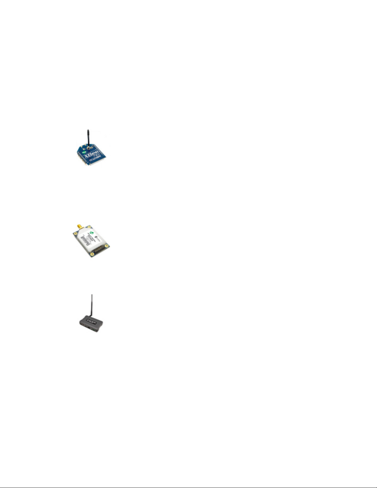
XBee RF modules
XBee is the brand name of a family of RF modules produced by Digi. They are
modular products that make deploying wireless technology easy and costeffective. Digi has made multiple protocols and RF features available in the
popular XBee footprint, giving customers enormous flexibility to choose the best
technology for their needs.
XBee RF modules are available in two form-factors, Through-Hole and Surface Mount, with different
antenna options. One of the most popular features of these modules is that almost all of them are
available in the Through-Hole form factor and share the same footprint.
XTend RF modules
XLR PRO radio solutions
Radio firmware
Radio firmware is program code stored in a radio module's persistent memory that provides the
control program for the device. Digi periodically releases new radio firmware versions to fix bugs or
improve functionality. You may need to add these firmware files to XCTU's radio firmware library. You
can use XCTU to update or change the firmware of a module if, for example, you want to change the
role of a device or you want to use the latest firmware version.
XTend family devices are long-range RF modules produced by Digi that provide
unprecedented range in a low-cost wireless data solution. They were engineered
to provide customers with an easy-to-use RF solution that provides reliable
delivery of critical data between remote devices. These modules transfer
standard asynchronous serial data streams, operate within the ISM 900 MHz
frequency band, and sustain up to 115.2 Kbps data throughput.
The XLR PRO is an ultra long-range, rugged 900MHz radio solution designed for
optimal performance even in the most challenging RF environments. Leveraging
Digi's patent-pending Chirp Spread Spectrum technology, the XLR PRO provides
industry-leading receive sensitivity and interference immunity, making it ideal for
deployments in noisy RF environments like oil fields. The XLR PRO includes 2
Ethernet ports and 1 serial port, enabling wireless data communications
between Ethernet and/or serial devices up to distances of over 90 miles.
XCTU User Guide
16
Page 17
RF concepts and terminology Radio communication protocols
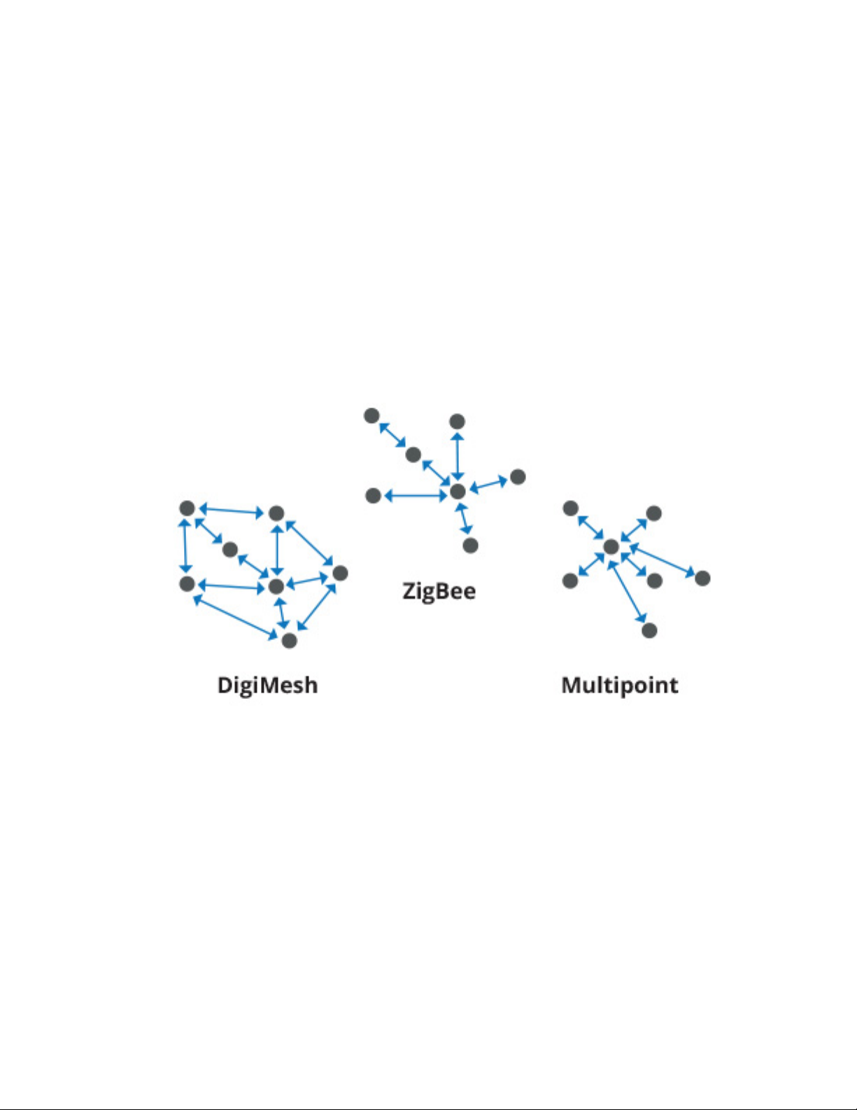
Radio communication protocols
A radio communication protocol is a set of rules for data exchange between radio devices. An RF
module supports a specific radio communication protocol depending on the module and its radio
firmware.
The following is the complete list of protocols supported by the XBee radio modules:
n IEEE 802.15.4
n ZigBee
n ZigBee Smart Energy
n DigiMesh (Digi proprietary)
n ZNet
n IEEE 802.11 (Wi-Fi)
n Point-to-multipoint (Digi proprietary)
n XSC (XStream-compatible)
Not all XBee devices can run all listed communication protocols. The combination of XBee hardware
and radio firmware determines the protocol that an XBee device can execute. For more information
about the available XBee RF modules and the protocols they support, see XBee RF Family Comparison
Matrix.
Radio module operating modes
The operating mode of an XBee radio module establishes the way a user or any microcontroller
attached to the XBee communicates with the module through the Universal Asynchronous
Receiver/Transmitter (UART) or serial interface.
Depending on the firmware and its configuration, radio modules can work in three different operating
modes:
XCTU User Guide
17
Page 18

RF concepts and terminology Radio module operating modes
n Application Transparent (AT) operating mode
n API operating mode
n API escaped operating mode
In some cases, the operating mode of a radio module is established by the firmware version, which
determines whether the operating mode is AT or API, and the AP setting of the firmware, which
determines if the API mode is escaped (2) or not (1). In other cases, the operating mode is only
determined by the AP setting, which allows you to configure the mode to be AT (AP=0), API (AP=1), or
API escaped (AP=2).
AT operating mode
In AT (Application Transparent) or transparent operating mode, all serial data received by the radio
module is queued up for RF transmission. When RF data is received by the module, the data is sent out
through the serial interface.
To configure an XBee module operating in AT, you must put it in command mode to send the
configuration commands.
AT Command mode
When the radio module is working in AT operating mode, you must use the command mode interface
to configure settings.
To enter AT command mode, send the three-character command sequence (usually "+++") within one
second. Once AT command mode has been instigated, the module sends an "OK\r", the command
mode timer is started, and the radio module is able to receive AT commands.
AT command structure
The structure of an AT command is:
AT[ASCII command][Space (optional)][Parameter (optional)][Carriage return]
For example:
ATNI MyDevice\r
If no valid AT commands are received within the command mode timeout, the radio module
automatically exits AT command mode. You can also exit command mode by issuing the CN command:
(ATCN\r)
API operating mode
API (Application Programming Interface) operating mode is an alternative to AT mode. API operating
mode requires that communication with the module be done through a structured interface. In other
words, data is communicated via API frames.
The API specifies how commands, command responses, and module status messages are sent and
received from the module using the serial interface. With API operating mode, you can:
n Configure the XBee module itself.
n Configure remote modules in the network.
n Manage data transmission to multiple destinations.
XCTU User Guide
18
Page 19

RF concepts and terminology API frames
n Receive success/failure status of each transmitted RF packet.
n Identify the source address of each received packet.
Depending on the AP parameter value, the radio module can operate in one of two modes: API (AP=1)
or API escaped (AP=2) operating mode.
API escaped operating mode
API escaped operating mode (AP=2) is similar to API mode except that when working in API escaped
mode, some bytes of the API frame specific data must be escaped. Since XCTU is compatible with both
API and API escaped operating modes, you do not need to manually escape characters.
API escaped operating mode increases the reliability of RF transmission by preventing conflicts with
special characters such as the start-of-frame byte (0x7E). API non-escaped (API=1) operation relies
solely on the start delimiter and length bytes to differentiate API frames. In API escaped mode, on the
other hand, those special bytes are escaped. Since 0x7E can only appear at the start of an API packet,
a module can always "assume" that a new packet has started if 0x7E is received at any time while in
API escaped mode.
Escape characters
When sending or receiving an API frame in API escaped mode, specific data values must be escaped
(flagged) so they do not interfere with the data frame sequence.
To escape a data byte, insert 0x7D and follow it with the byte to be escaped XOR'd with 0x20. The
data bytes that need to be escaped are as follows:
n 0x7E: Frame delimiter
n 0x7D: Escape
n 0x11: XON
n 0x13: XOFF
Note XCTU automatically escapes the appropriate characters when interacting with API escaped
radio modules.
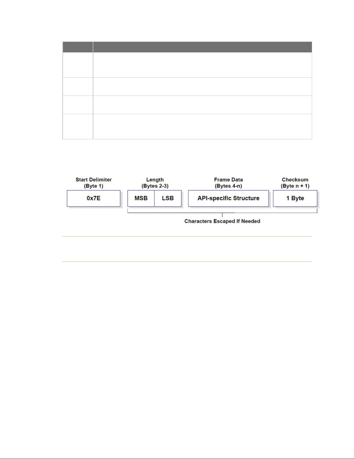
API frames
An API frame is the structured data sent and received through the serial interface of the radio module
when it is configured in API or API escaped operating modes. API frames are used to communicate
with the module or with other modules in the network. An API frame has the following structure:
XCTU User Guide
19
Page 20
RF concepts and terminology AT settings or commands
Field Description
Start
delimeter
Length
Frame
data
Checksum The last byte of the frame. It helps test data integrity and is calculated by taking the
If your module is operating in API escaped operating mode, some bytes in the Length, Frame data, and
Checksum frame fields may need to be escaped. XCTU automatically performs this step and escapes
the appropriate characters. See API escaped operating mode.
The first byte of a frame consisting of a special sequence of bits which indicate the
beginning of a data frame. Its value is always 0x7E. This allows for easy detection of a
new incoming frame.
Specifies the total number of bytes included in the frame data field. Its two-byte value
excludes the start delimiter, the length, and the checksum.
Composed by the API identifier and the API identifier-specific data. The content of the
specific data depends on the API identifier (also called API frame type).
hash sum of all the API frame bytes that came before it, excluding the first three bytes
(start delimiter and length).
Note There are many different types of API frames. You can use the Frames generator tool to learn
the specific data contained within a determined API frame as well as to build and fill any type of API
frame. See Frames generator tool.
AT settings or commands
The firmware running in RF modules contains a set of settings and commands that can be configured
to change the behavior of the module or to perform any action related to it. Depending on the
protocol, the number of settings and their meanings varies, but all XBee RF modules can be configured
with AT commands.
All firmware settings or commands are identified with two ASCII characters. Applications and
documents refer to them as either AT settings or AT commands.
The configuration process of these AT settings varies depending on the operating mode of the RF
module.
Configuring in AT mode
In AT operating mode, you must put the module in a special mode called command mode so it can
receive AT commands. For more information about configuring RF modules working in AT operating
mode, see AT operating mode.
XCTU User Guide
20
Page 21

RF concepts and terminology Local radio modules
Configuring in API mode
To configure or execute AT commands when the RF module is in API operating mode, you must
generate an AT command API frame containing the AT setting identifier and the value of that setting,
and send it to the RF module. See API frames.
Local radio modules
A local radio module is any module added to the device list using the Add a radio module or Discover
radio modules buttons.
XCTU communicates directly with local modules, and they are physically attached to the PC through a
serial or USB port. A local radio module can discover remote modules in the same network if their
protocol is ZigBee or DigiMesh. A local module is configurable if Configuration working mode is active,
and you can communicate with a local module through its console when Consoles working mode is
active.
Remote radio modules
You can locate remote radio modules in the same network as a local module. A remote module is not
physically attached to your computer. Remote modules are displayed in a sub-list under the local
module, and that local module functions as an interpreter; without it, XCTUis unable to communicate
with the remote module. See Discover remote radio modules.
Communication between XCTU and a remote module takes place in two stages: serial communication
from XCTU to the local module, and wireless communication between the local module and the
remote module. XCTU uses the serial port to send a message intended for the remote module, along
with delivery specifics, to the local module. The local module then transmits the message wirelessly to
the remote module.
If the local device containing remote modules is configured in AT (transparent) operating mode, you
cannot configure its remote radio modules due to a protocol limitation. If the local radio module is
configured in API operating mode, you can configure its remote radio modules like any local module.
Since a remote radio module is not physically connected to the PC, it does not have a communication
console in Consoles working mode. For the same reason, you also cannot obtain a remote radio
module's network topology in Network working mode. See Consoles working mode and Network
working mode.
XCTU User Guide
21
Page 22
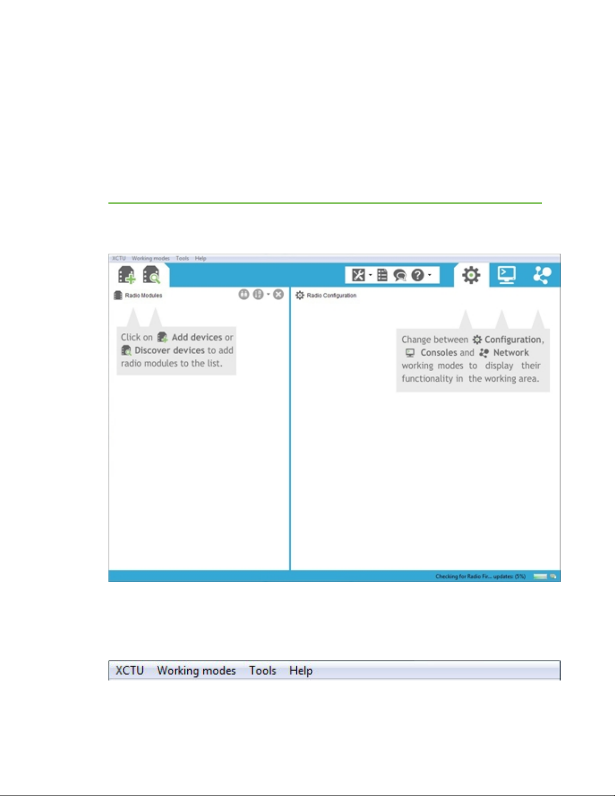
XCTU overview
XCTUis divided into five main sections: the menu bar, main toolbar, devices list, working area, and
status bar.
Menu bar
The menu bar is located at the top of the application. You can use the menu bar to access all
XCTUfeatures, tools, and working modes.
XCTU User Guide
22
Page 23
XCTU overview Main toolbar
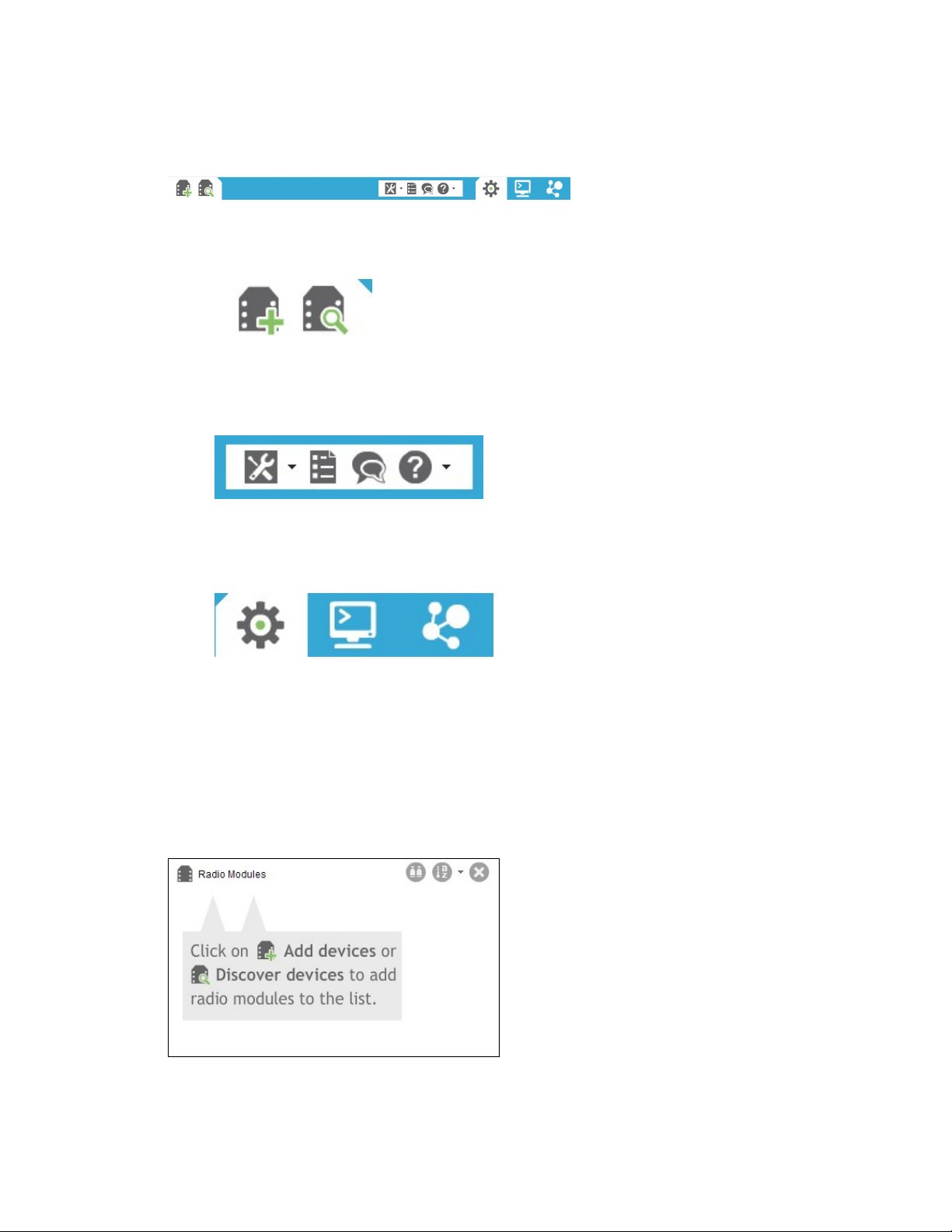
Main toolbar
The main toolbar is located at the top of the application and is divided into three sections.
n The first section contains two icons used to add radio modules to the radio modules list. See
Add radio modules to XCTU.
n The second section contains the static XCTU functionality that does not require a radio module.
This section includes the XCTU tools, the XCTU configuration, the feedback form, and the help
and updates functions. See XCTU tools and Configure XCTU.
n The third section contains tabs corresponding to the three XCTU working modes. To use this
functionality, you must have added one or more radio modules to the list. See XCTU working
modes.
Devices list
The radio modules list, or devices list, is located on the left side of the tool and displays the radio
modules that are connected to your computer. If you know the serial port configuration of a radio
module, you can add it to the list directly. You can also use the discovery feature of XCTU to find radio
modules connected to your PC and add them to the list. See Add radio modules to XCTU.
Depending on the protocol of the local radio modules added, you can also add remote radio modules
to the list using the module's search feature.
XCTU User Guide
23
Page 24
XCTU overview Working area
Working area
The working area is the largest section and is located at the right side of the application. The contents
of the working area depend on the working mode selected in the toolbar. To interact with the controls
displayed in the working area, you must have added one or more radio modules to the list and one of
the modules must be selected.
Status bar
The status bar is located at the bottom of the application and displays the status of specific tasks,
such as the firmware download process.
XCTU preferences
To configure XCTUsettings, click the Preferences button on the XCTU toolbar.
Configuration preferences are grouped into categories listed on the left-hand side of the preferences
dialog box. You can configure settings in the following XCTU categories:
Appearance
You can configure some graphic aspects of the tool and how some elements are displayed.
Field Description
Font size Change all the XCTU texts size in percentage, from 50 to 120%.
Show top bar
menu
Show text on
toolbar actions
Use reduced
toolbars size
Displays an application top bar menu with texts.
Displays the name of the action below each toolbar element for a better
understanding of the meaning of each action.
Changes the size of the application toolbars reducing them.
XCTU User Guide
24
Page 25

XCTU overview XCTU preferences
Automatic updates
Field Description
Automatically find
new updates and
notify me
Update schedule Sets a schedule to search for updates or to update when XCTU is started. If you
Download options Establishes when new updates should download and sets permissions for
When updates are
found
Enables or disables automatic XCTUupdates. Uncheck if you do not want
XCTUto update automatically.
Look for updates on the following schedule
select
the search interval and hour.
whether updates are automatically downloaded.
Sets the frequency of update notification.
, you must also specify
Consoles
Field Description
API
console
AT
console
Configures the maximum number of API frames that can be displayed in the frames log
during a session. When the maximum limit is reached, the session starts overwriting
frames.
Configures the maximum number of bytes that can be displayed during a session. When
the maximum limit is reached, the session starts overwriting bytes.
MadCap:autonum="<span style="color: #84c361;" class="mcFormatColor"><b>Note
</b></span>">If you set high values for maximum API frames and/or ATbytes, you may notice
performance issues in the consoles.
Firmware updates
Field Description
Remote
firmware
update
timeout
Configures the remote firmware update timeout in milliseconds. This value is the
maximum time the application will wait for answers sent by the remote node during
remote firmware update before concluding that there was an error during the process.
Network
You can configure Network view in the Network preferences dialog. The first four options are
common to all networks:
XCTU User Guide
25
Page 26

XCTU overview XCTU preferences
Field Description
Always clear the Network view
Clears Network view before each new network scan.
before starting
Remove nodes if they were not
Removes any nodes not discovered in the last scan.
discovered in the last performed
scan
Stop after scan Sets the number of scans to perform before stopping the
discovery process. A value of '0' means the process will not stop
automatically.
Time between scans Sets the duration of time XCTU waits before starting a new
network scan. The value must be between 0 and 300 seconds.
The remainder of the options are specific to 802.15.4, DigiMesh, and ZigBee network types:
Field Description
Discovery
mode
Sets the method used by the network discovery process.
n Flood: The neighbor discovery process is performed for every node at the
moment it is found. Several discovery processes may be running at the same
time. This method may be faster, but it may also generate a lot of traffic and
saturate the network.
n Cascade: The neighbor discovery process is performed for every node as soon as
the discovery process finishes. Only one discovery process runs at a time. This
method may be slower, but it is likely to generate less traffic.
Neighbor
discovery
Sets the maximum duration, in seconds, the discovery process should spend finding
neighbors of a module. Value must be between 5 and 1800 seconds (30 minutes).
timeout
This timeout is highly dependent on the nature of the network. For DigiMesh, the value
should be greater than the highest NT (Node Discover Timeout) and include enough time
to let the message propagate, depending on the sleep cycle of your devices.
Time
between
Sets the wait time between node neighbor requests. The value must be between 0 and
300 seconds (5 minutes).
requests
For the Cascade method, this is the number of seconds to wait after completion of the
neighbor discovery process of the previous node.
For the Flood method, this is the minimum time to wait between each radio module's
neighbor requests.
Note The Cascade discovery method is recommended for large networks.
Network appearance
You can configure how node links are represented in Network graphic view.
XCTU User Guide
26
Page 27
XCTU overview XCTU working modes
Field Description
Connection default
color
Show colored
connections based
on their quality
DigiMesh / ZigBee
network
Defines the default color of the node's connection lines.
Enables or disables the coloring of node connection lines based on their link
quality.
Enables you to modify the maximum and minimum values and RGB colors for
each quality range. Click in the cell, type the value, and click Enter to change a
value.
Ranges include minimum values but not maximum values. When you change
the minimum value of a quality range, the maximum value of the next range
adopts a corresponding value.
Radio firmware library
You can instruct XCTU to look for new radio firmware when it starts up by checking Automatically
update the XBee Firmware Library each time XCTU is started. If this option is disabled, you can
only check for firmware updates manually.
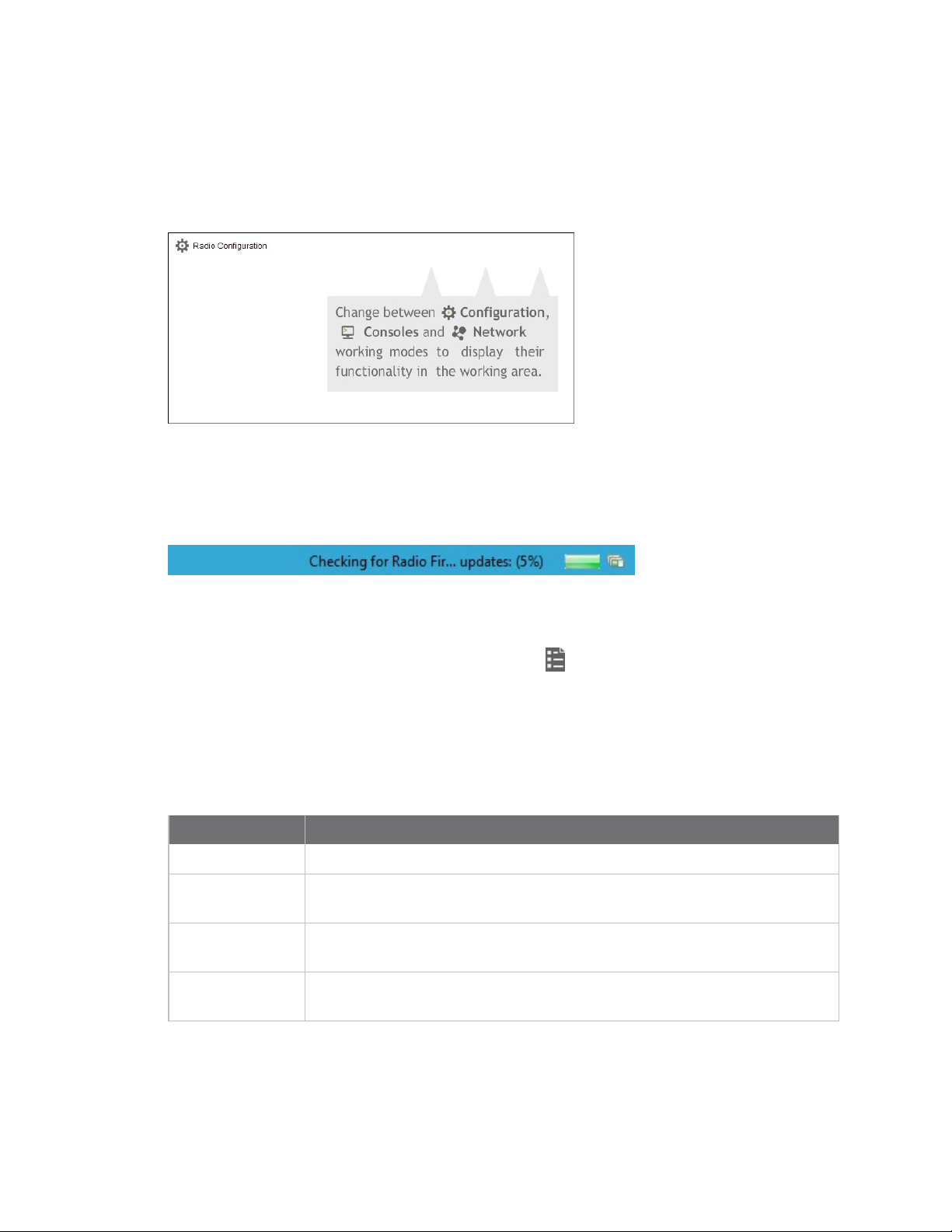
XCTU working modes
XCTU operations are grouped into three working modes—Configuration, Consoles, and Network. The
selected working mode determines which specific operations you can perform with a radio module or
modules in your device list. You can only select one working mode at a time. By default, XCTU launches
in Configuration mode.
Configuration working mode
Use configuration working mode to configure a radio module selected from your device list. See
Configure your modules.
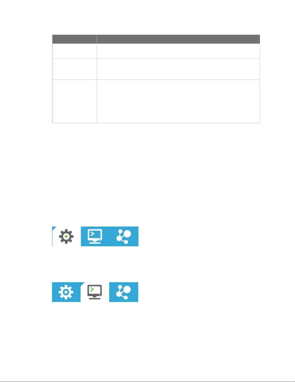
Consoles working mode
Use consoles working mode to interact or communicate with the selected radio module. See
Communicate with your modules.
XCTU User Guide
27
Page 28

XCTU overview XCTU working modes
Network working mode
Use network working mode to discover and visualize the topology and interconnections of your
network. See View your radio network.
XCTU User Guide
28
Page 29

Add radio modules to XCTU
This section describes how to add, discover and organize your radio modules in XCTU.
Add a radio module manually 30
Add a programmable radio module 33
Discover local radio modules 34
Radio module information panel 36
Organize your modules 41
Discover remote radio modules 41
Find radio modules 43
XCTU User Guide
29
Page 30
Add radio modules to XCTU Add a radio module manually
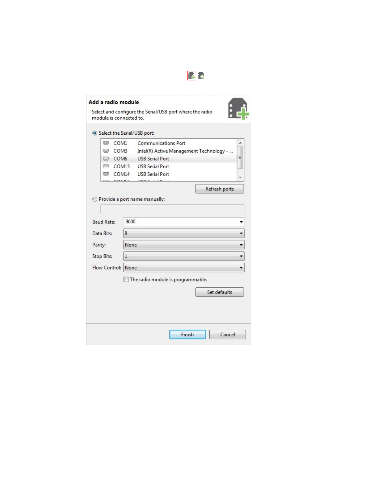
Add a radio module manually
If you know the serial configuration of your radio module, you can add it to the list manually.
1.
Click the Add a radio module button from the toolbar. The Add a radio module
dialog opens.
2. Select the serial port where the radio module is connected (or enter its name manually) and
3. Click Finish to add the radio module to the list of radio modules.
4. If the settings were configured correctly and the radio module was connected to the selected
XCTU User Guide
configure the serial settings of the port.
Note Custom baud rates can only be typed under Windows OS.
port, the module is displayed in the device list. For more information about the device list, see
Radio module information panel.
30
Page 31

Add radio modules to XCTU Add a radio module manually
5. If the settings were configured incorrectly, an Action Required dialog asks you to reset the
module. Reset the module. The action required dialog should close and your module should be
added to the list.
6. If your module could not be found, XCTU displays the Could not find any radio module dialog
providing possible reasons why the module could not be added. To resolve the issue, see
Troubleshooting for XCTU.
XCTU User Guide
31
Page 32

Add radio modules to XCTU Add a radio module manually
Note You can also use the Add a radio module dialog to add programmable radio modules. See Add a
programmable radio module.
XCTU User Guide
32
Page 33

Add radio modules to XCTU Add a programmable radio module
For more information, see Local radio modules and Radio module information panel.
Add a programmable radio module
Some radio module variants are programmable, which means they are able to run applications
written in C. Normally, they are known as Programmable XBee modules and can be identified by a
part number ending in B on the back label.
XBee-PRO modules are often confused with Programmable XBee modules. The -PRO suffix
does not mean that the module is programmable.
To add a programmable radio module:
1.
Click the Add a radio module button from the toolbar. The Add a radio module
dialog opens.
2. Select the serial port to which the radio module is connected (or enter its name manually) and
3. Check the My radio module is programmable setting.
XCTU User Guide
configure the serial settings of the port.
33
Page 34

Add radio modules to XCTU Discover local radio modules
4. Click Finish.
5. Reset your radio module when prompted. The module appears in the device list.
For more information, see Local radio modules and Radio module information panel.
Discover local radio modules
XCTU can discover radio modules that are connected directly to your computer. You can use the
discovery tool if you don't know the serial configuration of your radio module, don't know the port it is
connected to, or want to add multiple modules at once.
1.
Click the Discover radio modules button on the XCTUtoolbar. The Discover radio
modules dialog box opens.
2. Select the serial ports you would like to scan for radio modules. Click Next.
XCTU User Guide
34
Page 35

Add radio modules to XCTU Discover local radio modules
3. Select any port parameters you would like to include in the search process.
Note XCTU displays estimated discovery time in the Set port parameters dialog. Adding more
port parameters to the search increases discovery time.
4. Click Finish to initiate the discovery scan.
XCTU User Guide
A new dialog opens, displaying devices found and estimated time remaining. You can click Stop
to halt the discovery process at any time. For example, you can stop the process if the modules
you were looking for are already found.
35
Page 36

Add radio modules to XCTU Radio module information panel
5. Select the box next to the module(s) you want to add to your device list and click Add selected
devices. The modules appear in the device list.
For more information, see Local radio modules and Radio module information panel.
Radio module information panel
Local radio modules appear as big buttons in the modules list. Each module displays identifying
information about itself.
XCTU User Guide
36
Page 37

Add radio modules to XCTU Radio module information panel
To work with a radio module, you must select it from the list of devices. When you hover over a
module, the background color changes to yellow.
Selecting a radio module refreshes the contents of the working area, displaying the information or
actions you can perform on the selected module. The contents of the working area depend on the
active working mode.
Module Icon
An icon on the left side of the information panel identifies the module type and protocol.
Icon Module type Protocol
XBee ZigBee
XBee DigiMesh (Digi's proprietary protocol)
XBee 802.15.4
XBee Point-to-multipoint
XBee Smart Energy
XCTU User Guide
37
Page 38

Add radio modules to XCTU Radio module information panel
Icon Module type Protocol
XBee ZNet
XBee Wi-Fi
XBee XStream Compatibility
XTend XTend native
XTend DigiMesh (Digi's proprietary protocol)
XLR XLR-PRO native
XLR Module XLR Module
XBee SX
XCTU User Guide
38
Page 39

Add radio modules to XCTU Radio module information panel
Icon Module type Protocol
XBee Cellular
XBee Thread
Each icon may contain a small image in the lower-right corner that identifies the role of that module
within its network:
Icon Description
Coordinator
Router
End device
Buttons along the right-hand side of the module information panel perform actions on the selected
module:
Button Name Description
Remove Removes the radio module from the list of devices. Also removes the
associated communication console and network view of that module.
Removes the local module and any associated remote modules.
Search
Expand/collapse Expands and collapses the remote radio modules list.
Discovers remote radio modules in the same network. Dependent on
radio module protocol. Performs an SSID discovery for Wi-Fi modules,
and for any other protocol performs a discovery of remote radio
modules. See Discover remote radio modules and Active scan.
New firmware indicator
When a radio module is not running the latest firmware version it is able to run, the New Firmware
control displays next to the name label for the information panel.
XCTU User Guide
39
Page 40

Add radio modules to XCTU Radio module information panel
This control indicates that there is a newer firmware version that can be flashed in the radio module.
If you click New Firmware, the Update firmware dialog is automatically opened for that radio
module. All of the available firmware versions for the radio module are listed in the dialog.
Remove a radio module
Click Remove to remove a selected radio module from the list of devices. Removing a module
from the list also disables the associated communication console and network view of the module.
Note Clicking the Remove button of a remote module removes only that radio module from the sub-
list of remote modules. Click the Remove button of a local module with a sub-list of remote modules
removes the local module as well as all of its remote modules.
Expand/Collapse radio modules list
If the protocol of the radio module is ZigBee or DigiMesh and you have found remote modules in the
same network, you can use the expand/collapse button to expand or collapse the list of remote
modules under the local device.
Note This button is only enabled for local radio modules.
XCTU User Guide
40
Page 41

Add radio modules to XCTU Organize your modules
Module information box
When you hover over the icon, XCTU displays additional information about the selected module,
including module type, family, protocol, device type, firmware, and hardware.
Organize your modules
The Radio Modules view contains a toolbar with options to manage radio modules in the list. These
options are only enabled when the list contains at least one radio module.
Find radio modules
Click the Find radio modules button to find local and remote radio modules in your list. For
details, see Find radio modules.
Sort radio modules
Radio modules are displayed in the order in which you added them to XCTU. Click the Sort radio
modules list button to sort radio modules by name, function, serial port, or MAC address. Or
you can select a specific device and move it up/down in the list.
Note The sorting feature affects both local and remote radio modules.
Clear radio modules
Click Clear radio modules list to remove all discovered modules from the radio modules list.
For more information, see Local radio modules and Remote radio modules.
Discover remote radio modules
You can execute a discovery process to locate remote radio modules in the same network as the local
(selected) module. To discover remote modules:
1. Select a module from your device list. If you do not have any modules in the list, see Add a radio
XCTU User Guide
module manually or Discover local radio modules.
41
Page 42

Add radio modules to XCTU Discover remote radio modules
2.
Click the Discover radio nodes in the same network button . As XCTU discovers new
remote radio modules, they appear in the discovery process dialog box.
3. Click Stop to halt the discovery process at any time.
4. Check the box next to the module(s) you want to add to your device list and click Add selected
devices. The discovered remote modules appear in the list of remote modules.
Note XBee Wi-Fi modules do not support the remote radio modules discovery feature. Instead, they
can look for access points.
For more information, see Remote radio modules.
XCTU User Guide
42
Page 43

Add radio modules to XCTU Find radio modules
Find radio modules
To find local or remote radio modules, you must have already discovered the network they are on. You
can then use the Find radio modules search box to find radio modules by MAC address, name, network
address, and other search expressions.
1.
On the Radio Modules toolbar, click the Find radio modules button.
The Find radio modules search box appears.
2. Enter your search expression to find one or more modules.
For a list of search prefixes and wildcards, as well as sample searches, see Search expressions.
3. Press Enter.
The background color of the search box and search icon indicates status. Yellow indicates
matches found by XCTU, and red indicates no matches. Modules found along the list are also
highlighted in yellow.
Search expressions
You can enter the following search prefixes in the Find radio modules dialog box.
Search prefix Search by
MAC: (or no prefix) MACaddress
XCTU User Guide
43
Page 44

Add radio modules to XCTU Find radio modules
Search prefix Search by
SH: Serial Number High
SL: Serial Number Low
NI: Node Identifier (only available in 802.15.4 and DigiMesh)
MY: 16-bit Network Address (only available in 802.15.4 and ZigBee)
You can also use a wildcard if you do not want to specify the entire parameter or if you want to find
more than one node.
Wildcard Equals
* any string
? any character
\ escape for literals (i.e. *, ?, or \)
Sample searches:
n To search for a module with node identifier (NI) "NODE1" and network address (MY) 0831,
enter
NI:NODE1, or MY:0831
n To find all nodes whose MAC starts with 00 and ends with B, enter
MAC:00*B
XCTU User Guide
44
Page 45

Configure your modules
This section describes how to use Configuration working mode to configure your modules and change
application settings once you have added a radio module or modules to your list of devices.
Configuration working mode 46
Read radio module configuration 54
Write module settings 54
Load default firmware settings 54
Update firmware 55
Work with configuration profiles 57
Search for a firmware setting 67
Configure remote modules securely 67
Configure a Wi-Fi access point 71
Enable and configure Bluetooth 73
View firmware release notes 74
XCTU User Guide
45
Page 46

Configure your modules Configuration working mode
Configuration working mode
When you launch XCTU, Configuration working mode opens as the default operating mode.
The Configuration working mode allows you to configure any radio module that has been added to
your device list. When you select a module from the list, XCTU loads the firmware information of the
selected radio module and displays the firmware settings in the working area. It automatically reads
the values and fills in the fields.
Configuration toolbar
The Configuration toolbar presents the configuration actions you can perform with the selected radio
module and firmware settings.
Button Name Description
Read module
settings
Write module
settings
Load default
firmware
settings
Update
firmware
Reads the firmware settings for the selected radio module.
Writes new firmware values to the selected radio module.
Loads the default firmware values on to the selected radio module
but does not write them.
Opens the Update the radio module firmware dialog, displaying
available compatible firmware for the selected radio module.
XCTU User Guide
46
Page 47

Configure your modules Configuration working mode
Button Name Description
Load/save
configuration
profile
Search Enables you to search firmware settings by AT parameter.
Expand/collapse
settings
Opens the Load configuration profile or Save configuration
profile dialog.
Expands or collapses all firmware settings sections.
Firmware information panel
The firmware information panel is located below the Configuration toolbar and displays information
about the firmware running in the selected radio module.
Firmware settings
XCTU displays firmware settings of the radio module below the firmware information panel. They are
divided into sections or categories with a short description in each. Read-only settings are displayed
with a gray label.
XCTU User Guide
47
Page 48

Configure your modules Configuration working mode
The following table provides descriptions for the setting controls.
Field Description
Information
button
Clicking the information button displays a short description of the setting, including
the default value and the valid range, if the setting is numeric.
AT
parameter
Setting
name
Displays the associated AT parameter of the setting. Some settings, such as actions,
may not have an associated AT parameter.
In the example above, the ATparameter is SD.
Displays the name of the setting.
In the example above, the setting name is Scan Duration.
XCTU User Guide
48
Page 49

Configure your modules Configuration working mode
Field Description
Setting
configuration
control
Units label
Value
calculator
icon
Contains the text box or combo box where the setting value must be entered or
configured. You can hover over the text box of a numeric setting to display the valid
range for that setting. Always enter numeric values in hexadecimal format (without
the '0x' prefix), unless the hover text indicates that an ASCII value is required.
If the setting is configured with an invalid value, an explanation for the error
appears.
Displays the units of measure for that setting. Not all settings have a units label.
In the example above, the unit is exponent.
Clicking the value calculator icon launches a time or bitfield calculator for numeric
settings that are difficult to compute. The content of the calculator panel depends
on the setting.
Refresh and
write
buttons
Setting status
XCTU delineates the status of each setting with background color and/or the color of a triangle
located next to the setting value. These are the possible statuses of a setting:
XCTU User Guide
Clicking the refresh button or write button allows you to read or write the
value of the setting. Some settings, such as the read-only settings, do not have a
write button.
Green triangle The value of the setting has changed but it has
not been written in the radio module yet.
49
Page 50

Configure your modules Configuration working mode
Blue triangle The value of the setting is written in the radio
module but is different from the default value.
Gray background The value of the setting is written in the radio
module and matches the default value.
Yellow background
Indicates that the setting is highlighted
because it has been found using the Search
parameter control.
Red background The value of the setting is not valid.
Setting types
There are different kind of settings that you can configure in a radio firmware. Depending on the
setting type they display different controls and options.
n Numeric settings: These settings must always be configured with a numeric value in
hexadecimal format (without the '0x' prefix). Hovering over the text box of a numeric setting
displays the valid range for the setting. There are several types of settings:
n Text settings: Text settings are very similar to the numeric settings, but they can be
configured with hexadecimal or ASCII characters. If you hover over the text box of a text
setting, a dialog displays the minimum and maximum characters and whether they must be an
ASCII or hexadecimal value.
n Combo settings: A combo box displays all the possible values of the setting with symbolic text,
n Read-only settings: These settings cannot be modified. They can only be read from the radio
n Action settings: These settings can be neither read nor written. The main purpose of the
XCTU User Guide
to help you to choose the correct option.
module and their values are displayed in a label.
action settings is to execute a task or process in XCTU that implies some interaction with the
50
Page 51

Configure your modules Configuration working mode
radio module. To learn more about the Action settings see the Special functions topic.
Special functions
Some settings within XCTU cannot be read or written. Instead, they execute tasks or processes in
XCTU related to interaction with the radio module. The processes that these settings execute are
called special functions. At this time, XCTU has two special functions: Active scan and Bluetooth
Authentication.
Active Scan
The Active Scan function discovers and configures the access point for an XBee Wi-Fi module.
When you click the Active Scan button, XCTU reads the SSID configuration of the Wi-Fi module. If the
module has an SSID already configured, you need to clear the configuration and perform a new SSID
discovery. If the SSID configuration is empty, the nearby SSIDs are displayed in a new dialog.
The dialog displays all the nearby access points as well as their security protocols and signal quality.
Select the Access Point you want the Wi-Fi module to connect to and, if necessary, configure the
password of the Access Point. The Access Point settings also have a check box that allows you to
permanently save the SSID configuration in the Wi-Fi module. If you uncheck this option, the next time
you reset the module the SSID configuration is cleared.
XCTU User Guide
51
Page 52

Configure your modules Configuration working mode
Click Connect to connect the Wi-Fi module to that Access Point and refresh the settings of the radio
module.
Enable BLEand configure the BLEpassword
The Bluetooth Authentication function allows you to configure the security parameters of your XBee
device with Bluetooth Low Energy (BLE)support. This step is mandatory if you want to enable
Bluetooth on the module.
XBee BLE security is based on the Secure Remote Password protocol. When you click the Configure
button, XCTU displays a dialog asking you to either:
1. Type a password, which you are asked for when you connect to the XBee via Bluetooth Low
Energy.
2. Enter a random salt and a password verifier generated from a password and that salt (as
specified in the SRP protocol).
CAUTION! Only use the advanced configuration if you are familiar with the SRP protocol. You
must know the password which originated the verifier since you will be asked for it when you
connect to the XBee via BLE.
XCTU User Guide
52
Page 53

Configure your modules Configuration working mode
When you enter the password or the salt/verifier combination, click OK to save the settings to the
module.
For more information about Bluetooth security, see the user guide for your XBee device.
XCTU User Guide
53
Page 54

Configure your modules Read radio module configuration
Read radio module configuration
You can refresh a radio module's firmware settings once you have added the module to your device
list. To read a module's configuration settings:
1.
Switch to Configuration working mode .
2. Select a radio module from the device list. XCTU displays the current firmware settings for that
module.
Note If the selected module is remote and the Remote AT Command password (KZ) is set, you
may be asked to enter that password in order to access the module configuration.
3.
From the configuration toolbar, click the Read module settings button to refresh the
selected radio module's firmware settings.
Write module settings
You can configure a radio module's firmware settings once you have the module to your device list. To
configure a radio module:
1.
Switch to Configuration working mode .
2. Select a radio module from the device list. XCTU displays the current firmware settings for that
module.
Tip To refresh the selected radio module's firmware settings, click the Read module settings
button on the configuration toolbar.
Note If the selected module is remote and the Remote AT Command password (KZ) is set, you
may be asked to enter that password in order to access the module configuration.
3. Change the value of the setting or settings to be configured.
4.
Click the Write module settings button to write any newly configured firmware values to
the module.
Load default firmware settings
You can load default radio firmware settings in a module in your device list.
1.
Switch to Configuration working mode .
2. Select a radio module from the device list. XCTU displays the current firmware settings for that
module.
3.
On the Configuration toolbar, click the Load default firmware settings button to load the
default values established by the firmware.
4. Firmware settings are loaded but not written to the radio module. In order to write them in
the module, click the Write module settings button on the toolbar.
XCTU User Guide
54
Page 55

Configure your modules Update firmware
Update firmware
You can use XCTU to update a module's radio firmware.
1.
Switch to Configuration working mode .
2. Select a radio module from the device list.
3.
Click the Update firmware button . A dialog box appears displaying the available and
compatible firmware for the selected module.
4. Choose the firmware family, function, and version.
5. Click Update. A dialog box displays update progress. You can click the Show details button to
XCTU User Guide
Note If you do not remember the firmware version that is currently installed in your radio
module, click Select current to automatically select it.
view a detailed progress log, and Hide details to hide it.
Note During the firmware update process, XCTU attempts to obtain the module information
again, as some critical settings such as the operating mode could have changed. If the
Maintain current module configuration setting is checked, XCTU writes the old configuration
to the module and then reads the setting's values.
55
Page 56

Configure your modules Update firmware
Cellular modem firmware updates
When you update the firmware of an XBee Cellular device, XCTU may need to update the modem
firmware. This process is completely transparent, but XCTU requires an internet connection to
download the modem firmware.
Note The system prompts you for confirmation when the device requires a modem firmware update,
as this process may take up to 30 minutes in old devices.
For newer XBee 3 Cellular devices (LTE CAT 1 and LTE-M/NB-IoT), this process is done over USB and is
much faster, but only works in Windows. You need to have the appropriate USB drivers installed on
your computer and either a Digi XBIB-CU-TH development board or your own hardware that makes a
USB port available to a PC. Before starting the update, XCTU asks you to connect the USB micro-B
cable to the USB Direct Connect port and set the switches to OFF.
Remote firmware updates
You can use XCTU to perform firmware updates on remote modules because once you add a remote
module to XCTU's device list, the update process is exactly the same whether you are updating a local
module or a remote module. To perform a remote firmware update, the local module must be working
in API or API escaped operating mode.
Remote firmware updates can be performed on the following radio modules:
n XBee/XBee PRO SX
n XLR Module
n XBee/XBee PRO 802.15.4 (S2C module versions only)
n XBee/XBee-PRO DigiMesh 2.4 (S2C module versions only)
n XTend RF Module Family (SX module versions only)
n XLR PRO Radio Solution
n XBee/XBee-PRO ZB and Programmable XBee-PRO ZB
n XBee/XBee-PRO ZB SMT and Programmable XBee-PRO ZB SMT
n XBee-PRO 900HP and Programmable XBee-PRO 900HP
n XBee 865LP and Programmable XBee 865LP
XCTU User Guide
56
Page 57

Configure your modules Work with configuration profiles
n XBee 868LP SX
n XBee3 (Zigbee, DigiMesh 2.4, and 802.15.4)
Note If something goes wrong during an over-the-air firmware update on a remote module—for
example, communication is lost because the remote device is disconnected—you must perform a
manual recovery. See Recover a radio module.
Bootloader updates
Some firmware versions require a specific bootloader version in order to work properly. The
bootloader is the software running in the module that, among other things, launches the firmware as
soon as the module boots.
The bootloader update takes place during the firmware update process. If the firmware to be flashed
requires a bootloader update, XCTU updates the bootloader first and then the module's firmware.
Note The system prompts you for confirmation when the firmware requires a bootloader update, as
this process erases the configuration of the module. You must accept it in order to continue with the
firmware update process. If you decline the bootloader update, the overall firmware update process is
canceled.
Work with configuration profiles
A configuration profile is a snapshot of a specific radio firmware configuration, including firmware,
settings values and other configuration information. XCTU allows you to create, inspect and and apply
configuration profiles to the radio module. This feature is useful in a production environment when you
need to set the same parameters on multiple radios.
These are the actions that XCTU allows you to perform related to configuration profiles:
n Create a configuration profile
n Apply a configuration profile
n Load and edit a configuration profile
Create a configuration profile
You can create a configuration profile from two different places within XCTU. You can either create a
profile based on the configuration of an XBee device or create a profile from scratch.
Create a profile based on the configuration of an XBee device
The first way to create a profile is to create a representative model upon which to base the
configuration profile and then save the profile. To do this, you need to have a radio module added in
XCTU.
Note You only need to configure the values; it is not necessary to write the settings to the module.
To do so follow these steps:
1.
2. Select a radio module from the device list.
3. Configure the radio module with your desired values.
XCTU User Guide
Switch to Configuration working mode .
57
Page 58

Configure your modules Work with configuration profiles
4. Click the Configuration profile's drop-down menu on the Configuration toolbar and select
Create configuration profile.
5. Create profile wizard displays.
Create a new profile from scratch
It is also possible to create a new profile without any pre-configured firmware or settings. To create a
new profile from scratch:
1. Launch the Profile editor tool by selecting Profile Editor from the Tools drop-down menu on
the main toolbar.
2. Click the Create button from the toolbar. The Create profile wizard displays.
In either case, the Create profile wizard displays. Follow the steps provided there to create the
configuration profile.
n Create profile wizard
Create profile wizard
The Create profile wizard allows you to create a new configuration profile to be used later in XCTU or
other XBee management applications. You can access this wizard either from the Profile editor tool
or from the toolbar of the Configuration working mode view. See Create a configuration profile for
more information.
Once the wizard is open, follow these steps to configure and create a new configuration profile:
1. In the first page of the profile you can set the profile description and the configuration
features:
a. Flash radio firmware. With this setting you can decide if the profile will flash the firmware
in the XBee module or not. If you check it you can choose one of the following flash options:
i. Flash if firmware is different. Firmware is flashed in the module only if the firmware
version that the module is running is different from the one specified in the profile.
ii. Flash always. Firmware is always flashed regardless of the version running in the
device.
b. Reset module to factory defaults before applying settings. Check this option if you
want to reset the XBee module to its default values (equivalent to send an RE command)
before configuring the firmware parameters.
c. Format existing file system. You can check this option to format the existing file system
of the device when applying the profile. If you choose to flash a new file system too, the
format step will be performed before flashing the new file system.
XCTU User Guide
58
Page 59

Configure your modules Work with configuration profiles
d. Flash a new file system. With this setting you can attach a file system to the profile that
will be transferred to the XBee module when applying the profile. Notice that the Format
existing file system option is automatically checked when you check this one.
e. Use custom scripts. When creating a profile with this setting, you can indicate a pre-
processing script or a post-processing script, or both to be used when programming
devices with XBee Multi Programmer.
n This feature allows you to write your own scripts using your own libraries or the ones
provided by Digi to interact with your XBee devices.
l Pre-processing script: This script is run before applying the profile to the XBee
device. Use it to read specific information of your device before applying the
configuration profile.
l Post-processing script: This script is run after applying the profile to the XBee
device, as a final step. With it you can set specific configurations to your devices, for
example, use it to set a different Node Identifier on each of your XBee devices.
Note This feature can only be used by XBee Multi Programmer. Other tools will skip
the custom scripts steps when applying a profile to an XBee device.
XCTU User Guide
59
Page 60

Configure your modules Work with configuration profiles
2. Click Next to configure the XBee firmware of the profile. Choose the desired firmware
selecting its corresponding properties:
a. Product family of the firmware.
b. Function set that determine the functionality of the firmware (mode of operation, special
sensor and adapter settings, and so forth).
c. Firmware version. The most recent firmware version appears at the top of the list.
Note If you accessed the wizard from the Configuration working mode, the firmware should already
be selected with the firmware that the XBee device is running.
3. Click Next to configure the XBee firmware parameters. This page displays all the firmware
XCTU User Guide
settings split in categories. Each configurable setting has a checkbox at the left side. Check
and edit the value of those settings you want to be configured by the profile.
60
Page 61

Configure your modules Work with configuration profiles
Note If you accessed the wizard from the Configuration working mode, the firmware settings
should be already checked and selected with the ones configured in the XBee device.
4. Click Next to set a file system to the profile. If the profile is configured to attach a file system—
the first page of the wizard—you can use the Browse button to specify it here. Updating the file
system of remote devices must be performed through a remote file system image. So, if the
target firmware supports it and you want the profile to flash a file system in remote devices,
you must check the Attach a remote file system image option and then specify the image
using the corresponding Browse button. If the target firmware does not support OTA file
system updates, the Attach a remote file system image option will not be displayed.
Note If you do not know how to obtain a remote file system image, see Update the file system of
remote devices.
XCTU User Guide
61
Page 62

Configure your modules Work with configuration profiles
5. Click Next to set the pre and/or post scripts to be executed when flashing the profile with
XBee Multi Programmer.
This feature allows you to run a script/program before and/or after applying a profile to the
target device. This wizard page is split into two sections, one for the pre-processing script, and
the other for the post-processing script. Depending on whether you want to run the preprocessing script or the post-processing script, or both, fill in the appropriate information on
each section respectively. Each section contains fields to indicate:
a. The command to execute. Use whatever scripting language you want, but make sure it
can be used by the machine that applies the profile. For example, if the command to run
is:pyhton set_node_id.py, it is mandatory that the correct Python interpreter is installed
and accessible in the machine that applies the profile.
b. The maximum timeout for the script. By default, it is five minutes. This is the maximum
time XBee Multi Programmer should wait for the script to finalize its execution. When this
time has passed, if the script has not finished, XBee Multi Programmer will assume your
program got locked, and will stop the execution of the script returning a Timeout
Exception. This parameter is specified in minutes, and its valid range of values goes from 1
to 300 minutes.
c. Optionally, the folder containing the script/program to run. This is a directory
containing the script to be run and all of the resources it might need during its execution. It
XCTU User Guide
62
Page 63

Configure your modules Work with configuration profiles
is not mandatory to attach any script to the profile, as long as it is accessible by the
machine that applies the profile. To indicate the script/program to run, use one of the
following:
n Attach the folder that contains the script to the profile. To do so, click the Browse
button of the corresponding section. Select the complete folder that contains your
script—this will be the execution path. It does not matter that in order to run the script
needs multiple files, as long as they are all included in the selected folder. If external
resources are required by the script, make sure they are properly handled within your
script, or include them in the same folder as your script so they are attached to the
profile.
n Use absolute paths to call a script that already exists in the machine that will apply the
profile. The first field of each section (the command) can be called using absolute paths.
Bear in mind that such script needs to handle all paths in an absolute manner, as well.
In this case, the execution path will be the path where the XBee Multi Programmer was
installed.
XCTU User Guide
63
Page 64

Configure your modules Work with configuration profiles
6. When you have all the profile parameters configured, click Create profile to open the save file
7. Select the destination path and click Save to create the profile.
XCTU User Guide
dialog.
64
Page 65

Configure your modules Work with configuration profiles
Apply a configuration profile
Follow these steps to apply a configuration profile to an XBee device:
1.
Switch to the Configuration working mode .
2. Select a radio module.
3.
Click the Configuration profiles drop-down menu on the Configuration toolbar and select
Apply configuration profile.
An Open file dialog appears, asking for the configuration profile file to load.
4. Locate the configuration profile (an XPRO file) and click Open. Depending on the firmware
compatibility with your radio module and the firmware flash action configured in the profile, a
dialog box may appear:
n If the firmware of the configuration profile does not match the firmware running in the radio
module but is compatible with the module and the profile is configured to always flash the
firmware or flash when it is different, click Yes to update the module's firmware so the profile
will load correctly.
n If the firmware of the configuration profile is not compatible with the radio module, click Yes to
open the profile in the Profile editor tool.
XCTU User Guide
65
Page 66

Configure your modules Work with configuration profiles
n If the firmware of the configuration profile matches the firmware running in the radio module
but the profile is configured to always flash the firmware, click Yes to update the module's
firmware so the profile will load correctly.
n If the firmware of the profile you are loading and the firmware running in the radio module
match or the profile is configured to don't flash the radio firmware, XCTU applies the settings
saved in the profile to the radio module.
Load and edit a configuration profile
Note This topic explains how to load a configuration profile to inspect and modify it using the Profile
editor tool. For an explanation of how to apply a configuration profile in a module, see Apply a
configuration profile instead.
Follow these steps to load and inspect a configuration profile:
1. Launch the Profile editor tool by selecting Profile Editor from the Tools drop-down menu
on the main toolbar.
2. Click Load from the toolbar.
3. Look for the configuration profile (xpro extension) you want to load. Click Open.
4. The Profile editor tool loads the profile information and displays it along the different tabs of
the view:
a. Configuration. Contains the configured profile features and description.
b. XBee firmware. Displays the product family, function set and version of the firmware
corresponding to the profile.
c. Firmware settings. Contains the list of firmware settings configured for the profile.
d. File system. If the profile is configured to include a file system, this tab displays its
structure.
e. Custom scripts. Displays the pre and post-processing custom scripts commands, timeout
and structure for each script, if this profile is configured to use custom scripts.
If you want to modify the firmware, change any setting you want and click Save. You can then choose
between one of the following Save options:
n Save profile. Overwrites the loaded profile.
n Save as new profile... Allows you to save a new profile with the changes made in the loaded
XCTU User Guide
one.
66
Page 67

Configure your modules Search for a firmware setting
Search for a firmware setting
The configuration toolbar includes a search box. To search for a firmware setting in the list of settings,
search for the AT parameter associated with the setting. If the setting is found, it is highlighted in
yellow.
Configure remote modules securely
New XBee firmware versions allow you to add extra protection layers to encrypted networks in order
to prevent an intruder from hijacking a device and making changes in the network and to protect
against external man-in-the middle attacks. You can use different protection methods depending on
the XBee product:
n Secure session (XBee 3 only)
n Secure Remote Commands (XBee SX only)
Secure session
A secure session is a secure connection between two XBee nodes of a network—a server and a
client—where the pair can send and receive encrypted data that only they can decrypt. In a secure
session, the XBee devices can act as client or server:
n Client. The device that is attempting to log in and send secured data/commands.
n Server. The device that is being logged into and will receive secured data/commands.
Secure sessions provide a way to password-protect communication between two nodes on a network
above and beyond the security of the network itself. With secure sessions, a device can 'log in', or
create a session with another device that is encrypted and only readable by the two nodes involved.
By restricting certain actions—such as remote AT commands or OTA firmware updates—to be only
allowed over one of these secure sessions, you can make it so access to the network does not allow
network configuration.
Note To learn more about this feature and how it works, refer to the user guide for your XBee RF
module.
XCTU User Guide
67
Page 68

Configure your modules Configure remote modules securely
Enable and disable the secure session
The Secure session feature is enabled by default in the firmware, but you can disable it with the SR
(SRP Secure Session disable) setting in order to allow the host MCU to play the authentication role
instead:
n Bit 0 - Disable SRP authentication on the client side of the connection.
n Bit 1 - Disable SRP authentication on the server side of the connection.
Set all other option bits to 0.
Set the password of a secure session
For a device to act as a secure session server, it must have a password configured. The password is
configured on the server in the form of a salt and verifier used for the SRP authentication process. The
salt and verifier values are calculated when you set your password.
Follow these steps to configure the secure session password of the server:
1.
Switch to the Configuration working mode .
2. Select a Secure Session capable radio module from the Radio Modules list.
3. Browse the Secure Session Authentication setting in the list of settings (inside the Secure
Session category) and click the Configure button. The Configure Secure Session
Authentication dialog appears.
XCTU User Guide
68
Page 69

Configure your modules Configure remote modules securely
4. In the Password field, type the password for the device. As you type, the Salt and Verifier fields
Configure the secured features
Secured access to the different features of the XBee device is enabled by setting bits of the SA
(Secure Access Options):
n Bit 0 - Unused.
n Bit 1 - Remote AT Commands.
n Bit 2 - Over-the-air file system updates.
n Bit 3 - Over-the-air firmware updates.
n Bit 4 - Serial Data.
Set all other bits to 0.
XCTU User Guide
are automatically calculated and populated in the dialog as shown above. This is the password
that will be requested when you try to configure the device remotely.
69
Page 70

Configure your modules Configure remote modules securely
Start a secure session
XCTU detects automatically if a secure session needs to be established with a remote XBee device in
order to configure or communicate with it. When this happens, XCTU displays the Secure session
password dialog, where you have to enter the password configured in the remote XBee device you
want to communicate with.
Secure Remote Commands
XBee SX devices include a feature in the firmware called Secure Remote Commands that allows you to
protect an XBee device on the network from external configurations.
To enable the secured remote configuration, set a password with the KZ command. To do so, type the
old password (0 by default), followed by a blank space and the new password. For example, if your
password is 1234 and you want to change it to 7a$b3l1, you should type:
1234 7a$b3l1
After the password has been set, the Password required dialog appears when you try to configure a
remote device and the password is set on your local one (KZ is not set to 0). The same dialog appears
if you perform a range or throughput test with a remote device.
You must enter the password and click OK before you can configure the device.
XCTU User Guide
70
Page 71

Configure your modules Configure a Wi-Fi access point
Note To learn more about this feature and how it works, refer to the user guide for your XBee RF
module.
Configure a Wi-Fi access point
The Active scan special function discovers and configures the access point for the XBee Wi-Fi module.
The feature is only enabled for Wi-Fi modules.
1.
Switch to Configuration working mode .
2. Select a Wi-Fi-enabled radio module from the device list.
3. Click the Active scan button. XCTU reads the SSID configuration of the Wi-Fi module.
n If the module already has an SSID configured, click Yes to clear the configuration and
perform a new SSID discovery.
n If the SSID configuration is empty, XCTU displays all nearby access points as well as
XCTU User Guide
71
Page 72

Configure your modules Configure a Wi-Fi access point
their security protocols and signal quality.
4. Select the SSID you want the Wi-Fi module to connect to.
For S6 Wi-Fi modules, the table displays the following fields:
Field
SSID name Name of the access point
RSSI (dBm) RSSI of the access point (negated hex value)
Security Security type of the access point
Quality Link quality (based on the RSSI) with the access point
For S6B Wi-Fi modules, the table displays the following fields
Field
SSID name Name of the access point
Description
Description
XCTU User Guide
72
Page 73

Configure your modules Enable and configure Bluetooth
Field
Link margin (dBm) Signal strength in dBm above sensitivity
Security Security type of the access point
Channel Channel number in use by the access point
Quality Link quality (based on the link margin) of the access point
5. If necessary, enter the password of the access point.
6. If you would like to retain the SSID configuration for future use, check Save the SSID
configuration in the module.
7. Click Connect to connect the Wi-Fi module to that access point and refresh the settings of the
radio module.
Description
Enable and configure Bluetooth
Some of the latest XBee3 modules support Bluetooth Low Energy (BLE) as an extra interface for
configuration. If you want to use this feature, you have to enable BLE. You must also enable security by
setting a password on the XBee device in order to connect, configure, or send data over BLE.
Before you begin, you should determine the password you want to use for BLEon the XBee device and
store it in a secure place. Digi recommends a secure password of at least 8 characters and a random
combination of letters, numbers, and special characters. Digi recommends using a security
management tool such as LastPass or Keepass for generating and storing passwords for many
devices.
The salt and verifier values are calculated when you set your password.
1.
Switch to Configuration working mode .
2. Select a BLE compatible radio module from the device list.
3. Select Enabled[1] from the BT Bluetooth Enable command drop-down.
4.
Click the Write setting button . The Bluetooth authentication not set dialog appears.
5. Click Configure in the dialog. The Configure Bluetooth Authentication dialog appears.
6. Type a password or a salt/verifier combination (as specified by the Secure Remote Password
protocol—only for advanced users). When you connect the XBee device via BLE, it asks for this
password (or the one that generated the verifier).
XCTU User Guide
73
Page 74

Configure your modules View firmware release notes
7. In the Password field, type the password for the device. As you type, the Salt and Verifier fields
are automatically calculated and populated in the dialog as shown above. This password is
used when you connect to this XBee device via BLE using the XBee Configurator app.
For more information about Bluetooth, see the user guide for your XBee device.
View firmware release notes
XCTU allows you to review the release notes of some of the firmware it hosts.
1.
Switch to Configuration working mode .
2. Select a radio module from the device list.
3.
Click the Update firmware button . The Update firmware dialog appears, displaying the
available compatible firmware for that module.
XCTU User Guide
74
Page 75

Configure your modules View firmware release notes
4. Select the firmware family, the firmware function, and the firmware version. If the selected
firmware has release notes, the View Release Notes button below the
firmware list is enabled.
5. Click View Release Notes. A new window displays the release notes for the selected firmware.
Note You can also access the release notes of firmware via the XBee recovery tool and the Firmware
explorer tool.
XCTU User Guide
75
Page 76

Communicate with your modules
This section describes how to use Consoles working mode to communicate with your modules once
you have added a radio module or modules to your list of devices.
Consoles working mode 77
Connect and disconnect the console 79
Record a console session 80
Attach and detach the console 80
Communicate with modules running in API or API escaped mode 81
Communicate with modules running in AT mode 96
Console log files 104
XCTU User Guide
76
Page 77

Communicate with your modules Consoles working mode
Consoles working mode
The Consoles working mode allows you to communicate with radio modules in the device list. When
you click the Consoles working mode button on the toolbar, XCTU displays a tabbed list of consoles
with one entry for each module of the devices list. Each tab is labeled with the name of the radio
module and its physical address (MAC).
If you select a module from the device list, the associated console activates and moves to the front of
the display. Conversely, selecting a console from the working area highlights the associated module in
the device list.
The console type depends on the operating mode of the selected radio module.
n The API Console is used for radio modules working in API or API escaped operating mode. See
API console.
n The AT Console is used for radio modules working in AT (transparent) operating mode. See AT
console.
Console status
The icon in the left corner of the console tab displays the following states:
Icon Status
The console is disconnected.
The console is connected.
The console is receiving data.
The console is sending data.
The text of each tab contains the name of the radio module and its physical address (MAC). This
makes it easy to identify the console corresponding to each radio module.
XCTU User Guide
77
Page 78

Communicate with your modules Consoles working mode
Consoles toolbar
All consoles have a common toolbar that allows you to connect or disconnect the console and to
attach or detach it from the working area.
Button Name Description
Open
Close
Start
recording
Stop
recording
Detach Detaches the console from the tabbed working area and displays it in a
Establishes communication with the radio module corresponding to the
console. When the console is connected, the background color of the
button changes to green and the text changes to "Close" See Connect and
disconnect the console.
The console is connected. Clicking this button disconnects the module from
the console. See Connect and disconnect the console.
Records all incoming and outgoing console data as it is sent or received
and saves to a console log file. The console must be connected to start or
stop recording. See Record a console session.
Stops the process of saving any sent or received data. The console must be
connected to start or stop recording. See Record a console session.
new floating dialog.
Line status indicator
The line status indicator displays the status of the RS-232 hardware flow control lines. Dark gray
indicates that the line is asserted, while white indicates that it is de-asserted. You must open the
console connection to display line status and enable line status control.
XCTU User Guide
Attach Reattaches the console to the tabbed working area.
78
Page 79

Communicate with your modules Connect and disconnect the console
Connection open
Connection closed
You can view and manage the following lines from the line status indicator:
CTS Clear to send Indicates that the connected device is ready to accept data.
CD Carrier
Detect
DSR Data Set
Ready
DTR Data
Terminal
Ready
RTS Ready to
send
BRK Break Engages the serial line break. Asserting this line places the DI line high,
Detects the presence of connection.
Indicates that the connected device is ready for communication.
Indicates that the terminal is ready for communication.
Requests that the connected device prepare to receive data.
preventing data from being sent to the radio.
Console overview
The console overview panel, located on the right side of the toolbar, displays the number of sent and
received frames or bytes.
Connect and disconnect the console
The first time you open a console, it is disconnected by default.
1. Switch to Consoles working mode.
2. Select a radio module from the list.
3.
Click the Open button to establish communication with the radio module corresponding to
the console. The background color of the Open button changes to green and its text changes
to Close.
XCTU User Guide
79
Page 80

Communicate with your modules Record a console session
When the console is connected, all the data traffic of the radio module is captured by the
console and displayed in the corresponding controls.
4.
To disconnect the console from the module, click the Close button . The background color
of the button changes to white and its text changes to Open.
Record a console session
In the Consoles working mode, you can record all incoming and outgoing console data as it is sent or
received. XCTU saves this data in a Console log file. The console must be connected to start or stop
recording.
Note You can also use the Serial console tool to record console sessions. See Serial console tool.
1.
Switch to Consoles working mode .
2. Select a radio module from the list.
3.
Click the Open button to establish communication. The background color of the button
changes to green.
4.
Click the Start Recording button . A Save file dialog appears.
5. Specify a destination for the console log file. Data is periodically written to this log file in
comma separated values (CSV) format. See Console log files.
6.
Click the Stop Recording button to stop the process of saving sent or received data.
Note You can use the Load console session tool to load a saved console session at a later time. For
details, see Load console session tool.
Attach and detach the console
You can attach or detach the console from the working area by clicking the Attach and Detach buttons
on the Console toolbar. By default, all the consoles are attached and sorted in tabs.
1.
To detach a console from the working area, click the Detach button . The console is
displayed in a floating dialog.
XCTU User Guide
80
Page 81

Communicate with your modules Communicate with modules running in API or API escaped mode
You can detach all the consoles to display them in multiple dialogs. This is useful if you need to
see the traffic for different radio modules simultaneously.
2.
To reattach the console view, click the Attach button or close the floating dialog
containing that console.
Communicate with modules running in API or API escaped mode
XCTU uses API frames to communicate with radio modules running in API or API escaped mode. You
can use XCTU's API console to communicate with radio modules running in API or API escaped
operating mode. XCTU automatically creates an API console for these modules when you switch to
Consoles working mode.
API console
The API console allows you to communicate with radio modules running in API or API escaped
operating mode. To display the API console, switch to Consoles working mode and select a radio
module configured with either API or API escaped operating mode. For more information, see API
operating mode and API escaped operating mode.
XCTU uses API frames to communicate with radio modules running in API mode. An API frame is an
array of bytes with a specific structure defined by the API Frame Specifications. For more information,
see API frames.
XCTU User Guide
81
Page 82

Communicate with your modules Communicate with modules running in API or API escaped mode
API console view
Frames log
The Frames log is XCTU's API frames traffic monitor. When API frames are sent or received by the
module, they are added to the Frames log. Depending on whether the frame is sent or received, the
color of the frame fields is blue or red, respectively.
XCTU User Guide
82
Page 83

Communicate with your modules Communicate with modules running in API or API escaped mode
Button Name Description
Configure
filters
Load
console
session
Save
console
session
Lock
scroll
Clear
data
The Frames log displays the following properties of the transmitted and received API frames:
Field Description
Opens the Frames filtering configuration dialog.
Opens the embedded Load console session tool. For details, see Load console
session tool.
Saves the active console session in a Console log files.
Toggles the scroll behavior of the data box. If Lock scroll is enabled, the
Frames log will not automatically scroll when a new frame is sent or received.
Clears the list of sent and received API frames.
Icon Displays as a right blue arrow if the API frame is sent, and as a left red arrow if it is
XCTU User Guide
received.
83
Page 84

Communicate with your modules Communicate with modules running in API or API escaped mode
Field Description
ID Lists a numeric value given by XCTU to identify the API frame. When the list of frames is
cleared, this value is reset to 0.
Time Displays the time at which the API frame was sent or received.
Length Contains the number of bytes of the API frame.
Frame Displays the API frame type.
Frame details
Frame details appear next to the API frames table and display the decoded contents of the selected
API frame.
Send frames
The Send frames section of the API Console allows you to add, manage, and send an API frame or
sequence of frames.
Button Name Description
XCTU User Guide
Add new frame Adds a new API frame to the list of frames to send
Edit selected frame
Changes the name or contents of a frame
84
Page 85

Communicate with your modules Communicate with modules running in API or API escaped mode
Button Name Description
Remove selected
frame
Move up / move
down
Save frames list Saves the list of frames to be used in future sessions or on
Load frames list Loads a saved list of frames
Clear the list of
frames
The Send sequence dialog contains the following fields:
Field Description
Removes a frame from the list
Changes the order of frames in the list
another computer
Clears the entire frames list
Transmit
interval
Repeat
times
Loop
infinitely
Note You can send a single frame (Send selected frame) or the configured sequence of frames (Start
sequence).
Amount of time, in milliseconds, to pause between frames. The minimum value is 0 ms
and the maximum value is 60000 ms (1 minute).
Number of times the sequence should be repeated or sent. By default, this value is 1.
Sends the sequence of frames in an infinite loop.
Filter sent and received frames
You can filter by sent and received frames in the API console to focus only on specific frames. For both
sent and received frames, you can show any, show all, filter by sender MAC, and filter by frame type.
1.
Switch to Consoles working mode .
2. Select a radio module configured in API or API escaped operating mode.
XCTU User Guide
85
Page 86

Communicate with your modules Communicate with modules running in API or API escaped mode
3.
Click the Configure filters button in the Frames log area.
The Frames filtering configuration dialog appears.
XCTU User Guide
86
Page 87

Communicate with your modules Communicate with modules running in API or API escaped mode
4. Configure the filtering options for one or more of the following: received frames, sent frames,
and frame types.
Received frames
When filtering the received frames, you have the following options:
Option Description
Show received
frames
All received frames Shows all the received frames
Received from the
following radio
modules
To add a new MAC address:
Shows/hides received frames
Shows the received frames by source address and lists the source MAC
addresses that can be filtered. You can add and remove addresses from this
list at any time.
XCTU User Guide
87
Page 88

Communicate with your modules Communicate with modules running in API or API escaped mode
1. Select the Received from the following radio modules option.
2. Click the Add new item button. A new dialog appears.
3. If any remote devices have been discovered for your local device, you can select the specific
device from the combo box:
If no remote devices are discovered for the local device, you can enter the MAC address
manually:
4. Click the Add button to add the MAC address to the list:
Sent frames
When filtering the sent frames, you have the following options:
Option Description
Show sent frames Shows/hides sent frames
All sent frames Shows all the sent frames
XCTU User Guide
88
Page 89

Communicate with your modules Communicate with modules running in API or API escaped mode
Option Description
Sent to the following
radio modules
Note You can add a MAC address to the list by following the steps in Received frames.
Shows the sent frames by destination addresses and lists the source MAC
addresses that can be filtered.
Frame types
When filtering frames by type, you can select or deselect the desired frame types. By default all frame
types but the Invalid frame are selected. You can also use the following buttons:
Option Description
Select all Checks all the frame types
Deselect all Unchecks all the frame types
Add an API frame
An API frame is the structured data sent and received through the serial interface of the radio module
when it is configured in API or API escaped operating modes. API frames are used to communicate
with the module or with other modules in the network. For more information, see API frame.
If you want to send an API frame either individually or as part of a series, you first need to create the
API frame:
1.
Switch to Consoles working mode .
2. Select a radio module from the list.
3.
In the Send frames area, click the Add new frame to the list button .
The Add API frame to the list dialog appears.
XCTU User Guide
89
Page 90

Communicate with your modules Communicate with modules running in API or API escaped mode
4. Enter a name for the frame.
5. Create the frame by doing one of the following:
n Enter the byte array of the API frame.
n Click the Create frame using ‘Frames Generator’ tool button to open the Frames
Generator tool. Then, configure the frame and click OK. For more information, see
Frames generator tool.
Your generated frame appears in the API frame.
XCTU User Guide
90
Page 91

Communicate with your modules Communicate with modules running in API or API escaped mode
6. Click the Add frame button to add the API frame to the list of frames to send.
7. Repeat the steps to add additional API frames.
When finished, you can Send a single API frame and Send a sequence of API frames.
Manage API frames
Once you add an API frame to the list, you can perform the following actions. For instructions on
adding a frame, see Add an API frame.
XCTU User Guide
91
Page 92

Communicate with your modules Communicate with modules running in API or API escaped mode
Edit a frame
1.
Select the frame and click the Edit selected frame button .
2. Do one of the following:
XCTU User Guide
n Manually edit the frame name and content.
n Click Edit frame using 'Frames Generator' tool to edit the content of the frame within
the tool.
92
Page 93

Communicate with your modules Communicate with modules running in API or API escaped mode
3. Click Apply changes.
Remove a frame
To remove a frame from the frames list, select the frame and click the Remove selected frame
button .
Change the order of the frames list
If your list of API frames contains more than one frame, you can change the order of the frames.
Select an API frame and then click Move up or Move down to change the position of the
frame in the list.
Save a list of frames
You can save a list of frames for use in future XCTU sessions.
1.
Click the Save frames list button . A Save file dialog box appears.
2. Specify a name and path for the API frames list XML file, and click Save.
Note XCTU also saves the sending configuration.
Load a saved list of frames
You can load a previously saved list of API frames.
1.
Click the Load frames list button . A Load file dialog box appears.
2. Select the saved API frame list XML file and click Open.
Note XCTU also loads the sending configuration.
Clear the frames list
To clear the list of API frames, click the Clear list button .
Send a single API frame
After you have added at least one frame to the Send frames area, you can send a single API frame to
the console's corresponding radio module. For instructions on adding a frame, see Add an API frame.
XCTU User Guide
93
Page 94

Communicate with your modules Communicate with modules running in API or API escaped mode
1. In the API Console, select a frame in the Send frames area.
2. Click Send selected frame. The sent frame appears in the Frames log area.
For more information, see Send a sequence of API frames.
Send a sequence of API frames
After you have added at least two APIframes to the Send frames area, you can send a sequence of
API frames to a radio module running in API mode. For instructions on adding a frame, see Add an API
frame.
An API frame sequence contains the list of frames to send as well as configured information about the
way the frames will be sent.
XCTU User Guide
94
Page 95

Communicate with your modules Communicate with modules running in API or API escaped mode
1. In the Send sequence area of the API console, configure the following options:
n Transmit interval: Specify the amount of time, in milliseconds, to pause between
frames. The minimum value is 0ms and the maximum value is 60000ms (1 minute).
n Repeat times: Select this option to specify the number of times the sequence should be
repeated or sent. By default, this value is 1.
n Loop infinitely: Select this option to send the sequence of frames in an infinite loop.
2. Click Start sequence. XCTU sends all frames in the Send frames list. Sent and received frames
appear in the Frame logs area.
3. The process could end by itself, but you can click Stop sequence at any time to halt
transmission.
For more information, see Send a single API frame.
Save an API console session
You can save the API console session, containing the list of sent and received API frames, by clicking
the Save console session button.
1.
Switch to Consoles working mode .
2. Select a radio module running in API or API escaped operating mode from the list.
3. Connect the console.
4. Generate some traffic.
5. Click the Save console session button in the Frames log view. The Save file dialog appears.
6. Designate a filename and path for the console session file.
7. Click Save.
Note You can load an API console session using the Load console session tool. See Load console
session tool.
XCTU User Guide
95
Page 96

Communicate with your modules Communicate with modules running in AT mode
Communicate with modules running in AT mode
In AT (Application Transparent) or transparent operating mode, all serial data received by the radio
module is queued up for RF transmission. When RF data is received by the module, the data is sent out
through the serial interface.
You can use XCTU's ATconsole to communicate with radio modules running in AT operating mode.
XCTU automatically creates an AT console for these modules when you switch to Consoles working
mode.
AT console
The ATconsole allows you to communicate with radio modules running in AT (transparent) operating
mode. To display the ATconsole, switch to Consoles working mode and select a radio module
configured with AT operating mode.
In the ATconsole, communication with the device is direct. All the data you send through the serial
interface is queued for transmission by the module, and all data received by the module is sent
through the serial interface.
AT console view
XCTU User Guide
96
Page 97

Communicate with your modules Communicate with modules running in AT mode
Console log
The Console log operates as a data traffic monitor. It displays all sent (blue) and received (red) data
characters. Sent and received data is appended at the bottom of the data box. The right-hand side of
the Console log displays corresponding hexadecimal values for all sent and received data characters.
XCTU User Guide
97
Page 98

Communicate with your modules Communicate with modules running in AT mode
Button Name Description
Show/hide
hexadecimal
Load
console
session
Save
console
session
Lock scroll Toggles the scroll behavior of the data box. If Lock scroll is enabled, the data
Clear data Clears all data characters, as well as their hexadecimal representation,
When operating in AToperating mode, XCTU does not require that you use structured data to
communicate with a radio module. Communication with the device is direct. Type directly in the data
box and the characters you enter are automatically sent to the radio module.
Note To insert CR/LF, CR or LF characters, right click on the ASCII panel of the Console log and select
the appropriate option from the context menu. It is also possible to configure the default behavior
when you press the ENTER key. For more information about configuring default behavior, see Set
console preferences.
Toggles hexadecimal view.
Opens the embedded Load console sessions tool. See Load console session
tool.
Saves the active console session in a Console log files.
box will not automatically scroll when a new data character is sent or
received.
from the data box.
Send packets
The Send packets section of the AT Console allows you to add and manage data packets. You can
send a data packet—one or more groups of characters—to a radio module in your device list. When
you type in the data box, XCTU sends the data as individual characters. Sending a data packet sends
all of the characters in a single operation.
XCTU User Guide
98
Page 99

Communicate with your modules Communicate with modules running in AT mode
Button Name Description
Add new packet Adds a packet to the list of packets to send
Edit selected packet
Remove selected
packet
Move up / move
down
Save packets list Saves the list of packets to be used in future sessions or on
Load packets list Loads a saved list of data packets
Clear the list of
packets
Changes the name or contents of a data packet
Removes a data packet from the list
Changes the order of packets in the list
another computer
Clears the entire packet list
The Send sequence dialog contains the following fields:
Field Description
Transmit
interval
Repeat
times
Loop
infinitely
Note You can send a single packet (Send selected packet) or the configured sequence of packets
(Start sequence).
For more information, see Consoles working mode and AT operating mode.
Amount of time, in milliseconds, to pause between data packets. The minimum value is
0ms and the maximum value is 60000ms (1 minute).
Number of times the sequence should be repeated or sent. By default, this value is 1.
Sends the sequence of data packets in an infinite loop.
Add a data packet
When a module is operating in AT mode, you can send data byte by byte, or you can send a set of
bytes—a data packet. To send a data packet, you must first create one. By default, the data packets
XCTU User Guide
99
Page 100

Communicate with your modules Communicate with modules running in AT mode
list is empty.
1.
From the AT console, click the Add new packet button in the Send packets dialog. The
Add new packet dialog appears.
2. Enter the name of the data packet to be added to the list.
3. Type in your data. You can use the tabs to toggle between ASCII and HEX input views.
4. Click Add packet. The data packet appears in the list of packets. Repeat the operation to add
XCTU User Guide
100
 Loading...