

Page 1

XBee/XBee-PRO XTC
Radio Frequency (RF) Module
User Guide
Page 2

Revision history
900001476 A
Revision Date Description
A December, 2015 Baseline release of the document.
Trademarks and copyright
Digi, Digi International, and the Digi logo are trademarks or registered trademarks in the United States
and other countries worldwide. All other trademarks mentioned in this document are the property of their
respective owners.
© 2015 Digi International Inc. All rights reserved.
Disclaimers
Information in this document is subject to change without notice and does not represent a commitment
on the part of Digi International. Digi provides this document “as is,” without warranty of any kind,
expressed or implied, including, but not limited to, the implied warranties of fitness or merchantability for
a particular purpose. Digi may make improvements and/or changes in this manual or in the product(s)
and/or the program(s) described in this manual at any time.
Warranty
To view the product's warranty information, go to the following website:
http://www.digi.com/howtobuy/terms
Customer support
Telephone (8:00 am — 5:00 pm U.S. Central Time):
Toll-free US and Canada: 866.912.3444
Worldwide: +1 952.912.3456
Online: www.digi.com/support/eservice
Mail:
Digi International Inc.
11001 Bren Road East
Minnetonka, MN 55434
USA
XBee/XBee-PRO XTend Compatible (XTC) RF Module User Guide 2
Page 3

Contents
Revision history 2
The XBee/XBee-PRO XTend Compatible (XTC) RF module
About the XTCRF module 9
Applicable firmware 9
Technical specifications 10
Performance specifications 10
Power requirements 11
Networking and security specifications 11
Physical specifications 12
Regulatory approvals 12
Hardware
Mechanical drawings 14
Pin signals 16
Recommended pin connections 18
XTC RF Module Modes
Transparent and API operating modes 19
Transparent operating mode 19
API operating mode 19
Additional modes 20
Command mode 20
Binary Command mode 20
Idle mode 20
Receive mode 20
XBee/XBee-PRO XTend Compatible (XTC) RF Module User Guide 3
Page 4

Sleep modes 21
Shutdown mode 21
Transmit mode 21
Enter Command mode 21
Send AT commands 22
Exit Command mode 22
Enter Binary Command mode 23
Exit Binary Command mode 23
Binary Command mode FAQs 23
Sleep modes 25
Pin Sleep (SM = 1) 26
Serial Port Sleep (SM = 2) 27
Cyclic Sleep Mode (SM = 4-8) 27
Operation
Serial interface 29
UART data flow 29
Serial data 29
Flow control 30
Data In (DIN) buffer and flow control 30
Data Out (DO) buffer and flow control 31
Configure the XTC RF Module
Configure the device using XCTU 33
Program the XTC RF Module
XTC RF Module programming examples 34
Connect the device to a PC 34
Modify a device address 35
Restore device defaults 35
Send binary commands 35
Query binary commands 36
XTC RF Module commands
Command mode options 41
AT (Guard Time After) 41
BT (Guard Time Before) 41
XBee/XBee-PRO XTend Compatible (XTC) RF Module User Guide 4
Page 5

CC (Command Sequence Character) 42
CF (Number Base) 42
CN (Exit Command Mode) 43
CT (Command Mode Timeout) 44
E0 (Echo Off) 44
E1 (Echo On) 45
Diagnostic commands 45
%V (Board Voltage) 45
DB (Received Signal Strength) 46
GD (Receive Good Count) 47
HV (Hardware Version) 48
RC (Ambient Power - Single Channel) 48
RE (Restore Defaults) 49
RM (Ambient Power) 50
RP (RSSI PWM Timer) 51
SH (Serial Number High) 52
SL (Serial Number Low) 52
TP (Board Temperature) 53
TR (Transmit Error Count) 53
VL (Firmware Version - Verbose) 54
VR (Firmware Version - Short) 54
WA (Active Warning Numbers) 55
WN (Warning Data) 56
WS (Sticky Warning Numbers) 58
MAC/PHY commands 58
AM (Auto-set MY) 58
DT (Destination Address) 59
HP (Preamble ID) 60
ID (Network ID) 60
MK (Address Mask) 61
MT (Multi-transmit) 61
MY (Source Address) 62
RN (Delay Slots) 63
RR (Retries) 64
TT (Streaming Limit) 64
RF interfacing commands 65
BR (RF Data Rate) 65
FS (Forced Synch Time) 66
MD (RF Mode) 66
PB (Polling Begin Address) 67
XBee/XBee-PRO XTend Compatible (XTC) RF Module User Guide 5
Page 6

PD (Minimum Polling Delay) 68
PE (Polling End Address) 68
PK (Maximum RF Packet Size) 69
PL (TX Power Level) 71
TX (Transmit Only) 72
Security commands 73
KY (AES Encryption Key) 73
Serial interfacing commands 73
AP (API Enable) 74
BD (Interface Data Rate) 74
CD (GP02 Configuration) 76
CS (GP01 Configuration) 77
FL (Software Flow Control) 78
FT (Flow Control Threshold) 79
NB (Parity) 79
RB (Packetization Threshold) 80
RO (Packetization Timeout) 81
RT (GPI1 Configuration) 82
SB (Stop Bits) 82
Sleep commands 83
FH (Force Wakeup Initializer) 83
HT (Time before Wake-up Initializer) 84
LH (Wakeup Initializer Timer) 84
PW (Pin Wakeup) 85
SM (Sleep Mode) 86
ST (Time before Sleep) 87
XTC RF ModuleSpecial commands 88
WR (Write) 88
XTC RF Module API operation
API mode overview 89
API frame specifications 89
Calculate and verify checksums 91
Escaped characters in API frames 92
XTC RF ModuleAPI frame overview 93
RF Module Status 0x8A 93
Transmit Request: 16-bit address 0x01 94
Transmit Status frame 0x89 96
Receive Packet: 16-bit address 0x81 97
XBee/XBee-PRO XTend Compatible (XTC) RF Module User Guide 6
Page 7

Network configurations
network topologies 100
Point-to-point networks 100
Point-to-multipoint networks 101
Peer to peer networks 102
Addressing 103
Address recognition 103
Basic communications 104
Streaming mode (default) 104
Multi-transmit mode 105
Repeater mode 106
Polling mode (basic) 111
Acknowledged communications: Acknowledged mode 113
Acknowledged mode connection sequence 114
Polling mode (acknowledged) 115
Certifications
FCC (United States) 117
OEM labeling requirements 117
FCC notices 118
FCC antenna certifications 118
XBee-PRO XTC Antenna options 119
XBee XTC antenna options 127
Industry Canada (IC) 135
Labeling requirements 135
Transmitters for detachable antennas 136
Detachable antennas 136
ACMA (Australia) 137
Power requirements 137
PCB design and manufacturing
Recommended footprint and keepout 138
Design notes 140
Host board design 140
Improve antenna performance 141
RF pad version 141
Recommended solder reflow cycle 143
Flux and cleaning 144
XBee/XBee-PRO XTend Compatible (XTC) RF Module User Guide 7
Page 8

Rework 144
XBee/XBee-PRO XTend Compatible (XTC) RF Module User Guide 8
Page 9

The XBee/XBee-PRO XTend Compatible (XTC) RF module
About the XTCRF module
The XBee/XBee-PRO XTend Compatible (XTC) RF module provides a radio frequency (RF) solution for the
reliable delivery of critical data between remote devices. It is a 30 dBm (1 Watt) long-range original
equipment manufacturer (OEM) device. We also offer a low power version of this module that offers
transmit power adjustable up to 13 dBm.
The XTC module uses Frequency Hopping Spread Spectrum (FHSS) agility to avoid interference by hopping
to a new frequency on every packet transmission or re-transmission. Its transmit power is software
adjustable up to 30 dBm, which is the maximum output power allowable by governments that use 900
MHz as a license-free band. The XTC module is approved for use in the United States, Canada, Australia
and other countries.
The XTC transfers a standard asynchronous serial data stream, operates within the ISM 900 MHz
frequency band and offers two RF data rates of 10 kb/s and 125 kb/s.
As the name suggests, the XTC is over-the-air compatible with Digi's XTend module. The XTC is not a drop-
in replacement for the XTend. If you require form factor compatibility, you must use the XTend vB RF
Module.
For new applications, we recommend that you use the XBee/XBee-Pro SX module. It uses the same
hardware as the XTC but we optimize the firmware for the best range and interference immunity.
However, it is not over-the-air compatible with the XTend.
Applicable firmware
This manual supports the following firmware:
l 0x200X for XTC Hopping
XBee/XBee-PRO XTend Compatible (XTC) RF Module User Guide 9
Page 10

Technical specifications
Technical specifications
The following tables provide the device's technical specifications.
When operating at 1 W power output, observe a minimum separation distance of 6 ft (2 m)
between devices. Transmitting in close proximity of other devices can damage the device's
front end.
Performance specifications
The following table provides the performance specifications for the device. They cover the standard (XBee-
PRO) and low-power (XBee) versions of the device.
Specification XBee XTC XBee-PRO XTC
Frequency range ISM 902 to 928 MHz
RF data rate (software selectable) 10 kb/s to 125 kb/s
Transmit power (software selectable) Up to 13 dBm Up to 30 dBm
1
Channels 10 hopping sequences share 50 frequencies
Available channel frequencies 50
Receiver sensitivity 10 kb/s -110 dBm
125 kb/s -100 dBm
Outdoor range (line of sight) 10 kb/s Up to 5 miles up to 40 miles
2
125 kb/s Up to 1.5 miles Up to 7 miles
Indoor range 10 kb/s Up to 360 feet (110 m) Up to 1,000 feet (300 m)
125 kb/s Up to 180 feet (55 m) Up to 500 feet (150 m)
1
30 dBm guaranteed at 3.3 V and above. Maximum transmit power will reduce at lower voltages. See PL (TX Power
Level) on page 71 for more information on adjustable power levels.
2
Estimated based on a 9 mile range test with dipole antennas.
XBee/XBee-PRO XTend Compatible (XTC) RF Module User Guide 10
Page 11

Technical specifications
Power requirements
The following table provides the power requirements for the device.
Specification XBee XTC XBee-PRO XTC
Supply voltage 2.4 to 3.6 VDC, 3.3 V typical 2.6 to 3.6 VDC, 3.3 V typical
Receive current VCC = 3.3 V 40 mA 40 mA
Transmit current VCC = 3.3 V 55 mA @ 13 dBm 900 mA @ 30 dBm
VCC = 3.3 V 45 mA @ 10 dBm 640 mA @ 27 dBm
VCC = 3.3 V 35 mA @ 0 dBm 330 mA @ 20 dBm
Sleep current 2.5 µA 2.5 µA
Networking and security specifications
The following table provides the networking and security requirements for the device.
Specification Value
Frequency 902-928 MHz, 915-928 MHz for the International variant
Spread spectrum Frequency Hopping Spread Spectrum (FHSS)
Modulation Frequency Shift Keying (FSK/GFSK)
Supported network
topologies
Peer-to-peer (master/slave relationship not required), point-to-point, and
point-to-multipoint
1
Channel capacity 10 hop sequences share 50 frequencies
1
We do not recommend the 20 dBm power level when operating at temperatures below 0°C. Output power may
vary significantly when operating below 0°C.
XBee/XBee-PRO XTend Compatible (XTC) RF Module User Guide 11
Page 12

Technical specifications
Specification Value
Encryption 256-bit or 128-bit AES depending on region, not software selectable
256-bit is only available on the North American variant
128-bit is only available on the Australian and international variants
The KY command enables and disables encryption. The KY command sets
the key
Physical specifications
The following table provides the physical specifications for the device.
Specification Value
Dimensions 1.33 x 0.87 x 0.12" (3.38 x 2.21 x 1.29 cm)
Weight 3 g
RoHS Compliant
Manufacturing ISO 9001:2000 registered standards
Connector 37 castellated SMT pads
Antenna connector options U.FL or RF pad
Antenna impedance 50 ohms unbalanced
Maximum input RF level at antenna port 6 dBm
Operating temperature -40°C to 85°C
Regulatory approvals
The following table provides the regulatory approvals for the device.
XBee/XBee-PRO XTend Compatible (XTC) RF Module User Guide 12
Page 13

Country XBee XTC XBee-PROXTC
United States FCC ID: MCQ-XBSX (pending) FCC ID: MCQ-XBPSX (pending)
Canada IC: 1846A-XBSX (pending) IC: 1846A-XBPSX (pending)
Australia RCM (pending) RCM (pending)
Technical specifications
XBee/XBee-PRO XTend Compatible (XTC) RF Module User Guide 13
Page 14

Hardware
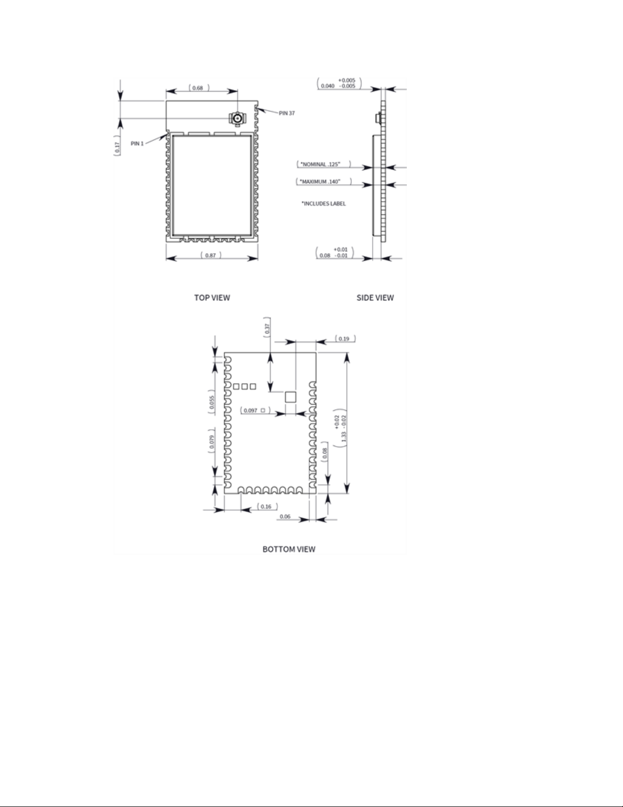
Mechanical drawings
The following images show the XTC mechanical drawings. The XTC has the same form factor as other Digi
surface mount (SMT) XBee devices, except there is an additional copper ground pad on the bottom.
XBee/XBee-PRO XTend Compatible (XTC) RF Module User Guide 14
Page 15
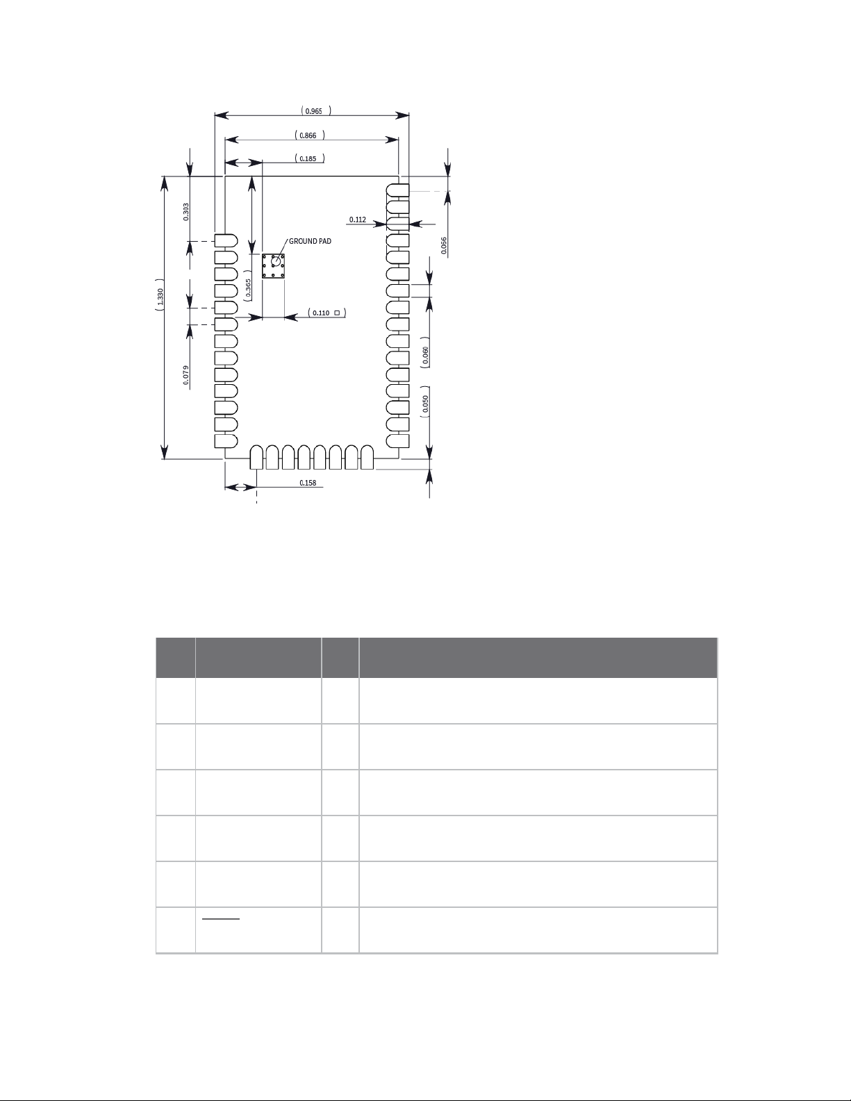
Mechanical drawings
XBee/XBee-PRO XTend Compatible (XTC) RF Module User Guide 15
Page 16
Pin signals
Pin signals
The following table describes the pin signals. Low-asserted signals have a horizontal line over the signal
name.
Pin Designation I/O Function
1 GND - Ground
2 VCC I Power supply
3 DOUT O UART Data Out
4 DIN I UART Data In
5 GPO2/RX LED O General Purpose Output / RX LED
RESET
6
I Module reset
XBee/XBee-PRO XTend Compatible (XTC) RF Module User Guide 16
Page 17

Pin Designation I/O Function
7 RSSI O RX Signal Strength Indicator
8 - Disabled
9 Reserved NC Do not connect
10 SLEEP (DTR) I Pin Sleep Control Line
11 GND - Ground
12 - Disabled
13 GND - Ground
Pin signals
14 - Disabled
15 - Disabled
16 - Disabled
17 - Disabled
18 Reserved NC Do not connect
19 Reserved NC Do not connect
20 Reserved NC Do not connect
21 Reserved NC Do not connect
22 GND - Ground
23 Reserved NC Do not connect
24 - Disabled
XBee/XBee-PRO XTend Compatible (XTC) RF Module User Guide 17
Page 18

Pin Designation I/O Function
Pin signals
25 GPO1/CTS/RS-
485 TX_EN
26 ON/SLEEP O Module sleep status indicator
27 Reserved NC Do not connect
28 TX_PWR O Transmit power
29 RTS/CMD I Request-to-Send Flow Control / Binary Command Control
30 - Disabled
31 - Disabled
CONFIG
32
33 - Disabled
O General Purpose Output / Clear-to-Send Flow Control /
RS-485 Transmit Enable
I Configuration
34 Reserved NC
35 GND - Ground
36 RF I/O RF IO for RF pad variant
37 NC NC
38 GND - Ground pad for heat transfer to host PCB
Note If you integrate the XTC with a host PC board, leave all lines you do not use disconnected
(floating).
Recommended pin connections
The only required pin connections are VCC, GND, DOUT and DIN. To support serial firmware updates, you
should connect VCC, GND, DOUT, DIN, RTS, and SLEEP (DTR).
XBee/XBee-PRO XTend Compatible (XTC) RF Module User Guide 18
Page 19

XTC RF Module Modes
Transparent and API operating modes
The firmware operates in several different modes. Two top-level modes establish how the device
communicates with other devices through its serial interface: Transparent operating mode and API
operating mode.
Transparent operating mode
Devices operate in this mode by default. We also call this mode “AT operating mode.” The device acts as a
serial line replacement when it is in Transparent operating mode. The device queues all UART data it
receives through the DIN pin for RF transmission. When a device receives RF data, it sends the data out
through the DOUT pin. You can set the configuration parameters using the AT Command interface.
API operating mode
API operating mode is an alternative to Transparent mode. API mode is a frame-based protocol that
allows you to direct data on a packet basis. It can be particularly useful in large networks where you need
to control the route a data packet takes or when you need to know which node a data packet is from. The
device communicates UART data in packets, also known as API frames. This mode allows for structured
communications with serial devices. It is helpful in managing larger networks and is more appropriate for
performing tasks such as collecting data from multiple locations or controlling multiple devices remotely.
There are two types of API operating modes: one with escaped characters and another without escaped
characters.
l Without escaped characters (AP = 1). This mode eliminates escaping character sequences.
This makes it simpler to create code and libraries, but runs a minor risk of lost frames or
errors due to the possibility that payload data can be confused with frame structure. We
do not recommend this mode for noisy radio environments and where payload data may
include special characters (specifically 0x7E, 0x7D, 0x11, and 0x13).
XBee/XBee-PRO XTend Compatible (XTC) RF Module User Guide 19
Page 20

Additional modes
l With escaped characters (AP = 2). API escaped operating mode works similarly to API
mode. The only difference is that when working in API escaped mode, the software must
escape any payload bytes that match API frame specific data, such as the start-of-frame
byte (0x7E).
Additional modes
In addition to the serial communication modes, several modes apply to how to configure devices and how
devices communicate with each other.
Command mode
Command mode is a state in which the firmware interprets incoming characters as commands. Command
mode allows you to modify the device’s firmware using parameters you can set using AT commands. When
you want to read or set any setting of the device, you have to send it an AT command. Every AT command
starts with the letters "AT" followed by the two characters that identify the command the device issues
and then by some optional configuration values. For more details, see Enter Command mode on the next
page.
Binary Command mode
Binary Command mode allows you to configure a device at a faster rate than AT commands will allow.
Using binary commands to send and receive parameter values is the fastest way to change the operating
parameters of the device. Use binary commands to:
l Sample signal strength and/or error counts;
l Change device addresses and channels for polling systems when a quick response is
necessary.
For more details, see Enter Binary Command mode on page 23 and DB (Received Signal Strength) on page
46.
Idle mode
When not receiving or transmitting data, the device is in Idle mode. During Idle mode, the device listens for
valid data on the serial port.
Receive mode
If a destination node receives a valid RF packet, the destination node transfers the data to its serial
transmit buffer. For the serial interface to report receive data on the RF network, that data must meet
the following criteria:
XBee/XBee-PRO XTend Compatible (XTC) RF Module User Guide 20
Page 21

Additional modes
l ID match
l Channel match
l Address match
Sleep modes
Sleep Modes enable the device to enter states of low-power consumption when not in use. The device
support three software sleep modes:
l Pin Sleep: the host controls this
l Serial Port Sleep: wakes when it detects serial port activity
l Cyclic Sleep: wakes when it detects RF activity
For more information, see Sleep modes on page 25.
Shutdown mode
Shutdown mode offers the lowest power mode available to the device. This is helpful for applications that
must keep power consumption to a minimum during idle periods.
When you drive the SHDN pin (pin 7) low, it forces the device into Shutdown mode. This halts any
communication in progress (transmit or receive) and any buffered data is lost. For any other mode of
operation, you must drive or pull SHDN high.
Immediately after the SHDN pin changes states from low to high, the device resets. After reset, the
application must observe a delay time of <100 ms.
While SHDN is driven low, the device sets the following pins to high impedance: DCD, TX_PWR, RX LED, DO
and CTS. The SHDN line is driven low during shutdown.
The following input pins may continue to be driven by external circuitry when in shutdown mode: RTS, DI
and SHDN.
Because the DO pin is set to high impedance during Shutdown, if the XTC RF Module is connected to a
processor, the UART receive pin could be floating. Place a weak pull-up between the device and the
microcontroller so that the application does not misinterpret noise as data.
Transmit mode
When the device receives serial data and is ready to packetize it, the device exits Idle mode and attempts
to transmit the serial data.
Enter Command mode
There are two ways to enter Command mode:
XBee/XBee-PRO XTend Compatible (XTC) RF Module User Guide 21
Page 22

Additional modes
1. To get a device to switch into this mode, you must issue a unique string of text in a special
way: +++ (default). When the device sees a full second of silence in the data stream
followed by the string +++ (without Enter or Return) and another full second of silence, it
knows to stop sending data through and start accepting commands locally.
Do not press Return or Enter after typing +++ because it will interrupt the guard time
silence and prevent you from entering Command mode.
2. Assert (low) the CONFIG pin. Turn the power going to the device off and back on.
The device sends the letters OK followed by a carriage return out of the UART to indicate that it entered
Command mode.
You can customize the guard times and timeout in the device’s configuration settings. See CC (Command
Sequence Character) on page 42, BT (Guard Time Before) on page 41 and AT (Guard Time After) on page
41.
Send AT commands
Once the device enters Command mode, use the syntax in the following figure to send AT commands.
To read a parameter value stored in the device’s register, omit the parameter field.
The preceding example would enable software flow control.
To store the new value to non-volatile (long term) memory, send the WR (Write) command. This allows
parameter values that you modify to persist in the device's registry after a reset. Otherwise, the device
restores parameters to the previous values after a reset.
Respond to AT commands
When you send a command to the device, the device parses and runs the command. If the command runs
successfully, the device returns an OK message. If the command errors, the device returns an ERROR
message.
Exit Command mode
1. Send the CN (Exit Command Mode) command followed by a carriage return.
or:
2. If the device does not receive any valid AT commands within the time specified by CT
(Command Mode Timeout), it returns to Idle mode. The default Command Mode Timeout is
20 seconds.
XBee/XBee-PRO XTend Compatible (XTC) RF Module User Guide 22
Page 23

Additional modes
Enter Binary Command mode
To enter Binary Command mode, you must first be in Command mode:
1. Set RT to 1; see RT (GPI1 Configuration) on page 82.
2. Assert CMD by driving pin 1029 high to enter Binary Command mode.
3. Disable hardware flow control.
CTS (pin 25) is high when the firmware executes a command. That is why you must disable hardware flow
control, because CTS holds off parameter bytes.
Exit Binary Command mode
To exit Binary Command mode, de-assert CMD by driving pin 2910 low.
Binary Command mode FAQs
Since sending and receiving binary commands takes place through the same serial data path as live data,
interference between the two types of data can be a concern. Some common questions about using binary
commands are:
l What are the implications of asserting CMD while the device is sending or receiving live
data?
You must assert the CMD pin (pin 2910) in order to send binary commands to the device. You can assert
the CMD pin to recognize binary commands anytime during the transmission or reception of data.
The device only checks the status of the CMD signal at the end of the stop bit as the byte shifts into the
serial port.
The firmware does not allow control over when the device receives data, except by waiting for dead
time between bursts of communication.
If the command is sent in the middle of a stream of payload data, the device executes the command in
the order it is received. If the device is continuously receiving data, it waits for a break in the data it
receives before executing the command.
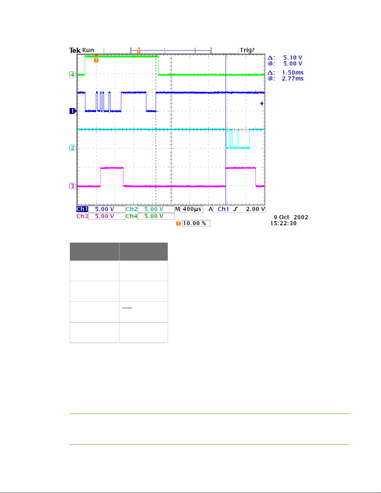
In the following figure, the host writes a value to a register and then reads it out of the device to verify
it. While not in the middle of other received data, the CTS signal outlines the data response out of the
device.
XBee/XBee-PRO XTend Compatible (XTC) RF Module User Guide 23
Page 24
Additional modes
Signal number Pin name
1 DIN (Pin 4)
2 DOUT (Pin 3)
3 CTS (Pin 259)
4 CMD (Pin 2910)
l After sending serial data, is there a minimum time delay before you can assert CMD?
l Is a time delay required after CMD is de-asserted before payload data can be sent?
The host must observe a minimum time delay of 100 µs after sending the stop bit of the command byte
before the host de-asserts the CMD pin. The command executes after the host sends all of its
associated parameters. If the device does not receive all of these parameters within 0.5 seconds, the
device returns to Idle mode.
Note When a host sends parameters, they are two bytes long with the least significant byte sent first.
Binary commands that return one parameter byte must be written with two parameter bytes.
Example: to set PL to 3, send the following data: 0x3A 0x03 0x00 (Binary Command, LSB, MSB).
XBee/XBee-PRO XTend Compatible (XTC) RF Module User Guide 24
Page 25

Sleep modes
l How does one discern between live data and data received in response to a command?
To query command parameters using Binary Command mode, set the most significant bit of the binary
command. This can be accomplished by logically ORing (bit-wise) the binary command with
hexadecimal 0x80. The parameter bytes are returned in hexadecimal bytes with the least significant
bit first (if multiple bytes are returned).
Example: to query HP in Binary Command mode, instead of setting it, send 0x11 (HP binary command)
as 0x91 with no parameter bytes.
The device must be in Binary Command mode in order for the device to recognize a binary command;
see Enter Binary Command mode on page 23.
If the device is not in Binary Command mode (the RT parameter value is not 1), the device does not
recognize that the CMD pin is asserted and therefore does not recognize the data as binary
commands.
For an example of binary programming, see Send binary commands on page 35.
Sleep modes
For the device to enter one of the sleep modes, SM must have a non-zero parameter value, and it must
meet one of the following conditions:
1. The device is idle (no data transmission or reception) for the amount of time defined by
the ST parameter. ST is only active when SM = 4-5.
2. The host asserts SLEEP (pin 10). This only applies to the Pin Sleep option.
When in Sleep mode, the device does not transmit or receive data until it transitions to Idle mode.
Use the SM command to enable or disable all Sleep modes. The following table shows the transitions into
and out of Sleep modes.
Sleep
mode
(setting)
Pin Sleep
(SM = 1)
Transition into
Sleep mode
Assert (high) SLEEP pin. A
microcontroller can shut
down and wake devices via
the SLEEP pin.
The device completes a
transmission or reception
before activating Pin Sleep.
Transition out of Sleep
mode (wake)
Related
commands
De-assert (low) SLEEP pin SM
Power
consumption
< 147 µA
XBee/XBee-PRO XTend Compatible (XTC) RF Module User Guide 25
Page 26

Sleep modes
Sleep
mode
(setting)
Serial
Port
Sleep
(SM = 2)
Cyclic
Sleep
(SM = 4 -
8)
Transition into
Sleep mode
Automatic transition to Sleep
Mode occurs after a user-
Transition out of Sleep
mode (wake)
When a serial byte is
received on the DI pin
defined period of inactivity
(no transmitting or receiving
of data).
Period of inactivity is defined
by the ST command.
The device transitions in and out of Sleep Mode in cycles
(you set the sleep interval of time using the SM command).
The cyclic sleep interval of time must be shorter than the
interval of time that is defined by the LH command.
You can for the device into Idle Mode using the SLEEP pin if
you issue the PW command.
Related
commands
Power
consumption
(SM), ST 7.3 mA
(SM), ST,
HT, LH, PW
See Power
requirements
The SM (Sleep Mode) command is central to setting all Sleep Mode configurations. By default, Sleep Modes
are disabled (SM = 0) and the device remains in Idle/Receive Mode. When in this state, the device remains
constantly ready to respond to serial or RF activity.
Pin Sleep (SM = 1)
l Pin/Host-controlled
l Typical sleep current: 2.5 µA
When the host asserts the SLEEP pin, the device finishes any transmitting or receiving activity, enters Idle
mode, then enters a sleep state. When in Pin Sleep mode, the device does not respond to serial or RF
activity.
After enabling Pin Sleep, the SLEEP pin controls whether the device is active or sleeping. When the host de-
asserts SLEEP, the device is fully operational. When the host asserts SLEEP, the device transitions to Sleep
mode and remains in its lowest power-consuming state until the host de-asserts the pin. This pin is only
active if the device is setup to operate in this mode; otherwise the firmware ignores the pin.
Once in Pin Sleep, the device de-asserts (high) CTS (pin 259) , indicating that other devices should not send
data to the device. The device also de-asserts (low) the TX_PWR line (pin 284) when the device is in Pin
Sleep mode.
Note The device completes a transmission or reception before activating Pin Sleep.
XBee/XBee-PRO XTend Compatible (XTC) RF Module User Guide 26
Page 27

Sleep modes
Serial Port Sleep (SM = 2)
l Wake on serial port activity
l Typical sleep current: 6.3 mA
Serial Port Sleep is a Sleep mode in which the device runs in a low power state until it detects serial data
on the DI pin.
The ST command determines the period of time that the device sleeps. Once it receives a character
through the DI pin, the device returns to Idle mode and is fully operational.
Cyclic Sleep Mode (SM = 4-8)
l Typical sleep Current: 2.5 µA (when asleep)
Cyclic Sleep modes allow device wakes according to the times designated by the cyclic sleep settings. If
the device detects a wake-up initializer during the time it is awake, the device synchronizes with the
transmitting device and receives data after the wake-up initializer runs its duration. Otherwise, the device
returns to Sleep mode and continues to cycle in and out of activity until a wake-up initializer is detected.
While the device is in Cyclic Sleep mode, it de-asserts (high) CTS (pin 259) to indicate not to send data to
the device. When the device awakens to listen for data, it asserts CTS and transmits any data received on
the DI pin. The device also de-asserts (low) the TX_PWR (pin 284) when it is in Cyclic Sleep mode.
The device remains in Sleep mode for a user-defined period of time ranging from 1 second to 16 seconds
(SM parameters 4 through 8). After this interval of time, the device returns to Idle mode and listens for a
valid data packet. The listen time depends on the BR parameter setting. The default BR setting of 1
requires at least a 35 ms wake time, while the BR setting of 0 requires a wake time of up to 225 ms. If the
device does not detect valid data on any frequency, it returns to Sleep mode. If it detects valid data, it
transitions into Receive mode and receives the incoming RF packets. The device then returns to Sleep
mode after a period of inactivity determined by the ST parameter.
You can also configure the device to wake from cyclic sleep when the SLEEP pin is de-asserted. To
configure a device to operate in this manner, you must issue the PW (Pin Wake-up) command. When you
de-assert the SLEEP pin, it forces the device into Idle mode and it can begin transmitting or receiving data.
It remains active until it no longer detects data for the time that ST specifies, at which point it resumes its
low-power cyclic state.
Cyclic scanning
Each RF transmission consists of an RF initializer and payload. The RF initializer contains initialization
information and all receiving devices must wake during the wake-up initializer portion of data
transmission in order to synchronize with the transmitting device and receive the data.
The cyclic interval time defined by the SM (Sleep Mode) command must be shorter than the interval time
defined by LH (Wake-up Initializer Timer) command.
XBee/XBee-PRO XTend Compatible (XTC) RF Module User Guide 27
Page 28
Sleep modes
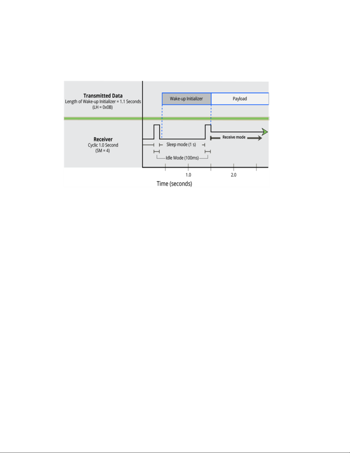
Correct configuration (LH > SM)
In the following figure, the length of the wake-up initializer exceeds the time interval of Cyclic Sleep. The
receiver is guaranteed to detect the wake-up initializer and receive the accompanying payload data.
XBee/XBee-PRO XTend Compatible (XTC) RF Module User Guide 28
Page 29
Operation
When operating at 1 W power output, observe a minimum separation distance of 6 ft (2 m)
between devices. Transmitting in close proximity of other devices can damage the device's
front end.
Serial interface
The XTC RF Module provides a serial interface to an RF link. The XTC RF Module converts serial data to RF
data and sends that data to any over-the-air compatible device in an RF network. The device can
communicate through its serial port with any logic and voltage compatible universal asynchronous
receiver/transmitter (UART), or through a level translator to any serial device.
UART data flow
Devices that have a UART interface can connect directly to the pins of the XTC RF Module as the following
figure shows. The figure shows system data flow in a UART-interfaced environment. Low-asserted signals
have a horizontal line over the signal name.
Serial data
A device sends data to the device's UART through pin 4 (DIN) as an asynchronous serial signal. When the
device is not transmitting data, the signal idles high.
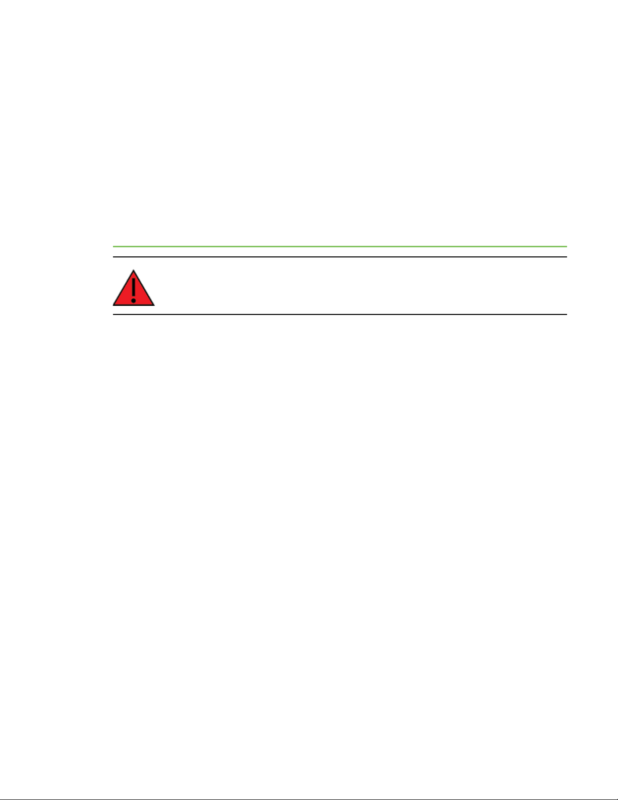
For serial communication to occur, you must configure the UART of both devices with compatible settings
for the baud rate, parity, start bits, stop bits, and data bits. Each data byte consists of a start bit (low), 8
data bits (least significant bit first) and a stop bit (high). The following diagram illustrates the serial bit
pattern of data passing through the device. It shows UART data packet 0x1F (decimal number 31) as
transmitted through the device.
XBee/XBee-PRO XTend Compatible (XTC) RF Module User Guide 29
Page 30
Flow control
Flow control
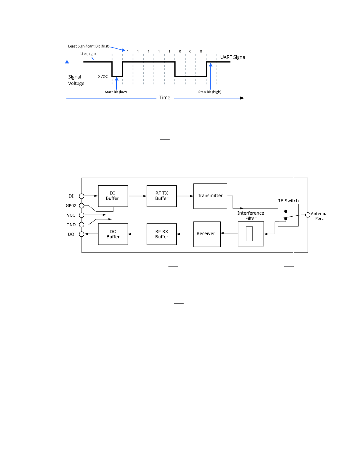
The RTS and CTS device pins provide RTS and/or CTS flow control. CTS flow control signals the host to
stop sending serial data to the device. RTS flow control lets the host signal the device so it will not send
the data in the serial transmit buffer out the UART. The following diagram shows the internal data flow,
with the five most common pin signals.
The firmware has Hardware flow control (CTS) configured by default. You must configure CTSflow control
on the host side for it to work.
You must configure Software flow control (XON) on both the host and device side for it to work.
If you change the CS command from 0, then CTSflow control will not work even if you have it configured
on the host.
Data In (DIN) buffer and flow control
When serial data enters the device through the DIN pin (pin 4), it stores the data in the DIN buffer until it
can process the data.
When the firmware satisfies the RB and RO parameter thresholds, the device attempts to initialize an RF
transmission. If the device is already receiving RF data, it stores the serial data in the device's DIN buffer.
The device creates and transmits data packets when it meets one of the following conditions:
XBee/XBee-PRO XTend Compatible (XTC) RF Module User Guide 30
Page 31

Flow control
1. The device does not receive any serial characters for the amount of time set with in the
RO command; see RO (Packetization Timeout) on page 81.
2. The device receives the maximum number of characters that fits in an RF packet.
3. The device receives the Command Mode sequence; see Enter Command mode on page 21.
If the DIN buffer becomes full, you must implement hardware or software flow control in order to prevent
overflow (loss of data between the host and the device). To eliminate the need for flow control:
1. Send messages that are smaller than the DIN buffer size. The size of the DIN buffer varies
according to the packet size (PK parameter) and the parity setting (NB parameter) you
use.
2. Interface at a lower baud rate (BD parameter) than the RF data rate (BR parameter).
In the following situations, the DIN buffer may become full and overflow:
1. If you set the serial interface data rate higher than the RF data rate of the device, the
device receives data from the host faster than it can transmit the data over-the-air.
2. If the device receives a continuous stream of RF data or if the device monitors data on a
network, it places any serial data that arrives on the DIN pin (pin 4) in the DIN buffer. It
transmits the data in the DIN buffer over-the-air when the device no longer detects RF
data in the network.
Hardware flow control (CTS)
The firmware asserts CTS before the DIN buffer is full so it has time to send the signal and the host has
time to stop sending data.
When the DIN buffer is full, the firmware de-asserts CTS (high) to signal the host to stop sending data;
refer to FT (Flow Control Threshold) on page 79 and CS (GP01 Configuration) on page 77.
The firmware re-asserts CTS after the DIN buffer has 34 bytes of memory available.
Software flow control (XON/OFF)
Use FL to enable XON/XOFF software flow control. This option only works with ASCII data.
Data Out (DO) buffer and flow control
When a device receives RF data, the data enters the DOUT buffer and the device sends it out the serial
port to a host device. Once the DOUT buffer reaches capacity, it loses any additional incoming RF data. The
DOUT buffer stores at least 2.1 kB.
In the following situations, the DOUT buffer may become full and overflow:
1. If you set the interface data rate higher than the RF data rate of the device, the receiving
device receives data from the transmitting device faster than it can send the data to the
XBee/XBee-PRO XTend Compatible (XTC) RF Module User Guide 31
Page 32

host.
2. If the host does not allow the device to transmit data out from the DOUT buffer because
of being held off by hardware or software flow control.
Flow control
XBee/XBee-PRO XTend Compatible (XTC) RF Module User Guide 32
Page 33

Configure the XTC RF Module
Configure the device using XCTU
XBee Configuration and Test Utility (XCTU) is a multi-platform program that enables developers to
interact with Digi radio frequency (RF) devices through a graphical interface. The application includes built-
in tools that make it easy to set up, configure, and test Digi RF devices.
For full support of the XTC RF Module, you must use XCTU version 6.3.0 or higher.
For instructions on downloading and using XCTU, go to:
http://www.digi.com/products/xbee-rf-solutions/xctu-software/xctu
XBee/XBee-PRO XTend Compatible (XTC) RF Module User Guide 33
Page 34

Program the XTC RF Module
XTC RF Module programming examples
For steps on sending AT commands to a device, refer to:
l Send AT commands on page 22
l Exit Command mode on page 22
Refer to the online help for XCTU for more information on the program and how to use it. The help
information is available at:
https://docs.digi.com/display/XCTU/XCTU+Overview
Connect the device to a PC
The programming examples that follow require the installation of XCTU and a serial connection to a PC.
Digi stocks connector boards to facilitate interfacing with a PC.
1. Download XCTU from Digi’s website:
http://www.digi.com/products/xbee-rf-solutions/xctu-software/xctu#resources
2. After the .exe file downloads to the PC, double-click the file to launch the XCTU Setup
Wizard. Follow the steps in the wizard to completely install XCTU.
3. Mount the device to an interface board, then connect the assembly to a PC.
4. Launch XCTU and click the Add devices tab on the upper left corner of the screen.
5. Verify that the baud rate and parity settings of the Serial/USB port match those of the
device.
Note Failure to enter Command mode is commonly due to baud rate mismatch. Ensure
that the Baud Rate: setting on the Add radio device window matches the
interface data rate of the device. By default, the BD parameter = 9600 b/s.
XBee/XBee-PRO XTend Compatible (XTC) RF Module User Guide 34
Page 35

XTC RF Module programming examples
Modify a device address
The following programming example shows you how to modify the device's destination address.
1. Once you add the device in XCTU, click on it in the Radio Modules pane to display the
Configuration working mode. This mode shows most of the device’s parameters that you
can edit.
2. Scroll down in the Radio Configuration pane until you find the parameter you want to edit,
in this case the DT (Destination Address) parameter, or use the search box and type DT.
XCTU automatically scrolls to the selected parameter.
3. When you locate the parameter, change its value, for example to 1A0D. If you do not save
the parameter, the color of the surrounding container is light green.
4. Click the write button to save the value to non-volatile memory; it is the pencil icon to the
right of the parameter . If you change other parameters but have not saved them, you
can use the Write radio settings button to save them. It is the white and blue pencil icon
on the top of the configuration panel .
Restore device defaults
The following programming example shows you how to restore a device's default parameters.
1. After establishing a connection between the device and a PC click the Configuration
working mode tab of XCTU .
2. Click the Load default firmware settings button and agree to restore the default values.
The button is the factory icon .
3. The restored parameters have a light green surrounding color, which means that they
have been changed but not saved.
Click the Write module settings button to save all of the parameters simultaneously.
4.
5. All the parameters surrounding box must change to gray indicating that their values are
now saved in the device's non-volatile memory.
Send binary commands
Example: use XCTU's Serial Console tool to change the device's DT (Destination Address) parameter and
save the new address to non-volatile memory.
This example requires XCTU and a serial connection to a PC.
To send binary commands:
1. Set the RT command to 1 to enable binary command programming; do this in Command
mode or configure it through XCTU.
XBee/XBee-PRO XTend Compatible (XTC) RF Module User Guide 35
Page 36

XTC RF Module programming examples
2. Drive pin 2910 high to assert CMD. To accomplish this, de-assert the RTS line in XCTU. The
device enters Binary Command mode.
3. Send hexadecimal bytes (parameter bytes must be 2 bytes long). The next four lines are
examples, not required values:
00 (Send binary command DT)
0D (Least significant byte of parameter bytes)
1A (Most significant byte of parameter bytes)
08 (Send binary command WR)
4. Drive pin 2910 low to de-assert CMD. After you send the commands, CTS (pin 259) will de-
assert (driven low) temporarily. The device exits Binary Command mode.
The default flow control is NONE, so if you are using XCTU, you should not need to worry about CTS.
However, you can still observe the behavior of the CTS line by monitoring the CTS indicator in the terminal
or console.
Query binary commands
Example: use XCTU's Serial Console tool to query the device's DT (Destination Address) and DB (Received
Signal strength) parameters. In order to query a parameter instead of setting it, you must logically OR the
binary command byte with 0x80.
1. Set the RT command to 1 to enable binary command programming. To do this, you must
either be in Command mode or use XCTU to configure the device.
2. Assert CMD by driving pin 29 high. To do this de-assert the RTS line in XCTU.
3. Send hexadecimal bytes:
80 (Binary command DT (0x00) ORed with 0x80)
B6 (Binary command DB (0x36) ORed with 0x80)
4. Read the device's output for the parameter values of the two commands.
5. De-assert CMD by driving pin 29 low. The device exits Binary Command mode.
When querying commands in binary command mode, the output is the least significant byte followed by
the most significant byte and is always represented in hexadecimal values.
XBee/XBee-PRO XTend Compatible (XTC) RF Module User Guide 36
Page 37

XTC RF Module commands
The following table lists the AT and binary commands in the XTC RF Module firmware and links to the
description of the individual command.
By default, the device expects numerical values in hexadecimal since the default value of the CF (Number
Base) Parameter is 1. Hexadecimal values are designated by the 0x prefix and decimal values by the d
suffix.
AT command Binary command
%V (Board Voltage) on page 45
AM (Auto-set MY) on page 58
AP (API Enable) on page 74
AT (Guard Time After) on page 41
BD (Interface Data Rate) on page 74
BR (RF Data Rate) on page 65
BT (Guard Time Before) on page 41
CC (Command Sequence Character) on page 42
CD (GP02 Configuration) on page 76
0x3B (59d)
0x41 (65d)
--
0x05 (5d)
0x15 (21d)
0x39 (57d)
0x04 (4d)
0x13 (19d)
0x28 (40d)
XBee/XBee-PRO XTend Compatible (XTC) RF Module User Guide 37
Page 38

AT command Binary command
CF (Number Base) on page 42
CN (Exit Command Mode) on page 43
CS (GP01 Configuration) on page 77
CT (Command Mode Timeout) on page 44
DB (Received Signal Strength) on page 46
DT (Destination Address) on page 59
E0 (Echo Off) on page 44
E1 (Echo On) on page 45
ER (Receive Count Error)
--
0x09 (9d)
0x1F (31d)
0x06 (6d)
0x36 (54d)
0x00 (0d)
0x0A (10d)
0x0B (11d)
0x0F (15d)
FH (Force Wakeup Initializer) on page 83
FL (Software Flow Control) on page 78
FS (Forced Synch Time) on page 66
FT (Flow Control Threshold) on page 79
GD (Receive Good Count) on page 47
HP (Preamble ID) on page 60
HT (Time before Wake-up Initializer) on page 84
HV (Hardware Version) on page 48
ID (Network ID) on page 60
0x0D (13d)
0x07 (7d)
0x3F (63d)
0x24 (36d)
0x10 (16d)
0x11 (17d)
0x03 (3d)
--
0x27 (39d)
XBee/XBee-PRO XTend Compatible (XTC) RF Module User Guide 38
Page 39

AT command Binary command
KY (AES Encryption Key) on page 73
LH (Wakeup Initializer Timer) on page 84
MD (RF Mode) on page 66
MK (Address Mask) on page 61
MT (Multi-transmit) on page 61
MY (Source Address) on page 62
NB (Parity) on page 79
PB (Polling Begin Address) on page 67
PD (Minimum Polling Delay) on page 68
0x43 (67d)
0x0C (12d)
0x31 (49d)
0x12 (18d)
0x3E (62d)
0x2A (42d)
0x23 (35d)
0x45 (69d)
0x47 (71d)
PE (Polling End Address) on page 68
PK (Maximum RF Packet Size) on page 69
PL (TX Power Level) on page 71
PW (Pin Wakeup) on page 85
RB (Packetization Threshold) on page 80
RC (Ambient Power - Single Channel) on page 48
RE (Restore Defaults) on page 49
RM (Ambient Power) on page 50
RN (Delay Slots) on page 63
0x46 (70d)
0x29 (41d)
0x3A (58d)
0x1D (29d)
0x20 (32d)
--
0x0E (14d)
--
0x19 (25d)
XBee/XBee-PRO XTend Compatible (XTC) RF Module User Guide 39
Page 40

AT command Binary command
RO (Packetization Timeout) on page 81
RP (RSSI PWM Timer) on page 51
0x21 (33d)
0x22 (34d)
RR (Retries) on page 64 0x18 (24d)
RT (GPI1 Configuration) on page 82
SB (Stop Bits) on page 82
SH (Serial Number High) on page 52
SL (Serial Number Low) on page 52
SM (Sleep Mode) on page 86
ST (Time before Sleep) on page 87
0x16 (22d)
0x37 (55d)
0x25 (37d)
0x26 (38d)
0x01 (1d)
0x02 (2d)
TP (Board Temperature) on page 53
TR (Transmit Error Count) on page 53
TT (Streaming Limit) on page 64
TX (Transmit Only) on page 72
VL (Firmware Version - Verbose) on page 54
VR (Firmware Version - Short) on page 54
WA (Active Warning Numbers) on page 55
WN (Warning Data) on page 56
WR (Write) on page 88
0x38 (56d)
0x1B (27d)
0x1A (26d)
0x40 (64d)
--
0x14 (20d)
--
--
0x08 (8d)
XBee/XBee-PRO XTend Compatible (XTC) RF Module User Guide 40
Page 41

AT command Binary command
Command mode options
WS (Sticky Warning Numbers) on page 58
--
Command mode options
The following AT commands are Command mode option commands.
AT (Guard Time After)
Sets or reads the time-of-silence that follows the CC (Command Sequence Character) of the Command
mode sequence (BT + CC + AT). By default, one second must elapse before and after the command
sequence character.
The times-of-silence surrounding the Command Sequence Character prevent the device from
inadvertently entering Command mode.
Binary command
0x05 (5 decimal)
Command type
Command mode options
Parameter range
2 - (ST-3) up to 0x1770 [x 100 ms]
Default
0xA (1 second)
Bytes returned
2
BT (Guard Time Before)
Sets the DI pin silence time that must precede the Command Sequence Character (CC command) of the
Command mode sequence. For more information about the Command mode sequence, see Enter
Command mode on page 21.
Binary command
0x04 (4 decimal)
XBee/XBee-PRO XTend Compatible (XTC) RF Module User Guide 41
Page 42

Command mode options
Command type
Command mode options
Parameter range
0 - 0x1770 [x 100ms]
Default
0x0A (1 second)
Bytes returned
2
CC (Command Sequence Character)
The ASCII character value you use to enter Command mode. Use CC to set or read the character used
between guard times of the Command mode sequence (BT + CC + AT). This sequence enters the device
into Command mode so that device recognizes data entering it from the host as commands instead of
payload data.
Binary command
0x13 (19 decimal)
Command type
Command mode options
Parameter range
0x20 - 0x7F
Default
0x2B (ASCII “+”)
Bytes returned
1
CF (Number Base)
Sets or reads the command formatting setting.
The firmware always enters and reads the following commands in hex, no matter what the CF setting is:
XBee/XBee-PRO XTend Compatible (XTC) RF Module User Guide 42
Page 43

VR (Firmware Version)
HV (Hardware Version)
KY (AES Encryption Key)
Binary command
N/A
Command type
Command mode options
Parameter range
0 - 2
Parameter Configuration
Command mode options
0 Commands use the default number base; decimal commands may output units.
1 All commands are forced to unsigned, unit-less hex.
2 Commands use their default number base; no units are output.
Default
1
Bytes returned
1
CN (Exit Command Mode)
Makes the device exit Command mode.
Binary command
0x09 (9 decimal)
Command type
Command mode options
XBee/XBee-PRO XTend Compatible (XTC) RF Module User Guide 43
Page 44

Command mode options
Parameter range
N/A
Default
N/A
Bytes returned
N/A
CT (Command Mode Timeout)
Set or read the Command mode timeout parameter. If a device does not receive any valid commands
within this time period, it returns to Idle mode from Command mode.
Use the CN (Exit Command mode) command to exit Command mode manually.
Binary command
0x06 (6 decimal)
Command type
Command mode options
Parameter range
2 - 0x53E2 [x 100 milliseconds]
Default
0xC8 (20 seconds)
Bytes returned
2
E0 (Echo Off)
Turns off the character echo in Command mode.
By default, echo is off.
Binary command
0x0A (10 decimal)
XBee/XBee-PRO XTend Compatible (XTC) RF Module User Guide 44
Page 45

Diagnostic commands
Command type
Command mode options
Parameter range
N/A
Default
N/A
Bytes returned
N/A
E1 (Echo On)
Enables character echo in Command mode. Each character that you type echoes back to the terminal
when E1 is active. E0 (Echo Off) is the default.
Binary command
0x0B (11 decimal)
Command type
Command mode options
Parameter range
N/A
Default
N/A
Bytes returned
N/A
Diagnostic commands
The following AT commands are diagnostic commands. Diagnostic commands are typically volatile and will
not persist across a power cycle.
%V (Board Voltage)
Reads the supply voltage to the module's VCC (pin 2).
XBee/XBee-PRO XTend Compatible (XTC) RF Module User Guide 45
Page 46

The conversion of the hex value returned by %V to Volts is VAL/65536 = Volts.
Example:
2.8 VDC = 2.8 * 65536 = 0x2CCCD
3.3 VDC = 3.3 * 65536 = 0x34CCD
Sample output
3.27 V (when CF = 0)
Diagnostic commands
345E3 (when CF = 1)
3.27 (when CF = 2)
Binary command
0x3B (59 decimal)
Parameter range
(read-only):
0x26666 - 0x39999 (2.40 to 3.60 V)
Default
N/A
Bytes returned
4
1
DB (Received Signal Strength)
This command reports the received signal strength indicator (RSSI) of the last RF data packet that a
device receives. It reports the RSSI in decibels relative to milliwatts. DB is useful in determining range
characteristics of the RF devices under various conditions. On XTC, this is accurate from approximately -50
to -100 dBm.
In Transparent operating mode, DB shows the power level in signed decimal format with the units (dBm).
If CF = 1, the magnitude of the value is in unsigned hex. If CF = 2, the value is in decimal, but without the
units.
1
When CF = 1 (default), the firmware shows a hex integer that is equal to (voltage * 65536d).
XBee/XBee-PRO XTend Compatible (XTC) RF Module User Guide 46
Page 47

Diagnostic commands
Sample output
-88 dBm (when CF = 0)
58 (when CF = 1)
-88 (when CF = 2)
Note If the firmware reads the DB register before the device receives an RF packet, the devices returns
a value of 0x8000.
Binary command
0x36 (54 decimal)
Command type
Diagnostics
Parameter range
(read-only): 0x6E - 0x28
(-110 to -40 decimal)
Default
N/A
Bytes returned
2
GD (Receive Good Count)
Sets or reads the number of RF packets with valid MAC headers that the device receives successfully on
the RF interface. When the value reaches 0xFFFF, it stays there until you manually change the maximum
count value or reset the device.
Its parameter value is reset to 0 after every device reset and is not non-volatile; the parameter value does
not persist in the device's memory after a power-up sequence.
Pin, serial port or cyclic sleep modes do not reset the GD parameter.
Binary command
0x10 (16 decimal)
XBee/XBee-PRO XTend Compatible (XTC) RF Module User Guide 47
Page 48

Command type
Diagnostics
Parameter range
0 - 0xFFFF
Default
0
Bytes returned
2
HV (Hardware Version)
Reads the device's hardware version number.
Diagnostic commands
Binary command
N/A
Command type
Diagnostics
Parameter range
(read-only): 0 - 0xFFFF
Default
N/A
Bytes returned
N/A
RC (Ambient Power - Single Channel)
Reads and reports the power level on a given channel.
Sample output
-78 dBm (when CF = 0)
4e (when CF = 1)
XBee/XBee-PRO XTend Compatible (XTC) RF Module User Guide 48
Page 49

-78 (when CF = 2)
Binary command
N/A
Parameter range
(read-only): 0 - 0x31 [dBm]
Default
N/A
Bytes returned
1
RE (Restore Defaults)
Diagnostic commands
Restore device parameters to factory defaults.
RE does not cause the device to store default values to non-volatile (persistent) memory. You must send
the WR command prior to power-down or reset to save the default settings in the device's non-volatile
memory.
Binary command
0x0E (14 decimal)
Command type
Diagnostics
Parameter range
N/A
Default
N/A
Bytes returned
N/A
XBee/XBee-PRO XTend Compatible (XTC) RF Module User Guide 49
Page 50

Diagnostic commands
RM (Ambient Power)
Reads and reports power levels on all channels. If you do not provide a parameter, the device scans the
channels one time. If you do provide a parameter, the device scans the channels repeatedly for the
number of seconds that the parameter calls for. The firmware reports the maximum power level seen for
each channel (in other words, peak hold).
To implement a graphical spectrum analyzer, repeatedly send RM with no arguments and read the
resulting 50 power levels. This is easiest to do when CF = 1 or 2.
Sample output when CF = 0: Ch 0: -100 dBm
Ch 1: -103 dBm
...
Ch 49: -99 dBm
Sample output when CF = 1: 64 64
67
...
63
Sample output when CF = 2: 100 100
-103
...
-99
Binary command
N/A
XBee/XBee-PRO XTend Compatible (XTC) RF Module User Guide 50
Page 51

Diagnostic commands
Command type
Diagnostics
Parameter range
no parameter - 0x7D0
Default
N/A
Bytes returned
2
RP (RSSI PWM Timer)
Enables a pulse-width modulated (PWM) output on the RSSI pin (pin 7 of the device). We calibrate the pin
to show the difference between received signal strength and the sensitivity level of the device. PWM
pulses vary from zero to 95 percent. Zero percent means the RF signal the device receives is at or below
the device's sensitivity level.
The following table shows dB levels above sensitivity and PWM values. The total time period of the PWM
output is 8.32 ms PWM output consists of 40 steps and therefore the minimum step size is 0.208 ms.
dB above sensitivity PWM percentage (high period / total period)
10 30%
20 45%
30 60%
A non-zero value defines the time that PWM output is active with the RSSI value of the last RF packet the
device receives. After the set time when the device has not received RF packets, it sets the PWM output
low (0 percent PWM) until the device receives another RF packet. It also sets PWM output low at power-
up. A parameter value of 0xFF permanently enables PWM output and always reflects the value of the last
received RF packet.
Binary command
0x22 (34 decimal)
XBee/XBee-PRO XTend Compatible (XTC) RF Module User Guide 51
Page 52

Parameter range
0 - 0xFF [x 100 milliseconds]
Default
0x20 (3.2 seconds)
Bytes returned
1
SH (Serial Number High)
Sets or reads the device's serial number high word.
Binary command
0x25 (37 decimal)
Diagnostic commands
Command type
Diagnostics
Parameter range
0 - 0xFFFF
Default
Varies
Bytes returned
2
SL (Serial Number Low)
Sets or reads the serial number low word of the device.
Binary command
0x26 (38 decimal)
Command type
Diagnostics
XBee/XBee-PRO XTend Compatible (XTC) RF Module User Guide 52
Page 53

Diagnostic commands
Parameter range
(read-only): 0 - 0xFFFF
Default
Varies
Bytes returned
2
TP (Board Temperature)
The current module temperature in degrees Celsius in 8-bit two’s compliment format. For example 0x1A =
26°C, and 0xF6 = -10°C.
Sample output
26 C when CF = 0
1A when CF = 1
26 when CF = 2
Binary command
0x38 (56 decimal)
Parameter range
(read-only) 0 - 0x7F
Default
N/A
Bytes returned
1
TR (Transmit Error Count)
Reads the number of RF packets where retries expire without receiving an ACK (when RR > 0).
This count increments whenever a MAC transmission attempt exhausts all MAC retries without ever
receiving a MAC acknowledgment message from the destination node. Once the number reaches 0xFFFF,
it does not count further events. To reset the counter to any 16-bit value, append a hexadecimal
parameter to the command.
XBee/XBee-PRO XTend Compatible (XTC) RF Module User Guide 53
Page 54

Diagnostic commands
This value is volatile (the value does not persist in the device's memory after a power-up
sequence).
Binary command
0x1B (27 decimal)
Parameter range
0 - 0xFFFF
Default
0
Bytes returned
2
VL (Firmware Version - Verbose)
Reads the verbose firmware version of the device.
Binary command
N/A
Parameter range
Returns a string
Default
0
Bytes returned
2
VR (Firmware Version - Short)
Reads the firmware version on a device.
Firmware versions contain four significant digits: A.B.C.D. If B = 2, the device is programmed for operation
in Australia only.
Binary command
0x14 (20 decimal)
XBee/XBee-PRO XTend Compatible (XTC) RF Module User Guide 54
Page 55

Diagnostic commands
Command type
Diagnostics
Parameter range
(read-only): 0 - 0xFFFF
Default
N/A
Bytes returned
2
WA (Active Warning Numbers)
Reports the warning numbers of all active warnings, one warning number per line. It does not show
further information and does not reset warning counts. For information on what the warning numbers
mean, see WN (Warning Data) on the next page.
Sample output (indicates warnings 1 and 3 are currently active)
1
3
OK
Binary command
N/A
Command type
Diagnostics
Parameter range
Returns a string: one warning number per line.
Default
N/A
Bytes returned
N/A
XBee/XBee-PRO XTend Compatible (XTC) RF Module User Guide 55
Page 56

Diagnostic commands
WN (Warning Data)
Reports the following data for all active and sticky warnings:
l Warning number and description
l Number of occurrences since the last WN or WS command
l Whether the warning is currently active
WN does not display warnings that are not currently active and have not been active since the last
issuance of the WN or WS commands. WN resets all non-zero warning counts except for warnings that are
presently active, which are set to 1.
Sample output
Warning 4: Over-temperature
5 occurrences; presently inactive.
Warning#Description
1 Under-voltage. This is caused if the supply voltage falls below the minimum threshold for
the lowest power level (2.8 V). If/when the voltage rises above the threshold, the warning
is deactivated. The device does not transmit below this voltage threshold.
2 Deprecated.
3 Under-temperature. This is caused if the temperature sensed by the device is less than -
40° C. The device does not artificially limit operation while this warning is active, but device
functionality is not guaranteed.
4 Over-temperature. This is caused if the temperature sensed by the device is greater than
105° C. The device does not allow transmission nor reception while this warning is active.
The warning is deactivated when the temperature falls below 100° C.
5 Deprecated.
6 Deprecated.
XBee/XBee-PRO XTend Compatible (XTC) RF Module User Guide 56
Page 57

Diagnostic commands
Warning#Description
7 Default configuration parameters in flash. This is caused if user-modifiable parameters (i.e.
those stored by WR) in flash are all the compiled-in default values. This is caused if the user
configuration is found to be not present or invalid at power-up and there is no custom
configuration, or if no user-modifiable parameters have been modified from the compiled-
in defaults. Modification of one or more parameters without the subsequent WR to commit
the changes to flash will not deactivate this warning, since it reflects the status of the
parameters in flash. This warning does not reflect usage of the custom configuration
defaults, only usage of the compiled-in defaults.
8 Default factory configuration parameters in flash. This is caused if the factory parameters
in flash are all the default values. This is caused if the factory configuration is found to be
not present or invalid at power-up, or if no factory parameters have been modified.
9 Watchdog reset occurred.
10 PK was reduced by BR.
11 RB was reduced by PK.
12 One or more parameters overridden due to conflict.
Binary command
N/A
Command type
Diagnostics
Parameter range
Returns a string
Default
N/A
Bytes returned
N/A
XBee/XBee-PRO XTend Compatible (XTC) RF Module User Guide 57
Page 58

MAC/PHY commands
WS (Sticky Warning Numbers)
Reports warning numbers of all warnings active since the last use of WS or WN, including any warnings
that are currently active. WS also resets all non-zero warning counts, except for warnings that are
presently active, which are set to 1.
Binary command
N/A
Command type
Diagnostics
Parameter range
(read-only): 1 - 8
Default
N/A
Bytes returned
1
MAC/PHY commands
The following AT commands are MAC/PHY commands.
AM (Auto-set MY)
Sets the MY (Source Address) parameter from the factory-set serial number of the device. The address
consists of bits 29, 28 and 13-0 of the serial number, in that order.
Sending AM displays the address.
Binary command
0x41 (65 decimal)
Command type
MAC/PHY
Parameter range
N/A
XBee/XBee-PRO XTend Compatible (XTC) RF Module User Guide 58
Page 59

MAC/PHY commands
Default
N/A
Bytes returned
N/A
DT (Destination Address)
Sets or reads the networking address of a device. The devices use three filtration layers:
l Vendor ID Number (ATID)
l Channel (ATHP)
l Destination Address (ATDT)
The DT command assigns an address to a device that enables it to communicate with other devices in the
network. The simplest use of this command is that when MY=0xFFFF and MK=0xFFFF on all devices in a
network, only devices with matching DT's communicate with each other.
If MY is not 0xFFFF, then DT acts as a transmit address and MY acts as a receive address. For example, you
can set MY to unique values 1, 2, 3, and so forth on unique devices in the network. Then set DT on the
transmitting device to match the MY of the receiving device you intend to communicate with.
Setting DT=0xFFFF broadcasts to all devices in the network. For more information, see Addressing on
page 103.
Binary command
0x00 (0 decimal)
Command type
MAC/PHY
Parameter range
0 - 0xFFFF
Default
0
Bytes returned
2
XBee/XBee-PRO XTend Compatible (XTC) RF Module User Guide 59
Page 60

MAC/PHY commands
HP (Preamble ID)
Set or read the device's hopping channel number. A channel is one of three layers of filtration available to
the device.
In order for devices to communicate with each other, the devices must have the same channel number
since each channel uses a different hopping sequence. Devices can use different channels to prevent
devices in one network from listening to transmissions of another.
When a device receives a packet it checks HP before the network ID, as it is encoded in the preamble and
the network ID is encoded in the MAC header.
Binary command
0x11 (17 decimal)
Parameter range
0 - 9
Default
0
Bytes returned
1
ID (Network ID)
Sets or reads the Vendor Identification Number (VID) of the device. Devices must have matching VIDs in
order to communicate. If the device uses OEM network IDs, 0xFFFF uses the factory value.
Binary command
0x27 (39 decimal)
Parameter range
0x11 - 0x7FFF (user-settable)
0 - 0x10 and 0x8000 - 0xFFFF (factory-set)
Default
0x3332
XBee/XBee-PRO XTend Compatible (XTC) RF Module User Guide 60
Page 61

MAC/PHY commands
Bytes returned
2
MK (Address Mask)
Sets or read the device's Address Mask.
All RF data packets contain the Destination Address of the transmitting (TX) device. When a device
receives a packet, the TX device's Destination Address is logically combined bitwise (in other words, joined
with AND) with the Address Mask of the receiving (RX) device. The resulting value must match the
Destination Address or Address Mask of the RX device for the packet to be received and sent out the RX
device's DO (Data Out) pin. If the combined value does not match the Destination Address or Address Mask
of the RX device, it discards the packet.
Sniffer mode (when MK = 0): the device ignores ACK requests and sends every RX (receive) frame out the
UART, without regard for repeated frames.
The firmware treats all 0 values as irrelevant and ignores them. For more information, see Addressing on
page 103.
Binary command
0x12 (18 decimal)
Command type
MAC/PHY
Parameter range
0 - 0xFFFF
Default
0xFFFF
Bytes returned
2
MT (Multi-transmit)
Enables multiple transmissions of RF data packets. When you enable Multi-transmit mode (MT > 0),
packets do not request an ACK from the receiving devices. MT takes precedence over RR, so if both MT
and RR are non-zero, then a device sends MT+1 packets with no ACK requests.
XBee/XBee-PRO XTend Compatible (XTC) RF Module User Guide 61
Page 62

MAC/PHY commands
When a receiving device receives a packet with remaining forced retransmissions, it calculates the length
of the packet and inhibits transmission for the amount of time required for all retransmissions. From that
time on, the device inserts a random number of delay slots between 0 and RN before allowing
transmission from the receiving devices. This prevents all listening devices from transmitting at once upon
conclusion of a multiple transmission event (when RN > 0).
Note The actual number of forced transmissions is the parameter value plus one. For example, if MT = 1,
a devices sends two transmissions of each packet.
For more information, see Multi-transmit mode on page 105.
Binary command
0x3E (62d)
Command type
MAC/PHY
Parameter range
0 - 0xFF
Default
0 (no forced retransmissions)
Bytes returned
1
MY (Source Address)
Sets or reads the Source Address of a device.
For more information, see DT (Destination Address) on page 59 and Addressing on page 103.
Binary command
0x2A (42 decimal)
Command type
MAC/PHY
Parameter range
0 - 0xFFFF
XBee/XBee-PRO XTend Compatible (XTC) RF Module User Guide 62
Page 63

MAC/PHY commands
Default
0xFFFF (Disabled - DT (Destination Address) parameter serves as both source and destination
address).
Bytes returned
2
RN (Delay Slots)
Sets or reads the time delay that the transmitting device inserts before attempting to resend a packet. If
the transmitting device fails to receive an acknowledgment after sending a packet, it inserts a random
number of delay slots (ranging from 0 to (RN minus 1)) before attempting to resend the packet. Each delay
slot is 5 msec when BR = 1 and 54 msec when BR = 0.
If two devices attempt to transmit at the same time, the random time delay after packet failure only
allows one device to transmit the packet successfully, while the other device waits until the channel is
available for RF transmission.
RN is only applicable if:
l You enable retries using the RR command, or
l You insert forced delays into a transmission using the TT command
Binary command
0x19 (25 decimal)
Command type
MAC/PHY
Parameter range
0 - 0xFF [38 ms delay slots]
Default
0 (no delay slots inserted)
Bytes returned
1
XBee/XBee-PRO XTend Compatible (XTC) RF Module User Guide 63
Page 64

MAC/PHY commands
RR (Retries)
Sets or reads the maximum number of retries sent for a given RF packet. When you enable RR (RR > 0), it
enables RF packet retries and ACKs.
Exceptions: If you enable the MT command (MT > 0) or if you use a broadcast destination address (DT =
0xFFFF) it disables RF packet retries and ACKs.
After transmitting a packet, the transmitting device waits to receive an ACK from a receiving device. If it
does not receive the ACK in the time that RN specifies, it transmits the original packet again. The
transmitting device transmits the RF packet repeatedly until it receives an ACK or until it sends the packet
RR times.
Binary command
0x18 (24 decimal)
Command type
MAC/PHY
Parameter range
0 - 0xFF
Default
0x0A (10 decimal)
Bytes returned
1
TT (Streaming Limit)
Sets or reads the limit on the number of bytes that a device can send before issuing a random delay.
If a device is sending a continuous stream of RF data, it inserts a delay that stops its transmission and
gives other devices time to transmit once it sends TT bytes of data. The random delay it inserts lasts
between 1 and RN + 1 delay slots.
You can use TT to simulate full-duplex behavior.
Binary command
0x1A (26 decimal)
XBee/XBee-PRO XTend Compatible (XTC) RF Module User Guide 64
Page 65

Command type
MAC/PHY
Parameter range
0 - 0xFFFF [bytes]
Default
0
Bytes returned
2
RF interfacing commands
The following AT commands are RF interfacing commands.
RF interfacing commands
BR (RF Data Rate)
Sets and reads the device's RF data rate (the rate that the device transmits RF data over-the-air).
Binary command
0x39 (57 decimal)
Parameter range
0 - 1
Parameter RF data rate
0 10 kb/s
1 125 kb/s
Default
1
Bytes returned
1
XBee/XBee-PRO XTend Compatible (XTC) RF Module User Guide 65
Page 66

RF interfacing commands
FS (Forced Synch Time)
The FS command only applies to streaming data. Normally, only the first packet of a continuous stream
contains the full RF initializer. The RF devices then remain synchronized for subsequent packets of the
stream.
You can use this parameter to periodically force an RF initializer during such streaming. Any break in UART
character reception that is long enough to drain the DI buffer and cause a pause in RF data transmission
also causes the firmware to insert an RF initializer on the next transmission.
Binary command
0x3F (63 decimal)
Command type
RF interfacing
Parameter range
0 - 0xFFFF
[x 10 milliseconds]
Default
0
Bytes returned
2
MD (RF Mode)
Sets or reads the settings that enable the Polling and Repeater modes on the device.
Polling Mode: a Polling Base is responsible for polling remotes. A Polling Remote requires a poll from a
Polling Base in order to transmit.
Repeater Mode: a Repeater re-sends RF data unless the transmission is addressed to it or if it has already
detected the transmission. A Repeater End Node handles repeated messages, but will not repeat the
message over-the-air.
For more information, see Basic communications on page 104.
Binary command
0x31 (49 decimal)
XBee/XBee-PRO XTend Compatible (XTC) RF Module User Guide 66
Page 67

Command type
RF interface
Parameter range
0 - 6
Parameter Configuration
0 Transparent Operation (Repeater Base)
1 Reserved - not used
2 Reserved - not used
3 Polling Base
RF interfacing commands
4 Polling Remote
5 Repeater
6 Repeater End Node
Default
0
Bytes returned
1
PB (Polling Begin Address)
Sets or reads the device’s Polling Begin Address, which is the first address polled when you enable Polling
mode.
Binary command
0x45 (69 decimal)
Command type
RF interface
XBee/XBee-PRO XTend Compatible (XTC) RF Module User Guide 67
Page 68

RF interfacing commands
Parameter range
0 - 0xFFFF
Default
0
Bytes returned
2
PD (Minimum Polling Delay)
Sets or reads the Polling Delay (Base, MD = 3) or Polling Timeout (Remote, MD = 4).
Polling Delay (Base) is the time between polling cycles. The Polling Base starts the polling cycle after
sending the first poll. After the polling cycle completes, the timer restarts.
Polling Timeout (Remote) is the amount of time the remote device holds data from the serial port before
discarding it. The device transmits data entered within the PD time of the poll and does not discard it.
Binary command
0x47 (71 decimal)
Command type
RF interface
Parameter range
0 - 0xFFFF (Base: [x 1ms], Remote: [x 10ms])
Default
0x64
Bytes returned
2
PE (Polling End Address)
Sets or reads the device’s Polling End Address; which is the last address polled when you enable Polling
mode.
XBee/XBee-PRO XTend Compatible (XTC) RF Module User Guide 68
Page 69

Binary command
0x46 (70 decimal)
Command type
RF interface
Parameter range
0 - 0xFFFF
Default
0
Bytes returned
2
RF interfacing commands
PK (Maximum RF Packet Size)
Sets or reads the maximum size of RF packets that a device in Transparent operating mode (AP = 0)
transmits. You can use the maximum packet size along with the RB and RO parameters to implicitly set
the channel dwell time.
If you set PK above 256 and subsequently change BR to 0, PK lowers to 256 and issues a warning. For
more information, see BR (RF Data Rate) on page 65 and WN (Warning Data) on page 56.
Changes to the PK parameter may have a secondary effect on the RB (Packetization Threshold)
parameter. RB must always be less than or equal to PK. If you change PK to a value that is less than the
current value of RB, the RB value lowers to be equal to PK.
Binary command
0x29 (41 decimal)
Command type
RF interfacing
Parameter range
1 - 0x800 [Bytes]
XBee/XBee-PRO XTend Compatible (XTC) RF Module User Guide 69
Page 70

Default
RF interfacing commands
0x100 (BR=0) 0x800 (BR=1)
Bytes returned
2
1
1
When BR = 0 (9600 baud), the maximum PK value is 0x100 (256 bytes). When BR = 1 (115,200 baud), the maximum
PK value is 0x800 (2048 bytes).
XBee/XBee-PRO XTend Compatible (XTC) RF Module User Guide 70
Page 71

RF interfacing commands
PL (TX Power Level)
Sets or reads the power level at which the device transmits conducted power.
The PRO XTC device requires the power supply to be above 3.3 V to ensure 30 dBm output power. The
following table shows the typical values over supply voltage.
Power supply Output power
3.3 to 3.6 V 30 dBm typical
3.0 V 29 dBm typical
2.6 V 27 dBm typical
Binary command
0x3A (58 decimal)
Command type
RF interfacing
Parameter range
0 - 4
XB9XT (non-PRO) XBP9XT (PRO)
Parameter Configuration Configuration
PL0 0 dBm 20 dBm
1
PL1 10 dBm
PL2 13 dBm
PL3 13 dBm 27 dBm
1
We do not recommend the 20 dBm power level when operating at temperatures below 0°C. Output power may
vary significantly below 0°C.
XBee/XBee-PRO XTend Compatible (XTC) RF Module User Guide 71
Page 72

RF interfacing commands
XB9XT (non-PRO) XBP9XT (PRO)
Parameter Configuration Configuration
PL4 13 dBm 30 dBm (1 Watt)
Default
4
Bytes returned
1
TX (Transmit Only)
Sets or reads the transmit or receive behaviors of the device. Setting a device to TX-only (TX = 1) may
reduce latency because the you can not limit the transmitting device to receiving data from other devices.
Binary command
0x40 (64d)
Command type
RF Interfacing
Parameter range
0 - 1
Parameter Description
0 TX and RX
1 TX only
Default
0
Bytes returned
1
XBee/XBee-PRO XTend Compatible (XTC) RF Module User Guide 72
Page 73

Security commands
Security commands
The following AT commands are security commands.
KY (AES Encryption Key)
Sets the 256-bit Advanced Encryption Standard (AES) key for encrypting or decrypting data. Once set, you
cannot read the key cannot out of the device by any means. The firmware encrypts the entire payload of
the packet using the key and computes the CRC across the ciphertext. When you enable encryption, each
packet carries an additional 16 bytes to convey the random cipher-block chaining (CBC) Initialization
Vector (IV) to the receiver(s). The KY value may be 0 or any 256-bit value (= 64 hex digits = 32 bytes). Any
other value, including entering ATKY by itself with no parameters, causes an error.
A device with the wrong key (or no key) receives encrypted data, but the data driven out the serial port is
meaningless. Likewise, a device with a key receives unencrypted data sent from a device without a key,
but the output is meaningless. Because it uses CBC mode, repetitive data appears differently in different
transmissions due to the randomly-generated IV.
Note For international (non-U.S.) variants of XTC devices, the encryption key is 128-bit AES. The
command operates the same except the key length is 16 bytes rather than 32 bytes. This
pertains to part numbers ending with 128, no matter which firmware version is loaded. This also
pertains to the Australia version of firmware 22xx.
Binary command
0x43 (67d)
Command type
Security
Parameter range
0 - (64 hex digits all set to 'F')
Default
0 (disabled)
Bytes returned
2
Serial interfacing commands
The following AT commands are serial interfacing commands.
XBee/XBee-PRO XTend Compatible (XTC) RF Module User Guide 73
Page 74

Serial interfacing commands
AP (API Enable)
The API mode setting. The device can format the RF packets it receives into API frames and send them out
the serial port.
When you enable API, you must format the serial data as API frames because Transparent operating mode
is disabled.
Binary command
N/A
Parameter range
0-2
Parameter Description
0 Transparent Mode. All UART input and output is raw data and the device uses the RO
parameter to delineate packets.
1 API Mode Without Escapes. The device packetizes all UART input and output data in API
format, without escape sequences.
2 API Mode With Escapes. The device is in API mode and inserts escaped sequences to
allow for control characters. The device passes 0x11, 0x13, 0x7d, and 0x7e as data.
Default
0
Bytes returned
1
BD (Interface Data Rate)
Sets and reads the serial interface data rate (baud rate) between the device and the host. The baud rate
is the rate that the host sends serial data to the device.
When you make an update to the interface data rate, the change does not take effect until the host issues
the CN command and the device returns the OK response.
XBee/XBee-PRO XTend Compatible (XTC) RF Module User Guide 74
Page 75

Serial interfacing commands
The BD parameter does not affect the RF data rate. If you set the interface data rate higher than the RF
data rate, you may need to implement a flow control configuration.
The range between standard and non-standard baud rates (0x9 - 0x4B0) is invalid. The range between
0x2580 and 0x4AFF is also invalid.
Non-standard interface data rates
The firmware interprets any value within 0x4B0 - 0x2580 and 0x4B00 - 0x1C9468 as an actual baud rate.
When the host sends a value above 0x4B0, the firmware stores the closest interface data rate
represented by the number in the BD register. For example, to set a rate of 19200 b/s, send the following
command line: ATBD4B00.
Note When using XCTU, you can only set and read non-standard interface data rates using the XCTU
Serial Console tool. You cannot access non-standard rates through the configuration section of
XCTU.
Note The device does not support nonstandard baud rates between 9601 and 19199 baud. If you
attempt to set baud rates in this range, it will return an error.
When you send the BD command with a non-standard interface data rate, the UART adjusts to
accommodate the interface rate you request. In most cases, the clock resolution causes the stored BD
parameter to vary from the sent parameter. Sending ATBD without an associated parameter value
returns the value actually stored in the device’s BD register.
The following table provides the parameters sent versus the parameters stored.
BD parameter sent (HEX) Interface data rate (b/s) BD parameter stored (HEX)
0 1200 0
4 19,200 4
7 115,200 7
1C200 115,200 1B207
Binary command
0x15 (21 decimal)
Command type
Serial Interfacing
XBee/XBee-PRO XTend Compatible (XTC) RF Module User Guide 75
Page 76

Parameter ranges
0 - 8 (standard rates)
0x4B0 - 0x1C9468 (non-standard rates; ; 0x2581 to 0x4AFF not supported)
Parameter Configuration (b/s)
0 1200
1 2400
2 4800
3 9600
Serial interfacing commands
4 19200
5 38400
6 57600
7 115200
8 230400
Default
3
Bytes returned
4
CD (GP02 Configuration)
Selects or reads the behavior of the GPO2 line (pin 5).
Binary command
0x28 (40 decimal)
XBee/XBee-PRO XTend Compatible (XTC) RF Module User Guide 76
Page 77

Parameter range
0 - 4
Parameter Configuration
0 RXLED
1 Static high
2 Static low
3 Reserved
4 RX LED (valid address only)
Serial interfacing commands
Default
2
Bytes returned
1
CS (GP01 Configuration)
Sets or reads the behavior of the GPO1 line (pin 25). This output can provide RS-232 flow control and
controls the TX enable signal for RS-485 or RS-422 operations.
By default, GP01 provides RS-232 Clear-to-Send (CTS) flow control.
Binary command
0x1F (31 decimal)
Parameter range
0 - 4
Parameter Configuration
0 RS-232 CTS flow control
XBee/XBee-PRO XTend Compatible (XTC) RF Module User Guide 77
Page 78

Parameter Configuration
1 RS-485 TX enable low
2 Static high
3 RS-485 TX enable high
4 Static low
Default
0
Bytes returned
Serial interfacing commands
1
FL (Software Flow Control)
Configures software flow control. Use the CS and RT commands to implement Hardware Flow Control.
Set FL to 1 to enable Software flow control (XON/XOFF).
Set FL to 0 to disable Software flow control.
The XON character used is 0x11 (17 decimal).
The XOFF character used is 0x13 (19 decimal).
Binary command
0x07 (7 decimal)
Command type
Serial interfacing
Parameter range
0 - 1
Default
0
XBee/XBee-PRO XTend Compatible (XTC) RF Module User Guide 78
Page 79

Serial interfacing commands
Bytes returned
1
FT (Flow Control Threshold)
Sets or reads the flow control threshold.
De-assert CTS when the number of bytes specified by the FT parameter are in the DIN buffer. Re-assert
CTS when less than FT - 16 bytes are in the UART receive buffer.
Binary command
0x24 (36 decimal)
Parameter range
0x11 - 0xC00 [bytes]
Default
0xBBF (DI buffer size minus 0x11)
Bytes returned
2
NB (Parity)
Set or read the parity settings for UART communications.
Binary command
0x23 (35 decimal)
Command type
Serial interfacing
Parameter range
0 - 4
Parameter Configuration
0 8-bit (no parity or 7-bit (any parity)
XBee/XBee-PRO XTend Compatible (XTC) RF Module User Guide 79
Page 80

Parameter Configuration
1 8-bit even
2 8-bit odd
3 8-bit mark
4 8-bit space
Default
0
Bytes returned
Serial interfacing commands
1
RB (Packetization Threshold)
Sets or reads the character threshold value.
RF transmission begins after a device receives data in the DIN buffer and meets either of the following
criteria:
l The UART receives RB characters
l The UART receive lines detect RO character times of silence after receiving at least 1 byte
of data
If a device lowers PK below the value of RB, RB is automatically lowers to match the PK value.
If RO = 0, the device must receive RB bytes before beginning transmission.
RB and RO criteria only apply to the first packet of a multi-packet transmission. If data remains in the DIN
buffer after the first packet, transmissions continue in a streaming manner until there is no data left in the
DIN buffer.
Binary command
0x20 (32 decimal)
Parameter range
0 - PK parameter value
(up to 0x800 bytes)
XBee/XBee-PRO XTend Compatible (XTC) RF Module User Guide 80
Page 81

Serial interfacing commands
Default
0x800 (2048 bytes)
Bytes returned
2
RO (Packetization Timeout)
Set or read the number of character times of inter-character silence required before transmission begins.
For information on how ROworks with the RB command, see RB (Packetization Threshold) on the
previous page.
When RO is the transmission-beginning criteria:
The actual time between the reception of the last character from the UART and the beginning of RF
transmission is at least 800 µsec longer than the actual RO time to allow for transmission setup. It is also
subject to 100-200 µsec of additional uncertainty, which could be significant for small values of RO at high
UART bit rates.
The firmware calculates the correct UART character time (10, 11, or 12 bits) based on the following
criteria:
l 1 start bit
l 8 data bits
l 0 or 1 parity bit (as determined by the NB command)
l 1 or 2 stop bits (as determined by SB command)
Binary command
0x21 (33 decimal)
Parameter range
0 - 0x53E2 [x UART character times]
Default
3
Bytes returned
2
XBee/XBee-PRO XTend Compatible (XTC) RF Module User Guide 81
Page 82

Serial interfacing commands
RT (GPI1 Configuration)
Sets or reads the behavior of the GPI1 pin (pin 29) of the device. You can configure the pin to enable Binary
Command mode or RTS flow control.
Binary command
0x16 (22 decimal)
Parameter range
0 - 2
Parameter Configuration
0 Disabled
1 Binary Command enable
2 RTS flow control
Default
0 (disabled)
Bytes returned
1
SB (Stop Bits)
Sets or reads the number of stop bits in the data packet.
Binary command
0x37 (55 decimal)
Parameter range
0 - 1
Parameter Configuration
0 1 stop bit
XBee/XBee-PRO XTend Compatible (XTC) RF Module User Guide 82
Page 83

Parameter Configuration
1 2 stop bits
Default
0
Bytes returned
1
Sleep commands
The following AT commands are sleep commands.
FH (Force Wakeup Initializer)
Sleep commands
Forces the device to send a wake-up initializer on the next transmission.
Only use FH with cyclic sleep modes active on remote devices.
FH will not send a long header if HT = 0xFFFF.
You do not need to issue the WR (Write) command with FH.
Binary command
0x0D (13 decimal)
Command type
Sleep (low power)
Parameter range
N/A
Default
N/A
Bytes returned
N/A
XBee/XBee-PRO XTend Compatible (XTC) RF Module User Guide 83
Page 84

Sleep commands
HT (Time before Wake-up Initializer)
Sets or reads the time of inactivity (no serial or RF data is sent or received) before a transmitting (TX)RF
device sends a wake-up initializer. The main purpose of this command is to prevent devices from sending
the Long Header with every data packet. For more information on long headers, see LH (Wakeup Initializer
Timer) below.
For RX devices operating in Cyclic Sleep mode (SM = 4-8), set HT to be shorter than the ST command.
The TX device sends a wake-up initializer, which instructs all receiving (RX) devices to remain awake to
receive RF data.
From the perspective of the RX device: after HT time elapses and the inactivity timeout (ST command) is
met, the RX device goes into cyclic sleep. In cyclic sleep, the RX device wakes once per sleep interval (SM
command) to check for a wake-up initializer. When it detects a wake-up initializer, the device stays awake
to receive data. The wake-up initializer must be longer than the cyclic sleep interval to ensure that
sleeping devices detect incoming data.
When HT time elapses, the TX device knows it needs to send a wake-up initializer for all RX devices to
remain awake and receive the next transmission.
Binary command
0x03 (3 decimal)
Command type
Sleep
Parameter range
0 - 0x53E2, 0xFFFF [x 100 ms]
Default
0xFFFF (wake-up initializer will not be sent)
Bytes returned
2
LH (Wakeup Initializer Timer)
Sets or reads the duration of time during which the wake-up initializer is sent. When receiving devices are
in Cyclic Sleep Mode, they power-down after a period of inactivity as specified by the ST parameter and will
XBee/XBee-PRO XTend Compatible (XTC) RF Module User Guide 84
Page 85

Sleep commands
periodically wake and listen for data transmissions. In order for the receiving devices to remain awake,
they must detect ~35 ms of the wake-up initializer.
You must use LH whenever a receiving device is operating in Cyclic Sleep mode. The wake-up initializer
time must be longer than the cyclic sleep time, which is set by the SM (Sleep Mode) parameter. If the
wake-up initializer time is less than the Cyclic Sleep interval, the connection is at risk of missing the wake-
up initializer transmission.
To view a diagram of the correct configuration, see Cyclic Sleep Mode (SM = 4-8) on page 27.
Binary command
0x0C (12 decimal)
Command type
Sleep
Parameter range
0 - 0xFF [x100 milliseconds]
Default
1
Bytes returned
1
PW (Pin Wakeup)
Enables or disables the sleep pin.
Under normal operation, a device in Cyclic Sleep mode cycles from an active state to a low-power state at
regular intervals until it is ready to receive data. If you set PW to 1, you can use the SLEEP pin (pin 26) to
wake the device from Cyclic Sleep. When you de-assert (low) the SLEEP pin, the device is operational and
will not go into Cyclic Sleep.
Once you assert the SLEEP pin, the device remains active for the period of time specified by the ST
parameter and returns to Cyclic Sleep mode if no data is ready to transmit. PW is only valid if Cyclic Sleep
is enabled.
Binary command
0x1D (29 decimal)
XBee/XBee-PRO XTend Compatible (XTC) RF Module User Guide 85
Page 86

Command type
Sleep
Parameter range
0 - 1
Parameter Configuration
0 Disabled
1 Enabled
Default
0
Sleep commands
Bytes returned
1
SM (Sleep Mode)
Sets or reads the device's sleep mode settings, which configure the device to run in states that require
minimal power consumption.
Binary command
0x01
Command type
Sleep
Parameter range
0 - 8 (3 is reserved)
Parameter Description
0 Disabled
1 Pin Sleep
XBee/XBee-PRO XTend Compatible (XTC) RF Module User Guide 86
Page 87

Parameter Description
2 Serial Port Sleep
3 [reserved]
4 Cyclic 1 second sleep (RF module wakes every 1.0 seconds)
5 Cyclic 2 second sleep
6 Cyclic 4 second sleep
7 Cyclic 8 second sleep
8 Cyclic 16 second sleep
Sleep commands
Default
0
Bytes returned
1
ST (Time before Sleep)
Sets or reads the amount of time (in milliseconds) that the device remains inactive before entering Sleep
mode. For example, if you set STto 0x64 (100 decimal), the device enters Sleep mode after 10 seconds of
inactivity (no transmitting or receiving).
You can only use this command if you use SM to select Cyclic Sleep or Serial Port Sleep mode settings; see
SM (Sleep Mode) on the previous page.
Binary command
0x02 (2 decimal)
Command type
Sleep
Parameter range
(AT + 3) - 0x53E2 [x 100 ms]
XBee/XBee-PRO XTend Compatible (XTC) RF Module User Guide 87
Page 88

XTC RF ModuleSpecial commands
Default
0x64 (10 seconds)
Bytes returned
2
XTC RF ModuleSpecial commands
The following AT commands are special commands.
WR (Write)
Writes parameter values to non-volatile memory so that parameter modifications persist through
subsequent resets.
If you make changes without writing them to non-volatile memory, the device reverts to previously saved
parameters the next time it is powered on.
If the non-volatile user configuration is not correct, WR will re-attempt up to three times. If all three
attempts fail, the command returns an ERROR alert.
Binary command
0x08
Command type
Special
Parameter range
N/A
Default
N/A
Bytes returned
N/A
XBee/XBee-PRO XTend Compatible (XTC) RF Module User Guide 88
Page 89

XTC RF Module API operation
API mode overview
By default, the XTC RF Module acts as a serial line replacement (Transparent operation), it queues all
UART data that it receive through the DI pin for RF transmission. When the device receives an RF packet, it
sends the data out the DO pin with no additional information.
The following behaviors are inherent to Transparent operation:
l If device parameter registers are to be set or queried, a special operation is required for
transitioning the device into Command Mode; refer to Enter Command mode on page 21.
l In point-to-multipoint systems, the host application must send eXTend vBa if the receiving
device(s) need to distinguish between data coming from different remotes.
API operating mode is an alternative to transparent mode. API mode is a frame-based protocol that allows
you to direct data on a packet basis. It can be particularly useful in large networks where you need to
control the destination of individual data packets or when you need to know which node a data packet
was sent from. The device communicates UART data in packets, also known as API frames. This mode
allows for structured communications with serial devices. It is helpful in managing larger networks and is
more appropriate for performing tasks such as collecting data from multiple locations or controlling
multiple devices remotely.
API frame specifications
The firmware supports two API operating modes: with escaped characters and without escaped
characters. Use the AP command to enable either mode. To configure a device to one of these modes, set
the following AP parameter values:
1. AP = 0: Transparent operating mode, UARTserial line replacement with API modes
disabled.
2. AP = 1: API operation.
3. AP = 2: API operation with escaped characters.
XBee/XBee-PRO XTend Compatible (XTC) RF Module User Guide 89
Page 90

API mode overview
The APIdata frame structure differs depending on what mode you choose.
API operation (AP parameter = 1)
When you enable this mode, the following diagram illustrates the data frame structure:
The firmware silently discards any data it receives prior to the start delimiter. If the device does not
receive the frame correctly or if the checksum fails, the device discards the frame.
API operation-with escaped characters (AP parameter = 2)
API mode 2 is rarely necessary to use. API mode 1 is fully capable of transmitting all characters including
those that can be escaped. If you think you need to use API mode 2, contact Digi Support so we can
discuss your application. For details, read the following article:
http://knowledge.digi.com/articles/Knowledge_Base_Article/Escaped-Characters-and-API-Mode-2
When you enable this mode, the following diagram illustrates the data frame structure:
The following paragraphs explain what the fields within the API frame mean.
Start delimiter
The first byte of a frame consists of a special sequence of bits that indicate the beginning of a data frame.
Its value is always 0x7E. This allows an application to easily detect a new incoming frame.
Length
The length field specifies the total number of bytes included in the frame's data field. Its two-byte value
excludes the start delimiter, the length, and the checksum.
XBee/XBee-PRO XTend Compatible (XTC) RF Module User Guide 90
Page 91

API mode overview
Frame data
This field contains the information that a device receives or will transmit. The structure of frame data
depends on the purpose of the API frame:
l Frame type is the API frame type identifier. It determines the type of API frame and
indicates how the Data field organizes the information.
l Data contains the data itself. This information and its order depend on the what type of
frame that the Frame type field defines.
The Frame Type byte indicates which API messages the data bytes (Identifier-specific data) will contain.
Checksum
The value 0xFF minus the 8-bit sum of bytes from offset 3 to this byte. Checksum is the last byte of the
frame and helps test data integrity.
The device does not process frames sent through the serial interface with incorrect checksums, and
ignores their data.
Calculate and verify checksums
To calculate the checksum of an API frame:
1. Add all bytes of the packet, excluding the start delimiter 0x7E and the length (the second
and third bytes).
2. Keep only the lowest 8 bits from the result.
3. Subtract this quantity from 0xFF.
To verify the checksum of an API frame:
1. Add all bytes including the checksum; do not include the delimiter and length.
2. If the checksum is correct, the last two digits on the far right of the sum will equal 0xFF.
XBee/XBee-PRO XTend Compatible (XTC) RF Module User Guide 91
Page 92

API mode overview
Escaped characters in API frames
If operating in API mode with escaped characters (AP parameter = 2), when you send or receive an API
frame, you must escape (flag) specific data values so they do not interfere with data frame sequencing. In
API operating mode with escaped characters, you must escape the following data bytes:
l 0x7E: start delimiter
l 0x7D: escape character
l 0x11: XON
l 0x13: XOFF
API operating mode with escaped characters guarantees that all the 0x7E bytes a device receives are
start delimiters: this character cannot be part of any of the other frame fields (length, data, or checksum)
since you must escape it.
To escape a character:
1. Insert 0x7D, the escape character.
2. Append it with the byte you want to escape, XORed with 0x20.
In API operating mode with escaped characters, the length field does not include any escape characters in
the frame and the firmware calculates the checksum with non-escaped data.
XBee/XBee-PRO XTend Compatible (XTC) RF Module User Guide 92
Page 93

XTC RF ModuleAPI frame overview
Example: escape an API frame
To express the following API non-escaped frame in API operating mode with escaped characters:
Start delimiter Length Frame type Frame Data Checksum
Data
7E 00 0F 17 01 00 13 A2 00 40 AD 14 2E FF FE 02 4E 49 6D
You must escape the 0x13 byte:
1. Insert a 0x7D.
2. XOR byte 0x13 with 0x20: 13 ⊕ 20= 33
The following figure shows the resulting frame. Note that the length and checksum are the same as the
non-escaped frame.
Start delimiter Length Frame type Frame Data Checksum
Data
7E 00 0F 17 01 00 7D 33 A2 00 40 AD 14 2E FF FE 02 4E 49 6D
The length field has a two-byte value that specifies the number of bytes in the frame data field. It does not
include the checksum field.
XTC RF ModuleAPI frame overview
The device sends multi-byte values in big-endian format. The devices support the following API frames:
API frame name API ID
Transmit Request 0x01
RF Module Status 0x8A
Transmit Status 0x89
Receive Packet 0x81
RF Module Status 0x8A
Description
Devices send the status messages in this frame in response to specific conditions.
XBee/XBee-PRO XTend Compatible (XTC) RF Module User Guide 93
Page 94

XTC RF ModuleAPI frame overview
Format
The following table provides the contents of the frame. For details on frame structure, see API frame
specifications on page 89.
Frame fields Byte(s) Description
Frame type 4 0x8A
Status 5 0x00 = Hardware reset
0x01 = Watchdog timer reset
Example
When a device powers up, it returns the following API frame:
Frame fields Offset Example
Start Delimiter 0 0x7E
Length MSB 1 0x00
LSB 2 0x02
Frame Type 3 0x8A
Status 4 0x00
Checksum 5 0x75
Transmit Request: 16-bit address 0x01
Description
This frame causes the device to send data as an RF packet to a specific destination.
Format
The following table provides the contents of the frame. For details on frame structure, see API frame
specifications on page 89.
XBee/XBee-PRO XTend Compatible (XTC) RF Module User Guide 94
Page 95

XTC RF ModuleAPI frame overview
Frame fields Byte(s) Description
Frame type 4 0x01
Frame ID 5 Identifies the data frame for the host to correlate with a subsequent ACK.
Setting Frame ID to 0 disables the response frame.
Destination
address
6-7 MSB first, LSB last.
Broadcast = 0xFFFF.
Options 8 0 = standard.
1 = disable ACK.
RF data 9-n Up to 2048 bytes per packet. The payload size is limited by the PK
command.
Example
The following example shows how to send a transmission to a device with destination address 0x5642,
and payload “TxData0A”.
Frame fields Offset Example
Start delimiter 0 0x7E
Length MSB 1 0x00
LSB 2 0x0D
Frame type 3 0x01
Frame ID 4 0x01
Destination address MSB 5 0x56
LSB 6 0x42
Options 7 0x00
XBee/XBee-PRO XTend Compatible (XTC) RF Module User Guide 95
Page 96

XTC RF ModuleAPI frame overview
Frame fields Offset Example
RF data 8 0x54
9 0x78
10 0x44
11 0x61
12 0x74
13 0x61
14 0x30
15 0x41
Checksum 16 0xAE
Transmit Status frame 0x89
Description
When a TX Request is completed, the device sends a TX Status message. This message will indicate if the
packet was transmitted successfully or if there was a failure.
Format
The following table provides the contents of the frame. For details on frame structure, see API frame
specifications on page 89.
Frame
fields
Byte
(s)
Description
Frame
type
XBee/XBee-PRO XTend Compatible (XTC) RF Module User Guide 96
4 0x89
Page 97

XTC RF ModuleAPI frame overview
Frame
fields
FrameID5 Identifies the data frame for the host to correlate with a subsequent ACK. Setting
Status 6 0 = success.
Example
In the following example, the destination device reports that a unicast data transmission was successful
using a frame ID of 0x47.
Frame fields Offset Example
Start Delimiter 0 0x7E
Byte
(s)
Description
Frame ID to 0 disables the response frame.
1 = all retries expired and no ACK received.
3 = a packet is purged due to a Polled Remote not receiving a poll.
Length MSB 1 0x00
LSB 2 0x03
Frame type 3 0x89
Frame ID 4 0x47
Options 5 0x00
Checksum 6 0x2F
Receive Packet: 16-bit address 0x81
Description
When the device receives an RF packet, it is sent out the UART using this message type.
XBee/XBee-PRO XTend Compatible (XTC) RF Module User Guide 97
Page 98

XTC RF ModuleAPI frame overview
Format
The following table provides the contents of the frame. For details on frame structure, see API frame
specifications on page 89.
Frame
fields
Frame
Byte
Description
(s)
4 0x81
type
Source
address
5-6 MSB first
LSB last
RSSI 7 RSSI = hexadecimal equivalent of -dBm value. For example, if RX signal strength =
-40 dBm, it returns 0x28 (40 decimal).
Options 8 Bit 0 = ACK
Bit 1 = indicate broadcast
bits 2-7 = reserved
RF data 9-n Up to 2048 bytes per packet.
Example
In the following example, a device with a source address of 0xA35E sent a unicast data transmission to a
remote device with a payload of "RxData". The receiving device would send the following frame out its
UART:
Frame fields Offset Example
Start Delimiter 0 0x7E
Length MSB 1 0x00
LSB 2 0x0B
Frame type 3 0x81
XBee/XBee-PRO XTend Compatible (XTC) RF Module User Guide 98
Page 99

Frame fields Offset Example
Source address MSB 4 0xA3
LSB5 0x5E
RSSI 6 0x5D
Options 7 0x01
RF data 8 0x52
9 0x78
10 0x44
XTC RF ModuleAPI frame overview
11 0x61
12 0x74
13 0x61
Checksum 14 0xDB
XBee/XBee-PRO XTend Compatible (XTC) RF Module User Guide 99
Page 100

Network configurations
network topologies
The XTC RF Module supports three different network topologies: point-to-point, point-to-multipoint and
peer-to-peer.
Point-to-point networks
This following section provides the RF communication type and RF mode for XTC RF Module point-to-point
networks.
Definition
Point-to-point means an RF data link between two devices.
Sample network profile (Broadcast communications)
Use the default values for all devices.
Sample network profile (Acknowledged communications)
Note Assume the default value for all parameters that are not in this list. These profiles do not reflect
addressing implementations.
1. Use XCTU or another terminal program to send the AM command. See AM (Auto-set MY) on
page 58 for details.
2. Set the destination address to 0xFFFF, send: ATDT FFFF
Basic RF modes
Streaming, Multi-Transmit, Repeater.
XBee/XBee-PRO XTend Compatible (XTC) RF Module User Guide 100
 Loading...