

Page 1

XBee®/XBee-PRO XTC DigiMesh
Radio Frequency (RF) Module
User Guide
Page 2

Revision history—90001480
Revision Date Description
B May 2016
C May 2018 Added note on range estimation. Changed ICto ISED.
D June 2019 Added FCC publication 996369 related information.
E November
2019
F January
2020
Removed Australian certification information. Added the UARTdata rate to
the performance specifications table. Added digital outputs to the physical
specifications table. Revised the cyclic sleep current numbers. Added the HS
command. Removed the indoor range specification.
Removed all references to the CONFIG line.
Added IFETEL certifications.
Trademarks and copyright
Digi, Digi International, and the Digi logo are trademarks or registered trademarks in the United
States and other countries worldwide. All other trademarks mentioned in this document are the
property of their respective owners.
© 2018 Digi International Inc. All rights reserved.
Disclaimers
Information in this document is subject to change without notice and does not represent a
commitment on the part of Digi International. Digi provides this document “as is,” without warranty of
any kind, expressed or implied, including, but not limited to, the implied warranties of fitness or
merchantability for a particular purpose. Digi may make improvements and/or changes in this manual
or in the product(s) and/or the program(s) described in this manual at any time.
Warranty
To view product warranty information, go to the following website:
www.digi.com/howtobuy/terms
Customer support
Gather support information: Before contacting Digi technical support for help, gather the following
information:
Product name and model
Product serial number (s)
Firmware version
Operating system/browser (if applicable)
XBee®/XBee-PRO XTend Compatible (XTC) DigiMesh RF Module User Guide
2
Page 3

Logs (from time of reported issue)
Trace (if possible)
Description of issue
Steps to reproduce
Contact Digi technical support: Digi offers multiple technical support plans and service packages.
Contact us at +1 952.912.3444 or visit us at www.digi.com/support.
Feedback
To provide feedback on this document, email your comments to
Include the document title and part number (XBee®/XBee-PRO XTend Compatible (XTC) DigiMesh RF
Module User Guide, 90001480 F) in the subject line of your email.
techcomm@digi.com
XBee®/XBee-PRO XTend Compatible (XTC) DigiMesh RF Module User Guide
3
Page 4

Contents
XBee®/XBee-PRO XTend Compatible (XTC) DigiMesh RF Module User
Guide
Applicable firmware 10
Technical specifications
Performance specifications 12
Power requirements 12
Cyclic sleep current (mA, average) 13
Networking and security specifications 13
General specifications 13
Regulatory conformity summary 15
Hardware
Mechanical drawings 17
Pin signals 18
Recommended pin connections 20
Modes
Transparent and API operating modes 22
Transparent operating mode 22
API operating mode 22
Receive mode 22
Transmit mode 23
Command mode 23
Enter Command mode 23
Troubleshooting 24
Send AT commands 24
Response to AT commands 25
Apply command changes 25
Make command changes permanent 25
Exit Command mode 25
Operation
Serial interface 28
XBee®/XBee-PRO XTend Compatible (XTC) DigiMesh RF Module User Guide
4
Page 5

UART data flow 28
Serial flow control 28
Networking methods
The MAC and PHY layers 31
64-bit addresses 31
Make a unicast transmission 32
Delivery methods 32
Point to Point / Point to Multipoint (P2MP) 32
Repeater/directed broadcast 32
DigiMesh networking 33
AT commands
Addressing commands 38
CI (Cluster ID) 38
DH (Destination Address High) 38
DL (Destination Address Low) 38
NI (Node Identifier) 38
NO (Network Discovery Options) 39
NT (Network Discovery Back-off) 39
SH (Serial Number High) 40
SL (Serial Number Low) 40
TO (Transmit Options) 40
Command mode options 41
CC (Command Character) 41
CT (Command Mode Timeout) 41
GT (Guard Times) 41
Diagnostic commands 42
%H (MAC Unicast One Hop Time) 42
%V (Board Voltage) 42
%8 (MAC Broadcast One Hop Time) 42
BC (Bytes Transmitted) 42
DB (Last Packet RSSI) 43
EA (MAC ACK Failure Count) 43
ER (Receive Count Error) 43
GD (Good Packets Received) 44
RC (RSSI for channel) 44
R# (Reset Number) 44
TR (Transmit Error Count) 45
UA (Unicasts Attempted Count) 45
Firmware commands 45
CK (Configuration CRC) 45
DD (Device Type Identifier) 45
NP (Maximum Packet Payload Bytes) 45
HS (Hardware Series) 46
HV (Hardware Version) 46
VL (Firmware Version - Verbose) 46
VR (Firmware Version) 46
I/O settings commands 47
CD (GP02 Configuration) 47
CS (GP01 Configuration) 47
RP (RSSI PWM Timer) 47
XBee®/XBee-PRO XTend Compatible (XTC) DigiMesh RF Module User Guide
5
Page 6

RT (GPI1 Configuration) 48
I/O diagnostic commands 48
TP (Board Temperature) 48
MAC/PHY commands 48
HP (Preamble ID) 49
ID (Network ID) 49
MT(Broadcast Multi-Transmits) 49
PL (TX Power Level) 49
RR (Unicast Mac Retries) 50
Network commands 50
BH (Broadcast Hops) 50
CE (Routing / Messaging Mode) 51
MR (Mesh Unicast Retries) 51
NH (Network Hops) 51
NN (Network Delay Slots) 52
Security commands 52
EE (Encryption Enable) 52
KY (AES Encryption Key) 52
Serial interfacing commands 53
AO (API Options) 53
AP (API Enable) 53
BD (Baud Rate) 54
FT (Flow Control Threshold) 54
NB (Parity) 55
RB (Packetization Threshold) 55
RO (Packetization Timeout) 55
SB (Stop Bits) 56
Special commands 56
AC (Apply Changes) 56
CN (Exit Command Mode) 56
FR (Software Reset) 56
RE (Restore Defaults) 57
WR (Write) 57
R1 (Restored Compiled) 57
Operate in API mode
API mode overview 59
API frame specifications 59
Calculate and verify checksums 61
Escaped characters in API frames 62
API frames
API frame exchanges 64
AT commands 64
Transmit and Receive RF data 64
Remote AT commands 64
Device Registration 65
Code to support future API frames 65
Local AT Command Request - 0x08 66
Description 66
Format 66
Examples 66
XBee®/XBee-PRO XTend Compatible (XTC) DigiMesh RF Module User Guide
6
Page 7

Queue Local AT Command Request - 0x09 67
Description 67
Examples 68
64-bit Transmit Request - 0x00 69
Description 69
Format 69
Examples 70
Transmit Request - 0x10 70
Description 70
Transmit options bit field 71
Examples 72
Explicit Addressing Command Request - 0x11 73
Description 73
64-bit addressing 73
Reserved endpoints 73
Reserved cluster IDs 73
Reserved profile IDs 74
Transmit options bit field 75
Examples 75
Remote AT Command Request - 0x17 76
Description 77
Format 77
Examples 78
Local AT Command Response - 0x88 79
Description 79
Examples 80
Modem Status - 0x8A 81
Description 81
Modem status codes 82
Examples 83
Extended Transmit Status - 0x8B 83
Description 83
Transmit Status - 0x89 84
Description 84
Delivery status codes 86
Examples 87
Route Information - 0x8D 87
Description 87
Format 87
Examples 88
Aggregate Addressing Update- 0x8E 89
Description 89
Examples 90
64-bit Receive Packet - 0x80 90
Description 90
Format 91
Examples 91
Receive Packet - 0x90 92
Description 92
Examples 93
Explicit Receive Indicator - 0x91 93
Description 94
Examples 95
Node Identification Indicator - 0x95 96
Description 96
XBee®/XBee-PRO XTend Compatible (XTC) DigiMesh RF Module User Guide
7
Page 8

Examples 98
Remote AT Command Response- 0x97 98
Description 98
Examples 99
Work with networked devices
Network commissioning and diagnostics 102
Local configuration 102
Remote configuration 102
Send a remote command 102
Apply changes on remote devices 102
Remote command response 102
Establish and maintain network links 103
Build aggregate routes 103
DigiMesh routing examples 103
Replace nodes 104
Test links in a network - loopback cluster 104
Test links between adjacent devices 105
Example 106
RSSI indicators 107
Discover all the devices on a network 107
Trace route option 108
NACK messages 109
Regulatory information
FCC (United States) 111
OEM labeling requirements 111
FCC notices 111
RF exposure statement 113
FCC antenna certifications 113
XBee-PRO XTC antenna options 114
XBee XTC antenna options 119
FCC publication 996369 related information 124
ISED (Innovation, Science and Economic Development Canada) 126
Labeling requirements 126
Transmitters for detachable antennas 126
Detachable antennas 126
IFETEL (Mexico) 127
OEM labeling requirements 127
PCB design and manufacturing
Recommended footprint and keepout 129
Design notes 131
Host board design 131
Improve antenna performance 132
RF pad version 132
Recommended solder reflow cycle 133
Flux and cleaning 134
Rework 134
XBee®/XBee-PRO XTend Compatible (XTC) DigiMesh RF Module User Guide
8
Page 9

XBee®/XBee-PRO XTend Compatible (XTC) DigiMesh RF Module User Guide
The XBee/XBee-PRO XTend Compatible (XTC) RF module provides a radio frequency (RF) solution for
the reliable delivery of critical data between remote devices. It is a 30 dBm (1 Watt) long-range
original equipment manufacturer (OEM) device. We also offer a low power version of this module that
offers transmit power adjustable up to 13 dBm.
The XTC module uses Frequency Hopping Spread Spectrum (FHSS) agility to avoid interference by
hopping to a new frequency on every packet transmission or re-transmission. Its transmit power is
software adjustable up to 30 dBm, which is the maximum output power allowable by governments
that use 900 MHz as a license-free band. The XTC module is approved for use in the United States and
Canada.
The XTC transfers a standard asynchronous serial data stream, operates within the ISM 900 MHz
frequency band and offers two RF data rates of 10 kb/s and 125 kb/s.
As the name suggests, the XTC is over-the-air compatible with Digi's XTend module. The XTC is not a
drop-in replacement for the XTend. If you require form factor compatibility, you must use the XTend vB
RF Module.
For new applications, we recommend that you use the XBee/XBee-Pro SX module. It uses the same
hardware as the XTC but we optimize the firmware for the best range and interference immunity.
However, it is not over-the-air compatible with the XTend.
Applicable firmware 10
XBee®/XBee-PRO XTend Compatible (XTC) DigiMesh RF Module User Guide
9
Page 10

XBee®/XBee-PRO XTend Compatible (XTC) DigiMesh RF Module User Guide Applicable firmware
Applicable firmware
This manual supports the following firmware:
n 0x800x for XTC DigiMesh
XBee®/XBee-PRO XTend Compatible (XTC) DigiMesh RF Module User Guide
10
Page 11
Technical specifications
The following tables provide the device's technical specifications.
WARNING! When operating at 1 W power output, observe a minimum separation distance
of 6 ft (2 m) between devices. Transmitting in close proximity of other devices can damage
the device's front end.
Performance specifications 12
Power requirements 12
Networking and security specifications 13
General specifications 13
Regulatory conformity summary 15
XBee®/XBee-PRO XTend Compatible (XTC) DigiMesh RF Module User Guide
11
Page 12

Technical specifications Performance specifications
Performance specifications
The following table describes the performance specifications for the devices.
Note Range figure estimates are based on free-air terrain with limited sources of interference. Actual
range will vary based on transmitting power, orientation of transmitter and receiver, height of
transmitting antenna, height of receiving antenna, weather conditions, interference sources in the
area, and terrain between receiver and transmitter, including indoor and outdoor structures such as
walls, trees, buildings, hills, and mountains.
Specification XBee XTC XBee-PRO XTC
Frequency range
RF data rate (software selectable) 10 kb/s to 125 kb/s
Transmit power (software selectable) Up to 13 dBm Up to 30 dBm
Channels 10 hopping sequences share 50 frequencies
Available channel frequencies 50
UARTdata rate (software selectable) 1200 - 230400 b/s
Receiver sensitivity 10 kb/s -110 dBm
Outdoor range (line of sight) 10 kb/s Up to 5 miles up to 40 miles
Power requirements
The following table describes the power requirements for the XTC RF Module.
Specification XBee XTC XBee-PRO XTC
Supply voltage 2.4 to 3.6 VDC, 3.3 V typical 2.6 to 3.6 VDC, 3.3 V typical
ISM 902 to 928 MHz
1
125 kb/s -100 dBm
2
125 kb/s Up to 1.5 miles Up to 7 miles
Receive current VCC = 3.3 V 40 mA 40 mA
Transmit current VCC = 3.3 V 55 mA @ 13 dBm 900 mA @ 30 dBm
VCC = 3.3 V 45 mA @ 10 dBm 640 mA @ 27 dBm
VCC = 3.3 V 35 mA @ 0 dBm 350 mA @ 21.5 dBm
1
30 dBm typical at 3.3 V and above. Maximum transmit power will reduce at lower voltages. See PL (TX Power
Level) for more information on adjustable power levels.
2
Estimated based on a 9 mile range test with dipole antennas.
XBee®/XBee-PRO XTend Compatible (XTC) DigiMesh RF Module User Guide
12
Page 13

Technical specifications Networking and security specifications
Cyclic sleep current (mA, average)
Sleep mode Cycle time RF data rate Cyclic sleep current (mA, average)
SM = 8 16 seconds BR = 0 0.65
BR = 1 0.23
SM = 7 8 seconds BR = 0 1.13
BR = 1 0.31
SM = 6 4 seconds BR = 0 2.06
BR = 1 0.46
SM = 5 2 seconds BR = 0 3.77
BR = 1 0.77
SM = 4 1 second BR = 0 6.68
BR = 1 1.36
Networking and security specifications
The following table describes the networking and security specifications for the devices.
Specification Value
Frequency 902-928 MHz, 915-928 MHz for the International variant
Spread spectrum Frequency Hopping Spread Spectrum (FHSS)
Modulation Frequency Shift Keying (FSK/GFSK)
Supported network
topologies
Channel capacity 10 hop sequences share 50 frequencies
Encryption
Peer-to-peer (master/slave relationship not required), point-to-point, and
point-to-multipoint
128-bit AES CBC encryption
The EE command enables and disables encryption and sets the encryption
key
General specifications
The following table describes the general specifications for the devices.
Specification Value
Dimensions 3.38 x 2.21 x 0.32 cm (1.33 x 0.87 x 0.125 in)
Weight 3 g
XBee®/XBee-PRO XTend Compatible (XTC) DigiMesh RF Module User Guide
13
Page 14

Technical specifications General specifications
Specification Value
RoHS Compliant
Manufacturing ISO 9001:2000 registered standards
Connector 37 castellated SMT pads
Antenna connector options U.FL or RF pad
Antenna impedance 50 Ω unbalanced
Maximum input RF level at antenna port 6 dBm
Operating temperature -40 °C to 85 °C
Digital outputs Two (2) output lines
XBee®/XBee-PRO XTend Compatible (XTC) DigiMesh RF Module User Guide
14
Page 15

Technical specifications Regulatory conformity summary
Regulatory conformity summary
This table describes the agency approvals for the devices.
Country XBee XTC XBee-PROXTC
United States FCC ID: MCQ-XBSX FCC ID: MCQ-XBPSX
Canada IC: 1846A-XBSX IC: 1846A-XBPSX
Australia RCM RCM
Mexico RCPDIXB19-1819 RCPDIXB19-2288
XBee®/XBee-PRO XTend Compatible (XTC) DigiMesh RF Module User Guide
15
Page 16

Hardware
Mechanical drawings 17
Pin signals 18
XBee®/XBee-PRO XTend Compatible (XTC) DigiMesh RF Module User Guide
16
Page 17
Hardware Mechanical drawings
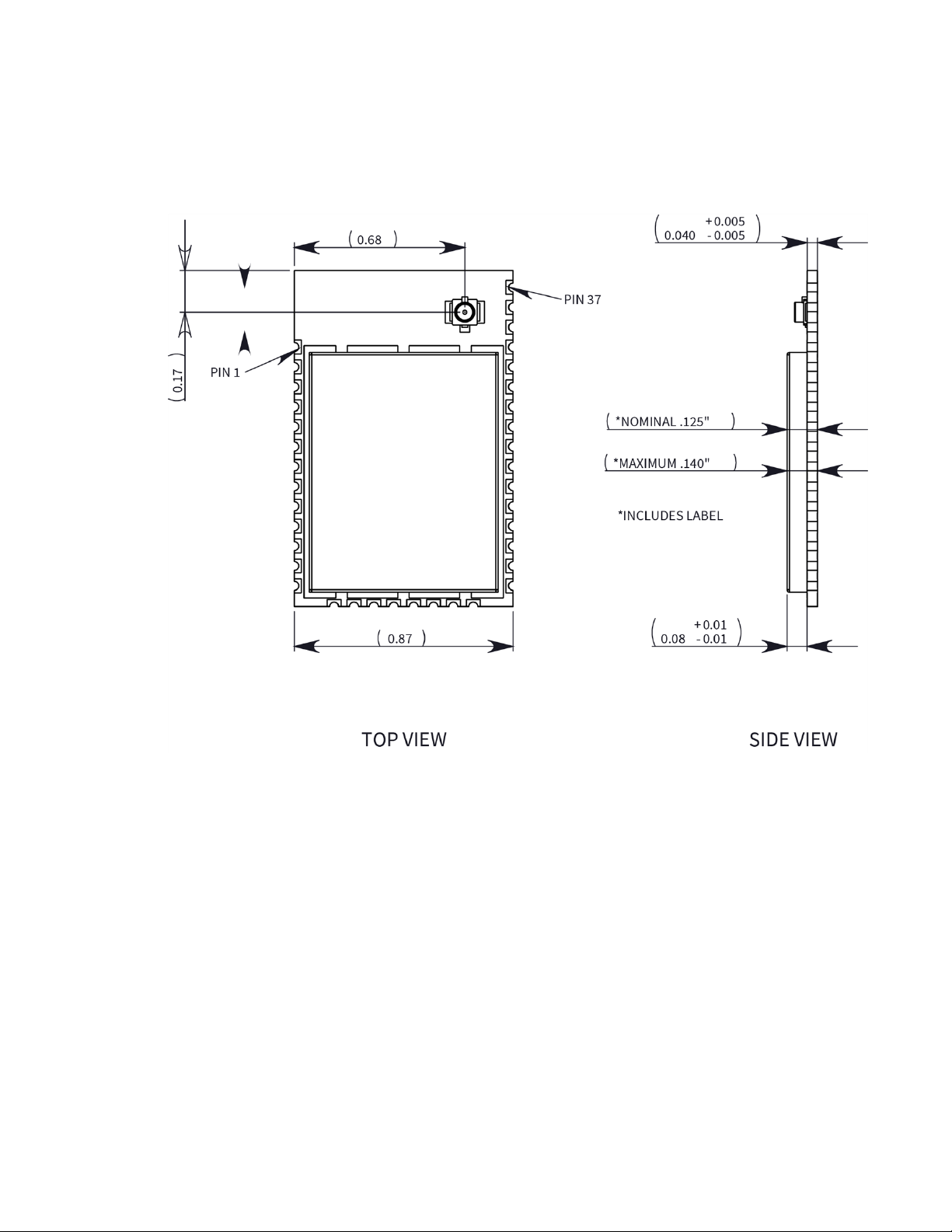
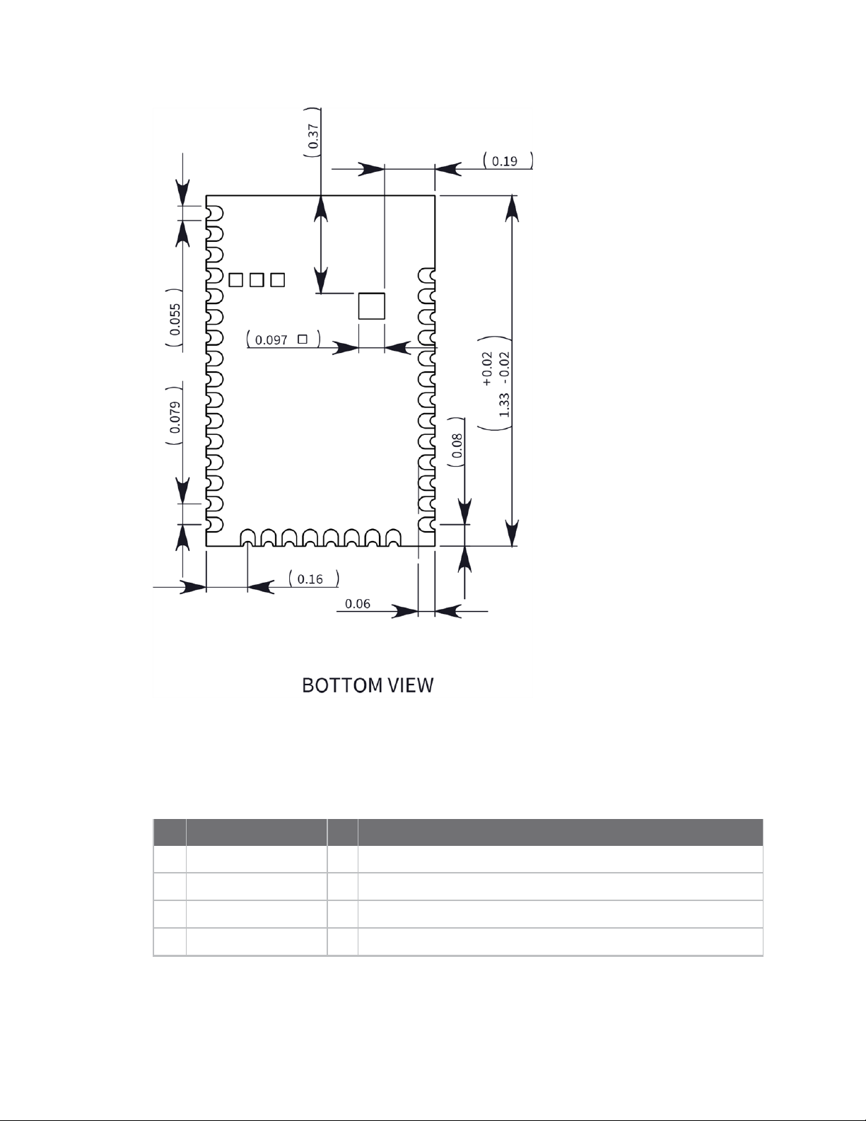
Mechanical drawings
The following images show the XTC mechanical drawings. The XTC has the same form factor as other
Digi surface-mount (SMT) XBee devices, except there is an additional copper ground pad on the
bottom.
XBee®/XBee-PRO XTend Compatible (XTC) DigiMesh RF Module User Guide
17
Page 18
Hardware Pin signals
Pin signals
The following table describes the pin signals. Low-asserted signals have a horizontal line over the
signal name.
Pin Designation I/O Function
1 GND - Ground
2 VCC I Power supply
3 DOUT O UART Data Out
4 DIN I UART Data In
XBee®/XBee-PRO XTend Compatible (XTC) DigiMesh RF Module User Guide
18
Page 19

Hardware Pin signals
Pin Designation I/O Function
5 GPO2/RX LED O General Purpose Output / RX LED
6 RESET I Module reset
7 RSSI O RX Signal Strength Indicator
8 - Disabled
9 Reserved NC Do not connect
10 SLEEP (DTR) I Pin Sleep Control Line
11 GND - Ground
12 - Disabled
13 GND - Ground
14 - Disabled
15 - Disabled
16 - Disabled
17 - Disabled
18 Reserved NC Do not connect
19 Reserved NC Do not connect
20 Reserved NC Do not connect
21 Reserved NC Do not connect
22 GND - Ground
23 Reserved NC Do not connect
24 - Disabled
25 GPO1/CTS /RS-485
TX_EN
26 ON/SLEEP O Module sleep status indicator
27 Reserved NC Do not connect
28 TX _PWR O Transmit power
29 RTS I Request-to-Send Flow Control
30 - Disabled
O General Purpose Output / Clear-to-Send Flow Control / RS-485
Transmit Enable
31 - Disabled
32 - Disabled
XBee®/XBee-PRO XTend Compatible (XTC) DigiMesh RF Module User Guide
19
Page 20

Hardware Pin signals
Pin Designation I/O Function
33 Reserved NC
34 Reserved NC
35 GND - Ground
36 RF I/O RF I/O for RF pad variant
37 NC NC
38 GND - Ground pad for heat transfer to host PCB
Note If you integrate the XTC RF Module with a host PC board, leave all lines you do not use
disconnected (floating).
Recommended pin connections
The only required pin connections are VCC, GND, DOUT and DIN. To support serial firmware updates,
you should connect VCC, GND, DOUT, DIN, RTS, and SLEEP (DTR).
XBee®/XBee-PRO XTend Compatible (XTC) DigiMesh RF Module User Guide
20
Page 21

Modes
The XTC RF Module is in Receive Mode when it is not transmitting data. The device shifts into the
other modes of operation under the following conditions:
n Transmit mode (Serial data in the serial receive buffer is ready to be packetized)
n Sleep mode
n Command Mode (Command mode sequence is issued (not available when using the SPI port))
Transparent and API operating modes 22
Receive mode 22
Transmit mode 23
Command mode 23
XBee®/XBee-PRO XTend Compatible (XTC) DigiMesh RF Module User Guide
21
Page 22

Modes Transparent and API operating modes
Transparent and API operating modes
The firmware operates in several different modes. Two top-level modes establish how the device
communicates with other devices through its serial interface: Transparent operating mode and API
operating mode.
Transparent operating mode
Devices operate in this mode by default. The device acts as a serial line replacement when it is in
Transparent operating mode. The device queues all UART data it receives through the DIN pin for RF
transmission. When a device receives RF data, it sends the data out through the DOUT pin.
API operating mode
API operating mode is an alternative to Transparent operating mode. API mode is a frame-based
protocol that allows you to direct data on a packet basis. The device communicates UART data in
packets, also known as API frames. This mode allows for structured communications with computers
and microcontrollers.
The advantages of APIoperating mode include:
n It is easier to send information to multiple destinations
n The host receives the source address for each received data frame
n You can change parameters without entering Command mode
n You can query or set a configuration parameter while a pending command—for example ND—is
in progress. This cannot be done in Command mode.
For more information, see API frame specifications.
Receive mode
This is the default mode for the XTC RF Module. The device is in Receive mode when it is not
transmitting data. If a destination node receives a valid RF packet, the destination node transfers the
data to its serial transmit buffer.
If a destination node receives a valid RF packet, the destination node transfers the data to its serial
transmit buffer. For the serial interface to report received data on the RF network, that data must
meet the following criteria:
n Network ID match
n Channel match
n Address match
XBee®/XBee-PRO XTend Compatible (XTC) DigiMesh RF Module User Guide
22
Page 23
Modes Transmit mode
Transmit mode
When DigiMesh data is transmitted from one node to another, the destination node transmits a
network-level acknowledgment back across the established route to the source node. This
acknowledgment packet indicates to the source node that the destination node received the data
packet. If the source node does not receive a network acknowledgment, it retransmits the data.
For more information, see Data transmission and routing.
Command mode
Command mode is a state in which the firmware interprets incoming characters as commands. It
allows you to modify the device’s configuration using parameters you can set using AT
commands.When you want to read or set any parameter of the XTC RF Module using this mode, you
have to send an AT command.Every AT command starts with the lettersATfollowed by the two
characters that identify the command and then by some optional configuration values.
The operating modes of the XTC RF Module are controlled by the AP (API Enable) setting,
butCommand mode is always available as a mode thedevice can enter while configured for any of the
operating modes.
Command mode is available on the UART interface for all operating modes. You cannot use the SPI
interface to enter Command mode.
Enter Command mode
To get a device to switch into Command mode, you must issue the following sequence:+++within one
second. There must be at least one second preceding and following the+++sequence. Both the
command character (CC) and the silence before and after the sequence (GT) are configurable. When
the entrance criteria are met the device responds with OK\r on UART signifying that it has entered
Command mode successfully and is ready to start processing AT commands.
If configured to operate in Transparent operating mode, when entering Command mode the XTC RF
Module knows to stop sending data and start accepting commands locally.
XBee®/XBee-PRO XTend Compatible (XTC) DigiMesh RF Module User Guide
23
Page 24
Modes Command mode
Note Do not press Return or Enter after typing+++because it interrupts the guard time silence and
prevents you from entering Command mode.
When the device is in Command mode, it listens for user input and is able to receive AT commands on
the UART. IfCTtime (default is 10 seconds) passes without any user input, the device drops out of
Command mode and returns to the previous operating mode. You can force the device to leave
Command mode by sending CN (Exit Command Mode).
You can customize the command character, the guard times and the timeout in the device’s
configuration settings. For more information, seeCC (Command Character),CT (Command Mode
Timeout)andGT (Guard Times).
When the device is in Command mode, it listens for user input and is able to receive AT commands on
the UART. IfCTtime (default is 10 seconds) passes without any user input, the device drops out of
Command mode and returns to the previous operating mode. You can force the device to leave
Command mode by sending CN (Exit Command Mode).
You can customize the command character, the guard times and the timeout in the device’s
configuration settings. For more information, seeCC (Command Sequence Character),CT (Command
Mode Timeout)andGT (Guard Times).
Troubleshooting
Failure to enter Command mode is often due to baud rate mismatch. Ensure that the baud rate of the
connection matches the baud rate of the device. By default, BD (Baud Rate) = 3 (9600 b/s).
Failure to enter Command mode is often due to baud rate mismatch. Ensure that the baud rate of the
connection matches the baud rate of the device. By default, BD (Interface Data Rate) = 3 (9600 b/s).
There are two alternative ways to enter Command mode:
n A serial break for six seconds enters Command mode. You can issue the "break" command
from a serial console, it is often a button or menu item.
n Asserting DIN (serial break) upon power up or reset enters Command mode. XCTU guides you
through a reset and automatically issues the break when needed.
Both of these methods temporarily set the device's baud rate to 9600 and return anOKon the UART
to indicate that Command mode is active. When Command mode exits, the device returns to normal
operation at the baud rate that BDis set to.
Send AT commands
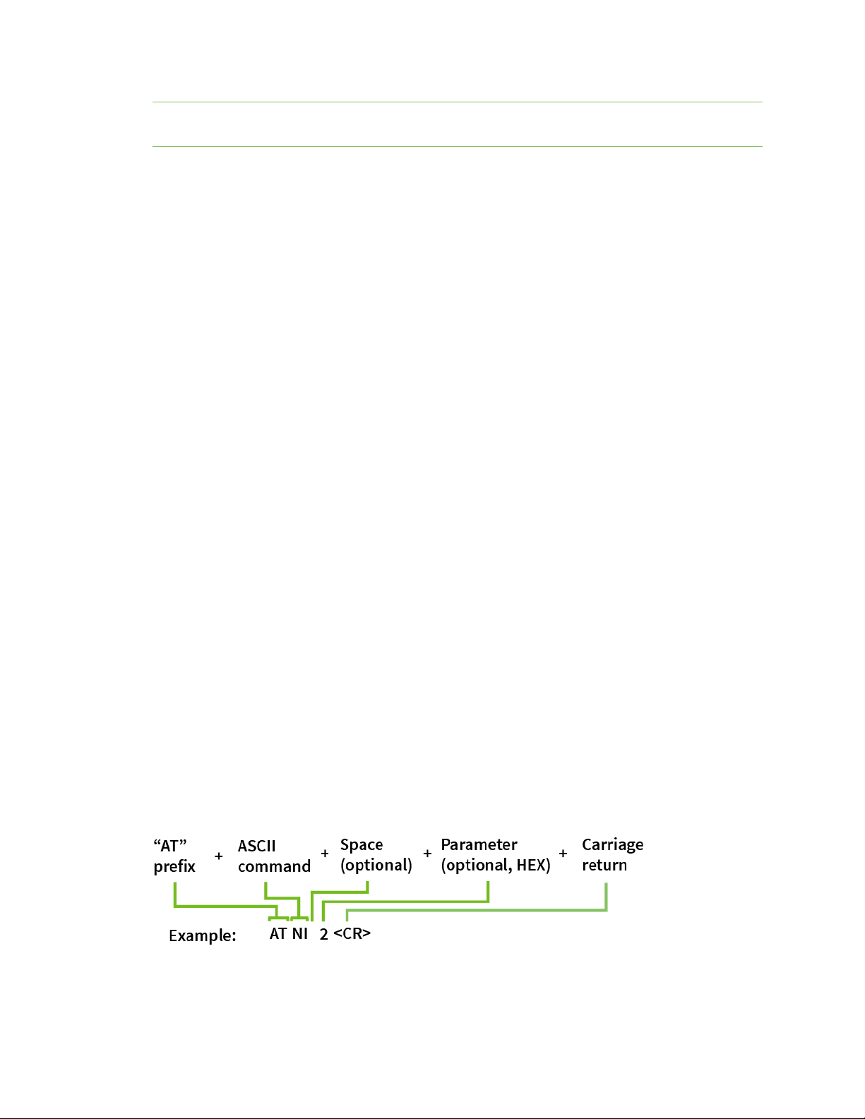
Once the device enters Command mode, use the syntax in the following figure to send AT commands.
Every AT command starts with the lettersAT, which stands for "attention." TheATis followed by two
characters that indicate which command is being issued, then by some optional configuration values.
To read a parameter value stored in the device’s register, omit the parameter field.
The preceding example changes NI (Node Identifier) to My XBee.
XBee®/XBee-PRO XTend Compatible (XTC) DigiMesh RF Module User Guide
24
Page 25

Modes Command mode
Multiple AT commands
You can send multiple AT commands at a time when they are separated by a comma in Command
mode; for example,ATNIMy XBee,AC<cr>.
The preceding example changes theNI (Node Identifier) to My XBeeand makes the setting active
through AC (Apply Changes).
Parameter format
Refer to the list of AT commands for the format of individual AT command parameters. Valid formats
for hexidecimal values include with or without a leading0xfor exampleFFFFor0xFFFF.
Response to AT commands
When using AT commands to set parameters the XTC RF Module responds with OK<cr> if successful
and ERROR<cr> if not.
For devices with a file system:
ATAP1<cr>
OK<cr>
When reading parameters, the device returns the current parameter value instead of anOKmessage.
ATAP<cr>
1<cr>
Apply command changes
Any changes you make to the configuration command registers using AT commands do not take effect
until you apply the changes. For example, if you send theBDcommand to change the baud rate, the
actual baud rate does not change until you apply the changes. To apply changes:
1. Send AC (Apply Changes).
2. Send WR (Write).
or:
3. Exit Command mode.
Make command changes permanent
Send a WR (Write) command to save the changes. WR writes parameter values to non-volatile memory
so that parameter modifications persist through subsequent resets.
Send as RE (Restore Defaults) to wipe settings saved using WR back to their factory defaults.
Note You still have to use WR to save the changes enacted with RE.
Exit Command mode
1. Send CN (Exit Command Mode) followed by a carriage return.
or:
2. If the device does not receive any valid AT commands within the time specified byCT
(Command Mode Timeout), it returns to Transparent or API mode. The default Command mode
timeout is10seconds.
XBee®/XBee-PRO XTend Compatible (XTC) DigiMesh RF Module User Guide
25
Page 26

Modes Command mode
For an example of programming the device using AT Commands and descriptions of each configurable
parameter, see AT commands.
1. Send CN (Exit Command Mode) followed by a carriage return.
or:
2. If the device does not receive any valid AT commands within the time specified byCT
(Command Mode Timeout), it returns to Transparent or API mode. The default Command mode
timeout is10seconds.
For an example of programming the device using AT Commands and descriptions of each configurable
parameter, see Commands.
XBee®/XBee-PRO XTend Compatible (XTC) DigiMesh RF Module User Guide
26
Page 27
Operation
WARNING! When operating at 1 W power output, observe a minimum separation distance
of 6 ft (2 m) between devices. Transmitting in close proximity of other devices can damage
the device's front end.
Serial interface 28
XBee®/XBee-PRO XTend Compatible (XTC) DigiMesh RF Module User Guide
27
Page 28
Operation Serial interface
Serial interface
The XTC RF Module provides a serial interface to an RF link. The XTC RF Module converts serial data to
RF data and sends that data to any over-the-air compatible device in an RF network. The device can
communicate through its serial port with any logic and voltage compatible universal asynchronous
receiver/transmitter (UART), or through a level translator to any serial device.
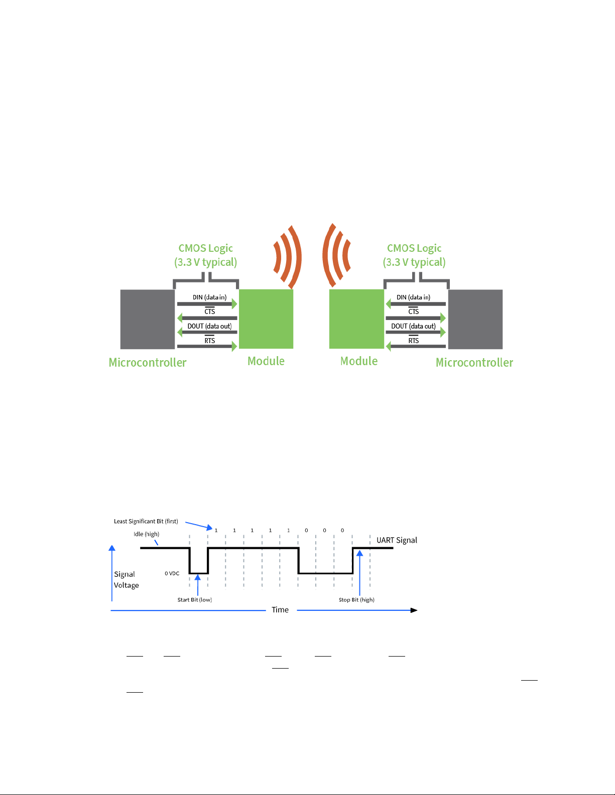
UART data flow
Devices that have a UART interface connect directly to the pins of the XTC RF Module as shown in the
following figure. The figure shows system data flow in a UART-interfaced environment. Low-asserted
signals have a horizontal line over the signal name.
Serial data
A device sends data to the XTC RF Module's UART through pin 4 DIN as an asynchronous serial signal.
When the device is not transmitting data, the signals should idle high.
For serial communication to occur, you must configure the UART of both devices (the microcontroller
and the XTC RF Module) with compatible settings for the baud rate, parity, start bits, stop bits, and
data bits.
Each data byte consists of a start bit (low), 8 data bits (least significant bit first) and a stop bit (high).
The following diagram illustrates the serial bit pattern of data passing through the device. The
diagram shows UART data packet 0x1F (decimal number 31) as transmitted through the device.
Serial flow control
The RTS and CTS device pins provide RTS and/or CTS flow control. CTS flow control signals the host to
stop sending serial data to the device. RTS flow control lets the host signal the device so it will not
send the data in the serial transmit buffer out the UART. Use the D6 and D7 commands to enable RTS
and CTS flow control.
XBee®/XBee-PRO XTend Compatible (XTC) DigiMesh RF Module User Guide
28
Page 29

Operation Serial interface
CTS flow control
CTS flow control is enabled by default; you can disable it with the D7 command. When the serial
receive buffer fills with the number of bytes specified by the FT parameter, the device de-asserts CTS
(sets it high) to signal the host device to stop sending serial data. The device re-asserts CTS when less
than FT-16 bytes are in the UART receive buffer; for more information, see FT (Flow Control
Threshold).
RTS flow control
If you send the D6 command to enable RTS flow control, the device does not send data in the serial
transmit buffer out the DOUT pin as long as RTS is de-asserted (set high). Do not de-assert RTS for
long periods of time or the serial transmit buffer will fill. If the device receives an RF data packet and
the serial transmit buffer does not have enough space for all of the data bytes, it discards the entire
RF data packet.
XBee®/XBee-PRO XTend Compatible (XTC) DigiMesh RF Module User Guide
29
Page 30

Networking methods
The MAC and PHY layers 31
64-bit addresses 31
Make a unicast transmission 32
Delivery methods 32
XBee®/XBee-PRO XTend Compatible (XTC) DigiMesh RF Module User Guide
30
Page 31

Networking methods The MAC and PHY layers
The MAC and PHY layers
Most network protocols use the concept of layers to separate different components and functions
into independent modules that developers can assemble in different ways.
The PHY layer defines the physical and electrical characteristics of the network. It is responsible for
managing the hardware that modulates and demodulates the RF bits.
The MAC layer is responsible for sending and receiving RF frames. As part of each packet, there is a
MAC layer data header that has addressing information as well as packet options. This layer
implements packet acknowledgments (ACKs), packet tracking to eliminate duplicates, and so forth.
n When a device is transmitting, it cannot receive packets.
n When a device is not sleeping, it is either receiving or transmitting.
n There are no beacons or master/slave requirements in the design of the MAC/PHY.
The XTC RF Module uses a patented method for scanning and finding a transmission. When a device
transmits, it sends out a repeated preamble pattern, a MAC header, optionally a network header,
followed by packet data. A receiving device is able to scan all the channels to find a transmission
during the preamble, then once it has locked into that channel it attempts to receive the whole
packet.
The following table shows the AT commands related to the MAC/PHY layers.
AT
command Function
HP Change HP (Preamble ID) to make it so a group of devices will not interfere with
another group of devices in the same vicinity. The advantage of changing this
parameter is that a receiving device will not lock into a transmission of a transmitting
device that does not have the same Preamble ID.
ID Change ID (Network ID) to further keep devices from interfering with each other. The
device matches this ID after it matches the preamble pattern and after it receives the
MAC header.
A unique network identifier distinguishes each network. For devices to communicate,
they must be configured with the same network identifier. The ID parameter allows
multiple networks to co-exist on the same physical channel.
PL Sets the transmit (TX) power level. You can reduce the power level from the maximum
to reduce current consumption or for testing. This comes at the expense of reduced
radio range.
RR
MT
Specifies the number of times a sending device attempts to get an ACK from a
destination device when it sends a unicast packet.
Specifies the number of times that a device repeatedly transmits a broadcast packet.
This adds redundancy, which improves reliability.
64-bit addresses
We assign each device a unique IEEE 64-bit address at the factory. When a device is in API operating
mode and it sends a packet, this is the source address that the receiving device returns.
XBee®/XBee-PRO XTend Compatible (XTC) DigiMesh RF Module User Guide
31
Page 32

Networking methods Make a unicast transmission
n Use the SH and SLcommands to read this address.
n The form of the address is: 0x0013A2XXXXXXXXXX.
n The first six digits are the Digi Organizationally Unique Identifier (OUI).
n The broadcast address is 0x000000000000FFFF.
Make a unicast transmission
To transmit to a specific device in Transparent operating mode:
n Set DH:DL to the SH:SL of the destination device.
To transmit to a specific device in API operating mode:
n In the 64-bit destination address of the API frame, enter the SH:SL address of the destination
device.
Delivery methods
The TO (Transmit Options) command sets the default delivery method that the device uses when in
Transparent mode. In API mode, the TxOptions field of the API frame overrides the TO command, if
non-zero.
The XTC RF Module supports three delivery methods:
n Point-to-multipoint (TO = 0x40).
n Repeater (directed broadcast) (TO = 0x80).
n DigiMesh (TO = 0xC0).
Point to Point / Point to Multipoint (P2MP)
This delivery method does not use a network header, only the MAC header.
In P2MP, the sending devices always send all messages directly to the destination. Other nodes do not
repeat the packet. The sending device only delivers a P2MP unicast directly to the destination device,
which must be in range of the sending device.
The XTC RF Module uses patented technology that allows the destination device to receive unicast
transmissions directed to it, even when there is a large amount of traffic. This works best if you keep
broadcast transmissions to a minimum.
A sending node repeats a P2MP broadcast transmission MT+1 times, but the receiving nodes do not
repeat it, so like a unicast transmission, the receiving device must be in range.
All devices that receive a P2MP broadcast transmission output the data through the serial port.
Repeater/directed broadcast
All of the routers in a network receive and repeat directed broadcast transmissions. Because it does
not use ACKs, the originating node sends the broadcast multiple times. By default a broadcast
transmission is sent four times—the extra transmissions become automatic retries without
acknowledgments. This results in all nodes repeating the transmission four times. Sending frequent
broadcast transmissions can quickly reduce the available network bandwidth, so use broadcast
transmissions sparingly.
XBee®/XBee-PRO XTend Compatible (XTC) DigiMesh RF Module User Guide
32
Page 33

Networking methods Delivery methods
MAC layer
The MAC layer is the building block that is used to build repeater capability. To implement Repeater
mode, we use a network layer header that comes after the MAC layer header in each packet. In this
network layer there is additional packet tracking to eliminate duplicate broadcasts.
In this delivery method, the device sends both unicast and broadcast packets out as broadcasts that
are always repeated. All repeated packets are sent to every device. The devices that receive the
broadcast send broadcast data out their serial port.
When a device sends a unicast, it specifies a destination address in the network header. Then, only the
device that has the matching destination address sends the unicast out its serial port. This is called a
directed broadcast.
Any node that has a CE parameter set to router rebroadcasts the packet if its BH (broadcast hops) or
broadcast radius values are not depleted. If a node has already seen a repeated broadcast, it ignores
the broadcast.
The NH parameter sets the maximum number of hops that a broadcast transmission is repeated. The
device always uses the NH value unless you specify a BH value that is smaller.
By default the CE parameter is set to route all broadcasts. As such, all nodes that receive a repeated
packet will repeat it. If you change the CE parameter, you can limit which nodes repeat packets, which
helps dense networks from becoming overly congested while packets are being repeated.
Transmission timeout calculations for Repeater/directed broadcast mode are the same as for
DigiMesh broadcast transmissions.
DigiMesh networking
A mesh network is a topology in which each node in the network is connected to other nodes around
it. Each node cooperates in transmitting information. Mesh networking provides these important
benefits:
n Routing. With this technique, the message is propagated along a path by hopping from node to
node until it reaches its final destination.
n Ad-hoc network creation. This is an automated process that creates an entire network of
nodes on the fly, without any human intervention.
n Self-healing. This process automatically figures out if one or more nodes on the network is
missing and reconfigures the network to repair any broken routes.
n Peer-to-peer architecture. No hierarchy and no parent-child relationships are needed.
n Quiet protocol. Routing overhead will be reduced by using a reactive protocol similar to AODV.
n Route discovery. Rather than maintaining a network map, routes will be discovered and
created only when needed.
n Selective acknowledgments. Only the destination node will reply to route requests.
n Reliable delivery. Reliable delivery of data is accomplished by means of acknowledgments.
n Sleep modes. Low power sleep modes with synchronized wake are supported with variable
sleep and wake times.
XBee®/XBee-PRO XTend Compatible (XTC) DigiMesh RF Module User Guide
33
Page 34

Networking methods Delivery methods
With mesh networking, the distance between two nodes does not matter as long as there are enough
nodes in between to pass the message along. When one node wants to communicate with another,
the network automatically calculates the best path.
A mesh network is also reliable and offers redundancy. For example, If a node can no longer operate
because it has been removed from the network or because a barrier blocks its ability to communicate,
the rest of the nodes can still communicate with each other, either directly or through intermediate
nodes.
Note Mesh networks use more bandwidth for administration and therefore have less available for
payloads.
Unicast addressing
When devices transmit using DigiMesh unicast, the network uses retries and acknowledgments
(ACKs)for reliable data delivery. In a retry and acknowledgment scheme, for every data packet that a
device sends, the receiving device must send an acknowledgment back to the transmitting device to
let the sender know that the data packet arrived at the receiver. If the transmitting device does not
receive an acknowledgment then it re-sends the packet. It sends the packet a finite number of times
before the system times out.
The MR (Mesh Network Retries) parameter determines the number of mesh network retries. The
sender device transmits RF data packets up to MR + 1 times across the network route, and the
receiver transmits ACKs when it receives the packet. If the sender does not receive a network ACK
within the time it takes for a packet to traverse the network twice, the sender retransmits the
packet.
To send unicast messages while in Transparent operating mode, set the DH and DL on the
transmitting device to match the corresponding SH and SL parameter values on the receiving device.
Routing
A device within a mesh network determines reliable routes using a routing algorithm and table. The
routing algorithm uses a reactive method derived from Ad-hoc On-demand Distance Vector (AODV).
The firmware uses an associative routing table to map a destination node address with its next hop. A
device sends a message to the next hop address, and the message either reaches its destination or
forwards to an intermediate router that routes the message on to its destination.
XBee®/XBee-PRO XTend Compatible (XTC) DigiMesh RF Module User Guide
34
Page 35

Networking methods Delivery methods
If a message has a broadcast address, it is broadcast to all neighbors, then all routers that receive the
message rebroadcast the message MT+1 times. Eventually, the message reaches the entire network.
Packet tracking prevents a node from resending a broadcast message more than MT+1 times. This
means that a node that relays a broadcast will only relay it after it receives it the first time and it will
discard repeated instances of the same packet.
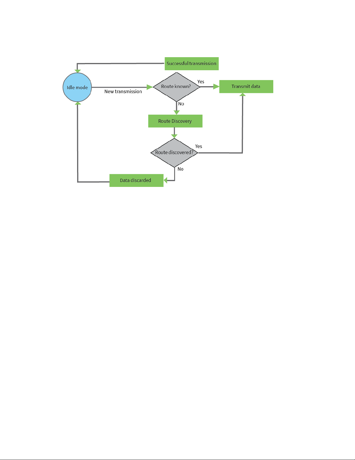
Route discovery
Route discovery is a process that occurs when:
1. The source node does not have a route to the requested destination.
2. A route fails. This happens when the source node uses up its network retries without receiving
an ACK.
Route discovery begins by the source node broadcasting a route request (RREQ). We call any router
that receives the RREQ and is not the ultimate destination, an intermediate node.
Intermediate nodes may either drop or forward a RREQ, depending on whether the new RREQ has a
better route back to the source node. If so, the node saves, updates and broadcasts the RREQ.
When the ultimate destination receives the RREQ, it unicasts a route reply (RREP) back to the source
node along the path of the RREQ. It does this regardless of route quality and regardless of how many
times it has seen an RREQ before.
This allows the source node to receive multiple route replies. The source node selects the route with
the best round trip route quality, which it uses for the queued packet and for subsequent packets with
the same destination address.
Transmission timeouts
When a device in API operating mode receives a Transmit Request (0x10, 0x11) frame, or a device in
Transparent operating mode meets the packetization requirements (RO, RB), the time required to
route the data to its destination depends on:
n A number of configured parameters.
n Whether the transmission is a unicast or a broadcast.
n If the route to the destination address is known.
Timeouts or timing information is provided for the following transmission types:
n Broadcast transmission
n Unicast transmission on a known route
n Unicast transmission on an unknown route
n Unicast transmission on a broken route
Note The timeouts in this documentation are theoretical timeouts and are not precisely accurate.
Your application should pad the calculated maximum timeouts by a few hundred milliseconds. When
you use API operating mode, use Extended Transmit Status - 0x8B as the primary method to
determine if a transmission is complete.
Unicast one hop time
unicastOneHopTime is a building block of many of the following calculations. It represents the amount
of time it takes to send a unicast transmission between two adjacent nodes. The amount of time
depends on the %H parameter.
XBee®/XBee-PRO XTend Compatible (XTC) DigiMesh RF Module User Guide
35
Page 36

Networking methods Delivery methods
Transmit a broadcast
All of the routers in a network must relay a broadcast transmission.
The maximum delay occurs when the sender and receiver are on the opposite ends of the network.
The NH and %H parameters define the maximum broadcast delay as follows:
BroadcastTxTime = NH * NN * %8
Unless BH < NH, in which case the formula is:
BroadcastTxTime = BH * NN * %8
Transmit a unicast with a known route
When a device knows a route to a destination node, the transmission time is largely a function of the
number of hops and retries. The timeout associated with a unicast assumes that the maximum
number of hops is necessary, as specified by the NH command.
You can estimate the timeout in the following manner:
knownRouteUnicastTime=2*NH*MR*unicastOneHopTime
Transmit a unicast with an unknown route
If the transmitting device does not know the route to the destination, it begins by sending a route
discovery. If the route discovery is successful, then the transmitting device transmits data. You can
estimate the timeout associated with the entire operation as follows:
unknownRouteUnicastTime=BroadcastTxTime+
(NH*unicastOneHopTime)+knownRouteUnicastTime
Transmit a unicast with a broken route
If the route to a destination node changes after route discovery completes, a node begins by
attempting to send the data along the previous route. After it fails, it initiates route discovery and,
when the route discovery finishes, transmits the data along the new route. You can estimate the
timeout associated with the entire operation as follows:
brokenRouteUnicastTime=BroadcastTxTime+(NH*unicastOneHopTime)+
(2*knownRouteUnicastTime)
XBee®/XBee-PRO XTend Compatible (XTC) DigiMesh RF Module User Guide
36
Page 37

AT commands
Addressing commands 38
Command mode options 41
Diagnostic commands 42
Firmware commands 45
I/O settings commands 47
I/O diagnostic commands 48
MAC/PHY commands 48
Network commands 50
Security commands 52
Serial interfacing commands 53
Special commands 56
XBee®/XBee-PRO XTend Compatible (XTC) DigiMesh RF Module User Guide
37
Page 38

AT commands Addressing commands
Addressing commands
The following AT commands are addressing commands.
CI (Cluster ID)
The application layer cluster ID value. The device uses this value as the cluster ID for all data
transmissions.
If you set this value to 0x12 (loopback Cluster ID), the destination node echoes any transmitted
packet back to the source device.
Parameter range
0 - 0xFFFF
Default
0x11 (Transparent data cluster ID)
DH (Destination Address High)
Set or read the upper 32 bits of the 64-bit destination address. When you combine DH with DL, it
defines the destination address that the device uses for transmissions in Transparent mode.
The destination address is also used for I/O sampling in both Transparent and API modes.
To transmit using a 16-bit address, set DH to 0 and DL less than 0xFFFF.
0x000000000000FFFF is the broadcast address.
Parameter range
0 - 0xFFFFFFFF
Default
0
DL (Destination Address Low)
Set or display the lower 32 bits of the 64-bit destination address. When you combine DH with DL, it
defines the destination address that the device uses for transmissions in Transparent mode.
The destination address is also used for I/O sampling in both Transparent and API modes.
0x000000000000FFFF is the broadcast address.
Parameter range
0 - 0xFFFFFFFF
Default
0xFFFF
NI (Node Identifier)
Stores the node identifier string for a device, which is a user-defined name or description of the
device. This can be up to 20 ASCII characters.
XBee®/XBee-PRO XTend Compatible (XTC) DigiMesh RF Module User Guide
38
Page 39

AT commands Addressing commands
n XCTU prevents you from exceeding the string limit of 20 characters for this command. If you
are using another software application to send the string, you can enter longer strings, but the
software on the device returns an error.
Parameter range
A string of case-sensitive ASCII printable characters from 0 to 20 bytes in length. A carriage return
or a comma automatically ends the command.
Default
0x20 (an ASCII space character)
NO (Network Discovery Options)
Set or read the network discovery options value for the ND (Network Discovery) command on a
particular device. The options bit field value changes the behavior of the ND command and what
optional values the local device returns when it receives an ND command or API Node Identification
Indicator (0x95)frame.
Use NOto suppress or include a self-response to ND (Node Discover) commands. When NO bit 1 = 1, a
device performing a Node Discover includes a response entry for itself.
Parameter range
0x0 - 0x7 (bit field)
Bit field
Option Description
0x01
0x02
0x04
Default
Append the DD (Digi Device Identifier) value to ND responses or API node identification
frames.
Local device sends ND response frame out the serial interface when ND is issued.
Append the RSSI of the last hop to ND, FN, and responses or API node identification
frames.
0x0
NT (Network Discovery Back-off)
Sets or displays the network discovery back-off parameter for a device. This sets the maximum value
for the random delay that the device uses to send network discovery responses.
Parameter range
0x20 - 0x2EE0 (x 100 ms)
Default
0x82 (13 seconds)
XBee®/XBee-PRO XTend Compatible (XTC) DigiMesh RF Module User Guide
39
Page 40

AT commands Addressing commands
SH (Serial Number High)
Displays the upper 32 bits of the unique IEEE 64-bit extended address assigned to the XTend in the
factory.
The 64-bit source address is always enabled. This value is read-only and it never changes.
Parameter range
0 - 0xFFFFFFFF [read-only]
Default
Set in the factory
SL (Serial Number Low)
Displays the lower 32 bits of the unique IEEE 64-bit RF extended address assigned to the XTend in the
factory.
The 64-bit source address is always enabled. This value is read-only and it never changes.
Parameter range
0 - 0xFFFFFFFF [read-only]
Default
Set in the factory
TO (Transmit Options)
The bitfield that configures the transmit options for Transparent mode.
The device's transmit options. The device uses these options for all transparent transmissions. API
transmissions can override this using the TxOptions field in the API frame.
Parameter range
0 - 0xFF
Bit field:
Bit Meaning Description
6,7 Delivery method
5 Reserved <set this bit to 0>
4 Reserved <set this bit to 0>
3 Trace Route Enable a Trace Route on all DigiMesh API packets
b’00 = <invalid option>
b’01 = Point-multipoint (0x40)
b'10 = Directed Broadcast (0x80)
b’11 = DigiMesh (0xC0)
2 NACK Enable a NACK messages on all DigiMesh API packets
1 Disable RD Disable Route Discovery on all DigiMesh unicasts
0 Disable ACK Disable acknowledgments on all unicasts
XBee®/XBee-PRO XTend Compatible (XTC) DigiMesh RF Module User Guide
40
Page 41

AT commands Command mode options
n Bits 6 and 7 cannot be set to DigiMesh on the 10k build.
n Bits 4 and 5 must be set to 0.
n Bits 1, 2, and 3 cannot be set on the 10k build.
When you set BR to 0 the TO option has the DigiMesh and Repeater mode disabled automatically.
Default
0xC0
Command mode options
The following commands are Command mode option commands.
CC (Command Character)
The character value the device uses to enter Command mode.
The default value (0x2B) is the ASCII code for the plus (+) character. You must enter it three times
within the guard time to enter Command mode. To enter Command mode, there is also a required
period of silence before and after the command sequence characters of the Command mode
sequence (GT + CC + GT). The period of silence prevents inadvertently entering Command mode.
Parameter range
0 - 0xFF
Recommended: 0x20 - 0x7F (ASCII)
Default
0x2B (the ASCII plus character:+)
CT (Command Mode Timeout)
Sets or displays the Command mode timeout parameter. If a device does not receive any valid
commands within this time period, it returns to Idle mode from Command mode.
Parameter range
2 - 0x1770 (x 100 ms)
Default
0x64 (10 seconds)
GT (Guard Times)
Set the required period of silence before and after the command sequence characters of the
Command mode sequence (GT + CC + GT). The period of silence prevents inadvertently entering
Command mode.
Parameter range
0x2 - 0xCE4 (x 1 ms)
Default
0x3E8 (one second)
XBee®/XBee-PRO XTend Compatible (XTC) DigiMesh RF Module User Guide
41
Page 42

AT commands Diagnostic commands
Diagnostic commands
The following AT commands are diagnostic commands. Diagnostic commands are typically volatile and
will not persist across a power cycle.
%H (MAC Unicast One Hop Time)
The MAC unicast one hop time timeout in milliseconds. If you change the MAC parameters it can
change this value.
Parameter range
[read-only]
Default
N/A
0x267
%V (Board Voltage)
Reads the supply voltage to the module's VCC (pin 2).
The conversion of the hex value returned by %V to Volts is VAL/65536 = Volts.
Example:
2.8 VDC = 2.8 * 65536 = 0x2CCCD
3.3 VDC = 3.3 * 65536 = 0x34CCD
Parameter range
[read-only]:
0x26666 - 0x39999 (2.40 to 3.60 V)
Default
N/A
%8 (MAC Broadcast One Hop Time)
Parameter range
[read-only]
Default
N/A
BC (Bytes Transmitted)
The number of RF bytes transmitted. The firmware counts every byte of every packet, including
MAC/PHY headers and trailers. The purpose of this count is to estimate battery life by tracking time
spent performing transmissions.
This number rolls over to 0 from 0xFFFF.
You can reset the counter to any unsigned 16-bit value by appending a hexadecimal parameter to the
command.
XBee®/XBee-PRO XTend Compatible (XTC) DigiMesh RF Module User Guide
42
Page 43

AT commands Diagnostic commands
Parameter range
0 - 0xFFFF
Default
0
DB (Last Packet RSSI)
Reports the RSSI in -dBm of the last received RF data packet. DB returns a hexadecimal value for the dBm measurement.
For example, if DB returns 0x60, then the RSSI of the last packet received was -96 dBm.
The RSSImeasurement is accurate from approximately -50 to -100 dBm.
DB only indicates the signal strength of the last hop. It does not provide an accurate quality
measurement for a multihop link.
If the XTC RF Module has been reset and has not yet received a packet, DB reports 0.
This value is volatile (the value does not persist in the device's memory after a power-up sequence).
Parameter range
0x28 - 0x6E (-40 dBm to -110 dBm) [read-only]
Default
0
EA (MAC ACK Failure Count)
This count increments whenever a MAC ACK timeout occurs on a MAC-level unicast. When the number
reaches 0xFFFF, the firmware does not count further events.
To reset the counter to any 16-bit unsigned value, append a hexadecimal parameter to the command.
This value is volatile (the value does not persist in the device's memory after a power-up sequence).
Parameter range
0 - 0xFFFF
Default
0
N/A
ER (Receive Count Error)
This count increments when a device receives a packet that contains integrity errors of some sort.
When the number reaches 0xFFFF, the firmware does not count further events.
To reset the counter to any 16-bit value, append a hexadecimal parameter to the command. This
value is volatile (the value does not persist in the device's memory after a power-up sequence).
Occasionally random noise can cause this value to increment.
The ER parameter is not reset by pin, serial port or cyclic sleep modes.
Default
0
XBee®/XBee-PRO XTend Compatible (XTC) DigiMesh RF Module User Guide
43
Page 44

AT commands Diagnostic commands
GD (Good Packets Received)
This count increments when a device receives a good frame with a valid MAC header on the RF
interface. Received MAC ACK packets do not increment this counter. Once the number reaches
0xFFFF, it does not count further events.
To reset the counter to any 16-bit unsigned value, append a hexadecimal parameter to the command.
This value is volatile (the value does not persist in the device's memory after a power-up sequence).
Parameter range
0 - 0xFFFF
Default
0
RC (RSSI for channel)
Reads and reports the power level on a given channel.
Channel must be provided as a parameter for this command or an ERROR will be received. Channels
for this command are zero based (0 = Channel 1, 0x31 = Channel 50)
Parameter range
[read-only]: 40 - 110 [dBm]
Default
N/A
R# (Reset Number)
Provides the reason for the last device reset.
Parameter range
0-5
Parameter Description
0 Power up reset
2 Watchdog reset
3 Software reset
4 Reset line reset
5 Brownout reset
Default
0
XBee®/XBee-PRO XTend Compatible (XTC) DigiMesh RF Module User Guide
44
Page 45

AT commands Firmware commands
TR (Transmit Error Count)
Parameter range
0 - 0xFFFF
Default
0
UA (Unicasts Attempted Count)
The number of unicast transmissions expecting an acknowledgment (when RR > 0).
This value is volatile (the value does not persist in the device's memory after a power-up sequence).
Parameter range
0 - 0xFFFF
Default
0
Firmware commands
The following AT commands are firmware commands.
CK (Configuration CRC)
Displays the cyclic redundancy check (CRC) of the current AT command configuration settings.
This command allows you to detect an unexpected configuration change on a device. Use the code
that the device returns to determine if a node has the configuration you want.
After a firmware update this command may return a different value.
Parameter range
N/A
Default
N/A
DD (Device Type Identifier)
Stores the Digi device type identifier value. Use this value to differentiate between multiple XBee
devices.
Parameter range
0 - 0xFFFFFFFF
Default
0x80000
NP (Maximum Packet Payload Bytes)
Reads the maximum number of RF payload bytes that you can send in a transmission.
XBee®/XBee-PRO XTend Compatible (XTC) DigiMesh RF Module User Guide
45
Page 46

AT commands Firmware commands
Using APS encryption (API transmit option bit enabled), reduces the maximum payload size by 9 bytes.
Using source routing (AR < 0xFF), further reduces the maximum payload size.
Note NP returns a hexadecimal value. For example, if NP returns 0x54, this is equivalent to 84 bytes.
Parameter range
0 - 0xFFFF (bytes) [read-only]
Default
N/A
HS (Hardware Series)
Read the device's hardware series number.
Parameter range
N/A
Default
0x0A00 - set in the firmware
HV (Hardware Version)
Display the hardware version number of the device.
Parameter range
0 - 0xFFFF [read-only]
Default
Set in firmware
VL (Firmware Version - Verbose)
Reads the verbose firmware version of the device.
Parameter range
Returns a string
Default
0
VR (Firmware Version)
Reads the firmware version on a device.
Parameter range
0 - 0xFFFFFFFF [read-only]
Default
Set in firmware
XBee®/XBee-PRO XTend Compatible (XTC) DigiMesh RF Module User Guide
46
Page 47

AT commands I/O settings commands
I/O settings commands
The following AT commands are I/O settings commands.
CD (GP02 Configuration)
Selects or reads the behavior of the GPO2 line (pin 5).
Parameter range
0 - 4
Parameter Configuration
0 RXLED
1 Static high
2 Static low
3 Reserved
4 RX LED (valid address only)
Default
2
CS (GP01 Configuration)
Sets or displays the behavior of the GPO1 line (pin 25). This output can provide RS-232 flow control and
controls the TX enable signal for RS-485 or RS-422 operations.
By default, GP01 provides RS-232 Clear-to-Send (CTS ) flow control.
Parameter range
0 - 4
Parameter Configuration
0 RS-232
1 RS-485 TX enable low
2 Static high
3 RS-485 TX enable high
4 Static low
Default
0
CTS
flow control
RP (RSSI PWM Timer)
Enables a pulse-width modulated (PWM) output on the RSSI pin (pin 7). We calibrate the pin to show
the difference between received signal strength and the sensitivity level of the device. PWM pulses
XBee®/XBee-PRO XTend Compatible (XTC) DigiMesh RF Module User Guide
47
Page 48

AT commands I/O diagnostic commands
vary from zero to 95 percent. Zero percent means the RF signal the device receives is at or below the
device's sensitivity level.
A non-zero value defines the time that PWM output is active with the RSSI value of the last RF packet
the device receives. After the set time when the device has not received RF packets, it sets the PWM
output low (0 percent PWM) until the device receives another RF packet. It also sets PWM output low
at power-up. A parameter value of 0xFF permanently enables PWM output and always reflects the
value of the last received RF packet.
Parameter range
0 - 0xFF [x 100 ms]
Default
0x28 (4 seconds)
RT (GPI1 Configuration)
Sets or displays the behavior of the GPI1 pin (pin 29) of the device. You can configure the pin to enable
RTS flow control.
Parameter range
0 - 2
Parameter Configuration
0 Disabled
1
2
Default
0 (disabled)
I/O diagnostic commands
The following AT commands are I/O diagnostic commands.
TP (Board Temperature)
The current module temperature in degrees Celsius in 8-bit two’s compliment format. For example
0x1A = 26 °C, and 0xF6 = -10 °C.
Parameter range
0 - 0xFF [read-only]
Default
N/A
N/A
RTS flow control enable
MAC/PHY commands
The following AT commands are MAC/PHY commands.
XBee®/XBee-PRO XTend Compatible (XTC) DigiMesh RF Module User Guide
48
Page 49

AT commands MAC/PHY commands
HP (Preamble ID)
The preamble ID for which the device communicates. Only devices with matching preamble IDs can
communicate with each other. Different preamble IDs minimize interference between multiple sets of
devices operating in the same vicinity.
When a device receives a packet it checks HP before the network ID, as it is encoded in the preamble
and the network ID is encoded in the MAC header.
Parameter range
0 - 9
Default
0
ID (Network ID)
Sets or displays the Vendor Identification Number (VID) of the device. Devices must have matching
VIDs in order to communicate. If the device uses OEM network IDs, 0xFFFF uses the factory value.
Parameter range
0x10 - 0x7FFF (user-settable)
0 - 0x0F and 0x8000 - 0xFFFF (factory-set)
Default
0x3332
MT(Broadcast Multi-Transmits)
Set or read the number of additional MAC-level broadcast transmissions. All broadcast packets are
transmitted MT+1 times to ensure they are received.
Parameter range
0 - 0xF
Default
3
PL (TX Power Level)
Sets or displays the power level at which the device transmits conducted power. Power levels are
approximate.
For XBee, PL = 4, PM = 1 is tested at the time of manufacturing. Other power levels are approximate.
On channel 26, transmitter power will not exceed -4 dBm.
The PRO XTC device requires the power supply to be above 3.3 V to ensure 30 dBm output power. The
following table shows the typical values over supply voltage.
XBee®/XBee-PRO XTend Compatible (XTC) DigiMesh RF Module User Guide
49
Page 50

AT commands Network commands
Power supply Output power @ PL = 3
3.3 to 3.6 V 30 dBm typical
3.0 V 29 dBm typical
2.6 V 27 dBm typical
Parameter range
0 - 4
These parameters equate to the following settings for the XTC DigiMesh module:
Setting XTC power level XTC PRO Power level
0 0 dBm 21.5 dBm
1 10 dBm
2 13 dBm
3 13 dBm 27 dBm
4 13 dBm 30 dBm
Default
4
RR (Unicast Mac Retries)
Set or read the maximum number of MAC level packet delivery attempts for unicasts. If RR is nonzero, the sent unicast packets request an acknowledgment from the recipient. Unicast packets can
be retransmitted up to RR times if the transmitting device does not receive a successful
acknowledgment.
Parameter range
0 - 0xF
Default
0xA (10 retries)
Network commands
The following commands are network commands.
BH (Broadcast Hops)
The maximum transmission hops for broadcast data transmissions.
If you set BH greater than NH, the device uses the value of NH.
Parameter range
0 - 0x20
XBee®/XBee-PRO XTend Compatible (XTC) DigiMesh RF Module User Guide
50
Page 51

AT commands Network commands
Default
0
CE (Routing / Messaging Mode)
The routing and messaging mode of the device.
End devices do not propagate broadcasts and will not become intermediate nodes on a route.
Parameter range
0 - 2
Parameter Description Routes packets
0 Standard router Yes
1 N/A N/A
2 End device No
Default
0
MR (Mesh Unicast Retries)
Set or read the maximum number of network packet delivery attempts. If MR is non-zero, the packets
a device sends request a network acknowledgment, and can be resent up to MR+1 times if the device
does not receive an acknowledgment.
Changing this value dramatically changes how long a route request takes.
We recommend that you set this value to 1.
If you set this parameter to 0, it disables network ACKs. Initially, the device can find routes, but a
route will never be repaired if it fails.
Note This command is supported in the 200k variant only.
Parameter range
0 - 7 mesh unicast retries
Default
1
NH (Network Hops)
Sets or displays the maximum number of hops across the network. This parameter limits the number
of hops. You can use this parameter to calculate the maximum network traversal time.
You must set this parameter to the same value on all nodes in the network.
Parameter range
1 - 20 hops
XBee®/XBee-PRO XTend Compatible (XTC) DigiMesh RF Module User Guide
51
Page 52

AT commands Security commands
Default
7
NN (Network Delay Slots)
Set or read the maximum random number of network delay slots before rebroadcasting a network
packet.
Parameter range
1 - 0xA network delay slots
Default
3
Security commands
The following AT commands are security commands.
EE (Encryption Enable)
Enables or disables Advanced Encryption Standard (AES) encryption.
Set this command parameter the same on all devices in a network.
Parameter range
0 - 1
Parameter Description
0 Encryption Disabled
1 Encryption Enabled
Default
0
KY (AES Encryption Key)
Sets the 128-bit network security key value that the device uses for encryption and decryption.
This command is write-only. If you attempt to read KY, the device returns an OK status.
Set this command parameter the same on all devices in a network.
Parameter range
128-bit value
Default
N/A
0
XBee®/XBee-PRO XTend Compatible (XTC) DigiMesh RF Module User Guide
52
Page 53

AT commands Serial interfacing commands
Serial interfacing commands
The following AT commands are serial interfacing commands.
AO (API Options)
The API data frame output format for RF packets received. This parameter applies to both the
UARTand SPI interfaces.
Use AO to enable different API output frames.
Parameter range
0 - 2
Parameter Description
0 API Rx Indicator - 0x90, this is for standard data frames.
1 API Explicit Rx Indicator - 0x91, this is for Explicit Addressing data frames.
2 XTend DigiMesh API Rx Indicator - 0x80
Default
2
AP (API Enable)
Set or read the API mode setting. The device can format the RF packets it receives into API frames
and send them out the serial port.
When you enable API, you must format the serial data as API frames because Transparent operating
mode is disabled.
Enables API Mode. The device ignores this command when using SPI. API mode 1 is always used.
Parameter range
0 - 2
Parameter Description
0
1 API Mode Without Escapes. The device packetizes all UART input and output data in API
2 API Mode With Escapes. The device is in API mode and inserts escaped sequences to
Default
0
Transparent mode, API mode is off. All UART input and output is raw data and the
device uses the RO and RB parameters to delineate packets.
format, without escape sequences.
allow for control characters. The device passes XON (0x11), XOFF (0x13), Escape
(0x7D), and start delimiter 0x7E as data.
XBee®/XBee-PRO XTend Compatible (XTC) DigiMesh RF Module User Guide
53
Page 54

AT commands Serial interfacing commands
BD (Baud Rate)
To request non-standard baud rates with values above 0x80, you can use the Serial Console toolbar in
XCTUto configure the serial connection (if the console is connected), or click the Connect button (if
the console is not yet connected).
When you send non-standard baud rates to a device, it stores the closest interface data rate
represented by the number in the BD register. Read the BD command by sending ATBD without a
parameter value, and the device returns the value stored in the BD register.
The range between standard and non-standard baud rates (0x9 - 0x4B0) is invalid. The range between
0x2580 and 0x4AFF is also invalid.
Parameter range
Standard baud rates: 0x0 - 0x8
Non-standard baud rates: 0x4B0 - 0x1C9468 (0x2581 to 0x4AFF not supported)
Parameter Description
0x0 1200 b/s
0x1 2400 b/s
0x2 4800 b/s
0x3 9600 b/s
0x4 19200 b/s
0x5 38400 b/s
0x6 57600 b/s
0x7 115200 b/s
0x8 230400 b/s
Non-standard rates: 0x4B0 - 0x1C9468 (0x2581 to 0x4AFF not supported)
Default
0x03 (9600 b/s)
FT (Flow Control Threshold)
Sets or displays the flow control threshold.
De-assert CTS when the number of bytes specified by the FT parameter are in the DIN buffer. Reassert CTS when less than FT - 16 bytes are in the UART receive buffer.
Parameter range
0x11 - 0x16F
Default
0x13F
XBee®/XBee-PRO XTend Compatible (XTC) DigiMesh RF Module User Guide
54
Page 55

AT commands Serial interfacing commands
NB (Parity)
Set or read the serial parity settings for UART communications.
Parameter range
0x00 - 0x04
Parameter Description
0x00 No parity
0x01 Even parity
0x02 Odd parity
0x03 Mark parity (forced high)
0x04 Space parity (forced low)
Default
0x00
RB (Packetization Threshold)
Sets or displays the character threshold value.
RF transmission begins after a device receives data in the DIN buffer and meets either of the following
criteria:
n The UART receives RB characters
n The UART receive lines detect RO character times of silence after receiving at least 1 byte of
data
If a device lowers PK below the value of RB, RB is automatically lowered to match the PK value.
If RO = 0, the device must receive RB bytes before beginning transmission.
RB and RO criteria only apply to the first packet of a multi-packet transmission. If data remains in the
DIN buffer after the first packet, transmissions continue in a streaming manner until there is no data
left in the DIN buffer.
Parameter range
1 - 0x100 (bytes) (Maximum value equals the current value of PK Parameter (up to 0x100 HEX (800
decimal))
Default
0xD3
RO (Packetization Timeout)
Set or read the number of character times of inter-character silence required before transmission
begins. For information on how ROworks with the RB command, see RB (Packetization Threshold).
Parameter range
0 - 0xFF [x UART character times]
XBee®/XBee-PRO XTend Compatible (XTC) DigiMesh RF Module User Guide
55
Page 56

AT commands Special commands
Default
SB (Stop Bits)
Parameter range
0 - 1
Parameter Configuration
0 One stop bit
1 Two stop bits
Default
0
Special commands
The following commands are special commands.
AC (Apply Changes)
Immediately applies new settings without exiting Command mode.
Parameter range
N/A
Default
N/A
CN (Exit Command Mode)
Immediately exits Command Mode and applies pending changes.
Parameter range
N/A
Default
N/A
FR (Software Reset)
Resets the device. The device responds immediately with an OK and performs a reset 100 ms later.
If you issue FR while the device is in Command Mode, the reset effectively exits Command mode.
Parameter range
N/A
Default
N/A
XBee®/XBee-PRO XTend Compatible (XTC) DigiMesh RF Module User Guide
56
Page 57

AT commands Special commands
RE (Restore Defaults)
Restore device parameters to factory defaults.
Parameter range
N/A
Default
N/A
WR (Write)
Writes parameter values to non-volatile memory so that parameter modifications persist through
subsequent resets.
Note Once you issue a WR command, do not send any additional characters to the device until after
you receive the OK response.
Parameter range
N/A
Default
N/A
R1 (Restored Compiled)
Restore device parameters to the compiled defaults.
Parameter range
N/A
Default
N/A
XBee®/XBee-PRO XTend Compatible (XTC) DigiMesh RF Module User Guide
57
Page 58

Operate in API mode
API mode overview 59
XBee®/XBee-PRO XTend Compatible (XTC) DigiMesh RF Module User Guide
58
Page 59

Operate in API mode API mode overview
API mode overview
As an alternative to Transparent operating mode, you can use API operating mode. API mode provides
a structured interface where data is communicated through the serial interface in organized packets
and in a determined order. This enables you to establish complex communication between devices
without having to define your own protocol. The API specifies how commands, command responses
and device status messages are sent and received from the device using the serial interface or the
SPIinterface.
We may add new frame types to future versions of firmware, so build the ability to filter out additional
API frames with unknown frame types into your software interface.
API frame specifications
The firmware supports two API operating modes: without escaped characters and with escaped
characters. Use the AP command to enable either mode. To configure a device to one of these modes,
set the following AP parameter values:
AP command
setting Description
AP = 0
AP = 1
AP = 2
Software flow control (XON and XOFF) uses API mode 2. The XTC RF Module does not support
software flow control and only supports API mode 2 for compatibility with other XBee devices. We
recommend using API mode 1.
The APIdata frame structure differs depending on what mode you choose.
The firmware silently discards any data it receives prior to the start delimiter. If the device does not
receive the frame correctly or if the checksum fails, the device discards the frame.
Transparent operating mode, UARTserial line replacement with API modes
disabled. This is the default option.
API operation.
API operation with escaped characters (only possible on UART).
API operation (AP parameter = 1)
We recommend this API mode for most applications. The following table shows the data frame
structure when you enable this mode:
Frame fields Byte Description
Start delimiter 1 0x7E
Length 2 - 3 Most Significant Byte, Least Significant Byte
Frame data 4 - n API-specific structure
Checksum n + 1 1 byte
API operation-with escaped characters (AP parameter = 2)
Set API to 2 to allow escaped control characters in the API frame. Due to its increased complexity, we
only recommend this API mode in specific circumstances. API 2 may help improve reliability if the
serial interface to the device is unstable or malformed frames are frequently being generated.
XBee®/XBee-PRO XTend Compatible (XTC) DigiMesh RF Module User Guide
59
Page 60

Operate in API mode API mode overview
When operating in API 2, if an unescaped 0x7E byte is observed, it is treated as the start of a new API
frame and all data received prior to this delimiter is silently discarded. For more information on using
this API mode, refer to the following knowledge base article:
http://knowledge.digi.com/articles/Knowledge_Base_Article/Escaped-Characters-and-API-Mode-2
The following table shows the structure of an API frame with escaped characters:
Frame fields Byte Description
Start delimiter 1 0x7E
Length 2 - 3 Most Significant Byte, Least Significant Byte Characters escaped if needed
Frame data 4 - n API-specific structure
Checksum n + 1 1 byte
Escape characters
When sending or receiving a UART data frame, you must escape (flag) specific data values so they do
not interfere with the data frame sequencing. To escape an interfering data byte, insert 0x7D and
follow it with the byte to be escaped XOR’d with 0x20. If not escaped, 0x11 and 0x13 are sent as is.
Data bytes that need to be escaped:
n 0x7E – Frame delimiter
n 0x7D – Escape
n 0x11 – XON
n 0x13 – XOFF
Example - Raw UART data frame (before escaping interfering bytes): 0x7E 0x00 0x02 0x23 0x11 0xCB
0x11 needs to be escaped which results in the following frame: 0x7E 0x00 0x02 0x23 0x7D 0x31 0xCB
Note In the previous example, the length of the raw data (excluding the checksum) is 0x0002 and the
checksum of the non-escaped data (excluding frame delimiter and length) is calculated as:
0xFF - (0x23 + 0x11) = (0xFF - 0x34) = 0xCB.
Start delimiter
This field indicates the beginning of a frame. It is always 0x7E. This allows the device to easily detect a
new incoming frame.
Length
The length field specifies the total number of bytes included in the frame's data field. Its two-byte
value excludes the start delimiter, the length, and the checksum.
Frame data
This field contains the information that a device receives or will transmit. The structure of frame data
depends on the purpose of the API frame:
XBee®/XBee-PRO XTend Compatible (XTC) DigiMesh RF Module User Guide
60
Page 61

Operate in API mode API mode overview
Frame data
Start
delimiter Length
1 2 3 4 5 6 7 8 9 ... n n+1
0x7E MSB LSB
n Frame type is the API frame type identifier. It determines the type of API frame and indicates
how the Data field organizes the information.
n Data contains the data itself. This information and its order depend on the what type of frame
that the Frame type field defines.
Frame
type
APIframe type
Data
Data
Checksum
Single byte
Checksum
Checksum is the last byte of the frame and helps test data integrity. It is calculated by taking the hash
sum of all the API frame bytes that came before it, except the first three bytes (start delimiter and
length).
The device does not process frames sent through the serial interface with incorrect checksums, and
ignores their data.
Calculate and verify checksums
To calculate the checksum of an API frame:
1. Add all bytes of the packet, except the start delimiter 0x7E and the length (the second and
third bytes).
2. Keep only the lowest 8 bits from the result.
3. Subtract this quantity from 0xFF.
To verify the checksum of an API frame:
1. Add all bytes including the checksum; do not include the delimiter and length.
2. If the checksum is correct, the last two digits on the far right of the sum equal 0xFF.
Example
Consider the following sample data packet: 7E 00 0A 01 01 50 01 00 48 65 6C 6C 6F B8+
Byte(s) Description
7E Start delimiter
00 0A Length bytes
01 API identifier
01 API frame ID
50 01 Destination address low
00 Option byte
XBee®/XBee-PRO XTend Compatible (XTC) DigiMesh RF Module User Guide
61
Page 62

Operate in API mode API mode overview
Byte(s) Description
48 65 6C 6C 6F Data packet
B8 Checksum
To calculate the check sum you add all bytes of the packet, excluding the frame delimiter 7E and the
length (the second and third bytes):
7E 00 0A 01 01 50 01 00 48 65 6C 6C 6F B8
Add these hex bytes:
01 + 01 + 50 + 01 + 00 + 48 + 65 + 6C + 6C + 6F = 247
Now take the result of 0x247 and keep only the lowest 8 bits which in this example is 0x47 (the two
far right digits). Subtract 0x47 from 0xFF and you get 0xB8 (0xFF - 0x47 = 0xB8). 0xB8 is the checksum
for this data packet.
If an API data packet is composed with an incorrect checksum, the XTC RF Module will consider the
packet invalid and will ignore the data.
To verify the check sum of an API packet add all bytes including the checksum (do not include the
delimiter and length) and if correct, the last two far right digits of the sum will equal FF.
01 + 01 + 50 + 01 + 00 + 48 + 65 + 6C + 6C + 6F + B8 = 2FF
Escaped characters in API frames
If operating in API mode with escaped characters (AP parameter = 2), when sending or receiving a
serial data frame, specific data values must be escaped (flagged) so they do not interfere with the
data frame sequencing. To escape an interfering data byte, insert 0x7D and follow it with the byte to
be escaped (XOR'ed with 0x20).
The following data bytes need to be escaped:
n 0x7E: start delimiter
n 0x7D: escape character
n 0x11: XON
n 0x13: XOFF
To escape a character:
1. Insert 0x7D (escape character).
2. Append it with the byte you want to escape, XOR'ed with 0x20.
In API mode with escaped characters, the length field does not include any escape characters in the
frame and the firmware calculates the checksum with non-escaped data.
XBee®/XBee-PRO XTend Compatible (XTC) DigiMesh RF Module User Guide
62
Page 63

API frames
The following sections document API frame types.
API frame exchanges 64
Code to support future API frames 65
Local AT Command Request - 0x08 66
Queue Local AT Command Request - 0x09 67
64-bit Transmit Request - 0x00 69
Transmit Request - 0x10 70
Explicit Addressing Command Request - 0x11 73
Remote AT Command Request - 0x17 76
Local AT Command Response - 0x88 79
Modem Status - 0x8A 81
Modem status codes 82
Extended Transmit Status - 0x8B 83
Transmit Status - 0x89 84
Route Information - 0x8D 87
Aggregate Addressing Update- 0x8E 89
64-bit Receive Packet - 0x80 90
Receive Packet - 0x90 92
Explicit Receive Indicator - 0x91 93
Node Identification Indicator - 0x95 96
Remote AT Command Response- 0x97 98
XBee®/XBee-PRO XTend Compatible (XTC) DigiMesh RF Module User Guide
63
Page 64

API frames API frame exchanges
API frame exchanges
Every outgoing API frame has a corresponding response (or ACK) frame that indicates the success or
failure of the outgoing API frame. This section details some of the common API exchanges that occur.
You can use the Frame ID field to correlate between the outgoing frames and associated responses.
Note Using a Frame ID of 0 disables responses, which can reduce network congestion for non-critical
transmissions.
AT commands
The following image shows the API frame exchange that takes place at the UART when you send a
0x08 AT Command Request or 0x09 AT Command-Queue Request to read or set a device parameter.
To disable the 0x88 AT Command Response, set the frame ID to 0 in the request.
Transmit and Receive RF data
The following image shows the API exchanges that take place on the serial interface when a device
sends a 0x10, or 0x11 Transmit Request to another device.
Use the AP command to choose the type of data frame you want to receive, either a (0x90) RX
Indicator frame or a (0x91) Explicit Rx Indicator frame.
Remote AT commands
The following image shows the API frame exchanges that take place on the serial interface when you
send a 0x17 Remote AT Command frame The 0x97 Remote AT Command Response is always
XBee®/XBee-PRO XTend Compatible (XTC) DigiMesh RF Module User Guide
64
Page 65

API frames Code to support future API frames
generated and you can use it to identify if the remote device successfully received and applied the
command.
Device Registration
The following image shows the API frame exchanges that take place at the serial interface when
registering a joining device to a trust center.
Code to support future API frames
If your software application supports the API, you should make provisions that allow for new API
frames in future firmware releases. For example, you can include the following section of code on a
host microprocessor that handles serial API frames that are sent out the device's DOUT pin:
void XBee_HandleRxAPIFrame(_apiFrameUnion *papiFrame){
switch(papiFrame->api_id){
case RX_RF_DATA_FRAME:
//process received RF data frame
break;
case RX_IO_SAMPLE_FRAME:
//process IO sample frame
break;
case NODE_IDENTIFICATION_FRAME:
//process node identification frame
break;
default:
//Discard any other API frame types that are not being used
XBee®/XBee-PRO XTend Compatible (XTC) DigiMesh RF Module User Guide
65
Page 66

API frames Local AT Command Request - 0x08
break;
}
}
Local AT Command Request - 0x08
Response frame:Local AT Command Response - 0x88
Description
This frame type is used to query or set command parameters on the local device. Any parameter that
is set with this frame type will apply the change immediately. If you wish to queue multiple parameter
changes and apply them later, use the Queue Local AT Command Request - 0x09 instead.
When querying parameter values, this frame behaves identically to Queue Local AT Command Request
- 0x09: You can query parameter values by sending this frame with a command but no parameter
value field—the two-byte AT command is immediately followed by the frame checksum. When an AT
command is queried, a Local AT Command Response - 0x88frameis populated with the parameter
value that is currently set on the device. The Frame ID of the 0x88 response is the same one set by the
command in the 0x08 request frame.
Format
The following table provides the contents of the frame. For details on frame structure, see API frame
format.
Offset Size Frame Field Description
0 8-bit Start Delimiter Indicates the start of an API frame.
1 16-bit Length Number of bytes between the length and checksum.
3 8-bit
4 8-bit
5 16-bit
7-n variable
EOF 8-bit Checksum 0xFF minus the 8-bit sum of bytes from offset 3 tothis byte
Frame type Local AT Command Request - 0x08
Frame ID Identifies the data frame for the host to correlate with a
subsequent response.
If set to0, the device will not emit a response frame.
AT command The two ASCII characters that identify theAT Command.
Parameter
value
(optional)
If present, indicates the requested parameter value to set the
given register.
If no characters are present, it queries the current parameter
value and returns the result in the response.
(between length and checksum).
Examples
Each example is written without escapes (AP = 1) and all bytes are represented in hex format. For
brevity, the start delimiter, length, and checksum fields have been excluded.
XBee®/XBee-PRO XTend Compatible (XTC) DigiMesh RF Module User Guide
66
Page 67

API frames Queue Local AT Command Request - 0x09
Set the local command parameter
Set the NI string of the radio to "End Device".
The correspondingLocal AT Command Response - 0x88with a matching Frame ID will indicate
whether the parameter change succeeded.
7E 00 0E 08 A1 4E 49 45 6E 64 20 44 65 76 69 63 65 38
Frame type Frame ID AT command Parameter value
0x08 0xA1 0x4E49 0x456E6420446576696365
Request Matches response "NI" "End Device"
Query local command parameter
Query the temperature of the module—TP command.
The corresponding Local AT Command Response - 0x88with a matching Frame ID will return the
temperature value.
7E 00 04 08 17 54 50 3C
Frame type Frame ID AT command Parameter value
0x08 0x17 0x5450 (omitted)
Request Matches response "TP" Query the parameter
Queue Local AT Command Request - 0x09
Response frame:Local AT Command Response - 0x88
Description
This frame type is used to query or set queued command parameters on the local device. In contrast
to Local AT Command Request - 0x08, this frame queues new parameter values and does not apply
them until you either:
n Issue a Local AT Command using the 0x08 frame
n Issue an AC command—queued or otherwise
When querying parameter values, this frame behaves identically to Local AT Command Request - 0x08:
You can query parameter values by sending this frame with a command but no parameter value field—
the two-byte AT command is immediately followed by the frame checksum. When an AT command is
queried, a Local AT Command Response - 0x88 frame is populated with the parameter value that is
currently set on the device. The Frame ID of the 0x88 response is the same one set by the command in
the 0x09 request frame.
Format
The following table provides the contents of the frame. For details on frame structure, see API frame
specifications.
XBee®/XBee-PRO XTend Compatible (XTC) DigiMesh RF Module User Guide
67
Page 68

API frames Queue Local AT Command Request - 0x09
Offset Size Frame Field Description
0 8-bit Start Delimiter Indicates the start of an API frame.
1 16-bit Length Number of bytes between the length and checksum.
3 8-bit
4 8-bit
5 16-bit
7-n variable
EOF 8-bit Checksum 0xFF minus the 8-bit sum of bytes from offset 3 tothis byte
Frame type Queue Local AT Command Request - 0x09
Frame ID Identifies the data frame for the host to correlate with a
subsequent response.
If set to0, the device will not emit a response frame.
AT command The two ASCII characters that identify theAT Command.
Parameter
value
(optional)
If present, indicates the requested parameter value to set the
given register at a later time.
If no characters are present, it queries the current parameter
value and returns the result in the response.
(between length and checksum).
Examples
Each example is written without escapes (AP = 1) and all bytes are represented in hex format. For
brevity, the start delimiter, length, and checksum fields have been excluded.
Queue setting local command parameter
Set the UART baud rate to 115200, but do not apply changes immediately.
The device will continue to operate at the current baud rate until the change is applied with a
subsequent AC command.
The correspondingLocal AT Command Response - 0x88with a matching Frame ID will indicate
whether the parameter change succeeded.
7E 00 05 09 53 42 44 07 16
Frame type Frame ID AT command Parameter value
0x09 0x53 0x4244 0x07
Request Matches response "BD" 7 = 115200 baud
Query local command parameter
Query the temperature of the module (TP command).
The corresponding Local AT Command Response - 0x88frame with a matching Frame ID will return
the temperature value.
7E 00 04 09 17 54 50 3B
XBee®/XBee-PRO XTend Compatible (XTC) DigiMesh RF Module User Guide
68
Page 69

API frames 64-bit Transmit Request - 0x00
Frame type Frame ID AT command Parameter value
0x09 0x17 0x5450 (omitted)
Request Matches response "TP" Query the parameter
64-bit Transmit Request - 0x00
Response frame:Transmit Status - 0x89
Description
This frame type is used to send serial payload data as an RF packet to a remote device with a
corresponding 64-bit IEEE address.
Note This frame format is deprecated and should only be used by customers who require
compatibility with legacy Digi RF products. For new designs, we encourage you to useTransmit
Request - 0x10to initiate API transmissions.
Format
The following table provides the contents of the frame. For details on frame structure, see API frame
format.
Frame
Offset Size
0 8-bit Start
1 16-bit Length Number of bytes between the length and checksum.
3 8-bit Frame type
4 8-bit Frame ID
5 64-bit
13 8-bit
Field Description
Indicates the start of an API frame.
Delimiter
64-bit Transmit Request- 0x00
Identifies the data frame for the host to correlate with a
subsequent response.
If set to 0, the device will not emit a response frame.
Destination
address
Options A bit field of options that affect the outgoing transmission:
Set to the 64-bit IEEE address of the destination device.
If set to 0x000000000000FFFF, the broadcast address is used.
n Bit 0: Disable MAC ACK [0x01]
n Bit 1: Reserved (set to 0)
n Bit 2: Send packet with Broadcast PAN ID [0x04]
l 802.15.4 firmwares only
Note Option values may be combined. Set all unused bits to 0.
XBee®/XBee-PRO XTend Compatible (XTC) DigiMesh RF Module User Guide
69
Page 70

API frames Transmit Request - 0x10
Frame
Offset Size
Field Description
14-n variable RF data
EOF 8-bit Checksum 0xFF minus the 8-bit sum of bytes from offset 3 tothis byte
The serial data to be sent to the destination. Use NP to query the
maximum payload size that can be supported based on current
settings.
(between length and checksum).
Examples
Each example is written without escapes (AP = 1) and all bytes are represented in hex format.For
brevity, the start delimiter, length, and checksum fields have been excluded.
64-bit unicast
Sending a unicast transmission to a device with the 64-bit address of 0013A20012345678 with the
serial data "TxData".
The correspondingTransmit Status - 0x89response with a matching Frame ID will indicate whether
the transmission succeeded.
7E 00 11 00 52 00 13 A2 00 12 34 56 78 00 54 78 44 61 74 61 9E
Frame type Frame ID 64-bit dest address Tx options RF data
0x00 0x52 0x0013A200
12345678
0x00 0x547844617461
Input Matches response "TxData"
64-bit broadcast
Sending a broadcast transmission of the serial data "Broadcast" and suppressing the corresponding
response by setting Frame ID to 0.
7E 00 14 00 00 00 00 00 00 00 00 FF FF 00 42 72 6F 61 64 63 61 73 74 6E
Frame type Frame ID 64-bit dest address Tx options RF data
0x00 0x00
Input Suppress response Broadcast address "Broadcast"
Transmit Request - 0x10
Response frame:Extended Transmit Status - 0x8B
Description
This frame type is used to send payload data as an RF packet to a specific destination. This frame type
is typically used for transmitting serial data to one or more remote devices.
0x00000000
0000FFFF
0x00 0x42726F616463617374
XBee®/XBee-PRO XTend Compatible (XTC) DigiMesh RF Module User Guide
70
Page 71

API frames Transmit Request - 0x10
The endpoints used for these data transmissions are defined by the SE and EP commands and the
cluster ID defined by the CI command—excluding 802.15.4. To define theapplication-layer addressing
fields on a per-packet basis, use theExplicit Addressing Command Request - 0x11instead.
Query the NPcommand to read the maximum number of payload bytes that can be sent.
64-bit addressing
n For broadcast transmissions, set the 64-bit destination address to 0x000000000000FFFF
n For unicast transmissions, set the 64-bit address field to the address of the desired destination
node
Format
The following table provides the contents of the frame. For details on the frame structure, see API
frame specifications.
Offset Size Frame Field Description
0 8-bit Start
Delimiter
1 16-bit Length Number of bytes between the length and checksum.
3 8-bit
4 8-bit
5 64-bit
13 16-bit
15 8-bit
16 8-bit
17-n variable
Frame type Transmit Request - 0x10
Frame ID Identifies the data frame for the host to correlate with a
64-bit
destination
address
Reserved Unused, but this field is typically set to 0xFFFE.
Broadcast
radius
Transmit
options
Payload
data
Indicates the start of an API frame.
subsequent response frame.
If set to 0, the device will not emit a response frame.
Set to the 64-bit IEEE address of the destination device.
Broadcast address is 0x000000000000FFFF.
Sets the maximum number of hops a broadcast transmission can
traverse. This parameter is only used for broadcast transmissions.
If set to0—recommended—the value of NHspecifies the broadcast
radius.
See the Transmit options bit field table below for available
options.
If set to0, the value ofTOspecifies the transmit options.
Data to be sent to the destination device.Up toNPbytes per
packet.
EOF 8-bit Checksum 0xFF minus the 8-bit sum of bytes from offset 3 tothis byte
(between length and checksum).
Transmit options bit field
The available transmit options vary depending on the protocol being used. Bitfield options can be
combined. Set all unused bits to 0.
XBee®/XBee-PRO XTend Compatible (XTC) DigiMesh RF Module User Guide
71
Page 72

API frames Transmit Request - 0x10
DigiMesh
Bit Meaning Description
0 Disable ACK [0x01] Disable acknowledgments on all unicasts.
Disable route
1
discoveries [0x02]
Unicast NACK [0x04]
2
Disable Route Discovery on all DigiMesh unicasts.
Enable unicast NACK messages on DigiMesh transmissions
When set, a failed transmission will generate a Route Information -
0x8Dframe for diagnosis.
Unicast trace route
3
[0x08]
Secure Session
4
Encryption [0x10]
5 Reserved <set this bit to 0>
6,7 Delivery method
Enable a unicast Trace Route on DigiMesh transmissions
When set, the transmission will generate a Route Information -
0x8Dframe.
Encrypt payload for transmission across a Secure Session.
Reduces maximum payload size by 4 bytes.
b’00 = <invalid option>
b’01 = Point-multipoint [0x40]
b’10 = Directed Broadcast [0x80]
b’11 = DigiMesh [0xC0]
Examples
Each example is written without escapes (AP=1) and all bytes are represented in hex format.For
brevity, the start delimiter, length, and checksum fields have been excluded.
64-bit unicast
Sending a unicast transmission to a device with the 64-bit address of 0013A20012345678 with the
serial data "TxData". Transmit options are set to 0, which means the transmission will send using the
options set by the TO command.
The corresponding Transmit Status - 0x89response with a matching Frame ID will indicate whether
the transmission succeeded.
7E 00 14 10 52 00 13 A2 00 12 34 56 78 FF FE 00 00 54 78 44 61 74 61 91
Frame
type Frame ID 64-bit dest Reserved
0x10 0x52 0x0013A200
12345678
Request Matches
response
Destination Unused N/A Will useTO"TxData"
0xFFFE 0x00 0x00 0x547844617461
Bcast
radius
64-bit broadcast
Sending a broadcast transmission of the serial data "Broadcast" to neighboring devicesand
suppressing the corresponding response by setting Frame ID to 0.
XBee®/XBee-PRO XTend Compatible (XTC) DigiMesh RF Module User Guide
Options RF data
72
Page 73

API frames Explicit Addressing Command Request - 0x11
7E 00 17 10 00 00 00 00 00 00 00 FF FF FF FE 01 00 42 72 6F 61 64 63 61 73 7460
Frame
type Frame ID 64-bit dest Reserved
0x10 0x00
Request Suppress
response
0x00000000
0000FFFF
Broadcast
address
0xFFFE 0x01 0x00 0x42726F616463617374
Unused Single hop
Bcast
radius
broadcast
Explicit Addressing Command Request - 0x11
Response frame:Extended Transmit Status - 0x8B
Description
This frame type is used to send payload data as an RF packet to a specific destination
usingapplication-layer addressing fields. The behavior of this frame is similar to Transmit Request -
0x10, but with additional fields available for user-defined endpoints, cluster ID, and profile ID.
This frame type is typically used for OTA updates, and serial data transmissions.
Query NP (Maximum Packet Payload Bytes) to read the maximum number of payload bytes that can
be sent.
64-bit addressing
Tx
Options RF data
Will useTO"Broadcast"
n For broadcast transmissions, set the 64-bit destination address to0x000000000000FFFF
n For unicast transmissions, set the 64-bit address field to the address of the desired destination
node
Reserved endpoints
For serial data transmissions, the 0xE8endpoint should be used for both source and destination
endpoints.
The active Digi endpoints are:
n 0xE8 - Digi Data endpoint
n 0xE6 - Digi Device Object(DDO) endpoint
n 0xE5 - XBee3 - Secure Session Server endpoint
n 0xE4 - XBee3 - Secure Session Client endpoint
n 0xE3 - XBee3 - Secure Session SRP authentication endpoint
Reserved cluster IDs
For serial data transmissions, the 0x0011 cluster ID should be used.
The following cluster IDs can be used on the 0xE8 data endpoint:
XBee®/XBee-PRO XTend Compatible (XTC) DigiMesh RF Module User Guide
73
Page 74

API frames Explicit Addressing Command Request - 0x11
n 0x0011- Transparent data cluster ID
n 0x0012-Loopback cluster ID:The destination node echoes any transmitted packet back to the
source device. Cannot be used on XBee 802.15.4 firmware.
Reserved profile IDs
The Digi profile ID of 0xC105 should be used when sending serial data between XBee devices.
Format
The following table provides the contents of the frame. For details on the frame structure, see API
frame specifications.
Offset Size Frame Field Description
0 8-bit Start Delimiter Indicates the start of an API frame.
1 16-bit Length Number of bytes between the length and checksum.
3 8-bit
4 8-bit
5 64-bit
13 16-bit
15 8-bit
16 8-bit
17 16-bit
19 16-bit
21 8-bit
Frame type Explicit Addressing Command Request - 0x11
Frame ID Identifies the data frame for the host to correlate with a
subsequent response.
If set to0, the device will not emit a response frame.
64-bit
destination
address
Reserved Unused, but this field is typically set to 0xFFFE.
Source Endpoint Source endpoint for the transmission.
Destination
Endpoint
Cluster ID The Cluster ID that the host uses in the transmission.
Profile ID The Profile ID that the host uses in the transmission.
Broadcast radius Sets the maximum number of hops a broadcast
Set to the 64-bit IEEE address of the destination device.
Broadcast address is0x000000000000FFFF.
Zigbee coordinator address is 0x0000000000000000.
When using 16-bit addressing, set this field
to0xFFFFFFFFFFFFFFFF.
Serial data transmissions should use 0xE8.
Destination endpoint for the transmission.
Serial data transmissions should use 0xE8.
Serial data transmissions should use 0x11.
Serial data transmissions between XBee devices should use
0xC105.
transmission can traverse. This parameter is only used for
broadcast transmissions.
If set to0 (recommended), the value ofNHspecifies the
broadcast radius.
XBee®/XBee-PRO XTend Compatible (XTC) DigiMesh RF Module User Guide
74
Page 75

API frames Explicit Addressing Command Request - 0x11
Offset Size Frame Field Description
22 8-bit
23-n variable
EOF 8-bit Checksum 0xFF minus the 8-bit sum of bytes from offset 3 tothis byte
Transmit options See the Transmit options bit field table below for available
options.
If set to0, the value ofTOspecifies the transmit options.
Command data Data to be sent to the destination device.Up toNPbytes
per packet.
(between length and checksum).
Transmit options bit field
The available transmit options vary depending on the protocol being used. Bitfield options can be
combined. Set all unused bits to 0.
DigiMesh
Bit Meaning Description
0 Disable ACK [0x01] Disable acknowledgments on all unicasts.
Disable route
1
discoveries [0x02]
Unicast NACK [0x04] Enable unicast NACK messages on DigiMesh transmissions
2
Disable Route Discovery on all DigiMesh unicasts.
When set, a failed transmission will generate a Route Information -
0x8Dframe for diagnosis.
Unicast trace route
3
[0x08]
Secure Session
4
Encryption [0x10]
5 Reserved <set this bit to 0>
6,7 Delivery method
Enable a unicast Trace Route on DigiMesh transmissions
When set, the transmission will generate a Route Information -
0x8Dframe.
Encrypt payload for transmission across a Secure Session
Reduces maximum payload size by 4 bytes.
b’00 = <invalid option>
b’01 = Point-multipoint [0x40]
b’10 = Directed Broadcast [0x80]
b’11 = DigiMesh [0xC0]
Examples
Each example is written without escapes (AP=1) and all bytes are represented in hex format.For
brevity, the start delimiter, length, and checksum fields have been excluded.
64-bit unicast
Sending a unicast transmission to an XBee device with the 64-bit address of0013A20012345678with
the serial data "TxData". Transmit options are set to 0, which means the transmission will send using
the options set by the TO command. This transmission is identical to aTransmit Request - 0x10using
default settings.
XBee®/XBee-PRO XTend Compatible (XTC) DigiMesh RF Module User Guide
75
Page 76

API frames Remote AT Command Request - 0x17
The correspondingExtended Transmit Status - 0x8Bresponse with a matching Frame ID will indicate
whether the transmission succeeded.
7E 00 1A 11 87 00 13 A2 00 12 34 56 78 FF FE E8 E8 00 11 C1 05 00 00 54 78 44 61
74 61 B4
Bcas
Fram
e
type
FrameID64-bit
dest
ReservedSourc
e EP
Des
t
ClusterProfil
EP
t
radi
e
us
Tx
optionsCommand
data
0x11 0x87 0x0013A2
00
12345678
Explic
it
reque
st
Matche
s
respon
se
DestinationUnused Digi
0xFFFE 0xE8 0xE80x00110xC1050x00 0x00 0x547844617
461
Digi
data
dat
a
Data Digi
profile
N/A Use
TO
"TxData"
Loopback Packet
Sending a loopback transmission to an device with the 64-bit address of0013A20012345678 using
Cluster ID 0x0012. To better understand the raw performance, retries and acknowledgements are
disabled.
The correspondingExtended Transmit Status - 0x8B response with a matching Frame ID can be used
to verify that the transmission was sent.
The destination will not emit a receive frame, instead it will return the transmission back to the
sender. The source device will emit the receive frame—the frame type is determined by the value
ofAO—if the packet looped back successfully.
7E 00 1A 11 F8 00 13 A2 00 12 34 56 78 FF FE E8 E8 00 12 C1 05 00 01 54 78 44 61
74 61 41
Bcas
Fram
e
type
FrameID64-bit
dest
ReservedSourc
e EP
Des
t
ClusterProfil
EP
t
radi
e
us
Tx
optionsCommand
data
0x11 0xF8
Explic
it
reque
st
Matche
s
respon
se
0x0013A2
00
12345678
DestinationUnused Digi
0xFFFE 0xE8 0xE80x00120xC1050x00 0x01 0x547844617
data
Digi
dat
a
Data Digi
Remote AT Command Request - 0x17
Response frame:Remote AT Command Response- 0x97
XBee®/XBee-PRO XTend Compatible (XTC) DigiMesh RF Module User Guide
profile
N/A Disabl
e
retries
461
"TxData"
76
Page 77

API frames Remote AT Command Request - 0x17
Description
This frame type is used to query or set AT command parameters on a remote device.
For parameter changes on the remote device to take effect, you must apply changes, either by setting
the Apply Changes options bit, or by sending an AC command to the remote.
When querying parameter values you can query parameter values by sending this framewith a
command but no parameter value field—the two-byte AT command is immediately followed by the
frame checksum. When an AT command is queried, aRemote AT Command Response- 0x97frameis
populated with the parameter value that is currently set on the device. The Frame ID of the 0x97
response is the same one set by the command in the 0x17 request frame.
Note Remote AT Command Requests should only be issued as unicast transmissions to avoid
potential network disruption. Broadcasts are not acknowledged, so there is no guarantee all devices
will receive the request. Responses are returned immediately by all receiving devices, which can cause
congestion on a large network.
Format
The following table provides the contents of the frame. For details on frame structure, see API frame
specifications.
Offset Size Frame Field Description
0 8-bit Start
Delimiter
1 16-bit Length Number of bytes between the length and checksum.
3 8-bit Frame type
4 8-bit Frame ID
5 64-bit 64-bit
destination
address
13 16-bit Reserved
Indicates the start of an API frame.
Remote AT Command Request - 0x17.
Identifies the data frame for the host to correlate with a
subsequent response.
If set to 0, the device will not emit a response frame.
Set to the 64-bit IEEE address of the destination device.
Unused, but this field is typically set to0xFFFE.
XBee®/XBee-PRO XTend Compatible (XTC) DigiMesh RF Module User Guide
77
Page 78

API frames Remote AT Command Request - 0x17
Offset Size Frame Field Description
15 8-bit Remote
command
options
Bit field of options that apply to the remote AT command request:
n Bit 0: Disable ACK[0x01]
n Bit 1: Apply changes on remote [0x02]
l If not set, changes will not applied until the device
receives an AC command or a subsequent command
change is received with this bit set
n Bit 2: Reserved (set to 0)
n Bit 3: Reserved (set to 0)
n Bit 4: Send the remote command securely [0x10]
Note Option values may be combined.Set all unused bits to 0.
16 16-bit
AT
The two ASCII characters that identify theAT Command.
command
18-n variable Parameter
value
(optional)
If present, indicates the requested parameter value to set the
given register.
If no characters are present, it queries the current parameter
value and returns the result in the response.
EOF 8-bit Checksum 0xFF minus the 8-bit sum of bytes from offset 3 tothis byte
(between length and checksum).
Examples
Each example is written without escapes—AP = 1—and all bytes are represented in hex format. For
brevity, the start delimiter, length, and checksum fields have been excluded.
Set remote command parameter
Set the NI string ofa device with the 64-bit address of 0013A20012345678 to "Remote" and apply the
change immediately.
The correspondingRemote AT Command Response- 0x97 with a matching Frame ID will indicate
success.
7E 00 15 17 27 00 13 A2 00 12 34 56 78 FF FE 02 4E 49 52 65 6D 6F 74 65 F6
Frame
type Frame ID 64-bit dest Reserved
0x17 0x27 0x0013A200
0xFFFE 0x02 0x4E49 0x52656D6F7465
12345678
Request Matches
Unused
response
Command
options
AT
command
Parameter
value
Apply Change "NI" "Remote"
XBee®/XBee-PRO XTend Compatible (XTC) DigiMesh RF Module User Guide
78
Page 79

API frames Local AT Command Response - 0x88
Queue remote command parameter change
Change the PAN ID of a remote device so it can migrate to a new PAN, since this change would cause
network disruption, the change is queued so that it can be made active later with a subsequentAC
command or written to flash with a queued WR command so the change will be active after a power
cycle.
The corresponding Remote AT Command Response- 0x97with a matching Frame ID will indicate
success.
7E 00 11 17 68 00 13 A2 00 12 34 56 78 FF FE 00 49 44 04 51 D8
Frame
type Frame ID 64-bit dest Reserved
0x17 0x68 0x0013A200
12345678
Request Matches
response
0xFFFE 0x00 0x4944 0x0451
Unused
Command
options
Queue Change "ID"
AT
command
Parameter
value
Query remote command parameter
Query the temperature of a remote device—TP command.
The correspondingRemote AT Command Response- 0x97with a matching Frame ID will return the
temperature value.
7E 00 0F 17 FA 00 13 A2 00 12 34 56 78 FF FE 00 54 50 84
Frame
type Frame ID 64-bit dest Reserved
0x17 0xFA 0x0013A200
12345678
Request Matches
response
0xFFFE 0x00 0x5450 (omitted)
Unused
Command
options
N/A "TP" Query the
AT
command
Parameter
value
parameter
Local AT Command Response - 0x88
Request frames:
n Local AT Command Request - 0x08
n Queue Local AT Command Request - 0x09
Description
This frame type is emitted in response to a local AT Command request. Some commands send back
multiple response frames; for example, . Refer to individual AT command descriptions for details on
API response behavior.
This frame is only emitted if theFrame ID in the request is non-zero.
XBee®/XBee-PRO XTend Compatible (XTC) DigiMesh RF Module User Guide
79
Page 80

API frames Local AT Command Response - 0x88
Format
The following table provides the contents of the frame. For details on frame structure, see API frame
specifications.
Offset Size Frame Field Description
0 8-bit Start
Delimiter
1 16-bit Length Number of bytes between the length and checksum.
3 8-bit Frame type
4 8-bit Frame ID
5 16-bit
7 8-bit Command
8-n variable Command
EOF 8-bit Checksum 0xFF minus the 8-bit sum of bytes from offset 3 tothis byte
AT
command
status
data
(optional)
Indicates the start of an API frame.
Local AT Command Response - 0x88
Identifies the data frame for the host to correlate with a prior
request.
The two ASCII characters that identify theAT Command.
Status code for the host's request:
0 = OK
1 = ERROR
2 = Invalid command
3 = Invalid parameter
If the host requested a command parameter change, this field will
be omitted.
If the host queried a command by omitting the parameter value in
the request, this field will return the value currently set on the
device.
(between length and checksum).
Examples
Each example is written without escapes (AP = 1) and all bytes are represented in hex format. For
brevity, the start delimiter, length, and checksum fields have been excluded.
Set local command parameter
Host set the NI string of the local device to "End Device" using a 0x08 request frame.
The corresponding Local AT Command Response - 0x88with a matching Frame ID is emitted as a
response:
7E 00 05 88 01 4E 49 00 DF
Frame type Frame ID AT command Command Status Command data
0x88 0xA1 0x4E49 0x00 (omitted)
Response Matches request "NI" Success Parameter changes return no
XBee®/XBee-PRO XTend Compatible (XTC) DigiMesh RF Module User Guide
data
80
Page 81

API frames Modem Status - 0x8A
Query local command parameter
Host queries the temperature of the local device—TP command—using a 0x08 request frame.
The corresponding Local AT Command Response - 0x88with a matching Frame ID is emitted with the
temperature value as a response:
7E 00 07 88 01 54 50 00 FF FE D5
Frame type Frame ID AT command Command Status Command data
0x88 0x17 0x5450 0x00 0xFFFE
Response Matches request "TP" Success -2 °C
Modem Status - 0x8A
Description
This frame type is emitted in response to specific conditions. The status field of this frame indicates
the device behavior.
Format
The following table provides the contents of the frame. For details on frame structure, see API frame
specifications.
Offset Size
0 8-
1 16-
3 8-
Frame
Field Description
Start
bit
Delimiter
Length Number of bytes between the length and checksum.
bit
Frame
bit
type
Indicates the start of an API frame.
Modem Status - 0x8A
XBee®/XBee-PRO XTend Compatible (XTC) DigiMesh RF Module User Guide
81
Page 82

API frames Modem status codes
Frame
Offset Size
Field Description
4 8-
bit
Modem
status
Complete list of modem statuses:
0x00 = Hardware reset or power up
0x01 =Watchdog timer reset
0x02 = Joined network
0x03 = Left network
0x06 = Coordinator started
0x07 = Network security key was updated
0x0B = Network woke up
0x0C = Network went to sleep
0x0D = Voltage supply limit exceeded
0x0E = Remote Manager connected
0x0F = Remote Manager disconnected
0x11 = Modem configuration changed while join in progress
0x12 = Access fault
0x13 = Fatal error
0x3B = Secure session successfully established
0x3C = Secure session ended
0x3D = Secure session authentication failed
0x3E = Coordinator detected a PAN ID conflict but took no action
0x3F = Coordinator changed PAN ID due to a conflict
0x32 = BLE Connect
0x33 = BLE Disconnect
0x34 = Bandmask configuration failed
0x35 = Cellular component update started
0x36 = Cellular component update failed
0x37 = Cellular component update completed
0x38 = XBee firmware update started
0x39 = XBee firmware update failed
0x3A = XBee firmware update applying
0x40 = Router PAN ID was changed by coordinator due to a conflict
0x42 = Network Watchdog timeout expired
0x80through0xFF = Stack error
Refer to the tables below for a filtered list of status codes that are
appropriate for specific devices.
EOF 8-
Checksum 0xFF minus the 8-bit sum of bytes from offset 3 tothis byte (between
bit
length and checksum).
Modem status codes
Statuses for specific modem types are listed here.
XBee DigiMesh
0x00 = Hardware reset or power up
0x01 = Watchdog timer reset
0x0B = Network woke up
0x0C = Network went to sleep
0x0D =Voltage supply limit exceeded
0x3B = XBee 3 - Secure session successfully established
0x3C = XBee 3 - Secure session ended
XBee®/XBee-PRO XTend Compatible (XTC) DigiMesh RF Module User Guide
82
Page 83

API frames Extended Transmit Status - 0x8B
0x3D = XBee 3 - Secure session authentication failed
0x32 = XBee 3 - BLE Connect
0x33 = XBee 3 - BLE Disconnect
0x34 = XBee 3 - No Secure Session Connection
Examples
Each example is written without escapes (AP = 1) and all bytes are represented in hex format. For
brevity, the start delimiter, length, and checksum fields have been excluded.
Boot status
When a device powers up, it returns the following API frame:
7E 00 02 8A 00 75
Frame type Modem Status
0x8A 0x00
Status Hardware Reset
Extended Transmit Status - 0x8B
Request frames:
n Transmit Request - 0x10
n Explicit Addressing Command Request - 0x11
Description
This frame type is emitted when a network transmission requestcompletes. The status field of this
frame indicates whether the request succeeded or failed and the reason. This frame type provides
additional networking details about the transmission.
This frame is only emitted if the Frame ID in the request is non-zero.
Note Broadcast transmissions are not acknowledged and always return a status of 0x00, even if the
delivery failed.
Format
The following table provides the contents of the frame. For details on frame structure, see API frame
specifications.
Offset Size Frame Field Description
0 8-
XBee®/XBee-PRO XTend Compatible (XTC) DigiMesh RF Module User Guide
Start Delimiter Indicates the start of an API frame.
bit
83
Page 84

API frames Transmit Status - 0x89
Offset Size Frame Field Description
1 16-
bit
3 8-
bit
4 8-
bit
5 16-
bit
7 8-
bit
8 8-
bit
Length Number of bytes between the length and checksum.
Frame type
Frame ID Identifies the data frame for the host to correlate with a prior
Reserved
Transmit retry
count
Delivery
status
Transmit Status - 0x8B
request.
Unused, but this field is typically set to 0xFFFE.
The number of application transmission retries that occur.
Complete list of delivery statuses:
0x00 = Success
0x01 = MAC ACK failure
0x02 = CCA/LBT failure
0x03 = Indirect message unrequested / no spectrum
available
0x21 = Network ACK failure
0x25 = Route not found
0x31 = Internal resource error
0x32 = Resource error lack of free buffers, timers, etc.
0x74 = Data payload too large
0x75 = Indirect message unrequested
9 8-
EOF 8-
Discovery
bit
status
Checksum 0xFF minus the 8-bit sum of bytes from offset 3 tothis byte
bit
Transmit Status - 0x89
Request frames:
n TX Request: 64-bit address frame - 0x00
n TX Request: 16-bit address - 0x01
n User Data Relay Input- 0x2D
Description
This frame type is emitted when a transmit requestcompletes. The status field of this frame indicates
whether the request succeeded or failed and the reason.
This frame is only emitted if the Frame ID in the request is non-zero.
Note Broadcast transmissions are not acknowledged and always return a status of 0x00, even if the
delivery failed.
Complete list of delivery statuses:
0x00 = No discovery overhead
0x02 = Route discovery
(between length and checksum).
XBee®/XBee-PRO XTend Compatible (XTC) DigiMesh RF Module User Guide
84
Page 85

API frames Transmit Status - 0x89
Format
The following table provides the contents of the frame. For details on frame structure, see API frame
specifications.
Frame
Offset Size
Field Description
0 8-
bit
1 16-
bit
3 8-
bit
4 8-
bit
Start
Delimiter
Length Number of bytes between the length and checksum.
Frame
type
Frame ID Identifies the data frame for the host to correlate with a prior request.
Indicates the start of an API frame.
Transmit Status - 0x89
XBee®/XBee-PRO XTend Compatible (XTC) DigiMesh RF Module User Guide
85
Page 86

API frames Transmit Status - 0x89
Frame
Offset Size
Field Description
5 8-
bit
Delivery
status
Complete list of delivery statuses:
0x00= Success
0x01 = No ACK received
0x02 = CCA failure
0x03 = Indirect message unrequested
0x04 = Transceiver was unable to complete the transmission
0x21=Network ACK failure
0x22 =Not joined to network
0x2C = Invalid frame values (check the phone number)
0x31 = Internal error
0x32 =Resource error - lack of free buffers, timers, etc.
0x34 = No Secure Session Connection
0x35 = Encryption Failure
0x74 = Message too long
0x76 = Socket closed unexpectedly
0x78 = Invalid UDP port
0x79 = Invalid TCP port
0x7A = Invalid host address
0x7B = Invalid data mode
0x7C = Invalid interface.SeeUser Data Relay Input- 0x2D.
0x7D = Interface not accepting frames.SeeUser Data Relay
Input- 0x2D.
0x7E = A modem update is in progress. Try again after the
update is complete.
0x80 = Connection refused
0x81 = Socket connection lost
0x82 = No server
0x83 = Socket closed
0x84 = Unknown server
0x85 = Unknown error
0x86 = Invalid TLS configuration (missing file, and so forth)
0x87 = Socket not connected
0x88 = Socket not bound
Refer to the tables below for a filtered list of status codes that are
appropriate for specific devices.
EOF 8-
Checksum 0xFF minus the 8-bit sum of bytes from offset 3 tothis byte (between
bit
length and checksum).
Delivery status codes
Protocol-specific status codes follow
XBee DigiMesh
0x00= Success
0x01 = No ACK received
0x02 = CCA failure
0x03 = Indirect message unrequested
0x04 = Transceiver was unable to complete the transmission
0x21=Network ACK failure
XBee®/XBee-PRO XTend Compatible (XTC) DigiMesh RF Module User Guide
86
Page 87

API frames Route Information - 0x8D
0x22 =Not joined to network
Examples
Each example is written without escapes (AP = 1) and all bytes are represented in hex format. For
brevity, the start delimiter, length, and checksum fields have been excluded.
Successful transmission
Host sent a unicast transmission to a remote device using aTX Request: 64-bit address frame -
0x00frame.
The corresponding0x89 Transmit Statuswith a matching Frame ID is emitted as a response to the
request:
7E 00 03 89 52 0024
Frame type Frame ID Delivery status
0x89 0x52 0x00
Response Matches request Success
Route Information - 0x8D
Request frames:
n Transmit Request - 0x10
n Explicit Addressing Command Request - 0x11
Description
This frame type contains the DigiMesh routing information for a remote device on the network. This
route information can be used to diagnose marginal links between devices across multiple hops.
This frame type is emitted in response to a DigiMesh unicast transmission request which has Trace
Routing or NACK enabled. See Trace route option and NACK messages for more information.
Format
The following table provides the contents of the frame. For details on frame structure, see API frame
specifications.
Frame
Offset Size
0 8-
Field Description
Start
bit
Delimiter
Indicates the start of an API frame.
1 16-
XBee®/XBee-PRO XTend Compatible (XTC) DigiMesh RF Module User Guide
Length Number of bytes between the length and checksum.
bit
87
Page 88

API frames Route Information - 0x8D
Frame
Offset Size
Field Description
3 8-
bit
4 8-
bit
5 8-
bit
6 32-
bit
10 8-
bit
11 8-
bit
12 8-
bit
14 64-
bit
Frame type
Source
event
Data
length
Timestamp System timer value on the node generating the Route Information
ACK
timeout
count
TX blocked
count
Reserved Not used.
Destination
address
Route Information - 0x8D
Event that caused the route information to be generated:
0x11= NACK
0x12 = Trace route
The number of bytes that follow, excluding the checksum.If the length
increases, new items have been added to the end of the list for future
revisions.
Packet.The timestamp is in microseconds. Only use this value for
relative time measurements because the time stamp count restarts
approximately every hour.
The number of MAC ACK timeouts that occur.
The number of times the transmission was blocked due to reception in
progress.
The 64-bit IEEE address of the final destination node of this networklevel transmission.
21 64-
29 64-
37 64-
EOF 8-
Source
bit
address
Responder
bit
address
Receiver
bit
address
Checksum 0xFF minus the 8-bit sum of bytes from offset 3 tothis byte (between
bit
The 64-bit IEEEaddress of the source node of this network-level
transmission.
The 64-bit IEEE address of the node that generates this Route
Information packet after it sends (or attempts to send) the data
packet to the next hop (the Receiver node).
The 64-bit IEEE address of the node that the device sends (or attempts
to send) the data packet.
length and checksum).
Examples
Each example is written without escapes (AP = 1) and all bytes are represented in hex format.For
brevity, the start delimiter, length, and checksum fields have been excluded.
Routing information
The following example represents a possible Route Information Packet. A device emits this frame
when it performs a trace route enabled transmission from one device—serial number 0x0013A200
4052AAAA—to another—serial number 0x0013A200 4052DDDD—across a DigiMesh network.
XBee®/XBee-PRO XTend Compatible (XTC) DigiMesh RF Module User Guide
88
Page 89

API frames Aggregate Addressing Update- 0x8E
This particular frame indicates that the network successfully forwards the transmission from one
device—serial number 0x0013A200 4052BBBB—to another device—serial number 0x0013A200
4052CCCC.
7E 00 2A 8D 12 27 6B EB CA 93 00 00 00 00 13 A2 00 40 52 DD DD 00 13 A2 00 40 52
AA AA 00 13 A2 00 40 52 BB BB 00 13 A2 00 40 52 CC CC4E
Fra
Sour
me
ce
typ
e
eve
nt
Data
lengthTimesta
mp
ACK
time
out
TX
BlockedReser
ved
Dest
address
Source
address
Responder
address
Receive
r
address
0x8D0x12 0x27 0x6BEBC
A93
RouteTrac
e
Rout
e
~30
minutesNoretrie
0x00 0x00 0x00
No
error
s this
hop
N/A DestinationSource Node that
Aggregate Addressing Update- 0x8E
Description
This frame type is emitted on devices that update it addressing information in response to a network
aggregator issuing an addressing update. A network aggregator is defined by a device on the network
who has had theAG (Aggregator Support)command issued. A device on the network who's
currentDHandDL matches the address provided in the AGcommand request will update DH and
DLand emit this frame.
Format
The following table provides the contents of the frame. For details on frame structure, see API frame
specifications.
0x0013A
200
4052DD
DD
0x0013A
200
4052AAA
A
0x0013A20
0
4052BBBB
sent
thisinform
ation
0x0013A
200
4052CC
CC
Next hop
Frame
Offset Size
0 8-
1 16-
3 8-
XBee®/XBee-PRO XTend Compatible (XTC) DigiMesh RF Module User Guide
Field Description
Start
bit
Delimiter
Length Number of bytes between the length and checksum.
bit
Frame
bit
type
Indicates the start of an API frame.
Aggregate Addressing Update- 0x8E
89
Page 90

API frames 64-bit Receive Packet - 0x80
Frame
Offset Size
Field Description
4 8-
bit
5 64-
bit
13 64-
bit
EOF 8-
bit
Reserved
New
address
Old
address
Checksum 0xFF minus the 8-bit sum of bytes from offset 3 tothis byte (between
Reserved for future functionality.
This field returns 0.
Address to which DH and DL are being set.
Address to which DH and DL were previously set.
length and checksum).
Examples
Each example is written without escapes (AP = 1) and all bytes are represented in hex format.For
brevity, the start delimiter, length, and checksum fields have been excluded.
Aggregate address update
In the following example, a device with destination address (DH/DL) of 0x0013A200 4052AAAA updates
its destination address to 0x0013A200 4052BBBB.
7E 00 12 8E 00 00 13 A2 00 40 52 BB BB 00 13 A2 00 40 52 AA AA 19
Frame type Reserved New address Old address
0x8E 0x00 0x0013A200
4052BBBB
Update N/A
What DH/DL is now set to What DH/DL was set to
64-bit Receive Packet - 0x80
Request frames:
n Transmit Request - 0x10
n Explicit Addressing Command Request - 0x11
n 64-bit Transmit Request - 0x00
n 16-bit Transmit Request- 0x01
Description
This frame type is emitted when a device configured with legacy API output—AO (API Options)=2—
receives an RF data packet from a device configured to use 64-bit source addressing—MY = 0xFFFE.
Note This frame format is deprecated and should only be used by customers who require
compatibility with legacy Digi RF products. For new designs, we encourage you to use Receive Packet
- 0x90 for reception of API transmissions.
0x0013A200
4052AAAA
XBee®/XBee-PRO XTend Compatible (XTC) DigiMesh RF Module User Guide
90
Page 91

API frames 64-bit Receive Packet - 0x80
Format
The following table provides the contents of the frame. For details on frame structure, see API frame
specifications.
Frame
Offset Size
Field Description
0 8-bit Start
Delimiter
1 16-bit Length Number of bytes between the length and checksum.
3 8-bit Frame
type
4 64-bit 64-bit
source
address
12 8-bit RSSI Received Signal Strength Indicator. The Hexadecimal equivalent of (-
13 8-bit
14-n variable RF data
Options Bit field of options that apply to the received message:
Indicates the start of an API frame.
64-bit Receive Packet - 0x80
The sender's 64-bit IEEE address.
dBm) value. For example if RX signal strength is -40 dBm, then 0x28
(40 decimal) is returned.
n Bit 0: Reserved
n Bit 1: Packet was sent as a broadcast [0x02]
n Bit 2: 802.15.4 only - Packet was broadcast across all PANs
[0x04]
Note Option values may be combined.
The RF payload data that the device receives.
EOF 8-bit Checksum 0xFF minus the 8-bit sum of bytes from offset 3 tothis byte (between
length and checksum).
Examples
Each example is written without escapes (AP = 1) and all bytes are represented in hex format.For
brevity, the start delimiter, length, and checksum fields have been excluded.
64-bit unicast
A device with the 64-bit address of0013A20087654321sent a unicast transmission to a specific
device with the payload of "TxData". The following frame is emitted if the destination is configured
with AO = 2.
7E 00 11 80 00 13 A2 00 12 34 56 78 5E 01 54 78 44 61 74 61 11
XBee®/XBee-PRO XTend Compatible (XTC) DigiMesh RF Module User Guide
91
Page 92

API frames Receive Packet - 0x90
Frame type 64-bit source RSSI Rx options Received data
0x80
Output -94 dBm ACK was sent "TxData"
0x0013A200
87654321
Receive Packet - 0x90
Request frames:
n Transmit Request - 0x10
n Explicit Addressing Command Request - 0x11
Description
This frame type is emitted when a device configured with standard API output—AO (API Options) = 0—
receives an RF data packet.
Typically this frame is emitted as a result of a device on the network sending serial data using
theTransmit Request - 0x10orExplicit Addressing Command Request - 0x11addressed either as a
broadcast or unicast transmission.
Format
The following table provides the contents of the frame. For details on frame structure, see API frame
specifications.
0x5E 0x01 0x547844617461
Offset Size Frame Field Description
0 8-bit Start Delimiter Indicates the start of an API frame.
1 16-bit Length Number of bytes between the length and checksum.
3 8-bit Frame type
4 64-bit 64-bit source
address
12 16-bit Reserved
Receive Packet - 0x90
The sender's 64-bit address.
Unused, but this field is typically set to 0xFFFE.
XBee®/XBee-PRO XTend Compatible (XTC) DigiMesh RF Module User Guide
92
Page 93

API frames Explicit Receive Indicator - 0x91
Offset Size Frame Field Description
14 8-bit Receive
options
Bit field of options that apply to the received message:
n Bit 0: Packet was Acknowledged [0x01]
n Bit 1: Packet was sent as a broadcast [0x02]
n Bit 2: Reserved
n Bit 3: Reserved
n Bit 4: Reserved
n Bit 5: Reserved
n Bit 6: Reserved
n Bit 6, 7: DigiMesh delivery method
l b’00 = <invalid option>
l b’01 = Point-multipoint [0x40]
l b’10 = Directed Broadcast [0x80]
l b’11 = DigiMesh [0xC0]
Note Option values may be combined.
15-n variable Received data The RF payload data that the device receives.
EOF 8-bit Checksum 0xFF minus the 8-bit sum of bytes from offset 3 tothis byte
(between length and checksum).
Examples
Each example is written without escapes (AP=1) and all bytes are represented in hex format.For
brevity, the start delimiter, length, and checksum fields have been excluded.
64-bit unicast
A device with the 64-bit address of0013A20041AEB54Esent a unicast transmission to a specific
device with the payload of "TxData". The following frame is emitted if the destination is configured
with AO = 0.
7E 00 12 90 00 13 A2 00 41 AE B5 4E FF FE C1 54 78 44 61 74 61 C4
Frame type 64-bit source Reserved Rx options Received data
0x90
Output
0x0013A200
41AEB54E
0x5614 0xC1 0x547844617461
Unused
Explicit Receive Indicator - 0x91
Request frames:
ACK was sent in DigiMesh mode "TxData"
XBee®/XBee-PRO XTend Compatible (XTC) DigiMesh RF Module User Guide
93
Page 94

API frames Explicit Receive Indicator - 0x91
n Transmit Request - 0x10
n Explicit Addressing Command Request - 0x11
Description
This frame type is emitted when a device configured with explicit API output—AO (API Options)
bit1set—receives a packet.
Typically this frame is emitted as a result of a device on the network sending serial data using
theTransmit Request - 0x10orExplicit Addressing Command Request - 0x11addressed either as a
broadcast or unicast transmission.
Format
The following table provides the contents of the frame. For details on frame structure, see API frame
specifications.
Offset Size Frame Field Description
0 8-bit Start
Delimiter
1 16-bit Length Number of bytes between the length and checksum.
3 8-bit Frame type
4 64-bit 64-bit source
address
12 16-bit Reserved
14 8-bit Source
endpoint
15 8-bit Destination
endpoint
16 16-bit Cluster ID The Cluster ID that the frame is addressed to.
18 16-bit Profile ID The Profile ID that the fame is addressed to.
Indicates the start of an API frame.
Explicit Receive Indicator - 0x91
The sender's 64-bit address.
Unused, but this field is typically set to 0xFFFE.
Endpoint of the source that initiated transmission.
Endpoint of the destination that the message is addressed to.
XBee®/XBee-PRO XTend Compatible (XTC) DigiMesh RF Module User Guide
94
Page 95

API frames Explicit Receive Indicator - 0x91
Offset Size Frame Field Description
20 8-bit Receive
options
Bit field of options that apply to the received message for packets
sent using Digi endpoints (0xDC-0xEE):
n Bit 0: Packet was Acknowledged [0x01]
n Bit 1: Packet was sent as a broadcast [0x02]
n Bit 2: Reserved
n Bit 3: Reserved
n Bit 4: Reserved
n Bit 5: Reserved
n Bit 6: Reserved
n Bit 6, 7: DigiMesh delivery method
l b’00 = <invalid option>
l b’01 = Point-multipoint [0x40]
l b’10 = Directed Broadcast [0x80]
l b’11 = DigiMesh [0xC0]
Note Option values may be combined.
21-n variable Received
The RF payload data that the device receives.
data
EOF 8-bit Checksum 0xFF minus the 8-bit sum of bytes from offset 3 tothis byte
(between length and checksum).
Examples
Each example is written without escapes (AP=1) and all bytes are represented in hex format.For
brevity, the start delimiter, length, and checksum fields have been excluded.
64-bit unicast
A device with the 64-bit address of0013A20087654321sent a unicast transmission to a specific
device with the payload of "TxData". The following frame is emitted if the destination is configured
with AO > 1.
7E 00 18 91 00 13 A2 00 41 AE B5 4E FF FE E8 E8 00 11 C1 05 C1 54 78 44 61 74 61
1C
Frame
type
0x91
Explicit
output
64-bit
source Reserved
0x0013A200
0x87BD 0xE8 0xE8 0x0011 0xC105 0xC1 0x547844617461
41AEB54E
Unused
SourceEPDest
EP Cluster ProfileRxoptions Received data
Digi
data
Digi
data
Data Digi
profile
ACK was
sent in
DigiMesh
network
"TxData"
XBee®/XBee-PRO XTend Compatible (XTC) DigiMesh RF Module User Guide
95
Page 96

API frames Node Identification Indicator - 0x95
Node Identification Indicator - 0x95
Description
This frame type is emitted when a node identification broadcast is received.The node identification
indicator contains information about the identifying device, such as address, identifier string (NI), and
other relevant data.
A node identifies itself to the network under these conditions:
n The commissioning button is pressed once.
n A CB 1 command is issued.
n A synchronous sleep node stays awake for 30 seconds in order to receive a sync message. It
also sends out an identifying message.
See for information on the payload formatting.
See NO (Network Discovery Options) for configuration options that modify the output of this frame.
Format
The following table provides the contents of the frame. For details on frame structure, see API frame
specifications.
Offset Size Frame Field Description
0 8-bit Start
Delimiter
1 16-bit Length Number of bytes between the length and checksum.
3 8-bit Frame type
4 64-bit
12 16-bit Reserved
64-bit source
address
Indicates the start of an API frame.
Node Identification Indicator - 0x95
The sender's 64-bit address.
Unused, but this field is typically set to 0xFFFE.
XBee®/XBee-PRO XTend Compatible (XTC) DigiMesh RF Module User Guide
96
Page 97

API frames Node Identification Indicator - 0x95
Offset Size Frame Field Description
14 8-bit
Options Bit field of options that apply to the received message:
15 16-bit Reserved
17 64-bit
64-bit remote
address
25
variable
(2-byte
minimum)
Node
identification
string
n Bit 0: Reserved
n Bit 1: Packet was sent as a broadcast [0x02]
n Bit 2: Reserved
n Bit 4: Reserved
n Bit 5: Reserved
n Bit 6, 7: DigiMesh delivery method
l b’00 = <invalid option>
l b’01 = Point-multipoint [0x40]
l b’10 = Directed Broadcast [0x80]
l b’11 = DigiMesh [0xC0]
Note Option values may be combined.
Unused, but this field is typically set to 0xFFFE.
The 64-bit address of the device that sent the Node
Identification.
Node identification string on the remote device set by NI
(Node Identifier). The identification string is terminated with a
NULL byte (0x00).
27+NI 16-bit Reserved
29+NI
8-bit
Network
device type
Unused, but this field is typically set to 0xFFFE.
What type of network device the remote identifies as:
0 = Coordinator
1 = Router
2 = End Device
30+NI 8-bit Source event
The event that caused the node identification broadcast to be
sent.
0 = Reserved
1 =Frame sent by node identification pushbutton
event—see .
31+NI 16-bit Digi ProfileIDThe Digi application Profile ID—
33+NI 16-bit Digi
The Digi Manufacturer ID—
0x101E
Manufacturer
ID
35+NI 32-bit Device type
identifier
(optional)
The user-defined device type on the remote device set by DD
(Device Type Identifier).
Only included if the receiving device has the appropriateNO
(Network Discovery Options)bit set.
0xC105
.
.
XBee®/XBee-PRO XTend Compatible (XTC) DigiMesh RF Module User Guide
97
Page 98

API frames Remote AT Command Response- 0x97
Offset Size Frame Field Description
EOF-1 8-bit RSSI
(optional)
EOF 8-bit Checksum 0xFF minus the 8-bit sum of bytes from offset 3 tothis byte—
The RSSI of the last hop that relayed the message.
Only included if the receiving device has the appropriateNO
(Network Discovery Options)bit set.
between length and checksum.
Examples
Each example is written without escapes (AP = 1) and all bytes are represented in hex format.For
brevity, the start delimiter, length, and checksum fields have been excluded.
Identify remote device
A technician is replacing a DigiMesh device in the field and needs to have the its entry removed from a
cloud server's database. The technician pushes the commissioning button on the old device once to
send an identification broadcast. The server can use the broadcast to identify which device is being
replaced and perform the necessary action.
When the node identification broadcast is sent, every device that receives the message will flash the
association LED and emit the following information frame:
7E 00 27 95 00 13 A2 00 12 34 56 78 FF FE C2 FF FE 00 13 A2 00 12 34 56 78 4C 48
37 35 00 FF FE 01 01 C1 05 10 1E 00 14 00 08 0D
Frame
type
0x95
Identifica
tion
64-bit
source
0x0013A
200
1234567
8
ReservedOptions64-bit
remote NI String
0xFFFE0xC2
Unused
DigiMe
sh
broadc
ast
0x0013A
200
1234567
8
0x4C48373
500
"LH75" +
null
Remote AT Command Response- 0x97
Request frame:Remote AT Command Request - 0x17
Description
This frame type is emitted in response to aRemote AT Command Request - 0x17. Some commands
send back multiple response frames; for example, theNDcommand. Refer to individual AT command
descriptions for details on API response behavior.
This frame is only emitted if theFrame ID in the request is non-zero.
Devi
Reserv
ed
0xFFFE0x01 0x010xC1050x10
Unused
ce
EventProfi
type
RouterButt
on
pres
s
MFG
le ID
Digi Digi
ID
1E
XBee®/XBee-PRO XTend Compatible (XTC) DigiMesh RF Module User Guide
98
Page 99

API frames Remote AT Command Response- 0x97
Format
The following table provides the contents of the frame. For details on frame structure, see API frame
specifications.
Offset Size Frame Field Description
0 8-bit Start
Delimiter
1 16-bit Length Number of bytes between the length and checksum.
3 8-bit Frame type
4 8-bit Frame ID
5 64-bit 64-bit
source
address
13 16-bit Reserved
15 16-bit
17 8-bit Command
18-n variable Parameter
AT
command
status
value
(optional)
Indicates the start of an API frame.
Remote AT Command Response - 0x97
Identifies the data frame for the host to correlate with a prior
request.
The sender's 64-bit address.
Unused, but this field is typically set to 0xFFFE.
The two ASCII characters that identify theAT Command.
Status code for the host's request:
0x00 = OK
0x01 = ERROR
0x02 = Invalid command
0x03 = Invalid parameter
0x04 = Transmission failure
0x0C = Encryption error
If the host requested a command parameter change, this field will
be omitted.
If the host queried a command by omitting the parameter value in
the request, this field will return the value currently set on the
device.
EOF 8-bit Checksum 0xFF minus the 8-bit sum of bytes from offset 3 tothis byte
(between length and checksum).
Examples
Each example is written without escapes (AP = 1) and all bytes are represented in hex format. For
brevity, the start delimiter, length, and checksum fields have been excluded.
Set remote command parameter
Host set the NI string ofa remote device to "Remote" using aRemote AT Command Request - 0x17.
The corresponding 0x97 Remote AT Command Responsewith a matching Frame ID is emitted as a
response:
7E 00 0F 97 27 00 13 A2 00 12 34 56 78 12 7E 4E 49 00 51
XBee®/XBee-PRO XTend Compatible (XTC) DigiMesh RF Module User Guide
99
Page 100

API frames Remote AT Command Response- 0x97
Frame
type Frame ID
0x97 0x27 0x0013A200
Response Matches
request
64-bit
source ReservedATcommand
0x127E 0x4E49 0x00 (omitted)
12345678
Unused
"NI" Success Parameter changes
Command
Status Command data
return no data
Transmission failure
Host queued the the PAN ID change of a remote device using aRemote AT Command Request - 0x17.
Due to existing network congestion, the host will retry any failed attempts.
The corresponding 0x97 Remote AT Command Responsewith a matching Frame ID is emitted as a
response:
7E 00 0F 97 27 00 13 A2 00 12 34 56 78 FF FE 49 44 04 EA
Frame
type Frame ID
0x97 0x27 0x0013A200
Response Matches
request
64-bit
source ReservedATcommand
0xFFFE 0x4944 0x04 (omitted)
12345678
Unused
"ID" Transmission
Command
Status Command data
Parameter changes
failure
return no data
Query remote command parameter
Query the temperature of a remote device—TP (Board Temperature).
The corresponding 0x97 Remote AT Command Response with a matching Frame ID is emitted with
the temperature value as a response:
7E 00 11 97 27 00 13 A2 00 12 34 56 78 FF FE 54 50 00 00 2F A8
Frame
type Frame ID
0x97 0x27 0x0013A200
Response Matches
request
64-bit
source ReservedATcommand
12345678
0x0013A200
12345678
Unused
0x4944 0x00 0x002F
"TP" Success +47 °C
Command
Status
Command
data
XBee®/XBee-PRO XTend Compatible (XTC) DigiMesh RF Module User Guide
100
 Loading...