

Page 1

XBee-PRO PKG-U® USB RF Modem
802.15.4
User Guide
Page 2

Revision history—90000831
Revision Date Description
A September, 2006 Initial release.
B
C July, 2017 Updated branding and made editorial enhancements.
May, 2007
Trademarks and copyright
Digi, Digi International, and the Digi logo are trademarks or registered trademarks in the United
States and other countries worldwide. All other trademarks mentioned in this document are the
property of their respective owners.
© 2017 Digi International Inc. All rights reserved.
Disclaimers
Information in this document is subject to change without notice and does not represent a
commitment on the part of Digi International. Digi provides this document “as is,” without warranty of
any kind, expressed or implied, including, but not limited to, the implied warranties of fitness or
merchantability for a particular purpose. Digi may make improvements and/or changes in this manual
or in the product(s) and/or the program(s) described in this manual at any time.
Warranty
To view product warranty information, go to the following website:
www.digi.com/howtobuy/terms
Updated document to fix minor errors.
Send comments
Documentation feedback: To provide feedback on this document, send your comments to
techcomm@digi.com.
Customer support
Digi Technical Support: Digi offers multiple technical support plans and service packages to help our
customers get the most out of their Digi product. For information on Technical Support plans and
pricing, contact us at +1 952.912.3444 or visit us at www.digi.com/support.
XBee-PRO PKG-U® USB RF Modem
2
Page 3

Contents
XBee-PRO USB modem
Features overview 6
Worldwide acceptance 7
Specifications 8
External interface 10
Interfacing protocol
RS-232 operation 12
Pin signals 12
Wiring Diagrams 13
RF modem operation
Serial Communications 15
RS-232 data flow 15
Host and RF modem settings 15
Transparent operation 16
API operation 16
Flow control 17
IEEE 802.15.4 networks 18
Addressing 23
Modes of operation 24
RF modem configuration
Programming the RF Modem 30
Programming Examples 30
X-CTU software 31
Command reference 32
Special 32
Networking and security 33
RF Interfacing 45
Sleep (low power) 46
Serial interfacing 47
I/O settings 49
Diagnostics 57
AT command options 59
Command descriptions 61
XBee-PRO PKG-U® USB RF Modem
3
Page 4

A1 (End Device Association) command 61
A2 (Coordinator Association) command 62
AC (Apply Changes) command 63
AI (Association Indication) command 63
AP (API Enable) command 64
AS (Active Scan) command 65
AV (ADC Voltage Reference) command 66
BD (Interface Data Rate) command 67
CA (CCA Threshold) command 68
CC (Command Sequence Character) command 68
CE (Coordinator Enable) command 69
CH (Channel) command 69
CN (Exit Command Mode) command 70
CT (Command Mode Timeout) command 70
D0 - D4 (DIOn Configuration) commands 70
D5 (DIO5 Configuration) command 71
D6 (DIO6 Configuration) command 72
D7 (DIO7 Configuration) command 72
D8 (DI8 Configuration) command 73
DA (Force Disassociation) command 73
DB (Received Signal Strength) command 73
DH (Destination Address High) command 74
DL (Destination Address Low) command 74
DN (Destination Node) command 75
DP (Disassociation Cyclic Sleep Period) command 75
EA (ACK Failures) command 76
EC (CCA Failures) command 76
ED (Energy Scan) command 76
EE (AES Encryption Enable) command 77
FP (Force Poll) command 78
FR (Software Reset) command 78
GT (Guard Times) command 78
HV (Hardware Version) command 78
IA (I/O Input Address) command 79
IC (DIO Change Detect) command 79
ID (Pan ID) command 79
IO (Digital Output Level) command 80
IR (Sample Rate) command 80
IS (Force Sample) command 80
IT (Samples before TX) command 81
IU (I/O Output Enable) command 81
KY (AES Encryption Key) command 82
M0 (PWM0 Output Level) command 82
M1 (PWM1 Output Level) command 83
MM (MAC Mode) command 83
MY (16-bit Source Address) command 84
NB (Parity) command 84
ND (Node Discover) command 85
NI (Node Identifier) command 86
NT (Node Discover Time) command 87
P0 (PWM0 Configuration) command 87
P1 (PWM1 Configuration) command 88
PL (Power Level) command 88
PR (Pull-up Resistor Enable) command 89
PT (PWM Output Timeout) command 90
XBee-PRO PKG-U® USB RF Modem
4
Page 5

RE (Restore Defaults) command 90
RN (Random Delay Slots) command 90
RO (Packetization Timeout) command 91
RP (RSSI PWM Timer) command 91
RR (XBee Retries) command 92
SC (Scan Channels) command 92
SD (Scan Duration) command 93
SH (Serial Number High) command 94
SL (Serial Number Low) command 94
SM (Sleep Mode) command 94
SP (Cyclic Sleep Period) command 95
ST (Time before Sleep) command 96
T0 - T7 ((D0-D7) Output Timeout) command 96
VL (Firmware Version - Verbose) 96
VR (Firmware Version) command 97
WR (Write) command 97
API operation 97
API frame specifications 98
API types 99
Appendix A: agency certifications
FCC certification 104
OEM labeling requirements 104
FCC notices 104
FCC-approved antennas (2.4 ghz) 105
European certification 108
OEM labeling requirements 108
Declarations of conformity 108
Maximum power and frequency specifications 109
IC (Industry Canada) certification 109
Labeling requirements 109
Appendix B: Additional information
One-year warranty 111
Ordering Information 111
XBee-PRO PKG-U® USB RF Modem
5
Page 6
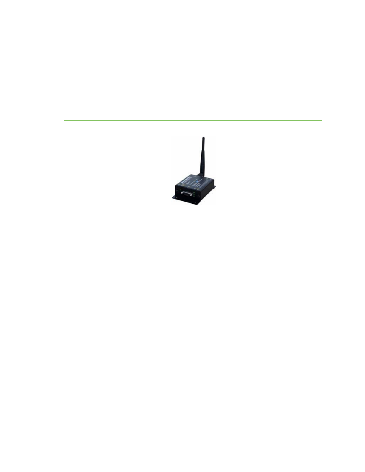
XBee-PRO USB modem
The XBee-PRO RS-232 RF modem is an IEEE 802.15.4 compliant solution that features an RS-232
interface. Out-of-box, the modem is equipped to sustain outstanding range (2-3x the range of typical
802.15.4 solutions) and requires no additional configuration for immediate RF communications. Simply
feed data into one modem, then the data is sent out the other end of the wireless link.
The modem transfers a standard asynchronous serial data stream between two or more devices. Its
built-in RS-232 interface allows for rapid integration into existing data systems.
Features overview
Long-range data integrity
Range
n Indoor/Urban: up to 300; (100 m)
n Outdoor line-of-sight: up to one mile (1.6 km)
1. Transmit power: 60 mW (18 dBm), 100 mW (w0 dBm)
Receiver sensitivity: -100 dBM
RF Data rate: 250,000 bps
Advanced networking & security
n Retries and acknowledgements
n DSSS (Direct Sequence Spread Spectrum)
n Each direct sequence channels has over 65,000 unique network addresses available
n Source/destination addressing
XBee-PRO PKG-U® USB RF Modem
6
Page 7
XBee-PRO USB modem Features overview
n Unicast and broadcast communications
n Point-to-point, point-to-multipoint and peer-to-peer topologies supported
n Coordinator/end device operations
n Transparent and API operations
n 128-bit encryption
Low power
Power currents
n Receive current: 90 mA (@9V)
n Transmit current: 300 mA
n Power-down current: < 25 mA
Easy-to-use
n No configuration necessary for out-of box RF communications.
n Free X-CTU software.
n (Testing and configuration software) built-in RS-232 interfacing.
n Small form factor.
n Network compatible with other 802.15.4 devices.
n AT and API command modes for configuring modem parameters.
Free and unlimited technical support.
Worldwide acceptance
n FCC approved (USA) refer to Appendix A [p56] for FCC requirements.
n Systems that include XBee®/XBee-PRO® RF modules inherit Digi certifications.
n ISM (industrial, scientific & medical) 2.4 GHz frequency band
n Manufactured under ISO 9001:2000 registered standards
XBee®/XBee-PRO® RF modules are optimized for use in the United States, Canada, Australia, Japan
and Europe.
Visit www.digi.com for complete list of government agency approvals.
XBee-PRO PKG-U® USB RF Modem
7
Page 8

XBee-PRO USB modem Specifications
Specifications
Specifications of the XBee-PRO RS-232 RF modem
Specification XBee-PRO
Performance
Indoor/urban range (w/2.1 dB dipole antenna) Up to 300’ (100 m)
Outdoor/urban range (w/2.1 dB dipole antenna) Up to 4000 ft (1200 m)
Transmit power output 60 mW, 100 mW (20 dBm)
1
EIRP
RF data rate 250,000 bps
Interface data rate 1200 bps - 115200 bps
(non-standard baud rates
also supported
Receiver sensitivity -100 dBm (1% packet
error rate)
Networking and security
Operating frequency ISM 2.4 GHz
Modulation DSSS (direct sequence
spread spectrum)
Supported network topologies Point-to-point, point-to-
multipoint, peer-to-peer
and mesh
Number of channels (software selectable) 12 direct sequence
channels
Addressing layers PAN ID, channel and
source/destination
addresses
Antenna
Connector RPSMA (reverse polarity
SMA)
Impedance 50 ohms unbalanced
Power requirements
Power supply Powered through USB
port
Receive current 90 mA
1
See Appendix A: agency certifications for region‐specific certification requirements.
XBee-PRO PKG-U® USB RF Modem
8
Page 9

XBee-PRO USB modem Specifications
Specification XBee-PRO
Transmit current 300 mA (Average current
when streaming data
(@9600bps) = 92 mA)
Power-down current < 25 mA
Physical properties
Size 4.500” x 2.750” x 1.125”
(11.4cm x 7.0cm x 2.9cm)
Weight 5.25 oz. (150 g)
Data connection USB
Operating temperature 0 - 70º C (commercial)
Certifications (partial list)
United States (FCC Part 15.247) OUR-XBEEPRO
Industry Canada (IC) 4214A-XBEEPRO
Europe (CE) ETSI (Max. 10 mW
transmit power output)*
XBee-PRO PKG-U® USB RF Modem
9
Page 10
XBee-PRO USB modem External interface
External interface
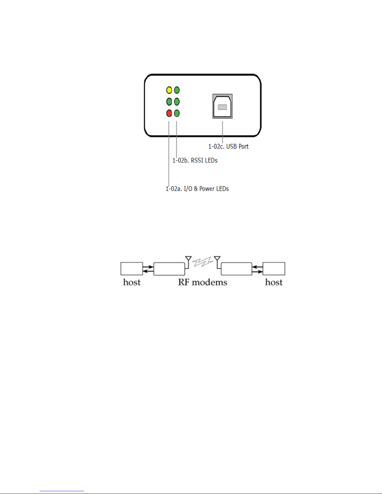
Front view
I/O & power LEDs
LEDs indicate RF modem activity as follows:
n Yellow (top LED) = serial data out (to host).
n Green (middle) = serial data In (from host).
n Red (bottom) = Power/association Indicator (refer to D5 (DIO5 Configuration) command).
RSSI LEDs
RSSI LEDs indicate the amount of fade margin present in an active wireless link. Fade margin is
defined as the difference between the incoming signal strength and the modem's receiver sensitivity.
n 3 LEDs ON = very strong signal (> 30 dB fade margin)
n 2 LEDs ON = strong signal (> 20 dB fade margin)
n 1 LED ON = moderate signal (> 10 dB fade margin)
n 0 LED ON = weak Signal (< 10 dB fade margin)
XBee-PRO PKG-U® USB RF Modem
10
Page 11
XBee-PRO USB modem External interface
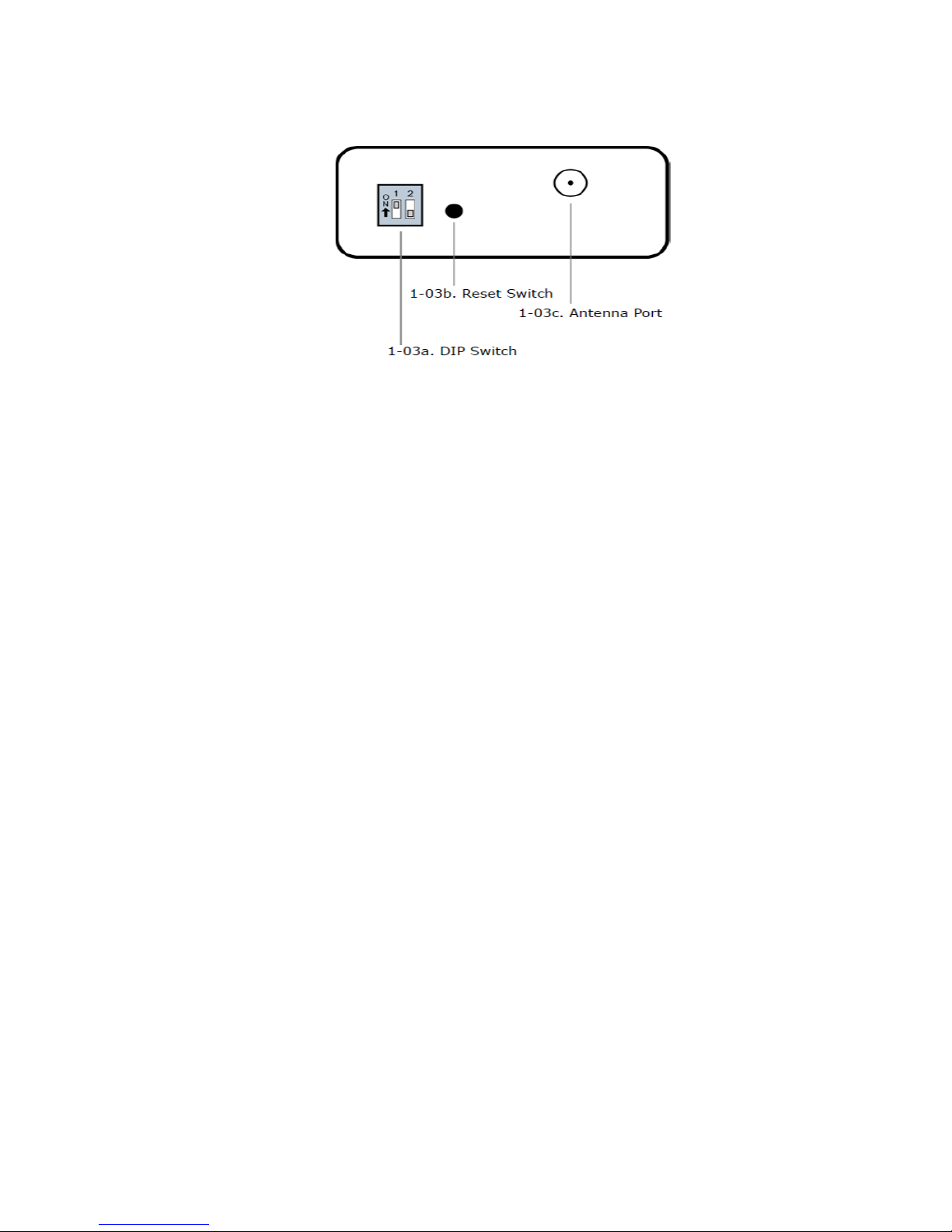
Back view
USB port
Standard type-B USB connector is used to communicate with USBhost and power the RF modem.
DIP switch
DIP switch functions are not supported in this release. Future down- loadable firmware versions will
support DIP switch configurations.
Reset swiitch
The Reset Switch is used to reset (re-boot) the RF modem.
Antenna port
Port is a 50Ω RF signal connector for connecting to an external antenna. The connector type is RPSMA
(reverse polarity SMA) female. The connector has threads on the outside of a barrel and a male center
conductor.
XBee-PRO PKG-U® USB RF Modem
11
Page 12
Interfacing protocol
RS-232 operation
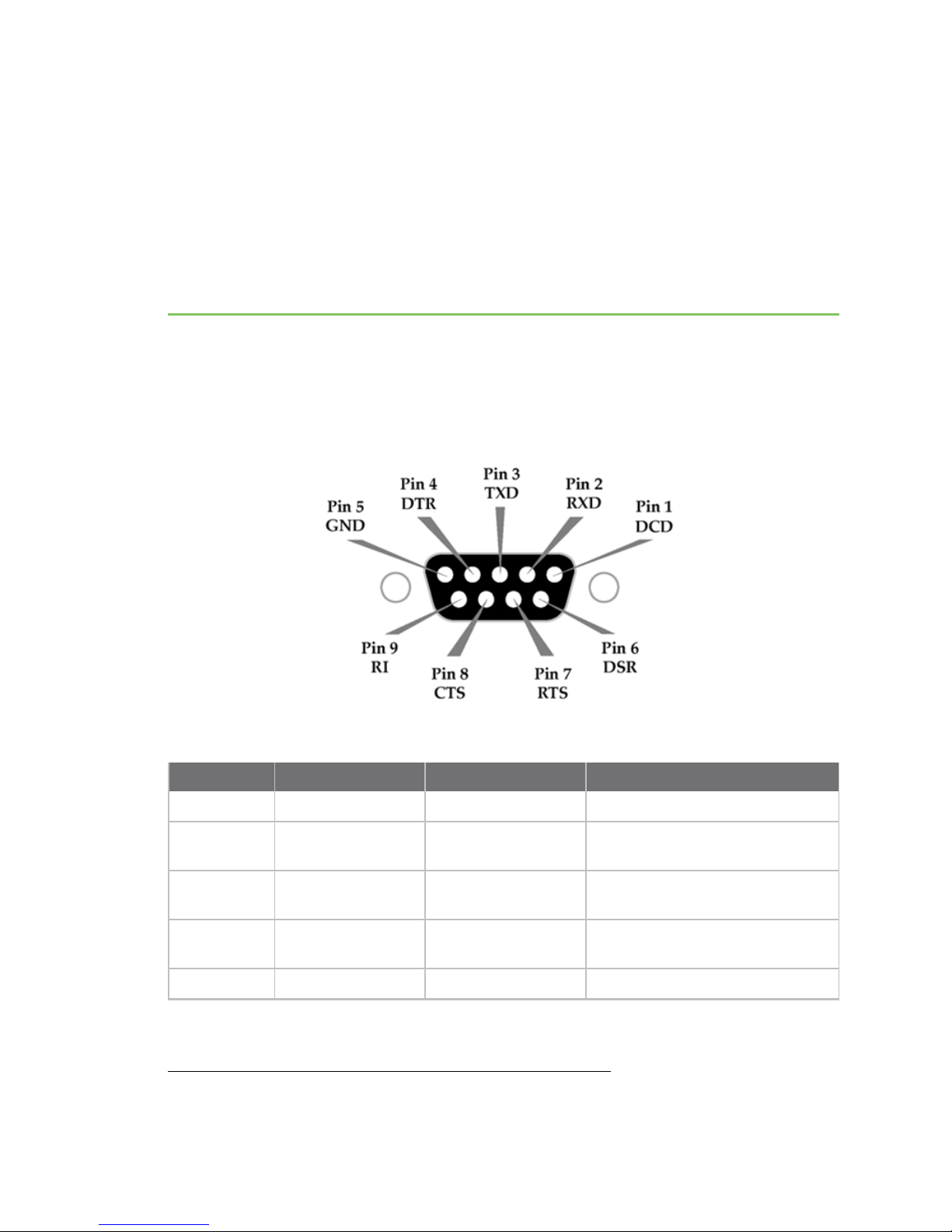
Pin signals
Pins used on the female RS-232 (DB-9) serial connector
DB-9 pin RS-232 name Description Implementation
1 DCD Data-carrier-detect Connected to DSR (pin6)
2 RXD Received data Serial data exiting the RF modem
3 TXD Transmitted data Serial data entering into the RF
4 DTR Data-terminal-ready Can enable power-down on the RF
5 GND Ground signal Ground
1
1Functions listed in the implementation column may not be available at the time of release.
XBee-PRO PKG-U® USB RF Modem
Pin assignments and implementations
1
(to host)
modem (from host)
modem
12
Page 13
Interfacing protocol RS-232 operation
DB-9 pin RS-232 name Description Implementation
6 DSR Data-set-ready Connected to DCD (pin1)
7 RTS / CMD Request-to-
send/command mode
8 CTS Clear-to-send Provides CTS flow control
9 RI Ring indicator Optional power input that is
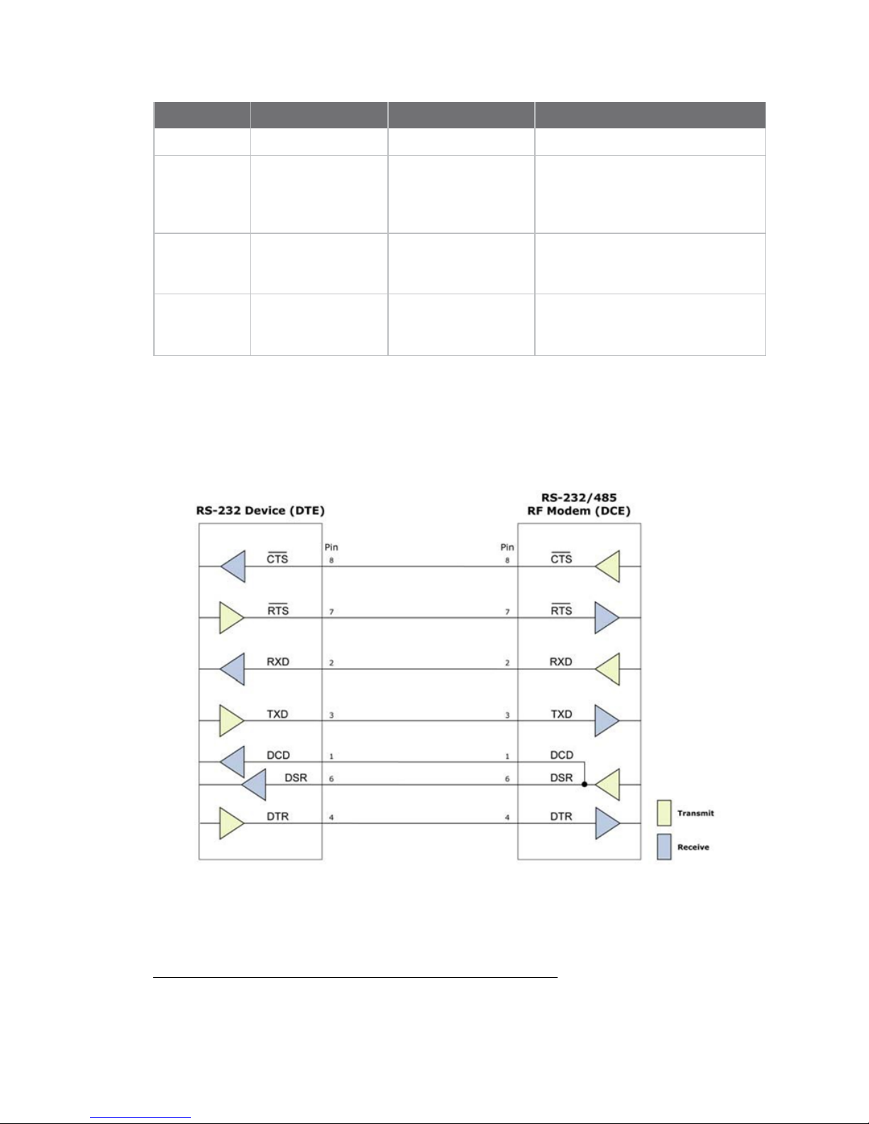
Wiring Diagrams
DTE RS-232 Device to a DCE RF Modem
RS-232 device (DTE-male connector) wired to an XBeee-PRO RF modem (DCE-female)
1
Provides RTS flow control or enables
"command mode" on the RF modem
Refer to Flow control and the D6
(DIO6 Configuration) command.
Refer to Flow control and D7 (DIO7
Configuration) command.
connected internally to the positive
lead of the front power connector
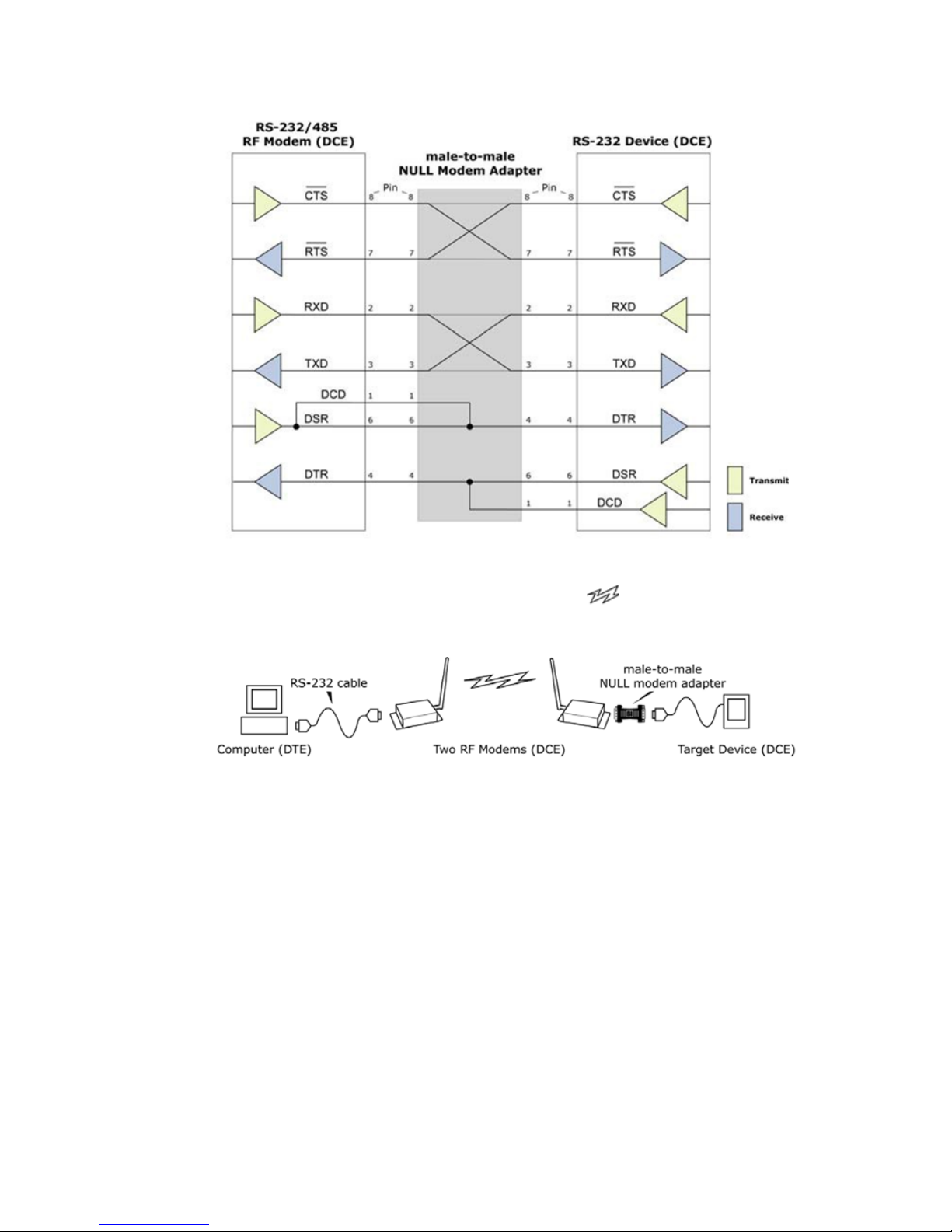
DCE RF Modem to an DCE RS-232 Device
XBee‐PRO RF modem (DCE ‐female connector) wired to an RS‐232 device (DCE)
1
1Functions listed in the implementation column may not be available at the time of release.
XBee-PRO PKG-U® USB RF Modem
13
Page 14
Interfacing protocol RS-232 operation
Sample wireless connection: DTE <--> DCE DCE <--> DCE
Typical wireless link between DTE and DCE devices
XBee-PRO PKG-U® USB RF Modem
14
Page 15
RF modem operation
Serial Communications
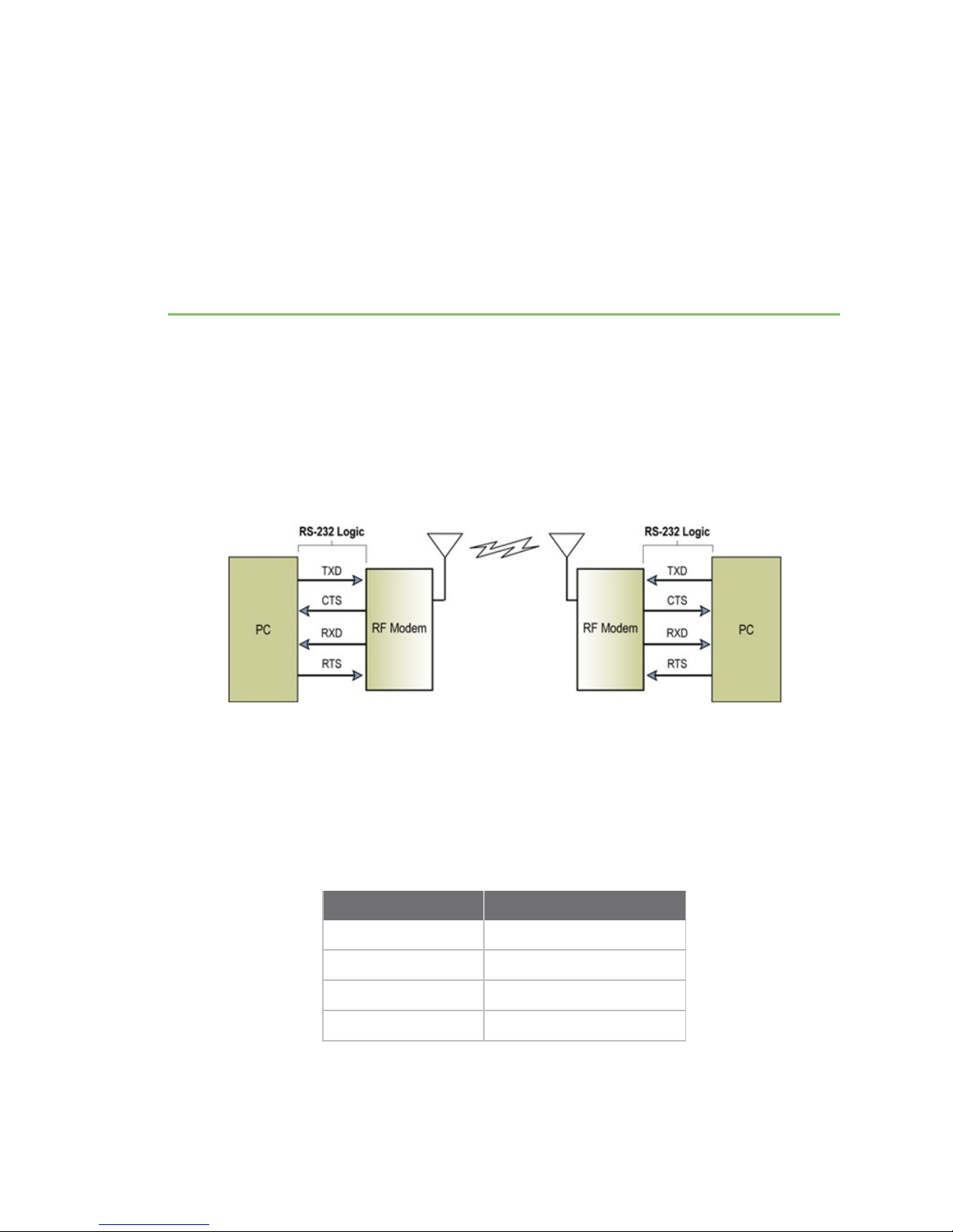
RS-232 data flow
The XBee-PRO RS-232 RF modem interfaces to a host device through a standard RS-232 (DB-9)
connector. Devices that have a standard RS-232 serial port can connect directly through the pins of
the RF modem as shown in the following figure.
System data flow in an RS‐232 environment
Host and RF modem settings
Serial communications between a host and an XBee-PRO RF modem are dependent upon having
matching baud rate, parity, stop bit & number of data bits settings. Refer to the table below to ensure
host serial port settings match those of the XBee-PRO RF modem.
XBee-PRO PKG-U® USB RF Modem
Parameter values critical to serial communications
between the RF modem and host
Parameter setting Default parameter value
Baud (serial data rate) 9600 bps (BD parameter = 3)
Number of data bits 8
Parity None
Number of stop bits 1
15
Page 16

RF modem operation Serial Communications
Both the XBee-PRO RF modem and host (PC) settings can be viewed and adjusted using Digi's
proprietary X-CTU software. Use the PC settings tab to configure host settings. Use the terminal or
RF modem configuration tabs to configure the RF modem settings.
Note Failure to enter AT command mode is most commonly due to baud rate mismatch. Ensure the
baud setting on the PC settings tab matches the BD (interface data rate) setting of the RF modem
(by default, BD parameter = 3, which is associated to 9600 baud).
Transparent operation
By default, XBee-PRO RF modems operate in transparent mode. When operating in this mode, the
modems act as a serial line replacement - all UART data received through the DI pin is queued up for
RF transmission. When RF data is received, the data is sent out the DO pin.
Serial-to-RF packetization
Data is buffered in the DI buffer until one of the following causes the data to be packetized and
transmitted:
1. No serial characters are received for the amount of time determined by the RO (packetization
timeout) parameter. If RO = 0, packetization begins when a character is received.
2. The maximum number of characters that will fit in an RF packet (100) is received.
3. The command mode sequence (GT + CC + GT) is received. Any character buffered in the DI
buffer before the sequence is transmitted.
If the modem cannot immediately transmit (for instance, if it is already receiving RF data), the serial
data is stored in the DI buffer. The data is packetized and sent at any RO timeout or when 100 bytes
(maximum packet size) are received.
If the DI buffer becomes full, hardware or software flow control must be implemented in order to
prevent overflow (loss of data between the host and modem).
API operation
API (application programming interface) operation is an alternative to the default transparent
operation. The frame-based API extends the level to which a host application can interact with the
networking capabilities of the modem.
When in API mode, all data entering and leaving the modem is contained in frames that define
operations or events within the modem.
Transmit data frames (received through the DI (Data In) pin) include:
n RF transmit data frame
n Command frame (equivalent to AT commands)
Receive data frames (sent out the data out) include:
n RF-received data frame
n Command response
n Event notifications such as reset, associate, disassociate, etc.
The API provides alternative means of configuring modems and routing data at the host application
layer. A host application can send data frames to the modem that contain address and payload
information instead of using command mode to modify addresses. The modem will send data frames
XBee-PRO PKG-U® USB RF Modem
16
Page 17
RF modem operation Serial Communications
to the application containing status packets; as well as source, RSSI and payload information from
received data packets.
The API operation option facilitates many operations such as the examples cited below:
n Transmitting data to multiple destinations without entering command mode.
n Receive success/failure status of each transmitted RF packet.
n Identify the source address of each received packet.
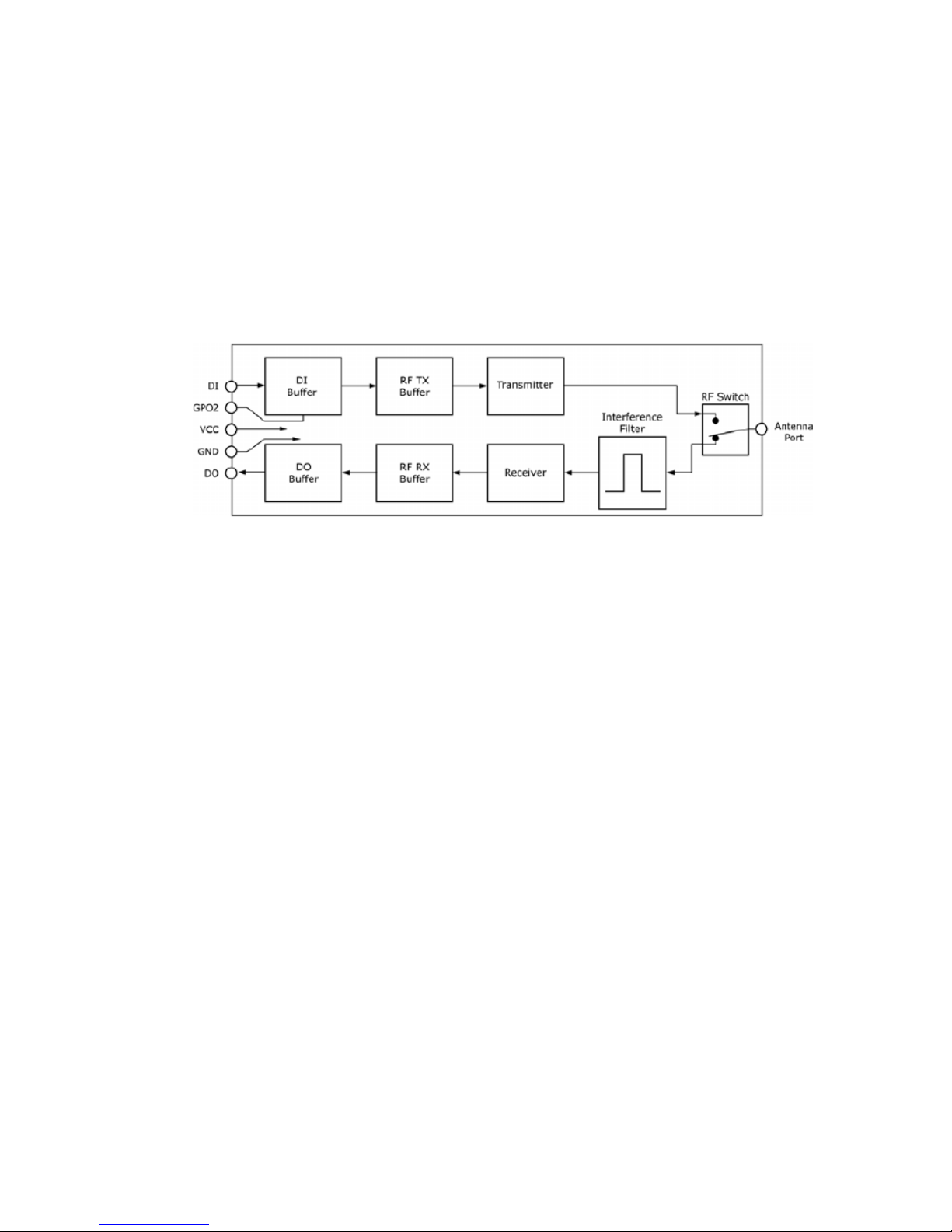
Flow control
Internal data flow diagram
DI (data In) buffer
When serial data enters the RF modem through the DI (Data In) pin, the data is stored in the DI Buffer
until it can be processed.
Hardware flow control (CTS). When the DI buffer is 17 bytes away from being full; by default, the
modem de-asserts CTS (high) to signal to the host device to stop sending data (refer to D7 (DIO7
Configuration) command. CTS is re-asserted after the DI Buffer has 34 bytes of memory available.
How to eliminate the need for flow control:
1. Send messages that are smaller than the DI buffer size.
2. Interface at a lower baud rate (BD (interface data rate) parameter] than the throughput data
rate.
Case in which the DI Buffer may become full and possibly overflow:
If the modem is receiving a continuous stream of RF data, any serial data that arrives on the DI pin is
placed in the DI Buffer. The data in the DI buffer will be transmitted over-the-air when the modem is
no longer receiving RF data in the network.
Refer to RO (Packetization Timeout) command, BD (Interface Data Rate) command, and D7 (DIO7
Configuration) command command descriptions for more information.
Refer to BD (Interface Data Rate) command and RO (Packetization Timeout) command command
descriptions for more information.
DO (data out) buffer
When RF data is received, the data enters the DO buffer and is sent out the serial port to a host
device. Once the DO buffer reaches capacity, any additional incoming RF data is lost.
Hardware flow control (RTS). If RTS is enabled for flow control (D6 (DIO6 configuration) parameter =
1), data will not be sent out the DO buffer as long as RTS (DIO6) is de-asserted.
Two cases in which the DO buffer may become full and possibly overflow:
XBee-PRO PKG-U® USB RF Modem
17
Page 18

RF modem operation Serial Communications
1. If the RF data rate is set higher than the interface data rate of the modem, the modem will
receive data from the transmitting modem faster than it can send the data to the host.
2. If the host does not allow the modem to transmit data out from the DO buffer because of being
held off by hardware or software flow control.
To implement API operations, refer to API operation.
IEEE 802.15.4 networks
The following IEEE 802.15.4 network types are available to the RF modem:
n NonBeacon
n NonBeacon (w/coordinator)
The following terms will be used to explicate the network system types:
Terms and definitions (Applicable networking network types are designated within <brackets>.)
Term Definition
Association <NonBeacon (w/coordinator) systems only>
The establishment of membership between end devices and a coordinator.
<NonBeacon (w/coordinator) systems only>
Coordinator
A central RF modem that is configured to provide synchronization services through
the transmission of beacons.
End device When in the same network as a coordinator - RF modems that rely on a coordinator
for synchronization and can be put into states of sleep for low-power applications.
PAN Personal area network - A data communication network that includes one or more
end devices and optionally a coordinator.
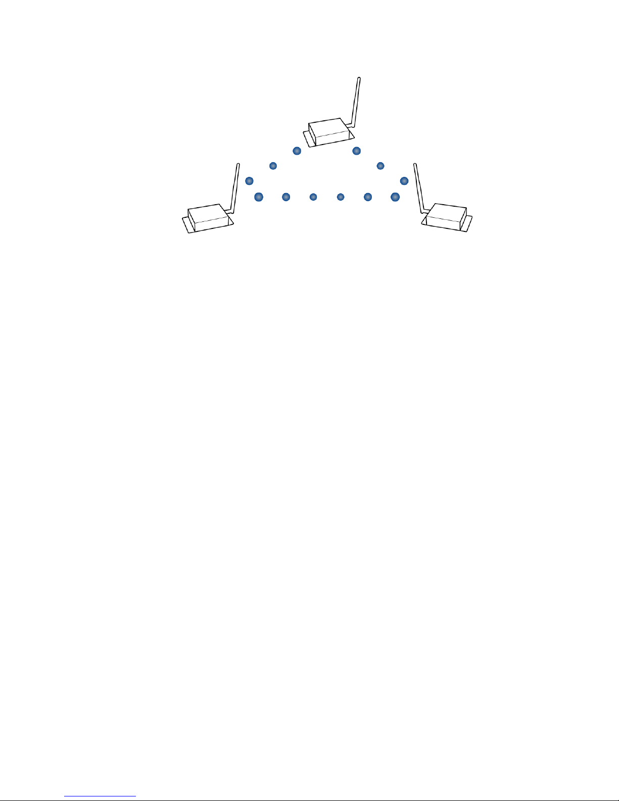
NonBeacon
By default, XBee-PRO RF modems are configured to support NonBeacon communications (no
coordinator). NonBeacon systems operate within a peer-to-peer network topology and are not
dependent upon master/slave relationships. This means that modems remain synchronized without
use of master/server configurations and each modem in the network shares both roles of master and
slave. Digi's peer-to-peer architecture features fast synchronization times and fast cold start times.
This default configuration accommodates a wide range of RF data applications.
NonBeacon peer-to-peer architecture
XBee-PRO PKG-U® USB RF Modem
18
Page 19
RF modem operation Serial Communications
A peer-to-peer network can be established by configuring each modem to operate as an end device
(CE = 0), disabling end device association on all modems (A1 = 0) and setting ID and CH parameters to
be identical across the network.
NonBeacon (with coordinator)
A device is configured as a coordinator by setting the CE (Coordinator Enable) parameter to “1”.
Coordinator power-up is governed by the A2 (Coordinator Association) command.
In a NonBeacon (w/coordinator) system, the coordinator can be configured to use direct or indirect
transmissions. If the SP (Cyclic Sleep Period) parameter is set to “0," the coordinator sends data
immediately. Otherwise, the SP parameter determines the length of time the coordinator will retain
the data before discarding it. Generally, SP (Cyclic Sleep Period) and ST (Time before Sleep)
parameters should be set to match the SP and ST settings of the end devices.
Association plays a critical role in the implementation of a NonBeacon (with coordinator) system.
Refer to Association for more information.
Association
Association is the establishment of membership between end devices and a coordinator and is only
applicable in NonBeacon (w/coordinator) networks. The establishment of membership is useful in
scenarios that require a central unit (coordinator) to relay messages to or gather data from several
remote units (end devices), assign channels or assign PAN IDs.
An RF data network that consists of one coordinator and one or more end devices forms a PAN
(personal area network). Each device in a PAN has a PAN identifier [ID (PAN ID) parameter]. PAN IDs
must be unique to prevent miscommunication between PANs. The coordinator PAN ID is set using the
ID (PAN ID) and A2 (coordinator association) commands.
An end device can associate to a coordinator without knowing the address, PAN ID or channel of the
coordinator. The A1 (End Device Association) parameter bit fields determine the flexibility of an end
device during association. The A1 parameter can be used for an end device to dynamically set its
destination address, PAN ID and/or channel.
For example: If the PAN ID of a coordinator is known, but the operating channel is not; the A1
command on the end device should be set to enable the Auto_Associate and Reassign_Channel bits.
Additionally, the ID parameter should be set to match the PAN ID of the associated coordinator.
Coordinator/end device setup and operation
To configure a modem to operate as a coordinator, set the CE (Coordinator Enable) parameter to 1.
Set the CE parameter of End Devices to 0 (default). Coordinator and end devices should contain
XBee-PRO PKG-U® USB RF Modem
19
Page 20

RF modem operation Serial Communications
matching firmware versions.
NonBeacon (w/coordinator) systems
In a NonBeacon (w/coordinator) system, the coordinator can be configured to use direct or indirect
transmissions. If the SP (Cyclic Sleep Period) parameter is set to 0,, the Coordinator will send data
immediately. Otherwise, the SP parameter determines the length of time the Coordinator will retain
the data before discarding it. Generally, SP (Cyclic Sleep Period) and ST (Time before Sleep)
parameters should be set to match the SP and ST settings of the end devices.
Coordinator Power-up
Coordinator power-up is governed by the A2 (Coordinator Association) command. On power-up, the
coordinator undergoes the following sequence of events:
1. Check A2 parameter- reassign_PANID flag
Set (bit 0 = 1) - The coordinator issues an active scan. The active scan selects one channel and
transmits a BeaconRequest command to the broadcast address (0xFFFF) and broadcast PAN
ID (0xFFFF). It then listens on that channel for beacons from any coordinator operating on that
channel. The listen time on each channel is determined by the SD (Scan Duration) parameter
value.
Once the time expires on that channel, the active scan selects another channel and again
transmits the BeaconRequest as before. This process continues until all channels have been
scanned, or until 5 PANs have been discovered. When the active scan is complete, the results
include a list of PAN IDs and channels that are being used by other PANs. This list is used to
assign an unique PAN ID to the new coordinator. The ID parameter will be retained if it is not
found in the active scan results. Otherwise, the ID (PAN ID) parameter setting will be updated
to a PAN ID that was not detected.
Not Set (bit 0 = 0) - The coordinator retains its ID setting. No active scan is performed.
2. Check A2 parameter - reassign_channel flag (bit 1)
Set (bit 1 = 1) - The coordinator issues an energy scan. The energy scan selects one channel
and scans for energy on that channel. The duration of the scan is specified by the SD (Scan
Duration) parameter. Once the scan is completed on a channel, the energy scan selects the
next channel and begins a new scan on that channel. This process continues until all channels
have been scanned.
When the energy scan is complete, the results include the maximal energy values detected on
each channel. This list is used to determine a channel where the least energy was detected. If
an active scan was performed (reassign_PANID flag set), the channels used by the detected
PANs are eliminated as possible channels. Thus, the results of the energy scan and the active
scan (if performed) are used to find the best channel (channel with the least energy that is not
used by any detected PAN). Once the best channel has been selected, the CH (Channel)
parameter value is updated to that channel.
Not set (bit 1 = 0) - The coordinator retains its CH setting. An energy scan is not performed.
XBee-PRO PKG-U® USB RF Modem
20
Page 21

RF modem operation Serial Communications
3. Start coordinator
The coordinator starts on the specified channel (CH parameter) and PAN ID (ID parameter).
Note, these may be selected in steps 1 and/or 2 above. The coordinator will only allow end
devices to associate to it if the A2 parameter “AllowAssociation” flag is set. Once the
coordinator has successfully started, the Associate LED will blink one time per second. (The LED
is solid if the coordinator has not started.)
4. Coordinator modifications
Once a coordinator has started:
Modifying the A2 (Reassign_Channel or Reassign_PANID bits), ID, CH or MY parameters will
cause the coordinator’s MAC to reset (The coordinator RF modem (including volatile RAM) is
not reset). Changing the A2 AllowAssociation bit will not reset the coordinator’s MAC. In a non-
beaconing system, end devices that are associated to the coordinator prior to a MAC reset will
have knowledge of the new settings on the Coordinator. Thus, if the Coordinator were to
change its ID, CH or MY settings, the End Devices would no longer be able to communicate with
the non-beacon coordinator. Once a coordinator has started, the ID, CH, MY or A2 (Reassign_
Channel or Reassign_PANID bits) should not be changed.
End device power-up
End device power-up is governed by the A1 (End Device Association) command. On power-up, the end
device undergoes the following sequence of events:
1. Check A1 parameter -11 AutoAssociate bit.
Set (bit 2 = 1) - End device will attempt to associate to a coordinator. (refer to steps 2-3).
Not Set (bit 2 = 0) - End device will not attempt to associate to a coordinator. The end device
will operate as specified by its ID, CH and MY parameters. Association is considered complete
and the Associate LED blinks quickly (5 times per second). When the AutoAssociate bit is not
set, the remaining steps (2-3) do not apply.
XBee-PRO PKG-U® USB RF Modem
21
Page 22

RF modem operation Serial Communications
2. Discover coordinator (if AutoAssociate bit set).
The end device issues an active scan. The active scan selects one channel and transmits a
BeaconRequest command to the broadcast address (0xFFFF) and broadcast PAN ID (0xFFFF).
It then listens on that channel for beacons from any coordinator operating on that channel. The
listen time on each channel is determined by the SD parameter.
Once the time expires on that channel, the active scan selects another channel and again
transmits the BeaconRequest command as before. This process continues until all channels
have been scanned, or until 5 PANs have been discovered. When the active scan is complete,
the results include a list of PAN IDs and channels that are being used by detected PANs.
The end device selects a coordinator to associate with according to the A1 parameter
(Reassign_PANID) and (Reassign_Channel) flags:
Reassign_PANID Bit Set (bit 0 = 1)- end device can associate with a PAN with any ID value.
Reassign_PANID Bit Not Set (bit 0 = 0) - end device will only associate with a PAN whose ID
setting matches the ID setting of the end device.
Reassign_Channel bit set (bit 1 = 1) - end device can associate with a PAN with any CH
value.
Reassign_Channel bit not set (bit 1 = 0)- end device will only associate with a PAN whose
CH setting matches the CH setting of the end device.
After applying these filters to the discovered coordinators, if multiple candidate PANs exist, the
end device will select the PAN whose transmission link quality is the strongest. If no valid
coordinator is found, the end device will either go to sleep (as dictated by its SM (Sleep Mode)
parameter) or retry association.
Note An end device will also disqualify coordinators if they are not allowing association (A2 -
AllowAssociation bit); or, if the coordinator is not using the same NonBeacon scheme as the
end device. (They must both be programmed with NonBeacon code.)
3. Associate to valid coordinator.
Once a valid coordinator is found (step 2), the End Device sends an AssociationRequest
message to the coordinator. It then waits for an AssociationConfirmation to be sent from the
coordinator. Once the confirmation is received, the end device is associated and the Associate
LED blinks rapidly (2 times per second). The LED is solid if the end device has not associated.
4. End device changes once an end device has associated.
Changing A1, ID or CH parameters will cause the end device to disassociate and restart the
association procedure.
If the end device fails to associate, the AI command can give some indication of the failure.
XBee-PRO PKG-U® USB RF Modem
22
Page 23

RF modem operation Serial Communications
Addressing
Every RF data packet sent over-the-air contains a source address and destination address field in its
header. The RF modem conforms to the 802.15.4 specification and supports both short 16-bit
addresses and long 64-bit addresses. A unique 64-bit IEEE source address is assigned at the factory
and can be read with the SL (Serial Number Low) and SH (Serial Number High) commands. Short
addressing must be configured manually. A modem will use its unique 64-bit address as its source
address if its MY (16-bit Source Address) value is 0xFFFF or 0xFFFE.
To send a packet to a specific modem using 64-bit addressing: set destination address (DL + DH) to
match the source address (SL + SH) of the intended destination modem.
To send a packet to a specific modem using 16-bit addressing: Set DL (Destination Address Low)
parameter to equal the MY parameter and set the DH (Destination Address High) parameter to 0.
Unicast mode
By default, the RF modem operates in Unicast node. Unicast mode is the only mode that supports
retries. While in this mode, receiving modems send an ACK (acknowledgement) of RF packet reception
to the transmitter. If the transmitting modem does not receive the ACK, it will re-send the packet up
to three times or until the ACK is received.
Short 16-bit addresses
The modem can be configured to use short 16-bit addresses as the source address by setting (MY <
0xFFFE). Setting the DH parameter (DH = 0) will configure the destination address to be a short 16-bit
address (if DL < 0xFFFE). For two modems to communicate using short addressing, the destination
address of the transmitter modem must match the MY parameter of the receiver.
The following table shows a sample network configuration that would enable Unicast mode
communications using short 16-bit addresses.
Sample Unicast network configuration
(using 16‐bit addressing)
Parameter RF modem 1 RF modem 2
MY (Source Address) 0x01 0x02
DH (Destination Address High) 0 0
DL (Destination Address Low) 0x02 0x01
Long 64-bit addresses
The RF modem’s serial number (SL parameter concatenated to the SH parameter) can be used as a
64-bit source address when the MY (16-bit Source Address) parameter is disabled. When the MY
parameter is disabled (set MY = 0xFFFF or 0xFFFE), the modem’s source address is set to the 64-bit
IEEE address stored in the SH and SL parameters.
When an end device associates to a coordinator, its MY parameter is set to 0xFFFE to enable 64- bit
addressing. The 64-bit address of the modem is stored as SH and SL parameters. To send a packet to
a specific modem, the destination address (DL + DH) on one modem must match the source address
(SL + SH) of the other.
Broadcast mode
Any RF modem within range will accept a packet that contains a broadcast address. When configured
to operate in Broadcast mode, receiving modems do not send ACKs (acknowledgements) and
transmitting modems do not automatically re-send packets as is the case in Unicast mode.
XBee-PRO PKG-U® USB RF Modem
23
Page 24
RF modem operation Serial Communications
To send a broadcast packet to all modems regardless of 16-bit or 64-bit addressing, set the
destination addresses of all the modems as shown below.
Sample network configuration (All modems in the network):
n DL (Destination Low Address) = 0x0000FFFF
n DH (Destination High Address) = 0x00000000 (default value)
Note When programming the modem, parameters are entered in hexadecimal notation (without the
“0x” prefix). Leading zeros may be omitted.
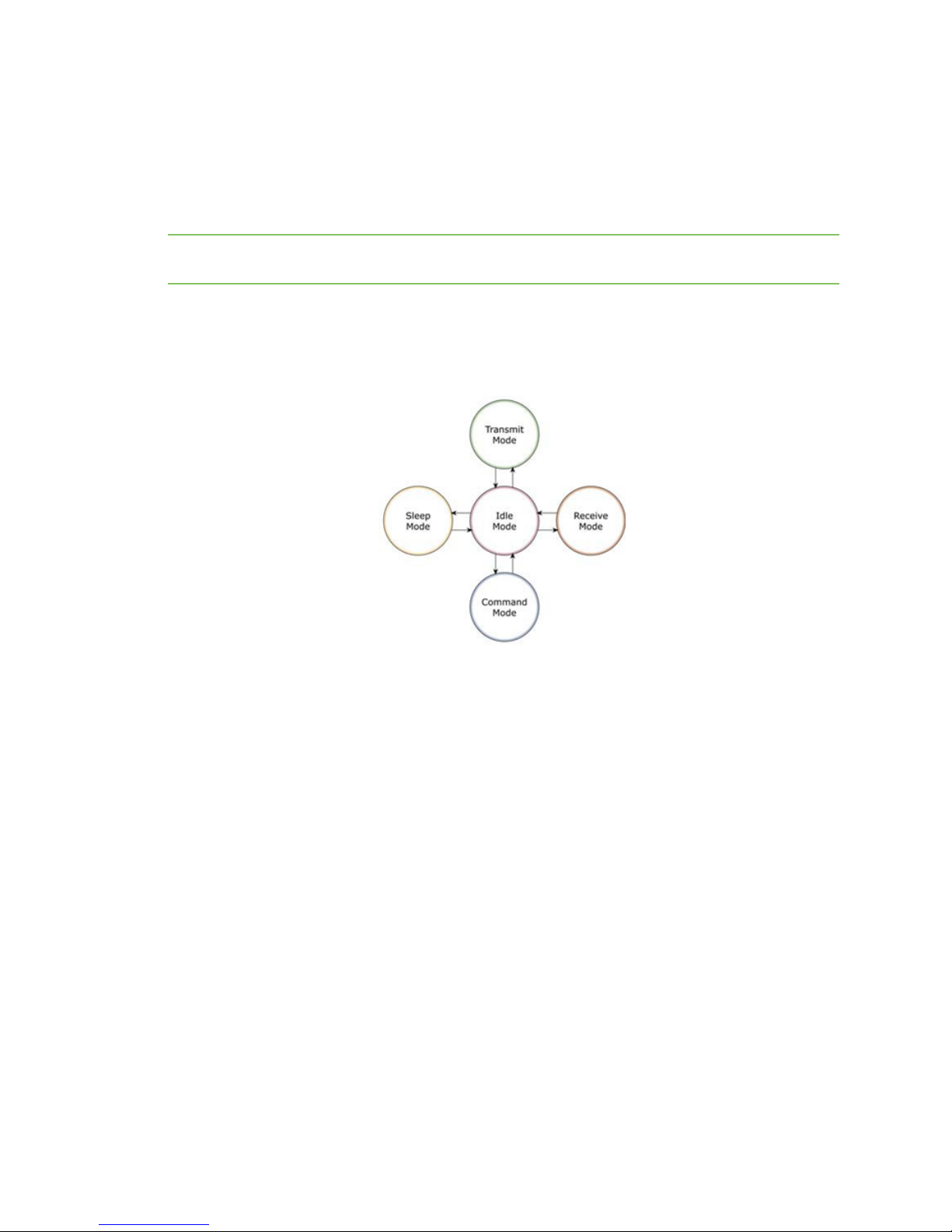
Modes of operation
XBee-PRO RF modems operate in five modes.
Modes of operation
Idle mode
When not receiving or transmitting data, the RF modem is in idle mode. The modem shifts into the
other modes of operation under the following conditions:
n Transmit mode (serial data is received in the DI buffer).
n Receive mode (valid RF data is received through the antenna).
n Sleep mode (sleep mode condition is met).
n Command mode (command mode sequence is issued).
Transmit/receive modes
RF data packets
Each transmitted data packet contains a source address and destination address field. The source
address matches the address of the transmitting modem as specified by the MY (Source Address)
parameter (if MY >= 0xFFFE), the SH (Serial Number High) parameter or the SL (Serial Number Low)
parameter. The <Destination Address> field is created from the DH (Destination Address High) and DL
(Destination Address Low) parameter values. The source address and/or destination address fields
will either contain a 16-bit short or long 64-bit long address.
The RF data packet structure follows the 802.15.4 specification.
XBee-PRO PKG-U® USB RF Modem
24
Page 25

RF modem operation Serial Communications
Refer to Addressing for more information.
Direct and indirect transmission
There are two methods to transmit data:
n Direct transmission - data is transmitted immediately to the destination address.
n Indirect transmission - A packet is retained for a period of time and is only transmitted after
the destination modem (source address = destination address) requests the data.
Indirect transmissions can only occur on a coordinator. Thus, if all nodes in a network are end devices,
only direct transmissions will occur. Indirect transmissions are useful to ensure packet delivery to a
sleeping node. The coordinator currently is able to retain up to two indirect messages.
Direct transmission
A NonBeaconing coordinator can be configured to use only direct transmission by setting the SP
(Cyclic Sleep Period) parameter to 0. Also, a NonBeaconing coordinator using indirect transmissions
will revert to direct transmission if it knows the destination modem is awake.
To enable this behavior, the ST (Time before Sleep) value of the coordinator must be set to match the
ST value of the end device. Once the end device either transmits data to the coordinator or polls the
coordinator for data, the coordinator uses direct transmission for all subsequent data transmissions
to that modem address until ST time (or number of beacons) occurs with no activity (at which point it
will revert to using indirect transmissions for that modem address). No activity means no
transmission or reception of messages with a specific address. Global messages will not reset the ST
timer.
Indirect transmission
To configure indirect transmissions in a PAN (personal area network), the SP (Cyclic Sleep Period)
parameter value on the coordinator must be set to match the longest sleep value of any end device.
The SP parameter represents time in NonBeacon systems and beacons in Beacon-enabled systems.
The sleep period value on the coordinator determines how long (time or number of beacons) the
coordinator will retain an indirect message before discarding it.
In NonBeacon networks, an end device must poll the coordinator once it wakes from sleep to
determine if the coordinator has an indirect message for it. For cyclic sleep modes, this is done
automatically every time the modem wakes (after SP time). For pin sleep modes, the A1 (End Device
Association) parameter value must be set to enable coordinator polling on pin wake-up. Alternatively,
an end device can use the FP (Force Poll) command to poll the coordinator as needed.
CCA (clear channel assessment)
Prior to transmitting a packet, a CCA (clear channel assessment) is performed on the channel to
determine if the channel is available for transmission. The detected energy on the channel is
compared with the CA (Clear Channel Assessment) parameter value. If the detected energy exceeds
the CA parameter value, the packet is not transmitted.
Also, a delay is inserted before a transmission takes place. This delay is settable using the RN (Backoff
Exponent) parameter. If RN is set to “0”, then there is no delay before the first CCA is performed. The
RN parameter value is the equivalent of the “minBE” parameter in the 802.15.4 specification. The
transmit sequence follows the 802.15.4 specification.
XBee-PRO PKG-U® USB RF Modem
25
Page 26

RF modem operation Serial Communications
By default, the MM (MAC Mode) parameter = 0. On a CCA failure, the modem will attempt to re- send
the packet up to two additional times.
When in Unicast packets with RR (Retries) = 0, the modem will execute two CCA retries. Broadcast
packets always get two CCA retries.
Acknowledgment
If the transmission is not a broadcast message, the modem will expect to receive an acknowledgment
from the destination node. If an acknowledgment is not received, the packet will be resent up to 3
more times. If the acknowledgment is not received after all transmissions, an ACK failure is recorded.
Sleep mode
Sleep modes enable the RF modem to enter states of low-power consumption when not in use. In
order to enter sleep mode, one of the following conditions must be met (in addition to the modem
having a non-zero SM parameter value):
n DTR (data terminal ready) is de-asserted.
n The modem is idle (no data transmission or reception) for the amount of time defined by the ST
(Time before Sleep) parameter. Note ST is only active when SM = 4-5.
Transition
into sleep
Sleep mode setting
Pin hibernate (SM =1)De-assert
Pin Doze (SM = 2) De-assert
Cyclic Sleep (SM = 4 -
5)
mode
DTR (data
terminal
ready)
DTR (data
terminal
ready)
Automatic
transition to
sleep mode
as defined by
the SM
(Sleep Mode)
and ST (Time
before
Sleep)
parameters.
Sleep mode configurations
Transition
out of sleep
mode (wake)
Assert DTR Pin/host-
Assert DTR Pin/host-
Transition
occurs after
the cyclic
sleep time
interval
elapses. The
time interval is
defined by the
SP (Cyclic
Sleep Period)
parameter.
Characteristics
controlled /
NonBeacon
systems only /
lowest power
controlled /
NonBeacon
systems only /
fastest wakeup
RF modem
wakes in predetermined
time intervals
to detect if RF
data is present
/ When SM = 5,
NonBeacon
systems only
Related
commands
(SM) < 6 mA
(SM) < 6 mA
(SM), SP,ST< 25 mA
Power
consumption
when
sleeping
XBee-PRO PKG-U® USB RF Modem
26
Page 27

RF modem operation Serial Communications
The SM command is central to setting sleep mode configurations. By default, sleep modes are
disabled (SM = 0) and the modem remains in idle/receive mode. When in this state, the modem is
constantly ready to respond to serial or RF activity.
Higher voltages
Sleep mode current consumption is highly sensitive to voltage. Voltages above 3.0V will cause much
higher current consumption.
Sample sleep mode currents
XBee
XBee-PRO
Vcc (V) SM=1 SM=2 SM=4,5 SM=1 SM=2 SM=4,5
2.8–3.0 <3 µA <35uA <34uA <4uA <34uA <34uA
3.1 8uA 37mA 36uA 12uA 39uA 37uA
3.2 32uA 48uA 49uA 45uA 60uA 55uA
3.3 101uA 83uA 100uA 130uA 115uA 120uA
3.4 255uA 170uA 240uA 310uA 260uA 290uA
Pin/Host-controlled sleep modes
The transient current when waking from pin sleep (SM = 1 or 2) does not exceed the idle current of the
modem. The current ramps up exponentially to its idle current.
Pin hibernate (SM = 1)
n Pin/host-controlled
n Typical power-down current: < 6 mA
n Typical wake-up time: 10.2 msec
Pin hibernate mode minimizes quiescent power (power consumed when in a state of rest or
inactivity). This mode is voltage level-activated; when DTR is de-asserted, the modem will finish any
transmit, receive or association activities, enter idle mode and then enter a state of sleep. The
modem will not respond to either serial or RF activity while in pin sleep.
To wake a sleeping modem operating in Pin Hibernate mode, assert DTR (data terminal ready). The
modem will wake when DTR is asserted and is ready to transmit or receive when the CTS line is low.
When waking the modem, the pin must be asserted at least two 'byte times' after CTS goes low. This
assures that there is time for the data to enter the DI buffer.
Pin doze (SM = 2)
n Pin/host-controlled
n Typical power-down current: < 6 mA
n Typical wake-up time: 2.6 msec
Pin doze mode functions like does Pin Hibernate Mode; however, Pin Doze features faster wake-up
time and higher power consumption.
To wake a sleeping modem operating in Pin Doze Mode, assert DTR (data terminal ready). The modem
will wake when DTR is asserted and is ready to transmit or receive when the CTS line is low. When
waking the modem, the pin must be asserted at least two 'byte times' after CTS goes low. This
assures that there is time for the data to enter the DI buffer.
XBee-PRO PKG-U® USB RF Modem
27
Page 28

RF modem operation Serial Communications
Cyclic sleep modes
Cyclic sleep remote (SM = 4)
n Typical power-down current: < 25 mA (when asleep)
n Typical wake-up time: 2.6 msec
The cyclic sleep modes allow modems to periodically check for RF data. When the SM parameter is set
to ‘4’, the modem is configured to sleep, then wakes once a cycle to check for data from a modem
configured as a cyclic sleep coordinator (SM = 0, CE = 1). The cyclic sleep remote sends a poll request
to the coordinator at a specific interval set by the SP (Cyclic Sleep Period) parameter. The coordinator
will transmit any queued data addressed to that specific remote upon receiving the poll request.
If no data is queued for the remote, the coordinator will not transmit and the remote will return to
sleep for another cycle. If queued data is transmitted back to the remote, it will stay awake to allow
for back and forth communication until the ST (Time before Sleep) timer expires.
Also note that CTS will go low each time the remote wakes, allowing for communication initiated by
the remote host if desired.
Cyclic sleep remote with pin wake-up (SM = 5)
Use this mode to wake a sleeping remote modem through either the RF interface or by the assertion
of DTR for event-driven communications. The cyclic sleep mode works as described above (cyclic sleep
remote) with the addition of a pin-controlled wake-up at the remote modem. The DTR pin is edgetriggered, not level-triggered. The modem will wake when a low is detected then set CTS low as soon
as it is ready to transmit or receive.
Any activity will reset the ST (Time before Sleep) timer so the modem will go back to sleep only after
there is no activity for the duration of the timer. Once the module wakes (pin-controlled), further pin
activity is ignored. The modem transitions back into sleep according to the ST time regardless of the
state of the pin.
[Cyclic sleep coordinator (SM = 6)]
n Typical current = receive current
n Always awake
Note The SM=6 parameter value exists solely for backwards compatibility with firmware version
1.x60. If backwards compatibility with the older firmware version is not required, always use the CE
(Coordinator Enable) command to configure a modem as a coordinator.
This mode configures a modem to wake cyclic sleeping remotes through RF interfacing. The
coordinator will accept a message addressed to a specific remote 16 or 64-bit address and hold it in a
buffer until the remote wakes and sends a poll request. Messages not sent directly (buffered and
requested) are called indirect messages. The coordinator only queues one indirect message at a time.
The coordinator will hold the indirect message for a period 2.5 times the sleeping period indicated by
the SP (Cyclic Sleep Period) parameter. The coordinator's SP parameter should be set to match the
value used by the remotes.
Command mode
To modify or read RF modem parameters, the modem must first enter into Command mode - a state
in which incoming characters are interpreted as commands. Two command mode types are
supported: AT command mode and API command mode.
AT command mode
To enter AT command mode:
XBee-PRO PKG-U® USB RF Modem
28
Page 29
RF modem operation Serial Communications
Send the 3-character command sequence “+++” and observe guard times before and after the
command characters.
Default AT Command Mode Sequence (for transition to Command mode):
n No characters sent for one second GT (Guard Times) parameter = 0x3E8.
n Input three plus characters (“+++”) within one second [CC (Command Sequence Character)
parameter = 0x2B.
n No characters sent for one second GT (Guard Times) parameter = 0x3E8.
All of the parameter values in the sequence can be modified to reflect user preferences.
Note Failure to enter AT Command mode is most commonly due to baud rate mismatch. Ensure the
baud setting on the PC Settings tab matches the interface data rate of the RF modem. By default,
the BD parameter = 3 (9600 bps).
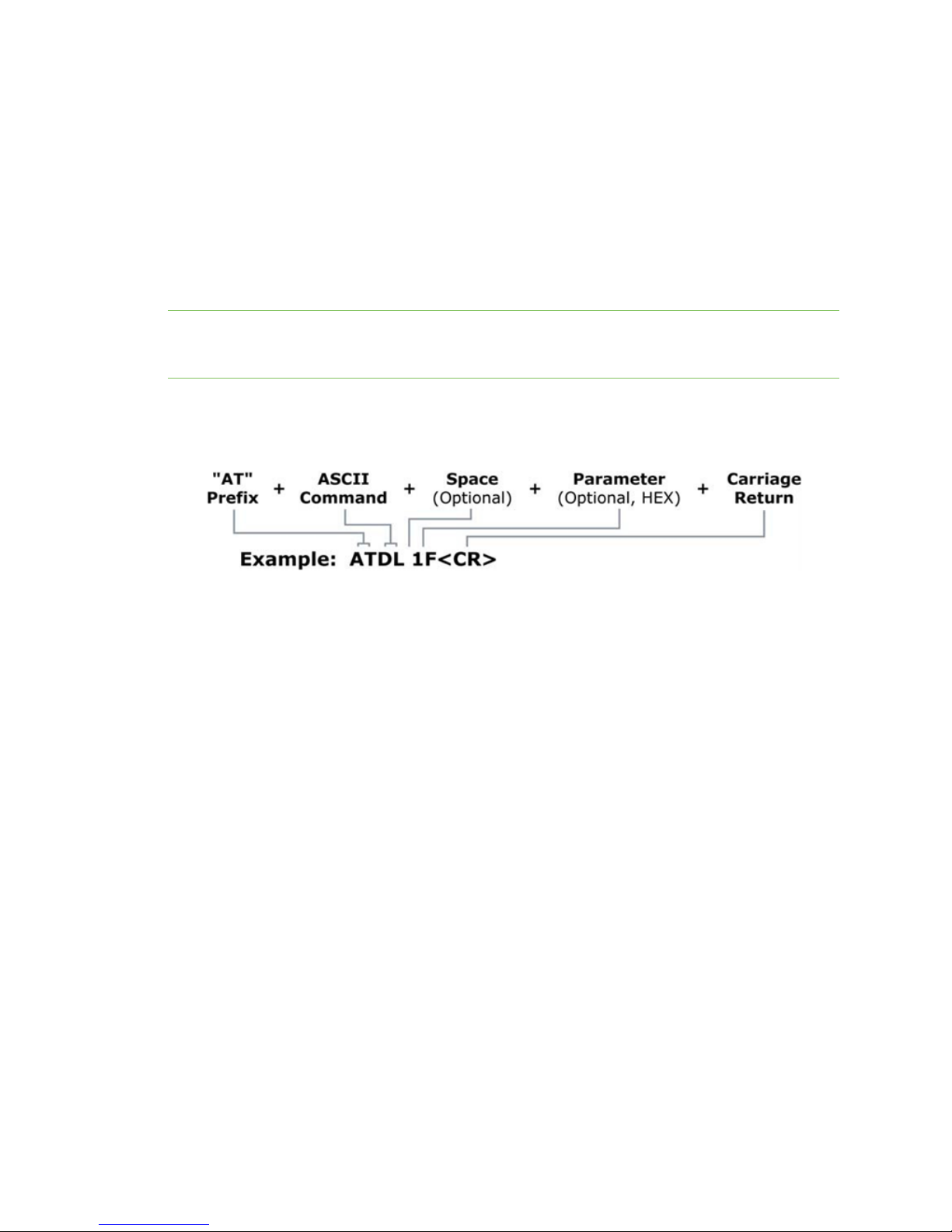
To send AT commands:
Send AT commands and parameters using the syntax shown below.
Syntax for sending AT commands
To read a parameter value stored in the RF modem’s register, omit the parameter field.
The preceding example would change the RF modem destination address (Low) to “0x1F”. To store
the new value to non-volatile (long term) memory, subsequently send the WR (Write) command.
For modified parameter values to persist in the modem’s registry after a reset, changes must be
saved to non-volatile memory using the WR (Write) command. Otherwise, parameters are restored to
previously saved values after the modem is reset.
System response
When a command is sent to the modem, the modem will parse and execute the command. Upon
successful execution of a command, the modem returns an “OK” message. If execution of a command
results in an error, the modem returns an “ERROR” message.
To exit AT Command mode:
1. Send the ATCN (Exit Command Mode) command (followed by a carriage return).
OR
2. If no valid AT commands are received within the time specified by CT (Command Mode
Timeout) Command, the RF modem automatically returns to Idle Mode.
For an example that illustrates programming the RF modem using AT commands, refer to RF modem
configuration.
XBee-PRO PKG-U® USB RF Modem
29
Page 30

RF modem configuration
Programming the RF Modem
Refer to the Command mode section for more information about entering Command Mode, sending
AT commands and exiting Command Mode. For information regarding modem programming using API
Mode, refer to the API operation.
Programming Examples
Setup
The programming examples in this section require the installation of Digi's X-CTU software and an RS232 connection to a PC.
1. Install Digi's X-CTU software to a PC by double-clicking the "setup_X-CTU.exe" file. (The file is
located on the Digi CD and under the Software section of the following web page:
www.maxstream.net/support/downloads.php. Refer to the the X-CTU software section for
more information.
2. Connect the RF modem to a PC using their respective serial ports.
3. Launch the X-CTU software and select the PC Settings tab. Verify the baud and parity settings
of the Com port match those of the RF modem.
Note Failure to enter AT Command mode is most commonly due to baud rate mismatch. Ensure the
baud setting on the PC Settings tab matches the interface data rate of the RF modem (by default, BD
parameter = 3 (which corresponds to 9600 bps)).
Sample configuration: modify RF modem destination address
Example: Utilize the X-CTU Terminal tab to change the RF modem's DL (Destination Address Low)
parameter and save the new address to non-volatile memory.
After establishing a serial connection between the RF modem and a PC refer to the Setup section
above, select the Terminal tab of the X-CTU software and enter the following command lines (CR
stands for carriage return):
Method 1 (one line per command).
Send AT command System response
+++ OK <CR> (enter into Command mode)
XBee-PRO PKG-U® USB RF Modem
30
Page 31

RF modem configuration Programming the RF Modem
ATDL <Enter> {current value} <CR> (Read Destination Address Low)
ATDL1A0D <Enter> OK <CR> (Modify Destination Address Low)
ATWR <Enter>
ATCN <Enter>
OK <CR> (Write to non-volatile memory)
OK <CR> (Exit Command mode)
Method 2 (multiple commands on one line).
Send AT command System response
+++ OK <CR> (enter into Command mode)
ATDL <Enter> {current value} <CR> (Read Destination Address Low)
ATDL1A0D,WR,CN <Enter> OK<CR> OK<CR> OK<CR>
Sample configuration: restore RF modem defaults
Example: Use the X-CTU Modem Configuration tab to restore default parameter values.
After establishing a connection between the modem and a PC [refer to the Setup section above],
select the Modem Configuration tab of the X-CTU Software.
1. Click the Read button.
2. Click the Restore button.
X-CTU software
X- CTU is a Digi-provided software program used to interface with and configure the RF Modems. The
software application is organized into the following four tabs:
n PC Settings tab - Setup PC serial ports for interfacing with the RF modem.
n Range Test tab - Test the RF modem's range and monitor packets sent and received.
n Terminal tab - Set and read RF modem parameters using AT Commands.
n Modem Configuration tab - Set and read RF modem parameters.
X‐CTU user interface
XBee-PRO PKG-U® USB RF Modem
31
Page 32

RF modem configuration Command reference
Note PC setting values are visible at the bottom of the Range Test, Terminal and Modem
Configuration tabs. A shortcut for editing PC setting values is available by clicking on any of the values.
Install X-CTU
Double-click the setup_X-CTU.exe file and follow prompts of the installation screens. This file is
located in the software folder of the Digi CD and also under the Downloads section of the following
web page: www.Digi.com/support/.
Setup
Serial communications software
A terminal program is built into the X-CTU Software. Other terminal programs such as
"HyperTerminal" can also be used. When issuing AT Commands through a terminal program interface,
use the following syntax:
Syntax for sending AT Commands
Note To read a parameter value stored in a register, leave the parameter field blank.
The example above issues the DL (Destination Address Low) command to change destination address
of the module to "0x1F." To save the new value to the modem’s non-volatile memory, issue WR (Write)
command after modifying parameters.
Command reference
XBee-PRO RF modems expect numerical values in hexadecimal. Hexadecimal values are designated by
a “0x” prefix. Decimal equivalents are designated by a “d” suffix. Table rows are sorted by command
category, then by logic of most commonly used.
All modems operating within the same network should contain the same firmware version.
Special
XBee-PRO commands - special
AT command
WR
Command category
Special
XBee-PRO PKG-U® USB RF Modem
32
Page 33

RF modem configuration Command reference
Name and description
Write: Write parameter values to non-volatile memory so that parameter modifications persist
through subsequent power-up or reset.
Note Once WR is issued, no additional characters should be sent to the modem until after the
response "OK\r" is received.
Parameter range
-
Default
-
AT command
RE
Command category
Special
Name and description
Restore Defaults: Restore modem parameters to factory defaults
Parameter range
-
Default
-
At command
FR ( v1.x80*)
Command category
Special
Name and description
Software reset: Responds immediately with an OK then performs a hard reset ~100ms later.
* Firmware version where the command was first introduced. Firmware versions are numbered in
hexadecimal notation.
Parameter range
-
Default
-
Networking and security
AT command
CH
XBee-PRO PKG-U® USB RF Modem
33
Page 34

RF modem configuration Command reference
Command category
Networking {Addressing}
Name and description
Channel: Set/read the channel number used for transmitting and receiving data between RF modems
(uses 802.15.4 protocol channel numbers).
Parameter range
0x0C - 0x17
Default
0x0C (12d)
AT command
ID
Command category
Networking {Addressing}
Name and description
PAN ID: Set/read the PAN (Personal Area Network) ID. Use 0xFFFF to broadcast messages to all
PANs.
Parameter range
0 - 0xFFFF
Default
0x3332 (13106d)
AT command
DH
Command category
Networking {Addressing}
Name and description
Destination address high: Set/read the upper 32 bits of the 64-bit destination address.
When combined with DL, it defines the destination address used for transmission. To transmit using a
16-bit address, set DH parameter to zero and DL less than 0xFFFF. 0x000000000000FFFF is the
broadcast address for the PAN.
Parameter range
0 - 0xFFFFFFFF
Default
0
AT command
DL
XBee-PRO PKG-U® USB RF Modem
34
Page 35

RF modem configuration Command reference
Command category
Networking {Addressing}
Name and description
Destination address low: Set/read the lower 32 bits of the 64-bit destination address.
When combined with DH, DL defines the destination address used for transmission. To transmit using
a 16-bit address, set DH parameter to zero and DL less than 0xFFFF. 0x000000000000FFFF is the
broadcast address for the PAN.
Parameter range
0 - 0xFFFFFFFF
Default
0
AT command
MY
Command category
Networking {Addressing}
Name and description
16-bit source address: Set/read the RF modem 16-bit source address.
Set MY = 0xFFFF to disable reception of packets with 16-bit addresses. 64-bit source address (serial
number) and broadcast address (0x000000000000FFFF) is always enabled.
Parameter range
0 - 0xFFFF
Default
0
AT command
SH
Command category
Networking {Addressing}
Name and description
Serial number high: Read high 32 bits of the RF modem's unique IEEE 64-bit address.
64-bit source address is always enabled.
Parameter
0 - 0xFFFFFFFF [read-only]
Default
Factory-set
AT command
SL
XBee-PRO PKG-U® USB RF Modem
35
Page 36

RF modem configuration Command reference
Command category
Networking {Addressing}
Name and description
Serial number low: Read low 32 bits of the RF modem's unique IEEE 64-bit address.
64-bit source address is always enabled.
Parameter
0 - 0xFFFFFFFF [read-only]
Default
Factory-set
AT command
RR ( v1.xA0*)
Command category
Networking {Addressing}
Name and description
XBee retries: Set/read the maximum number of retries the modem will execute in addition to the 3
retries provided by the 802.15.4 MAC.
For each XBee retry, the 802.15.4 MAC can execute up to 3 retries.
Parameter range
0 - 6
Default
9
AT command
RN
Command category
Networking {Addressing}
Name and description
Random delay slots: Set/read the minimum value of the back-off exponent in the CSMA-CA algorithm
that is used for collision avoidance.
If RN = 0, collision avoidance is disabled during the first iteration of the algorithm (802.15.4 macMinBE).
Parameter range
0 - 3 [exponent]
Default
0
AT command
MM ( v1.x80*)
XBee-PRO PKG-U® USB RF Modem
36
Page 37

RF modem configuration Command reference
Command category
Networking {Addressing}
Name and description
MAC mode: Set/read MAC Mode value. MAC Mode enables/disables the use of a Digi header in the
802.15.4 RF packet.
When Mode 0 is enabled (MM=0), duplicate packet detection is enabled as well as certain AT
commands. Modes 1 and 2 are strict 802.15.4 modes.
Parameter range
0 - 2
0 = Digi Mode
1 = 802.15.4 (no ACKs)
2 = 802.15.4 (with ACKs)
Default
0
AT command
NI ( v1.x80*)
Command category
Networking {Identification
Name and description
Node identifier: Stores a string identifier.
The register only accepts printable ASCII data. A string can not start with a space. Carriage return
ends command. Command will automatically end when maximum bytes for the string have been
entered. This string is returned as part of the ND (Node Discover) command. This identifier is also used
with the DN (Destination Node) command.
Parameter range
20-character ASCII string
Default
-
AT command
ND ( v1.x80*)
Command category
Networking {Identification}
Name and description
Node discover: Discovers and reports all RF modems found.
The following information is reported for each modem discovered (the example cites use of
Transparent operation (AT command format) - refer to the long ND command description regarding
differences between Transparent and API operation).
MY<CR>
XBee-PRO PKG-U® USB RF Modem
37
Page 38

RF modem configuration Command reference
SH<CR>
SL<CR>
DB<CR>
NI<CR><CR>
The amount of time the modem allows for responses is determined by the NT parameter.
In Transparent operation, command completion is designated by a <CR> (carriage return). ND also
accepts a Node Identifier as a parameter. In this case, only a modem matching the supplied identifier
will respond.
Parameter range
Optional 20-character NI value
AT command
NT ( v1.xA0*)
Command category
Networking {Identification}
Name and description
Node discover time: Set/read the amount of time a node will wait for responses from other nodes
when using the ND (Node Discover) command.
Parameter range
0x01 - 0xFC
Default
0x19
AT command
DN ( v1.x80*)
Command category
Networking {Identification}
Name and description
Destination Node. Resolves an NI (node identifier) string to a physical address.
The following events occur upon successful command execution:
1. DL and DH are set to the address of the modem with the matching Node Identifier.
2. “OK” is returned.
3. RF modem automatically exits AT command mode.
If there is no response from a modem within 200 msec or a parameter is not specified (left blank), the
command is terminated and an “ERROR” message is returned.
Parameter range
20-character ASCII string
Default
-
XBee-PRO PKG-U® USB RF Modem
38
Page 39

RF modem configuration Command reference
AT command
CE ( v1.x80*)
Command category
Networking {Association}
Name and description
Coordinator enable: Set/read the coordinator setting.
Parameter range
0 - 1
0 = End device
1 = Coordinator
Default
0
AT command
SC ( v1.x80*)
Command category
Networking {Association}
Name and description
Scan channels: Set/read list of channels to scan for all active and energy scans as a bitfield.
This affects scans initiated in command mode (AS, ED) and during end device association and
coordinator startup:
bit 0 - 0x0B bit 4 - 0x0F bit 8 - 0x13 bit12 -
0x17 bit 1 - 0x0C bit 5 - 0x10 bit 9 - 0x14 bit13 -
0x18 bit 2 - 0x0D bit 6 - 0x11 bit 10 - 0x15 bit14 -
0x19 bit 3 - 0x0E bit 7 - 0x12 bit 11 - 0x16 bit 15 -
0x1A
Parameter
0 - 0xFFFF [bitfield] (bits 0, 14, 15 not allowed on the XBee-PRO)
Default
0x1FFE (all XBee- PRO Channels)
AT command
SD ( v1.x80*)
Command category
Networking {Association}
Name and description
Scan duration: Set/read the scan duration exponent.
XBee-PRO PKG-U® USB RF Modem
39
Page 40

RF modem configuration Command reference
End Device - Duration of active scan during association. On beacon system, set SD = BE of coordinator.
SD must be set at least to the highest BE parameter of any Beaconing Coordinator with which an end
device or coordinator wish to discover.
Coordinator - If ‘ReassignPANID’ option is set on Coordinator [refer to A2 parameter], SD determines
the length of time the Coordinator will scan channels to locate existing PANs. If ‘ReassignChannel’
option is set, SD determines how long the Coordinator will perform an Energy Scan to determine
which channel it will operate on.
‘Scan time’ is measured as (# of channels to scan] * (2 ^ SD) * 15.36ms). The number of channels to
scan is set by the SC command. The XBee can scan up to 16 channels (SC = 0xFFFF). The XBee PRO
can scan up to 13 channels (SC = 0x3FFE).
Example: The values below show results for a 13 channel scan: If SD = 0, time = 0.18 sec SD = 8, time =
47.19 sec
SD = 2, time = 0.74 sec SD = 10, time = 3.15 min
SD = 4, time = 2.95 sec SD = 12, time = 12.58 min
SD = 6, time = 11.80 sec SD = 14, time = 50.33 min
Parameter range
0-0x0F [exponent]
Default
4
AT command
A1 ( v1.x80*)
Command category
Networking {Association}
Name and description
End device association: Set/read End Device association options. bit 0 - ReassignPanID.
0 - Will only associate with Coordinator operating on PAN ID that matches modem ID 1 - may associate
with coordinator operating on any PAN ID.
bit 1 - ReassignChannel
0 - Will only associate with coordinator operating on matching CH channel setting 1 May associate with Coordinator operating on any channel.
bit 2 - AutoAssociate
0 - Device will not attempt association
1 - Device attempts association until success
Note This bit is used only for Non-Beacon systems. End Devices in Beacon-enabled system must
always associate to a coordinator.
bit 3 - PollCoordOnPinWake
0 - Pin wake will not poll the coordinator for indirect (pending) data
1 - Pin wake will send poll request to coordinator to extract any pending data bits 4 - 7
are reserved
XBee-PRO PKG-U® USB RF Modem
40
Page 41

RF modem configuration Command reference
Parameter range
0 - 0x0F [bitfield]
Default
0
AT command
A2 ( v1.x80*)
Command category
Networking {Association}
Name and description
Coordinator association: Set/read coordinator association options.
bit 0 - ReassignPanID.
0 - Coordinator will not perform active scan to locate available PAN ID. It will operate on
ID (PAN ID).
1 - Coordinator will perform active scan to determine an available ID (PAN ID). If a PAN
ID conflict is found, the ID parameter will change.
bit 1 - ReassignChannel -
0 - Coordinator will not perform energy scan to determine free channel. It will operate
on the channel determined by the CH parameter.
1 - Coordinator will perform energy scan to find a free channel, then operate on that
channel.
bit 2 - AllowAssociation -
0 - Coordinator will not allow any devices to associate to it. 1 - coordinator will allow
devices to associate to it.
bits 3 - 7 are reserved
Parameter range
0 - 7 [bitfield]
Default
0
AT command
AI ( v1.x80*)
Command category
Networking {Association}
Name and description
Association indication: Read errors with the last association request:
0x00 - Successful completion - coordinator successfully started or end device association complete.
0x01 - Active scan timeout.
0x02 - Active scan found no PANs.
XBee-PRO PKG-U® USB RF Modem
41
Page 42

RF modem configuration Command reference
0x03 - Active scan found PAN, but the CoordinatorAllowAssociation bit is not set 0x04 - active scan
found PAN, but coordinator and end device are not configured to support beacons.
0x05 - Active scan found PAN, but the coordinator ID parameter does not match the ID parameter of
the end device.
0x06 - Active scan found PAN, but the coordinator CH parameter does not match the CH parameter of
the end device.
0x07 - Energy scan timeout.
0x08 - Coordinator start request failed.
0x09 - Coordinator could not start due to invalid parameter 0x0A - coordinator realignment is in
progress.
0x0B - Association request not sent.
0x0C - Association request timed out - no reply was received 0x0D - association request had an Invalid
Parameter.
0x0E - Association request channel access failure. Request was not transmitted - CCA failure.
0x0F - Remote coordinator did not send an ACK after association request was sent 0x10 - remote
coordinator did not reply to the association request, but an ACK was received after sending the
request 0x11 - [reserved].
0x12 - Sync-loss - Lost synchronization with a Beaconing Coordinator 0x13 - disassociated - No longer
associated to coordinator.
Parameter range
0 - 0x13 [read-only]
AT command
DA ( v1.x80*)
Command category
Networking {Association}
Name and description
Force disassociation: End device will immediately disassociate from a coordinator (if associated) and
reattempt to associate.
Parameter range
-
Default
-
AT command
FP ( v1.x80*)
Command category
Networking {Association}
Name and description
Force poll: Request indirect messages being held by a coordinator.
XBee-PRO PKG-U® USB RF Modem
42
Page 43

RF modem configuration Command reference
Parameter range
-
Default
-
AT command
AS ( v1.x80*)
Command category
Networking {Association}
Name and description
Active scan: Send beacon request to broadcast address (0xFFFF) and broadcast PAN (0xFFFF) on
every channel. The parameter determines the time the radio will listen for Beacons on each channel. A
PanDescriptor is created and returned for every Beacon received from the scan. Each PanDescriptor
contains the following information:
CoordAddress (SH, SL)<CR> CoordPanID (ID)<CR> CoordAddrMode <CR>
0x02 = 16-bit Short Address 0x03 = 64-bit Long Address Channel (CH parameter) <CR>
SecurityUse<CR> ACLEntry<CR> SecurityFailure<CR> SuperFrameSpec<CR> (2 bytes):
bit 15 - Association permitted (MSB)
bit 14 - PAN coordinator
bit 13 - Reserved
bit 12 - Battery life extension bits 8-11 - final CAP slot
bits 4-7 - Superframe
Order bits 0-3 - Beacon order
GtsPermit<CR>
RSSI<CR> (RSSI is returned as -dBm) TimeStamp<CR> (3 bytes)
<CR>
A carriage return <CR> is sent at the end of the AS command. The active scan is capable of returning
up to 5 PanDescriptors in a scan. The actual scan time on each channel is measured as Time = [(2 ^SD
PARAM) * 15.36] ms. Note the total scan time is this time multiplied by the number of channels to be
scanned (16 for the XBee and 13 for the XBee-PRO). Refer to SD (Scan Duration) command.
Parameter range
0-6
Default
-
AT command
ED ( v1.x80*)
Command category
Networking {Association}
XBee-PRO PKG-U® USB RF Modem
43
Page 44

RF modem configuration Command reference
Name and description
Energy scan: Send an energy detect scan.
This parameter determines the length of scan on each channel. The maximal energy on each channel
is returned & each value is followed by a carriage return. An additional carriage return is sent at the
end of the command. The values returned represent the detected energy level in units of -dBm. The
actual scan time on each channel is measured as Time = [(2 ^ED) * 15.36] ms. Note the total scan time
is this time multiplied by the number of channels to be scanned (refer to SD parameter).
Parameter range
0-1
Default
-
AT command
EE ( v1.xA0*)
Command category
Networking {Security}
Name and description
AES encryption enable: Disable/enable 128-bit AES encryption support. Use in conjunction with the
KY command.
Parameter
0-1
Default
0 (disabled)
AT command
KY ( v1.xA0*)
Command category
Networking {Security}
Name and description
AES encryption key: Set the 128-bit AES (Advanced Encryption Standard) key for
encrypting/decrypting data. The KY register cannot be read.
Parameter range
0 - (any 16-Byte value)
Default
* Firmware version in which the command was first introduced (firmware versions are numbered in
hexadecimal notation.)
XBee-PRO PKG-U® USB RF Modem
44
Page 45

RF modem configuration Command reference
RF Interfacing
XBee/XBee-PRO commands - RF interfacing
AT command
PL
Command category
RF Interfacing
Name and description
Power level: Select/read the power level at which the RF modem transmits conducted power.
Note XBee-PRO RF modems optimized for use in Japan contain firmware that limits transmit power
output to 10 dBm. If PL=4 (default), the maximum power output level is fixed at 10 dBm.
Parameter range
0 - 4 (XBee / XBee-PRO)
0 = -10 / 10 dBm
1 = -6 / 12 dBm
2 = -4 / 14 dBm
3 = -2 / 16 dBm
4 = 0 / 18 dBm
Default
4
AT command
CA (v1.x80*)
Command category
RF Interfacing
Name and description
CCA threshold: Set/read the CCA (Clear Channel Assessment) threshold. Prior to transmitting a
packet, a CCA is performed to detect energy on the channel. If the detected energy is above the CCA
Threshold, the modem will not transmit the packet.
Parameter range
0 - 0x50 [-dBm]
Default
c
XBee-PRO PKG-U® USB RF Modem
45
Page 46

RF modem configuration Command reference
Sleep (low power)
XBee-PRO commands - Sleep (low power)
AT command
SM
Command category
Sleep (low power)
Name and description
Sleep mode: <NonBeacon firmware> Set/read Sleep Mode configurations.
Parameter range
0 - 5
0 = No Sleep
1 = Pin Hibernate 2 = Pin Doze
3 = Reserved
4 = Cyclic sleep remote 5 = Cyclic sleep remote w/ pin wake-up
6 = [Sleep Coordinator] for backwards compatibility w/ v1.x6 only; otherwise, use CE command.
Default
0
AT command
ST
Command category
Sleep (low power)
Name and description
Time before sleep: <NonBeacon firmware> Set/read time period of inactivity (no serial or RF data is
sent or received) before activating Sleep Mode. ST parameter is only valid with Cyclic Sleep settings
(SM = 4 - 5).
Coordinator and End Device ST values must be equal.
Also note, the GT parameter value must always be less than the ST value. (If GT > ST, the configuration
will render the modem unable to enter into command mode.) If the ST parameter is modified, also
modify the GT parameter accordingly.
Parameter range
1 - 0xFFFF [x 1 ms]
Default
0x1388 (5000d)
AT command
SP
XBee-PRO PKG-U® USB RF Modem
46
Page 47

RF modem configuration Command reference
Command category
Sleep (low power)
Name and description
Cyclic sleep period: <NonBeacon firmware> Set/read sleep period for cyclic sleeping remotes.
Coordinator and end device SP values should always be equal. To send direct messages, set SP = 0.
End Device - SP determines the sleep period for cyclic sleeping remotes. Maximum sleep period is 268
seconds (0x68B0).
Coordinator - If non-zero, SP determines the time to hold an indirect message before discarding it. A
Coordinator will discard indirect messages after a period of (2.5 * SP).
Parameter range
0 - 0x68B0 [x 10 ms]
Default
0
AT command
DP (1.x80*)
Command category
Sleep (low power)
Name and description
Disassociated cyclic sleep period: <NonBeacon firmware>
End Device - Set/read time period of sleep for cyclic sleeping remotes that are configured for
association but are not associated to a Coordinator. (i.e. If a device is configured to associate,
configured as a cyclic sleep remote, but does not find a coordinator, it will sleep for DP time before
reattempting association.) Maximum sleep period is 268 seconds (0x68B0). DP should be > 0 for
NonBeacon systems.
Parameter range
1 - 0x68B0 [x 10 ms]
Default
0x3E8 (1000d)
Serial interfacing
XBee‐PRO Commands ‐Serial Interfacing
AT command
BD
Command category
Serial interfacing
XBee-PRO PKG-U® USB RF Modem
47
Page 48

RF modem configuration Command reference
Name and description
Interface data rate: Set/read the serial interface data rate for communications between the RF
modem serial port and host.
Request non-standard baud rates with values above 0x80 using a terminal window. Read the BD
register to find actual baud rate achieved.
Parameter range
0 - 7 (standard baud rates)
0 = 1200 bps
1 = 2400
2 = 4800
3 = 9600
4 = 19200
5 = 38400
6 = 57600
7 = 115200
0x80 - 0x1C200
(non-standard baud rates)
Default
3
AT command
RO
Command category
Serial interfacing
Name and description
Packetization timeout: Set/read number of character times of inter-character delay
required before transmission. Set to zero to transmit characters as they arrive instead of buffering
them into one RF packet.
Parameter range
0 - 0xFF [x character times]
Default
3
AT command
AP (v1.x80*)
Command category
Serial interfacing
Name and description
API enable: Disable/enable API Mode.
XBee-PRO PKG-U® USB RF Modem
48
Page 49

RF modem configuration Command reference
Parameter range
0 - 2
0 = Disabled
1 = API enabled 2 = API enabled (w/escaped control characters)
Default
0
AT command
PR (v1.x80*)
Command category
Serial interfacing
Name and description
Pull-up resistor enable: Set/read bitfield to configure internal pull-up resistor status for I/O lines
bitfield map:
bit 0 - AD4/DIO4 (pin11)
bit 1 - AD3 / DIO3 (pin17) bit 2 - AD2/DIO2 (pin18) bit 3 - AD1/DIO1 (pin19) bit 4 - AD0 /
DIO0 (pin20)
bit 5 - RTS / AD6 / DIO6 (pin16)
bit 6 - DTR / SLEEP_RQ / DI8 (pin9) bit 7 - DIN/CONFIG (pin3)
Bit set to “1” specifies pull-up enabled; “0” specifies no pull-up
Parameter range
0 - 0xFF
Default
0xFF
I/O settings
Note The “I/O settings” commands listed below refer to the I/O lines of the OEM RF module
embedded inside the boxed RF modem. Implementation of these commands requires board-level
development and is not supported when using the DB-9 serial connection of the RF modem.
XBee‐PRO commands ‐I/O settings
(sub‐category designated within {brackets})
AT command
D8
Command category
I/O settings
XBee-PRO PKG-U® USB RF Modem
49
Page 50

RF modem configuration Command reference
Name and description
DI8 configuration: Select/read options for the DI8 line (pin 9) of the RF modem.
Parameter range
0 - 1
0 = Disabled
3 = DI
(1,2,4 & 5 n/a)
Default
0
AT command
D7 (v1.x80*)
Command category
I/O settings
Name and description
DIO7 configuration: Select/read settings for the DIO7 line (pin 12) of the RF modem. Options include
CTS flow control and I/O line settings.
Parameter range
0 - 1
0 = Disabled
1 = CTS Flow Control 2 = (n/a)
3 = DI
4 = DO low 5 = DO high
Default
1
AT command
D6 (v1.x80*)
Command category
I/O settings
Name and description
DIO6 configuration: Select/read settings for the DIO6 line (pin 16) of the RF modem. Options include
RTS flow control and I/O line settings.
Parameter range
0 - 1
0 = Disabled
1 = RTS flow control 2 = (n/a)
3 = DI
4 = DO low 5 = DO high
XBee-PRO PKG-U® USB RF Modem
50
Page 51

RF modem configuration Command reference
Default
0
AT command
D5 (v1.x80*)
Command category
I/O settings
Name and description
DIO5 configuration: Configure settings for the DIO5 line (pin 15) of the RF modem. Options include
associated LED indicator (blinks when associated) and I/O line settings.
Parameter range
0 - 1
0 = Disabled
1 = Associated indicator 2 = ADC
3 = DI
4 = DO low 5 = DO high
Default
1
AT command
D0 - D4 (v1.xA0*)
Command category
I/O settings
Name and description
(DIO4 -DIO4) configuration: Select/read settings for the following lines: AD0/DIO0 (pin 20), AD1/DIO1
(pin 19), AD2/DIO2 (pin 18), AD3/DIO3 (pin 17), AD4/DIO4 (pin 11).
Options include: Analog-to-digital converter, digital input and digital output.
Parameter range
0 - 1
0 = Disabled
1 = (n/a)
2 = ADC
3 = DI
4 = DO low
Default
0
AT command
IU (v1.xA0*)
XBee-PRO PKG-U® USB RF Modem
51
Page 52

RF modem configuration Command reference
Command category
I/O settings
Name and description
I/O output enable: Disables/enables I/O data received to be sent out UART. The data is sent using an
API frame regardless of the current AP parameter value.
Parameter range
0 - 1
0 = Disabled
1 = Enabled
Default
1
AT command
IT (v1.xA0*)
Command category
I/O settings
Name and description
Samples before TX: Set/read the number of samples to collect before transmitting data. Maximum
number of samples is dependent upon the number of enabled inputs.
Parameter range
1 - 0xFF
Default
1
AT command
IS (v1.xA0*)
Command category
I/O settings
Name and description
Force sample: Force a read of all enabled inputs (DI or ADC). Data is returned through the UART. If no
inputs are defined (DI or ADC), this command will return error.
Parameter range
8-bit bitmap (each bit represents the level of an I/O line setup as an output)
Default
-
AT command
IO (v1.xA0*)
XBee-PRO PKG-U® USB RF Modem
52
Page 53

RF modem configuration Command reference
Command category
I/O settings
Name and description
Digital output level: Set digital output level to allow DIO lines that are setup as outputs to be
changed through Command Mode.
Parameter range
-
Default
-
AT command
IC (v1.xA0*)
Command category
I/O settings
Name and description
DIO change detect: Set/read bitfield values for change detect monitoring. Each bit enables
monitoring of DIO0 - DIO7 for changes. If detected, data is transmitted with DIO data only. Any
samples queued waiting for transmission will be sent first.
Parameter range
0 - 0xFF [bitfield]
Default
0 (disabled
AT command
IR (v1.xA0*)
Command category
I/O settings
Name and description
Sample rate: Set/read sample rate. When set, this parameter causes the modem to sample all
enabled inputs at a specified interval.
Parameter range
0 - 0xFFFF [x 1 msec]
Default
0
AT command
AV (v1.xA0*)
XBee-PRO PKG-U® USB RF Modem
53
Page 54

RF modem configuration Command reference
Command category
I/O settings
Name and description
ADC voltage reference: <XBee-PRO only> Set/read ADC reference voltage switch.
Parameter range
0 - 1
0 = VREF pin
1 = Internal
Default
0
AT command
IA (v1.xA0*)
Command category
I/O Settings {I/O line passing}
Name and description
I/O input address: Set/read addresses of modem to which outputs are bound. Setting all bytes to
0xFF will not allow any received I/O packet to change outputs. Setting address to 0xFFFF will allow
any received I/O packet to change outputs.
Parameter range
0 - 0xFFFFFFFFFFFFFFFF
Default
0 - 0xFFFFFFFFFFFFFFFF
AT command
T0 - T7 (v1.xA0*)
Command category
I/O Settings {I/O line passing}
Name and description
(D0 - D7) Output timeout: Set/Read Output timeout values for lines that correspond with the D0 - D7
parameters. When output is set (due to I/O line passing) to a non- default level, a timer is started
which when expired will set the output to it default level. The timer is reset when a valid I/O packet is
received.
Parameter range
0 - 0xFF [x 100 ms]
Default
0xFF
XBee-PRO PKG-U® USB RF Modem
54
Page 55

RF modem configuration Command reference
AT command
P0
Command category
I/O Settings {I/O line passing}
Name and description
PWM0 configuration: Select/read function for PWM0 pin.
Parameter range
0 - 2
0 = Disabled
1 = RSSI
2 = PWM Output
Default
1
AT command
P1 (v1.xA0*)
Command category
I/O Settings {I/O line passing}
Name and description
PWM1 configuration: Select/read function for PWM1 pin.
Parameter range
0 - 2
0 = Disabled
1 = RSSI
2 = PWM Output
Default
0
AT command
M0 (v1.xA0*)
Command category
I/O Settings {I/O line passing}
Name and description
PWM0 output level: Set/read the PWM0 output level.
Parameter range
0 - 0x03FF
XBee-PRO PKG-U® USB RF Modem
55
Page 56

RF modem configuration Command reference
Default
-
AT command
M1 (v1.xA0*)
Command category
I/O Settings {I/O line passing}
Name and description
PWM1 output level: Set/read the PWM0 output level.
Parameter range
0 - 0x03FF
Default
-
AT command
PT (v1.xA0*)
Command category
I/O Settings {I/O line passing}
Name and description
PWM output timeout: Set/Read output timeout value for both PWM outputs. When PWM is set to a
non-zero value: Due to I/O line passing, a time is started which when expired will set the PWM output
to zero. The timer is reset when a valid I/O packet is received.]
Parameter range
0 - 0xFF [x 100 ms]
Default
0xFF
AT command
RP
Command category
I/O Settings {I/O line passing}
Name and description
RSSI PWM timer: Set/read PWM timer register. Set the duration of PWM (pulse width modulation)
signal output on the RSSI pin. The signal duty cycle is updated with each received packet and is shut
off when the timer expires.]
Parameter range
0 - 0xFF [x 100 ms]
XBee-PRO PKG-U® USB RF Modem
56
Page 57

RF modem configuration Command reference
Default
0x28 (40d)
* Firmware version in which the command was first introduced (firmware versions are numbered in
hexadecimal notation.)
Diagnostics
XBee‐PRO Commands ‐Diagnostics
At command
VR
Command category
Diagnostics
Name and description
Firmware version: Read firmware version of the RF modem.
Parameter range
0 - 0xFFFF [read-only]
Default
Factory-set
At command
VL (v1.x80*)
Command category
Diagnostics
Name and description
Firmware version - verbose: Read detailed version information (including application build date, MAC,
PHY and bootloader versions).
Parameter range
-
Default
-
At command
HV (v1.x80*)
Command category
Diagnostics
Name and description
Hardware version: Read hardware version of the RF modem.
XBee-PRO PKG-U® USB RF Modem
57
Page 58

RF modem configuration Command reference
Parameter range
0 - 0xFFFF [read-only]
Default
Factory-set
At command
DB
Command category
Diagnostics
Name and description
Received signal strength: Read signal level [in dB] of last good packet received (RSSI). Absolute value
is reported. (For example: 0x58 = -88 dBm) Reported value is accurate between -40 dBm and RX
sensitivity.
Parameter range
0 - 0x64 [read-only]
Default
-
At command
EC (v1.x80*)
Command category
Diagnostics
Name and description
CCA failures: Reset/read count of CCA (clear channel assessment) failures. This parameter value
increments when the modem does not transmit a packet because it detected energy above the CCA
threshold level set with CA command. This count saturates at its maximum value. Set count to “0” to
reset count.
Parameter range
0 - 0xFFFF
Default
-
At command
EA (v1.x80*)
Command category
Diagnostics
Name and description
ACK failures: Reset/read count of acknowledgment failures. This parameter value increments when
the modem expires its transmission retries without receiving an ACK on a packet transmission. This
XBee-PRO PKG-U® USB RF Modem
58
Page 59

RF modem configuration Command reference
count saturates at its maximum value. Set the parameter to “0” to reset count.
Parameter range
0 - 0xFFFF
Default
-
At command
ED (v1.x80*)
Command category
Diagnostics
Name and description
Energy scan: Send energy detect scan. ED parameter determines the length of scan on each channel.
The maximal energy on each channel is returned and each value is followed by a carriage return.
Values returned represent detected energy levels in units of -dBm. Actual scan time on each channel is
measured as Time = [(2 ^ SD) * 15.36] ms. Total scan time is this time multiplied by the number of
channels to be scanned.
Parameter range
0-6
Default
-
* Firmware version in which the command was first introduced (firmware versions are numbered in
hexadecimal notation.)
AT command options
XBee‐PRO Commands ‐AT Command Options
AT command
CT
Command category
AT command mode options
Name and description
Command mode timeout: Set/read the period of inactivity (no valid commands received) after which
the RF modem automatically exits AT Command Mode and returns to Idle Mode.
Parameter range
2 - 0xFFFF [x 100 ms]
Default
0x64 (100d)
XBee-PRO PKG-U® USB RF Modem
59
Page 60

RF modem configuration Command reference
AT command
CN
Command category
AT command mode options
Name and description
Exit command mode: Explicitly exit the modem from AT Command Mode.
Parameter range
--
Default
--
AT command
AC (v1.xA0*)
Command category
AT command mode options
Name and description
Apply changes: Explicitly apply changes to queued parameter value(s) and re- initialize modem.
Explicitly apply changes to queued parameter value(s) and re- initialize modem.
Parameter range
--
Default
--
AT command
GT
Command category
AT command mode options
Name and description
Guard times: Set required period of silence before and after the Command Sequence Characters of
the AT Command Mode Sequence (GT+ CC + GT). The period of silence is used to prevent inadvertent
entrance into AT Command Mode.
Parameter range
2 - 0x0CE4 [x 1 ms]
Default
0x3E8 (1000d)
AT command
CC
XBee-PRO PKG-U® USB RF Modem
60
Page 61

RF modem configuration Command descriptions
Command category
AT command mode options
Name and description
Command sequence character: Set/read the ASCII character value to be used between Guard Times
of the AT Command Mode Sequence (GT+CC+GT). The AT Command Mode Sequence enters the RF
modem into AT Command Mode.
Parameter range
0 - 0xFF
Default
0x2B (‘+’ ASCII)
* Firmware version in which the command was first introduced (firmware versions are numbered in
hexadecimal notation.)
Command descriptions
Command descriptions in this section are listed alphabetically. Command categories are designated
within "< >" symbols that follow each command title. XBee-PRO RF modems expect parameter values
in hexadecimal (designated by the "0x" prefix).
All modems operating within the same network should contain the same firmware version.
A1 (End Device Association) command
<Networking {Association}> The A1 command is used to set and read association options for an end
device.
Use the table below to determine end device behavior in relation to the A1 parameter.
Bit number End device association option
0 - ReassignPanID 0 - Will only associate with coordinator operating on PAN ID that matches
node identifier.
1 - May associate with coordinator operating on any PAN ID.
1 - ReassignChannel 0 - Will only associate with coordinator operating on channel that matches
CH setting.
1 - May associate with coordinator operating on any channel.
2 - AutoAssociate 0 - Device will not attempt association.
1 - Device attempts association until success.
Note This bit is used only for Non-Beacon systems. End devices in a
Beaconing system must always associate to a coordinator.
XBee-PRO PKG-U® USB RF Modem
61
Page 62

RF modem configuration Command descriptions
Bit number End device association option
3 PollCoordOnPinWake
4 - 7 [reserved]
AT command
ATA1
Parameter range
0 - 0x0F [bitfield]
Default parameter value
0
Related commands
ID (PAN ID), NI (Node Identifier), CH (Channel), CE (Coordinator Enable), A2 (Coordinator Association)
Minimum firmware version required
v1.x80
0 - Pin Wake will not poll the coordinator for pending (indirect) Data.
1 - Pin Wake will send poll request to coordinator to extract any pending
data.
A2 (Coordinator Association) command
<Networking {Association}> The A2 command is used to set and read association options of the
coordinator.
Use the table below to determine end device behavior in relation to the A1 parameter.
Bit number End device association option
0-ReassignPanID 0 - Coordinator will not perform active scan to locate available PAN ID. It will
operate on ID (PAN ID).
1 - Coordinator will perform active scan to determine an available ID (PAN ID). If
a PAN ID conflict is found, the ID parameter will change.
1ReassignChannel
2 AllowAssociate
3 - 7 [reserved]
The binary equivalent of the default value (0x06) is 00000110. ‘Bit 0’ is the last digit of the sequence.
0 - Coordinator will not perform energy scan to determine free channel. It will
operate on the channel determined by the CH parameter.
1 - Coordinator will perform energy scan to find a free channel, then operate on
that channel.
0 - Coordinator will not allow any devices to associate to it.
1 - Coordinator will allow devices to associate to it.
XBee-PRO PKG-U® USB RF Modem
62
Page 63

RF modem configuration Command descriptions
AT Command
ATA2
Parameter range
0 - 7 [bitfield]
Default parameter value
0
Related commands
ID (PAN ID), NI (Node Identifier), CH (Channel), CE (Coordinator Enable), A1 (End Device Association),
AS Active Scan), ED (Energy Scan)
Minimum firmware version required
v1.x80
AC (Apply Changes) command
<AT Command Mode Options> The AC command is used to explicitly apply changes to modem
parameter values. Applying changes means that the modem is re-initialized based on changes made
to its parameter values.
Once changes are applied, the modem immediately operates according to the new parameter values.
This behavior is in contrast to issuing the WR (Write) command. The WR command saves parameter
values to non-volatile memory, but the modem still operates according to previously saved values until
the modem is re-booted or the CN (Exit AT Command Mode) command is issued.
Refer to AT command - queue parameter value for more information.
AT command
ATAC
Minimum firmware version required
v1.xA0
AI (Association Indication) command
<Networking {Association}> The AI command is used to indicate occurrences of errors during the last
association request.
Use the table below to determine meaning of the returned values.
Returned value
(HEX)
0x00 Successful completion - coordinator successfully started or end device
0x01 Active scan timeout.
0x02 Active scan found no PANs.
0x03 Active scan found PAN, but the coordinator allow association bit is not set.
Association indication
association complete.
XBee-PRO PKG-U® USB RF Modem
63
Page 64

RF modem configuration Command descriptions
Returned value
(HEX)
0x04 Active scan found PAN, but coordinator and end device are not configured to
0x05 Active scan found PAN, but coordinator ID (PAN ID) value does not match the ID of
0x06 Active scan found PAN, but coordinator CH (Channel) value does not match the
0x07 Energy scan timeout.
0x08 Coordinator start request failed.
0x09 Coordinator could not start due to invalid parameter.
0x0A Coordinator realignment is in progress.
0x0B Association request not sent.
0x0C Association request timed out - no reply was received.
0x0D Association request had an invalid parameter.
0x0E Association request channel access failure - request was not transmitted - CCA
Association indication
support beacons.
the end device.
CH of the end device.
failure.
0x0F Remote coordinator did not send an ACK after association request was sent.
0x10 Remote coordinator did not reply to the association request, but an ACK was
received after sending the request.
0x11 [reserved]
0x12 Sync-loss - lost synchronization with a beaconing coordinator.
0x13 Disassociated - no longer associated to coordinator.
AT command
ATAI
Parameter range
0 - 0x13 [read-only]
Related commands
AS (Active Scan), ID (PAN ID), CH (Channel), ED (Energy Scan), A1 (End Device Association), A2
(Coordinator Association), CE (Coordinator Enable)
Minimum firmware version required
v1.x80
AP (API Enable) command
<Serial Interfacing> The AP command is used to AT Command: ATAP
XBee-PRO PKG-U® USB RF Modem
64
Page 65

RF modem configuration Command descriptions
enable the RF modem to operate using a frame-based API instead of using the default Transparent
(UART) mode.
Refer to API operation when API operation is enabled (AP = 1 or 2).
AT command
ATAP
Parameter range
0 - 2
Parameter Configuration
0 Disabled (transparent operation)
1 API enabled
2 API enabled (with escaped characters)
Default parameter value
0
Minimum firmware version required
v1.x80
AS (Active Scan) command
<AT Command Mode Options> The AS command is used to send a beacon request to a broadcast.
Address (0xFFFF) and broadcast PAN (0xFFFF) on every channel. The parameter determines the
amount of time the RF modem will listen for beacons on each channel. A ‘PanDescriptor’ is created
and returned for every beacon received from the scan.
Each PanDescriptor contains the following information:
CoordAddress (SH + SL parameters)<CR> CoordPanID (ID parameter)<CR> CoordAddrMode <CR>
0x02 = 16-bit short address
0x03 = 64-bit long address
Channel (CH parameter) <CR>
SecurityUse<CR> ACLEntry<CR>
SecurityFailure<CR>
SuperFrameSpec<CR> (2 bytes):
bit 15 - association permitted (MSB)
bit 14 - PAN coordinator
bit 13 - Reserved
bit 12 - Battery life extension
bits 8-11 - Final CAP slot
bits 4-7 - Superframe order
bits 0-3 - Beacon order
GtsPermit<CR>
XBee-PRO PKG-U® USB RF Modem
65
Page 66

RF modem configuration Command descriptions
RSSI<CR> (- RSSI is returned as -dBm)
TimeStamp<CR> (3 bytes)
<CR> (A carriage return <CR> is sent at the end of the AS command.
The active scan is capable of returning up to 5 PanDescriptors in a scan. The actual scan time on each
channel is measured as Time = [(2 ^ (SD Parameter)) * 15.36] ms. Total scan time is this time
multiplied by the number of channels to be scanned (16 for the XBee, 12 for the XBee-PRO).
Note Refer the scan table in the SD description to determine scan times. If using API Mode, no <CR>’s
are returned in the response. Refer to API operation.
AT command
ATAS
Parameter range
0 - 6
Related command
SD (Scan Duration), DL (Destination Low Address), DH (Destination High Address), ID (PAN ID), CH
(Channel)
Minimum firmware version required
v1.x80
AV (ADC Voltage Reference) command
<Serial Interfacing> The AV command is used to AT command: ATAV
set/read the ADC reference voltage switch. The XBee-PRO has an ADC voltage reference switch which
allows the modem to select between an on- board voltage reference or to use the VREF pin on the
connector.
This command only applies to XBee-PRO RF modems and will return error on an XBee RF modem.
AT command
ATAV
Parameter range
0 - 1
Parameter Configuration
0 VREF pin
1 Internal (on-board reference - VCC)
Default parameter value
0
Minimum firmware version required
v1.xAO
XBee-PRO PKG-U® USB RF Modem
66
Page 67

RF modem configuration Command descriptions
BD (Interface Data Rate) command
<Serial Interfacing> The AV command is used to set/read the ADC reference voltage switch. The XBeePRO has an ADC voltage reference switch which allows the modem to select between the RF modem
and host. This parameter determines the rate at which serial data is sent to the modem from the
host. Modified interface data rates do not take effect until the CN (Exit AT Command Mode) command
is issued and the system returns the OK response.
When parameters 0-7 are sent to the modem, the respective interface data rates are used (as shown
in the table on the right).
The RF data rate is not affected by the BD parameter. If the interface data rate is set higher than the
RF data rate, a flow control configuration may need to be implemented.
Non-standard interface data rates:
Any value above 0x07 will be interpreted as an actual baud rate. When a value above 0x07 is sent, the
closest interface data rate represented by the number is stored in the BD register. For example, a
rate of 19200 bps can be set by sending the following command line "ATBD4B00."
Note When using Digi’s X-CTU Software, non-standard interface data rates can only be set and read
using the X-CTU ‘Terminal’ tab. Non-standard rates are not accessible through the Modem
Configuration tab.
When the BD command is sent with a non-standard interface data rate, the UART will adjust to
accommodate the requested interface rate. In most cases, the clock resolution will cause the stored
BD parameter to vary from the parameter that was sent (refer to the table below). Reading the BD
command (send "ATBD" command without an associated parameter value) will return the value
actually stored in the modem’s BD register.
Parameters sent versus parameters stored
BD parameter sent (HEX) Interface data rate (bps) BD parameter stored (HEX)
0 1200 0
4 19,200 4
7 115,200 7
12C 300 12B
1C200 115,200 1B207
AT command
ATBD
Parameter range
0 - 7 (standard rates) 0x80-0x1C200 (non-standard rates)
Parameter Configuration (bps)
0 1200
1 2400
XBee-PRO PKG-U® USB RF Modem
67
Page 68

RF modem configuration Command descriptions
Parameter Configuration (bps)
2 4800
3 9600
4 1200
5 38400
6 57600
7 115200
Default parameter value
3
CA (CCA Threshold) command
<RF Interfacing> CA command is used to set and read CCA (Clear Channel Assessment) thresholds.
Prior to transmitting a packet, a CCA is performed to detect energy on the transmit channel. If the
detected energy is above the CCA threshold, the RF modem will not transmit the packet.
AT command
ATCA
Parameter range
0 - 0x50 [-dBm]
Default Parameter Value
0x2C (-44 decimal dBm)
Minimum firmware version required
v1.x80
CC (Command Sequence Character) command
<AT Command Mode Options> The CC command is used to set and read the ASCII character used
between guard times of the AT command mode sequence (GT + CC + GT). This sequence enters the RF
modem into AT command mode so that data entering the modem from the host is recognized as
commands instead of payload.
The AT command sequence is explained further in the AT command options section.
AT command
ATCC
Parameter range
0 - 0xFF
Default parameter value
0x2B (ASCII “+”)
XBee-PRO PKG-U® USB RF Modem
68
Page 69

RF modem configuration Command descriptions
Related command
GT (Guard Times)
CE (Coordinator Enable) command
<Serial Interfacing> The CE command is used to set and read the behavior (end device vs. coordinator)
of the RF modem.
AT command
ATCE
Parameter range
0 - 1
Parameter Configuration
0 End device
1 Coordinator
Default parameter value
0
Minimum firmware version required
v1.x80
CH (Channel) command
<Networking {Addressing}> The CH command is used to set/read the operating channel on which RF
connections are made between RF modems. The channel is one of three addressing options available
to the modem. The other options are the PAN ID (ID command) and destination addresses (DL & DH
commands).
For modems to communicate with each other, the modems must share the same channel number.
Different channels can be used to prevent modems in one network from listening to transmissions of
another. Adjacent channel rejection is 23 dB.
The modem uses channel numbers of the 802.15.4 standard.
Center frequency = 2.405 + (CH - 11d) * 5 MHz (d = decimal)
Refer to Addressing for more information.
AT command
ATCH
Parameter range
0x0C - 0x17
Default parameter value
0x0C (12 decimal)
XBee-PRO PKG-U® USB RF Modem
69
Page 70

RF modem configuration Command descriptions
Related commands
ID (PAN ID), DL (Destination Address Low, DH (Destination Address High)
CN (Exit Command Mode) command
<AT Command Mode Options> The CT command is used to set and read the amount of inactive time
that elapses before the RF modem automatically exits from AT command mode and returns to idle
mode.
Use the CN (Exit Command Mode) command to exit AT command mode manually.
AT command
ATCN
CT (Command Mode Timeout) command
<AT Command Mode Options> The CT command is used to set and read the amount of inactive time
that elapses before the RF modem automatically exits from AT command mode and returns to idle
mode.
Use the CN (Exit Command Mode) command to exit AT command mode manually.
AT command
ATCT
Parameter range
2 - 0xFFFF [x 100 milliseconds]
Default parameter value
0x64 (100 decimal (which equals 10 decimal seconds)).
Number of bytes returned
2
Related command
CN (Exit Command Mode)
D0 - D4 (DIOn Configuration) commands
<I/O Settings> The D0, D1, D2, D3 and D4 commands are used to select/read the behavior of their
respective AD/DIO lines (pins 20, 19, 18, 17 and 11 respectively).
Options include:
n Analog-to-digital converter
n Digital input
n Digital output
AT commands
ATD0, ATD1, ATD2, ATD3, ATD4
Parameter range
0 - 5
XBee-PRO PKG-U® USB RF Modem
70
Page 71

RF modem configuration Command descriptions
Parameter Configuration
0 Disabled
1 n/a
2 ADC
3 DI
4 D0 low
5 D0 high
Default parameter value
0
Minimum firmware version required
1.x.A0
D5 (DIO5 Configuration) command
<I/O Settings> The D5 command is used to select/read the behavior of the DIO5 line (pin 15).
Options include:
n Associated indicator (LED blinks when the modem is associated)
n Analog-to-digital converter
n Digital input
n Digital output
AT command
ATD5
Parameter range
0 - 5
Parameter Configuration
0 Disabled
1 Associated indicator
2 ADC
3 DI
XBee-PRO PKG-U® USB RF Modem
4 DO low
5 DO high
71
Page 72

RF modem configuration Command descriptions
Default parameter value
1
Parameters 2-5 supported as of firmware version 1.xA0
D6 (DIO6 Configuration) command
<I/O Settings> The D6 command is used to select/read the behavior of the DIO6 line (pin 16).
Options include:
n RTS flow control
n Analog-to-digital converter
n Digital input
n Digital output
AT command
ATD6
Parameter range
0 - 5
Default parameter value
0
Parameters 3-5 supported as of firmware version 1.xA0
D7 (DIO7 Configuration) command
<I/O Settings> The D7 command is used to select/read the behavior of the DIO7 line (pin 12).
Options include:
n CTS flow control
n Analog-to-digital converter
Parameter Configuration
0 Disabled
1 RTS flow control
2 n/a
3 DI
4 DO low
5 DO high
n Digital input
n Digital output
XBee-PRO PKG-U® USB RF Modem
72
Page 73

RF modem configuration Command descriptions
AT command
ATD7
Parameter range
0 - 5
Default parameter value
1
Parameters 3-5 supported as of firmware version 1.x.A0
D8 (DI8 Configuration) command
<I/O Settings> The D8 command is used to select/read the behavior of the DI8 line (pin 9).
This command enables configuring the pin to function as a digital input. This line is also used with pin
sleep.
AT command
ATD8
Parameter range
0 - 5 (1, 2, 4 & 5 n/a)
Parameter Configuration
0 Disabled
3 DI
Default parameter value
0
Minimum firmware version required
1.xA0
DA (Force Disassociation) command
<(Special)> The DA command is used to immediately disassociate an end device from a coordinator
and reattempt to associate.
AT command
ATDA
Minimum firmware version required
v1.x80
DB (Received Signal Strength) command
<Diagnostics> DB parameter is used to read the received signal strength (in dBm) of the last RF
packet received. Reported values are accurate between -40 dBm and the RF modem's receiver
sensitivity.
XBee-PRO PKG-U® USB RF Modem
73
Page 74

RF modem configuration Command descriptions
Absolute values are reported. For example: 0x58 = -88 dBm (decimal). If no packets have been
received (since last reset, power cycle or sleep event), “0” will be reported.
AT command
ATDB
Parameter range
0 - 0x64 [read-only]
DH (Destination Address High) command
<Networking {Addressing}> The DH command is used to set and read the upper 32 bits of the RF
modem's 64-bit destination address. When combined with the DL (Destination Address Low)
parameter, it defines the destination address used for transmission.
A modem will only communicate with other modems having the same channel (CH
parameter), PAN ID (ID parameter) and destination address (DH + DL parameters).
To transmit using a 16-bit address, set the DH parameter to zero and the DL parameter less than
0xFFFF. The broadcast address for the PAN is 0x000000000000FFFF (DL concatenated to DH).
Refer to Addressing for more information.
AT command
ATDH
Parameter range
0 - 0xFFFFFFFF
Related commands
DL (Destination Address Low), CH (Channel), ID (PAN VID), MY (Source Address)
DL (Destination Address Low) command
<Networking {Addressing}> The DL command is used to set and read the lower 32 bits of the RF
modem's 64-bit destination address. When combined with the DH (Destination Address High)
parameter, it defines the destination address used for transmission.
A modem will only communicate with other modems having the same channel (CH parameter), PAN ID
(ID parameter) and destination address (DH + DL parameters).
To transmit using a 16-bit address, set the DH parameter to zero and the DL parameter less than
0xFFFF. The broadcast for the PAN is 0x000000000000FFFF (DL concatenated to DH).
Refer to Addressing for more information.
AT command
ATDL
Parameter range
0 - 0xFFFFFFFF
Default parameter value
0
XBee-PRO PKG-U® USB RF Modem
74
Page 75

RF modem configuration Command descriptions
Related commands:
DH (Destination Address High), CH (Channel), ID (PAN VID), MY (Source Address)
DN (Destination Node) command
<Networking {Identification}> The DN command is used to resolve a NI (Node Identifier) string to a
physical address. The following events occur upon successful command execution:
1. DL and DH are set to the address of the modem with the matching NI (Node Identifier).
2. OK is returned.
3. RF modem automatically exits AT command mode.
If there is no response from a modem within 200 milliseconds or a parameter is not specified (left
blank), the command is terminated and an ERROR message is returned.
AT command
ATDN
Parameter range
20-character ASCII String
Minimum firmware version required
v1.x80
DP (Disassociation Cyclic Sleep Period) command
<Sleep Mode (Low Power)>
NonBeacon firmware
End Device - The DP command is used to set and read the time period of sleep for cyclic sleeping
remotes that are configured for Association but are not associated to a coordinator. For example, If a
device is configured to associate, configured as a cyclic sleep remote, but does not find a coordinator,
it will sleep for DP time before reattempting association.) Maximum sleep period is 268 seconds
(0x68B0). DP should be > 0 for NonBeacon systems.
AT command
ATDP
Parameter range
1 - 0x68B0 [x 10 milliseconds]
Default parameter value
0x3E8 (1000 decimal)
Related commands
SM (Sleep Mode), SP (Cyclic Sleep Period), ST (Time before Sleep)
Minimum firmware version required
v1.x80
XBee-PRO PKG-U® USB RF Modem
75
Page 76

RF modem configuration Command descriptions
EA (ACK Failures) command
<Diagnostics> The EA command is used to reset and read the count of ACK (acknowledgment) failures.
This parameter value increments when the modem expires its transmission retries without receiving
an ACK on a packet transmission. This count saturates at its maximum value. Set the parameter to
“0” to reset count.
AT command
ATEA
Parameter range
0 - 0xFFFF
Minimum firmware version required
v1.x80
EC (CCA Failures) command
<Diagnostics> The EC command is used to read and reset the count of CCA (Clear Channel
Assessment) failures. This parameter value increments when the RF modem does not transmit a
packet due to the detection of energy that is above the CCA threshold level (set with the CA
command). This count saturates at its maximum value. Set the EC parameter to “0” to reset count.
AT command
ATEC
Parameter range
0 - 0xFFFF
Related command
CA (CCA Threshold)
Minimum firmware version required
v1.x80
ED (Energy Scan) command
<Networking {Association}> The ED command is used to send an “Energy Detect Scan”. This
parameter determines the length of scan on each channel. The maximal energy on each channel is
returned and each value is followed by a carriage return. An additional carriage return is sent at the
end of the command.
The values returned represent the detected energy level in units of -dBm. The actual scan time on
each channel is measured as Time = [(2 ^ ED PARAM) * 15.36] ms.
Note Total scan time is this time multiplied by the number of channels to be scanned. Also refer to SD
scan table. Use the SC (Scan Channel) command to choose which channels to scan.
AT command
ATED
XBee-PRO PKG-U® USB RF Modem
76
Page 77

RF modem configuration Command descriptions
Parameter range
0 - 6
Related command
SD (Scan Duration), SC (Scan Channel)
Minimum firmware version required
v1.x80
EE (AES Encryption Enable) command
<Networking {Security}> The EE command is used to set/read the parameter that disables/enables
128-bit AES encryption.
The XBee-PRO firmware uses the 802.15.4 Default Security protocol and uses AES encryption with a
128-bit key. AES encryption dictates that all modems in the network use the same key and the
maximum RF packet size is 95 Bytes.
When encryption is enabled, the modem will always use its 64-bit long address as the source address
for RF packets. This does not affect how the MY (Source Address), DH (Destination Address High) and
DL (Destination Address Low) parameters work If MM (MAC Mode) > 0 and AP (API Enable) parameter
> 0:
With encryption enabled and a 16-bit short address set, receiving modems will only be able to issue RX
(Receive) 64-bit indicators. This is not an issue when MM = 0.
If a modem with a non-matching key detects RF data, but has an incorrect key: When encryption is
enabled, non-encrypted RF packets received will be rejected and will not be sent out the UART.
Transparent operation --> All RF packets are sent encrypted if the key is set.
API operation --> Receive frames use an option bit to indicate that the packet was encrypted.
AT command
ATEE
Parameter range
0 - 1
Parameter Configuration
0 Disabled
1 Enabled
Default parameter value
0
Related commands
KY (Encryption Key), AP (API Enable), MM (MAC Mode)
Minimum firmware version required
v1.xA0
XBee-PRO PKG-U® USB RF Modem
77
Page 78

RF modem configuration Command descriptions
FP (Force Poll) command
<Networking (Association)> The FP command issued to request indirect messages being held by a
coordinator.
AT command
ATFP
Minimum firmware version required
v1.x80
FR (Software Reset) command
<Special> The FR command is used to force a software reset on the RF modem. The reset simulates
powering off and then on again the modem.
AT command
ATFR
Minimum firmware version required
v1.x80
GT (Guard Times) command
<AT Command Mode Options> GT Command is used to set the DI (data in from host) time-of-silence
that surrounds the AT command sequence character (CC Command) of the AT command mode
sequence (GT + CC + GT).
The DI time-of-silence is used to prevent inadvertent entrance into AT Command Mode.
Refer to Command mode for more information regarding the AT command mode sequence.
AT command
ATGT
Parameter range
2 - 0x0CE4 [x 1 millisecond]
Default parameter value
0x3E8 (1000 decimal)
Related command
CC (Command Sequence Character)
HV (Hardware Version) command
<Diagnostics> The HV command is used to read the hardware version of the RF modem.
AT command
ATHV
Parameter range
0 - 0xFFFF [read-only]
XBee-PRO PKG-U® USB RF Modem
78
Page 79

RF modem configuration Command descriptions
Minimum firmware version required
v1.x80
IA (I/O Input Address) command
<I/O Settings {I/O Line Passing}> The IA command is used to bind a modem output to a specific
address. Outputs will only change if received from this address. The IA command can be used to
set/read both 16 and 64-bit addresses.
Setting all bytes to 0xFF will not allow the reception of any I/O packet to change outputs. Setting the
IA address to 0xFFFF will cause the modem to accept all I/O packets.
AT command
ATIA
Parameter range
0 - 0xFFFFFFFFFFFFFFFF
Default parameter value
0xFFFFFFFFFFFFFFFF (will not allow any received I/O packet to change outputs)
Minimum firmware version required
v1.xA0
IC (DIO Change Detect) command
<I/O Settings> Set/Read bitfield values for change detect monitoring. Each bit enables monitoring of
DIO0 - DIO7 for changes.
If detected, data is transmitted with DIO data only. Any samples queued waiting for transmission will
be sent first.
Refer to ADC and Digital I/O line support in the RF modem operation chapter for more information.
AT command
ATIC
Parameter range
0 - 0xFF [bitfield]
Default parameter value
0 (disabled)
Minimum firmware version required
1.xA0
ID (Pan ID) command
<Networking {Addressing}> The ID command is used to set and read the PAN (personal area network)
ID of the RF modem. Only modems with matching PAN IDs can communicate with each other. Unique
PAN IDs enable control of which RF packets are received by a modem.
Setting the ID parameter to 0xFFFF indicates a global transmission for all PANs. It does not indicate a
global receive.
XBee-PRO PKG-U® USB RF Modem
79
Page 80

RF modem configuration Command descriptions
AT command
ATID
Parameter range
0 - 0xFFFF
Default parameter value
0x3332 (13106 decimal)
IO (Digital Output Level) command
<I/O Settings> The IO command is used to set digital output levels. This allows DIO lines setup as
outputs to be changed through command mode.
AT command
ATIO
Parameter range
8-bit bitmap (where each bit represents the level of an I/O line that is setup as an output.)
Minimum firmware version required
v1.xA0
IR (Sample Rate) command
<I/O Settings> The IR command is used to set/read the sample rate. When set, the module will sample
all enabled IO/ADC lines at a specified interval. This command allows periodic reads of the ADC and
DIO lines in a non-Sleep Mode setup.
Example: When IR = 0x0A, the sample rate is 10 ms (or 100 Hz).
AT command
ATIR
Parameter range
8-bit bitmap (where each bit represents the level of an I/O line that is setup as an output.)
Default parameter value
0
Related command
IT (Samples before TX)
Minimum firmware version required
v1.xA0
IS (Force Sample) command
<I/O Settings> The IS command is used to force a read of all enabled DIO/ADC lines. The data is
returned through the UART.
When operating in Transparent Mode (AP=0), the data is returned in the following format:
XBee-PRO PKG-U® USB RF Modem
80
Page 81

RF modem configuration Command descriptions
All bytes are converted to ASCII:
Number of samples<CR> channel mask<CR>
DIO data<CR> (If DIO lines are enabled<CR>
ADC channel Data<cr> <-This will repeat for every enabled ADC channel<CR>
<CR> (end of data noted by extra <CR>)
When operating in API mode (AP > 0), the command will immediately return an ‘OK’ response. The
data will follow in the normal API format for DIO data.
AT command
ATIS
Parameter range
1 - 0xFF Default Parameter Value:1
Minimum firmware version required
v1.xA0
IT (Samples before TX) command
<I/O Settings> The IT command is used to set/read the number of DIO and ADC samples to collect
before transmitting data.
One ADC sample is considered complete when all enabled ADC channels have been read. The modem
can buffer up to 93 bytes of sample data.
Since the modem uses a 10-bit A/D converter, each sample uses two bytes. This leads to a maximum
buffer size of 46 samples or IT=0x2E.
When sleep modes are enabled and IR (Sample Rate) is set, the modem will remain awake until IT
samples have been collected.
AT command
ATIT
Parameter range
1 - 0xFF Default Parameter Value:1
Minimum firmware version required
v1.xA0
IU (I/O Output Enable) command
<I/O Settings> The IU command is used to disable/enable I/O UART output. When enabled (IU = 1),
received I/O line data packets are sent out the UART. The data is sent using an API frame regardless
of the current AP parameter value.
AT command
ATIU
Parameter range
0 - 1
XBee-PRO PKG-U® USB RF Modem
81
Page 82

RF modem configuration Command descriptions
Parameter Configuration
0 Disabled - Received I/O line data packets will NOT sent out UART.
1 Enabled - Received I/O line data will be sent out UART
Default parameter value
1
Minimum firmware version required
1.xA0
KY (AES Encryption Key) command
<Networking {Security}> The KY command is used to set the 128-bit AES (advanced encryption
standard) key for encrypting/decrypting data. Once set, the key cannot be read out of the module by
any means.
The entire payload of the packet is encrypted using the key and the CRC is computed across the
ciphertext. When encryption is enabled, each packet carries an additional 16 Bytes to convey the
random CBC initialization vector (IV) to the receiver(s). The KY value may be “0” or any 128-bit value.
Any other value, including entering ATKY by itself with no parameters, will cause an error. A module
with the wrong key (or no key) will receive encrypted data, but the data driven out the serial port will
be meaningless. Likewise, a module with a key will receive unencrypted data sent from a module
without a key, but the output will be meaningless. Because CBC mode is utilized, repetitive data
appears differently in different transmissions due to the randomly-generated IV.
When queried, the system will return an ‘OK’ message and the value of the key will not be returned.
AT command
ATKY
Parameter range
0 - (any 16-Byte value)
Default parameter value
0
Related command
EE (Encryption Enable)
Minimum firmware version required
v1.xA0
M0 (PWM0 Output Level) command
<I/O Settings> The M0 command is used to set/read the output level of the PWM0 line (pin 6).
Before setting the line as an output:
1. Enable PWM0 output (P0 = 2).
2. Apply settings (use CN or AC).
The PWM period is 64 µsec and there are 0x03FF (1023 decimal) steps within this period.
XBee-PRO PKG-U® USB RF Modem
82
Page 83

RF modem configuration Command descriptions
When M0 = 0 (0% PWM), 0x01FF (50% PWM), 0x03FF (100% PWM), etc.
AT command
ATM0
Parameter range
0 - 0x03FF [steps]
Default parameter value
0
Related commands
P0 (PWM0 Enable), AC (Apply Changes), CN (Exit Command Mode)
Minimum firmware version required
v1.xA0
M1 (PWM1 Output Level) command
<I/O Settings> The M1 command is used to set/read the output level of the PWM1 line (pin 7).
Before setting the line as an output:
1. Enable PWM1 output (P1 = 2).
2. Apply settings (use CN or AC).
AT command
ATM1
Parameter range
0 - 0x03FF
Parameter range
0 - 0x03FF
Related commands
P1 (PWM1 Enable), AC (Apply Changes), CN (Exit Command Mode)
Minimum firmware version required
v1.xA0
MM (MAC Mode) command
<Networking {Addressing}> The MM command is used to set and read the MAC Mode value. The MM
command disables/enables the use of a Digi header contained in the 802.15.4 RF packet. By default
(MM = 0), Digi Mode is enabled and the modem adds an extra header to the data portion of the
802.15.4 packet. This enables the following features:
n ND and DN command support
n Duplicate packet detection when using ACKs
The MM command allows users to turn off the use of the extra header. Modes 1 and 2 are strict
802.15.4 modes. If the Digi header is disabled, ND and DN parameters are also disabled.
XBee-PRO PKG-U® USB RF Modem
83
Page 84

RF modem configuration Command descriptions
Note When MM > 0, application and CCA failure retries are not supported.
AT command
ATMM
Parameter range
0 - 2
Parameter Configuration
0 Digi Mode (802.15.4 + Digi header)
1 802.15.4 (no ACKs)
2 802.15.4 (with ACKs)
Default parameter value
0
Related commands
ND (Node Discover), DN (Destination Node)
Minimum firmware version required
v1.x80
MY (16-bit Source Address) command
<Networking {Addressing}> The MY command is used to set and read the 16-bit source address of the
RF modem.
By setting MY to 0xFFFF, the reception of RF packets having a 16-bit address is disabled. The 64-bit
address is the modem’s serial number and is always enabled.
AT command
ATMY
Parameter range
0 - 0xFFFF
Default parameter value
0
Related commands
DH (Destination Address High), DL (Destination Address Low), CH (Channel), ID (PAN ID)
NB (Parity) command
<Serial Interfacing> The NB command is used to select/read the parity settings of the RF module for
UART communications.
XBee-PRO PKG-U® USB RF Modem
84
Page 85

RF modem configuration Command descriptions
Note The module does not actually calculate and check the parity. It only interfaces with devices at
the configured parity and stop bit settings.
AT command
ATNB
Parameter range
0 - 4
Parameter Configuration
0 8-bit no parity
1 8-bit even
2 8-bit odd
3 8-bit mark
4 8-bit space
Default parameter value
0
Number of bytes returned
1
ND (Node Discover) command
<Networking {Identification}> The ND command is used to discover and report all modems on its
current operating channel (CH parameter) and PAN ID (ID parameter). ND also accepts an NI (Node
Identifier) value as a parameter. In this case, only a modem matching the supplied identifier will
respond.
ND uses a 64-bit long address when sending and responding to an ND request. The ND command
causes a modem to transmit a globally addressed ND command packet. The amount of time allowed
for responses is determined by the NT (Node Discover Time) parameter.
In AT command mode, command completion is designated by a carriage return (0x0D). Since two
carriage returns end a command response, the application will receive three carriage returns at the
end of the command. If no responses are received, the application should only receive one carriage
return. When in API mode, the application should receive a frame (with no data) and status (set to
‘OK’) at the end of the command. When the ND command packet is received, the remote sets up a
random time delay (up to 2.2 sec) before replying as follows:
Node discover response (AT command mode format - transparent operation):
MY (Source Address) value<CR>
SH (Serial Number High) value<CR>
SL (Serial Number Low) value<CR>
DB (Received Signal Strength) value<CR>
NI (Node Identifier) value<CR>
<CR> (This is part of the response and not the end of command indicator.)
XBee-PRO PKG-U® USB RF Modem
85
Page 86

RF modem configuration Command descriptions
Node discover response (API format - data is binary (except for NI)):
2 bytes for MY (Source Address) value
4 bytes for SH (Serial Number High) value
4 bytes for SL (Serial Number Low) value
1 byte for DB (Received Signal Strength) value
NULL-terminated string for NI (Node Identifier) value (max 20 bytes w/out NULL
terminator)
AT command
ATND
Range
Optional 20-character NI value
Related commands
CH (Channel), ID (Pan ID), MY (Source Address), SH (Serial Number High), SL (Serial Number Low), NI
(Node Identifier), NT (Node Discover Time)
Minimum firmware version required
v1.x80
NI (Node Identifier) command
<Networking {Identification}> The NI command is used to set and read a string for identifying a
particular node.
Rules:
n Register only accepts printable ASCII data.
n A string cannot start with a space.
n A carriage return ends command
n Command will automatically end when maximum bytes for the string have been entered.
This string is returned as part of the ND (Node Discover) command. This identifier is also used with the
DN (Destination Node) command.
AT command
ATNI
Parameter range
20-character ASCII string
Related commands
ND (Node Discover), DN (Destination Node)
Minimum firmware version required
v1.x80
XBee-PRO PKG-U® USB RF Modem
86
Page 87

RF modem configuration Command descriptions
NT (Node Discover Time) command
<Networking {Identification}> The NT command is used to set the amount of time a base node will
wait for responses from other nodes when using the ND (Node Discover) command. The NT value is
transmitted with the ND command.
Remote nodes will set up a random hold-off time based on this time. The remotes will adjust this time
down by 250 ms to give each node the ability to respond before the base ends the command. Once the
ND command has ended, any response received on the base would be discarded.
AT command
ATNT
Parameter range
0x01 - 0xFC [x 100 milliseonds]
Default
0x19 (2.5 decimal seconds)
Related Commands
ND (Node Discover)
Minimum firmware version required
1.xA0
P0 (PWM0 Configuration) command
<I/O Setting {I/O Line Passing}> The P0 command is used to select/read the function for PWM0 (Pulse
Width Modulation output 0). This command enables the option of translating incoming data to a PWM
so that the output can be translated back into analog form.
With the IA (I/O Input Address) parameter correctly set, AD0 values can automatically be passed to
PWM0.
AT command
ATP0 The second character in the command is the number zero (“0”), not the letter “O.”
Parameter range
0 - 2
Parameter Configuration
0 Disabled
1 RSSI
Default parameter value
1
XBee-PRO PKG-U® USB RF Modem
2 PWM0 output
87
Page 88

RF modem configuration Command descriptions
P1 (PWM1 Configuration) command
<I/O Setting {I/O Line Passing}> The P1 command is used to select/read the function for PWM1 (Pulse
Width Modulation output 1). This command enables the option of translating incoming data to a PWM
so that the output can be translated back into analog form.
With the IA (I/O Input Address) parameter correctly set, AD1 values can automatically be passed to
PWM1.
AT command
ATP1
Parameter range
0 - 2
Parameter Configuration
0 Disabled
1 RSSI
2 PWM1 output
Default parameter value
0
Minimum firmware version required
v1.xA0
PL (Power Level) command
<RF Interfacing> The PL command is used to select and read the power level at which the RF modem
transmits conducted power.
When operating in Europe:
XBee-PRO 802.15.4 RF Modems must be configured to operate at or below a transmit power output
level of 10 dBm.
The PL parameter must equal “0” (10 dBm). Customers have two choices for transmitting at or below
10 dBm:
n Order the standard XBee-PRO module and change the PL command to "0" (10dBm),
n Order the International variant of the XBee-PRO module, which has a maximum transmit
output power of 10dBm.
AT command
ATPL
XBee-PRO PKG-U® USB RF Modem
88
Page 89

RF modem configuration Command descriptions
Parameter range
Parameter XBee XBee-PRO
0 -10 dBm 10 dBm
1 -6 dBm 12 dBm
2 -4 dBm 14 dBm
3 -2 dBm 16 dBm
4 0 dBm 18 dBm
0 - 4
Default parameter value
4
PR (Pull-up Resistor Enable) command
<Serial Interfacing> The PR command is used to set and read the bit field that is used to configure
internal the pull-up resistor status for I/O lines. “1” specifies the pull-up resistor is enabled. “0”
specifies no pull up.
bit 0 - AD4/DIO4 (pin 11)
bit 1 - AD3/DIO3 (pin 17)
bit 2 - AD2/DIO2 (pin 18)
bit 3 - AD1/DIO1 (pin 19)
bit 4 - AD0/DIO0 (pin 20)
bit 5 - AD6/DIO6 (pin 16)
bit 6 - DI8 (pin 9)
bit 7 - DIN/CONFIG (pin 3)
For example: Sending the command “ATPR 6F” will turn bits 0, 1, 2, 3, 5 and 6 ON; and bits 4 & 7 will be
turned OFF. (The binary equivalent of “0x6F” is “01101111”. Note that ‘bit 0’ is the last digit in the
bitfield.
AT command
ATPR
Parameter range
0 - 0xFF
Default parameter value
0xFF (all pull-up resistors are enabled)
Minimum firmware version required
v1.x80
XBee-PRO PKG-U® USB RF Modem
89
Page 90

RF modem configuration Command descriptions
PT (PWM Output Timeout) command
<I/O Settings {I/O Line Passing}> The PT command is used to set/read the output timeout value for
both PWM outputs.
When PWM is set to a non-zero value: Due to I/O line passing, a time is started which when expired will
set the PWM output to zero. The timer is reset when a valid I/O packet is received.
AT command
ATPT
Parameter range
0 - 0xFF [x 100 msec]
Default parameter value
0xFF
Minimum firmware version required
1.xA0
RE (Restore Defaults) command
<(Special)> The RE command is used to restore all configurable parameters to their factory default
settings. The RE command does not write restored values to non-volatile (persistent) memory. Issue
the WR (Write) command subsequent to issuing the RE command to save restored parameter values
to non-volatile memory.
AT command
ATRE
RN (Random Delay Slots) command
<Networking & Security> The RN command is used to set and read the minimum value of the back-off
exponent in the CSMA-CA algorithm. The CSMA-CA algorithm was engineered for collision avoidance
(random delays are inserted to prevent data loss caused by data collisions).
If RN = 0, collision avoidance is disabled during the first iteration of the algorithm (802.15.4 macMinBE).
CSMA-CA stands for carrier sense multiple access - collision avoidance." Unlike CSMA-CD (reacts to
network transmissions after collisions have been detected), CSMA-CA acts to prevent data collisions
before they occur. As soon as a modem receives a packet that is to be transmitted, it checks if the
channel is clear (no other modem is transmitting).
If the channel is clear, the packet is sent over-the-air. If the channel is not clear, the modem waits for
a randomly selected period of time, then checks again to see if the channel is clear. After a time, the
process ends and the data is lost.
AT command
ATRN
Parameter range
0 - 3 [exponent]
XBee-PRO PKG-U® USB RF Modem
90
Page 91

RF modem configuration Command descriptions
Default parameter value
0
RO (Packetization Timeout) command
<Serial Interfacing> RO command is used to set and read the number of character times of intercharacter delay required before transmission.
RF transmission commences when data is detected in the DI (data in from host) buffer and RO
character times of silence are detected on the UART receive lines (after receiving at least 1 byte).
RF transmission will also commence after 100 Bytes (maximum packet size) are received in the DI
buffer.
Set the RO parameter to '0' to transmit characters as they arrive instead of buffering them into one
RF packet.
AT command
ATRO
Parameter range
0 - 0xFF [x character times]
Default parameter value
3
RP (RSSI PWM Timer) command
<I/O Settings {I/O Line Passing}> The RP command is used to enable PWM (pulse width modulation)
output on the RF modem. The output is calibrated to show the level a received RF signal is above the
sensitivity level of the modem. The PWM pulses vary from 24 to 100%. Zero percent means PWM
output is inactive. One to 24% percent means the received RF signal is at or below the published
sensitivity level of the modem. The following table shows levels above sensitivity and PWM values.
The total period of the PWM output is 64 µs. Because there are 445 steps in the PWM output, the
minimum step size is 144 ns.
PWM percentages
dB above
Sensitivity PWM percentage
(high period / total period)
10 41%
20 58%
30 75%
A non-zero value defines the time that the PWM output will be active with the RSSI value of the last
received RF packet. After the set time when no RF packets are received, the PWM output will be set
low (0 percent PWM) until another RF packet is received. The PWM output will also be set low at
power-up until the first RF packet is received. A parameter value of 0xFF permanently enables the
PWM output and it will always reflect the value of the last received RF packet.
XBee-PRO PKG-U® USB RF Modem
91
Page 92

RF modem configuration Command descriptions
AT command
ATRP
Parameter range
0 - 0xFF [x 100 msec]
Default parameter value
0x28 (40 decimal)
RR (XBee Retries) command
<Networking {Addressing}> The RR command is used set/read the maximum number of retries the
modem will execute in addition to the 3 retries provided by the 802.15.4 MAC. For each XBee retry, the
802.15.4 MAC can execute up to 3 retries.
This values does not need to be set on all modems for retries to work. If retries are enabled, the
transmitting modem will set a bit in the Digi RF Packet header which requests the receiving modem
to send an ACK (acknowledgement). If the transmitting modem does not receive an ACK within 200
msec, it will re-send the packet within a random period up to 48 msec. Each XBee retry can potentially
result in the MAC sending the packet 4 times (1 try plus 3 retries). Note that retries are not attempted
for packets that are purged when transmitting with a Cyclic Sleep Coordinator.
AT Command
ATRR
Parameter Range
0 - 6
Default
0
Minimum firmware version required
1.xA0
SC (Scan Channels) command
<Networking {Association}> The SC command is used to set and read the list of channels to scan for all
active and energy scans as a bit field.
This affects scans initiated in command mode AS (Active Scan) and ED (Energy Scan) commands and
during end device association and coordinator startup.
bit 0 - 0x0B bit 4 - 0x0F bit 8 - 0x13 bit 12 - 0x17
bit 1 - 0x0C bit 5 - 0x10 bit 9 - 0x14 bit 13 - 0x18
bit 2 - 0x0D bit 6 - 0x11 bit 10 - 0x15 bit 14 - 0x19
bit 3 - 0x0E bit 7 - 0x12 bit 11 - 0x16 bit 15 - 0x1A
AT command
ATSC
XBee-PRO PKG-U® USB RF Modem
92
Page 93

RF modem configuration Command descriptions
Parameter range
0 - 0xFFFF [Bitfield] (bits 0, 14, 15 are not allowed when using the XBee-PRO)
Default parameter value
0x1FFE (all XBee- PRO channels)
Related commands
ED (Energy Scan), SD (Scan Duration)
Minimum firmware version required
v1.x80
SD (Scan Duration) command
<Networking {Association}> The SD command is used to set and read the exponent value that
determines the duration (in time) of a scan.
End device - (Duration of active scan during association) - In a Beacon system, set SD = BE of the
coordinator. SD must be set at least to the highest BE parameter of any beaconing coordinator with
which an end device or coordinator wish to discover.
Coordinator - If the ‘ReassignPANID’ option is set on the coordinator [refer to A2 parameter], the SD
parameter determines the length of time the coordinator will scan channels to locate existing PANs. If
the ‘ReassignChannel’ option is set, SD determines how long the coordinator will perform an energy
scan to determine which channel it will operate on.
Scan time is measured as ((# of Channels to Scan) * (2 ^ SD) * 15.36ms). The number of channels to
scan is set by the SC command. The XBee RF modem can scan up to 16 channels (SC
= 0xFFFF). The XBee PRO RF modem can scan up to 12 channels (SC = 0x1FFE).
SD scan table
Examples: Values below
show results for a 12‐channel scan
If SD = 0, time = 0.18 sec SD = 8, time = 47.19 sec
SD = 2, time = 0.74 sec SD = 10, time = 3.15 min
SD = 4, time = 2.95 sec SD = 12, time = 12.58 min
SD = 6, time = 11.80 sec SD = 14, time = 50.33 min
AT command
ATSD
Parameter range
0 - 0x0F
Default parameter value
4
Related commands
ED (Energy Scan), SC (Scan Channel)
XBee-PRO PKG-U® USB RF Modem
93
Page 94

RF modem configuration Command descriptions
Minimum firmware version required
v1.x80
SH (Serial Number High) command
<Diagnostics> The SH command is used to read the high 32 bits of the RF modem's unique IEEE 64-bit
address.
The modem serial number is set at the factory and is read-only.
AT command
ATSH
Parameter range
0 - 0xFFFFFFFF [read-only]
Related commands
SL (Serial Number Low), MY (Source Address)
SL (Serial Number Low) command
<Diagnostics> The SL command is used to read the low 32 bits of the RF modem's unique IEEE 64-bit
address.
The modem serial number is set at the factory and is read-only.
AT command
ATSL
Parameter range
0 - 0xFFFFFFFF [read-only]
Related commands
SH (Serial Number High), MY (Source Address)
SM (Sleep Mode) command
<Sleep Mode (Low Power)> The SM command is used to set and read sleep mode settings. By default,
sleep modes are disabled (SM = 0) and the RF modem remains in idle/receive mode.
When in this state, the modem is constantly ready to respond to either serial or RF activity.
SM command options vary according to the networking system type. By default, the modem is
configured to operate in a NonBeacon system.
* The sleep coordinator option (SM=6) only exists for backwards compatibility with firmware version
1.x06 only. In all other cases, use the CE command to enable a coordinator.
AT command
ATSM
Parameter range
0 - 6
XBee-PRO PKG-U® USB RF Modem
94
Page 95

RF modem configuration Command descriptions
Parameter Configuration
0 Disabled
1 Pin hibernate
2 Pin doze
3 (reserved)
4 Cyclic sleep remote
5 Cyclic sleep remote (with pin wakeup)
6 Sleep coordinator*
Default parameter value
0
Related commands
SP (Cyclic Sleep Period), ST (Time before Sleep)
SP (Cyclic Sleep Period) command
<Sleep Mode (Low Power)> The SP command is used to set and read the duration of time in which a
remote RF modem sleeps. After the cyclic sleep period is over, the modem wakes and checks for data.
If data is not present, the modem goes back to sleep. The maximum sleep period is 268 seconds (SP =
0x68B0).
The SP parameter is only valid if the modem is configured to operate in cyclic sleep (SM = 4-6).
Coordinator and end device SP values should always be equal.
To send direct messages, set SP = 0.
NonBeacon firmware
End Device - SP determines the sleep period for cyclic sleeping remotes. Maximum sleep period is 268
seconds (0x68B0).
Coordinator - If non-zero, SP determines the time to hold an indirect message before discarding it. A
coordinator will discard indirect messages after a period of (2.5 * SP).
AT command
ATSP
Parameter range
NonBeacon firmware: 1 - 0x68B0 [x 10 milliseconds]
Default parameter value
NonBeacon Firmware: 0
Related commands
SM (Sleep Mode), ST (Time before Sleep), DP (Disassociation Cyclic Sleep Period, BE (Beacon Order)
XBee-PRO PKG-U® USB RF Modem
95
Page 96

RF modem configuration Command descriptions
ST (Time before Sleep) command
<Sleep Mode (Low Power)> The ST command is used to set and read the period of inactivity (no serial
or RF data is sent or received) before activating Sleep Mode.
NonBeacon firmware
Set/Read time period of inactivity (no serial or RF data is sent or received) before activating sleep
mode. ST parameter is only valid with cyclic sleep settings (SM = 4 - 5).
Coordinator and end device ST values must be equal.
AT command
ATST
Parameter range
NonBeacon firmware: 1 - 0xFFFF [x 1 millisecond]
Default parameter value
NonBeacon firmware: 0x1388 (5000 decimal)
Related commands
SM (Sleep Mode), ST (Time before Sleep)
T0 - T7 ((D0-D7) Output Timeout) command
<I/O Settings {I/O Line Passing}> The T0, T1, T2, T3, T4, T5, T6 and T7 commands are used to set/read
output timeout values for the lines that correspond with the D0 - D7 parameters. When output is set
(due to I/O line passing) to a non- default level, a timer is started which when expired, will set the
output to its default level. The timer is reset when a valid I/O packet is received. The Tn parameter
defines the permissible amount of time to stay in a non-default (active) state. If Tn = 0, output timeout
is disabled (output levels are held indefinitely).
AT commands
ATT0 - ATT7
Parameter range
0 - 0xFF [x 100 msec]
Default parameter value
0xFF
Minimum firmware version required
v1.xA0
VL (Firmware Version - Verbose)
<Diagnostics> The VL command is used to read detailed version information about the RF modem. The
information includes:
n Application build date
n MAC, PHY and bootloader versions
n Build dates.
XBee-PRO PKG-U® USB RF Modem
96
Page 97

RF modem configuration API operation
AT command
ATVL
Parameter range
0 - 0xFF [x 100 milliseconds]
Default parameter value
0x28 (40 decimal)
Minimum firmware version required
v1.x80
VR (Firmware Version) command
<Diagnostics> The VR command is used to read which firmware version is stored in the modem.
XBee version numbers will have four significant digits. The reported number will show three or four
numbers and is stated in hexadecimal notation. A version can be reported as "ABC" or "ABCD." Digits
ABC are the main release number and D is the revision number from the main release. "D" is not
required and if it is not present, a zero is assumed for D. "B" is a variant designator.
The following variants exist:
n 0 = Non-Beacon Enabled 802.15.4 Code
n 1 = Beacon Enabled 802.15.4 Code
AT command
ATVR
Parameter range
0 - 0xFFFF [read only]
WR (Write) command
<(Special)> The WR command is used to write configurable parameters to the RF modem's nonvolatile memory. Parameter values remain in the modem's memory until overwritten by subsequent
use of the WR command.
If changes are made without writing them to non-volatile memory, the modem reverts back to
previously saved parameters the next time the modem is powered-on.
Note Once the WR command is sent to the modem, no additional characters should be sent until after
the “OK/r” response is received.
AT command
ATWR
API operation
By default, XBee-PRO RF Modems act as a serial line replacement (transparent operation) - all UART
data received through the DI pin is queued up for RF transmission. When the modem receives an RF
packet, the data is sent out the DO pin with no additional information.
Inherent to transparent operation are the following behaviors:
XBee-PRO PKG-U® USB RF Modem
97
Page 98

RF modem configuration API operation
n If modem parameter registers are to be set or queried, a special operation is required for
transitioning the modem into command mode.
n In point-to-multipoint systems, the application must send extra information so that the
receiving modem(s) can distinguish between data coming from different remotes.
As an alternative to the default transparent operation, API (application programming interface)
operations are available. API operation requires that communication with the modem be done
through a structured interface (data is communicated in frames in a defined order). The API specifies
how commands, command responses and modem status messages are sent and received from the
modem using a UART data frame.
API frame specifications
Two API modes are supported and both can be enabled using the AP (API Enable) command. Use the
following AP parameter values to configure the modem to operate in a particular mode:
n AP = 0 (default): Transparent operation (UART serial line replacement) API modes are disabled.
n AP = 1: API Operation
n AP = 2: API Operation (with escaped characters)
Any data received prior to the start delimiter is silently discarded. If the frame is not received correctly
or if the checksum fails, the data is silently discarded.
API Operation (AP parameter = 1)
When this API mode is enabled (AP = 1), the UART data frame structure is defined as follows:
UART Data frame structure
MSB = Most Significant Byte, LSB = Least Significant Byte
API Operation - with Escape Characters (AP parameter = 2)
When this API mode is enabled (AP = 2), the UART data frame structure is defined as follows:
UART Data Frame Structure ‐with escape control characters
MSB = Most Significant Byte, LSB = Least Significant Byte
Escape characters: When sending or receiving a UART data frame, specific data values must be
escaped (flagged) so they do not interfere with the UART or UART data frame operation. To escape an
interfering data byte, insert 0x7D and follow it with the byte to be escaped XOR’d with 0x20.
XBee-PRO PKG-U® USB RF Modem
98
Page 99

RF modem configuration API operation
Data bytes that need to be escaped:
n 0x7E – Frame Delimiter
n 0x7D – Escape
n 0x11 – XON
n 0x13 – XOFF
Example - Raw UART Data Frame (before escaping interfering bytes): 0x7E 0x00 0x02 0x23 0x11 0xCB
0x11 needs to be escaped which results in the following frame: 0x7E 0x00 0x02 0x23 0x7D 0x31 0xCB
Note: In the above example, the length of the raw data (excluding the checksum) is 0x0002 and the
checksum of the non-escaped data (excluding frame delimiter and length) is calculated as: 0xFF (0x23 + 0x11) = (0xFF - 0x34) = 0xCB.
Checksum
To test data integrity, a checksum is calculated and verified on non-escaped data.
To calculate: Not including frame delimiters and length, add all bytes keeping only the lowest 8 bits of
the result and subtract from 0xFF.
To verify: Add all bytes (include checksum, but not the delimiter and length). If the checksum is
correct, the sum will equal 0xFF.
API types
Frame data of the UART data frame forms an API-specific structure as follows:
The cmdID frame (API-identifier) indicates which API messages will be contained in the cmdData
frame (Identifier-specific data). Refer to the sections that follow for more information regarding the
supported API types. Note that multi-byte values are sent big endian.
Modem status
API identifier: 0x8A
RF modem status messages are sent from the modem in response to specific conditions.
UART data frame & API‐specific structure
Modem Status Frames
XBee-PRO PKG-U® USB RF Modem
99
Page 100

RF modem configuration API operation
AT command
API Identifier Value: 0x08
The “AT command” API type allows for modem parameters to be queried or set. When using this
command ID, new parameter values are applied immediately. This includes any register set with the
“AT command - queue parameter value” (0x09) API type.
AT command frames
Example: API frames when reading the DL parameter value of the modem.
* Length (Bytes) = API identifier + frame ID +AT command
** "R" value was arbitrarily selected.
Example: API frames when modifying the DL parameter value of the modem.
* Length (Bytes) - API identifier + frame ID + AT command + parameter value
** "M" value was arbitrarily selected.
XBee-PRO PKG-U® USB RF Modem
100
 Loading...