

Page 1

Digi XBee® Cellular LTE Cat 1
Embedded Modem
User Guide
Page 2

Revision history—90001525
Revision Date Description
A
B December
C February
September
2016
2016
2017
Baseline release of the document.
Added API functionality. Many changes to reflect the initial production
release.
Added sleep support. Added SMSencoding information. Added D6, D7, DV,
AM, LA, SH, SL, SM, SP, ST and P1 commands. Noted that ANis not case-
sensitive.
Trademarks and copyright
Digi, Digi International, and the Digi logo are trademarks or registered trademarks in the United
States and other countries worldwide. All other trademarks mentioned in this document are the
property of their respective owners.
© 2017 Digi International Inc. All rights reserved.
Disclaimers
Information in this document is subject to change without notice and does not represent a
commitment on the part of Digi International. Digi provides this document “as is,” without warranty of
any kind, expressed or implied, including, but not limited to, the implied warranties of fitness or
merchantability for a particular purpose. Digi may make improvements and/or changes in this manual
or in the product(s) and/or the program(s) described in this manual at any time.
Warranty
To view product warranty information, go to the following website:
www.digi.com/howtobuy/terms
Send comments
Documentation feedback: To provide feedback on this document, send your comments to
techcomm@digi.com.
Customer support
Digi Technical Support: Digi offers multiple technical support plans and service packages to help our
customers get the most out of their Digi product. For information on Technical Support plans and
pricing, contact us at +1 952.912.3444 or visit us at www.digi.com/support.
Digi XBee Cellular LTE Cat 1 Embedded Modem User Guide
2
Page 3

Contents
Digi XBee Cellular LTE Cat 1 Embedded Modem User Guide
Applicable firmware and hardware 7
Purchase the correct SIM cards 7
Getting started with the XBee Cellular Modem Development Kit
Identify the kit contents 10
Cellular service 10
Connect the hardware 11
Configure the device using XCTU 12
Add a device 12
Update to the latest firmware 12
Software libraries 12
XBIB-U_DEV reference 14
XBee Cellular Modem examples 16
Check for cellular registration and connection 16
Send an SMS message to a phone 16
Connect to the ELIZA server 18
Connect to the echo server 19
Connect to the Daytime server 21
Connect to a TCP/IP address 23
Perform a (GET) HTTP request 24
Configure the XBee Cellular Modem using Device Cloud 25
Create a Device Cloud account 25
Get the XBee Cellular Modem IMEI number 25
Add a Digi XBee to Device Cloud 25
Update the firmware 26
Technical specifications
Interface and hardware specifications 28
RF characteristics 28
Networking and carrier 28
Power requirements 28
Power consumption 29
Electrical specifications 29
Regulatory approvals 30
Hardware
Mechanical drawings 32
Pin signals 32
Digi XBee Cellular LTE Cat 1 Embedded Modem User Guide
3
Page 4

Pin connection recommendations 33
Antenna connections 33
Antenna placement 34
SIM card 34
The Associate LED 34
Heat considerations 35
Heat sink considerations 35
Power supply considerations 36
Add a capacitor to the RESET line 36
Add a fan to provide active cooling 37
Cellular connection process
Connecting 39
Cellular network 39
Data network connection 39
Data communication with remote servers (TCP/UDP) 39
Disconnecting 39
SMS encoding 40
Modes
Select an operating mode 42
Transparent operating mode 42
API operating mode 43
Bypass operating mode 43
Enter Bypass operating mode 43
Leave Bypass operating mode 43
Boot the XBee Cellular Modem in Bypass operating mode 44
Restore cellular settings to default in Bypass operating mode 44
Command mode 44
Enter Command mode 44
Send AT commands 45
Apply command changes 45
Make command changes permanent 45
Exit Command mode 45
Sleep modes
About sleep modes 48
Normal mode 48
Pin sleep mode 48
Cyclic sleep mode 48
Cyclic sleep with pin wake up mode 48
Airplane mode 48
The sleep timer 48
AT commands
Special commands 50
AC (Apply Changes) 50
FR (Force Reset) 50
RE (Restore Defaults) 50
Digi XBee Cellular LTE Cat 1 Embedded Modem User Guide
4
Page 5

WR (Write) 50
Cellular commands 51
PH (Phone Number) 51
S# (ICCID) 51
IM (IMEI) 51
MN (Operator) 51
MV (Modem Firmware Version) 52
DB (Cellular Signal Strength) 52
AM (Airplane Mode) 52
DV (Antenna Diversity) 52
Network commands 53
IP (IP Protocol) 53
TL (SSL/TLS Protocol Version) 53
TM (TCP Client Connection Timeout) 54
DO (Device Options) 54
EQ (Device Cloud FQDN) 54
Addressing commands 54
SH (Serial Number High) 54
SL (Serial Number Low) 55
DL (Destination Address) 55
P# (Destination Phone Number) 55
DE (Destination Port) 55
TD (Text Delimiter) 56
MY (Module IP Address) 56
LA (Lookup IP Address of FQDN) 56
OD (Operating Destination Address) 56
Serial interfacing commands 57
BD (Baud Rate) 57
NB (Parity) 57
SB (Stop Bits) 58
RO (Packetization Timeout) 58
FT (Flow Control Threshold) 58
AP (API Enable) 59
I/O settings commands 59
D8 (DIO8/SLEEP_REQUEST) 59
D9 (DIO9/ON_SLEEP) 60
P1 (DIO11/PWM1 Configuration) 60
I/O sampling commands 61
TP (Temperature) 61
SM (Sleep Mode) 61
SP (Sleep Period) 62
ST (Wake Time) 62
Command mode options 62
CC (Command Sequence Character) 62
CT (Command Mode Timeout) 62
GT (Guard Times) 63
Firmware version/information commands 63
VR (Firmware Version) 63
VL (Version Long) 63
HV (Hardware Version) 63
HS (Hardware Series) 64
CK (Configuration CRC) 64
Diagnostic interface commands 64
DI (Device Cloud Indicator) 64
CI (Protocol/Connection Indication) 65
Digi XBee Cellular LTE Cat 1 Embedded Modem User Guide
5
Page 6

Execution commands 66
AN (APN) 67
NR (Network Reset) 67
!R (Modem Reset) 67
Operate in API mode
API frame specifications 70
API operation (AP parameter = 1) 70
API operation-with escaped characters (AP parameter = 2) 70
Start delimiter 71
Length 71
Frame data 71
Checksum 72
Calculate and verify checksums 72
Frame descriptions 73
AT Command - 0x08 73
AT Command: Queue Parameter Value - 0x09 74
Transmit (TX) SMS - 0x1F 75
Transmit (TX) Request: IPv4 - 0x20 76
AT Command Response - 0x88 77
Transmit (TX) Status - 0x89 78
Modem Status - 0x8A 79
Receive (RX) Packet: SMS - 0x9F 80
Receive (RX) Packet: IPv4 - 0xB0 81
Socket behavior
Secure Sockets Layer (SSL) certificate checking 83
Socket timeouts 83
Troubleshooting
Cannot find the serial port for the device 85
Correct a macOS Java error 86
Unresponsive cellular component in Bypass mode 87
Not on expected network after APN change 88
Certifications
Modification statement 90
Interference statement 90
Wireless notice 90
FCC Class B digital device notice 91
Labelling requirements for the host device 91
Digi XBee Cellular LTE Cat 1 Embedded Modem User Guide
6
Page 7

Digi XBee Cellular LTE Cat 1 Embedded Modem User Guide
The XBee Cellular Modem is an embedded Long-Term Evolution (LTE) Category 1 cellular module that
provides original equipment manufacturers (OEMs) with a simple way to integrate cellular
connectivity into their devices.
The XBee Cellular Modem enables OEMs to quickly integrate cutting edge 4G cellular technology into
their devices and applications without dealing with the painful, time-consuming, and expensive FCC
and carrier end-device certifications.
With the full suite of standard XBee API frames and AT commands, existing XBee customers can
seamlessly transition to this new device with only minor software adjustments. When OEMs add the
XBee Cellular Modem to their product, they create a future-proof design with flexibility to switch
between wireless protocols or frequencies as needed.
Applicable firmware and hardware
This manual supports the following firmware:
n 1005
It supports the following hardware:
n XBC-V1-UT-xxx
Purchase the correct SIM cards
If you order the wrong type of SIM card it will not work with the XBee Cellular Modem.
Verizon recommends SIM SKU: M2MTRI-NONRUG-GT-A or an equivalent that must include a 4FF
punch out. This SKU is in triple punch, so devices with 2FF/3FF or 4FF can use this SIM SKU.
Bulk SIMs for M2M/Io are available from:
National distributor Network Contact
Reliance
Communications
Ingram Micro - Sales
Ingram Micro - Sales
Verizon
direct
Verizon
direct
Verizon
direct
Raja Ali 917-517-
Lesli Reeves 317-707-
Steve Kreiger 317-707-
Phone
number Email
raja.ali@reliance.us
7282
lesli.reeves@ingrammicro.com
2371
steve.kreiger@ingrammicro.com
2474
Digi XBee Cellular LTE Cat 1 Embedded Modem User Guide
7
Page 8

Digi XBee Cellular LTE Cat 1 Embedded Modem User Guide Purchase the correct SIM cards
Phone
National distributor Network Contact
number Email
Ice Mobility
KORE
KORE
Verizon
direct
Verizon
MVNO
Verizon
MVNO
Tom Puchala 847-876-
1768
Genesis
Crowder
Mike Basso 877-710-
877-7105673
5673
tom.puchala@icemobility.com
gcrowder@korewireless.com
mbasso@korewireless.com
Digi XBee Cellular LTE Cat 1 Embedded Modem User Guide
8
Page 9

Getting started with the XBee Cellular Modem Development Kit
This section describes how to set up an XBee network and adjust the XBee Cellular Modem settings.
This section describes how to connect the hardware in the XBee Cellular Modem Development Kit, and
provides some examples you can use to communicate with the device.
Identify the kit contents 10
Cellular service 10
Connect the hardware 11
Configure the device using XCTU 12
Software libraries 12
XBIB-U_DEV reference 14
XBee Cellular Modem examples 16
Configure the XBee Cellular Modem using Device Cloud 25
Digi XBee Cellular LTE Cat 1 Embedded Modem User Guide
9
Page 10

Getting started with the XBee Cellular Modem Development Kit Identify the kit contents
Identify the kit contents
The Developer's kit includes the following:
One XBIB-U-DEV board
One 12 V power supply
Two antennas with U.FL connectors
One USB cable
One XBee Cellular Modem
One SIMcard
Cellular service
The XBIB-U-DEV board comes in an anti-static bag. There is a label on the bag that provides the date
that cellular service expires for the SIM card in the XBee Cellular Modem.
Note the expiration date and when cellular service expires, contact us at 1.877.890.4014 for further
instructions on renewing cellular service for the device.
Digi XBee Cellular LTE Cat 1 Embedded Modem User Guide
10
Page 11

Getting started with the XBee Cellular Modem Development Kit Connect the hardware
Connect the hardware
1. Plug one XBee Cellular Modem into the XBIB-U-DEV board.
2. The SIMcard should be inserted into the XBee Cellular Modem already. If not, install the
SIMcard into the XBee Cellular Modem.
WARNING! Never insert or remove the SIM card while the device is powered!
3. Connect the antennas to the XBee Cellular Modem by aligning the U.FL connectors carefully,
then firmly pressing straight down to seat the connector. U.FL is fragile and is not designed for
multiple insertions, so be careful when connecting or removing the antennas.
4. Plug the 12 V power supply to the power jack on the development board.
5. Connect the USB cable from a PC to the USB port on the development board. The computer
searches for a driver, which can take a few minutes to install.
Digi XBee Cellular LTE Cat 1 Embedded Modem User Guide
11
Page 12

Getting started with the XBee Cellular Modem Development Kit Configure the device using XCTU
Configure the device using XCTU
XBee Configuration and Test Utility (XCTU) is a multi-platform program that enables users to interact
with Digi radio frequency (RF) devices through a graphical interface. The application includes built-in
tools that make it easy to set up, configure, and test Digi RF devices.
For instructions on downloading and using XCTU, see the XCTU User Guide.
Note If you are on a macOS computer and encounter problems installing XCTU, see Correct a macOS
Java error.
Add a device
These instructions show you how to add the XBee Cellular Modem to XCTU. If XCTU does not find your
serial port, see Cannot find the serial port for the device.
Launch XCTU .
1.
Click the Discover radio modules button .
2.
3. In the Discover radio devices dialog, select the serial ports where you want to look for XBee
modules, and click Next.
4. In the Set port parameters window, maintain the default values and click Finish.
5. As XCTU locates radio modules, they appear in the Discovering radio modules dialog box.
If your module could not be found, XCTU displays the Could not find any radio module dialog
providing possible reasons why the module could not be added.
Update to the latest firmware
Firmware is the program code stored in the device's persistent memory that provides the control
program for the device. Use XCTU to update the firmware.
Click the Configuration working modes button .
1.
2. Select a local or remote XBee module from the Radio Modules list.
Click the Update firmware button .
3.
The Update firmware dialog displays the available and compatible firmware for the selected
XBee module.
4. Select the product family of the XBee module, the function set, and the latest firmware version.
5. Click Update. A dialog displays update progress.
See How to update the firmware of your modules in the XCTU User Guide for more information.
Software libraries
One way to communicate with the XBee device is by using a software library. The libraries available
for use with the XBee Cellular Modem include:
n XBee Java library
Digi XBee Cellular LTE Cat 1 Embedded Modem User Guide
12
Page 13

Getting started with the XBee Cellular Modem Development Kit Software libraries
The XBee Java Library is a Java API. The package includes the XBee library, its source code and a
collection of samples that help you develop Java applications to communicate with your XBee devices.
Digi XBee Cellular LTE Cat 1 Embedded Modem User Guide
13
Page 14
Getting started with the XBee Cellular Modem Development Kit XBIB-U_DEV reference
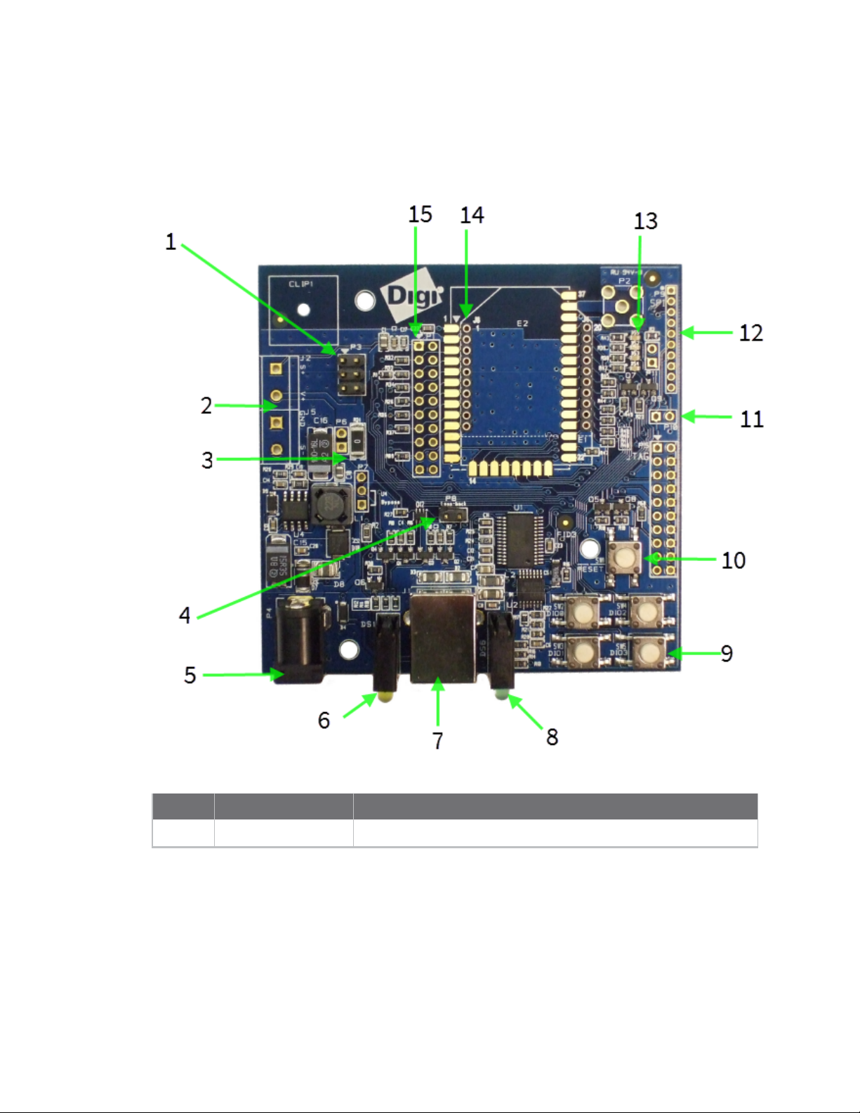
XBIB-U_DEV reference
This picture shows the XBIB-U development board and the table that follows explains the callouts in
the picture.
Number Item Description
1 Programmingheader Header used to program XBee Programmable devices.
Digi XBee Cellular LTE Cat 1 Embedded Modem User Guide
14
Page 15

Getting started with the XBee Cellular Modem Development Kit XBIB-U_DEV reference
Number Item Description
2 Self power module
Advanced users only—voids the warranty. Depopulate R31 to
power the device using V+ and GND from J2 and J5. You can
connect sense lines to S+ and S- for sensing power supplies.
CAUTION: Voltage is not regulated. Applying the incorrect
voltage can cause fire and serious injury.
1
3 Current testing Depopulating R31 allows a current probe to be inserted across P6
terminals. The current though P6/R31 powers the device only.
Other supporting circuitry is powered by a different trace.
4 Loopback jumper Populating P8 with a loopback jumper causes serial transmissions
both from the device and from the USB to loopback.
5 DC barrel plug: 6-20V Greater than 500 mA loads require a DC supply for correct
operation. Plug in the external power supply prior to the USB
connector to ensure that proper USB communications are not
interrupted.
6 LED indicator
Yellow: Modem sending serial/UART data to host.
Green: Modem receiving serial/UART data from host.
Red: Associate.
7 USB
8 RSSI indicator
9 User buttons Connected to DIO lines for user implementation.
10 Reset button
11 SPI power Connect to the power board from 3.3 V.
12 SPI Only used for surface-mount devices.
13 Indicator LEDs
DS5: ON/SLEEP
DS2: DIO12, the LED illuminates when driven low.
DS3: DIO11, the LED illuminates when driven low.
DS4: DIO4, the LED illuminates when driven low.
14 Through-hole XBee
sockets
15 20-pin header Maps to standard through-hole XBee pins.
1
Powering the board with J2 and J5 without R31 removed can cause shorts if the USB or barrel plug power are
connected. Applying too high a voltage destroys electronic circuitry in the device and other board components
and/or can cause injury.
Digi XBee Cellular LTE Cat 1 Embedded Modem User Guide
15
Page 16

Getting started with the XBee Cellular Modem Development Kit XBee Cellular Modem examples
XBee Cellular Modem examples
Check for cellular registration and connection
In the following examples, proper cellular network registration and address assignment must occur
successfully. The LED on the development board blinks when the XBee Cellular Modem registers to the
cellular network; see The Associate LED. If the LEDremains solid, registration has not occurred
properly. Registration can take several minutes.
Note Make sure you are in an area with adequate cellular network reception or the XBee Cellular
Modem will not make the connection.
In addition to the LED confirmation, you can check the AT commands below in XCTU to check the
registration and connection. To view these commands:
Open XCTU and click the Configuration working mode button.
1.
2. Select a device from the Radio Modules list. XCTU displays the current firmware settings for
that device.
On the Configuration toolbar, click the Default button to load the default values
3.
established by the firmware, and click Yes to confirm.
The relevant commands are:
Note To search for an ATcommand in XCTU, use the search box.
n AI (Association Indication) reads zero when the device successfully registers to the cellular
network. If it reads 0x23 it is connecting to the Internet; 0x22 means it is registering to the
cellular network.
n MY (Module IPAddress) should display a valid IPaddress. If it reads 0.0.0.0, it has not
registered yet.
n AN is not visible on the standard settings interface, it is an advanced command. See AN (APN).
Send an SMS message to a phone
The XBee Cellular Modem can send and receive Short Message Service (SMS) transmissions (texts)
while in Transparent mode. This allows you to send and receive text messages to and from an SMS
capable device such as a mobile phone.
The following table explains the AT commands that you use in this example.
Digi XBee Cellular LTE Cat 1 Embedded Modem User Guide
16
Page 17
Getting started with the XBee Cellular Modem Development Kit XBee Cellular Modem examples
Command Value Description
AP (APIEnable)
IP (IP Protocol)
P#
(DestinationPhone
Number)
TD (Text Delimiter)
PH (Module's SIM
phone number)
1. Ensure that the device is set up correctly with the SIM card installed and the antennas
connected as described in Connect the hardware.
Open XCTU and click the Configuration working mode button.
2.
3. Select a device from the Radio Modules list. XCTU displays the current firmware settings for
that device.
0 Set the device's API mode to Transparent mode.
2 Set the expected transmission mode to SMScommunication.
<Target
phone
number>
D (0x0D)
Read
only
The target phone number that you send to, for example, your
cellular phone. See P# (Destination Phone Number) for instructions
on using this command.
The text delimiter to be used for Transparent mode, as an ASCII hex
code. No information is sent until this character is entered, unless
the maximum number of characters has been reached. Set to zero
to disable text delimiter checking. Set to D for a carriage return.
The value that represents your device's phone number as supplied
by the SIM card. This is used to send text messages to the device
from another cellular device.
On the Configuration toolbar, click the Default button to load the default values
4.
established by the firmware, and click Yes to confirm.
5. Factory settings are loaded but not written to the device. To write them, click the Write button
on the toolbar.
To switch to SMS communication, in the IP field, select 2 and click the Write button .
6.
7. To enter your cell phone number, in the P# field, type the <target phone number> and click
the Write button. Type the phone number using only numbers, with no dashes. You can use the
+ prefix if necessary. The target phone number is the phone number you wish to send a text to.
8. In the TD field, type D and click the Write button.
9. Note the number in the PH field; it is the XBee Cellular Modem phone number, which you see
when it sends an SMS to your phone.
Digi XBee Cellular LTE Cat 1 Embedded Modem User Guide
17
Page 18

Getting started with the XBee Cellular Modem Development Kit XBee Cellular Modem examples
Click the Consoles working mode button on the toolbar to open a serial console to the
10.
device. For instructions on using the Console, see
http://www.digi.com/resources/documentation/digidocs/90001458-
13/default.htm#reference/r_at_console.htm
Click the Open button to open a serial connection to the device.
11.
12. Click in the left pane of the Console log, type hello world and press Enter. The XBee Cellular
Modem sends the message to the destination phone number set by the P# command.
13. When the phone receives the text, you can see that the sender's phone number matches the
value reported by the XBee Cellular Modem with the PH command.
14. On the phone, reply with the text connect with confidence and the XBee Cellular Modem
outputs this reply from the UART.
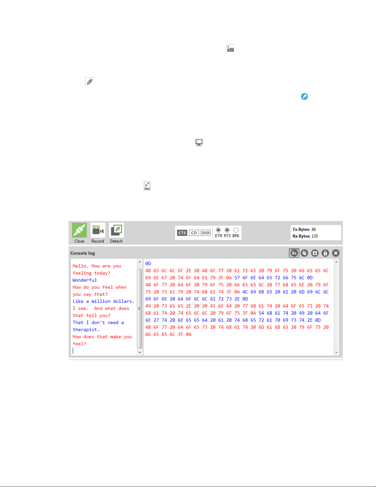
Connect to the ELIZA server
You can use the XBee Cellular Modem to chat with the ELIZA Therapist Bot. ELIZAis an artificial
intelligence (AI) bot that emulates a therapist and can perform simple conversations.
The following table explains the AT commands that you use in this example.
At command Value Description
IP (IP Protocol) 1 Set the expected transmission mode to TCP
communications.
DL (Destination
Address)
DE (Destination Port) 0x2328 The target port number of the Eliza server.
To communicate with the ELIZA Therapist Bot:
1. Ensure that the device is set up correctly with the SIM card installed and the antennas
connected as described in Connect the hardware.
Open XCTU and click the Configuration working mode button.
2.
3. Select a device from the Radio Modules list. XCTU displays the current firmware settings for
that device.
52.43.121.77 The target IP address of the Eliza server.
Digi XBee Cellular LTE Cat 1 Embedded Modem User Guide
18
Page 19
Getting started with the XBee Cellular Modem Development Kit XBee Cellular Modem examples
On the Configuration toolbar, click the Default button to load the default values
4.
established by the firmware, and click Yes to confirm.
5. Factory settings are loaded but not written to the device. To write them, click the Write button
on the toolbar.
To switch to TCP communication, in the IP field, select 1 and click the Write button .
6.
7. To enter the destination address of the ELIZATherapist Bot, in the DL field, type 52.43.121.77
and click the Write button.
8. To enter the destination IP port number, in the DE field, type 2328 and click the Write button.
Click the Consoles working mode button on the toolbar to open a serial console to the
9.
device. For instructions on using the Console, see
http://www.digi.com/resources/documentation/digidocs/90001458-
13/default.htm#reference/r_at_console.htm
Click the Open button to open a serial connection to the device.
10.
11. Click in the left pane of the Console log, then type in the Console to talk to the ELIZA Therapist
Bot. The following screenshot provides an example of this chat.
Connect to the echo server
This server echoes back the messages you type.
The following table explains the AT commands that you use in this example.
Digi XBee Cellular LTE Cat 1 Embedded Modem User Guide
19
Page 20

Getting started with the XBee Cellular Modem Development Kit XBee Cellular Modem examples
At
command Value Description
IP (IP
Protocol)
TD
(Text
Delimiter)
DL
(Destination
Address)
DE
(Destination
Port)
To communicate with the echo server:
1. Ensure that the device is set up correctly with the SIM card installed and the antennas
connected as described in Connect the hardware.
Open XCTU and click the Configuration working mode button.
2.
3. Select a device from the Radio Modules list. XCTU displays the current firmware settings for
that device.
1 Set the expected transmission mode to TCP communications.
D (0x0D)
52.43.121.77 The target IPaddress of the echo server.
0x2329 The target port number of the echo server.
The text delimiter to be used for Transparent mode, as an ASCII hex
code. No information is sent until this character is entered, unless the
maximum number of characters has been reached. Set to zero to
disable text delimiter checking. Set to D for a carriage return.
On the Configuration toolbar, click the Default button to load the default values
4.
established by the firmware, and click Yes to confirm.
5. Factory settings are loaded but not written to the device. To write them, click the Write button
on the toolbar.
To switch to TCP communication, in the IP field, select 1 and click the Write button .
6.
7. To enable the XBee Cellular Modem to recognize carriage return as a message delimiter, in the
TD field, type D and click the Write button.
8. To enter the destination address of the echo server, in the DL field, type 52.43.121.77 and click
the Write button.
9. To enter the destination IP port number, in the DE field, type 2329 and click the Write button.
Digi XBee Cellular LTE Cat 1 Embedded Modem User Guide
20
Page 21

Getting started with the XBee Cellular Modem Development Kit XBee Cellular Modem examples
Click the Consoles working mode button on the toolbar to open a serial console to the
10.
device. For instructions on using the Console, see
http://www.digi.com/resources/documentation/digidocs/90001458-
13/default.htm#reference/r_at_console.htm
Click the Open button to open a serial connection to the device.
11.
12. Click in the left pane of the Console log, then type in the Console to talk to the echo server.
The following screenshot provides an example of this chat.
Connect to the Daytime server
The Daytime server reports the current Coordinated Universal Time (UTC) value responding to any
user input.
The following table explains the AT commands that you use in this example.
At
command Value Description
IP (IP
Protocol)
DL
(Destination
Address)
DE
(Destination
Port)
TD (Text
Delimiter)
To communicate with the Daytime server:
1 Set the expected transmission mode to TCP communications.
52.43.121.77 The target IP of the Daytime server.
0x232A The target port number of the Daytime server.
0
The text delimiter to be used for Transparent mode, as an ASCII hex
code. No information is sent until this character is entered, unless the
maximum number of characters has been reached. Set to zero to
disable text delimiter checking.
Digi XBee Cellular LTE Cat 1 Embedded Modem User Guide
21
Page 22

Getting started with the XBee Cellular Modem Development Kit XBee Cellular Modem examples
1. Ensure that the device is set up correctly with the SIM card installed and the antennas
connected as described in Connect the hardware.
Open XCTU and click the Configuration working mode button.
2.
3. Select a device from the Radio Modules list. XCTU displays the current firmware settings for
that device.
On the Configuration toolbar, click the Default button to load the default values
4.
established by the firmware, and click Yes to confirm.
5. Factory settings are loaded but not written to the device. To write them, click the Write button
on the toolbar.
To switch to TCP communication, in the IP field, select 1 and click the Write button .
6.
7. To enter the destination address of the daytime server, in the DL field, type 52.43.121.77 and
click the Write button.
8. To enter the destination IP port number, in the DE field, type 232A and click the Write button.
9. To disable text delimiter checking, in the TD field, type 0 and click the Write button.
Click the Consoles working mode button on the toolbar to open a serial console to the
10.
device. For instructions on using the Console, see
http://www.digi.com/resources/documentation/digidocs/90001458-
13/default.htm#reference/r_at_console.htm
Click the Open button to open a serial connection to the device.
11.
12. Click in the left pane of the Console log, then type in the Console to query the Daytime server.
The following screenshot provides an example of this chat.
Digi XBee Cellular LTE Cat 1 Embedded Modem User Guide
22
Page 23

Getting started with the XBee Cellular Modem Development Kit XBee Cellular Modem examples
Connect to a TCP/IP address
The XBee Cellular Modem can send and receive TCP messages while in Transparent mode; see
Transparent operating mode.
You can use this example as a template for sending and receiving data from a user. The following table
explains the AT commands that you use in this example.
Command Value Description
IP (IP
Protocol)
DL
(Destination
IPAddress)
DE
(Destination
Port)
To connect to a TCP/IP address:
1. Ensure that the device is set up correctly with the SIM card installed and the antennas
connected as described in Connect the hardware.
Open XCTU and click the Configuration working mode button.
2.
3. Select a device from the Radio Modules list. XCTU displays the current firmware settings for
that device.
1 Set the expected transmission mode to TCPcommunication.
<Target
IPaddress>
<Target
portnumber>
The target IP address that you send and receive from. For example, a
data logging server’s IP address that you want to send
measurements to.
The target port number that the device sends the transmission to.
This is represented as a hexadecimal value.
Digi XBee Cellular LTE Cat 1 Embedded Modem User Guide
23
Page 24

Getting started with the XBee Cellular Modem Development Kit XBee Cellular Modem examples
On the Configuration toolbar, click the Default button to load the default values
4.
established by the firmware, and click Yes to confirm.
5. Factory settings are loaded but not written to the device. To write them, click the Write button
on the toolbar.
In the IP field, select 1 and click the Write button .
6.
7. In the DL field, type the <target IP address> and click the Write button. The target IP address
is the IPaddress that you send and receive from.
8. In the DE field, type the <target port number>, converted to hexadecimal, and click the Write
button.
9. Exit Command mode; see Exit Command mode.
After exiting Command mode, any UART data sent to the device is sent to the destination IP address
and port number after the RO (Packetization Timeout) occurs.
Perform a (GET) HTTP request
You can use the XBee Cellular Modem to perform a GET Hypertext Transfer Protocol (HTTP) request
using XCTU. This example uses http://httpbin.org/ (IP address: 54.175.219.8) as the target website
that responds to the HTTP request.
To perform a GETrequest:
1. Ensure that the device is set up correctly with the SIM card installed and the antennas
connected as described in Connect the hardware.
Open XCTU and click the Configuration working mode button.
2.
3. Select a device from the Radio Modules list. XCTU displays the current firmware settings for
that device.
4. To enter the destination address of the target website, in the DL field, type 54.175.219.8 and
click the Write button .
5. To enter the HTTP request port number, in the DE field, type 50 and click the Write button.
Hexadecimal 50 is 80 in decimal.
6. To switch to TCP communication, in the IP field, select 1 and click the Write button.
7. To move into Transparent mode, in the APfield, select 0 and click the Write button.
8. Wait for the AI (Association Indication) value to change to 0 (Connected to the Internet).
Click the Consoles working mode button on the toolbar.
9.
From the AT console, click the Add new packet button in the Send packets dialog. The
10.
Add new packet dialog appears.
11. Enter the name of the data packet.
12. Type the following data in the ASCII input tab:
GET /ip HTTP/1.1
Digi XBee Cellular LTE Cat 1 Embedded Modem User Guide
24
Page 25

Getting started with the XBee Cellular Modem Development
Kit
Host: httpbin.org
13. Click the HEX input tab and add 0A (zero A) after each 0D (zero D), and add an additional 0D 0A
at the end of the message body. For example, copy and past the following text into the HEX
input tab:
47 45 54 20 2F 69 70 20 48 54 54 50 2F 31 2E 31 0D 0A 48 6F 73 74 3A 20 68 74 74 70 62 69 6E
2E 6F 72 67 0D 0A 0D 0A
Note The HTTP protocol requires an empty line (a line with nothing preceding the CRLF) to terminate
the request.
14. Click Add packet.
Click the Open button .
15.
16. Click Send selected packet.
17. A GETHTTP response from httpbin.org appears in the Console log.
Configure the XBee Cellular Modem using Device
Configure the XBee Cellular Modem using Device Cloud
Cloud
Create a Device Cloud account
Digi Device Cloud is an on-demand service with no infrastructure requirements. Remote devices and
enterprise business applications connect to Device Cloud through standards-based web services. This
section describes how to configure and manage an XBee using Device Cloud. For detailed information
on using Device Cloud, refer to the Device Cloud User Guide, available via the Documentation tab in
Device Cloud.
Before you can manage an XBee with Device Cloud, you must create a Device Cloud account. To create
a Device Cloud account:
1. Go to www.digi.com/cloud/digi-device-cloud.
2. Click Free Developer Account.
3. Follow the online instructions to complete account registration. You can upgrade your
Developer account to a paid account at any time.
When you are ready to deploy multiple XBee Cellular Modems in the field, upgrade your account to
access additional Device Cloud features.
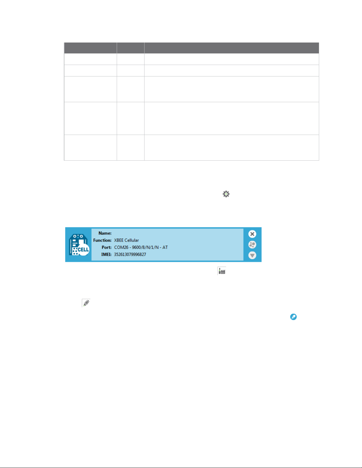
Get the XBee Cellular Modem IMEI number
Before adding an XBee to your Device Cloud account inventory, you need to determine the
International Mobile Equipment Identity (IMEI) number for the device. Use XCTUto view the IMEI
number by querying the IM parameter.
Add a Digi XBee to Device Cloud
To add an XBee to your Device Cloud account inventory, follow these steps:
Go to devicecloud.digi.com.
1. Log in to your account
2. Click Device Management > Devices.
Digi XBee Cellular LTE Cat 1 Embedded Modem User Guide
25
Page 26

Getting started with the XBee Cellular Modem Development
Kit
3. Click Add Devices. The Add Devices dialog appears.
You can use the Discover button to discover an XBee device if the XBee is connected to your
local network.
4. Select IMEI#, and type or paste the IMEI number of the XBee you want to add. The IM
(IMEI)command provides this number.
5. Click Add to add the device. The XBee is added to your inventory.
Configure the XBee Cellular Modem using Device
Cloud
6. Click OK to close the Add Devices dialog and return to the Devices view.
Update the firmware
XBee Cellular Modem supports Device Cloud firmware updates. To perform a firmware update, use
the following steps.
1. Download the updated firmware file for your device from Digi's support site. This is a zip file
containing .ebin and .mxi files for import.
2. Unzip the file.
3. In your Device Cloud account, click Device Management > Devices.
4. Select the first device you want to update.
5. To select multiple devices (must be of the same type), press the Control key and select
additional devices.
6. Click More in the Devices toolbar and select Update Firmware from the Update category of
the More menu. The Update Firmware dialog appears.
7. Click Browse to select the .ebin file that you unzipped earlier.
8. Click Update Firmware. The updated devices automatically reboot when the updates are
complete.
Digi XBee Cellular LTE Cat 1 Embedded Modem User Guide
26
Page 27

Technical specifications
Interface and hardware specifications 28
RF characteristics 28
Networking and carrier 28
Power requirements 28
Power consumption 29
Electrical specifications 29
Regulatory approvals 30
Digi XBee Cellular LTE Cat 1 Embedded Modem User Guide
27
Page 28

Technical specifications Interface and hardware specifications
Interface and hardware specifications
The following table provides the interface and hardware specifications for the device.
Specification Value
Dimensions 2.438 x 3.294 cm (0.960 x 1.297 in)
Weight 5 g (0.18 oz)
Operating temperature -40 to +80 °C
Antenna connector U.FL for primary and secondary antennas
Digital I/O 13 I/O lines
ADC 4 10-bit analog inputs
RF characteristics
The following table provides the RF characteristics for the device.
Specification Value
Modulation LTE/4G – QPSK, 16 QAM
Transmit power 23 dBm
Receive sensitivity -102 dBm
Over-the-air maximum data rate 10 Mb/s
Data throughput TBD
Networking and carrier
The following table provides the networking and carrier specifications for the device.
Specification Value
Addressing options TCP/IPand SMS
Carrier and technology Verizon 4G LTE Cat 1
Supported bands 4 and 13
Security SSL/TLS
Power requirements
The following table provides the power requirements for the device.
Digi XBee Cellular LTE Cat 1 Embedded Modem User Guide
28
Page 29

Technical specifications Power consumption
Specification Value
Supply voltage 3.0 to 5.5 V
Extended voltage range 2.7 to 5.5 VDC
Power consumption
The peak current was measured from multiple tested units.
Specification State Average current Measured peak current
Tx+RX current Active transmit, 23 dBm @ 3.3 V 860 mA 1020 mA
Tx+RX current Active transmit, 23 dBm @ 5.0 V 555 mA 630 mA
TX Only current Activetransmit,23dBm@3.3V 680 mA N/A
Rx + ACK current Active receive @ 3.3 V 530 mA N/A
Rx + ACK current Active receive @ 5 V 360 mA N/A
RX Only current Active receive @ 3.3 V 300 mA N/A
Idle current Idle/connected, listening @ 3.3 V 143 mA N/A
Idle current Idle/connected, listening @ 5 V 100 mA N/A
Sleep current Notconnected,Deep Sleep@3.3V 10 µA N/A
Electrical specifications
Symbol Parameter Condition Min Typical Max Units
VCCMAX Maximum limits
of VCC line
VDD_IO Supply voltage
for I/O
VDD_IO Supply voltage
for I/O
VI Voltage on any
pin
VIL Input low voltage 0.3*VDD_
0 5.5 V
While in deep sleep and
during initial power up
In normal running mode 3.3 V
Min
(VCC-
0.3,3.3)
-0.3 VDD_IO +
3.3 V
V
0.3
IO
VIH Input high
voltage
Digi XBee Cellular LTE Cat 1 Embedded Modem User Guide
0.7*VDD_
IO
29
Page 30

Technical specifications Regulatory approvals
Symbol Parameter Condition Min Typical Max Units
VOL Voltage output
low
VOH Voltage output
high
II_IN Input leakage
current
RPU Internal pull-up
resistor
RPD Internal pull-
down resistor
Regulatory approvals
The following table provides the regulatory and carrier approvals for the device.
Specification Value
United States Contains FCC ID: RI7LE866SV1
Industry Canada Contains IC: 5131A-LE866SV1
Europe (CE) N/A
Sinking 6 mA VDD_IO = 3.3 V 0.2*VDD_
IO
Sourcing 6 mA VDD_IO = 3.3 V 0.75*VDD_
IO
High Z state I/O connected
to Ground or VDD_IO
Enabled 40 kΩ
Enabled 40 kΩ
0.1 100 nA
RoHS Lead-free and RoHS compliant
Australia N/A
Digi XBee Cellular LTE Cat 1 Embedded Modem User Guide
30
Page 31

Hardware
Mechanical drawings 32
Pin signals 32
Antenna connections 33
Antenna placement 34
SIM card 34
The Associate LED 34
Heat considerations 35
Heat sink considerations 35
Power supply considerations 36
Add a capacitor to the RESET line 36
Add a fan to provide active cooling 37
Digi XBee Cellular LTE Cat 1 Embedded Modem User Guide
31
Page 32

Hardware Mechanical drawings
Mechanical drawings
The following figures show the mechanical drawings for the XBee Cellular Modem. The drawings do
not show antenna options. All dimensions are in inches.
Pin signals
The following table shows the pin assignments for the through-hole device. In the table, low-asserted
signals have a horizontal line above signal name.
Pin Name Direction Default Description
Pin Name Direction Default Description
1
2 DOUT Output Output UART Data Out
3
4 DIO12 Either Digital I/O 12
5 RESET Input
6 PWM0 / RSSI / DIO10 Either Output PWM Output 0 / RX Signal
V
CC
DIN / CONFIG
Power supply
Input Input UART Data In
Strength Indicator / Digital
I/O10
Digi XBee Cellular LTE Cat 1 Embedded Modem User Guide
32
Page 33

Hardware Antenna connections
Pin Name Direction Default Description
7 PWM1 / DIO11 Either PWM Output 1 / Digital I/O
11
8 [reserved] Do not connect
DTR / SLEEP_RQ/ DIO8
9
10 GND Ground
11 DIO4 Either Digital I/O 4
CTS / DIO7
12
ON /SLEEP/DIO9
13
14 VREF Unused This line is not connected.
15 Associate / DIO5 Either Output Associated Indicator,
Either Output Output Clear-to-Send Flow
Output Output Module Status Indicator or
Pin Sleep Control Line or
Digital I/O 8
Control or Digital I/O 7
Digital I/O 9
It is used on other XBee
products.
Digital I/O 5
RTS / DIO6
16
AD3/DIO3
17
18 AD2 / DIO2 Either Disabled Analog Input 2 or Digital
AD1/DIO1
19
20 AD0/DIO0 Either Input Analog Input 0, Digital I/O
Pin connection recommendations
The only required pin connections are VCC, GND, DIN, DOUT, RTS, DTR and RESET. Firmware updates
require access to these pins.
Antenna connections
CAUTION! The XBee Cellular Modem will not function properly with only the secondary
antenna port connected!
Either Disabled Input Request-to-Send
Flow Control, Digital I/O 6
Either Disabled Analog Input 3 or Digital
I/O 3
I/O 2
Either Disabled
Analog Input 1 or Digital
I/O 1
0
The XBee Cellular Modem has two U.FL antenna ports; a primary on the upper left of the board and a
secondary port on the upper right, see the drawing below. You must connect the primary port and the
Digi XBee Cellular LTE Cat 1 Embedded Modem User Guide
33
Page 34

Hardware Antenna placement
secondary port is optional. The secondary antenna improves receive performance in certain
situations, so we recommend it for best results.
Antenna placement
It is important to keep the antenna as far away from the XBee Cellular Modem and other metal
objects as possible. Often, small antennas are desirable, but at the cost of increasing size of dead
zones because of reduced range and efficiency.
We recommend that antennas do not touch each other, but the XBee Cellular Modem works if they do.
To optimize receive performance, orient the two antennas at right angles to each other.
SIM card
The XBee Cellular Modem uses the 4FF/nano SIM card size.
CAUTION! Never insert or remove SIM card while the power is on!
The Associate LED
The following table describes the Associate LED functionality. For the location of the Associate LED on
the XBIB-U development board, see number 6 on the XBIB-U_DEV reference.
LED status
Blink
timing Meaning
On, solid Not joined to a mobile network.
Digi XBee Cellular LTE Cat 1 Embedded Modem User Guide
34
Page 35

Hardware Heat considerations
Blink
LED status
timing Meaning
Double blink
Standardsingleblink
The normal association LED signal alternates evenly between high and low as shown below:
Where the low signal means LED off and the high signal means LED on.
When CI is not 0 or 0xFF, the Associate LED has a different blink pattern that looks like this:
Heat considerations
Depending on the use case, your application may require a heat sink. Use a non-conductive thermal
gasket to make contact to the heat sink. The gasket should be thick enough to ensure that contact
with the tallest component does not cause damage when pressure is applied to a secure heat sink.
We recommend connecting the heat sink to the top side of the XBee Cellular Modem without covering
the U.FL connectors.
We do not recommend operating the unit above 80 °C.
The operation temperature of the unit can be approximated for different current draws and extreme
cases by the equation below. For best results, attach a temperature probe just above the center of
the XBee Cellular Modem. Alternatively use TP (Temperature) to query the current temperature of the
device's processor.
½second
1second
The last TCP/UDP/SMS attempt failed. If the LED has this pattern,
you may need to check DI (Device Cloud Indicator) or CI
(Protocol/Connection Indication) for the cause of the error.
Normal operation.
Where
1. XBeeBoardTemp is the temperature of the XBee Cellular Modem at steady state.
a. Use the TPcommand to help estimate the temperature when attaching a
temperature probe is not practical, but for reliable results, you must use a
temperature probe.
2. RoomTemp is the temperature of the ambient air.
3. AverageCurrentDuringTest is the average current measured during test.
4. ScenarioMaxCurrent is the maximum current expected for the device.
Heat sink considerations
The following table provides a set of typical heat sink examples for scenarios that customers may
encounter.
Digi XBee Cellular LTE Cat 1 Embedded Modem User Guide
35
Page 36

Hardware Power supply considerations
The results may vary by implementation and scenario. You should always perform sufficient testing to
ensure that the XBee Cellular Modem does not exceed temperature specifications.
Maximum ambient
temperature
3.3 V
average
Scenario
Maximum
current
50% current 475 mA Running low-resolution
20% current 200 mA Sending 2 MB picture of
Device available 170 mA Updating traffic sign 1 to 10 66 °C 71 °C 78 °C
Sleep current
scenario—high
latency
current Scenario example
950 mA Running video camera 200 to 2000 NR131°C 70°C
camera
traffic every minute
20 mA Wakes at most once per
hour to send and/or
receive data
Power supply considerations
When considering a power supply, use the following design practices.
1. Keep power supply ripple below 75 mV.
2. The supply should handle 1.5 A.
3. Place sufficient bulk capacitance on the VCC to maintain voltage above the minimum
specification during inrush current. Inrush current is about 2 A during initial power up of cellular
communications and during cellular restart conditions.
Peak MB
consumed
per hour
80 to 500 42°C 55°C 75°C
10 to 100 64 °C 70 °C 78 °C
Less than 0.1 78 °C 78 °C 78 °C
No
heat
sink
Heat
sink
Heat
sink
and fan
4. Place smaller high frequency ceramic capacitors very close to the XBee Cellular Modem VCC
pin to decrease high frequency noise.
5. The power supply trace must be thick enough to handle the current requirements with minimal
voltage drop when peak currents are reached. Lower voltages require more current to achieve
the same power output. Supply voltage steady state at VCC pin 1 should change by less than
0.1 V if drawing 0.5 W compared to drawing 2.8 W.
Add a capacitor to the RESET line
In high EMI noise environments, we recommend adding a 10 nF ceramic capacitor very close to pin 5.
1
NR = not recommended.
Digi XBee Cellular LTE Cat 1 Embedded Modem User Guide
36
Page 37

Hardware Add a fan to provide active cooling
Add a fan to provide active cooling
The XBee Cellular Modem can become hot if you use it in the maximum upload or download scenarios,
see Heat considerations. You can attach a fan to the device to provide active cooling.
If you attach a fan, use P1 (DIO11/PWM1 Configuration) to enable this functionality on pin 7. Set P1 to
1, which turns the fan on when the device gets above 70 °C and the cellular component is running, and
off below 65 °C.
Digi XBee Cellular LTE Cat 1 Embedded Modem User Guide
37
Page 38

Cellular connection process
Connecting 39
Cellular network 39
Data network connection 39
Data communication with remote servers (TCP/UDP) 39
Disconnecting 39
SMS encoding 40
Digi XBee Cellular LTE Cat 1 Embedded Modem User Guide
38
Page 39

Cellular connection process Connecting
Connecting
In normal operations, the XBee Cellular Modem automatically attempts both a cellular network
connection and a data network connection on power-up. The sequence of these connections is as
follows:
Cellular network
1. The device powers on.
2. It looks for cellular towers.
3. It chooses a candidate tower with the strongest signal.
4. It negotiates a connection.
5. It completes cellular registration; the phone number and SMS are available.
Data network connection
1. The network enables the evolved packet system (EPS) bearer with an access point name
(APN). See AN (APN) if you have APNissues.
2. The device negotiates a data connection with the access point.
3. The device receives its IP configuration and address.
4. The AI (Association Indication) command now returns a 0 and the sockets become available.
Data communication with remote servers (TCP/UDP)
Once sockets become available, communication with remote servers can be initiated in several ways:
n Transparent mode data received over a serial connection (see TD (Text Delimiter) and RO
(Packetization Timeout) for timing).
n API mode: Transmit (TX) Request: IPv4 - 0x20 received over the serial connection.
n Digi Remote Manager connectivity begins.
Data communication begins when:
1. A socket opens to the remote server.
2. Data is sent.
3. The XBee Cellular Modem listens for incoming data.
Data connectivity ends when:
1. The server closes the connection.
2. The TM timeout expires (see TM (TCP Client Connection Timeout)).
3. The cellular network may also close the connection after a timeout set by the network
operator.
Disconnecting
When the XBee Cellular Modem is put into Airplane mode or deep sleep is requested:
Digi XBee Cellular LTE Cat 1 Embedded Modem User Guide
39
Page 40

Cellular connection process SMS encoding
1. Sockets are closed, cleanly if possible.
2. The EPS bearer data connection is shut down.
3. The cellular connection is shut down.
4. The cellular component is powered off.
SMS encoding
The XBee Cellular Modem transmits SMS messages using the standard GSM 03.38 character set.
Because this character set only provides 7 bits of space per character, the XBee Cellular Modem
ignores the most significant bit of each octet in an SMS transmission payload.
The device converts incoming SMS messages to ASCII. Characters that cannot be represented in
ASCIIare replaced with a space (' ', or 0x20 in hex). This includes emoji and other special characters.
1
1
Also referred to as the GSM 7-bit alphabet.
Digi XBee Cellular LTE Cat 1 Embedded Modem User Guide
40
Page 41

Modes
Select an operating mode 42
Transparent operating mode 42
API operating mode 43
Bypass operating mode 43
Command mode 44
Digi XBee Cellular LTE Cat 1 Embedded Modem User Guide
41
Page 42

Modes Select an operating mode
Select an operating mode
The XBee Cellular Modem interfaces to a host device such as a microcontroller or computer through a
logic-level asynchronous serial port. It uses a UART for serial communication with those devices.
The XBee Cellular Modem supports three operating modes: Transparent operating mode,
APIoperating mode, and Bypass operating mode. The default mode is Transparent operating mode.
Use the AP (API Enable) command to select a different operating mode.
The following flowchart illustrates how the modes relate to each other.
Transparent operating mode
Devices operate in this mode by default. The device acts as a serial line replacement when it is in
Transparent operating mode. The device queues all serial data it receives through the DIN pin for RF
transmission. When a device receives RF data, it sends the data out through the DOUT pin. You can set
the configuration parameters using Command mode.
Digi XBee Cellular LTE Cat 1 Embedded Modem User Guide
42
Page 43

Modes API operating mode
The IP (IP Protocol) command setting controls how Transparent operating mode works for the XBee
Cellular Modem.
API operating mode
API operating mode is an alternative to Transparent operating mode. API mode is a frame-based
protocol that allows you to direct data on a packet basis. The device communicates UART data in
packets, also known as API frames. This mode allows for structured communications with computers
and microcontrollers.
The advantages of APIoperating mode include:
n It is easier to send information to multiple destinations
n The host receives the source address for each received data frame
n You can change parameters without entering Command mode
Bypass operating mode
CAUTION! Bypass operating mode is an alternative to Transparent and API modes for
advanced users with special configuration needs. Changes made in this mode might
change or disable the device and we do not recommended it for most users.
In Bypass mode, the device acts as a serial line replacement to the cellular component. In this mode,
the XBee Cellular Modem exposes all control of the cellular component's AT port through the UART.
Note The cellular component can become unresponsive in Bypass mode. See Unresponsive cellular
component in Bypass mode for help in this situation.
When Bypass mode is active, most of the XBee Cellular Modem's AT commands do not work. For
example, IM (IMEI)may never return a value, and DB does not update.
When entering Bypass mode, the device terminates all existing socket connections. This includes the
Device Cloud connection if it is currently enabled. When leaving Bypass mode, the device reestablishes a Device Cloud connection if the Device Cloud connection setting is currently enabled.
Command mode is available while in Bypass mode; see Enter Command mode for instructions.
Enter Bypass operating mode
To configure a device for Bypass operating mode:
1. Set the AP (APIMode) parameter value to 5.
2. Use AC (Apply Changes) or CN (Exit Command Mode)to apply the changes.
3. To verify that Bypass operating mode is active, query AI (Association Indication) and confirm
that it returns a value of 0x2F.
It may take a moment for Bypass operating mode to become active.
Leave Bypass operating mode
To configure a device to leave Bypass operating mode:
Digi XBee Cellular LTE Cat 1 Embedded Modem User Guide
43
Page 44

Modes Command mode
1. Set the AP (APIMode) parameter value to something other than 5.
2. Use AC (Apply Changes) or CN (Exit Command Mode)to apply the changes.
3. To verify that Bypass operating mode is not active, query AI (Association Indication) and
confirm that it returns something other than 0x2F.
Boot the XBee Cellular Modem in Bypass operating mode
If the host sends WR (Write) when AP (APIMode) is set to 5, it enables Bypass operating mode when
the XBee Cellular Modem turns on. In this configuration, the firmware does not test communication
with the cellular component (which it does by sending AT commands). This is useful in case you have
reconfigured the cellular component in a way that makes it incompatible with the firmware.
The option to boot with Bypass operating mode enabled exists for users who wish to communicate
directly with the cellular component settings and do not intend to use XBee Cellular Modem software
features such as API mode.
Note When the XBee Cellular Modem has been booted with Bypass operating mode enabled, disabling
Bypass operating mode causes the XBee Cellular Modem firmware to reboot the cellular modem.
Restore cellular settings to default in Bypass operating mode
Send AT&F1 to reset the cellular component to its factory profile.
Command mode
The three operating modes are controlled by the AP (API Enable) setting, but Command mode is
always available as a mode the device can enter while configured for any of the operating modes.
Enter Command mode
To get a device to switch into this mode, you must issue the following sequence: +++ within one
second. There must be at least one second preceding and following the +++ sequence. Both the
command character (CC) and the silence before and after the sequence (GT) are configurable. When
the device sees a full second of silence in the data stream (the guard time, GT) followed by the string
+++ (without Enter or Return) and another full second of silence, it knows to stop sending data and
start accepting commands locally.
Note Do not press Return or Enter after typing +++ because it will interrupt the guard time silence
and prevent you from entering Command mode.
When the device is in Command mode, it listens for user input and is able to receive AT commands on
the UART. If CT time (default is 10 seconds) passes without any user input, the device drops out of
Command mode and returns to the previous operating mode (Transparent, Bypass, API, Python, and
so forth).
You can customize the command character, the guard times and the timeout in the device’s
configuration settings. For more information, see CC (Command Sequence Character), CT (Command
Mode Timeout) and GT (Guard Times).
Troubleshooting
Failure to enter Command mode is often due to baud rate mismatch. Ensure that the baud rate of the
connection matches the baud rate of the device. By default, the BD parameter = 3 (9600 b/s).
Digi XBee Cellular LTE Cat 1 Embedded Modem User Guide
44
Page 45

Modes Command mode
There are two alternative ways to enter Command mode:
n A serial break for six seconds enters Command mode. The "break" command can be issued
from a serial console, and is often a button or menu item.
n Asserting DIN (serial break) upon power up or reset enters Command mode. XCTU guides you
through a reset and automatically issues the break when needed.
Both of these methods temporarily set the device's baud rate to 9600 and return an OK on the UART
to indicate that Command mode is active. When Command mode exits, the device returns to normal
operation at the baud rate the BD parameter is set to.
Send AT commands
Once the device enters Command mode, use the syntax in the following figure to send AT commands.
Every AT command starts with the letters AT, which stands for "attention." The AT is followed by two
characters that indicate which command is being issued, then by some optional configuration values.
To read a parameter value stored in the device’s register, omit the parameter field.
The preceding example changes the IP protocol to SMS.
Response to AT commands
When reading parameters, the device returns the current parameter value instead of an OK message.
Apply command changes
Any changes you make to the configuration command registers using AT commands do not take effect
until you apply the changes. For example, if you send the BD command to change the baud rate, the
actual baud rate does not change until you apply the changes. To apply changes:
1. Send the AC (Apply Changes) command.
or:
2. Exit Command mode.
Make command changes permanent
Issue a WR (Write) command to save the changes. WR writes parameter values to non-volatile
memory so that parameter modifications persist through subsequent resets.
Exit Command mode
1. Send the CN (Exit Command Mode) command followed by a carriage return.
or:
Digi XBee Cellular LTE Cat 1 Embedded Modem User Guide
45
Page 46

Modes Command mode
2. If the device does not receive any valid AT commands within the time specified by CT
(Command Mode Timeout), it returns to Transparent or API mode. The default Command Mode
Timeout is 10 seconds.
For an example of programming the device using AT Commands and descriptions of each configurable
parameter, see AT commands.
Digi XBee Cellular LTE Cat 1 Embedded Modem User Guide
46
Page 47

Sleep modes
About sleep modes 48
Normal mode 48
Pin sleep mode 48
Cyclic sleep mode 48
Cyclic sleep with pin wake up mode 48
Airplane mode 48
The sleep timer 48
Digi XBee Cellular LTE Cat 1 Embedded Modem User Guide
47
Page 48

Sleep modes About sleep modes
About sleep modes
A number of low-power modes exist to enable devices to operate for extended periods of time on
battery power. Use SM (Sleep Mode) to enable these sleep modes.
Normal mode
Set SM to 0 to enter Normal mode.
Normal mode is the default sleep mode. If a device is in this mode, it does not sleep and is always
awake.
Devices in Normal mode are typically mains powered.
Pin sleep mode
Set SM to 1 to enter pin sleep mode.
Pin sleep allows the device to sleep and wake according to the state of the SLEEP_RQ pin (pin 9).
When you assert SLEEP_RQ (high), the device finishes any transmit or receive operations, closes any
active connection, and enters a low-power state.
When you de-assert SLEEP_RQ (low), the device wakes from pin sleep.
Cyclic sleep mode
Set SM to 4 to enter Cyclic sleep mode.
Cyclic sleep allows the device to sleep for a specific time and wake for a short time to poll.
If you use the D7 command to enable hardware flow control, the CTS pin asserts (low) when the
device wakes and can receive serial data, and de-asserts (high) when the device sleeps.
Cyclic sleep with pin wake up mode
Set SM to 5 to enter Cyclic sleep with pin wake up mode.
This mode is a slight variation on Cyclic sleep mode (SM = 4) that allows you to wake a device
prematurely by de-asserting the SLEEP_RQ pin (pin 9).
In this mode, you can wake the device after the sleep period expires, or if a high-to-low transition
occurs on the SLEEP_RQ pin.
Airplane mode
While not technically a sleep mode, airplane mode is another way of saving power. When set, the
cellular component of the XBee Cellular Modem is fully turned off and no access to the cellular
network is performed or possible. Use AM (Airplane Mode) to configure this mode.
The sleep timer
If the device receives serial or RF data in Cyclic sleep mode and Cyclic sleep with pin wake up modes
(SM = 4 or SM = 5), it starts a sleep timer (time until sleep).
n Use ST (Wake Time) to set the duration of the timer.
n When the sleep timer expires the device returns to sleep.
Digi XBee Cellular LTE Cat 1 Embedded Modem User Guide
48
Page 49

AT commands
Special commands 50
Cellular commands 51
Network commands 53
Addressing commands 54
Serial interfacing commands 57
I/O settings commands 59
I/O sampling commands 61
Command mode options 62
Firmware version/information commands 63
Diagnostic interface commands 64
Execution commands 66
Digi XBee Cellular LTE Cat 1 Embedded Modem User Guide
49
Page 50

AT commands Special commands
Special commands
The following commands are special commands.
AC (Apply Changes)
Immediately applies new settings without exiting Command mode.
Applying changes means that the device re-initializes based on changes made to its parameter values.
Once changes are applied, the device immediately operates according to the new parameter values.
This behavior is in contrast to issuing the WR (Write) command. The WR command saves parameter
values to non-volatile memory, but the device still operates according to previously saved values until
the device is rebooted or you issue the CN (Exit AT Command Mode) or AC commands.
Parameter range
N/A
Default
N/A
FR (Force Reset)
Resets the device. The device responds immediately with an OK and performs a reset 100 ms later.
Parameter range
N/A
Default
N/A
RE (Restore Defaults)
Restore device parameters to factory defaults.
The RE command does not write restored values to non-volatile (persistent) memory. Issue the WR
(Write) command after issuing the RE command to save restored parameter values to non-volatile
memory.
Parameter range
N/A
Default
N/A
WR (Write)
Writes parameter values to non-volatile memory so that parameter modifications persist through
subsequent resets.
Note Once you issue a WR command, do not send any additional characters to the device until after
you receive the OK response.
Digi XBee Cellular LTE Cat 1 Embedded Modem User Guide
50
Page 51

AT commands Cellular commands
Parameter range
N/A
Default
N/A
Cellular commands
The following AT commands are cellular configuration and data commands.
PH (Phone Number)
Reads the SIM card phone number. If PH is blank, the XBee Cellular Modem is not registered to the
network.
Parameter range
N/A
Default
Set by the cellular carrier via the SIM card
S# (ICCID)
Reads the Integrated Circuit Card Identifier (ICCID) of the inserted SIM.
Parameter range
N/A
Default
Set by the SIMcard
IM (IMEI)
Reads the device's International Mobile Equipment Identity (IMEI).
Parameter range
N/A
Default
Set in the factory
MN (Operator)
Reads the network operator on which the device is registered.
Parameter range
N/A
Default
Verizon
Digi XBee Cellular LTE Cat 1 Embedded Modem User Guide
51
Page 52

AT commands Cellular commands
MV (Modem Firmware Version)
Read the firmware version string for cellular component communications. See the related VR
(Firmware Version) command.
Parameter range
N/A
Default
Set in the currently loaded firmware
DB (Cellular Signal Strength)
Reads the absolute value of the current signal strength to the cell tower in dB. If DB is blank, the XBee
Cellular Modem has not received a signal strength from the cellular component.
Parameter range
0x71 - 0x33 (-113 dBm to -51 dBm) [read-only]
Default
N/A
AM (Airplane Mode)
When set, the cellular component of the XBee Cellular Modem is fully turned off and no access to the
cellular network is performed or possible.
Parameter range
0 - 1
0 = Normal operation
1 = Airplane mode
Default
0
DV (Antenna Diversity)
Set and read the antenna diversity setting of the cellular component. When enabled, the cellular
component uses both antennas to improve receive sensitivity.
This setting is applied only while the XBee Cellular Modem is initializing the cellular component. After
changing this setting, you must:
1. Use WR (Write) to write all values to flash.
2. Use FR (Force Reset) to reset the device.
3. Wait for the cellular component to be initialized: AI (Association Indication) reaches 0x00.
4. Use FR to reset the device a second time.
5. Wait again for the cellular component to initialize:AI reaches 0x00.
Parameter range
0 - 1
Digi XBee Cellular LTE Cat 1 Embedded Modem User Guide
52
Page 53

AT commands Network commands
0 - diversity disabled
1 - diversity enabled
Default
1
Network commands
The following commands are network commands.
IP (IP Protocol)
Sets or displays the IP protocol used for client and server socket connections in IP socket mode.
Parameter range
Value Description
0x00 UDP
0x01 TCP
0x02 SMS
0x03 Reserved
0x04 SSL over TCPcommunication
Default
0x01
TL (SSL/TLS Protocol Version)
Sets the SSL/TLS protocol version used for the SSL socket. If you change the TL value, it does not
affect any currently open sockets. The value only applies to subsequently opened sockets.
Note Due to known vulnerabilities in prior protocol versions, we strongly recommend that you use the
latest TLS version whenever possible.
Range
Value Description
0x00
0x01
SSL v3
TLS v1.0
0x02
0x03
Default
0x03
Digi XBee Cellular LTE Cat 1 Embedded Modem User Guide
TLS v1.1
TLS v1.2
53
Page 54

AT commands Addressing commands
TM (TCP Client Connection Timeout)
Sets or reads the TCP client connection timeout. If there is no activity for this timeout then the
connection is closed. If you set TMto 0, the connection is closed immediately after the device sends
data.
If you change the TM value while in Transparent Mode, the current connection is immediately closed.
Upon the next transmission, the TM value applies to the newly created socket.
If you change the TM value while in API Mode, the value only applies to subsequently opened sockets.
Parameter range
0 - 0xFFFF [x 100 ms]
Default
0xBB8 (5 minutes)
DO (Device Options)
Sets or displays whether Device Cloud support is enabled.
If the XBee Cellular Modem cannot establish a connection with Device Cloud, it waits 30 seconds
before trying again. On each successive connection failure, the wait time doubles (60 seconds, 120,
240, and so on) up to a maximum of 1 hour. This time resets to 30 seconds once the connection to
Device Cloud succeeds or if the device is reset.
Range
Value Description
0x00 Device Cloud support is disabled.
0x01 Device Cloud support is enabled.
Default
0x01
EQ (Device Cloud FQDN)
Sets or display the fully qualified domain name of the Device Cloud server.
Range
From 0 through 63 ASCII characters.
Default
my.devicecloud.com
Addressing commands
The following AT commands are addressing commands.
SH (Serial Number High)
The upper digits of the unique International Mobile Equipment Identity (IMEI) assigned to this device.
Digi XBee Cellular LTE Cat 1 Embedded Modem User Guide
54
Page 55

AT commands Addressing commands
Parameter range
N/A
Default
N/A
SL (Serial Number Low)
The lower digits of the unique International Mobile Equipment Identity (IMEI) assigned to this device.
Parameter range
N/A
Default
N/A
DL (Destination Address)
The destination IPv4 address or fully qualified domain name.
To set the destination address to an IP address, the value must be a dotted quad, for example
XXX.XXX.XXX.XXX.
To set the destination address to a domain name, the value must be a legal Internet host name, for
example remotemanager.digi.com
Parameter range
0 - 128 ASCII characters
Default
0.0.0.0
P# (Destination Phone Number)
Sets or displays the destination phone number used for SMS when IP (IP Protocol) = 2. Phone numbers
must be fully numeric, 7 to 20 ASCIIdigits, for example:8889991234.
P# allows international numbers with or without the + prefix. If you omit + and are dialing
internationally, you need to include the proper International Dialing Prefix for your calling region, for
example, 011 for the United States.
Range
7 - 20 ASCII digits including an optional + prefix
Default
N/A
DE (Destination Port)
Sets or reads the destination IP port number.
Parameter range
0x0 - 0xFFFF
Digi XBee Cellular LTE Cat 1 Embedded Modem User Guide
55
Page 56

AT commands Addressing commands
Default
0x2616
TD (Text Delimiter)
The ASCII character used as a text delimiter for Transparent mode. When you select a character,
information received over the serial port in Transparent mode is not transmitted until that character
is received. To use a carriage return, set to 0xD. Set to zero to disable text delimiter checking.
Parameter range
0 - 0xFF
Default
0x0
MY (Module IP Address)
Reads the device's IP address. This command is read-only because the IPaddress is assigned by the
mobile network.
In APImode, the address is represented as the binary four byte big-endian numeric value representing
the IPv4 address.
In Transparent or Command mode, the address is represented as a dotted-quad string notation.
Parameter range
0- 15 IPv4 characters
Default
0.0.0.0
LA (Lookup IP Address of FQDN)
Performs a DNS lookup of the given fully qualified domain name (FQDN) and outputs its IP address.
When you issue the command in API mode, the IP address is formatted in binary. In all other cases (for
example, Command mode) the format is dotted decimal notation.
Range
Valid FQDN.
Default
-
OD (Operating Destination Address)
Read the destination IPv4 address currently in use by Transparent mode. The value is 0.0.0.0 if no
Transparent IP connection is active.
In API mode, the address is represented as the binary four byte big-endian numeric value representing
the IPv4 address.
In Transparent or Command mode, the address is represented as a dotted-quad string notation.
Digi XBee Cellular LTE Cat 1 Embedded Modem User Guide
56
Page 57

AT commands Serial interfacing commands
Parameter range
-
Default
0.0.0.0
Serial interfacing commands
The following AT commands are serial interfacing commands.
BD (Baud Rate)
Sets or reads the serial interface baud rate for communication between the device's serial port and
the host.
Parameter range
0x0 - 0xA (standard rates) 0x5B9 to 0x5B8D80 (non-standard rates up to 6 Mb/s)
Parameter Description
0x0 1200 b/s
0x1 2400 b/s
0x2 4800 b/s
0x3 9600 b/s
0x4 19200 b/s
0x5 38400 b/s
0x6 57600 b/s
0x7 115200 b/s
0x8 230400 b/s
0x9 460800 b/s
0xA 921600 b/s
Default
3 (9600 b/s)
NB (Parity)
Set or read the serial parity settings for UART communications.
Parameter range
0x00 - 0x02
Digi XBee Cellular LTE Cat 1 Embedded Modem User Guide
57
Page 58

AT commands Serial interfacing commands
Parameter Description
0x00 No parity
0x01 Even parity
0x02 Odd parity
Default
0x00
SB (Stop Bits)
Sets or reads the number of stop bits for UART communications.
Parameter range
0x00 - 0x01
Parameter Configuration
0x00 One stop bit
0x01 Two stop bits
Default
0x00
RO (Packetization Timeout)
Set or read the number of character times of inter-character silence required before transmission
begins when operating in Transparent mode.
Set RO to 0 to transmit characters as they arrive instead of buffering them into one RF packet.
Set to FF for realtime typing by humans. Also, see TD (Text Delimiter).
Parameter range
0 - 0xFF (x character times)
Default
3
FT (Flow Control Threshold)
Set or display the flow control threshold.
De-assert CTS when FT bytes are in the UART receive buffer.
Parameter range
0x9D - 0x82D
Default
0x681
Digi XBee Cellular LTE Cat 1 Embedded Modem User Guide
58
Page 59

AT commands I/O settings commands
AP (API Enable)
The API mode setting. The device can format the RF packets it receives into API frames and send
them out the UART. When API is enabled the UART data must be formatted as API frames because
Transparent mode is disabled. See Modes for more information.
Parameter range
0x00 - 0x05
Parameter Description
0x00 API disabled (operate in Transparent mode)
0x01 API enabled
0x02 API enabled (with escaped control characters)
0x03 N/A
0x04 N/A
0x05 Bypass mode
Default
0
I/O settings commands
The following AT commands are I/O settings commands.
Sets or displays the DIO6/RTS pin configuration (pin 16).
Parameter range
0 - 1
Default
0
Sets or displays the DIO7/CTS pin configuration (pin 12).
Parameter range
0 - 1
Default
1
D8 (DIO8/SLEEP_REQUEST)
Set or read the DIO8/DTR/SLP_RQ pin configuration (pin 9).
Digi XBee Cellular LTE Cat 1 Embedded Modem User Guide
59
Page 60

AT commands I/O settings commands
Parameter range
0, 1, 3-5
Parameter Description
0 Disabled
1 SLEEP_REQUEST input
3 Reserved
4 Reserved
5 Reserved
Default
1
D9 (DIO9/ON_SLEEP)
The DIO9/ON_SLEEP pin configuration (pin 13).
Parameter range
0, 1, 3 - 5
Parameter Description
0 Disabled
1
3 Reserved
4 Reserved
5 Reserved
Default
1
ON/SLEEP output
P1 (DIO11/PWM1 Configuration)
The DIO11/PWM1 pin configuration (pin 7).
Parameter range
0, 1, 3-5
Parameter Description
0 Disabled
Digi XBee Cellular LTE Cat 1 Embedded Modem User Guide
60
Page 61

AT commands I/O sampling commands
Parameter Description
1 Fan enable. Output is low when the XBee Cellular Modem is sleeping, turning an
attached fan off when the cellular component is in a power saving mode, and also
during Airplane Mode
3 Reserved
4 Reserved
5 Reserved
Default
0
I/O sampling commands
The following AT command configures I/O sampling parameters.
TP (Temperature)
The current module temperature in degrees Celsius in 8-bit two’s compliment format. For example
0x1A = 26°C, and 0xF6 = -10°C.
Parameter range
This is a read-only parameter
Default
N/A
SM (Sleep Mode)
Sets or reads the sleep mode of the device.
The sleep mode determines how the device enters and exits a power saving sleep.
Parameter range
0, 1, 4, 5
Parameter Description
0 Normal. In this mode the device never sleeps.
1 Pin Sleep. In this mode
the device honors the SLEEP_RQ pin. Set D8 (DIO8/SLEEP_REQUEST) to the sleep
request function: 1.
4 Cyclic Sleep. In this mode
the device repeatedly sleeps for the value specified by SP and spends ST time awake.
5 Cyclic Sleep with Pin Wake. In this mode the device acts as in Cyclic Sleep but does not
sleep if the SLEEP_RQ pin is inactive, allowing the device to be kept awake or woken by
the connected system.
Digi XBee Cellular LTE Cat 1 Embedded Modem User Guide
61
Page 62

AT commands Command mode options
Default
0
SP (Sleep Period)
Sets or reads the time to spend asleep in cyclic sleep modes. In Cyclic sleep mode, the node sleeps
with CTS disabled for the sleep time interval, then wakes for the wake time interval.
Parameter range
0x1 - 0x83D600 (x 10 ms)
Default
0x7530 (5 minutes)
ST (Wake Time)
Sets or reads the time to spend awake in cyclic sleep modes.
Parameter range
0x1 - 0x36EE80 (x 1 ms)
Default
0xEA60 (60 seconds)
Command mode options
The following commands are Command mode option commands.
CC (Command Sequence Character)
The character value the device uses to enter Command mode.
The default value (0x2B) is the ASCII code for the plus (+) character. You must enter it three times
within the guard time to enter Command mode. To enter Command mode, there is also a required
period of silence before and after the command sequence characters of the Command mode
sequence (GT + CC + GT). The period of silence prevents inadvertently entering Command mode.
Parameter range
0 - 0xFF
Recommended: 0x20 - 0x7F (ASCII)
Default
0x2B (ASCII + character)
CT (Command Mode Timeout)
Sets or reads the Command mode timeout parameter. If a device does not receive any valid
commands within this time period, it returns to Idle mode from Command mode.
Parameter range
2 - 0x1770 (x 100 ms)
Digi XBee Cellular LTE Cat 1 Embedded Modem User Guide
62
Page 63

AT commands Firmware version/information commands
Default
0x64 (10 seconds)
GT (Guard Times)
Set the required period of silence before and after the command sequence characters of the
Command mode sequence (GT + CC + GT). The period of silence prevents inadvertently entering
Command mode.
Parameter range
0x2 - 0x576 (x 1 ms)
Default
0x3E8 (one second)
Firmware version/information commands
The following AT commands are firmware version/information commands.
VR (Firmware Version)
Reads the firmware version on a device.
The firmware version returns four hexadecimal values (2 bytes) ABCD. Digits ABC are the main release
number and D is the revision number from the main release. B is a variant designator where 0 means
standard release.
Parameter range
0 - 0xFFFF [read-only]
Default
Set in firmware
VL (Version Long)
Shows detailed version information including the application build date and time.
Parameter range
N/A
Default
Set in firmware
HV (Hardware Version)
Display the device's hardware version number.
Read the device's hardware version. Use this command to distinguish between different hardware
platforms. The upper byte returns a value that is unique to each device type. The lower byte indicates
the hardware revision.
Digi XBee Cellular LTE Cat 1 Embedded Modem User Guide
63
Page 64

AT commands Diagnostic interface commands
Parameter range
0 - 0xFFFF [read-only]
Default
Set in the factory
HS (Hardware Series)
Read the device's hardware series number.
Parameter range
N/A
Default
Set in the factory
CK (Configuration CRC)
Displays the cyclic redundancy check (CRC) of the current AT command configuration settings.
Parameter range
0 - 0xFFFFFFFF
Default
N/A
Diagnostic interface commands
The following AT commands are diagnostic interface commands.
DI (Device Cloud Indicator)
Displays the current Device Cloud status for the XBee.
Range
Value Description
0x00
0x01
0x02
0x03
0x04
Connected
Before connection to the Internet
Device Cloud connection in progress
Disconnecting from Device Cloud
Not configured for Device Cloud
Default
N/A
Digi XBee Cellular LTE Cat 1 Embedded Modem User Guide
64
Page 65

AT commands Diagnostic interface commands
CI (Protocol/Connection Indication)
Displays information regarding the last IP connection (when the IP command = 0, 1 or 4) or SMS
transmission (when IP = 2).
The value for this parameter resets to 0xFF when the device switches between IP (IP Protocol)
modes.
When IP is set to 0, 1, or 4 (UDP, TCP, over SSL over TCP), CI resets to 0xFF when you apply changes to
any of the following settings:
n DL (Destination Address)
n DE (Destination Port)
n TM (TCP Client Connection Timeout)
When IP is set to 2 (SMS), CI resets to 0xFF when P# (Destination Phone Number) is changed.
The following table provides the parameter's meaning when IP = 0 for UDP connections.
Parameter Description
0x00 The socket is open.
0x01 Tried to send but could not.
0x02 Invalid parameters (bad IP/host).
0x03 TCP not supported on this cellular component.
0x10 Not registered to the cell network.
0x11 Cellular component not identified yet.
0x12 DNS query lookup failure.
0x20 Bad handle.
0x21 User closed.
0x22 Unknown server - DNS lookup failed .
0x23 Connection lost.
0x24 Unknown.
0xFF No known status.
The following table provides the parameter's meaning when IP = 1 or 4 for TCP connections.
Parameter Description
0x00 The socket is open.
0x01 Tried to send but could not.
0x02 Invalid parameters (bad IP/host).
0x03 TCP not supported on this cellular component.
Digi XBee Cellular LTE Cat 1 Embedded Modem User Guide
65
Page 66

AT commands Execution commands
Parameter Description
0x10 Not registered to the cell network.
0x11 Cellular component not identified yet.
0x12 DNS query lookup failure.
0x20 Bad handle.
0x21 User closed.
0x22 No network registration.
0x23 No internet connection.
0x24 No server - timed out on connection .
0x25 Unknown server - DNS lookup failed .
0x26 Connection refused.
0x27 Connection lost.
0x28 Unknown.
0xFF No known status.
The following table provides the parameter's meaning when IP = 2 for SMS connections.
Parameter Description
0x00 SMS successfully sent.
0x01 SMS failed to send.
0x02
0x03 SMS not supported.
0x10 No network registration.
0x11 Cellular component stack error.
0xFF No SMS state to report (no SMS messages have been sent).
Parameter range
0 - 0xFF (read-only)
Default
-
Invalid SMS parameters - check P# (Destination Phone Number).
Execution commands
The location where most AT commands set or query register values, execution commands execute an
action on the device. Execution commands are executed immediately and do not require changes to
be applied.
Digi XBee Cellular LTE Cat 1 Embedded Modem User Guide
66
Page 67

AT commands Execution commands
AN (APN)
Sets or reads the Access Point Name (APN) the device uses to connect. The APNmust match a valid
value for the carrier.
CAUTION! Send ATNR0 to reset Internet connectivity any time that you change AN.
Failure to do so can cause usability problems with the XBee Cellular Modem.
If AN runs with no value, the command responds with a cached copy of the active APN value. When the
XBee Cellular Modem is turned on, this value is empty and is queried from the cellular component
settings and is cached once per minute.
If AN runs with a value, the XBee Cellular Modem holds that value in memory until the next time
Internet connectivity is established.
AN is not case sensitive. AN may return an APN that matches everything except the case; this is
acceptable and is not an error.
Parameter range
0 - 99 ASCII characters
Default
-
NR (Network Reset)
NR resets the network layer parameters.
The XBee Cellular Modem responds immediately with an OK on the UART and then causes a network
restart.
If NR = 0, the XBee Cellular Modem tears down any TCP/UDP sockets and resets Internet connectivity.
You can also send NR, which acts like NR = 0.
Parameter range
0
Default
N/A
!R (Modem Reset)
Forces the cellular component to reboot.
CAUTION! This command is for advanced users, and you should only use it if the cellular
component becomes completely stuck while in Bypass mode. Normal users should never
need to run this command. See the FR (Force Reset) command instead.
Range
N/A
Digi XBee Cellular LTE Cat 1 Embedded Modem User Guide
67
Page 68

AT commands Execution commands
Default
N/A
Digi XBee Cellular LTE Cat 1 Embedded Modem User Guide
68
Page 69

Operate in API mode
API frame specifications 70
Calculate and verify checksums 72
Frame descriptions 73
Digi XBee Cellular LTE Cat 1 Embedded Modem User Guide
69
Page 70

Operate in API mode API frame specifications
API frame specifications
The firmware supports two API operating modes: without escaped characters and with escaped
characters. Use the AP command to enable either mode. To configure a device to one of these modes,
set the following AP parameter values:
AP command
setting Description
AP = 0
AP = 1
AP = 2
AP = 3
AP = 4
AP = 5
The APIdata frame structure differs depending on what mode you choose.
The firmware silently discards any data it receives prior to the start delimiter. If the device does not
receive the frame correctly or if the checksum fails, the device discards the frame.
Transparent operating mode, UARTserial line replacement with API modes
disabled. This is the default option.
API operation.
API operation with escaped characters (only possible on UART).
Reserved, do not use.
Reserved, do not use.
Bypass mode. This mode is for direct communication with the underlying chip and
is only for advanced users.
API operation (AP parameter = 1)
We recommend this API mode for most applications. The following table shows the data frame
structure when you enable this mode:
Frame fields Byte Description
Start delimiter 1 0x7E
Length 2 - 3 Most Significant Byte, Least Significant Byte
Frame data 4 - n API-specific structure
Checksum n + 1 1 byte
API operation-with escaped characters (AP parameter = 2)
Set API to 2 to allow escaped control characters in the API frame. Due to its increased complexity, we
only recommend this API mode in specific circumstances. API 2 may help improve reliability if the
serial interface to the device is unstable or malformed frames are frequently being generated.
When operating in API 2, if an unescaped 0x7E byte is observed, it is treated as the start of a new API
frame and all data received prior to this delimiter is silently discarded. For more information on using
this API mode, refer to the following knowledge base article:
http://knowledge.digi.com/articles/Knowledge_Base_Article/Escaped-Characters-and-API-Mode-2
The following table shows the structure of an API frame with escaped characters:
Digi XBee Cellular LTE Cat 1 Embedded Modem User Guide
70
Page 71

Operate in API mode API frame specifications
Frame fields Byte Description
Start delimiter 1 0x7E
Length 2 - 3 Most Significant Byte, Least Significant Byte Characters escaped if needed
Frame data 4 - n API-specific structure
Checksum n + 1 1 byte
Escape characters
When sending or receiving a UART data frame, you must escape (flag) specific data values so they do
not interfere with the data frame sequencing. To escape an interfering data byte, insert 0x7D and
follow it with the byte to be escaped XOR’d with 0x20. If not escaped, 0x11 and 0x13 are sent as is.
Data bytes that need to be escaped:
n 0x7E – Frame delimiter
n 0x7D – Escape
n 0x11 – XON
n 0x13 – XOFF
Example - Raw UART data frame (before escaping interfering bytes): 0x7E 0x00 0x02 0x23 0x11 0xCB
0x11 needs to be escaped which results in the following frame: 0x7E 0x00 0x02 0x23 0x7D 0x31 0xCB
Note In the previous example, the length of the raw data (excluding the checksum) is 0x0002 and the
checksum of the non-escaped data (excluding frame delimiter and length) is calculated as:
0xFF - (0x23 + 0x11) = (0xFF - 0x34) = 0xCB.
Start delimiter
This field indicates the beginning of a frame. It is always 0x7E. This allows the device to easily detect a
new incoming frame.
Length
The length field specifies the total number of bytes included in the frame's data field. Its two-byte
value excludes the start delimiter, the length, and the checksum.
Frame data
This field contains the information that a device receives or will transmit. The structure of frame data
depends on the purpose of the API frame:
Frame data
Start
delimiter Length
Frame
type
Data
Checksum
1 2 3 4 5 6 7 8 9 ... n n+1
0x7E MSB LSB
Digi XBee Cellular LTE Cat 1 Embedded Modem User Guide
APIframe type
Data
Single byte
71
Page 72

Operate in API mode Calculate and verify checksums
n Frame type is the API frame type identifier. It determines the type of API frame and indicates
how the Data field organizes the information.
n Data contains the data itself. This information and its order depend on the what type of frame
that the Frame type field defines.
Checksum
Checksum is the last byte of the frame and helps test data integrity. It is calculated by taking the hash
sum of all the API frame bytes that came before it, except the first three bytes (start delimiter and
length).
Calculate and verify checksums
To calculate the checksum of an API frame:
1. Add all bytes of the packet, except the start delimiter 0x7E and the length (the second and
third bytes).
2. Keep only the lowest 8 bits from the result.
3. Subtract this quantity from 0xFF.
To verify the checksum of an API frame:
1. Add all bytes including the checksum; do not include the delimiter and length.
2. If the checksum is correct, the last two digits on the far right of the sum equal 0xFF.
Digi XBee Cellular LTE Cat 1 Embedded Modem User Guide
72
Page 73

Operate in API mode Frame descriptions
Frame descriptions
The following sections describe the API frames.
AT Command - 0x08
Description
Use this frame to query or set parameters on the local device. Changes this frame makes to device
parameters take effect after executing the AT command.
Format
The following table provides the contents of the frame. For details on frame structure, see API frame
specifications.
Field
name
Frame
type
Frame ID Byte Identifies the data frame for the host to correlate with a subsequent
AT
command
Parameter
value
Field
value
0x08 Byte
Data
type Description
Byte Command name: two ASCII characters that identify the AT command.
Byte If present, indicates the requested parameter value to set the given
ACK. If set to 0, the device does not send a response.
register. If no characters are present, it queries the register.
Digi XBee Cellular LTE Cat 1 Embedded Modem User Guide
73
Page 74

Operate in API mode Frame descriptions
AT Command: Queue Parameter Value - 0x09
Description
This frame allows you to query or set device parameters. In contrast to AT Command - 0x08, this
frame queues new parameter values and does not apply them until you issue either:
n The AT Command (0x08) frame
n The AC command
When querying parameter values, the 0x09 frame behaves identically to the 0x08 frame. The device
returns register queries immediately and not does not queue them. The response for this command is
also an AT Command Response frame (0x88).
Format
The following table provides the contents of the frame. For details on frame structure, see API frame
specifications.
Field
name
Frame
type
Frame ID Byte Identifies the data frame for the host to correlate with a subsequent
AT
command
Parameter
value
Field
value
0x09 Byte
Data
type Description
Byte Command name: two ASCII characters that identify the AT command.
Byte If present, indicates the requested parameter value to set the given
ACK. If set to 0, the device does not send a response.
register. If no characters are present, it queries the register.
Digi XBee Cellular LTE Cat 1 Embedded Modem User Guide
74
Page 75

Operate in API mode Frame descriptions
Transmit (TX) SMS - 0x1F
Description
Transmit an SMS message. The frame allows international numbers with or without the + prefix. If you
omit + and are dialing internationally, you need to include the proper International Dialing Prefix for
your calling region, for example, 011 for the United States.
Format
The following table provides the contents of the frame. For details on frame structure, see API frame
specifications.
Field
name Fieldvalue Data type Description
Frametype 0x1F Byte
Frame ID Byte Reference identifier used to match status responses.
Zero disables the TX Status frame.
Options Byte Reserved for future use.
Phone
number
Payload Variable
20 byte string String representation of phone number terminated
(160characters
maximum)
with a null (0x0) byte. Use numbers and the + symbol
only, no other symbols or letters.
Data to send as the body of the SMS message.
Digi XBee Cellular LTE Cat 1 Embedded Modem User Guide
75
Page 76

Operate in API mode Frame descriptions
Transmit (TX) Request: IPv4 - 0x20
Description
A TX Request message causes the device to transmit data in IPv4 format.
Format
The following table provides the contents of the frame. For details on frame structure, see API frame
specifications.
Field
Field name
Frame type 0x20 Byte
Frame ID Byte Reference identifier used to match status responses. 0
value Data type Description
disables the TX Status frame.
Destination
address
Destination port 16-bit
Source port
Protocol Byte 0 = UDP
Transmitoptions Byte
Payload Variable Data to be transferred to the destination, may be up to 1500
32-bit big
endian
bigendian
16-bit
bigendian
bitfield
UDP or TCP port number.
To send a UDP packet, this must match the port number of
the listening port. To send a TCP packet on a new
connection, this must be 0.
1 = TCP
4 = SSL over TCP
Bit 1: When set, close TCP socket immediately after transmit
success. All other bits are reserved and should be set to zero.
bytes.
Digi XBee Cellular LTE Cat 1 Embedded Modem User Guide
76
Page 77

Operate in API mode Frame descriptions
AT Command Response - 0x88
Description
A device sends this frame in response to an AT Command (0x08) frame. Some commands send back
multiple frames.
Format
The following table provides the contents of the frame. For details on frame structure, see API frame
specifications.
Field
name
Frame
type
Frame ID Byte Identifies the data frame for the host to correlate with a subsequent
AT
command
Status
Parameter
value
Field
value
0x88 Byte
## Byte 0 = OK
Data
type Description
ACK. If set to 0, the device does not send a response.
Byte Command name: two ASCII characters that identify the AT command.
1 = ERROR
2 = Invalid command
3 = Invalid parameter
Byte Register data in binary format. If the register was set, then this field is
not returned.
Digi XBee Cellular LTE Cat 1 Embedded Modem User Guide
77
Page 78

Operate in API mode Frame descriptions
Transmit (TX) Status - 0x89
Description
Indicates the success or failure of a transmit operation.
Format
The following table provides the contents of the frame. For details on frame structure, see API frame
specifications.
Field name Field value Data type Description
Frametype 0x89 Byte
Frame ID Byte Refers to the frame ID specified in a previous transmit
frame
Status Byte Status code (see the table below)
The following table shows the SMSstatus codes.
Code Description
0x0 Successful transmit
0x21 Failure to transmit to cell network
0x22 Not registered to cell network
0x2c Invalid frame values (check the phone number)
0x31 Internal error
0x32 Resource error (retry operation later)
0x74 Message too long
0x78 Invalid UDP port
0x79 Invalid TCP port
0x7A Invalid host address
0x7B Invalid data mode
0x80 Connection refused
0x81 Socket connection lost
0x82 No server
0x83 Socket closed
0x84 Unknown server
0x85 Unknown error
Digi XBee Cellular LTE Cat 1 Embedded Modem User Guide
78
Page 79

Operate in API mode Frame descriptions
Modem Status - 0x8A
Description
Cellular component status messages are sent from the device in response to specific conditions.
Format
The following table provides the contents of the frame. For details on frame structure, see API frame
specifications.
Field name Field value Data type Description
Frame type 0x8A Byte
Status ## Byte 0 = Hardware reset or power up
1 = Watchdog timer reset
2 = Registered with cellular network
3 = Unregistered with cellular network
0x0E = Device Cloud connected
0x0F = Device Cloud disconnected
Digi XBee Cellular LTE Cat 1 Embedded Modem User Guide
79
Page 80

Operate in API mode Frame descriptions
Receive (RX) Packet: SMS - 0x9F
Description
This XBee Cellular Modem uses this frame when it receives an SMS message.
Format
The following table provides the contents of the frame. For details on frame structure, see API frame
specifications.
Field
name
Frame
Type
Phone
number
Payload Variable Body of the received SMS message.
Field
value Data type Description
0x9F Byte
20 byte
string
String representation of the phone number, padded out with
null bytes (0x0).
Digi XBee Cellular LTE Cat 1 Embedded Modem User Guide
80
Page 81

Operate in API mode Frame descriptions
Receive (RX) Packet: IPv4 - 0xB0
Description
The XBee Cellular Modem uses this frame when it receives RF data on the port defined by the C0
(Source Port) command.
Format
The following table provides the contents of the frame. For details on frame structure, see API frame
specifications.
Field
Field name
Frame type 0xB0 Byte
value Data type Description
Source
address
Destination
port
Source port 16-bit big
Protocol Byte 0 = UDP
Status Byte Reserved
Payload Variable Data received from the source. The maximum size is
32-bit big
endian
16-bit big
endian
endian
1 = TCP
4 = SSL over TCP
1500 bytes.
Digi XBee Cellular LTE Cat 1 Embedded Modem User Guide
81
Page 82

Socket behavior
Secure Sockets Layer (SSL) certificate checking 83
Socket timeouts 83
Digi XBee Cellular LTE Cat 1 Embedded Modem User Guide
82
Page 83

Socket behavior Secure Sockets Layer (SSL) certificate checking
Secure Sockets Layer (SSL) certificate checking
Currently, the XBee Cellular Modem is not capable of checking the certificate of the remote end of the
socket connection. We will add this support in the future.
This means that the device cannot authenticate the remote end of the connection. Although the
connection is encrypted, there is no way to verify that the remote server is the expected server.
Socket timeouts
The XBee Cellular Modem implicitly opens the socket any time there is data to be sent, and closes it
according to the timeout settings. The TM (TCP Client Connection Timeout) command controls the
timeout settings.
Digi XBee Cellular LTE Cat 1 Embedded Modem User Guide
83
Page 84

Troubleshooting
This section contains troubleshooting steps for the XBee Cellular Modem.
Cannot find the serial port for the device 85
Correct a macOS Java error 86
Unresponsive cellular component in Bypass mode 87
Not on expected network after APN change 88
Digi XBee Cellular LTE Cat 1 Embedded Modem User Guide
84
Page 85

Troubleshooting Cannot find the serial port for the device
Cannot find the serial port for the device
Condition
In XCTU, the serial port that your device is connected to does not appear.
Solution
Click the Discover radio modules button .
1.
2. Select all of the ports to be scanned.
3. Click Next and then Finish. A dialog notifies you of the devices discovered and their details.
4. Remove the development board from the USB port and view which port name no longer
appears in the Discover radio devices list of ports. The port name that no longer appears is
the correct port for the development board.
Digi XBee Cellular LTE Cat 1 Embedded Modem User Guide
85
Page 86

Troubleshooting Correct a macOS Java error
Correct a macOS Java error
When you use XCTU on macOS computer, you may encounter a Java error.
Condition
When opening XCTU for the first time on a macOS computer, you may see the following error:
Solution
1. Click More info to open a browser window.
2. Click Download to get the file javaforosx.dmg.
3. Double-click on the downloaded javaforosx.dmg.
4. In the dialog, double-click the JavaForOSX.pkg and follow the instructions to install Java.
Digi XBee Cellular LTE Cat 1 Embedded Modem User Guide
86
Page 87

Troubleshooting Unresponsive cellular component in Bypass mode
Unresponsive cellular component in Bypass mode
When in Bypass mode, the XBee Cellular Modem does not automatically reset or reboot the cellular
component if it becomes unresponsive.
Condition
In Bypass mode, the XBee Cellular Modem does not respond to commands.
Solution
1. Query the AI (Association Indication) parameter to determine whether the cellular component
is connected to the XBee Cellular Modem software. If AIis 0x2F, Bypass mode should work. If
not, look at the status codes in AI (Association Indication) for guidance.
2. You can send the !R (Modem Reset) command to reset only the cellular component.
Digi XBee Cellular LTE Cat 1 Embedded Modem User Guide
87
Page 88

Troubleshooting Not on expected network after APN change
Not on expected network after APN change
Condition
The XBee Cellular Modem is not on the expected network after a change to the AN (APN) command.
Solution
Send ATNR0 to reset Internet connectivity. See NR (Network Reset) for more information.
Digi XBee Cellular LTE Cat 1 Embedded Modem User Guide
88
Page 89

Certifications
Modification statement 90
Interference statement 90
Wireless notice 90
FCC Class B digital device notice 91
Labelling requirements for the host device 91
Digi XBee Cellular LTE Cat 1 Embedded Modem User Guide
89
Page 90

Certifications Modification statement
Modification statement
Digi International has not approved any changes or modifications to this device by the user. Any
changes or modifications could void the user’s authority to operate the equipment.
Digi International n’approuve aucune modification apportée à l’appareil par l’utilisateur, quelle qu’en soit
la nature. Tout changement ou modification peuvent annuler le droit d’utilisation de l’appareil par
l’utilisateur.
Interference statement
This device complies with Part 15 of the FCC Rules and Industry Canada license-exempt RSS standard
(s). Operation is subject to the following two conditions: (1) this device may not cause interference,
and (2) this device must accept any interference, including interference that may cause undesired
operation of the device.
Le présent appareil est conforme aux CNR d'Industrie Canada applicables aux appareils radio exempts de
licence. L'exploitation est autorisée aux deux conditions suivantes : (1) l'appareil ne doit pas produire de
brouillage, et (2) l'utilisateur de l'appareil doit accepter tout brouillage radioélectrique subi, même si le
brouillage est susceptible d'en compromettre le fonctionnement.
Wireless notice
This equipment complies with FCC and IC radiation exposure limits set forth for an uncontrolled
environment. The antenna should be installed and operated with minimum distance of 20 cm between
the radiator and your body. Antenna gain must be below:
Frequency band Gain
Band 4 (1700 MHz) 12.9 dBi
Band 13 (700 MHz) 6.0 dBi
This transmitter must not be co-located or operating in conjunction with any other antenna or
transmitter.
Cet appareil est conforme aux limites d'exposition aux rayonnements de la IC pour un environnement non
contrôlé. L'antenne doit être installé de façon à garder une distance minimale de 20 centimètres entre la
source de rayonnements et votre corps. Gain de l'antenne doit être ci-dessous:
Bande de fréquence Gain
Band 4 (1700 MHz) 12.9 dBi
Band 13 (700 MHz) 6.0 dBi
Band 4 (1700 MHz) 12.9 dBi
Band 13 (700 MHz) 6.0 dBi
L'émetteur ne doit pas être colocalisé ni fonctionner conjointement avec à autre antenne ou autre
émetteur.
Digi XBee Cellular LTE Cat 1 Embedded Modem User Guide
90
Page 91

Certifications FCC Class B digital device notice
FCC Class B digital device notice
This equipment has been tested and found to comply with the limits for a Class B digital device,
pursuant to part 15 of the FCC Rules. These limits are designed to provide reasonable protection
against harmful interference in a residential installation. This equipment generates, uses and can
radiate radio frequency energy and, if not installed and used in accordance with the instructions, may
cause harmful interference to radio communications. However, there is no guarantee that
interference will not occur in a particular installation. If this equipment does cause harmful
interference to radio or television reception, which can be determined by turning the equipment off
and on, the user is encouraged to try to correct the interference by one or more of the following
measures:
n Reorient or relocate the receiving antenna.
n Increase the separation between the equipment and receiver.
n Connect the equipment into an outlet on a circuit different from that to which the receiver is
connected.
n Consult the dealer or an experienced radio/TV technician for help.
Labelling requirements for the host device
The device shall be properly labelled to identify the product within the host device. The certification
label of the module shall be clearly visible at all times when installed in the host device, otherwise the
host device must be labelled to display the FCC ID and IC of the module, preceded by the words
"Contains transmitter module", or the word "Contains", or similar wording expressing the same
meaning, as follows:
Contains FCC ID: RI7LE866SV1
Contains IC: 5131A-LE866SV1
L'appareil hôte doit être étiqueté comme il faut pour permettre l'identification des modules qui s'y
trouvent. L'étiquette de certification du module donné doit être posée sur l'appareil hôte à un endroit bien
en vue en tout temps. En l'absence d'étiquette, l'appareil hôte doit porter une étiquette donnant le FCC ID et
le IC du module, précédé des mots « Contient un module d'émission », du mot « Contient » ou d'une
formulation similaire exprimant le même sens, comme suit :
Contains FCC ID: RI7LE866SV1
Contains IC: 5131A-LE866SV1
CAN ICES-3 (B) / NMB-3 (B)
This Class B digital apparatus complies with Canadian ICES-003.
Cet appareil numérique de classe B est conforme à la norme canadienne ICES-003.
Digi XBee Cellular LTE Cat 1 Embedded Modem User Guide
91
 Loading...