

Page 1

Digi XBee® Cellular 3G Global
Embedded Modem
User Guide
Page 2

Revision history—90001541
Revision Date Description
P February 2020 Reorganized device and cellular firmware update information.
R September 2020
S October 2020
T November 2020
U January 2021
Added information about XBee header connectors.
Added new CLI commands:
n ER (Remote Manager TCP Port Override)
n ES (Remote Manager UDP Port Override)
n MT (Remote Manager Idle Timeout)
n MU (Modem firmware revision number)
n PG (Ping)
Updated existing CLI commands:
n AI (Association Indication)
n P# (Destination Phone Number)
n TP (Temperature)
n VR (Firmware Version)
Updated Transmit (TX) Status - 0x89.
Added information for File system APIframes.
Updated Software libraries.
Added Regulatory Firmware documentation.
Updated Socket Connect - 0x42.
Updated Socket Connect Response - 0xC2.
Added design recommendations for SIM cards.
Trademarks and copyright
Digi, Digi International, and the Digi logo are trademarks or registered trademarks in the United
States and other countries worldwide. All other trademarks mentioned in this document are the
property of their respective owners.
© 2021 Digi International Inc. All rights reserved.
Disclaimers
Information in this document is subject to change without notice and does not represent a
commitment on the part of Digi International. Digi provides this document “as is,” without warranty of
any kind, expressed or implied, including, but not limited to, the implied warranties of fitness or
merchantability for a particular purpose. Digi may make improvements and/or changes in this manual
or in the product(s) and/or the program(s) described in this manual at any time.
Warranty
To view product warranty information, go to the following website:
Digi XBee Cellular 3G Global Embedded Modem User Guide
2
Page 3

www.digi.com/howtobuy/terms
Customer support
Gather support information: Before contacting Digi technical support for help, gather the following
information:
Product name and model
Product serial number (s)
Firmware version
Operating system/browser (if applicable)
Logs (from time of reported issue)
Trace (if possible)
Description of issue
Steps to reproduce
Contact Digi technical support: Digi offers multiple technical support plans and service packages.
Contact us at +1 952.912.3444 or visit us at www.digi.com/support.
Feedback
To provide feedback on this document, email your comments to
techcomm@digi.com
Include the document title and part number (Digi XBee Cellular 3G Global Embedded Modem User
Guide, 90001541 R) in the subject line of your email.
Digi XBee Cellular 3G Global Embedded Modem User Guide
3
Page 4

Contents
Digi XBee Cellular 3G Global Embedded Modem User Guide
Applicable firmware and hardware 15
SIM cards 15
Cellular service 16
Get started with the XBee Cellular Modem
Identify the kit contents 18
Connect the hardware 19
Install and upgrade XCTU 20
Add a device to XCTU 20
Update the device firmware using XCTU 21
Check for cellular registration and connection 21
XBee connection examples
Connect to the Echo server 23
Connect to the ELIZA server 24
Connect to the Daytime server 25
Perform a (GET) HTTP request 27
Connect to a TCP/IP address 28
Debugging 29
Software libraries 29
Get started with Digi Remote Manager
Create a Remote Manager account and add devices 30
Create a Remote Manager account 31
Add an XBee Cellular Modem to Remote Manager 31
Verify the connection between a device and Remote Manager 32
Configure Remote Manager features by scheduling tasks 32
Overview: Create a schedule for a set of tasks 32
Examples 33
Example: Read settings and state using Remote Manager 33
Example: Configure a device from Remote Manager using XML 34
Example: Schedule a task to update the device firmware using Remote Manager 35
Example: Update MicroPython from Remote Manager using XML 36
Manage data in Remote Manager 40
Review device status information from Remote Manager 40
Digi XBee Cellular 3G Global Embedded Modem User Guide
4
Page 5

Manage secure files in Remote Manager 41
Remote Manager reference 42
Enable SM/UDP 42
TCP connection 42
Disconnect 44
Configure XBee settings within Remote Manager 44
Examples: IOT protocols with transparent mode
Get started with CoAP 47
CoAP terms 47
CoAP quick start example 47
Configure the device 48
Example: manually perform a CoAPrequest 48
Example: use Python to generate a CoAP message 49
Get started with MQTT 51
Example: MQTT connect 51
Send a connect packet 53
Example: send messages (publish) with MQTT 54
Example: receive messages (subscribe) with MQTT 55
Use MQTT over the XBee Cellular Modem with a PC 56
Get started with MicroPython
About MicroPython 61
Why use MicroPython 61
MicroPython on the XBee Cellular Modem 61
Use XCTU to enter the MicroPython environment 61
Use the MicroPython Terminal in XCTU 62
Troubleshooting 62
Example: hello world 62
Example: turn on an LED 62
Example: debug the secondary UART 63
Exit MicroPython mode 64
Other terminal programs 64
Tera Term for Windows 65
Use picocom in Linux 66
Update the firmware
Create a plan for device component firmware updates 69
Update the device firmware 70
Update the device firmware using XCTU 70
Update the firmware from the Devices page in Remote Manager 71
Update the firmware using web services in Remote Manager 71
Use a host processor to update the modem firmware for XBee devices over UART 73
Technical specifications
Interface and hardware specifications 77
RF characteristics 77
Networking specifications 77
Power requirements 79
Digi XBee Cellular 3G Global Embedded Modem User Guide
5
Page 6

Power consumption 79
Electrical specifications 80
Regulatory approvals 81
Hardware
Mechanical drawings 83
Pin signals 83
Pin connection recommendations 85
XBee header connector requirements 85
RSSI PWM 85
SIM card 85
Associate LED functionality 85
Development boards 87
XBIB-U-DEV reference 87
XBIB-CU-TH reference 89
XBIB-C-GPS reference 92
Interface with the XBIB-C-GPS module 93
Antenna recommendations
Antenna placement 95
Design recommendations
Power supply considerations 97
Add a capacitor to the RESET line 97
Heat considerations 97
Add a fan to provide active cooling 98
Custom configuration: Create a new factory default 98
Set a custom configuration 99
Clear all custom configurations on a device 99
Clean shutdown 99
SD (Shutdown) command 99
Sleep feature 100
Airplane mode 100
SIMcards 100
Cellular connection process
Connecting 102
Cellular network 102
Data network connection 102
Data communication with remote servers (TCP/UDP) 102
Disconnecting 102
Modes
Select an operating mode 105
Transparent operating mode 106
API operating mode 106
Bypass operating mode (DEPRECATED) 106
Digi XBee Cellular 3G Global Embedded Modem User Guide
6
Page 7

Enter Bypass operating mode 107
Leave Bypass operating mode 107
Restore cellular settings to default in Bypass operating mode 107
Command mode 107
Enter Command mode 107
Troubleshooting 108
Send AT commands 108
Response to AT commands 109
Apply command changes 109
Make command changes permanent 109
Exit Command mode 109
MicroPython mode 109
Sleep modes
About sleep modes 112
Normal mode 112
Pin sleep mode 112
Cyclic sleep mode 112
Cyclic sleep with pin wake up mode 112
Airplane mode 112
The sleep timer 112
MicroPython sleep behavior 113
Serial communication
Serial interface 115
Serial data 115
UART data flow 115
Serial buffers 116
CTS flow control 116
RTS flow control 116
SPI operation
SPI communications 118
Full duplex operation 119
Low power operation 120
Select the SPI port 120
Force UART operation 121
Data format 121
File system
Overview of the file system 123
Directory structure 123
Paths 123
Secure files 123
XCTU interface 124
Encrypt files 124
Digi XBee Cellular 3G Global Embedded Modem User Guide
7
Page 8

SMS behaviors
SMS encoding 125
Socket behavior
Supported sockets 127
Best practices when using sockets 127
Sockets and Remote Manager 127
Sockets and API mode 127
Socket timeouts 127
Socket limits in API mode 127
Enable incoming TCP sockets in API mode 128
API mode behavior for outgoing TCP and TLS connections 128
API mode behavior for outgoing UDP data 128
API mode behavior for incoming TCP connections 129
API mode behavior for incoming UDP data 129
Transparent mode behavior for outgoing TCP and TLS connections 130
Transparent mode behavior for outgoing UDP data 130
Transparent mode behavior for incoming TCP connections 130
Transparent mode behavior for incoming UDP connections 131
Extended Socket frames
Examples 132
Available Extended Socket frames 133
Extended Socket example: Single HTTP Connection 133
Send a Socket Create frame 133
Receive a Socket Create response 134
Send Socket Connect 134
Receive a Socket Connect Response 134
Receive a Socket Status 135
Send HTTP Request using Socket Send frame 135
Receive TX Status 136
Receive one or more Receive Data frames 136
Receive Socket Status indicating closed connection 137
Extended Socket example: UDP 137
Send a Socket Create frame 137
Receive a Socket Create response 138
Bind local source addres 138
Receive Bind/Listen Response 138
Send to Digi echo server 139
Receive TX Status 139
Receive echoed data 139
Send to Digi time server 140
Receive TX Status 140
Receive daytime value 140
Close the socket 141
Receive close response 141
Extended Socket example: TCPListener 142
Send a Socket Create frame 142
Receive a Socket Create response 142
Designate the socket as a listener 142
Receive a Socket Bind/Listen Response 143
Digi XBee Cellular 3G Global Embedded Modem User Guide
8
Page 9

Making a connection to the listener socket 143
Receiving Data from the new socket 144
Receive a Socket Status indicating closed connection 144
Transport Layer Security (TLS)
Specifying TLS keys and certificates 147
Transparent mode and TLS 148
API mode and TLS 148
Key formats 148
Certificate formats 148
Certificate limitations 148
Cipher suites 148
Server Name Indication (SNI) 149
Secure the connection between an XBee and Remote Manager with server authentication 149
Step 1: Get the certificate 149
Step 2: Configure device 149
Step 3: Verify that authentication is being performed 150
AT commands
Special commands 152
AC (Apply Changes) 152
FR (Force Reset) 152
RE (Restore Defaults) 152
SD (Shutdown) 153
WR (Write) 153
Cellular commands 154
PH (Phone Number) 154
S# (ICCID) 154
IM (IMEI) 154
II (Subscriber identity) 154
MN (Operator) 154
MV (Modem Firmware Version) 155
MU (Modem firmware revision number) 155
DB (Cellular Signal Strength) 155
DT (Cellular Network Time) 155
AN (Access Point Name) 156
AM (Airplane Mode) 156
PN (SIMPIN) 156
PK (SIMPUK) 157
CU (Cellular user name) 157
CW (Cellular password) 157
Network commands 158
IP (IP Protocol) 158
TL (TLS Protocol Version) 158
$0 (TLS Profile 0) 158
$1 (TLS Profile 1) 159
$2 (TLS Profile 2) 159
TM (IP Client Connection Timeout) 159
TS (IP Server Connection Timeout) 160
DO (Device Options) 160
PG (Ping) 161
Addressing commands 162
Digi XBee Cellular 3G Global Embedded Modem User Guide
9
Page 10

SH (Serial Number High) 162
SL (Serial Number Low) 162
MY (Module IP Address) 162
P# (Destination Phone Number) 162
N1 (DNS Address) 163
N2 (DNS Address) 163
DL (Destination Address) 163
OD (Operating Destination Address) 164
DE (Destination port) 164
C0 (Source Port) 164
LA (Lookup IP Address of FQDN) 165
Serial interfacing commands 166
BD (Baud Rate) 166
NB (Parity) 166
SB (Stop Bits) 167
RO (Packetization Timeout) 167
TD (Text Delimiter) 167
FT (Flow Control Threshold) 167
AP (API Enable) 168
I/O settings commands 169
D0 (DIO0/AD0) 169
D1 (DIO1/AD1) 169
D2 (DIO2/AD2) 170
D3 (DIO3/AD3) 170
D4 (DIO4) 170
D5 (DIO5/ASSOCIATED_INDICATOR) 171
D6 (DIO6/RTS) 171
D7 (DIO7/CTS) 172
D8 (DIO8/SLEEP_REQUEST) 172
D9 (DIO9/ON_SLEEP) 173
P0 (DIO10/PWM0 Configuration) 173
P1 (DIO11/PWM1 Configuration) 173
P2 (DIO12 Configuration) 174
PD (Pull Direction) 174
PR (Pull-up/down Resistor Enable) 175
M0 (PWM0 Duty Cycle) 176
I/O sampling commands 177
TP (Temperature) 177
IS (Force Sample) 177
Sleep commands 179
SM (Sleep Mode) 179
SP (Sleep Period) 179
ST (Wake Time) 179
Command mode options 180
CC (Command Sequence Character) 180
CT (Command Mode Timeout) 180
CN (Exit Command mode) 180
GT (Guard Times) 180
MicroPython commands 182
PS (Python Startup) 182
PY (MicroPython Command) 182
Firmware version/information commands 184
VR (Firmware Version) 184
VL (Verbose Firmware Version) 184
HV (Hardware Version) 184
Digi XBee Cellular 3G Global Embedded Modem User Guide
10
Page 11

AI (Association Indication) 184
HS (Hardware Series) 185
CK (Configuration CRC) 185
Diagnostic interface commands 186
DI (Remote Manager Indicator) 186
CI (Protocol/Connection Indication) 186
Execution commands 189
NR (Network Reset) 189
!R (Modem Reset) 189
File system commands 190
Error responses 190
ATFS (File System) 190
ATFS PWD 190
ATFS CDdirectory 190
ATFS MDdirectory 190
ATFS LS [directory] 190
ATFS PUTfilename 191
ATFS XPUTfilename 191
ATFS HASHfilename 191
ATFS GETfilename 191
ATFS MVsource_pathdest_path 191
ATFS RMfile_or_directory 191
ATFS INFO 191
ATFSFORMAT confirm 192
Remote Manager commands 193
DF (Remote Manager Status Check Interval) 193
EQ (Remote Manager FQDN) 193
K1 (Remote Manager Server Send Keepalive) 193
K2 (Remote Manager Device Send Keepalive) 193
MO (Remote Manager Options) 194
$D (Remote Manager certificate) 194
ER (Remote Manager TCP Port Override) 194
ES (Remote Manager UDP Port Override) 195
MT (Remote Manager Idle Timeout) 195
System commands 196
KL (Device Location) 196
KC (Contact Information) 196
KP (Device Description) 196
Socket commands 197
SI (Socket Info) 197
Operate in API mode
API mode overview 200
Use the AP command to set the operation mode 200
API frame format 200
API operation (AP parameter = 1) 200
API operation with escaped characters (AP parameter = 2) 201
API frames
AT Command - 0x08 205
AT Command: Queue Parameter Value - 0x09 206
Transmit (TX) SMS - 0x1F 207
Digi XBee Cellular 3G Global Embedded Modem User Guide
11
Page 12

Transmit (TX) Request: IPv4 - 0x20 208
Tx Request with TLS Profile - 0x23 210
AT Command Response - 0x88 212
Transmit (TX) Status - 0x89 213
Modem Status - 0x8A 215
Receive (RX) Packet: SMS - 0x9F 216
Receive (RX) Packet: IPv4 - 0xB0 217
User Data Relay - 0x2D 218
Example use cases 218
User Data Relay Output - 0xAD 219
Socket Create - 0x40 220
Socket Create Response - 0xC0 221
Socket Option Request - 0x41 222
Socket Option Response - 0xC1 223
Socket Connect - 0x42 224
Socket Connect Response - 0xC2 225
Socket Close - 0x43 226
Socket Close Response - 0xC3 227
Socket Send (Transmit) - 0x44 228
Socket SendTo (Transmit Explicit Data): IPv4 - 0x45 229
Socket Bind/Listen - 0x46 230
Socket Listen Response - 0xC6 231
Socket New IPv4 Client - 0xCC 232
Socket Receive - 0xCD 233
Socket Receive From: IPv4 - 0xCE 234
Socket Status - 0xCF 235
File system APIframes
Local File System Request - 0x3B 237
File Open - 0x01 239
File Close - 0x02 240
File Read - 0x03 241
File Write - 0x04 242
File Hash - 0x08 243
Directory Create - 0x10 244
Directory Open - 0x11 245
Directory Close - 0x12 247
Directory Read - 0x13 248
Get Path ID - 0x1C 249
Rename - 0x21 251
Delete - 0x2F 252
Volume Info - 0x40 253
Volume Format - 0x4F 254
Local File System Response - 0xBB 255
Regulatory firmware
Install the regulatory firmware 257
Install regulatory firmware using XCTU 257
Install regulatory firmware using Remote Manager 258
Configure regulatory firmware for testing the cellular component 258
Regulatory testing commands 259
%# (Enable/disable test mode) 259
Digi XBee Cellular 3G Global Embedded Modem User Guide
12
Page 13

%1 (Start test mode) 260
%2 (Stop test mode) 260
%5 (Start modulated transmit) 260
%6 (Stop transmit) 261
%7 (Set the EARFCN) 261
%8 (Get the EARFCN) 261
%9 (Set transmit power) 261
%A (Get transmit power) 262
%D (Start receive mode) 262
%? (Query test state) 262
Troubleshooting
Cannot find the serial port for the device 265
Condition 265
Solution 265
Other possible issues 266
Enable Virtual COM port (VCP) on the driver 266
Correct a macOS Java error 267
Condition 267
Solution 267
Unresponsive cellular component in Bypass mode 268
Condition 268
Solution 268
Not on expected network after APN change 269
Condition 269
Solution 269
Syntax error at line 1 269
Solution 269
Error Failed to send SMS 269
Solution 269
Regulatory information
Modification statement 271
Interference statement 271
FCC notices 271
FCC Class B digital device notice 271
FCC publication 996369 related information 272
2.1 General 272
2.2 List of applicable FCC rules 272
2.3 Summarize the specific operational use conditions 272
2.4 Limited module procedures 272
2.5 Trace antenna designs 272
2.6 RF exposure considerations 272
2.7 Antennas 272
2.8 Label and compliance information 273
2.9 Information on test modes and additional testing requirements 273
2.10 Additional testing, Part 15 Subpart B disclaimer 273
Antennas 273
FCC (USA) exposure notice 273
ISED (Canada) exposure notice 273
Labeling requirements for the host device 274
Europe (CE) 274
Digi XBee Cellular 3G Global Embedded Modem User Guide
13
Page 14

Maximum power and frequency specifications 275
Declarations of conformity 275
ACMA (Australia) 275
RSM (New Zealand) 275
Digi XBee Cellular 3G Global Embedded Modem User Guide
14
Page 15

Digi XBee Cellular 3G Global Embedded Modem User Guide
The XBee Cellular Modem integrates an embedded Wideband Code Division Multiple Access (WCDMA)
cellular module and enables original equipment manufacturers (OEMs) to incorporate 3G cellular
technology into their devices and applications without painful, time-consuming, and expensive FCC
and carrier end-device certifications.
With the full suite of standard XBee API frames and AT commands, existing XBee customers can
seamlessly transition to this new device with only minor software adjustments. When OEMs add the
XBee Cellular Modem to their product, they create a future-proof design with flexibility to switch
between wireless protocols or frequencies as needed.
You can read some frequently asked questions here.
Applicable firmware and hardware
This manual supports the following firmware:
n 113xx and above
Note This manual uses the placeholder value "xx" in the firmware versions listed above, as the
manual documents the released features as of the time of its writing. Digi International periodically
releases new firmware containing bug fixes and new features. As new firmware is released and
distributor stock is refreshed, the new firmware will gradually become available without the need to
update. However, no guarantees can be made that a specific version of the firmware will be populated
on any given XBee as delivered. If a specific revision is desired, it is the user's responsibility to ensure
that version is loaded onto all XBees purchased.
Note You must upgrade your device to the latest firmware for all features to be available. See Update
the firmware.
It supports the following hardware:
n XBC-M5-UT-xxx
SIM cards
The XBee Cellular Modem requires a 4FF (Nano) size SIM card. The SIM interface supports both 1.8 V
and 3 V SIM types.
Digi XBee Cellular 3G Global Embedded Modem User Guide
15
Page 16

Digi XBee Cellular 3G Global Embedded Modem User Guide Cellular service
Cellular service
Digi now offers Cellular Bundled Service plans. This service includes pre-configured cellular data
options that are ideal for IoT applications, bundled together with Digi Remote Manager for customers
who want to remotely monitor and manage their devices.
To learn more, or obtain the plan that is right for your needs, contact us:
n By phone: 1-877-890-4014 (USA/toll free) or +1-952-912-3456 (International). Select the
Wireless Plan Support or Activation option in the menu.
n By email: Data.Plan.QuoteDesk@digi.com.
The XBee Cellular kit includes six months of free cellular service. Six months of free cellular service
assumes a rate of 5 MB/month. If you exceed a limit of 30 MB during the six month period your SIM will
be deactivated.
Digi XBee Cellular 3G Global Embedded Modem User Guide
16
Page 17

Get started with the XBee Cellular Modem
This section describes how to connect the hardware in the XBee, and provides some examples you can
use to communicate with the device.
You should perform all of the steps below in the order shown.
1. Identify the kit contents
2. Connect the hardware
3. Install and upgrade XCTU
4. Use one of the following methods to verify your cellular connection:
n Connect to the Echo server
n Connect to the ELIZA server
n Connect to the Daytime server
Optional steps
You can review the information in these steps for more XBee connection examples and examples of
how to use MicroPython.
1. Review additional connection examples to help you learn how to use the device. See XBee
connection examples.
2. Review introductory MicroPython examples. You can use MicroPython to enhance the
intelligence of the XBee to enable you to do edge-computing by adding business logic in
MicroPython, rather than using external components.
n Example: hello world
n Example: turn on an LED
Digi XBee Cellular 3G Global Embedded Modem User Guide
17
Page 18
Get started with the XBee Cellular Modem Identify the kit contents
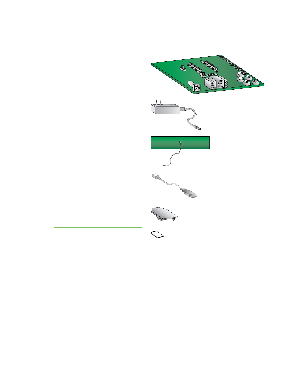
Identify the kit contents
The Developer's kit includes the following:
One XBIB-U-DEV board
One 12 V power supply
One cellular antenna with U.FL connector
One USB cable
One XBee Cellular Modem
Note The XBee Cellular Modem comes
attached to the board in ESDwrap.
One SIMcard
Digi XBee Cellular 3G Global Embedded Modem User Guide
18
Page 19
Get started with the XBee Cellular Modem Connect the hardware
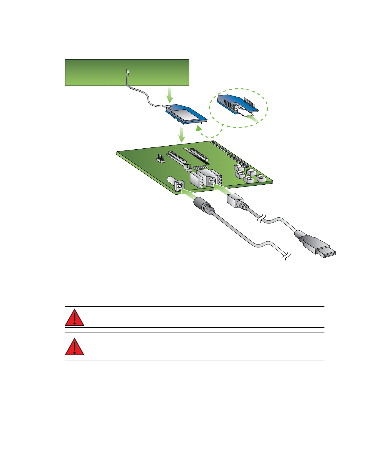
Connect the hardware
1. The XBee Cellular Modem should already be plugged into the XBIB-U-DEV board. For more
information about development boards, see Development boards.
2. The SIMcard should be already be inserted into the XBee Cellular Modem. If not, install the
SIMcard into the XBee Cellular Modem.
WARNING! Never insert or remove the SIM card while the device is powered!
WARNING! The development board power supply only supports 3G mode. It does not
support 2G mode.
3. Connect the antenna to the XBee Cellular Modem by aligning the U.FL connector carefully, then
firmly pressing straight down to seat the connector. You should hear a snap when the antenna
attaches correctly. U.FL is fragile and is not designed for multiple insertions, so exercise
caution when connecting or removing the antennas. We recommend using a U.FL removal tool.
4. Plug the 12 V power supply to the power jack on the development board.
5. Connect the USB cable from a PC to the USB port on the development board. The computer
searches for a driver, which can take a few minutes to install.
Digi XBee Cellular 3G Global Embedded Modem User Guide
19
Page 20
Get started with the XBee Cellular Modem Install and upgrade XCTU
Install and upgrade XCTU
XBee Configuration and Test Utility (XCTU) is a multi-platform program developed by Digi that enables
users to interact with Digi radio frequency (RF) devices through a graphical interface. The application
includes built-in tools that make it easy to set up, configure, and test Digi RF devices.
XCTU does not work directly over an SPI interface.
You can use XCTU to update the device firmware. Firmware is the program code stored in the device's
persistent memory that provides the control program for the device.
Note You cannot update the cellular component on a 3G device.
For instructions on downloading and using XCTU, see the XCTU User Guide.
Note If you are on a macOS computer and encounter problems installing XCTU, see Correct a macOS
Java error.
Step 1: Install and upgrade XCTU
You can use XCTU to update the device firmware.
1. To use XCTU, you may need to install FTDI Virtual COMport (VCP)drivers onto your computer.
Click here to download the drivers for your operating system.
2. Upgrade XCTU to the latest version. This step is required.
Step 2: Add a device to XCTU
You must add a device to XCTU before you can update the device's firmware or configure the device
from XCTU.
Add a device to XCTU
These instructions show you how to add the XBee to XCTU.
If XCTU does not find your serial port, see Cannot find the serial port for the device and Enable Virtual
COM port (VCP) on the driver.
1.
Launch XCTU .
Note XCTU's Update the radio module firmware dialog box may open and will not allow you
to continue until you click Update or Cancel on the dialog.
2. Click Help > Check for XCTUUpdates to ensure you are using the latest version of XCTU.
3.
Click the Discover radio modules button in the upper left side of the XCTU screen.
4. In the Discover radio devices dialog, select the serial ports where you want to look for XBee
modules, and click Next.
5. In the Set port parameters window, maintain the default values and click Finish.
6. As XCTU locates radio modules, they appear in the Discovering radio modules dialog box.
7. Select the device(s) you want to add and click Add selected devices.
If your module could not be found, XCTU displays the Could not find any radio module dialog
providing possible reasons why the module could not be added.
Digi XBee Cellular 3G Global Embedded Modem User Guide
20
Page 21
Get started with the XBee Cellular Modem Update the device firmware using XCTU
Update the device firmware using XCTU
You should use XCTU to update the device firmware on your XBee to the most recent version. This
ensures that you can take advantage of all the latest fixes and features.
Update the device firmware using XCTU.
Check for cellular registration and connection
The cellular network registration and address assignment must occur successfully. To verify the
network connection, you can view the LED on the development board or check the status of the
relevant commands in XCTU.
Registration can take several minutes.
Before you begin
n Make sure you have added the device to XCTU. See Add a device to XCTU.
n Make sure you are in an area with adequate cellular network reception.
n Verify that the antennas are connected properly to the device.
View LED action
The LED on the development board blinks when the XBee is registered to the cellular network; see
Associate LED functionality. If the LEDremains solid, registration has not occurred properly.
View commands in SCTU
1.
Launch XCTU .
2.
Click the Configuration working mode button.
3. Select a device from the Radio Modules list. XCTU displays the current firmware settings for
that device.
4. Verify the status of your network connection using the following commands:
n AI (Association Indication) reads 0 when the device successfully registers to the
cellular network and the LED is blinking. If it reads 23 it is connecting to the Internet; 22
means it is registering to the cellular network.
n MY (Module IP Address) should display a valid IPaddress. If it reads 0.0.0.0, it has not
registered yet.
Hints
n
To search for an ATcommand in XCTU, use the search box .
n
To read a command's value, click the Read button next to the command.
Digi XBee Cellular 3G Global Embedded Modem User Guide
21
Page 22

XBee connection examples
The following examples provide some additional scenarios you can try to get familiar with the XBee.
These examples are focused on inter-operating with a host processor to drive the XBee.
If you are interested in using the intelligence built into the XBee, see Get started with MicroPython.
Note Some carriers restrict your internet access. If access is restricted, running some of these
examples may not be possible. Check with your carrier provider to determine whether internet access
is restricted.
Connect to the Echo server 23
Connect to the ELIZA server 24
Connect to the Daytime server 25
Perform a (GET) HTTP request 27
Connect to a TCP/IP address 28
Debugging 29
Software libraries 29
Digi XBee Cellular 3G Global Embedded Modem User Guide
22
Page 23
XBee connection examples Connect to the Echo server
Connect to the Echo server
This server echoes back the messages you type.
Note For help with debugging, see Debugging.
The following table explains the AT commands that you use in this example.
At
command Value Description
IP (IP
Protocol)
TD
(Text
Delimiter)
DL
(Destination
Address)
DE
(Destination
Port)
1 Set the expected
transmission mode to
TCP communications.
D (0x0D)
52.43.121.77 The target IPaddress of
2329 (0x2329) The target port number of
The text delimiter to be
used for Transparent
mode, as an ASCII hex
code. No information is
sent until this character is
entered, unless the
maximum number of
characters has been
reached. Set to 0 to
disable text delimiter
checking. Set to D for a
carriage return.
the echo server.
the echo server.
To communicate with the Echo server:
1. Ensure that the device is set up correctly with the SIM card installed and the antennas
connected as described in Connect the hardware.
2. Open XCTU and Add a device to XCTU.
3.
Click the Configuration working mode button.
4. Select a device from the Radio Modules list. XCTU displays the current firmware settings for
that device.
5.
To switch to TCP communication, in the IP field, select 1 and click the Write button .
6. To enable the XBee to recognize carriage return as a message delimiter, in the TD field, type D
and click the Write button.
7. To enter the destination address of the echo server, in the DL field, type 52.43.121.77 and click
the Write button.
8. To enter the destination IP port number, in the DE field, type 2329 and click the Write button.
Digi XBee Cellular 3G Global Embedded Modem User Guide
23
Page 24
XBee connection examples Connect to the ELIZA server
Note XCTU does not follow the standard hexadecimal numbering convention. The leading 0x is
not needed in XCTU.
9.
Click the Consoles working mode button on the toolbar to open a serial console to the
device. For instructions on using the Console, see the AT console topic in the XCTU User Guide.
10.
Click the Open button to open a serial connection to the device.
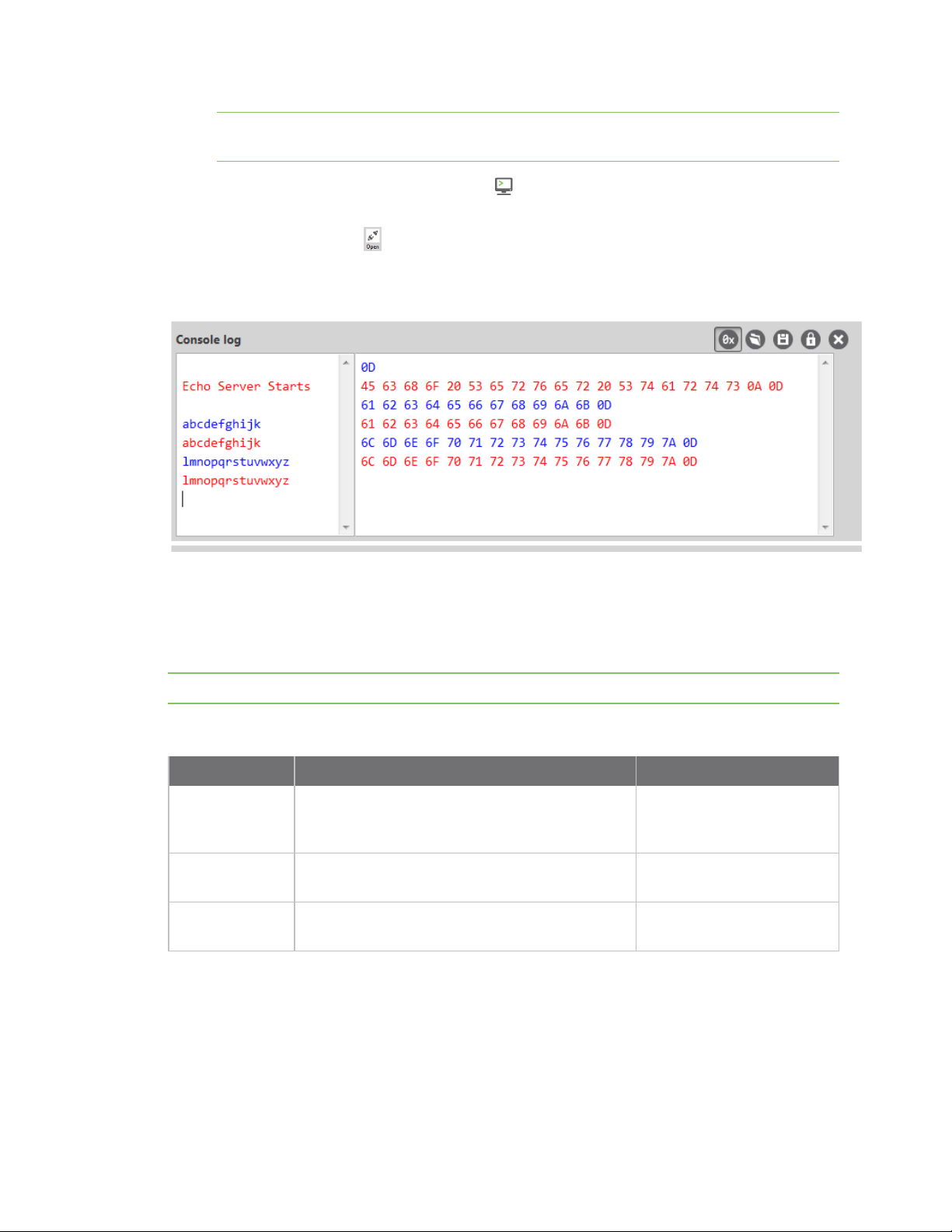
11. Click in the left pane of the Console log, then type in the Console to talk to the echo server.
The following screenshot provides an example of this chat.
Connect to the ELIZA server
You can use the XBee to chat with the ELIZA Therapist Bot. ELIZAis an artificial intelligence (AI) bot
that emulates a therapist and can perform simple conversations.
Note For help with debugging, see Debugging.
The following table explains the AT commands that you use in this example.
At command Value Description
IP (IP Protocol) 1 Set the expected
DL (Destination
Address)
DE (Destination
Port)
To communicate with the ELIZA Therapist Bot:
1. Ensure that the device is set up correctly with the SIM card installed and the antennas
connected as described in Connect the hardware.
2. Open XCTU and Add a device to XCTU.
52.43.121.77 The target IP address of the
2328 (0x2328) The target port number of
transmission mode to TCP
communications.
ELIZA server.
the ELIZA server.
Digi XBee Cellular 3G Global Embedded Modem User Guide
24
Page 25
XBee connection examples Connect to the Daytime server
3.
Click the Configuration working mode button.
4. Select a device from the Radio Modules list. XCTU displays the current firmware settings for
that device.
5.
To switch to TCP communication, in the IP field, select 1 and click the Write button .
6. To enter the destination address of the ELIZATherapist Bot, in the DL field, type 52.43.121.77
and click the Write button.
7. To enter the destination IP port number, in the DE field, type 2328 and click the Write button.
8.
Click the Consoles working mode button on the toolbar to open a serial console to the
device. For instructions on using the Console, see the AT console topic in the XCTU User Guide.
9.
Click the Open button to open a serial connection to the device.
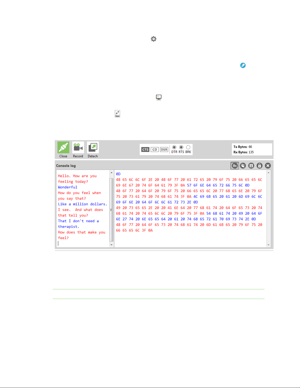
10. Click in the left pane of the Console log, then type in the Console to talk to the ELIZA Therapist
Bot. The following screenshot provides an example of this chat with the user's text in blue.
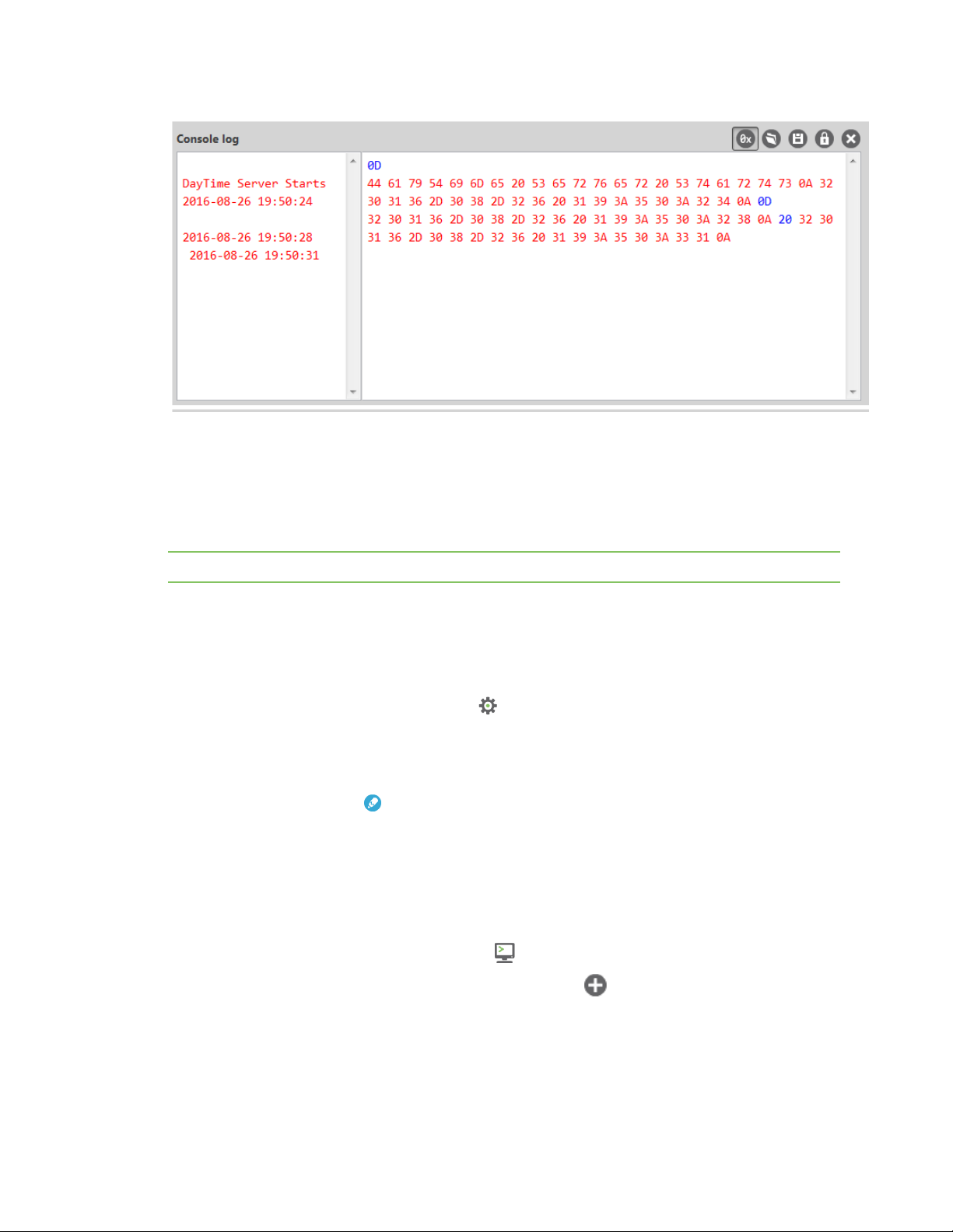
Connect to the Daytime server
The Daytime server reports the current Coordinated Universal Time (UTC) value responding to any
user input.
Note For help with debugging, see Debugging.
The following table explains the AT commands that you use in this example.
Digi XBee Cellular 3G Global Embedded Modem User Guide
25
Page 26
XBee connection examples Connect to the Daytime server
At command Value Description
IP (IP
Protocol)
DL
(Destination
Address)
DE
(Destination
Port)
TD (Text
Delimiter)
To communicate with the Daytime server:
1. Ensure that the device is set up correctly with the SIM card installed and the antennas
connected as described in Connect the hardware.
2. Open XCTU and Add a device to XCTU.
1 Set the expected transmission
mode to TCP communications.
52.43.121.77 The target IP of the Daytime
server.
232A (0x232A) The target port number of the
Daytime server.
0
The text delimiter to be used for
Transparent mode, as an ASCII
hex code. No information is sent
until this character is entered,
unless the maximum number of
characters has been reached. Set
to zero to disable text delimiter
checking.
3.
Click the Configuration working mode button.
4. Select a device from the Radio Modules list. XCTU displays the current firmware settings for
that device.
5.
To switch to TCP communication, in the IP field, select 1 and click the Write button .
6. To enter the destination address of the daytime server, in the DL field, type 52.43.121.77 and
click the Write button.
7. To enter the destination IP port number, in the DE field, type 232A and click the Write button.
8. To disable text delimiter checking, in the TD field, type 0 and click the Write button.
9.
Click the Consoles working mode button on the toolbar to open a serial console to the
device. For instructions on using the Console, see the AT console topic in the XCTU User Guide.
10.
Click the Open button to open a serial connection to the device.
11. Click in the left pane of the Console log, then type in the Console to query the Daytime server.
The following screenshot provides an example of this chat.
Digi XBee Cellular 3G Global Embedded Modem User Guide
26
Page 27
XBee connection examples Perform a (GET) HTTP request
Perform a (GET) HTTP request
You can use the XBee to perform a GET Hypertext Transfer Protocol (HTTP) request using XCTU. HTTP
is an application-layer protocol that runs over TCP. This example uses httpbin.org/ as the target
website that responds to the HTTP request.
Note For help with debugging, see Debugging.
To perform a GETrequest:
1. Ensure that the device is set up correctly with the SIM card installed and the antennas
connected as described in Connect the hardware.
2. Open XCTU and Add a device to XCTU.
3.
Click the Configuration working mode button.
4. Select a device from the Radio Modules list. XCTU displays the current firmware settings for
that device.
5. To enter the destination address of the target website, in the DL field, type httpbin.org and
click the Write button .
6. To enter the HTTP request port number, in the DE field, type 50 and click the Write button.
Hexadecimal 50 is 80 in decimal.
7. To switch to TCP communication, in the IP field, select 1 and click the Write button.
8. To move into Transparent mode, in the APfield, select 0 and click the Write button.
9. Wait for the AI (Association Indication) value to change to 0 (Connected to the Internet).
10.
Click the Consoles working mode button on the toolbar.
11.
From the AT console, click the Add new packet button in the Send packets dialog. The
Add new packet dialog appears.
12. Enter the name of the data packet.
13. Type the following data in the ASCII input tab:
GET /ip HTTP/1.1
Digi XBee Cellular 3G Global Embedded Modem User Guide
27
Page 28
XBee connection examples Connect to a TCP/IP address
Host: httpbin.org
14. Click the HEX input tab and add 0A (zero A) after each 0D (zero D), and add an additional 0D 0A
at the end of the message body. For example, copy and past the following text into the HEX
input tab:
47 45 54 20 2F 69 70 20 48 54 54 50 2F 31 2E 31 0D 0A 48 6F 73 74 3A 20 68 74 74 70 62 69 6E
2E 6F 72 67 0D 0A 0D 0A
Note The HTTP protocol requires an empty line (a line with nothing preceding the CRLF) to terminate
the request.
15. Click Add packet.
16.
Click the Open button .
17. Click Send selected packet.
18. A GETHTTP response from httpbin.org appears in the Console log.
Connect to a TCP/IP address
The XBee Cellular Modem can send and receive TCP messages while in Transparent mode; see
Transparent operating mode.
Note You can use this example as a template for sending and receiving data to or from any
TCP/IPserver.
Note For help with debugging, see Debugging.
The following table explains the AT commands that you use in this example.
Command Value Description
IP (IP
Protocol)
DL
(Destination
IPAddress)
DE
(Destination
Port)
To connect to a TCP/IP address:
1. Ensure that the device is set up correctly with the SIM card installed and the antennas
connected as described in Connect the hardware.
2. Open XCTU and Add a device to XCTU.
1 Set the expected transmission mode to TCPcommunication.
<Target
IPaddress>
<Target
portnumber>
The target IP address that you send and receive from. For example, a
data logging server’s IP address that you want to send
measurements to.
The target port number that the device sends the transmission to.
This is represented as a hexadecimal value.
3.
Click the Configuration working mode button.
4. Select a device from the Radio Modules list. XCTU displays the current firmware settings for
that device.
Digi XBee Cellular 3G Global Embedded Modem User Guide
28
Page 29

XBee connection examples Debugging
5.
In the IP field, select 1 and click the Write button .
6. In the DL field, type the <target IP address> and click the Write button. The target IP address
is the IPaddress that you send and receive from.
7. In the DE field, type the <target port number>, converted to hexadecimal, and click the Write
button.
8. Exit Command mode.
After exiting Command mode, any UART data sent to the device is sent to the destination IP address
and port number after the RO (Packetization Timeout) occurs.
Debugging
If you experience problems with the settings in the examples, you can load the default settings in
XCTU.
Note If you load the default settings, you will need to reapply any configuration settings that you have
previously made.
1.
On the Configuration toolbar, click the Default button to load the default values
established by the firmware, and click Yes to confirm.
2. Factory settings are loaded but not written to the device. To write them, click the Write button
on the toolbar.
Software libraries
One way to communicate with the XBee device is by using a software library. The libraries available
for use with the XBee Cellular Modem include:
n XBee Java library
n XBee Python library
n XBee ANSI C library
The XBee Java Library is a Java API. The package includes the XBee library, its source code and a
collection of samples that help you develop Java applications to communicate with your XBee devices.
The XBee Python Library is a Python API that dramatically reduces the time to market of XBee
projects developed in Python and facilitates the development of these types of applications, making it
an easy process.
The XBee ANSI C Library project is a collection of portable ANSI C code for communicating with the
devices in API mode.
Digi XBee Cellular 3G Global Embedded Modem User Guide
29
Page 30

Get started with Digi Remote Manager
Digi Remote Manager® is a cloud-based device and data management platform that you can use to
configure and update a device, and view and manage device data.
The sections below describe how to create a Remote Manager account, upgrading your device,
configure your device, and manage data in Remote Manager.
1. Create a Remote Manager account and add devices
2. To ensure that all Remote Manager features are available, you should upgrade your device to
the latest firmware. See Update the firmware from the Devices page in Remote Manager or
Update the firmware using web services in Remote Manager.
3. Configure your device in Remote Manager
To be able to configure your device in Remote Manager, the device must be connected to
Remote Manager. You can connect to and configure your device in Remote Manager using one
of the following methods:
o
Scheduled connection: In this method, you create a list of tasks that you want to
perform on the device, and then start the operation. This is the recommended method,
and is the best choice for low data usage. See Configure Remote Manager features by
scheduling tasks.
o
Always connected: This method can be used for initial configuration, or when you are
not concerned with low data usage. See Configure XBee settings within Remote
Manager.
4. Secure the connection between an XBee and Remote Manager with server authentication.
5. Manage data in Remote Manager
6. Remote Manager reference
Create a Remote Manager account and add devices
To be able to use Remote Manager, you must create a Remote Manager account and add your XBee
devices to the device list. You should also verify that the device is enabled to connect to Remote
Manager.
1. Create a Remote Manager account.
2. Add an XBee Cellular Modem to Remote Manager.
3. Verify the connection between a device and Remote Manager
Digi XBee Cellular 3G Global Embedded Modem User Guide
30
Page 31

Get started with Digi Remote Manager Create a Remote Manager account and add devices
Create a Remote Manager account
Digi Remote Manager is an on-demand service with no infrastructure requirements. Remote devices
and enterprise business applications connect to Remote Manager through standards-based web
services. This section describes how to configure and manage an XBee using Remote Manager. For
detailed information on using Remote Manager, refer to the Remote Manager User Guide, available via
the Documentation tab in Remote Manager.
Before you can manage an XBee with Remote Manager, you must create a Remote Manager account.
To create a Remote Manager account:
1. Go to https://www.digi.com/products/cloud/digi-remote-manager.
2. Click 30 DAYFREETRIAL/LOGIN.
3. Follow the online instructions to complete account registration. You can upgrade your
Developer account to a paid account at any time.
When you are ready to deploy multiple XBee Cellular Modems in the field, upgrade your account to
access additional Remote Manager features.
Add an XBee Cellular Modem to Remote Manager
Each XBee Cellular Modem must be added to the Remote Manager account inventory list.
Before adding an XBee to your Remote Manager account inventory, you need to determine the
International Mobile Equipment Identity (IMEI) number for the device. Use XCTUto view the IMEI
number by querying the IM parameter.
To add an XBee to your Remote Manager account inventory, follow these steps:
1. Log into Remote Manager.
2. Click Device Management > Devices.
3. Click Add Devices. The Add Devices dialog appears.
4. Select IMEI#, and type or paste the IMEI number of the XBee you want to add. The IM
(IMEI)command provides this number.
5. Click Add to add the device. The XBee is added to your inventory.
6. Click OK to close the Add Devices dialog and return to the Devices view.
Digi XBee Cellular 3G Global Embedded Modem User Guide
31
Page 32

Get started with Digi Remote Manager Configure Remote Manager features by scheduling tasks
Verify the connection between a device and Remote Manager
By default, the XBee is configured to enable communication with Remote Manager. The
communication between XBee and Remote Manager is achieved using periodic UDP operations.
You should verify the default settings to ensure that communcation will work as desired.
1.
Launch XCTU .
2. Verify that the MO command is set to 6, which is the default.
3. Configure the frequency of polls for Remote Manager activity using the DF command. The
default is 1440 minutes (24 hours).
4. Enable the SM/UDP feature in Remote Manager for each device. See Enable SM/UDP.
Configure Remote Manager features by scheduling tasks
Remote Manager provides tools to perform common management and maintenance tasks on your
XBee device. A Remote Manager task is a sequence of commands that can be performed on one or
more XBee Cellular devices. Tasks can then be assigned to a schedule. When a scheduled task is run it
becomes an active operation and can be monitored for status and completion.
Note You must upgrade your device to the latest firmware for all features to be available. See Update
the firmware.
Some typical examples of useful things that can be done with scheduled tasks include:
n Change configuration
n Update your MicroPython application and libraries to add features and capabilities
n Update your security certificates
n Perform a data service device request
n Send an SMS message to your device
Scheduled tasks can be created and performed through the following methods:
n Remote Manager Schedules user interface.
n Remote Manager API Explorer user interface
n Programming web service calls
Note For any of these methods to work properly, you must have SM/UDP enabled. See Enable
SM/UDP.
Overview: Create a schedule for a set of tasks
When using the most current firmware version, the XBee Cellular devices are designed to poll Remote
Manager once per day over the SM/UDP protocol to check for any active operations. In order to
perform a set of tasks, the device needs to be told to connect to Remote Manager, perform the
sequence of tasks, and then told to disconnect.
The following provides a template of how to create a schedule for an XBee to connect, perform a set
of tasks and then disconnect:
Digi XBee Cellular 3G Global Embedded Modem User Guide
32
Page 33

Get started with Digi Remote Manager Configure Remote Manager features by scheduling tasks
1. Make sure that SM/UDPis enabled. See Enable SM/UDP.
2. Log into Remote Manager.
3. Click Device Management > Schedules.
4. Click New Schedule. The New Schedule page displays.
Note The Steps to schedule a task wizard may display. Click the x in the upper left corner to
close the wizard. See Schedule walk-through feature in the Digi Remote Manager® User Guide for
more information.
5. In the Description field, enter a name for the schedule, such "Read Settings."
6. Add the following tasks:
a. Click SM/UDP > SM/UDP Request Connect. A task is added to the dialog.
b. Add other tasks as needed. For examples, refer to the Examples section.
c. Click Device > Disconnect. A task is added to the dialog.
7. Click Schedule in the lower right corner of the dialog to schedule the tasks to run. The
schedule screen displays.
Note You can also click Save as to save this schedule for future use.
8. Select the device(s) on which you want to run this schedule. You can add more than one device.
9. Click Run Now.
Examples
The examples in the following sections assume you are using the Digi Remote Manager Schedule
wizard. However, you should be aware that operations can be created and performed
programmatically via web service calls or via the API explorer. The XML web service calls provide more
options than are available in the GUI dashboard for some tasks.
Example: Read settings and state using Remote Manager
In order to configure devices you will need to know the structure of the XML for your XBee's settings.
The easiest way to obtain this is to perform a query_setting RCI request against your device.
Note You must upgrade your device to the latest firmware for all features to be available. See Update
the firmware.
Note To obtain the state of the device, you can perform the same operations in the example below,
but replace query_setting with query_state.
1. Log into Remote Manager.
2. Click Device Management > Schedules.
3. Click New Schedule. The New Schedule page displays.
Note The Steps to schedule a task wizard may display. Click the x in the upper left corner to
close the wizard. See Schedule walk-through feature in the Digi Remote Manager® User Guide for
more information.
Digi XBee Cellular 3G Global Embedded Modem User Guide
33
Page 34

Get started with Digi Remote Manager Configure Remote Manager features by scheduling tasks
4. In the Description field, enter a name for the schedule, such "Read Settings."
5. Add the following tasks:
a. Click SM/UDP > SM/UPD Request Connect. A task is added to the dialog.
b. Click Device > RCI Command. A task is added to the dialog.
Change the RCI command to the following:
<rci_request>
<query_setting/>
</rci_request>
c. Click Device > Disconnect. A task is added to the dialog.
6. Click Schedule in the lower right corner of the dialog to schedule the tasks to run. The
schedule screen displays.
Note You can also click Save as to save this schedule for future use.
7. Select the device(s) on which you want to run this schedule. You can add more than one device.
8. Click Run Now.
9. Click Device Management > Operations to view information about the operation. See
Operations in the Digi Remote Manager® User Guide for more information about this page.
After your operation completes you can click Response to view the XML for all of the settings that
your XBee reports. This XML structure has the same settings that you will use in the set_setting
command to configure your XBee as shown in this example: Example: Configure a device from Remote
Manager using XML.
Example: Configure a device from Remote Manager using XML
You can configure each XBee device from Remote Manager, using XML. The devices must be in the
Remote Manager inventory device list and be active.
Note You must upgrade your device to the latest firmware for all features to be available. See Update
the firmware.
In this configuration example, you are changing the device to poll four times a day instead of just once.
In this case, you should change the DF parameter to 360 minutes.
1. Log into Remote Manager.
2. Click Device Management > Schedules.
3. Click New Schedule. The New Schedule page displays.
Note The Steps to schedule a task wizard may display. Click the x in the upper left corner to
close the wizard. See Schedule walk-through feature in the Digi Remote Manager® User Guide for
more information.
4. In the Description field, enter a name for the schedule, such as "Configure Reporting
Frequency."
Digi XBee Cellular 3G Global Embedded Modem User Guide
34
Page 35

Get started with Digi Remote Manager Configure Remote Manager features by scheduling tasks
5. Add the following tasks:
a. Click SM/UDP > SM/UPD Request Connect. A task is added to the dialog.
b. Click Device > RCI Command. A task is added to the dialog.
Change the RCI command to the following:
<rci_request>
<set_setting>
<remote_manager>
<DF>360</DF>
</remote_manager>
</set_setting>
</rci_request>
c. Click Device > Disconnect. A task is added to the dialog.
6. Click Schedule in the lower right corner of the dialog to schedule the tasks to run. The
schedule screen displays.
Note You can also click Save as to save this schedule for future use.
7. Select the device(s) on which you want to run this schedule. You can add more than one device.
8. Click Run Now.
9. Click Device Management > Operations to view information about the operation. See
Operations in the Digi Remote Manager® User Guide for more information about this page.
Example: Schedule a task to update the device firmware using Remote Manager
You can use a scheduled task to update the XBee Cellular firmware. Since the device is configured by
default to poll Remote Manager once a day, you need to be able to set up a scheduled task to update
the device's firmware to take advantage of new features and fixes. To update the firmware to a new
version you will need to obtain the .ebin file for the new firmware from our support site. This file is one
of the files in the .zip (for example, XBXC-31011.zip) archive that you can download for the product.
Note You must upgrade your device to the latest firmware for all features to be available. See Update
the firmware.
To upgrade using a scheduled task perform the following steps:
1. Download the updated firmware file for your device from Digi's support site.
a. Go to the Digi XBee Cellular 3G support page.
b. Scroll down to the Firmware Updates section.
c. Locate and click XBee Cellular 3G AT&T Global Firmware to download the zip file.
d. Unzip the file.
2. Log into Remote Manager.
3. Make sure that you have enabled SM/UDP. See Enable SM/UDP.
Digi XBee Cellular 3G Global Embedded Modem User Guide
35
Page 36

Get started with Digi Remote Manager Configure Remote Manager features by scheduling tasks
4. Click Device Management > Schedules.
5. Click New Schedule. The New Schedule page displays.
Note The Steps to schedule a task wizard may display. Click the x in the upper left corner to
close the wizard. See Schedule walk-through feature in the Digi Remote Manager® User Guide for
more information.
6. In the Description field, enter a name for the schedule, such as "Update XBee Firmware."
7. Add the following tasks:
a. Click SM/UDP > SM/UDP Request Connect. A task is added to the dialog.
b. Click Device > Gateway Firmware Update.
c. Click Browse and select the .ebin file (for example, XBXC-11311.ebin) for the new firmware
to update.
d. Click Device > Disconnect. A task is added to the dialog.
8. Click Schedule in the lower right corner of the dialog to schedule the tasks to run. The
schedule screen displays.
Note You can also click Save as to save this schedule for future use.
9. Select the device(s) on which you want to run this schedule. You can add more than one device.
10. Click Run Now.
11. Click Device Management > Operations to view information about the operation. See
Operations in the Digi Remote Manager® User Guide for more information about this page.
Example: Update MicroPython from Remote Manager using XML
You can use the API Explorer in Remote Manager to create a schedule that enables you to update the
MicroPython application. In this example, you want to add FTP client capability to the MicroPython
application. You will need to add the library uftp.py and then update the main.py application.
This example is done following these steps: upload the MicroPython files to Remote Manager, create
an XML file with the tasks that you want to perform, upload the XML file, and then schedule an
operation to upload the files onto your device.
Note You must upgrade your device to the latest firmware for all features to be available. See Update
the firmware.
Step 1: Upload the MicroPython files
1. Log into Remote Manager.
2. Click Data Services > Data Files.
3. Upload the MicroPython application main.py file.
a. Click New Folder. The New Folder dialog displays.
b. In the Folder name field, enter a descriptive name, such as "MicroPython."
c. Click Create. The new file is added to the list of files.
d. Find the "MicroPython" folder in the folder list.
e. Click Upload Files. The Upload Files dialog displays.
Digi XBee Cellular 3G Global Embedded Modem User Guide
36
Page 37

Get started with Digi Remote Manager Configure Remote Manager features by scheduling tasks
f. Browse for the main.py file. Check with your system administrator for the location of the
application file.
g. Click OK.
4. Upload the MicroPython library uftp.py file.
a. Find the "MicroPython" folder in the folder list.
b. Click Upload Files. The Upload Files dialog displays.
c. Browse for the uftp.py file. The library uftp.py file is found on the GitHub repository:
https://github.com/digidotcom/xbee-micropython
d. Click OK.
Step 2: Create an XML file with the tasks that you want to perform
This XML file will contain a list of commands for the operation that you will schedule in Step 3.
Note The RCI commands to set_settings in the task may fail to execute because of disconnects after
changing the value for MO.
1. Open the editor of your choice.
2. Create a new file named updatemicropython.xml.
3. Copy the XML below and paste it into the new file.
4. Save the file.
<task>
<description>Update MicroPython</description>
<command>
<name>SM/UDP Request Connect</name>
<event>
<on_error>
<end_task/>
</on_error>
</event>
<sci>
<send_message reply="none" >
<sm_udp>
<request_connect/>
</sm_udp>
</send_message>
</sci>
</command>
<command>
<name>RCI Command</name>
<event>
<on_error>
<continue/>
</on_error>
</event>
<sci>
<send_message cache="false" allowOffline="true" >
<!-- Disable Python Auto-start and enable TCP connection for remainder of commands-->
<rci_request>
<set_setting>
<micropython>
<PS>0</PS>
</micropython>
Digi XBee Cellular 3G Global Embedded Modem User Guide
37
Page 38

Get started with Digi Remote Manager Configure Remote Manager features by scheduling tasks
<remote_manager>
<MO>7</MO>
</remote_manager>
</set_setting>
</rci_request>
</send_message>
</sci>
</command>
<command>
<!-- Reboot to stop MicroPython -->
<name>Reboot</name>
<event>
<on_error>
<continue/>
</on_error>
</event>
<sci>
<reboot allowOffline="true" waitForReconnect="true"/>
</sci>
</command>
<!-- Update MicroPython application-->
<command>
<name>Upload Files</name>
<event>
<on_error>
<continue/>
</on_error>
</event>
<sci>
<file_system allowOffline="true" >
<commands>
<put_file path="/flash/main.py">
<file>~/MicroPython/main.py</file>
</put_file>
</commands>
</file_system>
</sci>
</command>
<command>
<name>Upload Files</name>
<event>
<on_error>
<continue/>
</on_error>
</event>
<sci>
<file_system allowOffline="true" >
<commands>
<put_file path="/flash/lib/uftp.py">
<file>~/MicroPython/uftp.py</file>
</put_file>
</commands>
</file_system>
</sci>
</command>
<command>
<name>RCI Command</name>
<event>
<on_error>
<continue/>
Digi XBee Cellular 3G Global Embedded Modem User Guide
38
Page 39

Get started with Digi Remote Manager Configure Remote Manager features by scheduling tasks
</on_error>
</event>
<sci>
<send_message cache="false" allowOffline="true">
<!-- Enable Python Auto-start -->
<rci_request>
<set_setting>
<micropython>
<PS>1</PS>
</micropython>
<remote_manager>
<MO>6</MO>
</remote_manager>
</set_setting>
</rci_request>
</send_message>
</sci>
</command>
<!-- Reboot to start the program -->
<command>
<name>Reboot</name>
<event>
<on_error>
<end_task/>
</on_error>
</event>
<sci>
<reboot allowOffline="true" waitForReconnect="false"/>
</sci>
</command>
</task>
Step 3: Upload the XML to Remote Manager
In this step you will upload the file you just created (updatemicropython.xml) to Remote Manager.
1. Log into Remote Manager.
2. Click Data Services > Data Files.
3. Upload the XML file you just created: updatemicropython.xml
a. Find the "~/my_tasks" folder in the folder list.
b. Click Upload Files. The Upload Files dialog displays.
c. Browse for the updatemicropython.xml file.
d. Click OK.
Step 4: Schedule an operation to upload the files
1. Log into Remote Manager.
2. Click Documentation > API Explorer.
3. Click SCI Targets. The Select devices to be used in examples dialog appears.
a. From the Add Targets list box, search for the IMEI (device ID) of the device that you want
to update.
Digi XBee Cellular 3G Global Embedded Modem User Guide
39
Page 40

Get started with Digi Remote Manager Manage data in Remote Manager
b. Click Add. The device is added to the device list.
c. Click OK.
4. Click the Examples drop-down list button.
5. Click Scheduled Operation > Create immediate running schedule.
6. Update the XML to refer to the updatemicropython.xml file you created previously.
<!-- Runs immediately -->
<Schedule on="IMMEDIATE">
<targets>
<device id="00010000-00000000-03588320-70372440"/>
</targets>
<task path="~/my_tasks/updatemicropython.xml"/>
</Schedule>
7. Click Send to schedule the task.
8. Click Device Management > Operations to view information about the operation. See
Operations in the Digi Remote Manager® User Guide for more information about this page.
Manage data in Remote Manager
You can view and manage XBee data in Remote Manager.
You can also update your device firmware from Remote Manager. See Update the device firmware.
Review device status information from Remote Manager
You can view address, BLE, cellular, firmware, and I/O sampling status information for a XBee device in
Remote Manager. The device must be in the Remote Manager inventory device list and be active.
1. Set up a persistent connection to connect the device to Remote Manager using one of the
following methods:
n Remote Manager: A persistent connection can be set up in Remote Manager. This
option should be used when you have many deployed devices and no local access. See
Restore persistent connection to a remote XBee.
n XCTU: This option allows immediate access, and should be used when you have local
access, such as when using a development kit or in a lab environment.
2. Log into Remote Manager.
3. Click Device Management > Devices.
4. Select the device that you want to configure.
5. Click Properties in the toolbar. As an alternative, click Properties > Edit Device
Configuration. The configuration Home page appears.
6. Click Status in the toolbar to display the status sub-menus.
7. Click on the status group that has information you want to display. The status information is
related to ATcommands. For information about each ATcommand in the categories, click on
the appropriate link below.
Digi XBee Cellular 3G Global Embedded Modem User Guide
40
Page 41

Get started with Digi Remote Manager Manage data in Remote Manager
n Addressing
n Cellular
n Firmware Version/Information
n I/O
8. Click Home to return to the configuration Home page.
9. When all changes are complete, disconnect the device from Remote Manager.
Manage secure files in Remote Manager
You can interact with files on the XBee device from Remote Manager, using either the SCI (Server
command interface) or in the File Management view.
You can securely upload files by appending a hash sign (#) to the end of the file name. After the upload,
the hash sign (#) is not retained as part of the file name. For example, you could upload a file named
my-cert.crt appended with a hash sign (#): my-cert.crt#. After the upload is complete, the file is named
my-cert.crt.
Note Uploading secure files in Remote Manager has the same result as doing an ATFS XPUT locally.
See Secure files for more information.
SCI(Server command interface)
You can use the SCI (Server command interface) file_system command to securely upload a file.
For more information, see the file_system section in the Digi Remote Manager Programming Guide.
File Management view
You can upload and manage files in the Remote Manager File Management view.
1. Prepare the file that you want to upload.
a. Find the file on your hard drive.
b. Rename the file and append a hash sign (#) to the end of the file name.
2. Set up a persistent connection to connect the device to Remote Manager using one of the
following methods:
n Remote Manager: A persistent connection can be set up in Remote Manager. This
option should be used when you have many deployed devices and no local access. See
Restore persistent connection to a remote XBee.
n XCTU: This option allows immediate access, and should be used when you have local
access, such as when using a development kit or in a lab environment. See DO (Device
Options) and MO (Remote Manager Options). Both must be enabled.
3. Log into Remote Manager.
4. Click Device Management > Devices.
5. Select the device that you want to configure.
6. Click Properties in the toolbar. As an alternative, double-click on the device name. The
Properties page appears.
7. Click File Management. The File Management view appears.
Digi XBee Cellular 3G Global Embedded Modem User Guide
41
Page 42

Get started with Digi Remote Manager Remote Manager reference
8. Click the upload icon. The Upload File dialog appears.
a. Click Browse to browse for the file you want to upload. The selected file displays in the File
field. Make sure that the file name is appended by a hash sign (#).
b. Click OK. The uploaded file displays in the File Management view. Note that the file name
is no longer appended by a hash sign (#).
9. When all changes are complete, disconnect the device from Remote Manager.
Remote Manager reference
Enable SM/UDP
You can use the SM/UDP feature to leverage the very small data footprint of Remote Manager SM
protocol over UDP.
1. Log into Remote Manager.
2. Click Device Management > Devices.
3. Select the device that you want to configure.
4. Click More >SM/UDP > Configure. The SM/UDP dialog appears.
5. Verify that the Battery Operated Mode is not selected.
This mode is not supported with Remote Manager and if enabled, the connectivity between
XBee and Remote Manager may not work as expected.
6. Select SM/UDP Service Enabled to enable SM/UDP.
7. Click Save.
TCP connection
The TCP connection between an XBee and Remote Manager is dependent on the device's firmware
version. Options are to query Remote Manager once a day or to maintain a persistent TCP connection.
To determine which connection method is being used, refer to the version listed below.
Module Upgrade firmware version
XBee 3G 11311
n At or above the listed version: If your firmware version is at or above the listed version, your
device queries Remote Manager only once a day. The device connects to Remote Manager,
queries Remote Manager for updates and then receives updates. When the update is complete,
the device disconnects from Remote Manager.
If you upgrade to the new firmware version, it is recommended that you keep the polling
frequency low to reduce data usage. In order to upgrade firmware in the future, refer to
Example: Schedule a task to update the device firmware using Remote Manager.
Note If you wish to restore the persistent connection behavior that was the default in prior
firmware versions, see Restore persistent connection to a remote XBee.
Digi XBee Cellular 3G Global Embedded Modem User Guide
42
Page 43

Get started with Digi Remote Manager Remote Manager reference
n Below the listed version: If your firmware version is below the listed version, a persistent
TCPconnection is used by default. The device is continually connected to Remote Manager
using TCP.
Restore persistent connection to a remote XBee
The default connectivity to Remote Manager in the most recent firmware polls once a day using
SM/UDP, which means that your XBee will always appear in a disconnected state and will use
significantly less data.
If needed, you can restore the default connectivity to use the former behavior, where the device is
continually connected using TCP. To do this, you will need to set bit 0 of the MO setting. The suggested
value for MO is 7 to connect securely over TLS, or you can use 1 for no security, which is the legacy
value.
You can make the change using one of the following methods:
n Local access: If you have local access to the device you can use XCTU to change the MO setting
back to the former default value.
n Remote access: If you only have remote access to your XBee you can change the device to
maintain a persistent connection to Remote Manager. To do this you can set up a scheduled
operation in Remote Manger for your device, as shown below.
To set up a scheduled operation to maintain a persistent connection:
1. Log into Remote Manager.
2. Make sure that you have enabled SM/UDP. See Enable SM/UDP.
3. Click Device Management > Schedules.
4. Click New Schedule. The New Schedule page displays.
Note The Steps to schedule a task wizard may display. Click the x in the upper left corner to
close the wizard. See Schedule walk-through feature in the Digi Remote Manager® User Guide for
more information.
5. In the Description field, enter a name for the schedule, such as "Restore Persistent."
6. Add the following tasks:
a. Click SM/UDP > SM/UPD Request Connect. A task is added to the dialog.
b. Click Device > RCI Command. A task is added to the dialog.
Change the RCI command to the following:
<rci_request>
<set_setting>
<remote_manager>
<MO>7</MO>
</remote_manager>
</set_setting>
</rci_request>
7. Click Schedule in the lower right corner of the dialog to schedule the tasks to run. The
schedule screen displays.
Digi XBee Cellular 3G Global Embedded Modem User Guide
43
Page 44

Get started with Digi Remote Manager Remote Manager reference
Note You can also click Save as to save this schedule for future use. The XML for your task is
saved in the ~\my_tasks directory on Data Services > Data Files in Remote Manager.
8. Select the device(s) on which you want to run this schedule. You can add more than one device.
9. Click Run Now. Within the next 24 hours, which is the default polling period for querying
Remote Manager, your device will connect and will remain connected, as specified by the
change to the MO setting.
10. Click Device Management > Operations to view information about the operation. See
Operations in the Digi Remote Manager® User Guide for more information about this page.
Disconnect
The TCP connection remains open and periodic polling occurs until you manually disconnect the
TCPconnection. After you have disconnected the TCP connection, Remote Manager is no longer
updated.
You can disconnect the TCP connection using either of the following methods:
n From the Devices page in Remote Manager: See Disconnect a device in the Digi Remote
Manager® User Guide.
n Using web services in Remote Manager: See Request connect SM/UDP support in the Digi
Remote Manager® Programming Guide.
Configure XBee settings within Remote Manager
You can configure the device settings to use features with Remote Manager. For more information,
see Example: Read settings and state using Remote Manager.
Configure device settings in Remote Manager
You can configure each XBee device from Remote Manager. The devices must be in the Remote
Manager inventory device list and be active.
1. Set up a persistent connection to connect the device to Remote Manager using one of the
following methods:
n Remote Manager: A persistent connection can be set up in Remote Manager. This
option should be used when you have many deployed devices and no local access. See
Restore persistent connection to a remote XBee.
n XCTU: This option allows immediate access, and should be used when you have local
access, such as when using a development kit or in a lab environment. See DO (Device
Options) and MO (Remote Manager Options). Both must be enabled.
2. Log into Remote Manager.
3. Click Device Management > Devices.
4. Select the device that you want to configure.
5. Click Properties in the toolbar. As an alternative, click Properties > Edit Device
Configuration. The configuration Home page appears.
6. Click Config in the toolbar to display the settings sub-menus.
7. Click on the settings category that you want to configure. The settings in that category appear.
Digi XBee Cellular 3G Global Embedded Modem User Guide
44
Page 45

Get started with Digi Remote Manager Remote Manager reference
8. Makethe desired configuration changes. See AT commands for information about each setting
in the categories.
9. As you finish configuring in each setting category, click Apply to save the changes. If the
changes are valid, Remote Manager writes them to non-volatile memory and applies them.
10. When all changes are complete, disconnect the device from Remote Manager.
Configure Remote Manager keepalive interval
Managing the data usage and the keepalive interval is important if you have the MO (Remote Manager
Options) command bit 0 set to 1 or if you have enabled the Request connect feature in Remote
Manager.
Digi Remote Manager is enabled on the XBee by default and has a 60 second keepalive interval, which
can result in excessive cellular data usage, depending on your plan. The K1 and K2 commands can be
used to tune the keepalive interval. Your carrier will disconnect an inactive socket automatically if
there is no activity, so you need to tune this value based on your carrier’s disconnect timeout.
You can further reduce your data usage by periodically duty cycling your Remote Manager connection,
either from MicroPython or your host processor. For example, you could enable the Remote Manager
connection for 2 hours a day and then disable the connection for 22 hours. Your host processor or
MicroPython program would need to keep track of the time to ensure the time interval.
Digi XBee Cellular 3G Global Embedded Modem User Guide
45
Page 46

Examples: IOT protocols with transparent mode
The following examples provide some additional scenarios you can use to get familiar with the XBee.
If you are interested in using the intelligence built into the XBee, see Get started with MicroPython.
Get started with CoAP 47
Get started with MQTT 51
Digi XBee Cellular 3G Global Embedded Modem User Guide
46
Page 47

Examples: IOT protocols with transparent mode Get started with CoAP
Get started with CoAP
Constrained Application Protocol (CoAP) is based on UDP connection and consumes low power to
deliver similar functionality to HTTP. This guide contains information about sending GET, POST, PUT
and DELETE operations by using the Coap Protocol with XCTU and Python code working with the XBee
Cellular Modem and Coapthon library (Python 2.7 only).
The Internet Engineering Task Force describes CoAP as:
The protocol is designed for machine-to-machine (M2M) applications such as smart energy and
building automation. CoAP provides a request/response interaction model between application
endpoints, supports built-in discovery of services and resources, and includes key concepts of
the Web such as URIs and Internet media types. CoAP is designed to easily interface with HTTP
for integration with the Web while meeting specialized requirements such as multicast
support, very low overhead, and simplicity for constrained environments (source).
CoAP terms
When describing CoAP, we use the following terms:
Term Meaning
Method COAP's method action is similar to the HTTP method. This guide discusses the GET,
POST, PUT and DELETE methods. With these methods, the XBee Cellular Modem can
transport data and requests.
URI URI is a string of characters that identifies a resource served at the server.
Token Atoken is an identifier of a message. The client uses the token to verify if the received
message is the correct response to its query.
Payload The message payload is associated with the POST and PUT methods. It specifies the
data to be posted or put to the URI resource.
MessageID The message ID is also an identifier of a message. The client matches the message ID
between the response and query.
CoAP quick start example
The following diagram shows the message format for the CoAP protocol; see ISSN: 2070-1721 for
details:
This is an example GET request:
44 01 C4 09 74 65 73 74 B7 65 78 61 6D 70 6C 65
Digi XBee Cellular 3G Global Embedded Modem User Guide
47
Page 48
Examples: IOT protocols with transparent mode Get started with CoAP
The following table describes the fields in the GETrequest.
Field HEX Bits Meaning
Ver 44 01 Version 01, which is mandatory here.
T 00 Type 0: confirmable.
TKL 0100 Token length: 4.
Code 01 000 00001 Code: 0.01, which indicates the GET method.
Message ID C4 09 2 Bytes equal
to hex at left
Token 74 65 73 74 4 Bytes equal
to hex at left
Option delta B7 1011 Delta option: 11 indicates the option data is Uri-Path.
Optionlength 0111 Delta length: 7 indicates there are 7 bytes of data
Option value 65 78 61 6D
70 6C 65
7 Bytes equal
to hex at left
Message ID. The response message will have the
same ID. This can help out identification.
Token. The response message will have the same
token. This can help out identification.
following as a part of this delta option.
Example.
Configure the device
1. Ensure that the device is set up correctly with the SIM card installed and the antennas
connected as described in Connect the hardware.
2.
Open XCTU and click the Configuration working mode button.
3. Add the XBee Cellular Modem to XCTU; see Add a device to XCTU.
4. Select a device from the Radio Modules list. XCTU displays the current firmware settings for
that device.
5.
To switch to UDPcommunication, in the IP field, select 0 and click the Write button .
6. To set the target IP address that the XBee Cellular Modem will talk to, in the DL field type
52.43.121.77and click the Write button . A CoAP server is publicly available at address
52.43.121.77.
7. To set the XBee Cellular Modem to send data to port 5683 in decimal, in the DEfield, type 1633
and click the Write button.
8. To move into Transparent mode, in the APfield, select 0 and click the Write button.
9. Wait for the AI (Association Indication) value to change to 0 (Connected to the Internet). You
can click Read to get an update on the AI value.
Example: manually perform a CoAPrequest
Follow the steps in Configure the device prior to this example. This example performs the CoAP
GETrequest:
Digi XBee Cellular 3G Global Embedded Modem User Guide
48
Page 49

Examples: IOT protocols with transparent mode Get started with CoAP
n Method: GET
n URI: example
n Given message token: test
1.
Click the Consoles working mode button on the toolbar to add a customized packet.
2.
From the AT console, click the Add new packet button in the Send packets dialog. The
Add new packet dialog appears.
3. Click the HEX tab and type the name of the data packet: GET_EXAMPLE.
4. Copy and past the following text into the HEX input tab:
44 01 C4 09 74 65 73 74 B7 65 78 61 6D 70 6C 65
This is the CoAP protocol message decomposed by bytes to perform a GET request on an
example URI with a token test.
5. Click Add packet.
6.
Click the Open button .
7. Click Send selected packet. The message is sent to the public CoAP server configured in
Configure the device. A response appears in the Console log. Blue text is the query, red text is
the response.
The payload is Get to uri: example, which specifies that this is a successful CoAP GET to URI end
example, which was specified in the query.
Click the Close button to terminate the serial connection.
Example: use Python to generate a CoAP message
This example illustrates how the CoAP protocol can perform GET/POST/PUT/DELETE requests
similarly to the HTTP protocol and how to do this using the XBee Cellular Modem. In this example, the
XBee Cellular Modem talks to a CoAP Digi Server. You can use this client code to provide an abstract
wrapper to generate a CoAP message that commands the XBee Cellular Modem to talk to the remote
CoAP server.
Note It is crucial to configure the XBee Cellular Modem settings. See Configure the device and follow
the steps. You can target the IP address to a different CoAP public server.
1. Install Python 2.7. The Installation guide is located at: python.org/downloads/.
2. Download and install the CoAPthon library in the python environment from
pypi.python.org/pypi/CoAPthon.
3. Download these two .txt files: Coap.txt and CoapParser.txt. After you download them, open the
files in a text editor and save them as .py files.
4. In the folder that you place the Coap.py and CoapParser.py files, press Shift + right-click and
then click Open command window.
5. At the command prompt, type python Coap.py and press Enter to run the program.
6. Type the USB port number that the XBee Cellular Modem is connected to and press Enter. Only
the port number is required, so if the port is COM19, type 19.
Digi XBee Cellular 3G Global Embedded Modem User Guide
49
Page 50
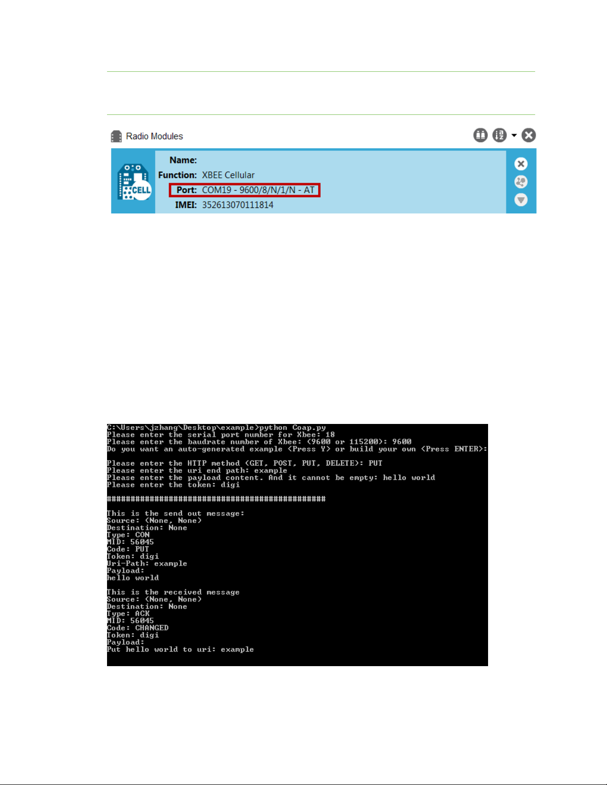
Examples: IOT protocols with transparent mode Get started with CoAP
Note If you do not know the port number, open XCTU and look at the XBee Cellular Modem in the
Radio Modules list. This view provides the port number and baud rate, as in the figure below where
the baud rate is 9600 b/s.
7. Type the baud rate and press Enter. You must match the device's current baud rate.
XCTUprovides the current baud rate in the BD Baud Rate field. In this example you would type
9600.
8. Press Y if you want an auto-generated example. Press Enter to build your own CoAP request.
9. If you press Y it generates a message with:
n Method: POST
n URI: example
n payload:hello world
n token: test
The send and receive message must match the same token and message id. Otherwise, the client reattempts the connection by sending out the request.
In the following figure, the payload contains the server response to the query. It shows the results for
when you press Enter rather than Y.
Digi XBee Cellular 3G Global Embedded Modem User Guide
50
Page 51

Examples: IOT protocols with transparent mode Get started with MQTT
Get started with MQTT
MQ Telemetry Transport (MQTT) is a messaging protocol that is ideal for the Internet of Things (IoT)
due to a light footprint and its use of the publish-subscribe model. In this model, a client connects to a
broker, a server machine responsible for receiving all messages, filtering them, and then sending
messages to the appropriate clients.
The first two MQTTexamples do not involve the XBee Cellular Modem. They demonstrate using the
MQTTlibraries because those libraries are required for Use MQTT over the XBee Cellular Modem with
a PC.
The examples in this guide assume:
n Some knowledge of Python.
n An integrated development environment (IDE)such as PyCharm, IDLE or something similar.
The examples require:
n An XBee Cellular Modem.
n A compatible development board.
n XCTU. See Install and upgrade XCTU.
n That you install Python on your computer. You can download Python from:
https://www.python.org/downloads/.
n That you install the pyserial and paho-mqtt libraries to the Python environment. If you use
Python 2, install these libraries from the command line with pip install pyserial and pip
install paho-mqtt. If you use Python 3, use pip3 install pyserial and pip3 install paho-mqtt.
n The full MQTT library source code, which includes examples and tests, which is available in the
paho-mqtt github repository at https://github.com/eclipse/paho.mqtt.python. To download this
repository you must have Git installed.
Example: MQTT connect
This example provides insight into the structure of packets in MQTT as well as the interaction
between the client and broker. MQTT uses different packets to accomplish tasks such as connecting,
subscribing, and publishing. You can use XCTU to perform a basic example of sending a broker a
connect packet and receiving the response from the server, without requiring any coding. This is a
good way to see how the client interacts with the broker and what a packet looks like. The following
table is an example connect packet:
Description Hex value
CONNECT packet fixed header
byte 1 Control packet type 0x10
byte 2 Remaining length 0x10
CONNECT packet variable header
Protocol name
byte 1 Length MSB (0) 0x00
Digi XBee Cellular 3G Global Embedded Modem User Guide
51
Page 52

Examples: IOT protocols with transparent mode Get started with MQTT
Description Hex value
byte 2 Length LSB (4) 0x04
byte 3 (M) 0x4D
byte 4 (Q) 0x51
byte 5 (T) 0x54
byte 6 (T) 0x54
Protocol level
byte 7 Level (4) 0x04
Connect flags
byte 8
Keep alive
byte 9 Keep Alive MSB (0) 0x00
byte 10 Keep Alive LSB (60) 0x3C
Client ID
byte 11 Length MSB (0) 0x00
byte 12 Length LSB (4) 0x04
byte 13 (D) 0x44
byte 14 (I) 0x49
byte 15 (G) 0x47
byte 16 (I) 0x49
The following table describes the fields in the packet:
Fieldname Description
ProtocolName The connect packet starts with the protocol name, which is MQTT. The length of
CONNECT flags byte, see the table below for the bits.
the protocol name (in bytes) is immediately before the name itself.
0x02
ProtocolLevel Refers to the version of MQTT in use, in this case a value of 4 indicates MQTT
version 3.1.1.
Connect Flags Indicate certain aspects of the packet. For simplicity, this example only sets the
Clean Session flag, which indicates to the client and broker to discard any previous
session and start a new one.
Keep Alive How often the client pings the broker to keep the connection alive; in this example
it is set to 60 seconds.
Digi XBee Cellular 3G Global Embedded Modem User Guide
52
Page 53

Examples: IOT protocols with transparent mode Get started with MQTT
Fieldname Description
Client ID The length of the ID (in bytes) precedes the ID itself. Each client connecting to a
broker must have a unique client ID. In the example, the ID is DIGI. When using the
Paho MQTT Python libraries, a random alphanumeric ID is generated if you do not
specify an ID.
The following table provides the CONNECT flag bits from byte 8, the CONNECT flags byte.
CONNECT Flag Bit(s) Bit 7 Bit 6 Bit 5 Bit 4 Bit 3 Bit 2 Bit 1 Bit 0
User name flag 0
Password flag 0
Will retain 0
Will QoS 0 0
Will flag 0
Clean session 1
Reserved 0
Send a connect packet
Now that you know what a connect packet looks like, you can send a connect packet to a broker and
view the response. Open XCTU and click the Configuration working mode button.
1. Ensure that the device is set up correctly with the SIM card installed and the antennas
connected as described in Connect the hardware.
2.
Open XCTU and click the Configuration working mode button.
3. Add the XBee Cellular Modem to XCTU. See Add a device to XCTU.
4. Select a device from the Radio Modules list. XCTU displays the current firmware settings for
that device.
5. In the APfield, set Transparent Mode to [0] if it is not already and click the Write button.
6. In the DL field, type the IP address or the fully qualified domain name of the broker you wish to
use. This example uses test.mosquitto.org.
7. In the DE field, type 75B and set the port that the broker uses. This example uses 75B, because
the default MQTT port is 1883 (0x75B).
8. Once you have entered the required values, click the Write button to write the changes to the
XBee Cellular Modem.
9.
Click the Consoles working mode button on the toolbar to open a serial console to the
device. For instructions on using the Console, see the AT console topic in the XCTU User Guide.
10.
Click the Open button to open a serial connection to the device.
11.
From the AT console, click the Add new packet button in the Send packets dialog. The
Add new packet dialog appears.
Digi XBee Cellular 3G Global Embedded Modem User Guide
53
Page 54
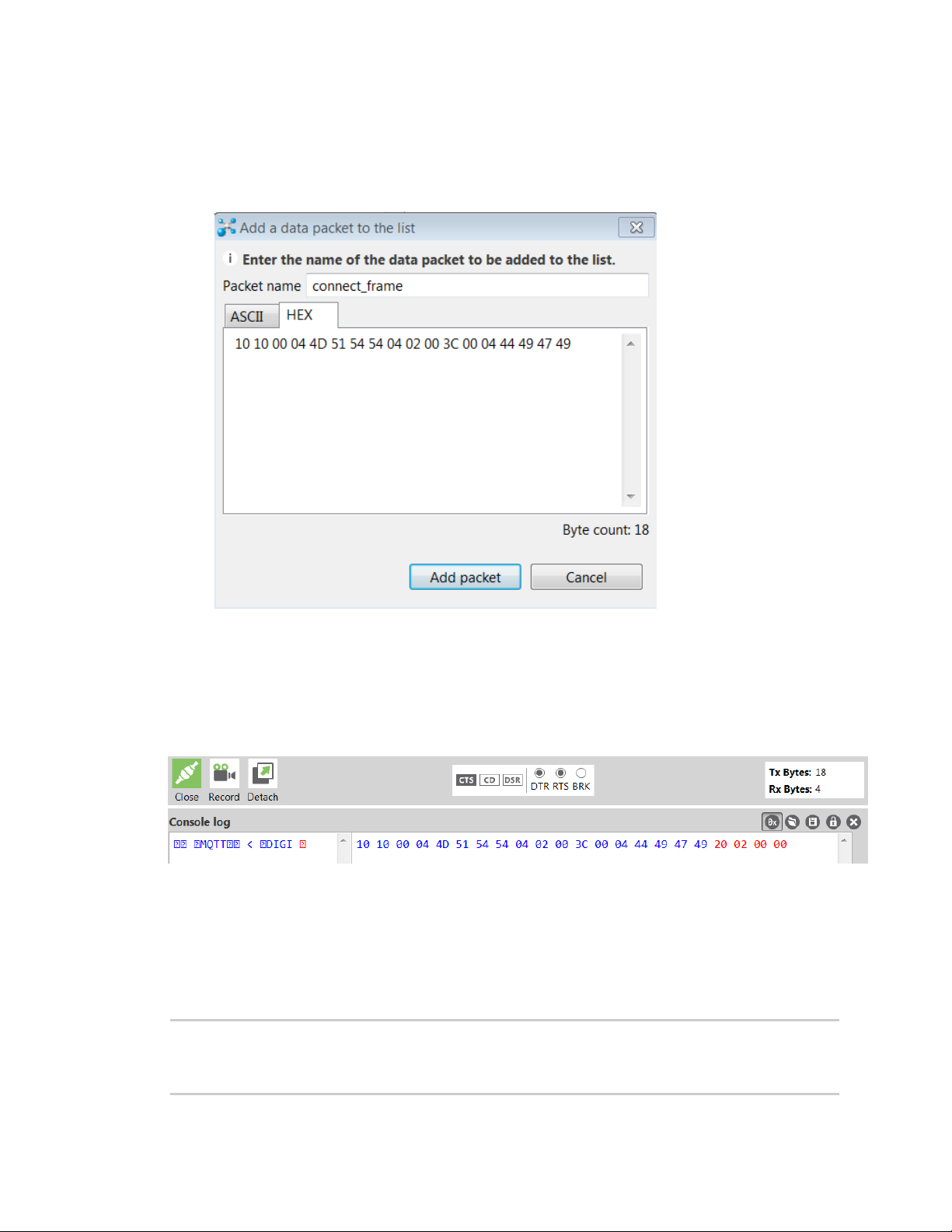
Examples: IOT protocols with transparent mode Get started with MQTT
12. Enter the name of the data packet. Name the packet connect_frame or something similar.
13. Click the HEX input tab and type the following (these values are the same values from the
table in Example: MQTT connect):
10 10 00 04 4D 51 54 54 04 02 00 3C 00 04 44 49 47 49
14. Click Add packet. The new packet appears in the Send packets list.
15. Click the packet in the Send packets list.
16. Click Send selected packet.
17. A CONNACK packet response from the broker appears in the Console log. This is a connection
acknowledgment; a successful response should look like this:
You can verify the response from the broker as a CONNACK by comparing it to the structure of a
CONNACK packet in the MQTT documentation, which is available at http://docs.oasis-
open.org/mqtt/mqtt/v3.1.1/os/mqtt-v3.1.1-os.html#_Toc398718081).
Example: send messages (publish) with MQTT
A basic Python example of a node publishing (sending) a message is:
mqttc = mqtt.Client("digitest") # Create instance of client with client ID
“digitest”
mqttc.connect("m2m.eclipse.org", 1883) # Connect to (broker, port,
keepalive-time)
Digi XBee Cellular 3G Global Embedded Modem User Guide
54
Page 55

Examples: IOT protocols with transparent mode Get started with MQTT
mqttc.loop_start() # Start networking daemon
mqttc.publish("digitest/test1", "Hello, World!") # Publish message to
“digitest /test1” topic
mqttc.loop_stop() # Kill networking daemon
Note You can easily copy and paste code from the online version of this guide. Use caution with the
PDF version, as it may not maintain essential indentations.
This example imports the MQTT library, allowing you to use the MQTT protocol via APIs in the library,
such as the connect(), subscribe(), and publish() methods.
The second line creates an instance of the client, named mqttc. The client ID is the argument you
passed in: digitest (this is optional).
In line 3, the client connects to a public broker, in this case m2m.eclipse.org, on port 1883 (the default
MQTT port, or 8883 for MQTT over TLS). There are many publicly available brokers available, you can
find a list of them here: https://github.com/mqtt/mqtt.github.io/wiki/brokers.
Line 4 starts the networking daemon with client.loop_start() to handle the background
network/data tasks.
Finally, the client publishes its message Hello, World! to the broker under the topic
digitest/backlog/test1. Any nodes (devices, phones, computers, even microcontrollers) subscribed to
that same topic on the same broker receive the message.
Once no more messages need to be published, the last line stops the network daemon with
client.loop_stop().
Example: receive messages (subscribe) with MQTT
This example describes how a client would receive messages from within a specific topic on the
broker:
import paho.mqtt.client as mqtt
def on_connect(client, userdata, flags, rc): # The callback for when the
client connects to the broker
print("Connected with result code {0}".format(str(rc))) # Print result
of connection attempt
client.subscribe("digitest/test1") # Subscribe to the topic
“digitest/test1”, receive any messages published on it
def on_message(client, userdata, msg): # The callback for when a PUBLISH
message is received from the server.
print("Message received-> " + msg.topic + " " + str(msg.payload)) #
Print a received msg
client = mqtt.Client("digi_mqtt_test") # Create instance of client with
client ID “digi_mqtt_test”
client.on_connect = on_connect # Define callback function for successful
connection
client.on_message = on_message # Define callback function for receipt of a
message
# client.connect("m2m.eclipse.org", 1883, 60) # Connect to (broker, port,
keepalive-time)
client.connect('127.0.0.1', 17300)
Digi XBee Cellular 3G Global Embedded Modem User Guide
55
Page 56

Examples: IOT protocols with transparent mode Get started with MQTT
client.loop_forever() # Start networking daemon
Note You can easily copy and paste code from the online version of this guide. Use caution with the
PDF version, as it may not maintain essential indentations.
The first line imports the library functions for MQTT.
The functions on_connect and on_message are callback functions which are automatically called by
the client upon connection to the broker and upon receiving a message, respectively.
The on_connect function prints the result of the connection attempt, and performs the subscription.
It is wise to do this in the callback function as it guarantees the attempt to subscribe happens only
after the client is connected to the broker.
The on_message function prints the received message when it comes in, as well as the topic it was
published under.
In the body of the code, we:
n Instantiate a client object with the client ID digi_mqtt_test.
n Define the callback functions to use upon connection and upon message receipt.
n Connect to an MQTT broker at m2m.eclipse.org, on port 1883 (the default MQTT port, or 8883
for MQTT over TLS) with a keepalive of 60 seconds (this is how often the client pings the broker
to keep the connection alive).
The last line starts a network daemon that runs in the background and handles data transactions and
messages, as well as keeping the socket open, until the script ends.
Use MQTT over the XBee Cellular Modem with a PC
To use this MQTT library over an XBee Cellular Modem, you need a basic proxy that transfers a payload
received via the MQTT client’s socket to the serial or COM port that the XBee Cellular Modem is active
on, as well as the reverse; transfer of a payload received on the XBee Cellular Modem’s serial or COM
port to the socket of the MQTT client. This is simplest with the XBee Cellular Modem in Transparent
mode, as it does not require code to parse or create API frames, and not using API frames means
there is no need for them to be queued for processing.
1. To put the XBee Cellular Modem in Transparent mode, set AP to 0.
2. Set DL to the IP address of the broker you want to use.
3. Set DE to the port to use, the default is 1883 (0x75B). This sets the XBee Cellular Modem to
communicate directly with the broker, and can be performed in XCTU as described in Example:
MQTT connect.
4. You can make the proxy with a dual-threaded Python script, a simple version follows:
import threading
import serial
import socket
def setup():
"""
This function sets up the variables needed, including the serial port,
and it's speed/port settings, listening socket, and localhost adddress.
"""
Digi XBee Cellular 3G Global Embedded Modem User Guide
56
Page 57

Examples: IOT protocols with transparent mode Get started with MQTT
global clisock, cliaddr, svrsock, ser
# Change this to the COM port your XBee Cellular module is using. On
# Linux, this will be /dev/ttyUSB#
comport = 'COM44'
# This is the default serial communication speed of the XBee Cellular
# module
comspeed = 115200
buffer_size = 4096 # Default receive size in bytes
debug_on = 0 # Enables printing of debug messages
toval = None # Timeout value for serial port below
# Serial port object for XBCell modem
ser = serial.Serial(comport,comspeed,timeout=toval)
# Listening socket (accepts incoming connection)
svrsock = socket.socket(socket.AF_INET,socket.SOCK_STREAM)
# Allow address reuse on socket (eliminates some restart errors)
svrsock.setsockopt(socket.SOL_SOCKET, socket.SO_REUSEADDR, 1)
clisock = None
cliaddr = None # These are first defined before thread creation
addrtuple = ('127.0.0.1', 17300) # Address tuple for localhost
# Binds server socket to localhost (allows client program connection)
svrsock.bind(addrtuple)
svrsock.listen(1) # Allow (1) connection
def ComReaderThread():
"""
This thread listens on the defined serial port object ('ser') for data
from the modem, and upon receipt, sends it out to the client over the
client socket ('clisock').
"""
global clisock
while (1):
resp = ser.read() ## Read any available data from serial port
print("Received {} bytes from modem.".format(len(resp)))
clisock.sendall(resp) # Send RXd data out on client socket
print("Sent {} byte payload out socket to client.".format(len
(resp)))
def SockReaderThread():
"""
This thread listens to the MQTT client's socket and upon receiving a
payload, it sends this data out on the defined serial port ('ser') to
the
modem for transmission.
"""
global clisock
while (1):
data = clisock.recv(4096) # RX data from client socket
# If the RECV call returns 0 bytes, the socket has closed
if (len(data) == 0):
print("ERROR - socket has closed. Exiting socket reader
thread.")
return 1 # Exit the thread to avoid a loop of 0-byte receptions
else:
print("Received {} bytes from client via socket.".format(len
(data)))
Digi XBee Cellular 3G Global Embedded Modem User Guide
57
Page 58

Examples: IOT protocols with transparent mode Get started with MQTT
print("Sending payload to modem...")
bytes_wr = ser.write(data) # Write payload to modem via
UART/serial
print("Wrote {} bytes to modem".format(bytes_wr))
def main():
setup() # Setup the serial port and socket
global clisock, svrsock
if (not clisock): # Accept a connection on 'svrsock' to open 'clisock'
print("Awaiting ACCEPT on server sock...")
(clisock,cliaddr) = svrsock.accept() # Accept an incoming
connection
print("Connection accepted on socket")
# Make thread for ComReader
comthread = threading.Thread(target=ComReaderThread)
comthread.start() # Start the thread
# Make thread for SockReader
sockthread = threading.Thread(target=SockReaderThread)
sockthread.start() # Start the thread
main()
Note This script is a general TCP-UART proxy, and can be used for other applications or scripts that
use the TCP protocol. Its functionality is not limited to MQTT.
Note You can easily copy and paste code from the online version of this guide. Use caution with the
PDF version, as it may not maintain essential indentations.
This proxy script waits for an incoming connection on localhost (127.0.0.1), on port 17300. After
accepting a connection, and creating a socket for that connection (clisock), it creates two threads,
one that reads the serial or COM port that the XBee Cellular Modem is connected to, and one that
reads the socket (clisock), that the MQTT client is connected to.
With:
n The proxy script running
n The MQTT client connected to the proxy script via localhost (127.0.0.1)
n The XBee Cellular Modem connected to the machine via USB and properly powered
n AP, DL, and DE set correctly
the proxy acts as an intermediary between the MQTT client and the XBee Cellular Modem, allowing
the MQTT client to use the data connection provided by the device.
Think of the proxy script as a translator between the MQTT client and the XBee Cellular Modem. The
following figure shows the basic operation.
Digi XBee Cellular 3G Global Embedded Modem User Guide
58
Page 59

Examples: IOT protocols with transparent mode Get started with MQTT
The thread that reads the serial port forwards any data received onward to the client socket, and the
thread reading the client socket forwards any data received onward to the serial port. This is
represented in the figure above.
The proxy script needs to be running before running an MQTT publish or subscribe script.
1. With the proxy script running, run the subscribe example from Example: receive messages
(subscribe) with MQTT, but change the connect line from client.connect("m2m.eclipse.org",
1883, 60) to client.connect("127.0.0.1", port=17300, keepalive=20). This connects the
MQTT client to the proxy script, which in turn connects to a broker via the XBee Cellular
Modem’s internet connection.
2. Run the publish example from Example: send messages (publish) with MQTT in a third Python
instance (while the publish script is running you will have three Python scripts running at the
same time).
The publish script runs over your computer’s normal Internet connection, and does not use the XBee
Cellular Modem. You are able to see your published message appear in the subscribe script’s output
once it is received from the broker via the XBee Cellular Modem. If you watch the output of the proxy
script during this process you can see the receptions and transmissions taking place.
The proxy script must be running before you run the subscribe and publish scripts. If you stop the
subscribe script, the socket closes, and the proxy script shows an error. If you try to start the proxy
script after starting the subscribe script, you may also see a socket error. To avoid these errors, it is
best to start the scripts in the correct order: proxy, then subscribe, then publish.
Digi XBee Cellular 3G Global Embedded Modem User Guide
59
Page 60

Get started with MicroPython
This section provides an overview and simple examples of how to use MicroPython with the XBee
Cellular Modem. You can use MicroPython to enhance the intelligence of the XBee to enable you to do
edge-computing by adding business logic in MicroPython, rather than using external components.
Note For in-depth information and more complex code examples, refer to the Digi MicroPython
Programming Guide.
About MicroPython 61
MicroPython on the XBee Cellular Modem 61
Use XCTU to enter the MicroPython environment 61
Use the MicroPython Terminal in XCTU 62
Example: hello world 62
Example: turn on an LED 62
Example: debug the secondary UART 63
Exit MicroPython mode 64
Other terminal programs 64
Use picocom in Linux 66
Digi XBee Cellular 3G Global Embedded Modem User Guide
60
Page 61

Get started with MicroPython About MicroPython
About MicroPython
MicroPython is an open-source programming language based on Python 3, with much of the same
syntax and functionality, but modified to fit on small devices with limited hardware resources, such as
microcontrollers, or in this case, a cellular modem.
Why use MicroPython
MicroPython enables on-board intelligence for simple sensor or actuator applications using digital and
analog I/O. MicroPython can help manage battery life. Cryptic readings can be transformed into useful
data, excess transmissions can be intelligently filtered out, modern sensors and actuators can be
employed directly, and logic can glue inputs and outputs together in an intelligent way.
For more information about MicroPython, see www.micropython.org.
For more information about Python, see www.python.org.
MicroPython on the XBee Cellular Modem
The XBee Cellular Modem has MicroPython running on the device itself. You can access a MicroPython
prompt from the XBee Cellular Modem when you install it in an appropriate development board (XBDB
or XBIB), and connect it to a computer via a USB cable.
Note MicroPython does not work with SPI.
The examples in this guide assume:
n You have XCTU on your computer. See Install and upgrade XCTU.
n You have a terminal program installed on your computer. We recommend using the Use the
MicroPython Terminal in XCTU. This requires XCTU 6.3.7 or higher.
n You have an XBee Cellular Modem installed in an appropriate development board, such as an
XBIB-U-DEV.
Note Most examples in this guide require the XBIB-U-DEV board.
n The XBee Cellular Modem is connected to the computer via a USB cable and XCTU recognizes
it.
n The board is powered by an appropriate power supply, 12 VDC and at least 1.1 A.
Use XCTU to enter the MicroPython environment
To use the XBee Cellular Modem in the MicroPython environment:
1. Use XCTU to add the device(s); see Install and upgrade XCTU and Add a device to XCTU.
2. The XBee Cellular Modem appears as a box in the Radio Modules information panel. Each
module displays identifying information about itself.
3. Click this box to select the device and load its current settings.
4. Set the device's baud rate to 115200 b/s, in the BD field select 115200 [7] or higher and click
the Write button . We recommend using flow control to avoid data loss, especially when
pasting large amounts of code/text.
Digi XBee Cellular 3G Global Embedded Modem User Guide
61
Page 62

Get started with MicroPython Use the MicroPython Terminal in XCTU
5. Put the XBee Cellular Modem into MicroPython mode, in the APfield select MicroPython REPL
[4] and click the Write button .
6. Note what COM port(s) the XBee Cellular Modem is using, because you will need this
information when you use terminal communication. The Radio Modules information panel lists
the COM port in use.
Use the MicroPython Terminal in XCTU
You can use the MicroPython Terminal to communicate with the XBee Cellular Modem when it is in
MicroPython mode.1This requires XCTU 6.3.7 or higher. To enter MicroPython mode, follow the steps
in Use XCTU to enter the MicroPython environment. To use the MicroPython Terminal:
1.
Click the Tools drop-down menu and select MicroPython Terminal. The terminal opens.
2. Click Open. If you have not already added devices to XCTU:
a. In the Select the Serial/USB port area, click the COM port that the device uses.
b. Verify that the baud rate and other settings are correct.
3.
Click OK. The Open icon changes to Close , indicating that the device is properly connected.
4. Press Ctrl+B to get the MicroPython version banner and prompt.
You can now type or paste MicroPython commands at the >>> prompt.
Troubleshooting
If you receive No such port: 'Port is already in use by other applications.' in the MicroPython
Terminal close any other console sessions open inside XCTU and close any other serial terminal
programs connected to the device, then retry the MicroPython connection in XCTU.
If the device seems unresponsive, try pressing Ctrl+C to end any running programs.
You can use the +++ escape sequence and look for an OK for confirmation that you have the correct
baud rate.
Example: hello world
Before you begin, you must have previously added a device in XCTU. See Add a device to XCTU.
1. At the MicroPython >>> prompt, type the Python command: print("Hello, World!")
2. Press Enter to execute the command. The terminal echos back Hello, World!.
Example: turn on an LED
1. Note the DS4 LED on the XBIB board. The following image highlights it in a red box. The LED is
normally off.
1
See Other terminal programs if you do not use the MicroPython Terminal in XCTU.
Digi XBee Cellular 3G Global Embedded Modem User Guide
62
Page 63

Get started with MicroPython Example: debug the secondary UART
2. At the MicroPython >>> prompt, type the commands below, pressing Enter after each one.
After entering the last line of code, the LED illuminates. Anything after a # symbol is a
comment, and you do not need to type it.
Note You can easily copy and paste code from the online version of this guide. Use caution with the
PDF version, as it may not maintain essential indentations.
import machine
from machine import Pin
led = Pin("D4", Pin.OUT, value=0) # Makes a pin object set to output 0.
# One might expect 0 to mean OFF and 1 to mean ON, and this is normally the
case.
# But the LED we are turning on and off is setup as what is# known as
"active low".
# This means setting the pin to 0 allows current to flow through the LED and
then through the pin, to ground.
3. To turn it off, type the following and press Enter:
led.value(1)
You have successfully controlled an LED on the board using basic I/O.
Example: debug the secondary UART
This sample code is handy for debugging the secondary UART. It simply relays data between the
primary and secondary UARTs.
Digi XBee Cellular 3G Global Embedded Modem User Guide
63
Page 64
Get started with MicroPython Exit MicroPython mode
from machine import UART
import sys, time
def uart_init():
u = UART(1)
u.write('Testing from XBee\n')
return u
def uart_relay(u):
while True:
uart_data = u.read(-1)
if uart_data:
sys.stdout.buffer.write(uart_data)
stdin_data = sys.stdin.buffer.read(-1)
if stdin_data:
u.write(stdin_data)
time.sleep_ms(5)
u = uart_init()
uart_relay(u)
You only need to call uart_init() once.
Call uart_relay() to pass data between the UARTs.
Send Ctrl-C to exit relay mode.
When done, call u.close() to close the secondary UART.
Exit MicroPython mode
To exit MicroPython mode:
1.
In the XCTU MicroPython Terminal, click the green Close button .
2. Click Close at the bottom of the terminal to exit the terminal.
3.
In XCTU's Configuration working mode , change AP API Enable to another mode and click
the Write button . We recommend changing to Transparent mode [0], as most of the
examples use this mode.
Other terminal programs
If you do not use the MicroPython Terminal in XCTU, you can use other terminal programs to
communicate with the XBee Cellular Modem. If you use Microsoft Windows, follow the instructions for
Tera Term, if you use Linux, follow the instructions for picocom. To download these programs:
n Tera Term for Windows; see https://ttssh2.osdn.jp/index.html.en.
n Picocom for Linux; see https://developer.ridgerun.com/wiki/index.php/Setting_up_Picocom_-_
Ubuntu and for the source code and in-depth information https://github.com/npatefault/picocom.
Digi XBee Cellular 3G Global Embedded Modem User Guide
64
Page 65

Get started with MicroPython Other terminal programs
Tera Term for Windows
With the XBee Cellular Modem in MicroPython mode (AP = 4), you can access the MicroPython prompt
using a terminal.
1. Open Tera Term. The Tera Term: New connection window appears.
2. Click the Serial radio button to select a serial connection.
3. From the Port: drop-down menu, select the COM port that the XBee Cellular Modem is
connected to.
4. Click OK. The COMxx - Tera Term VT terminal window appears and Tera Term attempts to
connect to the device at a baud rate of 9600 b/s. The terminal will not allow communication
with the device since the baud rate setting is incorrect. You must change this rate as it was
previously set to 115200 b/s.
5. Click Setup and Serial Port. The Tera Term: Serial port setup window appears.
6. In the Tera Term: Serial port setup window, set the parameters to the following values:
n Port: Shows the port that the XBee Cellular Modem is connected on.
n Baud rate:115200
n Data: 8 bit
n Parity: none
n Stop: 1 bit
n Flow control: hardware
n Transmit delay: N/A
7. Click OK to apply the changes to the serial port settings. The settings should go into effect
right away.
8. To verify that local echo is not enabled and that extra line-feeds are not enabled:
a. In Tera Term, click Setup and select Terminal.
b. In the New-line area of the Tera Term: Serial port setup window, click the Receive drop-
down menu and select CR if it does not already show that value.
c. Make sure the Local echo box is not checked.
9. Click OK.
10. Press Ctrl+B to get the MicroPython version banner and prompt.
Digi XBee Cellular 3G Global Embedded Modem User Guide
65
Page 66
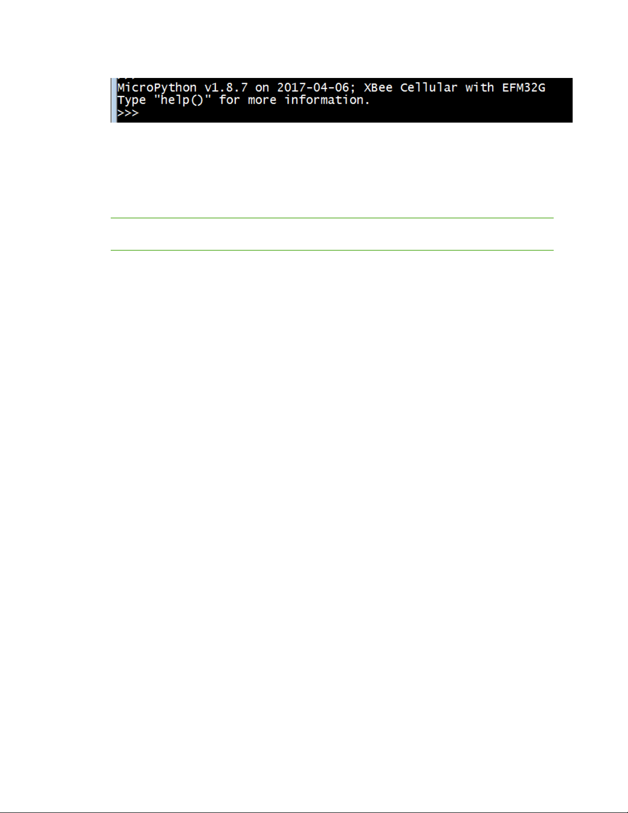
Get started with MicroPython Use picocom in Linux
Now you can type MicroPython commands at the >>> prompt.
Use picocom in Linux
With the XBee Cellular Modem in MicroPython mode (AP = 4), you can access the MicroPython prompt
using a terminal.
Note The user must have read and write permission for the serial port the XBee Cellular Modem is
connected to in order to communicate with the device.
1. Open a terminal in Linux and type picocom -b 115200 /dev/ttyUSB0. This assumes you have
no other USB-to-serial devices attached to the system.
2. Press Ctrl+B to get the MicroPython version banner and prompt. You can also press Enter to
bring up the prompt.
If you do have other USB-to-serial devices attached:
1. Before attaching the XBee Cellular Modem, check the directory /dev/ for any devices named
ttyUSBx, where x is a number. An easy way to list these is to type: ls /dev/ttyUSB*. This
produces a list of any device with a name that starts with ttyUSB.
2. Take note of the devices present with that name, and then connect the XBee Cellular Modem.
3. Check the directory again and you should see one additional device, which is the XBee Cellular
Modem.
4. In this case, replace /dev/ttyUSB0 at the top with /dev/ttyUSB<number>, where <number>
is the new number that appeared.
5. It should connect and show Terminal ready.
Digi XBee Cellular 3G Global Embedded Modem User Guide
66
Page 67
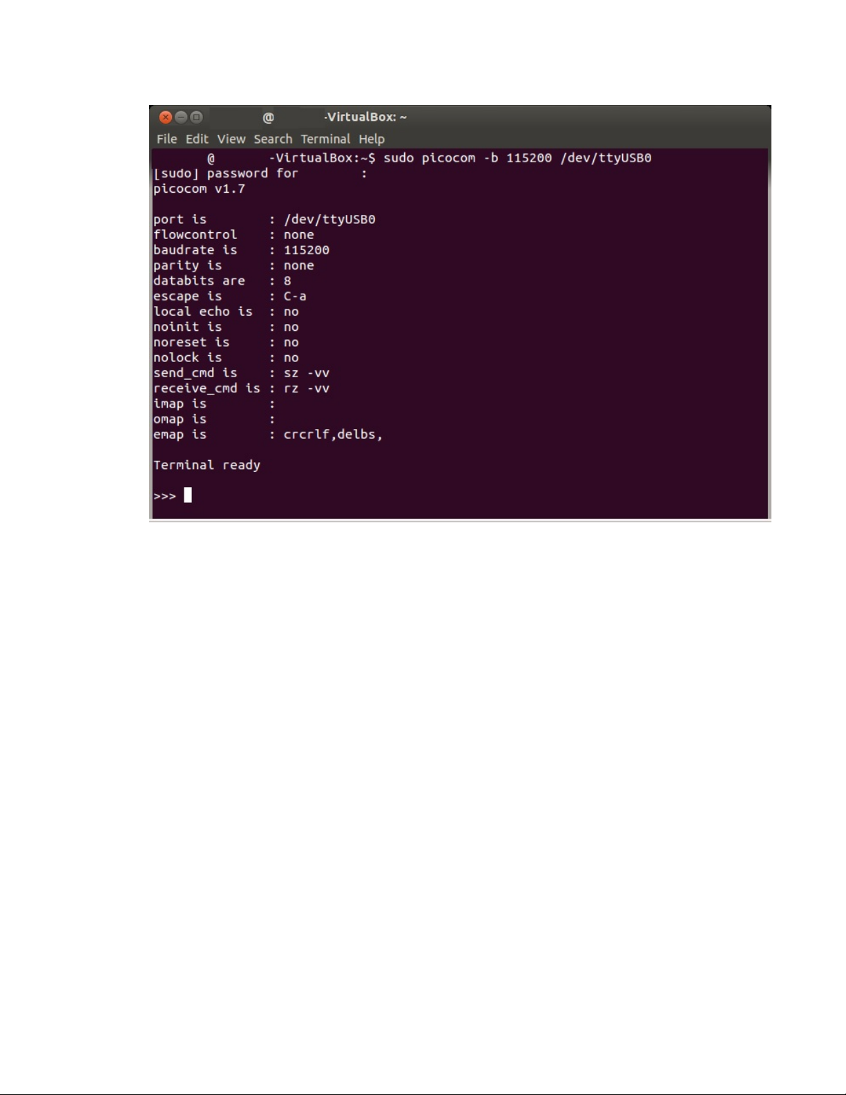
Get started with MicroPython Use picocom in Linux
Now you can type MicroPython commands at the >>> prompt.
Digi XBee Cellular 3G Global Embedded Modem User Guide
67
Page 68

Update the firmware
You should update your XBee to the latest firmware to take advantage of all the latest fixes and
features. Refer to the topics below for information about the available update methods.
Digi strongly recommends that you devise a plan to update the firmware after initial deployment. For
more information, see Create a plan for device firmware updates.
Create a plan for device component firmware updates 69
Update the device firmware 70
Digi XBee Cellular 3G Global Embedded Modem User Guide
68
Page 69

Update the firmware Create a plan for device component firmware updates
Create a plan for device component firmware updates
You should update your XBee to the latest firmware to take advantage of all the latest fixes and
features. Security issues or software bugs may be identified which require firmware updates to
resolve. In addition, Digi periodically releases new device firmware which includes new features and
improves reliability and performance of existing features. You should evaluate and test the new
releases and update your firmware to take advantage of the improvements and new features.
Note For Cellular 3G modems, you cannot update the firmware on the cellular component.
Note Digi will not accept responsibility for customers who have not planned to update their units.
Please review the information provided below.
Please review the suggestions below:
n If updates will be performed using a PC, XCTU version 6.5.0 or later is able to perform device
firmware updates.
n If updates will be performed using a host processor, see Use a host processor to update the
modem firmware for XBee devices over UART.
n If updates will be performed over-the-air (OTA):
l If your XBee application is using API mode, monitor for Modem Status (0x8A) API frames
with status codes 0x38 through 0x3A. These modem status frames inform the XBee's host
application about ongoing and completed or failed firmware updates.
l If your XBee application is using Transparent mode, test your application to determine
whether it is tolerant to over-the-air firmware updates of the cellular component and XBee
firmware. If your application cannot tolerate the network connection being non-functional
for up to 30 minutes (for example, if the XBee will be reset in a shorter time than that), do
not use over-the-air updates, and be aware that firmware updates to the XBee require
user intervention.
o
If the XBee firmware is updated over-the-air using Digi Remote Manager: After the new
firmware image has been downloaded and validated, the XBee modem reboots
automatically to install the firmware. The XBee then resets into the new firmware once
the update is complete, which may take up to 60 seconds.
Digi XBee Cellular 3G Global Embedded Modem User Guide
69
Page 70
Update the firmware Update the device firmware
Update the device firmware
You should update the device firmware on your XBee to the latest version to take advantage of all the
latest fixes and features. Security issues or software bugs may be identified which require firmware
updates to resolve. In addition, Digi periodically releases new firmware which includes new features
and improves reliability and performance of existing features.
n For information about updating the cellular firmware, see Update the cellular firmware.
The table below lists update methods you can use and the instructions for each method.
Method
Instructions
XCTU Update the device firmware using XCTU
FOTA (DRM)
n Update the firmware from the Devices page in
Remote Manager
n Update the firmware using web services in Remote
Manager
n Schedule a task to update the device firmware
using Remote Manager
API
Use a host processor to update the modem firmware for
XBee devices over UART
Update the device firmware using XCTU
You can use XCTU to update the device firmware.
Prerequisites
n Windows PC
n Digi XCTU version 6.5.0 or newer. You should upgrade XCTU to the latest version.
n Make sure the device is added to XCTU. See Add a device to XCTU.
To update the device firmware:
1.
Launch XCTU .
2.
Click the Configuration working modes button .
3. From the Radio Modules list, select the device that you want to update.
4. Click Update firmware. The Update the radio module firmware dialog appears and displays
the available and compatible device firmware for the selected XBee module.
5. Make sure you check the Force the module to maintain its current configuration box.
6. Select the product family of the XBee module, the function set, and the latest firmware version.
7. Click Update. A dialog displays update progress. Click Show details for details of the firmware
update process.
Digi XBee Cellular 3G Global Embedded Modem User Guide
70
Page 71

Update the firmware Update the device firmware
Update the firmware from the Devices page in Remote Manager
You can update the device firmware for one or multiple devices from the Devices page in Remote
Manager.
Before you begin, verify the TCP connection method your device uses to connect to Remote Manager:
query once a day or use a persistent TCPconnection. See TCP connection.
To perform a firmware update:
1. Download the updated firmware file for your device from Digi's support site.
a. Go to the Digi XBee Cellular 3G support page.
b. Scroll down to the Firmware Updates section.
c. Locate and click XBee Cellular 3G AT&T Global Firmware to download the zip file.
d. Unzip the file.
2. Set up a persistent connection to connect the device to Remote Manager. See Restore
persistent connection to a remote XBee.
3. Log into Remote Manager.
4. In your Remote Manager account, click Device Management > Devices.
5. Select the first device you want to update. To select multiple devices (must be of the same
type), press the Control key and select additional devices.
6. Click More in the Devices toolbar and select More > Update > Update Firmware. The Update
Firmware dialog appears.
7. Click Browse to select the .ebin file that you unzipped earlier.
8. Click Update Firmware. The updated devices automatically reboot when the updates are
complete.
Note The update is immediately rejected and an error is returned if the device is going into
sleep mode or is being shut down. See Clean shutdown.
9. When all changes are complete, disconnect the device from Remote Manager.
Update the firmware using web services in Remote Manager
Remote Manager supports both synchronous and asynchronous firmware update using web services.
The following examples show how to perform an asynchronous firmware update. See the Remote
Manager documentation for more details on firmware updates.
Before you begin, verify the TCP connection method your device uses to connect to Remote Manager:
query once a day or use a persistent TCPconnection. See TCP connection.
Note You must use XCTU to update the cellular component's firmware.
1. Download the updated firmware file for your device from Digi's support site.
a. Go to the Digi XBee Cellular 3G support page.
b. Scroll down to the Firmware Updates section.
c. Locate and click XBee Cellular 3G AT&T Global Firmware to download the zip file.
d. Unzip the file and locate the .ebin file in the unzipped directory.
Digi XBee Cellular 3G Global Embedded Modem User Guide
71
Page 72

Update the firmware Update the device firmware
2. Send an HTTP SCI request to Remote Manager with the contents of the downloaded .ebin file
converted to base64 data. Refer to the the following examples:
Examples for .ebin:
n Example: Update the XBee firmware synchronously using a local file
n Example: Update the XBee firmware synchronously using a Remote Manager Data File
Example: Update the XBee firmware synchronously using a local file
import base64
import requests
# Location of firmware image
firmware_path = 'XBXC.ebin'
# Remote Manager device ID of the device being updated
device_id = '00010000-00000000-03526130-70153378'
# Remote Manager username and password
username = "my_Remote_manager_username"
password = "my_remote_manager_password"
url = 'https://remotemanager.digi.com/ws/sci'
# Get firmware image
fw_file = open(firmware_path, 'rb')
fw_data = fw_file.read()
fw_data = base64.encodebytes(fw_data).decode('utf-8')
# Form update_firmware request
data = """
<sci_request version="1.0">
<update_firmware filename="firmware.ebin">
<targets>
<device id="{}"/>
</targets>
<data>{}</data>
</update_firmware>
</sci_request>
""".format(device_id, fw_data)
# Post request
r = requests.post(url, auth=(username, password), data=data)
if (r.status_code != 200) or ("error" in r.content.decode('utf-8')):
print("firmware update failed")
else:
print("firmware update success")
Example: Update the XBee firmware synchronously using a Remote Manager Data
File
To update the XBee firmware synchronously with Python 3.0, but using the device firmware image
already uploaded to Remote Manager, upload the device's *.ebin firmware to Remote Manager:
1. Download the updated firmware file for your device from Digi's support site. This is a zip file
containing .ebin and .mxi files for import.
2. Unzip the file and locate the .ebin inside the unzipped directory.
Digi XBee Cellular 3G Global Embedded Modem User Guide
72
Page 73

Update the firmware Update the device firmware
3. Log in to Remote Manager.
4. Click the Data Services tab.
5. Click Data Files.
6. Click Upload Files; browse and select the *.ebin firmware file to upload it.
7. Send an HTTP SCI request to Remote manager with the path of the .ebin file; see the example
below.
import base64
import requests
# Location of firmware image on Remote Manager
firmware_path = '~/XBXC.ebin'
# Remote Manager device ID of the device being updated
device_id = '00010000-00000000-03526130-70153378'
# Remote Manager username and password
username = "my_remote_manager_username"
password = "my_remote_manager_password"
url = 'https://remotemanager.digi.com/ws/sci'
# Form update_firmware request
data = """
<sci_request version="1.0">
<update_firmware filename="firmware.ebin">
<targets>
<device id="{}"/>
</targets>
<file>{}</file>
</update_firmware>
</sci_request>
""".format(device_id, firmware_path)
# Post request
r = requests.post(url, auth=(username, password), data=data)
if (r.status_code != 200) or ("error" in r.content.decode('utf-8')):
print("firmware update failed")
else:
print("firmware update success")
Use a host processor to update the modem firmware for XBee devices over UART
This process explains how to update the modem firmware for XBee Cellular devices.
Update the modem firmware
1. Make sure you have the correct version of the modem firmware for your XBee device.
2. Enter programming (bootloader) mode. Use one of the following methods: ATcommands or
hardware signaling.
Digi XBee Cellular 3G Global Embedded Modem User Guide
73
Page 74

Update the firmware Update the device firmware
n ATcommands
a. Send the %P command. The %P command must be sent an argument derived from
the SL parameter of the module being updated. The argument is the value of SL
added to the value 0xDB8A and then masked by performing a bitwise-AND with
0x3FFF.
i. Run ATSL to get the address value, which is in hex.
ATSL
123456
ii. Add bitwise-AND with 0x3FFF.
(0xDB8A + 0x123456) & 0x3FFF= 0x0FE0
iii. Send the command AT%PFE0.
AT%PFE0
b. You will receive an error, which is expected.
c. Send the FRcommand to reboot and enter into bootloader.
n Invoke the bootloader with hardware signaling
a. De-Assert RTS (pin 16).
b. Assert DTR (pin 9).
c. Put DIN in a low state (break) (pin 3).
d. Reset the module (pin 5).
e. Release the break on DIN (pin 3) The module should now be in bootloader at 38400
baud.
3. Once the module is in programming (bootloader) mode, configure the local serial port to
38400/8/N/1.
4. Get the hardware version of the radio module from the bootloader.
a. Send the V command. The response to that command has the following format:
XXXXYYYYZZAABBBBCCCCCCCCCCCCCCCC
Digi XBee Cellular 3G Global Embedded Modem User Guide
n XXXX: The hardware version.
See ATHV, little endian.
n YYYY: The hardware revision.
See AT%R, little endian.
n ZZ: The hardware compatibility
number. See AT%C.
n AA: Unused and should be 0.
n BBBB: The hardware series. See
ATHS, little endian.
n CCCCCCCCCCCCCCCC: The
serial number.
74
Page 75

Update the firmware Update the device firmware
5. If possible, change the baud rate of the serial port to optimize the firmware update process.
Send the X command to the bootloader.
n The bootloader answers with the maximum supported baud rate (in ASCII) and, just
after that, the bootloader changes its baud rate to that value. Change your baud rate to
match the max supported rate.
n If the bootloader does not answer to this command, remain at the current rate.
6. Send the I command (initialization command). This command erases the current firmware from
the device.
7. Transfer the firmware to the device using the transfer protocol shown below.
Transfer the firmware to the device
1. You must split the file into 512 byte blocks.
2. Transfer each block using the following structure, with block index and CRC16 sent in little
endian byte:
P [2 bytes for block index] [block data with page size length] [2 bytes for CRC16]
Note CRC16 is calculated only with the bytes of the page to be sent, and is initialized with
0x0000. The polynomial used for the CRC16 is 0x8005.
3. After each block is transfered, wait for a response. Options are:
n 0x55 - ACK: This is the expected answer.
n 0x12: Checksum/CRC16 error.
n 0x13: Flash write/verify error.
Note If an error occurs, you may try to transfer each block up to three times.
4. Verify and write the firmware to flash.
a. Send the C command (verify) to verify and write the firmware to the flash.
b. Verify that the answer to this command is 0x55 (ACK). Any other result is an error.
5. Wait a couple of seconds for the firmware to be installed and start running.
Digi XBee Cellular 3G Global Embedded Modem User Guide
75
Page 76

Technical specifications
Interface and hardware specifications 77
RF characteristics 77
Networking specifications 77
Power requirements 79
Power consumption 79
Electrical specifications 80
Regulatory approvals 81
Digi XBee Cellular 3G Global Embedded Modem User Guide
76
Page 77

Technical specifications Interface and hardware specifications
Interface and hardware specifications
The following table provides the interface and hardware specifications for the device.
Specification Value
Dimensions 24.38 mm x 32.94 mm (0.960 x 1.297 in)
Weight 5 g (0.18 oz)
Operating temperature
Antenna connector
Digital I/O 13 I/O lines, I2C
ADC 4 10-bit analog inputs
Analog input voltage range 0 - 2.5 V
Cellular chipset u-blox SARA-R410M-028
Form factor Digi XBee 20-pin through-hole
SIM size 4FF Nano
Specification Value
Dimensions 2.438 x 3.294 cm (0.960 x 1.297 in)
Weight 5 g (0.18 oz)
Operating temperature
Antenna connector U.FL
-40 to +85 °C
Cellular: U.FL
Bluetooth: U.FL
-40 to +85 °C
-30 to +70 °C if 2G fallback mode is enabled
Digital I/O 13 I/O lines
ADC 4 10-bit analog inputs
RF characteristics
The following table provides the RF characteristics for the device.
Specification Value
Transmit power Up to 24 dBm, Power Class 3
2G fallback: up to 33 dBm, Power Class 4
Receive sensitivity Up to -111 dBm
Networking specifications
The following table provides the networking and carrier specifications for the device.
Digi XBee Cellular 3G Global Embedded Modem User Guide
77
Page 78

Technical specifications Networking specifications
Specification Value
Carrier and
technology
AT&T and Verizon LTE-M
T-Mobile NB-IoT in US
Vodafone and Deutsche Telekom NB-IoT in Europe
Compatible with other LTE-M carriers, see supported bands
Supported bands LTE FDD bands:
n Band 12 (700 Mhz)
n Band 28 (700 MHz)
n Band 13 (700 MHz)
n Band 20 (800 MHz)
n Band 26 (850 MHz)
n Band 18 (850 MHz)
n Band 5 (850 MHz)
n Band 19 (850 MHz)
n Band 8 (900 MHz)
n Band 4 (1700 MHz)
n Band 3 (1800 Mhz)
n Band 2 (1900 MHz)
n Band 25 (1900 MHz)
n Band 1 (2100 MHz)
1
LTE TDD bands:
n Band 39 (1900 MHz)
Security Digi Trustfence™
Downlink/uplink
LTE M1
speeds
n up to 300 kb/s DL
n up to 375 kb/s UL
LTE NB1
n up to 27.2 kb/s DL
n up to 62.5 kb/s UL
Duplex mode Half-duplex
Addressing
options
SMS and IP-based protocols may not be available. Check with your carrier's
specifications for LTE-M\NB-IoT.
1
Band 25 is only supported by products containing SARA-R410M-02B-01 and newer. Band 25 is for LTE CATM1
only.
Digi XBee Cellular 3G Global Embedded Modem User Guide
78
Page 79

Technical specifications Power requirements
Specification Value
Addressing
options
Technology 3G Universal Mobile Telecommunications Service (UMTS)/High Speed Packet
Supported bands Band 19 (800 MHz)
Security Digi Trustfence™ security with secure boot, encrypted storage, protected JTAG,
Downlink/uplink
speeds
TCP/IP,UPD, and SMS
Access (HSPA) with 2G fallback
Band 5 (850 MHz)
Band 8 (900 MHz)
Band 2 (1900 MHz)
Band 1 (2100 MHz)
TLS 1.2
Up to 7.2 Mb/s / 5.76 Mb/s
Power requirements
The following table provides the power requirements for the device.
Specification Value
Supply voltage 3.3 to 4.3 V
1
Specification Value
Normal supply voltage range 3.0 to 5.5 VDC (3.8 to 5 V for 2G fallback mode)
Extended supply voltage range
Power consumption
The peak current was measured from multiple tested units.
Specification State
Connected mode (TX + RX)
current
Tx + RX current Active transmit, 24 dBm @ 5.0 V 425 mA
Rx + ACK current Active receive @ 3.3 V 224 mA
1
See DO (Device Options) for more information on enabling and using the 2G fallback feature.
2
See the 2G fallback power consumption table for further details.
2
2.7 to 5.5 VDC (3.6 to 5.5 VDC for 2G fallback mode)
Active transmit, 24 dBm @ 3.3 V 702 mA
Average current (3G
mode)
Digi XBee Cellular 3G Global Embedded Modem User Guide
79
Page 80

Technical specifications Electrical specifications
Average current (3G
Specification State
Rx + ACK current Active receive @ 5 V 160 mA
Idle current Idle/connected, listening @ 3.3 V 87 mA
Idle current Idle/connected, listening @ 5 V 72 mA
mode)
Sleep current Notconnected,Deep
Electrical specifications
The following table provides the electrical specifications for the XBee Cellular Modem.
Symbol Parameter Condition Min Typical Max Units
VCC_IO Internal
supply
voltage for
I/O
VCC_IO Internal
supply
voltage for
I/O
VI Input
voltage
range on
any I/O pin
While in
deep
sleep and
during
initial
power up
In normal
running
mode
10 µA
Sleep@3.3V
VCC - 0.3 V or 3.3 V, whichever is
lower
3.3 V V
-0.3 VCC_
3.3 V
IO+0.3
V
VIL Input low
voltage
VIH Input high
voltage
VOL Voltage
output low
VOH Voltage
output
high
I_IN Input
leakage
current on
I/O pins
Digi XBee Cellular 3G Global Embedded Modem User Guide
Sinking 1
mA, VCC_
IO = 3.3 V
Sourcing 1
mA, VCC_
IO = 3.3 V
High Z
state; I/O
connected
to Ground
or VCC_IO
0.7*VCC_IO V
0.3*VCC_IOV
0.05*VCC_
IO
0.9*VCC_
IO
0.1 100 nA
V
V
80
Page 81

Technical specifications Regulatory approvals
Symbol Parameter Condition Min Typical Max Units
RPU Internal
pull-up
resistor
RPD Internal
pull-down
resistor
Enabled 40 kΩ
Enabled 40 kΩ
Regulatory approvals
The following table provides the regulatory and carrier approvals for the device.
Specification Value
United States Contains FCC ID: XPY1CGM5NNN
Innovation, Science and Economic Development Canada
(ISED)
Europe (CE) Yes
Australia ACMA Yes, RCM
New Zealand RSM Yes, R-NZ
RoHS Lead-free and RoHS compliant
Contains IC: 8595A-1CGM5NNN
PTCRB certification No
AT&T end device certified Yes
Digi XBee Cellular 3G Global Embedded Modem User Guide
81
Page 82

Hardware
Mechanical drawings 83
Pin signals 83
XBee header connector requirements 85
RSSI PWM 85
SIM card 85
Associate LED functionality 85
Development boards 87
Digi XBee Cellular 3G Global Embedded Modem User Guide
82
Page 83
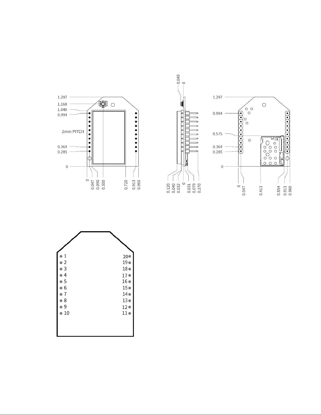
Hardware Mechanical drawings
Mechanical drawings
The following figures show the mechanical drawings for the XBee Cellular Modem. All dimensions are
in inches.
For XBee header information, see XBee header connector requirements.
Pin signals
The pin locations are:
The following table shows the pin assignments for the through-hole device. In the table, low-asserted
signals have a horizontal line above signal name.
Digi XBee Cellular 3G Global Embedded Modem User Guide
83
Page 84

Hardware Pin signals
Pin Name Direction Default Description
Pin Name Direction Default Description
V
1
2 DOUT Output Output UART Data Out
3
4 DIO12 / SPI_MISO Either Disabled Digital I/O 12 or SPI Slave
5 RESET Input
6 PWM0 / RSSI / DIO10 Either Output PWM Output 0 / RX Signal
7 DIO11 Either Disabled Digital I/O 11
8 [reserved] Do not connect
9
CC
DIN / CONFIG
DTR / SLEEP_RQ/ DIO8
Input Input UART Data In
Either Disabled Pin Sleep Control Line or
Power supply
Output line
Strength Indicator / Digital
I/O 10
Digital I/O 8
10 GND Ground
11 DIO4 / SPI_MOSI Either Disabled Digital I/O 4 or SPI Slave
Input Line
CTS / DIO7
12
ON /SLEEP/DIO9
13
14 VREF - Feature not supported on
15 Associate / DIO5 Either Output Associated Indicator, Digital
RTS / DIO6
16
AD3/DIO3/SPI_SS
17
18 AD2 / DIO2 / SPI_CLK Either Disabled Analog Input 2 or Digital I/O
Either Output Output Clear-to-Send Flow
Control or Digital I/O 7
Output Output Module Status Indicator or
Digital I/O 9
this device. Used on other
XBee devices for analog
voltage reference.
I/O 5
Either Disabled Input Request-to-Send Flow
Control, Digital I/O 6
Either Disabled Analog Input 3 or Digital I/O
3, SPI low enabled select
line
2, SPI Clock line
AD1/DIO1/ SPI_ATTN
19
20 AD0/DIO0 Either Input Analog Input 0, Digital I/O 0
Digi XBee Cellular 3G Global Embedded Modem User Guide
Either Disabled
Analog Input 1 or Digital I/O
1, SPI Attention line output
84
Page 85
Hardware XBee header connector requirements
Pin connection recommendations
The recommended minimum pin connections are VCC, GND, DIN, DOUT, RTS, DTR and RESET.
Firmware updates require access to these pins.
XBee header connector requirements
The XBee header connectors require the following attributes:
n female
n 2 mm pitch
n 10 positions
n single row
RSSI PWM
The XBee Cellular Modem features an RSSI/PWM pin (pin 6) that, if enabled, adjusts the PWM output to
indicate the signal strength of the cellular connection. Use P0 (DIO10/PWM0 Configuration) to enable
the RSSI pulse width modulation (PWM) output on the pin. If P0 is set to 1, the RSSI/PWM pin outputs a
PWM signal where the frequency is adjusted based on the received signal strength of the cellular
connection.
The RSSI/PWM output is enabled continuously unlike other XBee products where the output is enabled
for a short period of time after each received transmission. If running on the XBIB development board,
DIO10 is connected to the RSSI LEDs, which may be interpreted as follows:
Number of LEDs turned
PWM duty cycle
79.39% or more 3 -83 dBm or higher
62.42% to
79.39%
45.45% to
62.42%
Less than
45.45%
on Received signal strength (dBm)
2 -93 to -83 dBm
1 -103 to -93 dBm
0
SIM card
The XBee Cellular Modem uses a 4FF (Nano) size SIM card.
CAUTION! Never insert or remove SIM card while the power is on!
Associate LED functionality
The following table describes the Associate LED functionality. For the location of the Associate LED on
the XBIB-U development board, see number 6 on the XBIB-U-DEV reference.
Less than -103 dBm, or no cellular network
connection
Digi XBee Cellular 3G Global Embedded Modem User Guide
85
Page 86
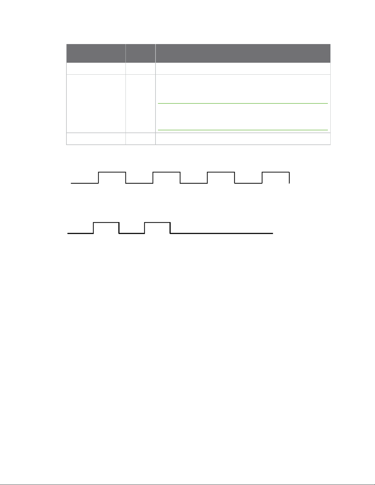
Hardware Associate LED functionality
Blink
LED status
On, solid Not joined to a mobile network.
timing Meaning
Double blink
Standardsingleblink 1second Normal operation.
The normal association LED signal alternates evenly between high and low as shown below:
Where the low signal means LED off and the high signal means LED on.
When CI is not 0 or 0xFF, the Associate LED has a different blink pattern that looks like this:
½second
The last TCP/UDP/SMS attempt failed. If the LED has this pattern,
you may need to check DI (Remote Manager Indicator) or CI
(Protocol/Connection Indication) for the cause of the error.
Note This pattern applies only to the Transparent mode. Other
transmission modes do not affect the Associate LED blink
pattern.
Digi XBee Cellular 3G Global Embedded Modem User Guide
86
Page 87
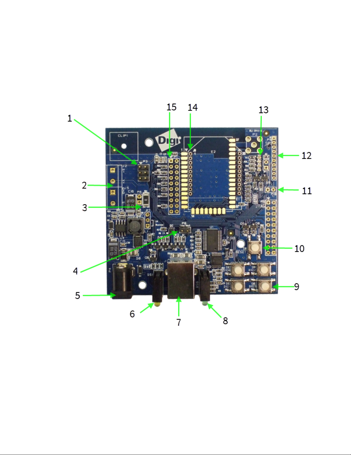
Hardware Development boards
Development boards
XBIB-U-DEV reference
This picture shows the XBee USB XBIB-U-DEV development board and the table that follows explains
the call-outs in the picture.
Digi XBee Cellular 3G Global Embedded Modem User Guide
87
Page 88
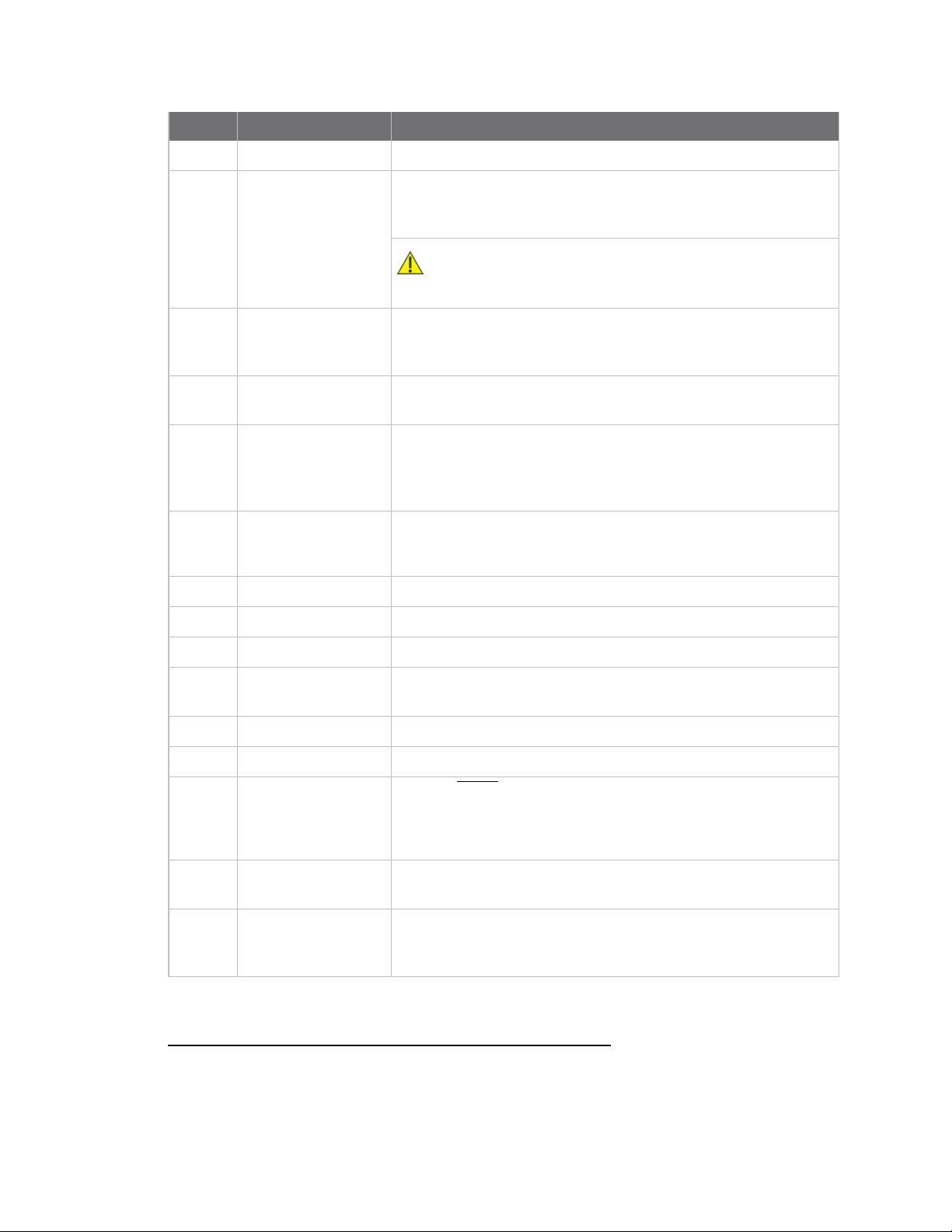
Hardware Development boards
Number Item Description
1 Programmingheader Header used to program XBee programmable devices.
2 Self power module
Advanced users only—voids the warranty. Depopulate R31 to
power the device using V+ and GND from J2 and J5. You can
connect sense lines to S+ and S- for sensing power supplies.
CAUTION: Voltage is not regulated. Applying the incorrect
voltage can cause fire and serious injury.
1
3 Current testing Depopulating R31 allows a current probe to be inserted across P6
terminals. The current though P6/R31 powers the device only.
Other supporting circuitry is powered by a different trace.
4 Loopback jumper Populating P8 with a loopback jumper causes serial transmissions
both from the device and from the USB to loopback.
5 DC barrel plug: 6-20V Greater than 500 mA loads require a DC supply for correct
operation. Plug in the external power supply prior to the USB
connector to ensure that proper USB communications are not
interrupted.
6 LED indicator
Yellow: Modem sending serial/UART data to host.
Green: Modem receiving serial/UART data from host.
Red: Associate.
7 USB Connects to your computer.
8 RSSI indicator
See RSSI PWM. On the XBIB-U, more lights are better.
9 User buttons Connected to DIO lines for user implementation.
10 Reset button Press the reset button to reset the device to the default
configuration.
11 SPI power Connect to the power board from 3.3 V.
12 SPI Only used for surface-mount devices.
13 Indicator LEDs
DS5: ON/SLEEP
DS2: DIO12, the LED illuminates when driven low.
DS3: DIO11, the LED illuminates when driven low.
DS4: DIO4, the LED illuminates when driven low.
14 Through-hole XBee
sockets
15 20-pin header Maps to standard through-hole XBee pins. Male, Samtec header,
part number: TSW-110-26-L-D. 2.54 mm / .100" pitch and row
spacing.
1
Powering the board with J2 and J5 without R31 removed can cause shorts if the USB or barrel plug power are
connected. Applying too high a voltage destroys electronic circuitry in the device and other board components
and/or can cause injury.
Digi XBee Cellular 3G Global Embedded Modem User Guide
88
Page 89
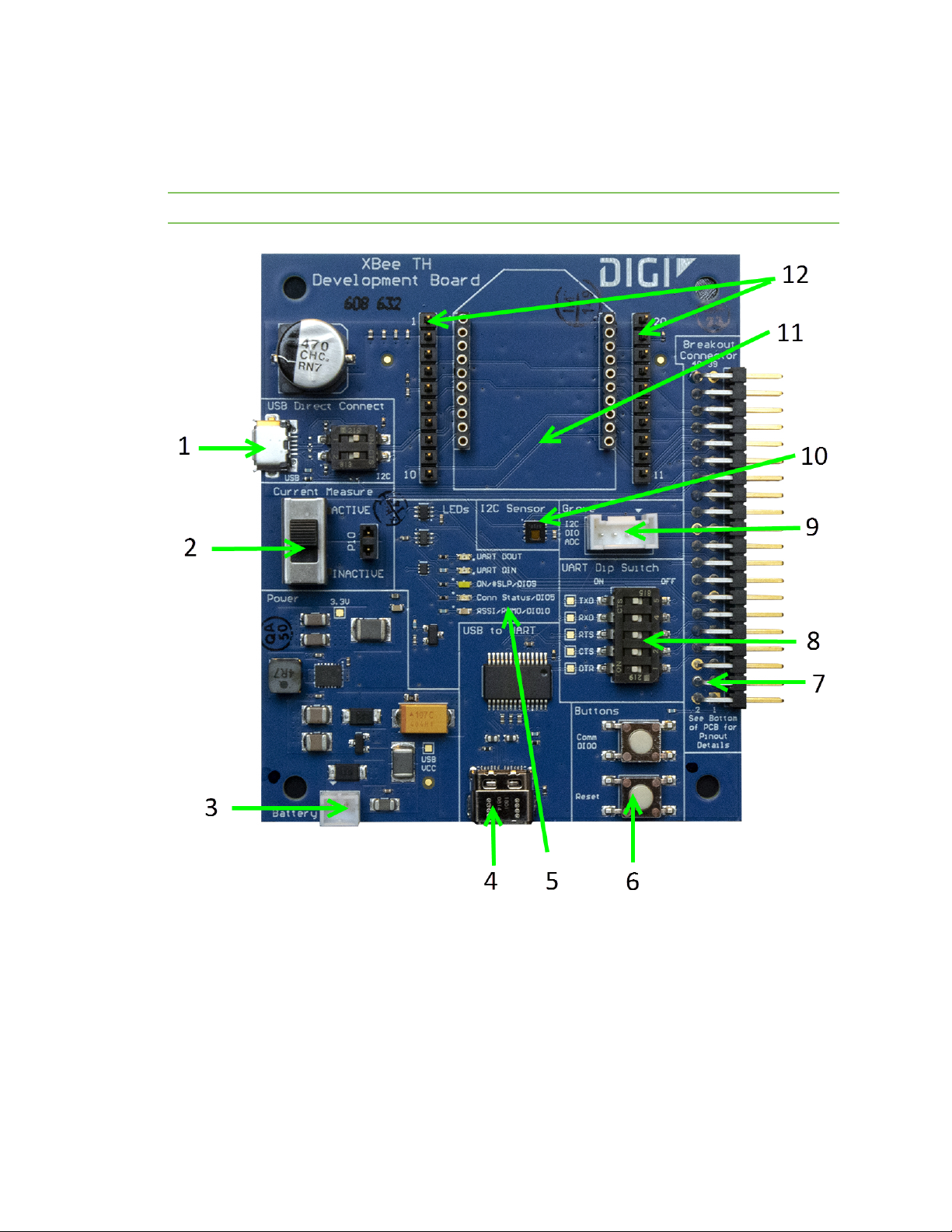
Hardware Development boards
XBIB-CU-TH reference
This picture shows the XBee-CU-TH development board and the table that follows explains the
callouts in the picture.
Note This module is sold separately.
Digi XBee Cellular 3G Global Embedded Modem User Guide
89
Page 90

Hardware Development boards
Number Item Description
1 Secondary USB
(USB MICRO B)
and DIP Switch
2 Current
Measure
3 Battery
Connector
Secondary USB Connector for direct programming of modules on some
XBee units. Flip the Dip switches to the right for I2C access to the
board; flip Dip switches to the left to disable I2C access to the board.
The USB_P and USB_N lines are always connected to the XBee,
regardless of Dip switch setting. USB communications will fail if
switches are not in the left position or if XBEE is not configured to
enable USB communications.
This USB port is not designed to power the module or the board. A USBC cable or battery port is required to power the board. Cable can be
connected at any time, with the XBe powered or unpowered.
WARNING! USB micro port should not be connected when
used with XBees that do not support USB communications.
Large switch controls whether current measure mode is active or
inactive. When inactive, current can freely flow to the VCC pin of the
XBee. When active, the VCC pin of the XBee is disconnected from the 3.3
V line on the development board. This allows current measurement to
be conducted by attaching a current meter across the jumper P10.
If desired, a battery can be attached to provide power to the
development board. The voltage can range from 2 V to 5 V. The positive
terminal is on the left.
If the USB-C connector is connected to a computer, the power will be
provided through the USB-C connector and not the battery connector.
WARNING! Battery current discharge rating must be enough
to support 5 W or more.
WARNING! There is no circuit to prevent over discharge of
battery. Battery must contain its own protection circuitry.
WARNING! Move UART switches to the OFF position when
using battery or external power or for when the XBee and
the USB-C connector is not powering the UART.
Note Power supply outputs 3.3 V to XBee regardless of input voltage as
long as current requirement can be met to achieve power consumption
of devices.
Digi XBee Cellular 3G Global Embedded Modem User Guide
90
Page 91
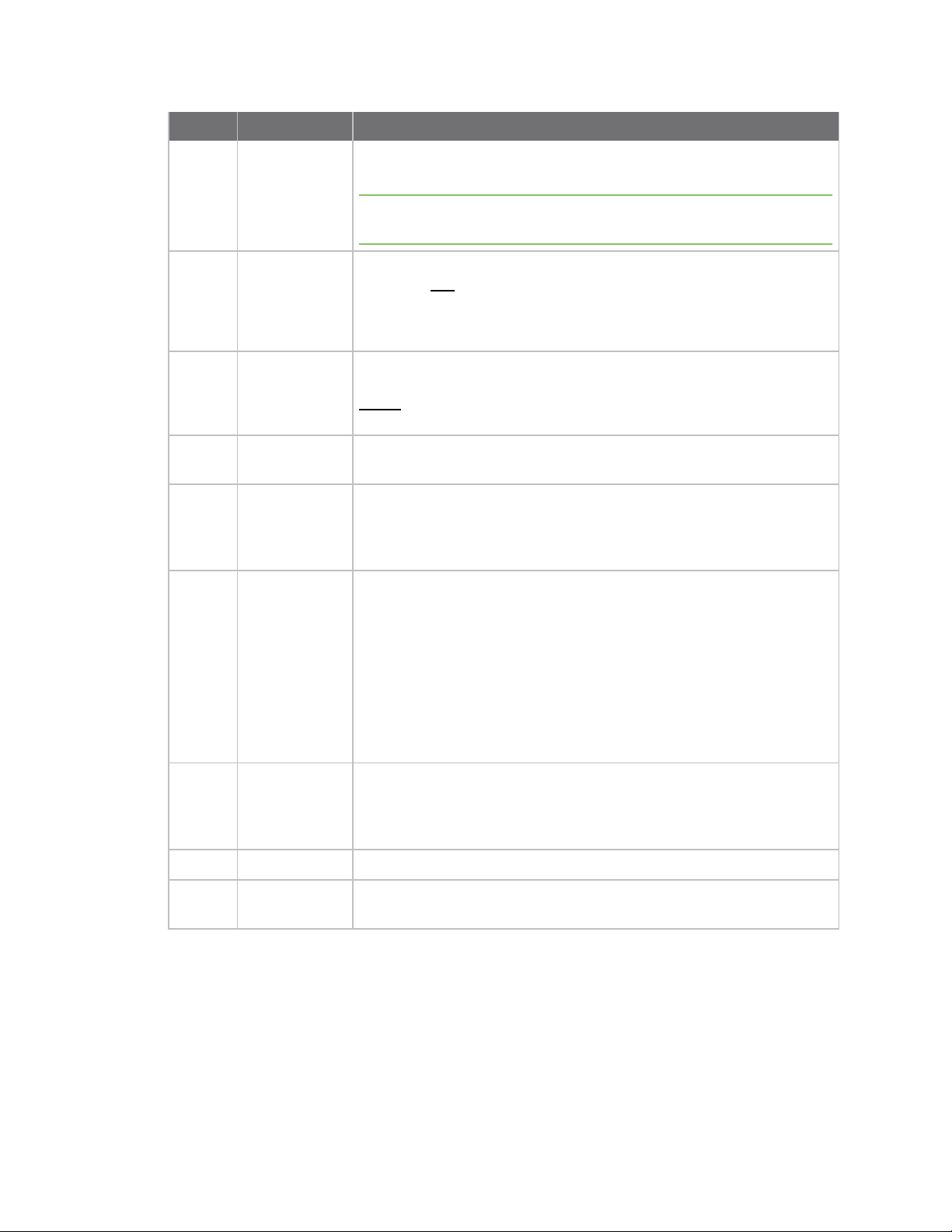
Hardware Development boards
Number Item Description
4 USB-C
Connector
5 LED indicator Red: UART DOUT (modem sending serial/UART data to host)
6 User Buttons Comm DIO0 Button connects the Commissioning/DIO0 pin to GND when
7 Breakout
Connector
8 UART Dip
Switch
9 Grove
Connector
Provides power and UART communications for the XBEE and
development board.
Note Requires USB 3.0 to supply 1 amp of required current. USB 2.0
ports that cannot supply at least 1 amp cannot be used.
Green: UART DIN (modem receiving serial/UART data from host)
White: ON/SLP/DIO9
Blue: Connection Status/DIO5
Yellow: RSSI/PWM0/DIO10
pressed.
RESET button resets the XBee module when pressed.
This 40 pin connects to various XBee pins as shown on the silkscreen on
the bottom of the board.
Push Dip switches to the right (OFF position) to disconnect USB-toUART conversion chip from the XBee. This allows UART lines to be
individually selected to connect through the breakout connector or the
USB-C interface.
This connector attaches I2C-enabled devices to the development board.
Note that I2C needs to be available on the XBee in the board for this
functionality to be used.
Move both USB direct connect switches to the right (closed position)
and disconnect the USB micro port for correct operation of the I2C to
connector.
Pin 1: I2C_CLK/XBee DIO1
Pin2: I2C_SDA/XBee DIO11
Pin3: VCC
Pin4: GND
10 Temp/Humidity
Sensor
11 XBee Socket This is the socket for the XBee (TH form factor).
12 XBee Test
Point Pins
Digi XBee Cellular 3G Global Embedded Modem User Guide
This part is a Texas Instruments HDC1080 temperature and humidity
sensor connected through I2C on XBee pins DIO1 and DIO11. Move both
USB direct connect switches to the right (closed position) and
disconnect the USB micro port for correct operation of the I2C sensor.
Allows easy access to pins 1 to 20 of the XBee.
91
Page 92

Hardware Development boards
XBIB-C-GPS reference
This picture shows the XBIB-C-GPS module and the table that follows explains the callouts in the
picture.
Note This GPS module is sold separately and requires an XBIB-CU-TH development board.
Note You run a demo using MicroPython to parse UART to GPS communications. see Run the
MicroPython GPSdemo.
Digi XBee Cellular 3G Global Embedded Modem User Guide
92
Page 93

Hardware Development boards
Number Item Description
1 40-pin
header
2 GPS
unit
This header is used to connect the XBIB-C-GPS board to a compatible XBIB
development board. Insert the XBIB-C-GPS module slowly with alternating
pressure on the upper and lower parts of the connector. Do not bend pins during
insertion or removal process.
Contains GPS module CAM-M8Q-0-10. Proper orientation is with the board laying
flat, with the GPS module having a clear view of the sky.
Interface with the XBIB-C-GPS module
The XBee Cellular Modem can interface with the XBIB-C-GPS board through the 40-pin header. This
header is designed to fit into XBIB-C development board. This allows the XBee Cellular Modem in the
XBIB-C board to communicate with the XBIB-C-GPS board—provided the XBee device has MicroPython
capabilities (see this link to determine which devices have MicroPython capabilities). There are two
ways to interface with the XBIB-C-GPS board: through the host board’s Secondary UART or through
the I2C compliant lines.
The following picture shows a typical setup:
Digi XBee Cellular 3G Global Embedded Modem User Guide
93
Page 94

Hardware Development boards
I2C communication
There are two I2C lines connected to the host board through the 40-pin header, SCL and SDA. I2C
communication is performed over an I2C-compliant Display Data Channel. The XBIB-C-GPS module
operates in slave mode. The maximum frequency of the SCL line is 400 kHz. To access data through
the I2C lines, the data must be queried by the connected XBee Cellular Modem.
For more information about I2C Operation see the I2C section of the Digi Micro Python Programming
Guide.
For more information on the operation of the XBIB-C-GPS board see the CAM-M8 datasheet. Other
CAM-M8 documentation is located here.
UART communication
UART (RX and TX) are pins connected from the XBIB-C-GPS to the host board by the 40-pin header. By
default, the UART on the XBIB-C-GPS board is active and sends GPS readings once every second. The
baud rate of the UART is 9600 baud.
For more information about using Micro Python to communicate to the XBIB-C-GPS module, see Class
UART.
Run the MicroPython GPSdemo
The Digi MicroPython github repository contains a GPS demo program that parses the GPS NMEA data
from the UART and prints them.
Note If you are unfamiliar with MicroPython on XBee, see Get started with MicroPython. For more
detailed information, refer to the Digi MicroPython Programming Guide.
Step 1: Clone or download the XBee MicroPython repository
1. Navigate to: https://github.com/digidotcom/xbee-micropython/
2. You must either clone or download a zip file of the repository. You can use either method.
n Clone: If you are familiar with Git, follow the standard Gitprocess to clone the
repository.
n Download
a. Click Download zip to download a zip file of the repository to the download folder
of your choosing.
b. Extract the repository to a location of your choosing on your hard drive.
Step 2: Edit the MicroPython file
1. Navigate to the location that you created in Step 1.
2. Navigate to: samples/gps_uart
3. Open the MicroPython file: main.py
Step 3: Run the program
1. Copy the file onto your device's root filesystem directory.
2. Open XCTU and use the MicroPython Terminal to run the demo.
3. Type <CTRL>-R from the MicroPython prompt to run the code.
Digi XBee Cellular 3G Global Embedded Modem User Guide
94
Page 95

Antenna recommendations
Antenna placement
For optimal cellular reception, keep the antenna as far away from metal objects and other electronics
(including the XBee Cellular Modem) as possible. Often, small antennas are desirable, but come at the
cost of reduced range and efficiency.
Digi XBee Cellular 3G Global Embedded Modem User Guide
95
Page 96

Design recommendations
Power supply considerations 97
Add a capacitor to the RESET line 97
Heat considerations 97
Custom configuration: Create a new factory default 98
Clean shutdown 99
SIMcards 100
Digi XBee Cellular 3G Global Embedded Modem User Guide
96
Page 97
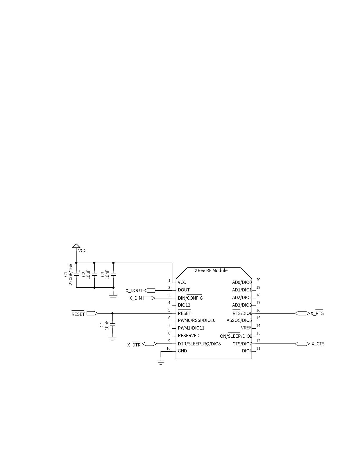
Design recommendations Power supply considerations
Power supply considerations
When considering a power supply, use the following design practices.
1. Power supply ripple should be less than 75 mV peak to peak.
2. The power supply should be capable of providing a minimum of 1.5 A at 3.3 V (5 W). Keep in
mind that operating at a lower voltage requires higher current capability from the power
supply to achieve the 5 W requirement.
3. Place sufficient bulk capacitance on the XBee VCC pin to maintain voltage above the minimum
specification during inrush current. Inrush current for VCC = 3.3 V is about 2 A during initial
power up of cellular communications and wakeup from sleep mode. We recommend a
minimum of 220 µF of capacitance on the VCC pin.
4. Place a 10 nF ceramic capacitor very close to the XBee Cellular Modem VCC pin to decrease
high frequency noise.
5. Use a wide power supply trace or power plane to ensure it can handle the peak current
requirements with minimal voltage drop. We recommend that the power supply and trace be
designed such that the voltage at the XBee VCC pin does not vary by more than 0.1 V between
light load (~0.5 W) and heavy load (~3 W).
6. If you use DO (Device Options) to enable 2G fallback mode, the power supply must be capable
of supplying 11.5W and the minimum input voltage is 3.8V (for example 3.0A @ 3.8V). In
addition, we recommend 1000µF of bulk capacitance on the VCC pin. The supply should never
drop below 3.6 V during TX bursts.
Add a capacitor to the RESET line
In high EMI noise environments, we recommend adding a 10 nF ceramic capacitor very close to pin 5.
Heat considerations
Depending on the use case, your application may require a heat sink. Use a non-conductive thermal
gasket to make contact to the heat sink. The gasket should be thick enough to ensure that contact
with the tallest component does not cause damage when pressure is applied to a secure heat sink.
Digi XBee Cellular 3G Global Embedded Modem User Guide
97
Page 98
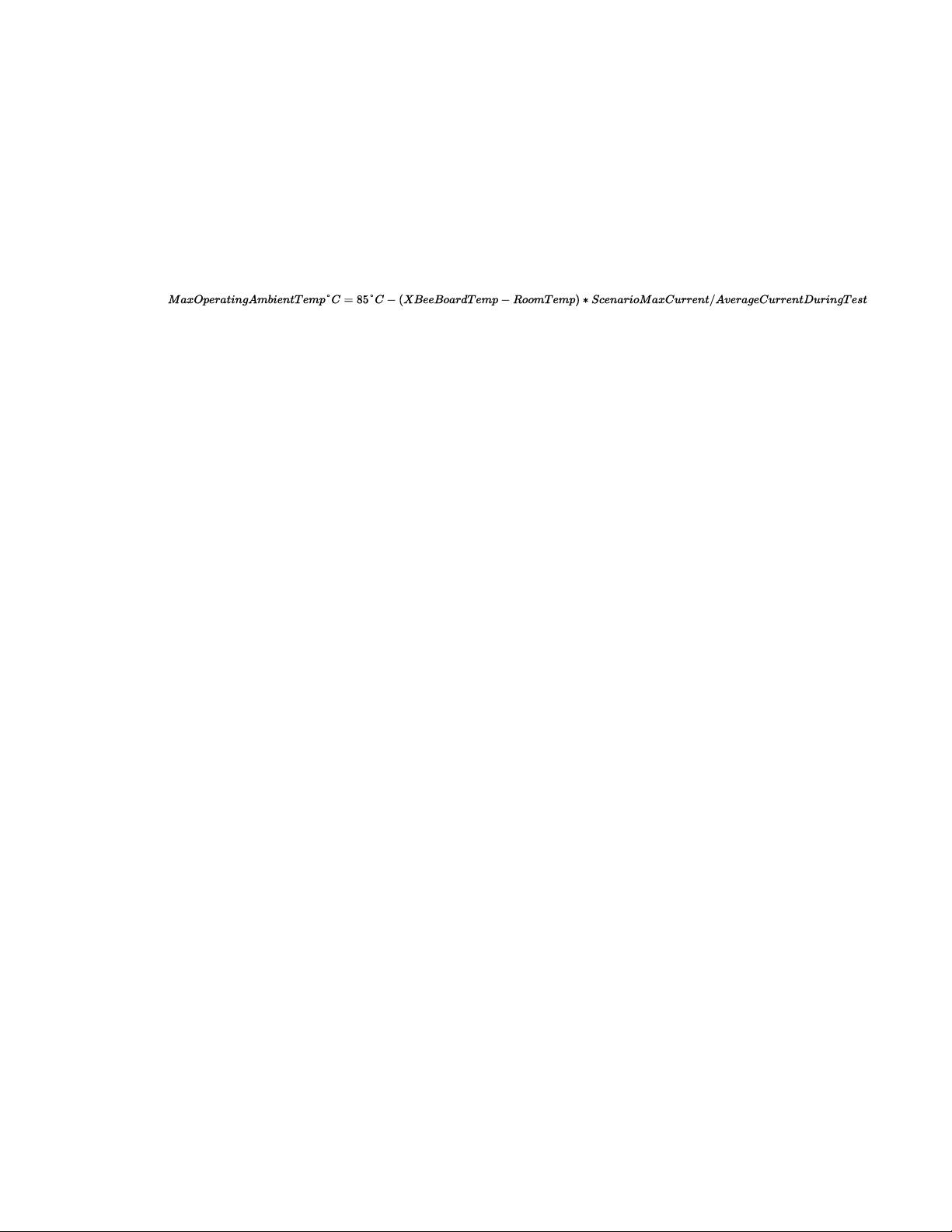
Design recommendations Custom configuration: Create a new factory default
We recommend connecting the heat sink to the bottom side of the XBee Cellular Modem (SIM card
side). Alternatively, you can attach the heat sink to the top side of the unit (U.FL side), but cooling is
less effective on this side.
We do not recommend operating at hot temperatures without verifying that the device will not
overheat in the operating circumstances.
The operation temperature of the unit can be approximated for different current draws and extreme
cases by the equation below. For best results, attach a temperature probe on the bottom of the XBee
Cellular Modem, about 5 mm higher than the SIM card slot. Alternatively use TP (Temperature) to
query the current temperature of the device's processor.
Where
1. XBeeBoardTemp is the temperature of the XBee Cellular Modem at steady state.
a. Use the TPcommand to help estimate the temperature when attaching a temperature
probe is not practical, but for reliable results, you must use a temperature probe.
2. RoomTemp is the temperature of the ambient air.
3. AverageCurrentDuringTest is the average current measured during test.
4. ScenarioMaxCurrent is the maximum current expected for the device.
The results may vary by implementation and scenario. You should always perform sufficient testing to
ensure that the XBee Cellular Modem does not exceed temperature specifications.
Add a fan to provide active cooling
The XBee Cellular Modem can become hot if you use it in the maximum upload or download scenarios,
see Heat considerations. One method of heat mitigation is to attach a fan to the device to provide
active cooling.
If you attach a fan, use P1 (DIO11/PWM1 Configuration) to enable this functionality on pin 7. Set P1 to
1, which turns the fan on when the device gets above 70 °C and the cellular component is running, and
off below 65 °C.
Custom configuration: Create a new factory default
You can create a custom configuration that is used as a new factory default. This feature is useful if
you need, for example, to maintain certain settings for manufacturing or want to ensure a feature is
always enabled. When you perform a factory reset on the device using the RE command, the custom
configuration is set on the device rather than the original factory default settings.
For example, by default the baud rate is set to 9600. You can create a custom configuration where the
baud rate is set to 115200 by default. When you use the RE command to reset the device to the
factory defaults, the baud rate is set to the custom configuration (115200) rather than the original
factory default (9600).
The custom configuration is stored in non-volatile memory. You can continue to create and save
custom configurations until the device's memory runs out of space. If there is no space left to save a
configuration, XBee returns an error.
You can use the !C command to clear or overwrite a custom configuration at any time.
Digi XBee Cellular 3G Global Embedded Modem User Guide
98
Page 99
Design recommendations Clean shutdown
Set a custom configuration
1. Open XCTU on the device.
2. Enter Command mode.
3. Perform the following process for each configuration that you want to set as a factory default.
a. Issue an AT%F command. This command enables you to enter a custom configuration.
b. Issue the custom configuration command. For example: ATBD 7. This command sets the
default for the baud rate to 115200.
Clear all custom configurations on a device
After you have set configurations using the AT%F command, you can return all configurations to the
original factory defaults.
1. Open XCTU on the device.
2. Enter Command mode.
3. Issue AT!C.
Clean shutdown
WARNING! Improper shutdown of the modem may result in the underlying cellular module
becoming irrecoverably unresponsive.
Digi strongly recommends performing a clean shutdown procedure on your XBee cellular devices
before removing power from the devices. Performing a shutdown allows the module to unregister
from the cellular network and safely store operating parameters. Failure to shutdown properly has
the potential to result in delays resuming network operation and in some rare instances may result in
an unrecoverable module failure.
You can use any of the following methods to perform a clean shutdown.
SD (Shutdown) command
You should use the SD command to safely shut down a device before removing power. This is the
recommended method.
Issue the SDcommand. When the shut down process is complete, the device returns OK. After the
device responds OK, you can safely remove power from the device.
The device will return ERROR if any of the following actions are in progress:
n Over-the-air update of the cellular component
n Local update of the cellular component
n Over-the-air update of the XBee firmware.
In addition, if the radio can't be fully shut down within two minutes, the device returns ERROR.
You can verify the state of the device using the AIcommand. After you issue the SD command and a
response has been returned (either OKor ERROR), issue the AIcommand. If the shutdown was
successful, 2D is returned.
Digi XBee Cellular 3G Global Embedded Modem User Guide
99
Page 100

Design recommendations SIMcards
Sleep feature
The recommended approach is to use one of the available sleep configurations such as the Pin Sleep
feature (SM=1) or sleeping through MicroPython (xbee.sleep_now()). When the module has gone to
sleep and the SLEEP pin (pin 13) is low, power may safely be removed.
1. Initiate sleep: Assert SLEEP_RQ
2. Wait for sleep state to be entered: SLEEP pin (pin 13) low.
3. Power off the device.
Airplane mode
Change the XBee configuration to use Airplane mode (AM=1). This puts the XBee into a safe state for
shutdown.
1. Set AM=1.
2. Apply configuration change.
3. Wait 30 seconds to allow time for shutdown to occur.
4. Power off the device.
SIMcards
n For best performance, use a SIM card with gold-plated contacts.
n Because vibrations in your application environment may cause unexpected SIM card failures
due to fretting between the SIM card and the card holder, Digi strongly recommends that you
apply a thin layer of dielectric grease to the SIM contacts prior to installing the SIM cards.
Digi XBee Cellular 3G Global Embedded Modem User Guide
100
 Loading...