

Page 1

XBee3® 802.15.4
Radio Frequency (RF) Module
User Guide
Page 2

Revision history—90002273
Revision Date Description
A February 2018 Initial release.
Trademarks and copyright
Digi, Digi International, and the Digi logo are trademarks or registered trademarks in the United
States and other countries worldwide. All other trademarks mentioned in this document are the
property of their respective owners.
© 2018 Digi International Inc. All rights reserved.
Disclaimers
Information in this document is subject to change without notice and does not represent a
commitment on the part of Digi International. Digi provides this document “as is,” without warranty of
any kind, expressed or implied, including, but not limited to, the implied warranties of fitness or
merchantability for a particular purpose. Digi may make improvements and/or changes in this manual
or in the product(s) and/or the program(s) described in this manual at any time.
Warranty
To view product warranty information, go to the following website:
www.digi.com/howtobuy/terms
Send comments
Documentation feedback: To provide feedback on this document, send your comments to
techcomm@digi.com.
Customer support
Digi Technical Support: Digi offers multiple technical support plans and service packages to help our
customers get the most out of their Digi product. For information on Technical Support plans and
pricing, contact us at +1 952.912.3444 or visit us at www.digi.com/support.
XBee3® 802.15.4 RF Module User Guide
2
Page 3

Contents
XBee3® 802.15.4 RF Module User Guide
Applicable firmware and hardware 8
Change the firmware protocol 8
Getting started
Verify kit contents 10
Assemble the hardware 10
Plug in the XBee3 802.15.4 RF Module 11
How to unplug an XBee module 12
Configure the device using XCTU 12
Configure remote devices 12
Configure the devices for a range test 13
Perform a range test 14
Modes
Serial modes 18
Transparent operating mode 18
API operating mode 18
Command mode 18
Enter Command mode 19
Send AT commands 19
Apply command changes 20
Exit Command mode 20
Operation
Software libraries 22
Addressing 22
Send packets to a specific device 22
Addressing modes 22
Maximum payload 23
Maximum payload rules 23
Working with Legacy devices 23
Networking 24
MAC Mode configuration 24
XBee retries configuration 25
Transmit status based on MAC mode and XBee retries configurations 25
XBee3® 802.15.4 RF Module User Guide
3
Page 4

Peer-to-peer networks 26
Clear Channel Assessment (CCA) 26
CCA operations 27
Serial interface 27
Serial receive buffer 27
Serial transmit buffer 27
UART data flow 28
Flow control 28
Sleep support 30
Sleep modes 30
Sleep parameters 30
Sleep current 30
Sleep pins 31
Node discovery 31
Remote configuration commands 31
Send a remote command 31
Apply changes on remote devices 32
Remote command responses 32
AT commands
Network commands 34
ID (Extended PAN ID) 34
C8 (802.15.4 Compatibility) 34
NI (Node Identifier) 36
NT (Node Discover Timeout) 36
ND (Network Discover) 36
NO (Node Discovery Options) 37
NP (Maximum Packet Payload Bytes) 37
Addressing commands 38
SH (Serial Number High) 38
SL (Serial Number Low) 38
MY (16-bit Source Address) 38
DH (Destination Address High) 38
DL (Destination Address Low) 39
RR (XBee Retries) 39
TO (Transmit Options) 39
MM (MAC Mode) 40
DD (Device Type Identifier) 40
RF interfacing commands 41
PL (TX Power Level) 41
PP (Output Power in dBm) 41
CH (Operating Channel) 41
CA (CCA Threshold) 42
RN (Random Delay Slots) 42
DB (Last Packet RSSI) 42
UART serial interfacing 43
BD (Interface Data Rate) 43
NB (Parity) 44
SB (Stop Bits) 44
AP(API Enable) 45
RO (Packetization Timeout) 45
FT command 45
D6 (DIO6/RTS) 46
D7 (DIO7/CTS) 46
XBee3® 802.15.4 RF Module User Guide
4
Page 5

Command mode options 46
CN (Exit Command mode) 47
CT (Command Mode Timeout) 47
GT (Guard Times) 47
CC (Command Character) 47
Sleep settings 47
SM (Sleep Mode) 48
D8 (DIO8/DTR/SLP_RQ) 48
D9 (DIO9/ON_SLEEP) 48
I/O settings commands 49
D0 (DIO0 Configuration) 49
D1 (DIO1 Configuration) 49
D2 (DIO2 Configuration) 50
D3 (DIO3 Configuration) 50
D4 (DIO4 Configuration) 51
D5 (DIO5/Associate Configuration) 51
P0 (DIO10/PWM0 Configuration 52
P1 (DIO11 Configuration) 52
P5 (DIO15 Configuration) 53
PR (Pull-up/Down Resistor Enable) 53
PD (Pull Up/Down Direction) 54
LT command 54
Diagnostic commands 55
AI (Association Indication) 55
EA (ACK Failures) 55
EC (CCA Failures) 55
VR (Firmware Version) 56
VL (Version Long) 56
VH command 56
HV (Hardware Version) 56
%V command 56
TP command 57
CK (Configuration CRC) 57
FR (Software Reset) 57
Memory access commands 57
AC (Apply Changes) 57
WR (Write) 58
RE (Restore Defaults) 58
Operate in API mode
API mode overview 60
API frame specifications 60
API operation (AP parameter = 1) 60
API operation-with escaped characters (AP parameter = 2) 60
API frame format 61
Calculate and verify checksums 62
Frame descriptions 64
API frames 64
TX Request: 64-bit address frame - 0x00 64
TX Request: 16-bit address - 0x01 66
AT Command Frame - 0x08 67
AT Command - Queue Parameter Value frame - 0x09 69
Remote AT Command Request frame - 0x17 70
RX Packet: 64-bit Address frame - 0x80 71
XBee3® 802.15.4 RF Module User Guide
5
Page 6

Receive Packet: 16-bit address frame - 0x81 72
AT Command Response frame - 0x88 73
TX Status frame - 0x89 75
Modem Status frame - 0x8A 77
Remote Command Response frame - 0x97 78
XBee3® 802.15.4 RF Module User Guide
6
Page 7

XBee3® 802.15.4 RF Module User Guide
XBee3 802.15.4 RF Modules are embedded solutions providing wireless end-point connectivity to
devices. These devices use the IEEE 802.15.4 networking protocol for fast point-to-multipoint or peerto-peer networking. They are designed for high-throughput applications requiring low latency and
predictable communication timing.
The XBee3 802.15.4 RF Module supports the needs of low-cost, low-power wireless sensor networks.
The devices require minimal power and provide reliable delivery of data between devices. The devices
operate within the ISM 2.4 GHz frequency band.
The XBee3 802.15.4 RF Module uses XBee3 hardware and the Silicon Labs EFR32 chipset. As the name
suggests, the 802.15.4 module is over-the-air compatible with our Legacy 802.15.4 modules (S1 and
S2C hardware).
For information about XBee3 hardware, see the XBee3 RF Module Hardware Reference Manual.
Applicable firmware and hardware 8
Change the firmware protocol 8
XBee3® 802.15.4 RF Module User Guide
7
Page 8

XBee3® 802.15.4 RF Module User Guide Applicable firmware and hardware
Applicable firmware and hardware
This manual supports the following firmware:
n 802.15.4 version 20xx
It supports the following hardware:
n XBee3
Change the firmware protocol
You can switch the firmware loaded onto the XBee3 hardware to run either of the following protocols:
n Zigbee
n 802.15.4
To change protocols, use the Update firmware feature in XCTU and select the firmware. See the
XCTU User Guide.
XBee3® 802.15.4 RF Module User Guide
8
Page 9

Getting started
This section covers the following tasks and features:
Verify kit contents 10
Assemble the hardware 10
Configure the device using XCTU 12
Configure remote devices 12
Configure the devices for a range test 13
Perform a range test 14
XBee3® 802.15.4 RF Module User Guide
9
Page 10
Getting started Verify kit contents
Verify kit contents
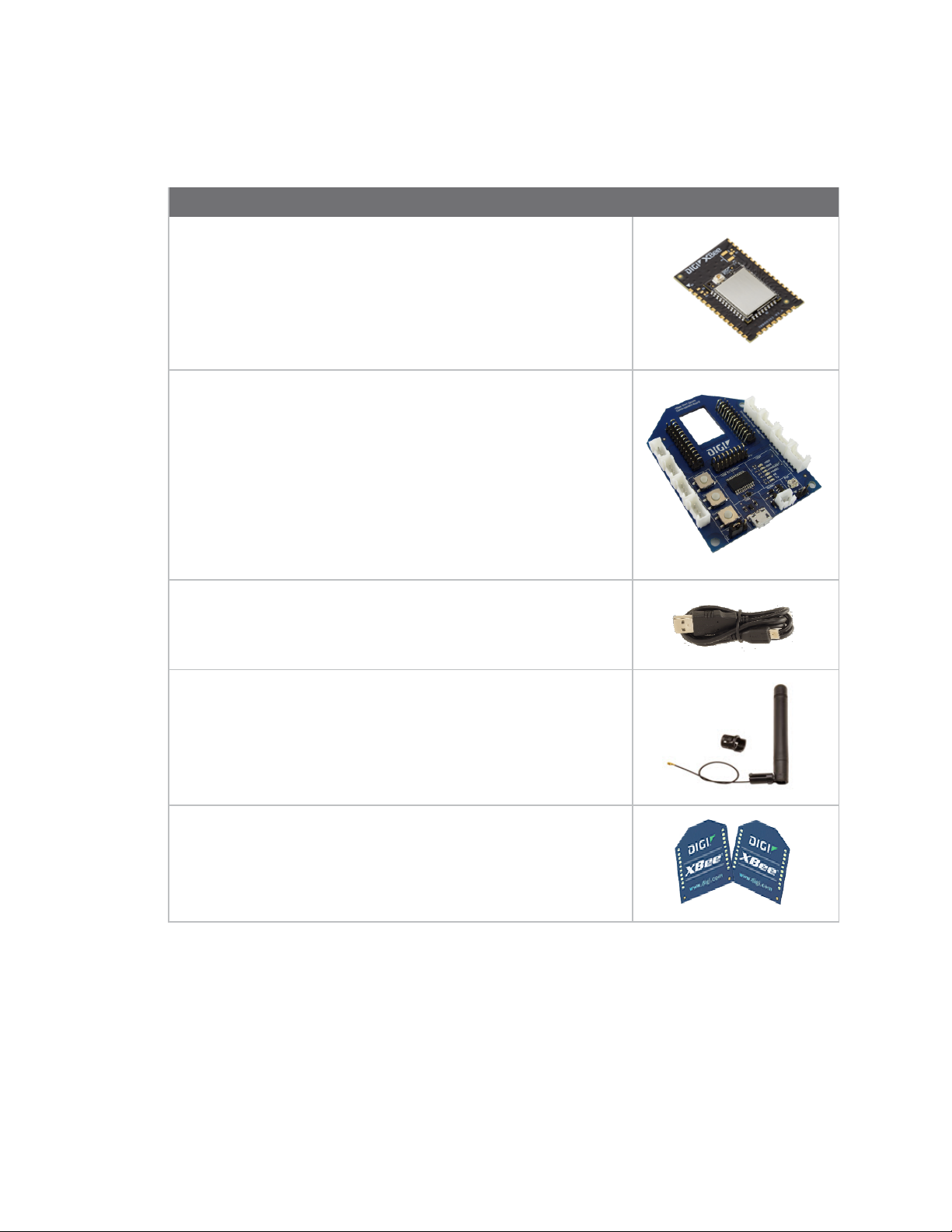
The XBee3 802.15.4 RF Module development kit contains the following components:
Part
XBee3 Zigbee SMT module (3)
XBee Grove development board (3)
Micro USB cable (3)
Antenna - 2.4 GHz, half-wave dipole, 2.1 dBi, U.FL female, articulating
(3)
XBee stickers
Assemble the hardware
This guide walks you through the steps required to assemble and disassemble the hardware
components of your kit.
n Plug in the XBee3 802.15.4 RF Module
n How to unplug an XBee module
The kit includes several XBee Grove Development Boards. For more information about this hardware,
XBee3® 802.15.4 RF Module User Guide
10
Page 11
Getting started Assemble the hardware
see the XBee Grove Development Board documentation.
Plug in the XBee3 802.15.4 RF Module
This kit includes two XBee Grove Development Boards. For more information about this hardware,
visit the XBee Grove Development Board documentation.
Follow these steps to connect the XBee devices to the boards included in the kit:
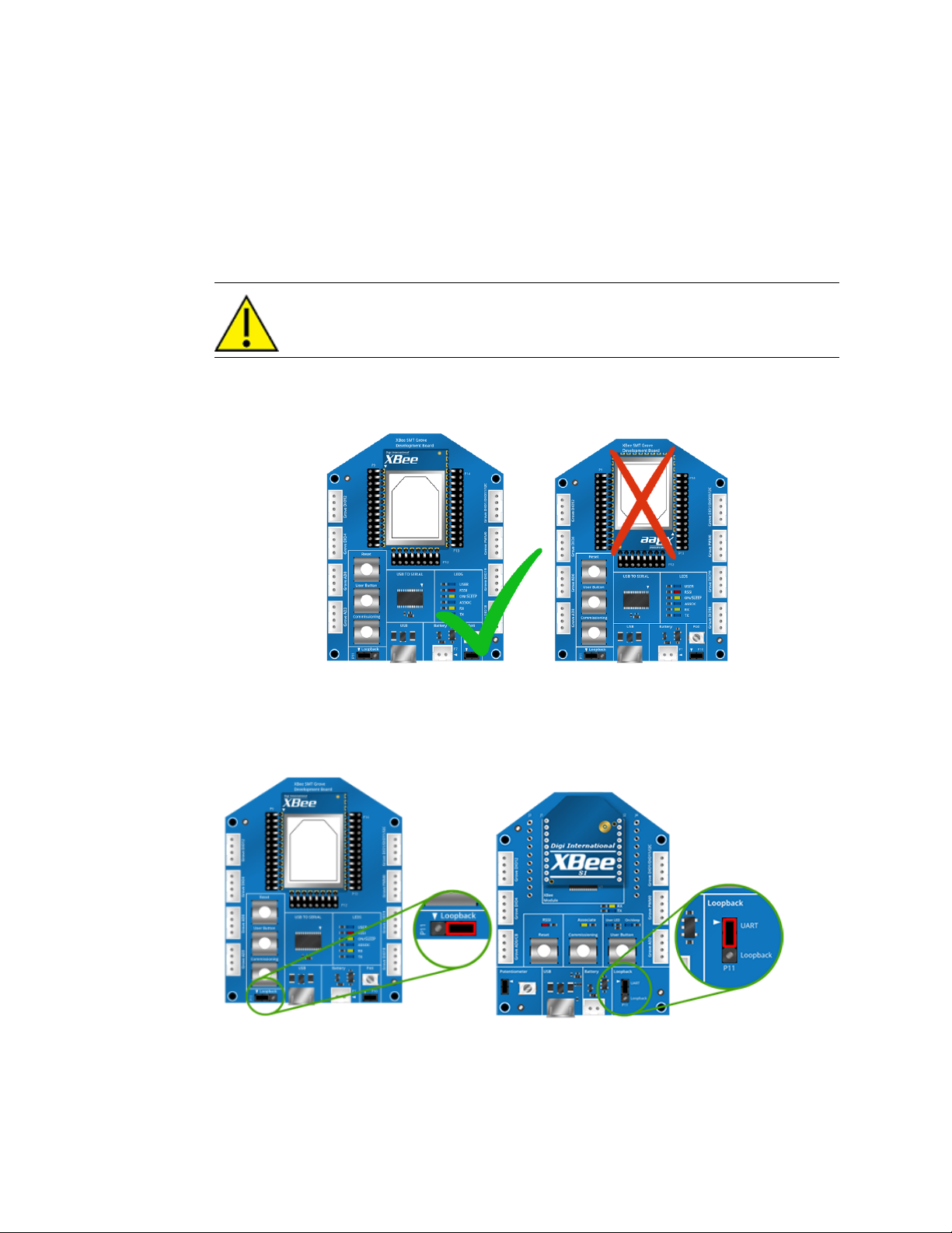
1. Plug one XBee3 802.15.4 RF Module module into the XBee Grove Development Board.
Make sure the board is NOT powered (either by the micro USB or a battery) when
you plug in the XBee module.
For XBee SMT modules, align all XBee pins with the spring header and carefully push the
module until it is hooked to the board.
2. Once the XBee module is plugged into the board (and not before), connect the board to your
computer using the micro USB cables provided.
3. Ensure the loopback jumper is in the UART position.
XBee3® 802.15.4 RF Module User Guide
11
Page 12
Getting started Configure the device using XCTU
How to unplug an XBee module
To disconnect your XBee module from the XBee Grove Development Board:
1. Disconnect the micro USB cable (or the battery) from the board so it is not powered.
2. Remove the XBee module from the board socket, taking care not to bend any of the pins.
Make sure the board is not powered when you remove the XBee module.
Configure the device using XCTU
XBee Configuration and Test Utility (XCTU) is a multi-platform program that enables users to interact
with Digi radio frequency (RF) devices through a graphical interface. The application includes built-in
tools that make it easy to set up, configure, and test Digi RF devices.
For instructions on downloading and using XCTU, see the XCTU User Guide.
Configure remote devices
You can communicate with remote devices over the air through a corresponding local device.
Note Configure the local device in API mode because remote commands only work in API mode.
Configure remote devices in either API or Transparent mode.
These instructions show you how to configure the LT command parameter on a remote device.
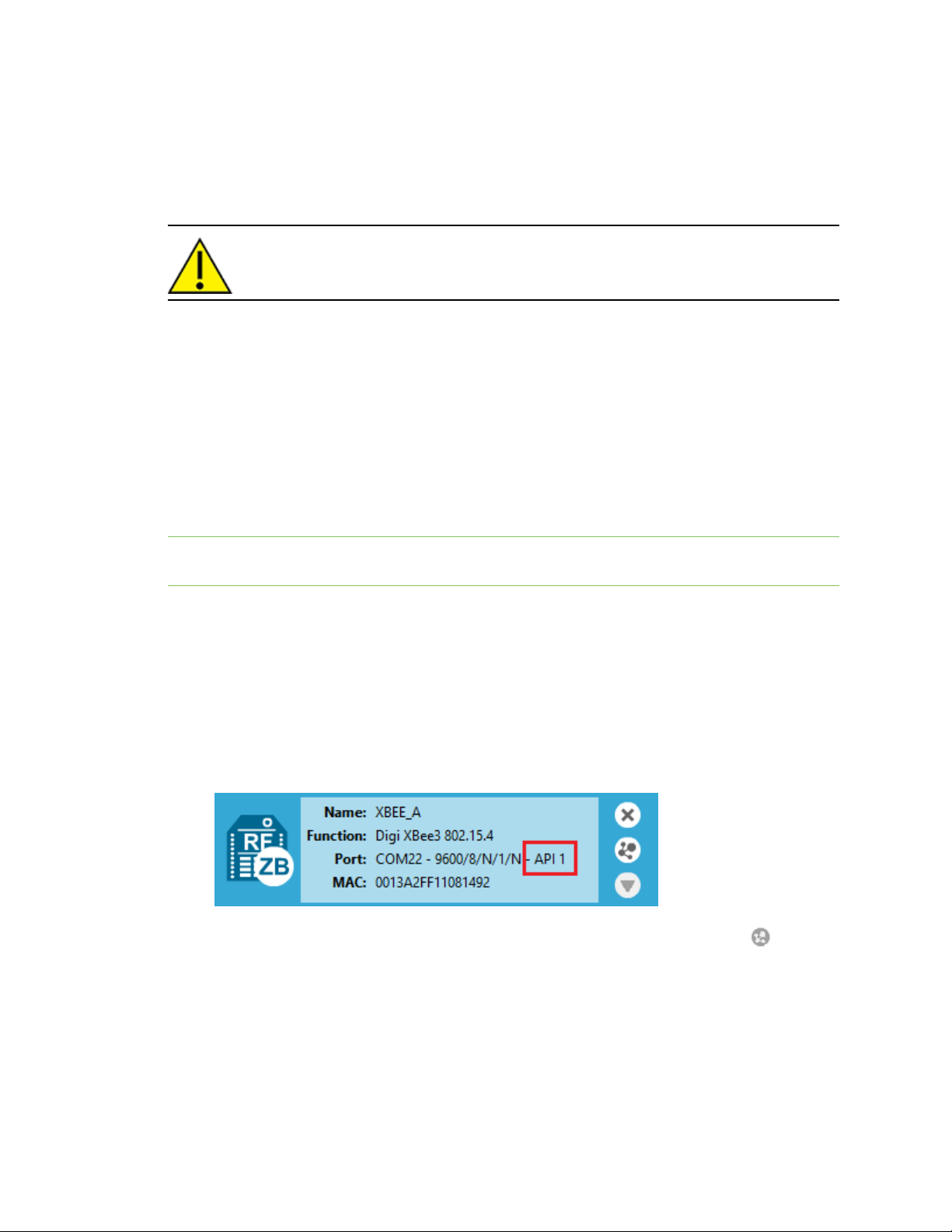
1. Add two XBee devices to XCTU.
2. Configure the first device in APImode and name it XBEE_A.
3. Configure the second device in either API or Transparent mode, and name it XBEE_B.
4. Disconnect XBEE_B from your computer and remove it from XCTU.
5. Connect XBEE_B to a power supply (or laptop or portable battery).
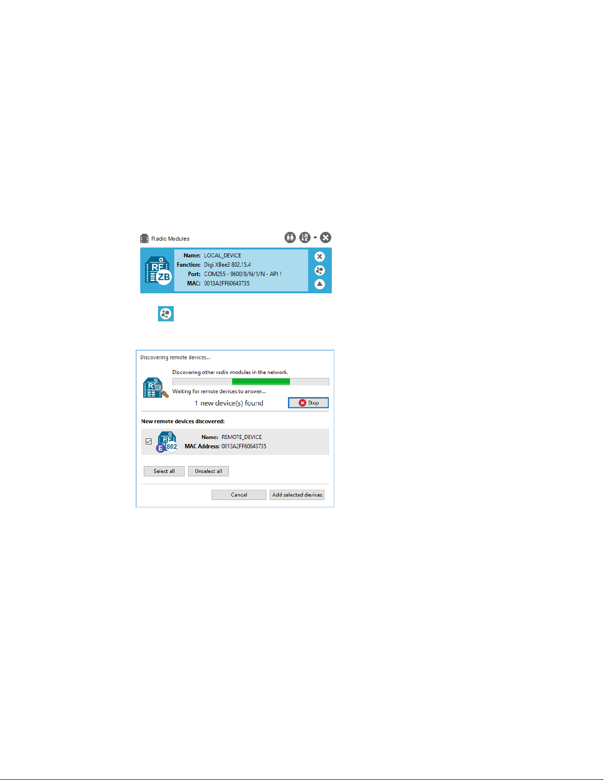
The Radio Modules area should look something like this.
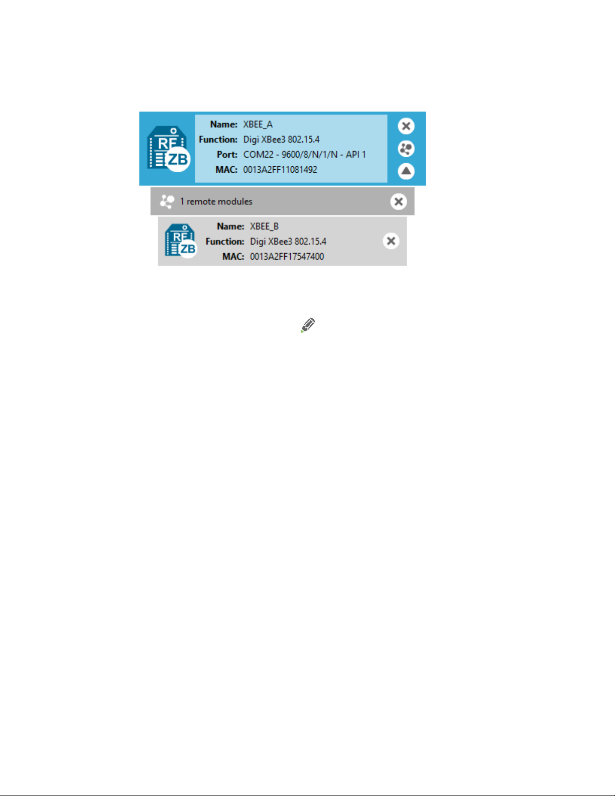
Select XBEE_A and click the Discover radio nodes in the same network button .
6.
XBee3® 802.15.4 RF Module User Guide
12
Page 13
Getting started Configure the devices for a range test
7. Click Add selected devices in the Discovering remote devices dialog. The discovered remote
device appears below XBEE_A.
8. Select the remote device XBEE_B, and configure the following parameter:
LT: FF (hexadecimal representation for 2550 ms)
Click the Write radio settings button .
9.
The remote XBee device now has a different LED blink time.
10. To return to the default LED blink times, change the LT parameter back to 0 for XBEE_B.
Configure the devices for a range test
When you connect the development board to a PC for the first time, the PC automatically installs
drivers, which may take a few minutes to complete.
1. Add the two devices to XCTU.
2. Select the first module and click the Load default firmware settings button.
3. Configure the following parameters:
ID: 2018
NI: LOCAL_DEVICE
AP: API Mode Enabled [1]
4. Click the Write radio settings button.
5. Select the other module and click the Default firmware settings button.
6. Configure the following parameters:
ID: 2015
NI: REMOTE_DEVICE
AP: Transparent mode [0] (The remote node must be in transparent mode to loop back
packets)
XBee3® 802.15.4 RF Module User Guide
13
Page 14
Getting started Perform a range test
7. Click the Write radio settings button.
After you write the radio settings for each device, their names appear in the Radio Modules
area. The Port indicates that the LOCAL_DEVICE is in API mode.
8. Disconnect REMOTE_DEVICE from the computer, remove it from XCTU, and connect it to its
own power supply.
9. Leave LOCAL_DEVICE connected to the computer.
Perform a range test
1. Go to the XCTU display for radio 1.
Click to discover remote devices within the same network. The Discover remote devices
2.
dialog appears.
3. Click Add selected devices.
XBee3® 802.15.4 RF Module User Guide
14
Page 15
Getting started Perform a range test
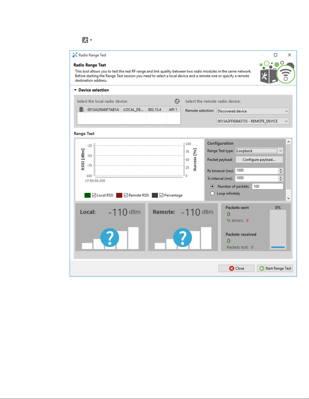
Click and select Range test. The Radio Range Test dialog appears.
4.
5. In the Select the local radio device area, select radio 1. XCTU automatically selects the
Discovered device option, and the Start Range Test button is active.
XBee3® 802.15.4 RF Module User Guide
15
Page 16
Getting started Perform a range test
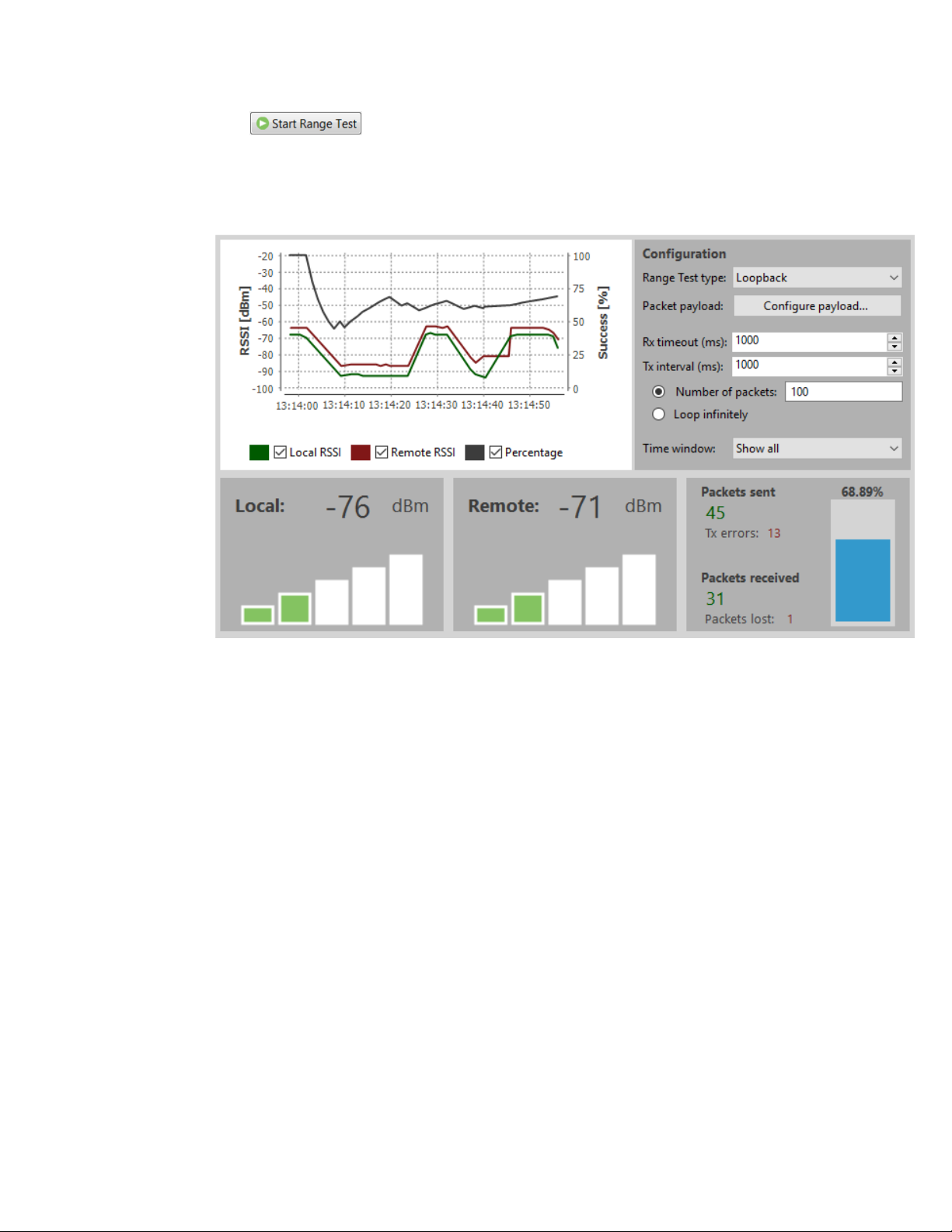
Click to begin the range test.
6.
If the test is running properly, the packets sent should match the packets received. You will
also see the received signal strength indicator (RSSI) update for each radio after each
reception.
7. Move Radio 1 around to see the resulting signal strength at different distances. You can also
test different data rates by reconfiguring the BR (data rate) parameter on both radios. When
the test is complete, click Stop Range Test.
XBee3® 802.15.4 RF Module User Guide
16
Page 17

Modes
Serial modes 18
Command mode 18
XBee3® 802.15.4 RF Module User Guide
17
Page 18

Modes Serial modes
Serial modes
The firmware operates in several different modes. Two top-level modes establish how the device
communicates with other devices through its serial interface: Transparent operating mode and API
operating mode. Use the AP command to choose Serial mode. XBee3 802.15.4 RF Modules use
Transparent operation as the default serial mode.
The following subsections describe how the serial port sends and receives data.
Transparent operating mode
Devices operate in this mode by default. The device acts as a serial line replacement when it is in
Transparent operating mode. The device queues all UART data it receives through the DIN pin for RF
transmission. When a device receives RF data, it sends the data out through the DOUT pin. You can set
the configuration parameters using Command mode.
Serial-to-RF packetization
Data is buffered in the incoming serial buffer until one of the following causes the data to be
packetized and transmitted:
1. No serial characters are received for the amount of time determined by the RO (Packetization
Timeout) parameter. If RO = 0, packetization begins when a character is received.
2. The maximum number of characters that will fit in an RF packet is received. There are a
number of factors that determine payload size. You can query the NP (Maximum Packet
Payload Bytes) to determine the maximum payload size based on current configuration. For
more information, see Maximum payload.
3. The Command mode Sequence, GT + CC + GT, (including spaces) is received; this is any data in
the serial receive buffer received before the sequence is transmitted. For more information,
see Enter Command mode.
If the device cannot immediately transmit (for instance, if it is already receiving RF data), the serial
data is stored in the serial receive buffer. The data is packetized and sent at any RO timeout or when
NP bytes are received.
If the serial receive buffer becomes full, hardware flow control must be implemented in order to
prevent overflow (loss of data between the host and device).
API operating mode
Application programming interface (API) operating mode is an alternative to Transparent mode. It is
helpful in managing larger networks and is more appropriate for performing tasks such as collecting
data from multiple locations or controlling multiple devices remotely. API mode is a frame-based
protocol that allows you to direct data on a packet basis. It can be particularly useful in large
networks where you need control over the operation of the radio network or when you need to know
which node a data packet is from. The device communicates UART or SPI data in packets, also known
as API frames. This mode allows for structured communications with serial devices.
For more information, see API mode overview.
Command mode
Command mode is a state in which the firmware interprets incoming characters as commands. It
allows you to modify the device’s firmware using parameters you can set using AT commands. When
XBee3® 802.15.4 RF Module User Guide
18
Page 19
Modes Command mode
you want to read or set any parameter of the device when operating in Transparent mode, you have
to send an AT command. Every AT command starts with the letters AT followed by the two characters
that identify the command the device issues and then by some optional configuration values.
Command mode is available on the UART interface in both Transparent and API modes.
The availability of AT commands in API mode does not imply that Command mode is available in API
mode. Also, Command mode may be entered whether or not API mode is configured, providing the
UART is the serial interface.
Enter Command mode
To get a device to switch into this mode, you must issue the following sequence: GT + CC(+++) + GT.
When GT is set to the default value, if the device sees a full second of silence in the data stream (the
guard time) followed by the string +++ (without Enter or Return) and another full second of silence, it
knows to stop sending data through and start accepting commands locally.
Note Do not press Return or Enter after typing +++ because it will interrupt the guard time silence
and prevent you from entering Command mode.
When you send the Command mode sequence, the device sends OK out the UART pin. The device may
delay sending the OK if it has not transmitted all of the serial data it received.
When the device is in Command mode, it listens for user input and is able to receive AT commands on
the UART. If CT time (default is 10 seconds) passes without any user input, the device drops out of
Command mode and returns to Receive mode.
You can customize the command character, the guard times and the timeout in the device’s
configuration settings. For more information, see CC (Command Character), CT (Command Mode
Timeout) and GT (Guard Times).
Troubleshooting
Failure to enter Command mode is often due to baud rate mismatch. Ensure that the baud rate of the
connection matches the baud rate of the device. By default, the BD parameter = 3 (9600 baud).
Send AT commands
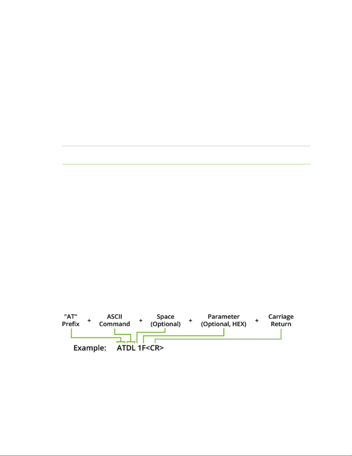
Once the device enters Command mode, use the syntax in the following figure to send AT commands.
Every AT command starts with the letters AT, which stands for "attention." The AT is followed by two
characters that indicate which command is being issued, then by some optional configuration values.
To read a parameter value stored in the device’s register, omit the parameter field.
The preceding example changes the device's destination address (Low) to 0x1F.
To store the new value to non-volatile (long term) memory, send the WR (Write) command. This allows
parameter values that you modify to persist in the device's registry after a reset. Otherwise, the
device restores parameters to the previous values after a reset.
XBee3® 802.15.4 RF Module User Guide
19
Page 20

Modes Command mode
Multiple AT commands
You can send multiple AT commands at a time when they are separated by a comma in Command
mode; for example, ATSH,SL.
Parameter format
Refer to the list of AT commands for the format of individual AT command parameters. Numeric
parameters will always be represented in hexadecimal format. Some AT commands have ASCII string
parameter, which will be represented as ASCII characters in Command mode and bytes in API mode.
Valid formats for hexadecimal values include with or without a leading 0x for example FFFF or 0xFFFF.
Response to AT commands
When you send a command to the device, the device parses and runs the command. If the command
runs successfully, the device returns an OK message.
Apply command changes
Any changes you make to the configuration command registers using AT commands do not take effect
until you apply the changes. For example, if you send the BD command to change the baud rate, the
actual baud rate does not change until you apply the changes. To apply changes:
1. Send the AC (Apply Changes) command.
or:
2. Exit Command mode.
Exit Command mode
1. Send the CN (Exit Command mode) command followed by a carriage return.
or:
2. If the device does not receive any valid AT commands within the time specified by CT
(Command mode Timeout), it returns to Transparent or API mode. The default Command mode
Timeout is 10 seconds.
For an example of programming the device using AT commands and descriptions of each configurable
parameter, see AT commands.
XBee3® 802.15.4 RF Module User Guide
20
Page 21

Operation
Software libraries 22
Addressing 22
Maximum payload 23
Networking 24
Clear Channel Assessment (CCA) 26
Serial interface 27
Sleep support 30
Node discovery 31
Remote configuration commands 31
XBee3® 802.15.4 RF Module User Guide
21
Page 22

Operation Software libraries
Software libraries
One way to communicate with the XBee3 802.15.4 RF Module is by using a software library. The
libraries available for use with the XBee3 802.15.4 RF Module include:
n XBee Java library
n XBee Python library
The XBee Java Library is a Java API. The package includes the XBee library, its source code and a
collection of samples that help you develop Java applications to communicate with your XBee devices.
The XBee Python Library is a Python API that dramatically reduces the time to market of XBee
projects developed in Python and facilitates the development of these types of applications, making it
an easy process.
Addressing
Every RF data packet sent over-the-air contains a Source Address and Destination Address field in its
header. The XBee3 802.15.4 RF Module conforms to the 802.15.4 specification and supports both short
16-bit addresses and long 64-bit addresses. A unique 64-bit IEEE source address is assigned at the
factory and can be read with the SL (Serial Number Low) and SH (Serial Number High) commands. You
must manually configure short addressing. A device uses its unique 64-bit address as its Source
Address if its MY (16-bit Source Address) value is 0xFFFF.
Send packets to a specific device
To send a packet to a specific device using 64-bit addressing:
n Set the Destination Address (DL + DH) of the sender to match the Source Address (SL + SH) of
the intended destination device.
To send a packet to a specific device using 16-bit addressing:
1. Set the DL parameter to equal the MY parameter of the intended destination device.
2. Set the DH parameter to 0.
Addressing modes
802.15.4 frames have a source address, a destination address, and a destination PAN ID in the overthe-air (OTA) frame. The source and destination addresses may be either long or short and the
destination address may be either a unicast or a broadcast. The destination PAN ID is short and it may
also be the broadcast PAN ID (ID is set to 0xFFFF).
In Transparent mode, the destination address is set by the DH and DL parameters, but, in API mode, it
is set by the TX Request:64-bit address (0x00) or TX Request: 16-bit Address (0x01) frames. In either
Transparent mode or API mode, the destination PAN ID is set with the ID parameter, and the source
address is set with the MY parameter.
Broadcasts and unicasts
Broadcasts are identified by the 16-bit short address of 0xFFFF. Any other destination address is
considered a unicast and is a candidate for acknowledgments, if enabled.
Broadcast PAN ID
The Broadcast PAN ID is also 0xFFFF. Its effect is to traverse all PANs in the vicinity of a local device.
XBee3® 802.15.4 RF Module User Guide
22
Page 23

Operation Maximum payload
Short and long addresses
A short address is 16 bits and a long address is 64 bits. The short address is set with the MY
parameter. If the short address is 0xFFFF, then the address of the device is long and it is the serial
number of the device as read by the SH and SL parameters.
Maximum payload
The absolute maximum payload size for an 802.15.4 packet is 116 bytes. Depending on module
configuration, the actual maximum payload size will be reduced.
If you attempt to send an API packet with a larger payload than specified, the device responds with a
Transmit Status frame (0x89) with the Status field set to 74 (Data payload too large). When operating
in transparent mode, if you attempt to send data larger than the maximum payload size, the data will
be packetized and sent as multiple over-the-air transmissions. For more information, see Serial-to-RF
packetization.
Maximum payload rules
1. If you enable transmit compatibility (C8) with the Legacy 802.15.4 module (S1 hardware):
n There is a fixed maximum payload of 100 bytes
n The rest of the rules do not apply. They apply only whenyou disable transmit
compatibility with the Legacy 802.15.4 module.
2. The maximum achievable payload is 116 bytes. This is achieved when:
n Not using encryption.
n Not using the application header (MM is set to 1 or 2).
n Using the short source address.
n Using the short destination address.
3. If you are usingthe application header, the maximum achievable payload is reduced by 2 bytes
if not using encryption.
4. If you are using the long source address,the maximum achievable payload is reduced by 6
bytes (size of long address (8) - size of short address (2) = 6).
5. If you are using the long destination address,the maximum achievable payload is reduced by 6
bytes (the difference between the 8 bytes required for a long address and the 2 bytes required
for a short address).
Note You can query the NP command to determine the maximum achievable payload size based on
current parameters.
Working with Legacy devices
The Legacy 802.15.4 module (S1 hardware) transmits packets one by one. It does not transmit a
packet until it receives all expected acknowledgments of the previous packet or the timeout expires.
The XBee/XBee-PRO S2C 802.15.4 and XBee3 802.15.4 RF Modules enhance transmission by
implementing a transmission queue that allows the device to transmit to several devices at the same
time. Broadcast transmissions are performed in parallel with the unicast transmissions.
XBee3® 802.15.4 RF Module User Guide
23
Page 24

Operation Networking
This enhancement in the XBee/XBee-PRO S2C 802.15.4 and XBee3 802.15.4 RF Modules can produce
problematic behaviorunder certain conditions if the receiver is a Legacy 802.15.4 module (S1
hardware).
The conditions are:
n The sender is a XBee3 802.15.4 RF Module, and the receiver is a Legacy 802.15.4 module.
n The sender has the Digi header enabled (MM = 0 or 3) and RR (XBee Retries) > 0.
n The sender sends broadcast and unicast messages at the same time to the Legacy 802.15.4
module without waiting for the transmission status of the previous packet.
The effect is:
n The receiver may display duplicate packets.
The solution is:
n Set bit 0 of the C8 (802.15.4 compatibility) parameter to 1 to enable TX compatibility mode in the
XBee3 802.15.4 RF Module. This eliminates the transmission queue to avoid sending to multiple
addresses simultaneously. It also limits the packet size to the levels of the Legacy 802.15.4
module.
For information on the specific differences between an XBee3 and Legacy 802.15.4 devices, refer to
the Digi XBee3 802.15.4 Migration Guide.
Networking
MAC Mode configuration
Medium Access Control (MAC) Mode configures two functions:
1. Enables or disables the use of a Digi header in the 802.15.4 RF packet.
When the Digi header is enabled (MM = 0 or 3), duplicate packet detection is enabled as well as
certain AT commands.
MAC Modes 1 and 2 do not include a Digi header, which disables many features of the device. All
data is strictly pass-through. These modes are intended to provide some compatibility with
third-party 802.15.4 devices.
2. Enables or disables MAC acknowledgment request for unicast packets.
When MACACK is enabled (MM = 0 or 2), transmitting devices send packets with an ACK
request soreceiving devices send an ACK back (acknowledgment of RF packet reception)to
the transmitter. If the transmitting device does not receive the ACK, it re-sends the packet
upto three times or until the ACK is received.
MAC Modes 1 and 3 disable MAC acknowledgment. Transmitting devices send packets without
an ACK request soreceiving devices do not send an ACK back to the transmitter.
Broadcast messages are always sent with the MACACK request disabled.
The followingtable summarizesthe functionality.
XBee3® 802.15.4 RF Module User Guide
24
Page 25

Operation Networking
Mode Digi header MAC ACK
0 (default) X X
1
2 X
3 X
The default value for the MM configuration parameter is 0 which enables both the Digi header and
MAC acknowledgment.
XBee retries configuration
If you are operating in a MAC Mode that enables MAC ACK (MM=0 or MM=2), each RF packet will be
sent with up to three 802.15.4 MAC-Layer retries. This is enabled by default and provides a minimal
amount of reliability to unicast transmissions.
If you are operating in a MAC Mode that enables the Digi header (MM=0 or MM=3), then you can
optionally include Application-Layer retries using the RR (XBee Retries) command. Each ApplicationLayer retry attempt to send the packet using three MAC-Layer retries. This can greatly increase the
reliability of unicast transmissions with a risk of reduced throughput.
Transmit status based on MAC mode and XBee retries configurations
When working in API mode, a transmit request frame sent by the user is always answered with a
transmit status frame sent by the device, if the frame ID is non-zero. A Frame ID of 0 specifies that the
packet should be sent without an acknowledgment.
The following tables report the expected transmit status for unicast transmissions and the maximum
number of MAC and application retries the device attempts.
The tables also report the transmit status reported when thedevice detects energy above the CCA
threshold(when a CCA failure happens).
The following table applies in either of these cases:
l Digi header is disabled.
l Digi header is enabled and XBee Retries (RR parameter) is equal to 0 (default configuration).
CCA failure
Destination reachable Destination unreachable
Mac ACK
Config
TX status
Enabled 00
(Success)
Disabled 00
(Success)
Retries
MAC App MAC App MAC App
TX status
up to30 01 (No
Retries
3 0 02 (CCA
acknowledgment
received)
0 0 00 (Success) 0 0 02 (CCA
happened
Retries
TX
status
3 0
failure)
3 0
failure)
The following table applies when:
l Digi header is enabled and XBee Retries (RR parameter) > 0.
XBee3® 802.15.4 RF Module User Guide
25
Page 26

Operation Clear Channel Assessment (CCA)
Destination
Destination reachable
unreachable CCA failure happened
Mac ACK
Config
Enabled 00
Disabled 00
TX status
(Success)
(Success)
Retries
MAC App MAC App MAC App
up to 3
per
app
retry
0 up to
up to
RR
value
RR
value
TX status
21
(Network
ACK
Failure)
21
(Network
ACK
Failure)
Retries
3 RR
value02(CCA
0 RR
value02(CCA
TX
Retries
status
3 RR value
failure)
3 RR value
failure)
Peer-to-peer networks
By default, XBee3 802.15.4 RF Modules are configured to operate within a peer-to-peer network
topology and therefore are not dependent upon master/slave relationships. This means that devices
remain synchronized without the use of master/server configurations and each device in the network
shares both roles of master and slave. Our peer-to-peer architecture features fast synchronization
times and fast cold start times. This default configuration accommodates a wide range of RF data
applications.
Clear Channel Assessment (CCA)
Prior to transmitting a packet, the device performs a CCA (Clear Channel Assessment) on the channel
to determine if the channel is available for transmission. The detected energy on the channel is
compared with the CA (Clear Channel Assessment) parameter value. If the detected energy exceeds
the CA parameter value, the device does not transmit the packet.
Also, the device inserts a delay before a transmission takes place. You can set this delay using the RN
(Backoff Exponent) parameter. If you set RN to 0, there is no delay before the first CCA is performed.
The RN parameter value is the equivalent of the “minBE” parameter in the 802.15.4 specification. The
transmit sequence follows the 802.15.4 specification.
By default, the MM (MAC Mode) parameter = 0. On a CCA failure, the device attempts to re-send the
packet up to two additional times.
When in Unicast packets with RR (Retries) = 0, the device executes two CCA retries. Broadcast
packets always get two CCA retries.
Note Customers in Europe who have the XBee 802.15.4 module must manage their CCA settings. See
CA (CCA Threshold) for CA values.
XBee3® 802.15.4 RF Module User Guide
26
Page 27

Operation Serial interface
CCA operations
CCA is a method of collision avoidance that is implemented by detecting the energy level on the
transmission channel before starting the transmission. The CCA threshold (defined by the CA
parameter) defines the energy level that it takes to block a transmission attempt. For example, if CCA
is set to the default value of 0x41 (which is interpreted as -65 dBm) then energy detected above the 65 dBm level (for example -60 dBm) temporarily blocks a transmission attempt. But if the energy level
is less than that (for example -70 dBm), the transmission is not blocked. The intent of this feature is to
prevent simultaneous transmissions on the same channel.
You can disable CCA by setting CA to 0. Disabling CCA can improve latency in noisy environments, but it
can also interfere with other devices that are operating on the same channel.
In the event that the energy level exceeds the threshold, the transmission is blocked for a random
number of backoff periods. The number of backoff periods is defined by the following formula: random
(2^n - 1), where n is defined by the RN parameter and increments after each CCA failure. When RN is
set to its default value of 0, then 2^n -1 is 0, preventing any delay before the first energy detection on
a new frame. However, n increments after each CCA failure, giving a greater range for the number of
backoff periods between each energy detection cycle.
In the event that five energy detection cycles occur and each one detects too much energy, the
application tries again 1 to 48 ms later. After the application retries are exhausted, then the
transmission fails with a CCA error.
Whenever the MAC code reports a CCA failure, meaning that it performed five energy detection cycles
with exponential random back-offs, and each one failed, the EC parameter is incremented. The EC
parameter can be read at any time to find out how noisy the operating channel is. It continues to
increment until it reaches its maximum value of 0xFFFF. To get new statistics, you can set EC back to
0.
Serial interface
The XBee3 802.15.4 RF Module interfaces to a host device through a serial port. The device can
communicate through its serial port with:
n Through logic and voltage compatible universal asynchronous receiver/transmitter (UART).
n Through a level translator to any serial device, for example, through an RS-232 or USB
interface board.
Serial receive buffer
When serial data enters the device through the DIN pin, it stores the data in the serial receive buffer
until the device can process it. Under certain conditions, the device may not be able to process data in
the serial receive buffer immediately. If large amounts of serial data are sent to the device such that
the serial receive buffer would overflow, then it discards new data. If the UART is in use, you can avoid
this by the host side by honoring CTS flow control.
Serial transmit buffer
When the device receives RF data, it moves the data into the serial transmit buffer and sends it out
the UART. If the serial transmit buffer becomes full and the system buffers are also full, then it drops
the entire RF data packet. Whenever the device receives data faster than it can process and transmit
the data out the serial port, there is a potential of dropping data.
XBee3® 802.15.4 RF Module User Guide
27
Page 28

Operation Serial interface
UART data flow
Devices that have a UART interface connect directly to the pins of the XBee3 802.15.4 RF Module as
shown in the following figure. The figure shows system data flow in a UART-interfaced environment.
Low-asserted signals have a horizontal line over the signal name.
Serial data
A device sends data to the XBee3 802.15.4 RF Module's UART as an asynchronous serial signal. When
the device is not transmitting data, the signals should idle high.
For serial communication to occur, you must configure the UART of both devices (the microcontroller
and the XBee3 802.15.4 RF Module) with compatible settings for the baud rate, parity, start bits, stop
bits, and data bits.
Each data byte consists of a start bit (low), 8 data bits (least significant bit first) and a stop bit (high).
The following diagram illustrates the serial bit pattern of data passing through the device. The
diagram shows UART data packet 0x1F (decimal number 31) as transmitted through the device.
Flow control
The XBee3 802.15.4 RF Module maintains buffers to collect serial and RF data that it receives. The
serial receive buffer collects incoming serial characters and holds them until the device can process
them. The serial transmit buffer collects the data it receives via the RF link until it transmits that data
out the serial port. The following figure shows the process of device buffers collecting received serial
data.
XBee3® 802.15.4 RF Module User Guide
28
Page 29

Operation Serial interface
CTS flow control
If you enable CTS flow control (D7 command), when the serial receive buffer is 17 bytes away from
being full, the device de-asserts CTS (sets it high) to signal to the host device to stop sending serial
data. The device reasserts CTS after the serial receive buffer has 34 bytes of space. See FT command
for the buffer size.
In either case, CTS is not re-asserted until the serial receive buffer has FT-17 or less bytes in use.
RTS flow control
If you send the D6 command to enable RTS flow control, the device does not send data in the serial
transmit buffer out the DOUT pin as long as RTS is de-asserted (set high). Do not de-assert RTS for
long periods of time or the serial transmit buffer will fill. If the device receives an RF data packet and
the serial transmit buffer does not have enough space for all of the data bytes, it discards the entire
RF data packet.
If the device sends data out the UART when RTS is de-asserted (set high) the device could send up to
five characters out the UART port after RTS is de-asserted.
Cases in which the DO buffer may become full, resulting in dropped RF packets:
1. If the RF data rate is set higher than the interface data rate of the device, the device may
receive data faster than it can send the data to the host. Even occasional transmissions from a
large number of devices can quickly accumulate and overflow the transmit buffer.
2. If the host does not allow the device to transmit data out from the serial transmit buffer due to
being held off by hardware flow control.
Asynchronous Parameters
Asynchronous communication over a UART is configured with a start bit, data bits, parity, stop bits,
and baud rate. Out of these, only parity, number of stop bits, and baud rate are configurable on the
device. This means that the connecting micro-controller must match the start bits (1), the data bits
(8), and the stop bits (1) of the device for proper communication.
Baud rate
Use the BD command to configure standard and non-standard baud rates. For more information, see
BD (Interface Data Rate).
Parity
Use the NB command to configure parity; see NB (Parity).
XBee3® 802.15.4 RF Module User Guide
29
Page 30

Operation Sleep support
Stop bits
Use the SB command to configure the number of stop bits (1 or 2); see SB (Stop Bits).
Sleep support
This section provides information about sleep support.
Sleep modes
Sleep modes enable the device to enter states of low-power consumption when not in use. To enter
Sleep mode, the following conditions must be met (in addition to the device having a non-zero SM
parameter value):
n SLEEP_RQ/DTR is configured as a peripheral (D8 = 1) and is asserted.
n A valid sleep mode is selected via the SM command.
The following table shows the sleep mode configurations.
Sleep mode Description
SM 0 No sleep
SM 1 Pin sleep
Pin Sleep mode (SM = 1)
Pin Sleep mode minimizes quiescent power (power consumed when in a state of rest or inactivity).
This mode is voltage level-activated; when SLEEP_RQ (TH pin 9/SMT pin 10) is enabled and asserted,
the device finishes any transmit, receive or association activities, enters Idle mode, and then enters a
state of sleep. The device does not respond to either serial or RF activity while in pin sleep. To enter
pin sleep, the SLEEP_RQ/DTR line must be configured as a peripheral (D8 =1).
To wake a sleeping device operating in Pin Sleep mode, de-assert SLEEP_RQ. The device wakes when
SLEEP_RQ is de-asserted and is ready to transmit or receive when the CTS line is low. When waking
the device, the pin must be de-asserted at least two 'byte times' after CTS goes low. This assures that
there is time for the data to enter the DI buffer.
Sleep parameters
See the SM (Sleep Mode) for the parameter's description, range and default values.
Sleep current
The following table shows the sleep current during the XBee3 802.15.4 RF Module sleep modes.
Sleep mode
SM command setting
Sleep current
Pin sleep
The sleep pins are set up for sleeping as specified in the following section, Sleep pins. Additionally, pins
that are outputs (other than PWM outputs) continue to output the same levels during sleep. Normally,
this means that pins configured for output high or low will output high or low accordingly. However, if
I/O line passing overrides the output, the output level is maintained during the sleep time.
XBee3® 802.15.4 RF Module User Guide
1
<2 µA @ 25ºC
30
Page 31

Operation Node discovery
Sleep pins
The following table describes the three external device pins associated with sleep.
Pin name Description
DTR/SLEEP_RQFor SM = 1, high puts the device to sleep and low wakes it up.
CTS If D7 = 1, high indicates that the device is asleep and low indicates that it is awake
and ready to receive serial data.
ON_SLEEP Low indicates that the device is asleep and high indicates that it is awake.
Node discovery
Node discovery has three variations as shown in the following table:
Commands Syntax Description
Node Discovery
Directed Node
Discovery
Destination Node
The node discovery command (without an NI string designated) sends out a broadcast to every node
in the PAN ID. Each node in the PAN sends a response back to the requesting node after a jittered
time delay to ensure reliable delivery.
ND
ND <NI
String>
DN
<NI
String>
Seeks to discover all nodes in the network (on the current PAN
ID).
Seeks to discover if a particular node named <NI String> is found
in the network.
Sets DH/DL to point to the MAC address of the node whose <NI
String> matches.
Remote configuration commands
The API firmware has provisions to send configuration commands to remote devices using the
Remote AT Command Request frame (0x17); see Remote AT Command Request frame - 0x17. You can
use this frame to send commands to a remote device to read or set command parameters.
CAUTION! It is important to set the short address to 0xFFFE when sending to a long
address. Any other value causes the long address to be ignored. This is particularly
problematic in the case where nodes are set up with default addresses of 0 and the 16bit address is erroneously left at 0. In that case, even with a correct long address the
remote command goes out to all devices with the default short address of 0, potentially
resulting in harmful consequences, depending on the command.
Send a remote command
To send a remote command populate the Remote AT Command Request frame (0x17) with:
1. The 64-bit address of the remote device.
2. The correct command options value.
XBee3® 802.15.4 RF Module User Guide
31
Page 32

Operation Remote configuration commands
3. The command and parameter data (optional). If (and only if) all nodes in the PAN have unique
short addresses, then remote configuration commands can be sent to 16-bit short addresses
by setting the short address in the API frame for Remote AT commands. In that case, the 64-bit
address is unused and does not matter.
Apply changes on remote devices
Any changes you make to the configuration command registers using AT commands do not take effect
until you apply the changes. For example, if you send the BD command to change the baud rate, the
actual baud rate does not change until you apply the changes. To apply changes:
1. Set the Apply Changes option bit in the Remote AT Command Request frame (0x17).
2. Issue an AC (Apply Changes) command to the remote device.
3. Issue a WR + FR command to the remote device to save changes and reset the device.
Remote command responses
If the remote device receives a Remote AT Command Request (0x17 frame type), the remote sends an
AT Command Response (0x88 frame type) back to the device that sent the remote command. The AT
command response indicates the status of the command (success, or reason for failure), and in the
case of a command query, it includes the parameter value.
The device that sends a remote command will not receive a remote command response frame if the
frame ID in the remote command request is set to 0 , indicating that the request is sent without
acknowledgment.
XBee3® 802.15.4 RF Module User Guide
32
Page 33

AT commands
Network commands 34
Addressing commands 38
RF interfacing commands 41
UART serial interfacing 43
Command mode options 46
Sleep settings 47
I/O settings commands 49
Diagnostic commands 55
Memory access commands 57
XBee3® 802.15.4 RF Module User Guide
33
Page 34

AT commands Network commands
Network commands
This section lists the AT commands that are used during a form and join attempt.
ID (Extended PAN ID)
Set or read the user network identifier.
Devices must have the same network identifier to communicate with each other.
Devices can only communicate with other devices that have the same network identifier and channel
configured.
Setting ID to 0xFFFF indicates a global transmission for all PANs. It does not indicate a global receive.
Parameter range
0 - 0xFFFF
Default
0x3332
C8 (802.15.4 Compatibility)
Sets or displays the operational compatibility with the Legacy 802.15.4 module (S1 hardware). This
parameter should only be set when operating in a mixed network that contains XBee Series 1
modules.
Parameter range
0 - 3
Bit field:
XBee3® 802.15.4 RF Module User Guide
34
Page 35

AT commands Network commands
Bit Meaning Setting Description
01TX
compatibility
0
Transmissions are optimized as follows:
1. Maximum transmission size is affected by multiple factors (MM,
MY, DH, DL, and EE). See Maximum payload rules. In the best
case, with no app header, short source and destination
addresses, and no encryption, the maximum transmission size
is 116 bytes.
2. Multiple messages can be present simultaneously on the active
queue, providing they are all destined for different addresses.
This improves performance.
1
Transmissions operate like the Legacy 802.15.4 module, which means
the following:
1. Maximum transmission size is 95 bytes for encrypted packets
and 100 bytes for un-encrypted packets. These maximum
transmission sizes are not adjusted upward for short
addresses or for lack of an APP header.
2. Only one transmission message can be active at a time, even if
other messages in the queue would go to a different
destination address.
1 Node
Discovery
compatibility
0
Node discovery operates like other XBee devices and not like the
Legacy 802.15.4 module. This means the following:
1. A directed ND request terminates after the single response
arrives. This allows the device to process other commands
without waiting for the NT to time out.
2. The device outputs an error response to the directed ND
request if no response occurs within the time out.
1
The module operates like the Legacy 802.15.4 module, which has the
following effect:
1. When the expected response arrives, the command remains
active until NT times out. (NT defaults to 2.5 seconds.) This
prevents the device from processing any other AT command,
even if the desired response occurs immediately.
2. When the timeout occurs, the command silently terminates and
indicates success, whether or not a response occurred within
the NT timeout.
1
This bit does not typically need to be set. However, when the XBee3 802.15.4 RF Module is streaming
broadcasts in transparent mode to a Legacy 802.15.4 module (S1 hardware), and RR > 0, set this bit to avoid a
watchdog reset on the Legacy 802.15.4 module.
XBee3® 802.15.4 RF Module User Guide
35
Page 36

AT commands Network commands
Default
0
NI (Node Identifier)
Stores the node identifier string for a device, which is a user-defined name or description of the
device. This can be up to 20 ASCII characters.
Parameter range
A string of case-sensitive ASCII printable characters from 0 to 20 bytes in length. A carriage return
or a comma automatically ends the command.
Default
0x20 (an ASCII space character)
NT (Node Discover Timeout)
Sets or displays the amount of time a base node waits for responses from other nodes when using the
ND (Node Discover) command. The NT value is transmitted with the ND command; remote nodes set
up a random hold-off time based on this time.
Sets or displays the network discovery back-off parameter for a device. This sets the maximum value
for the random delay that the device uses to send network discovery responses.
Parameter range
0x1 - 0xFC (x 100 ms)
Default
0x19 (2.5 decimal seconds)
ND (Network Discover)
This command reports the following information after a jittered time delay.
Node discover response when issued in Command mode:
16-bit Short Address (MY command)<CR>
Upper portion of the Long 64-bit Address (SH command)<CR>
Lower portion of the Long 64-bit Address (SL command)<CR>
Signal Strength in -dBm (DB command)<CR>
Node Identifier String (NI command)<CR>
<CR> (This is part of the response and not the end of command indicator.)
A second carriage return indicates the network discovery timeout (NT) has expired.
When operating in API mode and a Network Discovery is issued as a 0x08 or 0x09 frame, the response
contains binary data except for the NI string in the following format:
2 bytes for Short Source Address
4 bytes for Upper Long Address
4 bytes for Lower Long Address
1 byte for the signal strength in -dBm (two's complement representation)
NULL-terminated string for NI (Node Identifier) value (maximum 20 bytes without NULL
terminator)
XBee3® 802.15.4 RF Module User Guide
36
Page 37

AT commands Network commands
Each device that responds to the request will generate a separate AT Command Response frame -
0x88.
Broadcast an ND command to the network. If the command includes an optional node identifier string
parameter, only those devices with a matching NI string respond without a random offset delay. If the
command does not include a node identifier string parameter, all devices respond with a random
offset delay.
The NT setting determines the maximum timeout (13 seconds by default), this value is sent along with
the discovery broadcast and determines the random delay the remote nodes use to prevent the
responses from colliding.
For more information about the options that affect the behavior of the ND command, see NO (Node
Discovery Options).
WARNING! If the NT setting is small relative to the number of devices on the network,
responses may be lost due to channel congestion. Regardless of the NT setting, because
the random offset only mitigates transmission collisions, getting responses from all
devices in the network is not guaranteed.
Parameter range
20-byte printable ASCIIstring
Default
N/A
NO (Node Discovery Options)
Use NO to suppress or include a self-response to ND (Node Discover) commands. When NO bit 1 is set,
a device performing a Node Discover includes a response entry for itself.
Parameter range
0 - 1
Default
0x0
NP (Maximum Packet Payload Bytes)
Reads the maximum number of RF payload bytes that you can send in a transmission.
Note NP returns a hexadecimal value. For example, if NP returns 0x54, this is equivalent to 84 bytes.
Parameter range
[read-only]
Default
N/A
XBee3® 802.15.4 RF Module User Guide
37
Page 38

AT commands Addressing commands
Addressing commands
SH (Serial Number High)
Displays the upper 32 bits of the unique IEEE 64-bit extended address assigned to the XBee in the
factory.
The 64-bit source address is always enabled. This value is read-only and it never changes.
Parameter range
0x0013A200 - 0x0013A2FF [read-only]
Default
Set in the factory
SL (Serial Number Low)
Displays the lower 32 bits of the unique IEEE 64-bit RF extended address assigned to the XBee in the
factory.
The device's serial number is set at the factory and is read-only.
Parameter range
0 - 0xFFFFFFFF [read-only]
Default
Set in the factory
MY (16-bit Source Address)
Sets or displays the device's 16-bit source address. Set MY = 0xFFFF to disable reception of packets
with 16-bit addresses. Regardless of MY, messages addressed to the 64-bit long address of the device
are always delivered.
Parameter range
0 - 0xFFFF
Default
0
DH (Destination Address High)
Set or read the upper 32 bits of the 64-bit destination address. When you combine DH with DL, it
defines the destination address that the device uses for transmissions in Transparent mode.
To transmit using a 16-bit address, set DH to 0 and DL less than 0xFFFF.
0x000000000000FFFF is the broadcast address.
Parameter range
0 - 0xFFFFFFFF
Default
0
XBee3® 802.15.4 RF Module User Guide
38
Page 39

AT commands Addressing commands
DL (Destination Address Low)
Set or display the lower 32 bits of the 64-bit destination address. When you combine DH with DL, it
defines the destination address that the device uses for transmissions in Transparent mode.
0x000000000000FFFF is the broadcast address.
Parameter range
0 - 0xFFFFFFFF
Default
0
RR (XBee Retries)
Set or reads the number of application-layer retries the device executes. Application-layer retries are
only enabled if a Digi header is present via the MM command.
Every transmitted unicast transmission utilizes up to three MAC-Layer retries (if enabled via the MM
command). If RR > 0, a failed unicast transmission will be attempted RR times (each application-layer
retry will exhaust the three MAC-layer retries).
When transmitting a broadcast message, if RR = 0, only one packet is broadcast. If RR is > 0, then RR +
2 packets are sent on each broadcast. No acknowledgments are returned on a broadcast.
The RR value does not need to be set on all devices for retries to work. If retries are enabled, the
transmitting device sets a bit in the Digi RF Packet header that requests the receiving device to send
an ACK. If the transmitting device does not receive an ACK within 200 ms, it re-sends the packet
within a random period up to 48 ms. Each device retry can potentially result in the MAC sending the
packet four times (one try plus three retries).
Parameter range
0 - 6
Default
0
TO (Transmit Options)
Set/read transmit options for Transparent mode.
Bit Meaning
0 Disable MAC ACKs.
2 Send to broadcast PAN ID.
Parameter range
0 - 5
Default
0
XBee3® 802.15.4 RF Module User Guide
39
Page 40

AT commands Addressing commands
MM (MAC Mode)
Use the MM command to specify the operating MAC Mode.
The MAC Mode serves two purposes:
n Enable/disable the use of a Digi header, which enables advanced features.
n Enable/disable MAC-Layer acknowledgments.
The default configuration enables a Digi-specific header to every RF packet. This header includes
information that allows for some advanced features:
n Network discovery support
n Application-layer retries
n Duplicate packet detection
n Remote AT command support
The presence of the Digi header prevents interoperability with third-party devices. When the Digi
header is disabled, encrypted data that is not valid is sent out of the UART and not filtered out. The
Digi header can be disabled by setting MM to 1 or 2.
When MM is set 1 or 3, MAC-layer retries are disabled.
Parameter range
0 - 3
Parameter Configuration ACKs
0 Digi mode With ACKs
1 802.15.4 No ACKs
2 802.15.4 With ACKs
3 Digi mode No ACKs
Default
0
DD (Device Type Identifier)
Stores the Digi device type identifier value. Use this value to differentiate between multiple types of
devices.
If you change DD, RE (Restore Defaults) will not restore defaults. The only way to get DD back to
default values is to explicitly set it to defaults.
Parameter range
0 - 0xFFFFFFFF
Default
0x120000
Note 0x120000 denotes Digi XBee3 hardware.
XBee3® 802.15.4 RF Module User Guide
40
Page 41

AT commands RF interfacing commands
RF interfacing commands
The following AT commands affect the RF interface of the device.
PL (TX Power Level)
Sets or displays the power level at which the device transmits conducted power.
Note If operating on channel 26 (CH = 0x1A), output power will be capped and cannot exceed 8 dBm
regardless of the PL setting.
Parameter range
0 - 4
The following table shows the TX power versus the PL setting.
PL setting XBee3 TX power XBee3-PRO TX power
4 8 dBm 19 dBm
3 5 dBm 15 dBm
2 2 dBm 8 dBm
1 -1 dBm 3 dBm
0 -5 dBm -5 dBm
Default
4
PP (Output Power in dBm)
Display the operating output power based on the current configuration (Channel and PL setting). The
values returned are in dBm, and negative values are represented in two's complement; for example, 5 dBm = 0xFB.
Parameter range
0 - 0xFF [read-only]
Default
N/A
CH (Operating Channel)
Set or read the operating channel devices used to transmit and receive data.
In order for devices to communicate with each other, they must share the same channel number. A
network can use different channels to prevent devices in one network from listening to the
transmissions of another.
The command uses 802.15.4 channel numbers.
Parameter range
0xB - 0x1A
XBee3® 802.15.4 RF Module User Guide
41
Page 42

AT commands RF interfacing commands
Default
0xC (IEEE 802.15.4 channel 12)
CA (CCA Threshold)
Defines the Clear Channel Assessment (CCA) threshold. Prior to transmitting a packet, the device
performs a CCA to detect energy on the channel. If the device detects energy above the CCA
threshold, it will not transmit the packet.
The CA parameter is measured in units of -dBm. The CCA threshold is set upon device initialization,
any change to the CCA threshold must be written to flash with the WR command and the module
reset (power cycle or FR command) before the new threshold is observed.
You can set CA to 0 to disable CCA; this can improve latency but may cause interference with other
2.4GHz devices when transmitting. You can disable and enable CCA at runtime, which does not require
a power cycle.
Note If you are deploying an XBee3-PRO 802.15.4 device in Europe and EIRP output power exceeds
10dBm, an adequate CCA threshold must be set to meet compliance requirements. Refer to EN 300
328 Listen Before Talk requirements for information on how to calculate a proper CCA threshold
based on power level and antenna choice.
Parameter range
0, 0x28 - 0x64
Default
0x41 (-65 decimal dBm)
RN (Random Delay Slots)
Defines the minimum value of the back-off exponent in the CSMA-CA algorithm. The Carrier Sense
Multiple Access - Collision Avoidance (CSMA-CA) algorithm was engineered for collision avoidance
(random delays are inserted to prevent data loss caused by data collisions.
If RN = 0, there is no delay between a request to transmit and the first iteration of CSMA-CA.
Unlike CSMA-CD, which reacts to network transmissions after collisions have been detected, CSMA-CA
acts to prevent data collisions before they occur. As soon as a device receives a packet that is to be
transmitted, it checks if the channel is clear (no other device is transmitting). If the channel is clear,
the packet is sent over-the-air. If the channel is not clear, the device waits for a randomly selected
period of time, then checks again to see if the channel is clear. After a time, the process ends and the
data is lost.
Parameter range
0 - 5 (exponent)
Default
0
DB (Last Packet RSSI)
Reports the RSSI in -dBm of the last received RF data packet. DB returns a hexadecimal value for the
-dBm measurement.
For example, if DB returns 0x60, then the RSSI of the last packet received was -96 dBm.
XBee3® 802.15.4 RF Module User Guide
42
Page 43

AT commands UART serial interfacing
If the XBee3 802.15.4 RF Module has been reset and has not yet received a packet, DB reports 0.
This value is volatile (the value does not persist in the device's memory after a power-up sequence).
Parameter range
0 - 0xFF [read-only]
Default
N/A
UART serial interfacing
The following AT commands configure the UART interface on the device.
BD (Interface Data Rate)
This command configures the serial interface baud rate for communication between the UART port of
the device and the host. Standard baud rates can be set using a parameter value of 0 - 8.
Non-standard interface data rates
The firmware interprets any value from 0x4B0 through 0x3D090 as an actual baud rate. When the
firmware cannot configure the exact rate specified, it configures the closest approximation to that
rate. For example, to set a rate of 57600 b/s send the following command line: ATBDE100. Then, to
find out the closest approximation, send ATBD to the console window. It sends back a response of
0xE0D1, which is the closest approximation to 57600 b/s attainable by the hardware.
Note When using XCTU, you can only set and read non-standard interface data rates using the XCTU
Terminal tab. You cannot access non-standard rates through the Modem Configuration tab.
The following table provides some example BD parameters sent versus the parameters stored.
BD parameter sent (HEX) Interface data rate (b/s) BD parameter stored (HEX)
0 1200 (standard) 0
4 19,200 (standard) 4
7 115,200 (standard) 7
E100 57,600 E0D1
1C200 115,200 1C2B8
Parameter range
Standard baud rates: 0 - 8
Non-standard baud rates: 0x12C - 0x0EC400
Parameter Description
0 1200 b/s
1 2400 b/s
XBee3® 802.15.4 RF Module User Guide
43
Page 44

AT commands UART serial interfacing
Parameter Description
2 4800 b/s
3 9600 b/s
4 19200 b/s
5 38400 b/s
6 57600 b/s
7 115200 b/s
8 230400 b/s
Default
3 (9600 baud)
NB (Parity)
Set or read the serial parity settings for UART communications.
The device does not actually calculate and check the parity. It only interfaces with devices at the
configured parity and stop bit settings for serial error detection.
Parameter range
0 - 2
Parameter Description
0 No parity
1 Even parity
2 Odd parity
Default
0
SB (Stop Bits)
Sets or displays the number of stop bits for UART communications.
Parameter range
0 - 1
Parameter Configuration
0 One stop bit
1 Two stop bits
XBee3® 802.15.4 RF Module User Guide
44
Page 45

AT commands UART serial interfacing
Default
0
AP(API Enable)
Set or read the API mode setting. The device can format the RF packets it receives into API frames
and sends them out the serial port.
When you enable API, you must format the serial data as API frames because Transparent operating
mode is disabled.
Parameter range
0 - 2
Parameter Description
0 API disabled (operate in Transparent mode)
1 API enabled
2 API enabled (with escaped control characters)
Default
0
RO (Packetization Timeout)
Set or read the number of character times of inter-character silence required before transmission
begins when operating in Transparent mode.
Set RO to 0 to transmit characters as they arrive instead of buffering them into one RF packet.
The RO command is only supported when operating in Transparent mode.
Parameter range
0 - 0xFF (x character times)
Default
3
FT command
Set or display the flow control threshold.
The device de-asserts CTS when FT bytes are in the UART receive buffer. It re-asserts CTS when less
than FT-16 bytes are in the UART receive buffer.
Parameter range
0x0C - 0xA2 bytes
Default
0x81
XBee3® 802.15.4 RF Module User Guide
45
Page 46

AT commands Command mode options
D6 (DIO6/RTS)
Sets or displays the DIO6/RTS configuration (Micro pin 27/SMT pin 29).
Parameter range
0, 1, 4 - 5
Parameter Description
0 Disabled
1
2 N/A
3 N/A
4 Digital output, low
5 Digital output, high
Default
0
RTS flow control
D7 (DIO7/CTS)
Sets or displays the DIO7/CTS configuration (Micro pin 24/SMT pin 25).
Parameter range
0, 1, 4 - 5
Parameter Description
0 Disabled
1
CTSflow control
2 N/A
3 N/A
4 Digital output, low
5 Digital output, high
Default
1
Command mode options
The following commands are Command mode option commands.
XBee3® 802.15.4 RF Module User Guide
46
Page 47

AT commands Sleep settings
CN (Exit Command mode)
Executable command. This command immediately exits Command mode and applies pending changes.
Parameter range
N/A
Default
N/A
CT (Command Mode Timeout)
Sets or displays the Command mode timeout parameter. If a device does not receive any valid
commands within this time period, it returns to Idle mode from Command mode.
Parameter range
2 - 0x1770 (x 100 ms)
Default
0x64 (10 seconds)
GT (Guard Times)
Set the required period of silence before and after the command sequence characters of the
Command mode sequence, GT + CC + GT (including spaces). The period of silence prevents
inadvertently entering Command mode. For more information, see Enter Command mode.
Parameter range
0x2 - 0x6D3 (x 1 ms)
Default
0x3E8 (one second)
CC (Command Character)
The character value the device uses to enter Command mode.
The default value (0x2B) is the ASCII code for the plus (+) character. You must enter it three times
within the guard time to enter Command mode. To enter Command mode, there is also a required
period of silence before and after the command sequence characters of the Command mode
sequence (GT + CC + GT). The period of silence prevents inadvertently entering Command mode. For
more information, see Enter Command mode.
Parameter range
0 - 0xFF
Default
0x2B (the ASCII plus character:+)
Sleep settings
The following AT commands are sleep commands.
XBee3® 802.15.4 RF Module User Guide
47
Page 48

AT commands Sleep settings
SM (Sleep Mode)
Sets or displays the sleep mode of the device.
By default, Sleep Modes are disabled (SM = 0) and the device remains in Idle/Receive mode. When in
this state, the device is constantly ready to respond to either serial or RF activity.
When operating in Pin Sleep (SM = 1), D8 must be set as a peripheral (D8=1) in order for the device to
sleep.
Parameter range
0 - 1
Parameter Description
0 No sleep (disabled)
1 Pin sleep
Default
0
D8 (DIO8/DTR/SLP_RQ)
Sets or displays the DIO8/DTR/SLP_RQ configuration (Micro pin 9/SMT pin 10).
Parameter range
0, 1, 4, 5
Parameter Description
0 Disabled
1
2 N/A
3 N/A
4 Digital output, low
5 Digital output, high
Default
1
DTR/Sleep_Request (used with pin sleep)
D9 (DIO9/ON_SLEEP)
Sets or displays the DIO9/ON_SLEEP configuration (Micro pin 25/SMT pin 26).
Parameter range
0, 1, 4, 5
XBee3® 802.15.4 RF Module User Guide
48
Page 49

AT commands I/O settings commands
Parameter Description
0 Disabled
1
3 NA
4 Digital output, low
5 Digital output, high
Default
1
ON/SLEEP output
I/O settings commands
The following AT commands are I/O settings commands.
D0 (DIO0 Configuration)
Sets or displays the DIO0 (Micro pin 31/SMT pin 33).
Parameter range
0, 4, 5
Parameter Description
0 Disabled
1 N/A
2 N/A
3 N/A
4 Digital output, low
5 Digital output, high
Default
0
D1 (DIO1 Configuration)
Sets or displays the DIO1 configuration (Micro pin 30/SMT pin 32).
Parameter range
0, 4, 5
XBee3® 802.15.4 RF Module User Guide
49
Page 50

AT commands I/O settings commands
Parameter Description
0 Disabled
1
2 N/A
3 N/A
4 Digital output, low
5 Digital output, high
Default
0
N/A
D2 (DIO2 Configuration)
Sets or displays the DIO2 configuration (Micro pin 29/SMT pin 31).
Parameter range
0, 4, 5
Parameter Description
0 Disabled
1 N/A
2 N/A
3 N/A
4 Digital output, low
5 Digital output, high
Default
0
D3 (DIO3 Configuration)
Sets or displays the DIO3 configuration (Micro pin 28/SMT pin 30).
Parameter range
0, 4, 5
Parameter Description
0 Disabled
1 N/A
XBee3® 802.15.4 RF Module User Guide
50
Page 51

AT commands I/O settings commands
Parameter Description
2 N/A
3 N/A
4 Digital output, low
5 Digital output, high
Default
0
D4 (DIO4 Configuration)
Sets or displays the DIO4 configuration (Micro pin 23/SMT pin 24).
Parameter range
0, 4, 5
Parameter Description
0 Disabled
1 N/A
2 N/A
3 N/A
4 Digital output, low
5 Digital output, high
Default
0
D5 (DIO5/Associate Configuration)
Sets or displays the DIO5 configuration (Micro pin 26/SMT pin 28).
Parameter range
0, 1, 4, 5
Parameter Description
0 Disabled
1 Associate LED indicator
2
3 N/A
XBee3® 802.15.4 RF Module User Guide
N/A
51
Page 52

AT commands I/O settings commands
Parameter Description
4 Digital output, default low
5 Digital output, default high
Default
1
P0 (DIO10/PWM0 Configuration
Sets or displays the DIO10/RSSI configuration (Micro pin 7/SMT pin 7).
Parameter range
0, 1, 4, 5
Parameter Description
0 Disabled
1 RSSI PWM output
2 N/A
3 N/A
4 Digital output, low
5 Digital output, high
Default
1
P1 (DIO11 Configuration)
Sets or displays the DIO11 configuration (Micro pin 8/SMT pin 8).
Parameter range
0, 4, 5
Parameter Description
0 Disabled
1 N/A
2 N/A
3 N/A
4 Digital output, low
5 Digital output, high
XBee3® 802.15.4 RF Module User Guide
52
Page 53

AT commands I/O settings commands
Default
0
P5 (DIO15 Configuration)
Sets or displays the DIO15 configuration (Micro pin 16/SMT pin 17).
Parameter range
0, 4, 5
Parameter Description
0 Disabled
1 N/A
2 N/A
3 N/A
4 Digital output, low
5 Digital output, high
Default
0
PR (Pull-up/Down Resistor Enable)
The bit field that configures the internal pull-up/down resistor status for the I/O lines.
n If you set a PR bit to 1, it enables the pull-up/down resistor
n If you set a PR bit to 0, it specifies no internal pull-up/down resistor.
The PD (Pull Direction) parameter determines the direction of the internal pull-up/down resistor.
PR and PD only affect lines that are configured as digital inputs or disabled.
By default, pull-up resistors are enabled on all disabled I/O lines.
The following table defines the bit-field map for PR and PD commands.
Bit I/O line
0
1 DIO3
2 DIO2
3 DIO1
4 DIO0
DIO4
5
6 DIO8/DTR/Sleep_Rq
XBee3® 802.15.4 RF Module User Guide
DIO6/RTS
53
Page 54

AT commands I/O settings commands
Bit I/O line
7 UART_DIN
8 DIO5/Associate
9 DIO9/Awake_nSleep
10 DIO12
11 DIO10/PWM-RSSI
12 DIO11
13 DIO7/
14 UART_DOUT
15 DIO15
16 N/A
17 N/A
18 N/A
19 N/A
Parameter range
0 - 0xFFFFF (bit field)
Default
0xFFFF
Example
Sending the command ATPR 6F turn bits 0, 1, 2, 3, 5 and 6 ON, and bits 4 and 7 OFF. The binary
equivalent of 0x6F is 01101111. Bit 0 is the right-most digit in the binary bit field.
CTS
PD (Pull Up/Down Direction)
See PR (Pull-up/Down Resistor Enable) for the bit mappings.
Parameter range
0 - 0xFFFFF (bit field)
Default
0xFFFF
LT command
Set or read the Associate LED blink time. If you use D5 (DIO5/Associate Configuration) to enable the
Associate LED functionality (DIO5/Associate pin), this value determines the on and off blink times for
the LED when the device has joined the network.
If LT = 0, the device uses the default blink rate: 500 ms for a sleep coordinator, 250 ms for all other
nodes.
XBee3® 802.15.4 RF Module User Guide
54
Page 55

AT commands Diagnostic commands
If LT = 0, the device uses the default blink rate of 250 ms.
Parameter range
0xA - 0xFF
Default
0
Diagnostic commands
The following AT commands are diagnostic commands.
AI (Association Indication)
Reads the Association status code to monitor association progress.
The following table provides the status codes and their meanings.
Status code Meaning
0x00 Operating in peer to peer mode where no association is needed.
0xFF Initialization time; no association status has been determined yet.
Parameter range
0 - 0xFF [read-only]
Default
N/A
EA (ACK Failures)
Resets or displays the count of acknowledgment failures. This value increments when the device
expires the retries without receiving an ACK on a packet transmission. This count saturates at its
maximum value. Set EA to zero to reset the count.
Parameter range
0 - 0xFFFF
Default
N/A
EC (CCA Failures)
Resets or displays the count of Clear Channel Assessment (CCA) failures. This value increments when
the device does not transmit a packet because it detected energy above the CCA threshold level set
with CA command. This count saturates at its maximum value. Set EC to zero to reset the count.
Parameter range
0 - 0xFFFF
XBee3® 802.15.4 RF Module User Guide
55
Page 56

AT commands Diagnostic commands
Default
N/A
VR (Firmware Version)
Reads the firmware version on a device.
Parameter range
0x2000 - 0x2FFF
Default
Set in the firmware
VL (Version Long)
Shows detailed version information including the application build date and time.
Parameter range
N/A
Default
N/A
VH command
Reads the bootloader version of the device.
Range
N/A
Default
N/A
HV (Hardware Version)
Display the hardware version number of the device.
Parameter range
0 - 0xFFFF [read-only]
Default
Set in firmware
%V command
Reads the voltage on the Vcc pin in mV.
Parameter range
0 - 0xFFFF (in mV) [read only]
XBee3® 802.15.4 RF Module User Guide
56
Page 57

AT commands Memory access commands
Default
N/A
TP command
The current module temperature in degrees Celsius. The temperature is represented in two’s
complement, as shown in the following example:
1 °C = 0x0001 and -1°C = 0xFFFF
Parameter range
0 - 0xFFFF (Celsius)
Default
N/A
CK (Configuration CRC)
Reads the cyclic redundancy check (CRC) of the current AT command configuration settings to
determine if the configuration has changed.
After a firmware update this command may return a different value.
Parameter range
0 - 0xFFFF
Default
N/A
FR (Software Reset)
Resets the device. The device responds immediately with an OK and performs a reset 100 ms later.
If you issue FR while the device is in Command mode, the reset effectively exits Command mode.
Parameter range
N/A
Default
N/A
Memory access commands
This section details the executable commands that provide memory access to the device.
AC (Apply Changes)
This command applies changes to all command parameters configured in Command mode.
Any of the following also applies changes the same as issuing an AC command:
n Exiting Command mode with a CN command.
n Exiting Command mode via timeout.
n Receiving a 0x08 API command frame.
XBee3® 802.15.4 RF Module User Guide
57
Page 58

AT commands Memory access commands
n Issuing a 0x08 Local AT Command API frame.
n Issuing a remote 0x17 AT Command API frame with option bit 1 set.
Example: Altering the UART baud rate with the BD command does not change the operating baud
rate until after an AC command is received; at this point, the interface immediately changes baud
rates.
Parameter range
N/A
Default
N/A
WR (Write)
Immediately writes parameter values to non-volatile flash memory so they persist through a power
cycle. Operating network parameters are persistent and do not require a WR command for the device
to reattach to the network.
Note Once you issue a WR command, do not send any additional characters to the device until after
you receive the OK response. Use the WR command sparingly; the device’s flash supports a limited
number of write cycles.
Parameter range
N/A
Default
N/A
RE (Restore Defaults)
Restore device parameters to factory defaults.
Does not exit out of Command mode.
Parameter range
N/A
Default
N/A
XBee3® 802.15.4 RF Module User Guide
58
Page 59

Operate in API mode
API mode overview 60
API frame specifications 60
Frame descriptions 64
XBee3® 802.15.4 RF Module User Guide
59
Page 60

Operate in API mode API mode overview
API mode overview
As an alternative to Transparent operating mode, you can use API operating mode. API mode provides
a structured interface where data is communicated through the serial interface in organized packets
and in a determined order. This enables you to establish complex communication between devices
without having to define your own protocol. The API specifies how commands, command responses
and device status messages are sent and received from the device using the serial interface or the
SPIinterface.
We may add new frame types to future versions of the firmware, so we recommend building the ability
to filter out additional API frames with unknown frame types into your software interface.
API frame specifications
The firmware supports two API operating modes: without escaped characters and with escaped
characters. Use the AP command to enable either mode. To configure a device to one of these modes,
set the following AP parameter values:
AP command
setting Description
AP = 0
AP = 1
AP = 2
Software flow control (XON and XOFF) uses API mode 2. The XBee3 802.15.4 RF Module does not
support software flow control and only supports API mode 2 for compatibility with other XBee devices.
We recommend using API mode 1.
The APIdata frame structure differs depending on what mode you choose.
The firmware silently discards any data it receives prior to the start delimiter. If the device does not
receive the frame correctly or if the checksum fails, the device discards the frame.
Transparent operating mode, UARTserial line replacement with API modes
disabled. This is the default option.
API operation without escaped characters.
API operation with escaped characters (only possible on UART).
API operation (AP parameter = 1)
We recommend this API mode for most applications. The following table shows the data frame
structure when you enable this mode:
Frame fields Byte Description
Start delimiter 1 0x7E
Length 2 - 3 Most Significant Byte, Least Significant Byte
Frame data 4 - n API-specific structure
Checksum n + 1 1 byte
API operation-with escaped characters (AP parameter = 2)
Set API to 2 to allow escaped control characters in the API frame. Due to its increased complexity, we
only recommend this API mode in specific circumstances. API 2 may help improve reliability if the
XBee3® 802.15.4 RF Module User Guide
60
Page 61

Operate in API mode API frame specifications
serial interface to the device is unstable or malformed frames are frequently being generated.
When operating in API 2, if an unescaped 0x7E byte is observed, it is treated as the start of a new API
frame and all data received prior to this delimiter is silently discarded. For more information on using
this API mode, refer to the following knowledge base article:
http://knowledge.digi.com/articles/Knowledge_Base_Article/Escaped-Characters-and-API-Mode-2
The following table shows the structure of an API frame with escaped characters:
Frame fields Byte Description
Start delimiter 1 0x7E
Length 2 - 3 Most Significant Byte, Least Significant Byte Characters escaped if needed
Frame data 4 - n API-specific structure
Checksum n + 1 1 byte
Escape characters
When sending or receiving a UART data frame, you must escape (flag) specific data values so they do
not interfere with the data frame sequencing. To escape an interfering data byte, insert 0x7D and
follow it with the byte to be escaped XOR’d with 0x20. If not escaped, 0x11 and 0x13 are sent as is.
Data bytes that need to be escaped:
n 0x7E – Frame delimiter
n 0x7D – Escape
n 0x11 – XON
n 0x13 – XOFF
Example - Raw UART data frame (before escaping interfering bytes): 0x7E 0x00 0x02 0x23 0x11 0xCB
0x11 needs to be escaped which results in the following frame: 0x7E 0x00 0x02 0x23 0x7D 0x31 0xCB
Note In the previous example, the length of the raw data (excluding the checksum) is 0x0002 and the
checksum of the non-escaped data (excluding frame delimiter and length) is calculated as:
0xFF - (0x23 + 0x11) = (0xFF - 0x34) = 0xCB.
API frame format
An API frame consists of the following:
n Start delimiter
n Length
n Frame data
n Checksum
Start delimiter
This field indicates the beginning of a frame. It is always 0x7E. This allows the device to easily detect a
new incoming frame.
XBee3® 802.15.4 RF Module User Guide
61
Page 62

Operate in API mode API frame specifications
Length
The length field specifies the total number of bytes included in the frame's data field. Its two-byte
value excludes the start delimiter, the length, and the checksum.
Frame data
This field contains the information that a device receives or will transmit. The structure of frame data
depends on the purpose of the API frame:
Frame data
Start
delimiter Length
1 2 3 4 5 6 7 8 9 ... n n+1
0x7E MSB LSB
n Frame type is the API frame type identifier. It determines the type of API frame and indicates
how the Data field organizes the information.
n Data contains the data itself. This information and its order depend on the type of frame that
the Frame type field defines.
Frame
type
APIframe type
Data
Data
Checksum
Single byte
Checksum
Checksum is the last byte of the frame and helps test data integrity. It is calculated by taking the hash
sum of all the API frame bytes that came before it, except the first three bytes (start delimiter and
length).
The device does not process frames sent through the serial interface with incorrect checksums, and
ignores their data.
Calculate and verify checksums
To calculate the checksum of an API frame:
1. Add all bytes of the packet, except the start delimiter 0x7E and the length (the second and
third bytes).
2. Keep only the lowest 8 bits from the result.
3. Subtract this quantity from 0xFF.
To verify the checksum of an API frame:
1. Add all bytes including the checksum; do not include the delimiter and length.
2. If the checksum is correct, the last two digits on the far right of the sum equal 0xFF.
Example
Consider the following sample data packet: 7E 00 0A 01 01 50 01 00 48 65 6C 6C 6F B8
XBee3® 802.15.4 RF Module User Guide
62
Page 63

Operate in API mode API frame specifications
Byte(s) Description
7E Start delimiter
00 0A Length bytes
01 API identifier
01 API frame ID
50 01 Destination address low
00 Option byte
48 65 6C 6C 6F Data packet
B8 Checksum
To calculate the check sum you add all bytes of the packet, excluding the frame delimiter 7E and the
length (the second and third bytes):
7E 00 0A 01 01 50 01 00 48 65 6C 6C 6F B8
Add these hex bytes:
01 + 01 + 50 + 01 + 00 + 48 + 65 + 6C + 6C + 6F = 247
Now take the result of 0x247 and keep only the lowest 8 bits which, in this example, is 0x47 (the two
far right digits). Subtract 0x47 from 0xFF and you get 0xB8 (0xFF - 0x47 = 0xB8). 0xB8 is the checksum
for this data packet.
If an API data packet is composed with an incorrect checksum, the XBee3 802.15.4 RF Module will
consider the packet invalid and will ignore the data.
To verify the check sum of an API packet add all bytes including the checksum (do not include the
delimiter and length) and if correct, the last two far right digits of the sum will equal FF.
01 + 01 + 50 + 01 + 00 + 48 + 65 + 6C + 6C + 6F + B8 = 2FF
XBee3® 802.15.4 RF Module User Guide
63
Page 64

Operate in API mode Frame descriptions
Frame descriptions
The following sections describe the API frames.
API frames
The device sends multi-byte values in big-endian format. The XBee 802.15.4 RF Module supports API
frames in the following table. Request frames are less than 0x80 and responses are always 0x80 or
higher.
API frame name API ID
Transmit (TX) Request: 64-bit address 0x00
Transmit (TX) Request: 16-bit Address 0x01
AT Command 0x08
AT Command - Queue Parameter Value 0x09
Remote AT Command Request 0x17
Receive (RX) Packet: 64-bit address 0x80
Receive (RX) Packet: 16-bit address 0x81
AT Command Response 0x88
Transmit (TX) Status 0x89
Modem Status 0x8A
Remote AT Command Response 0x97
.
TX Request: 64-bit address frame - 0x00
Description
This frame causes the device to send payload data as an RF packet.
Format
The following table provides the contents of the frame. For details on frame structure, see API frame
specifications.
Frame
data
fields Offset Description
Frame
type
XBee3® 802.15.4 RF Module User Guide
3 0x00
64
Page 65

Operate in API mode Frame descriptions
Frame
data
fields Offset Description
Frame ID 4
64-bit
destination
address
Options
RF data 14-n
5-12
13
Identifies the data frame for the host to correlate with a subsequent ACK,
which is a 0x89 (Tx status) frame that indicates the packet was transmitted
successfully. If set to 0, the device does not send a response.
Set to the 64-bit address of the destination device.
If set to 0x000000000000FFFF, the broadcast address is used.
0x01 = Disable ACK
0x04 = Send packet with Broadcast PAN ID.
Set all other bits to 0.
The RF data length can be up to 110 bytes, but may be less depending on
other factors discussed in Maximum payload.
XBee3® 802.15.4 RF Module User Guide
65
Page 66

Operate in API mode Frame descriptions
TX Request: 16-bit address - 0x01
Description
A TX Request message causes the device to transmit data as an RF Packet.
Format
The following table provides the contents of the frame. For details on frame structure, see API frame
specifications.
Frame data
fields Offset Description
Frame type 3 0x01
Frame ID 4
16-bit
destination
address
Options 7
RF data
Identifies the data frame for the host to correlate with a subsequent ACK
(0x89). If set to 0, the device does not send a response.
5-6 Set to the 16-bit address of the destination device. Broadcast = 0xFFFF.
0x01 = Disable ACK.
0x04 = Send packet with Broadcast PAN ID.
Set all other bits to 0.
8-n
The RF data length can be up to 116 bytes, but may be less depending on
other factors discussed in Maximum payload.
XBee3® 802.15.4 RF Module User Guide
66
Page 67

Operate in API mode Frame descriptions
AT Command Frame - 0x08
Description
Use this frame to query or set command parameters on the local device. This API command applies
changes after running the command. You can query parameter values by sending the 0x08 AT
Command frame with no parameter value field (the two-byte AT command is immediately followed by
the frame checksum). Any parameter that is set with this frame type will apply the change
immediately. If you wish to queue multiple parameter changes and apply them later, use the AT
Command - Queue Parameter Value frame - 0x09 instead.
When an AT command is queried, a 0x88 response frame is populated with the parameter value that is
currently set on the device. The Frame ID of the 0x88 response is the same one set by the command in
the 0x08 frame.
Format
The following table provides the contents of the frame. For details on frame structure, see API frame
specifications.
Frame
data
fields Offset Description
Frame
type
Frame ID 4 Identifies the data frame for the host to correlate with a subsequent response
AT
command
Parameter
value
3 0x08
(0x88)
. If set to 0, the device does not send a response.
5-6 Command name: two ASCII characters that identify the AT command.
7-n If present, indicates the requested parameter value to set the given register.
If no characters are present, it queries the register.
Example
The following example illustrates an AT Command frame where the device's SL parameter value is
queried.
Frame data fields Offset Example
Start delimiter 0 0x7E
Length MSB 1 0x00
LSB 2 0x04
Frame type 3 0x08
Frame ID 4 0x13
XBee3® 802.15.4 RF Module User Guide
67
Page 68

Operate in API mode Frame descriptions
Frame data fields Offset Example
AT command 5 0x53 (S)
6 0x4C (L)
Parameter value (optional)
Checksum 8 0x45
The following example illustrates an AT Command frame when you modify the device's DL parameter
value to a broadcast address of 0xFFFF. A non-zero Frame ID can be used to correlate the AT
command request with the corresponding response frame.
Frame data fields Offset Example
Start delimiter 0 0x7E
Length MSB 1 0x00
LSB 2 0x08
Frame type 3 0x08
Frame ID 4 0x4D
AT command 5 0x44 (D)
6 0x4C (L)
Parameter value 7-10 0xFF
0xFF
Checksum 11
0x1C
XBee3® 802.15.4 RF Module User Guide
68
Page 69

Operate in API mode Frame descriptions
AT Command - Queue Parameter Value frame - 0x09
Description
This frame allows you to query or set device parameters. In contrast to the AT Command (0x08)
frame, this frame queues new parameter values and does not apply them until you issue either:
n The AT Command (0x08) frame (for API type)
n The AC command
When querying parameter values, the 0x09 frame behaves identically to the 0x08 frame; the response
for this command is also an AT Command Response frame (0x88).
Format
The following table provides the contents of the frame. For details on frame structure, see API frame
specifications.
Frame data fields Offset Description
Frame type 3 0x09
Frame ID 4
AT command
Parametervalue
(BD7 = 115200 baud)
(optional)
Identifies the data frame for the host to correlate with a
subsequent response (0x88). If set to 0, the device does
not send a response.
5-6 Command name: two ASCII characters that identify the AT
command.
7-n If present, indicates the requested parameter value to set
the given register. If no characters are present, queries
the register.
XBee3® 802.15.4 RF Module User Guide
69
Page 70

Operate in API mode Frame descriptions
Remote AT Command Request frame - 0x17
Description
Used to query or set device parameters on a remote device. For parameter changes on the remote
device to take effect, you must apply changes, either by setting the Apply Changes options bit, or by
sending an AC command to the remote.
Format
The following table provides the contents of the frame. For details on frame structure, see API frame
specifications.
Frame data
fields Offset Description
Frame type 3 0x17
Frame ID 4
64-bit
destination
address
16-bit
destination
address
AT command
Command
parameter
Identifies the data frame for the host to correlate with a subsequent
response (0x97). If set to 0, the device does not send a response.
5-12
13-14
16-17
18-n If present, indicates the parameter value you request for a given register.
Broadcast = 0x000000000000FFFF. This field is ignored if the 16-bit
network address field equals anything other than 0xFFFF.
Set to match the 16-bit network address of the destination, MSB first, LSB
last. Set to 0xFFFF if 64-bit addressing is being used.
Command name: two ASCII characters that identify the command.
If no characters are present, it queries the register.
XBee3® 802.15.4 RF Module User Guide
70
Page 71

Operate in API mode Frame descriptions
RX Packet: 64-bit Address frame - 0x80
Description
When a device receives an RF data packet from a device configured to use 64-bit addressing (MY =
FFFF), it sends this frame out the serial interface.
Format
The following table provides the contents of the frame. For details on frame structure, see API frame
specifications.
Frame
data
fields Offset Description
Frame
type
64-bit
source
address
RSSI
Options
Received
data
3 0x80
4-11
12
13
14-n
The sender's 64-bit address.
Received Signal Strength Indicator. The Hexadecimal equivalent of (-dBm)
value. For example if RX signal strength is -40 dBm, then 0x28 (40 decimal) is
returned.
Bit field:
0 = [reserved].
1 = Packet was a broadcast packet.
2 = Packet was broadcast across all PANs.
3-7 = [reserved].
The RF data that the device receives.
XBee3® 802.15.4 RF Module User Guide
71
Page 72

Operate in API mode Frame descriptions
Receive Packet: 16-bit address frame - 0x81
Description
When the device receives an RF packet from a device configured to use 16 bit addressing (MY < FFFE),
it sends this frame out the serial interface.
Format
The following table provides the contents of the frame. For details on frame structure, see API frame
specifications.
Frame data
fields Offset Description
Frame type 3 0x81
Source
address
RSSI 6
Options 7
RF data 8-n The RF data that the device receives.
4-5
MSB first
LSB last
RSSI = hexadecimal equivalent of -dBm value. For example, if RX signal
strength = -40 dBm, it returns 0x28 (40 decimal).
Bit 0 = [reserved].
Bit 1 = Packet was a broadcast packet.
Bit 2 = Packet was broadcast across all PANs.
Bits 3 - 7 = [reserved].
XBee3® 802.15.4 RF Module User Guide
72
Page 73

Operate in API mode Frame descriptions
AT Command Response frame - 0x88
Description
A device sends this frame in response to an AT Command (0x08) frame and a queued AT command
(0x09). Some commands send back multiple frames; for example, the ND command. This command
ends by sending a frame with a status of 0 (OK) and no value. In the particular case of ND, a frame is
received via a remote node in the network and when the process is finished, the AT command
response is received. For details on the behavior of ND, see ND (Network Discover).
Format
The following table provides the contents of the frame. For details on frame structure, see API frame
specifications.
Framedata
fields Offset Description
Frame type 3 0x88
Frame ID 4
AT
command
Command
status
Command
data
5-6 Command name: two ASCIIcharacters that identify the command.
7
Identifies the data frame for the host to correlate with a subsequent request
(0x08 or 0x09). If set to 0 in the request frame, the device does not send a
response.
0 = OK
1 = ERROR
2 = Invalid command
3 = Invalid parameter
4 = Tx failure
The register data in binary format. If the host sets the register, the device
does not return this field.
Example
If you change the BD parameter on a local device with a frame ID of 0x01, and the parameter is valid,
the user receives the following response.
Frame data
fields Offset Example
Start delimiter 0 0x7E
Length MSB 1 0x00
LSB 2 0x05
Frame type 3 0x88
Frame ID 4 0x01
XBee3® 802.15.4 RF Module User Guide
73
Page 74

Operate in API mode Frame descriptions
Frame data
fields Offset Example
AT command 5 0x42 (B)
6 0x44 (D)
Command status 7 0x00
Command data (No command data implies the parameter was set rather than
queried)
Checksum 8 0xF0
XBee3® 802.15.4 RF Module User Guide
74
Page 75

Operate in API mode Frame descriptions
TX Status frame - 0x89
Description
When a TX request: 64-bit address (0x00) or 16-bit address (0x01) is complete, the device sends a TX
Status frame. This message indicates if the packet transmitted successfully or if there was a failure.
Format
The following table provides the contents of the frame. For details on frame structure, see API frame
specifications.
Frame data
fields Offset Description
Frame type 3 0x89
Frame ID 4
Status
Notes:
n A status of 0x01 occurs when all MAC and Application-Layer retries have expired and no ACK is
received.
n If the transmitter sends an outgoing transmission as a broadcast (destination address =
0x000000000000FFFF), status 0x01 and 0x21 will never be returned because broadcasts are
sent unacknowledged.
5
Identifies the TX Request frame being reported.
If the Frame ID = 0 in the TX Request, no TX Status frame is given.
0x00 = standard
0x01 = no ACK received
0x02 = CCA failure
0x21 = Network ACK failure
0x31 = Internal error
0x32 = Transmission failed due to resource depletion; for example, out of
buffers
0x74 = The payload in the frame was larger than allowed
Example
The following example shows a successful status received.
Frame data fields Offset Example
Start delimiter 0 0x7E
Length MSB 1 0x00
Frame type 3 0x89
XBee3® 802.15.4 RF Module User Guide
LSB 2 0x03
75
Page 76

Operate in API mode Frame descriptions
Frame data fields Offset Example
Frame ID 4 0x01
Status 5 0x00
Checksum 6 0x75
XBee3® 802.15.4 RF Module User Guide
76
Page 77

Operate in API mode Frame descriptions
Modem Status frame - 0x8A
Description
Devices send the status messages in this frame in response to specific conditions.
Format
The following table provides the contents of the frame. For details on frame structure, see API frame
specifications.
Frame data fields Offset Description
Frame type 3 0x8A
Status 4
0x00 Hardware reset
0x01 Watchdog timer reset
0x0D Input voltage is too high, which prevents transmissions
Example
When a device powers up, it returns the following API frame.
Frame data fields Offset Example
Start delimiter 0 0x7E
Length MSB 1 0x00
LSB 2 LSB 2 0x02
Frame type 3 0x8A
Status 4 0x00
Checksum 5 0x75
XBee3® 802.15.4 RF Module User Guide
77
Page 78

Operate in API mode Frame descriptions
Remote Command Response frame - 0x97
Description
If a device receives this frame in response to a Remote Command Request (0x17) frame, the device
sends an AT Command Response (0x97) frame out the serial interface.
Some commands, such as the ND command, may send back multiple frames. For details on the
behavior of ND, see ND (Network Discover).
Format
The following table provides the contents of the frame. For details on frame structure, see API frame
specifications.
Frame data fields Offset Description
Frame type 3 0x97
Frame ID
64-bit source (remote)
address
16-bitsource(remote)
address
AT commands
Command status
Command data
4
5-12 The long address of the remote device returning this
13 14
15-16
17
18-n The value of the requested register in hexadecimal notation
This is the same value that is passed into the request.
The request is a 0x17 frame.
response.
The short address of the remote device returning this
response.
The name of the command.
0 = OK
1 = ERROR
2 = Invalid Command
3 = Invalid Parameter
4 = Remote Command Transmission Failed
(non-ASCII).
XBee3® 802.15.4 RF Module User Guide
78
 Loading...