

Page 1

Digi XBee3® Cellular LTE-M
Smart Modem
User Guide
Page 2

Revision history—900002258
Revision Date Description
A
December 2017 Initial release of the document.
Trademarks and copyright
Digi, Digi International, and the Digi logo are trademarks or registered trademarks in the United
States and other countries worldwide. All other trademarks mentioned in this document are the
property of their respective owners.
© 2017 Digi International Inc. All rights reserved.
Disclaimers
Information in this document is subject to change without notice and does not represent a
commitment on the part of Digi International. Digi provides this document “as is,” without warranty of
any kind, expressed or implied, including, but not limited to, the implied warranties of fitness or
merchantability for a particular purpose. Digi may make improvements and/or changes in this manual
or in the product(s) and/or the program(s) described in this manual at any time.
Warranty
To view product warranty information, go to the following website:
www.digi.com/howtobuy/terms
Send comments
Documentation feedback: To provide feedback on this document, send your comments to
techcomm@digi.com.
Customer support
Digi Technical Support: Digi offers multiple technical support plans and service packages to help our
customers get the most out of their Digi product. For information on Technical Support plans and
pricing, contact us at +1 952.912.3444 or visit us at www.digi.com/support.
Digi XBee3 Cellular LTE-M Global Smart Modem User Guide
2
Page 3

Contents
Digi XBee3 Cellular LTE-M Global Smart Modem User Guide
Applicable firmware and hardware 9
SIM cards 9
Getting started with the XBee Smart Modem Development Kit
Identify the kit contents 11
XBIB-U-DEV reference 12
Cellular service 13
Connect the hardware 14
Configure the device using XCTU 15
Add a device 15
Check for cellular registration and connection 16
Update to the latest firmware 16
Send an SMS message to a phone 18
Debugging 19
Connect to the ELIZA server 20
Debugging 21
Connect to the echo server 22
Debugging 23
Connect to the Daytime server 24
Debugging 25
Connect to a TCP/IP address 26
Debugging 27
Perform a (GET) HTTP request 28
Debugging 29
Get started with MQTT 30
Example: MQTT connect 30
Send a connect packet 32
Example: send messages (publish) with MQTT 34
Example: receive messages (subscribe) with MQTT 34
Use MQTT over the XBee Cellular Modem with a PC 35
Get started with CoAP 39
CoAP terms 39
CoAP quick start example 39
Configure the device 40
Example: manually perform a CoAPrequest 40
Example: use Python to generate a CoAP message 41
Configure the XBee Smart Modem using Digi Remote Manager 44
Create a Remote Manager account 44
Digi XBee3 Cellular LTE-M Global Smart Modem User Guide
3
Page 4

Get the XBee Smart Modem IMEI number 44
Add a XBee Smart Modem to Remote Manager 44
Update the firmware 45
Software libraries 45
Get started with MicroPython
About MicroPython 47
Why use MicroPython 47
MicroPython on the XBee Smart Modem 47
Use XCTU to enter the MicroPython environment 47
Use the MicroPython Terminal in XCTU 48
Example: hello world 48
Example: turn on an LED 48
Example: code a request help button 49
Enter MicroPython paste mode 50
Catch a button press 50
Send a text (SMS) when the button is pressed 52
Add the time the button was pressed 53
Exit MicroPython mode 54
Other terminal programs 54
Tera Term for Windows 54
Use picocom in Linux 55
Technical specifications
Interface and hardware specifications 58
Cellular RF characteristics 58
Bluetooth RF characteristics 58
Cellular Networking specifications 58
Power requirements 59
Power consumption 59
Electrical specifications 59
Regulatory approvals 60
Hardware
Mechanical drawings 62
Pin signals 62
Pin connection recommendations 64
RSSI PWM 64
SIM card 64
The Associate LED 65
Antenna recommendations
Antenna placement 67
Design recommendations
Power supply considerations 69
Minimum connection diagram 69
Digi XBee3 Cellular LTE-M Global Smart Modem User Guide
4
Page 5

Heat considerations and testing 69
Heat sink guidelines 71
Bolt-down style 71
Adhesive style heat sink 71
Add a fan to provide active cooling 72
Cellular connection process
Connecting 74
Cellular network 74
Data network connection 74
Data communication with remote servers (TCP/UDP) 74
Disconnecting 74
Modes
Select an operating mode 77
Transparent operating mode 78
API operating mode 78
Bypass operating mode 78
Enter Bypass operating mode 78
Leave Bypass operating mode 79
Restore cellular settings to default in Bypass operating mode 79
USB direct mode 79
Configure the data pins 79
Enable USB direct mode 79
Enable the VBUS option 80
Command mode 80
Enter Command mode 80
Send AT commands 81
Apply command changes 81
Make command changes permanent 81
Exit Command mode 82
Sleep modes
About sleep modes 84
Normal mode 84
Pin sleep mode 84
Cyclic sleep mode 84
Cyclic sleep with pin wake up mode 84
Airplane mode 84
SPI mode and sleep pin functionality 84
The sleep timer 85
MicroPython sleep behavior 85
Serial communication
Serial interface 88
Serial data 88
UART data flow 88
Serial buffers 89
CTS flow control 89
Digi XBee3 Cellular LTE-M Global Smart Modem User Guide
5
Page 6

RTS flow control 89
Enable UART or SPI ports 89
SPI operation
SPI communications 92
Full duplex operation 93
Low power operation 94
Select the SPI port 94
Force UART operation 95
Data format 95
AT commands
Special commands 97
AC (Apply Changes) 97
FR (Force Reset) 97
RE command 97
WR command 97
Cellular commands 98
PH (Phone Number) 98
S# (ICCID) 98
IM (IMEI) 98
MN (Operator) 98
MV (Modem Firmware Version) 99
DB (Cellular Signal Strength) 99
AN (Access Point Name) 99
AM (Airplane Mode) 99
Network commands 100
IP (IP Protocol) 100
TL (SSL/TLS Protocol Version) 100
TM (IP Client Connection Timeout) 100
TS (IP Server Connection Timeout) 101
DO (Device Options) 101
EQ (Device Cloud FQDN) 102
Addressing commands 102
SH (Serial Number High) 102
SL (Serial Number Low) 102
MY (Module IP Address) 102
P# (Destination Phone Number) 103
N1 (DNS Address) 103
N2 (DNS Address) 103
DL (Destination Address) 103
OD (Operating Destination Address) 104
DE (Destination Port) 104
C0 (Source Port) 104
LA (Lookup IP Address of FQDN) 105
Serial interfacing commands 105
BD (Baud Rate) 105
NB (Parity) 106
SB (Stop Bits) 106
RO (Packetization Timeout) 106
TD (Text Delimiter) 107
FT (Flow Control Threshold) 107
Digi XBee3 Cellular LTE-M Global Smart Modem User Guide
6
Page 7

AP (API Enable) 107
I/O settings commands 107
D0 (DIO0/AD0) 108
D1 (DIO1/AD1) 108
D2 (DIO2/AD2) 108
D3 (DIO3/AD3) 109
D4 (DIO4) 109
D5 (DIO5/ASSOCIATED_INDICATOR) 110
D6 (DIO6/RTS) 110
D7 (DIO7/CTS) 110
D8 (DIO8/SLEEP_REQUEST) 111
P0 (DIO10/PWM0 Configuration) 112
P1 (DIO11/PWM1 Configuration) 112
P2 (DIO12 Configuration) 113
P3 (DIO13/DOUT) 113
P4 (DIO14/DIN) 113
PD (Pull Direction) 114
PR (Pull-up/down Resistor Enable) 114
M0 (PWM0 Duty Cycle) 115
I/O sampling commands 115
TP (Temperature) 115
Sleep commands 116
SM (Sleep Mode) 116
SP (Sleep Period) 116
ST (Wake Time) 116
Command mode options 117
CC (Command Sequence Character) 117
CT (Command Mode Timeout) 117
GT (Guard Times) 117
MicroPython commands 117
PS (Python Startup) 118
PY (MicroPython Command) 118
Firmware version/information commands 119
VR (Firmware Version) 119
VL (Verbose Firmware Version) 119
HV (Hardware Version) 119
AI (Association Indication) 119
DI (Device Cloud Indicator) 120
CI (Protocol/Connection Indication) 120
HS (Hardware Series) 122
CK (Configuration CRC) 122
Execution commands 122
!R (Modem Reset) 122
IS (Force Sample) 123
Operate in API mode
API mode overview 125
Use the AP command to set the operation mode 125
API frame format 125
API operation (AP parameter = 1) 125
API operation with escaped characters (AP parameter = 2) 126
Frame descriptions 129
AT Command - 0x08 129
AT Command: Queue Parameter Value - 0x09 130
Digi XBee3 Cellular LTE-M Global Smart Modem User Guide
7
Page 8

Transmit (TX) Request: IPv4 - 0x20 131
AT Command Response - 0x88 132
Transmit (TX) Status - 0x89 133
Modem Status - 0x8A 134
Receive (RX) Packet: IPv4 - 0xB0 135
Socket behavior
Supported sockets 137
Socket timeouts 137
Socket limits in API mode 137
Enable incoming TCP sockets in API mode 137
API mode behavior for outgoing TCP and SSL connections 137
API mode behavior for outgoing UDP data 138
API mode behavior for incoming TCP connections 138
API mode behavior for incoming UDP data 139
Transparent mode behavior for outgoing TCP and SSL connections 139
Transparent mode behavior for outgoing UDP data 139
Transparent mode behavior for incoming TCP connections 140
Transparent mode behavior for incoming UDP connections 140
Troubleshooting
Cannot find the serial port for the device 142
Condition 142
Solution 142
Correct a macOS Java error 144
Condition 144
Solution 144
Unresponsive cellular component in Bypass mode 145
Condition 145
Solution 145
Syntax error at line 1 145
Solution 145
Network connection issues 145
Condition 145
Solution 145
Set the APN value 145
Regulatory information
United States (FCC) 148
OEM labeling requirements 148
FCC notices 148
FCC-approved antennas 149
RF exposure 150
IC (Industry Canada) 150
Labeling requirements 150
RF Exposure 150
Digi XBee3 Cellular LTE-M Global Smart Modem User Guide
8
Page 9

Digi XBee3 Cellular LTE-M Global Smart Modem User Guide
The XBee Smart Modem provides OEMs with a simple way to integrate low-power cellular connectivity
into their devices. Features include:
n FCC certified and carrier end-device certified
n Excellent coverage and building penetration
n Digi XBee Transparent and API modes simplify design
n Low power consumption optimized for long battery life
n Reduced hardware complexity with only 1 antenna required
n Integrated MicroPython programmability enables custom scripting directly on the modem
n Enhanced with Digi TrustFence™ security framework
n Manage and configure with XCTU and Digi Remote Manager®
n Available with Digi provided SIM cards and data plans
Applicable firmware and hardware
This manual supports the following firmware:
n 311xx
It supports the following hardware:
n XB3-C-A2-UT-xxx
SIM cards
The XBee Smart Modem requires a 4FF (Nano) size SIM card. The SIM interface supports both 1.8 V
and 3 V SIM types.
Digi XBee3 Cellular LTE-M Global Smart Modem User Guide
9
Page 10

Getting started with the XBee Smart Modem Development Kit
This section describes how to connect the hardware in the XBee Smart Modem Development Kit, and
provides some examples you can use to communicate with the device.
Identify the kit contents 11
XBIB-U-DEV reference 12
Cellular service 13
Connect the hardware 14
Configure the device using XCTU 15
Send an SMS message to a phone 18
Connect to the ELIZA server 20
Connect to the echo server 22
Connect to the Daytime server 24
Connect to a TCP/IP address 26
Perform a (GET) HTTP request 28
Get started with MQTT 30
Get started with CoAP 39
Configure the XBee Smart Modem using Digi Remote Manager 44
Software libraries 45
Digi XBee3 Cellular LTE-M Global Smart Modem User Guide
10
Page 11

Getting started with the XBee Smart Modem Development Kit Identify the kit contents
Identify the kit contents
The Developer's kit includes the following:
One XBIB-U-DEV board
One 12 V power supply
One cellular antenna with U.FL connector
One Bluetooth Low Energy (BLE) antenna
(BLE support is forthcoming but not currently
available)
One USB cable
One XBee Smart Modem
One SIMcard
Digi XBee3 Cellular LTE-M Global Smart Modem User Guide
11
Page 12

Getting started with the XBee Smart Modem Development Kit XBIB-U-DEV reference
XBIB-U-DEV reference
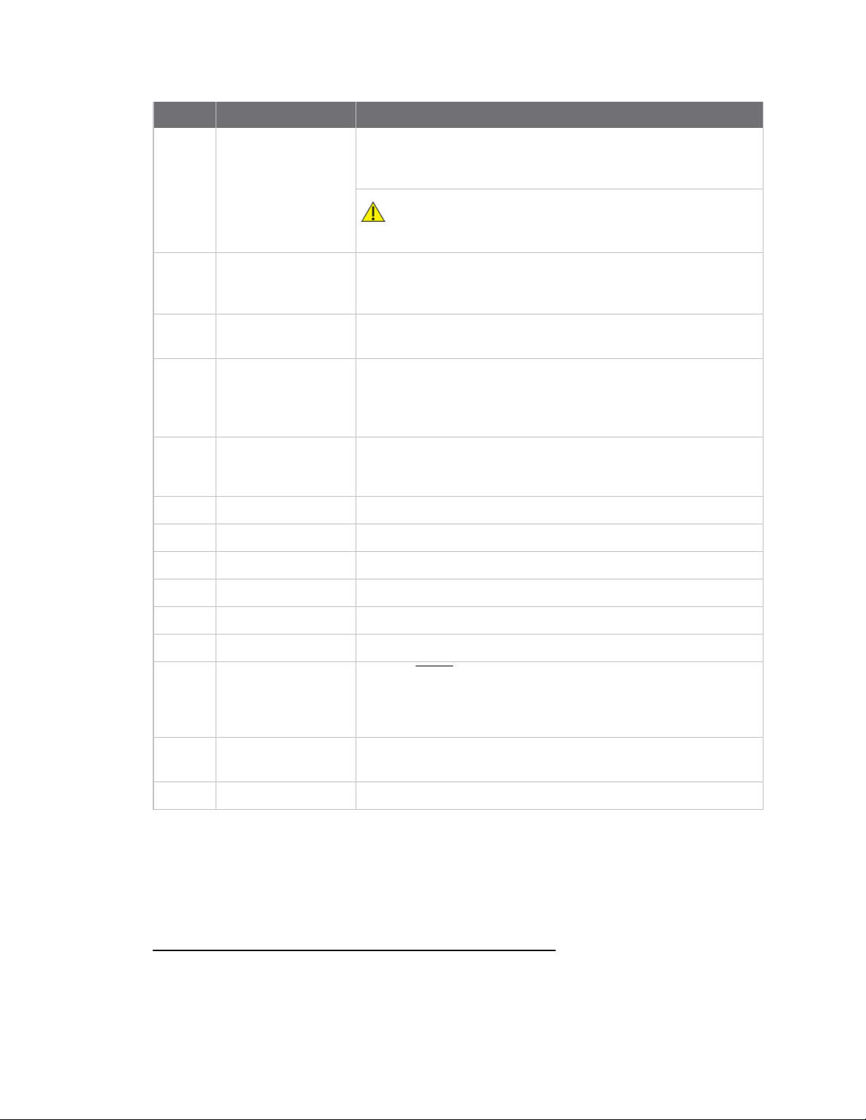
This picture shows the XBee USB development board and the table that follows explains the callouts
in the picture.
Number Item Description
1 Programmingheader Header used to program XBee Programmable devices.
Digi XBee3 Cellular LTE-M Global Smart Modem User Guide
12
Page 13
Getting started with the XBee Smart Modem Development Kit Cellular service
Number Item Description
2 Self power module
3 Current testing Depopulating R31 allows a current probe to be inserted across P6
4 Loopback jumper Populating P8 with a loopback jumper causes serial transmissions
5 DC barrel plug: 6-20V Greater than 500 mA loads require a DC supply for correct
6 LED indicator
7 USB
8 RSSI indicator
Advanced users only—voids the warranty. Depopulate R31 to
power the device using V+ and GND from J2 and J5. You can
connect sense lines to S+ and S- for sensing power supplies.
CAUTION: Voltage is not regulated. Applying the incorrect
voltage can cause fire and serious injury.
terminals. The current though P6/R31 powers the device only.
Other supporting circuitry is powered by a different trace.
both from the device and from the USB to loopback.
operation. Plug in the external power supply prior to the USB
connector to ensure that proper USB communications are not
interrupted.
Yellow: Modem sending serial/UART data to host.
Green: Modem receiving serial/UART data from host.
Red: Associate.
1
9 User buttons Connected to DIO lines for user implementation.
10 Reset button
11 SPI power Connect to the power board from 3.3 V.
12 SPI Only used for surface-mount devices.
13 Indicator LEDs
14 Through-hole XBee
sockets
15 20-pin header Maps to standard through-hole XBee pins.
Cellular service
The XBee Cellular kit includes six months of free cellular service.
1
Powering the board with J2 and J5 without R31 removed can cause shorts if the USB or barrel plug power are
connected. Applying too high a voltage destroys electronic circuitry in the device and other board components
and/or can cause injury.
DS5: ON/SLEEP
DS2: DIO12, the LED illuminates when driven low.
DS3: DIO11, the LED illuminates when driven low.
DS4: DIO4, the LED illuminates when driven low.
Digi XBee3 Cellular LTE-M Global Smart Modem User Guide
13
Page 14

Getting started with the XBee Smart Modem Development Kit Connect the hardware
Connect the hardware
1. The XBee Smart Modem should already be plugged into the XBIB-U-DEV board.
2. The SIMcard should be already be inserted into the XBee Smart Modem. If not, install the
SIMcard into the XBee Smart Modem.
WARNING! Never insert or remove the SIM card while the device is powered!
3. Connect the antennas to the XBee Smart Modem by aligning the U.FL connectors carefully,
then firmly pressing straight down to seat the connector. You should hear a snap when the
antenna attaches correctly. U.FL is fragile and is not designed for multiple insertions, so
exercise caution when connecting or removing the antennas. We recommend using a U.FL
removal tool.
4. Plug the 12 V power supply to the power jack on the development board.
5. Connect the USB cable from a PC to the USB port on the development board. The computer
searches for a driver, which can take a few minutes to install.
Digi XBee3 Cellular LTE-M Global Smart Modem User Guide
14
Page 15
Getting started with the XBee Smart Modem Development Kit Configure the device using XCTU
Configure the device using XCTU
XBee Configuration and Test Utility (XCTU) is a multi-platform program that enables users to interact
with Digi radio frequency (RF) devices through a graphical interface. The application includes built-in
tools that make it easy to set up, configure, and test Digi RF devices.
XCTU does not work directly over an SPI interface.
For instructions on downloading and using XCTU, see the XCTU User Guide.
Note If you are on a macOS computer and encounter problems installing XCTU, see Correct a macOS
Java error.
Add a device
These instructions show you how to add the XBee Smart Modem to XCTU. If XCTU does not find your
serial port, see Cannot find the serial port for the device.
Launch XCTU .
1.
Click the Discover radio modules button .
2.
3. In the Discover radio devices dialog, select the serial ports where you want to look for XBee
modules, and click Next.
4. In the Set port parameters window, maintain the default values and click Finish.
5. As XCTU locates radio modules, they appear in the Discovering radio modules dialog box.
If your module could not be found, XCTU displays the Could not find any radio module dialog
providing possible reasons why the module could not be added.
Digi XBee3 Cellular LTE-M Global Smart Modem User Guide
15
Page 16
Getting started with the XBee Smart Modem Development Kit Configure the device using XCTU
Check for cellular registration and connection
In the following examples, proper cellular network registration and address assignment must occur
successfully. The LED on the development board blinks when the XBee Smart Modem is registered to
the cellular network; see The Associate LED. If the LEDremains solid, registration has not occurred
properly. Registration can take several minutes.
Note Make sure you are in an area with adequate cellular network reception or the XBee Smart
Modem will not make the connection.
In addition to the LED confirmation, you can check the AT commands below in XCTU to check the
registration and connection. To view these commands:
1. Open XCTU and Add a device.
Click the Configuration working mode button.
2.
3. Select a device from the Radio Modules list. XCTU displays the current firmware settings for
that device.
On the Configuration toolbar, click the Default button to load the default values
4.
established by the firmware, and click Yes to confirm.
The relevant commands are:
n AI (Association Indication) reads zero when the device successfully registers to the cellular
network. If it reads 0x23 it is connecting to the Internet; 0x22 means it is registering to the
cellular network.
n MY (Module IPAddress) should display a valid IPaddress. If it reads 0.0.0.0, it has not
registered yet.
Note To search for an ATcommand in XCTU, use the search box.
Update to the latest firmware
Firmware is the program code stored in the device's persistent memory that provides the control
program for the device. Use XCTU to update the firmware.
Click the Configuration working modes button .
1.
2. Select a local XBee module from the Radio Modules list.
Click the Update firmware button .
3.
The Update firmware dialog displays the available and compatible firmware for the selected
XBee module.
4. Select the product family of the XBee module, the function set, and the latest firmware version.
Digi XBee3 Cellular LTE-M Global Smart Modem User Guide
16
Page 17

Getting started with the XBee Smart Modem Development Kit Configure the device using XCTU
5. Click Update. A dialog displays update progress. Click Show details for details of the firmware
update process.
See How to update the firmware of your modules in the XCTU User Guide for more information.
Digi XBee3 Cellular LTE-M Global Smart Modem User Guide
17
Page 18
Getting started with the XBee Smart Modem Development Kit Send an SMS message to a phone
Send an SMS message to a phone
The XBee Smart Modem can send and receive Short Message Service (SMS) transmissions (text
messages) while in Transparent mode. This allows you to send and receive text messages to and from
an SMS capable device such as a mobile phone.
The following table explains the AT commands that you use in this example.
Command Value Description
AP (APIEnable)
IP (IP Protocol)
P#
(DestinationPhone
Number)
TD (Text Delimiter)
PH (Module's SIM
phone number)
1. Ensure that the device is set up correctly with the SIM card installed and the antennas
connected as described in Connect the hardware.
2. Open XCTU and Add a device.
Click the Configuration working mode button.
3.
4. Select a device from the Radio Modules list. XCTU displays the current firmware settings for
that device.
0 Set the device's API mode to Transparent mode.
2 Set the expected transmission mode to SMScommunication.
<Target
phone
number>
D (0x0D)
Read
only
The target phone number that you send to, for example, your
cellular phone. See P# (Destination Phone Number) for instructions
on using this command.
The text delimiter to be used for Transparent mode, as an ASCII hex
code. No information is sent until this character is entered, unless
the maximum number of characters has been reached. Set to zero
to disable text delimiter checking. Set to D for a carriage return.
The value that represents your device's phone number as supplied
by the SIM card. This is used to send text messages to the device
from another cellular device.
To switch to SMS communication, in the IP field, select 2 and click the Write button .
5.
6. To enter your cell phone number, in the P# field, type the <target phone number> and click
the Write button. Type the phone number using only numbers, with no dashes. You can use the
+ prefix if necessary. The target phone number is the phone number you wish to send a text to.
7. In the TD field, type D and click the Write button.
8. Note the number in the PH field; it is the XBee Smart Modem phone number, which you see
when it sends an SMS to your phone.
Digi XBee3 Cellular LTE-M Global Smart Modem User Guide
18
Page 19
Getting started with the XBee Smart Modem Development Kit Send an SMS message to a phone
Click the Consoles working mode button on the toolbar to open a serial console to the
9.
device. For instructions on using the Console, see the AT console topic in the XCTU User Guide.
Click the Open button to open a serial connection to the device.
10.
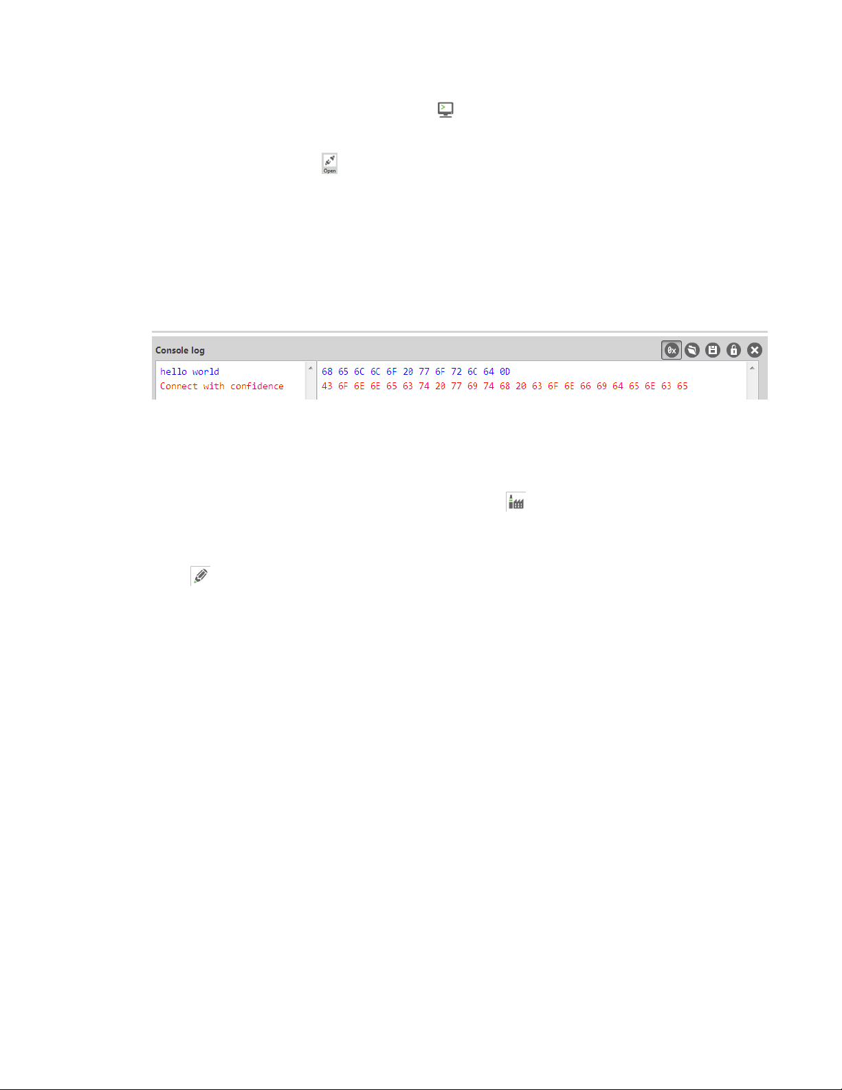
11. Click in the left pane of the Console log, type hello world and press Enter. The XBee Smart
Modem sends the message to the destination phone number set by the P# command.
12. When the phone receives the text, you can see that the sender's phone number matches the
value reported by the XBee Smart Modem with the PH command.
13. On the phone, reply with the text connect with confidence and the XBee Smart Modem
outputs this reply from the UART.
Debugging
If you experience problems with the settings in this example, you can load the default settings in
XCTU:
On the Configuration toolbar, click the Default button to load the default values
1.
established by the firmware, and click Yes to confirm.
2. Factory settings are loaded but not written to the device. To write them, click the Write button
on the toolbar.
Digi XBee3 Cellular LTE-M Global Smart Modem User Guide
19
Page 20
Getting started with the XBee Smart Modem Development Kit Connect to the ELIZA server
Connect to the ELIZA server
You can use the XBee Smart Modem to chat with the ELIZA Therapist Bot. ELIZAis an artificial
intelligence (AI) bot that emulates a therapist and can perform simple conversations.
The following table explains the AT commands that you use in this example.
At command Value Description
IP (IP Protocol) 1 Set the expected transmission mode to TCP
communications.
DL (Destination
Address)
DE (Destination Port) 0x2328 The target port number of the Eliza server.
To communicate with the ELIZA Therapist Bot:
1. Ensure that the device is set up correctly with the SIM card installed and the antennas
connected as described in Connect the hardware.
2. Open XCTU and Add a device.
Click the Configuration working mode button.
3.
4. Select a device from the Radio Modules list. XCTU displays the current firmware settings for
that device.
To switch to TCP communication, in the IP field, select 1 and click the Write button .
5.
6. To enter the destination address of the ELIZATherapist Bot, in the DL field, type 52.43.121.77
and click the Write button.
52.43.121.77 The target IP address of the Eliza server.
7. To enter the destination IP port number, in the DE field, type 2328 and click the Write button.
Click the Consoles working mode button on the toolbar to open a serial console to the
8.
device. For instructions on using the Console, see the AT console topic in the XCTU User Guide.
Click the Open button to open a serial connection to the device.
9.
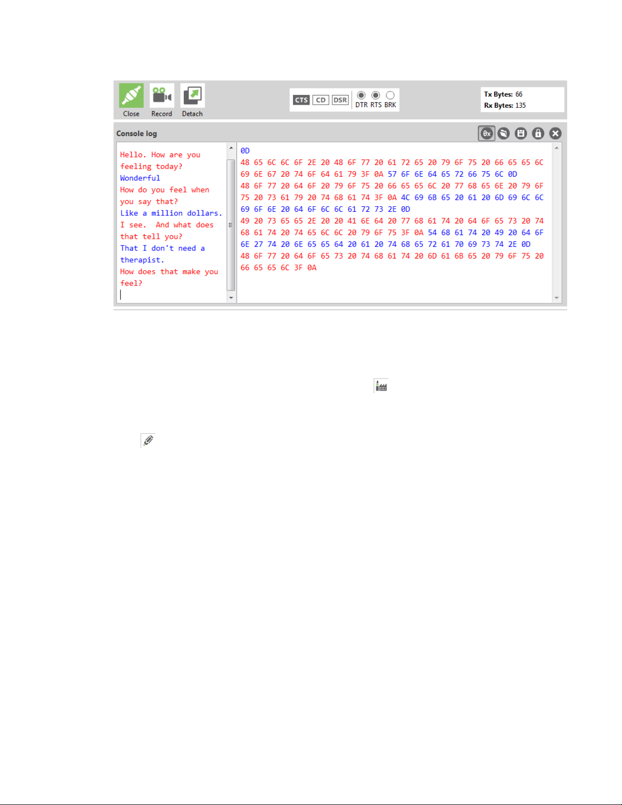
10. Click in the left pane of the Console log, then type in the Console to talk to the ELIZA Therapist
Bot. The following screenshot provides an example of this chat.
Digi XBee3 Cellular LTE-M Global Smart Modem User Guide
20
Page 21
Getting started with the XBee Smart Modem Development Kit Connect to the ELIZA server
Debugging
If you experience problems with the settings in this example, you can load the default settings in
XCTU:
On the Configuration toolbar, click the Default button to load the default values
1.
established by the firmware, and click Yes to confirm.
2. Factory settings are loaded but not written to the device. To write them, click the Write button
on the toolbar.
Digi XBee3 Cellular LTE-M Global Smart Modem User Guide
21
Page 22
Getting started with the XBee Smart Modem Development Kit Connect to the echo server
Connect to the echo server
This server echoes back the messages you type.
The following table explains the AT commands that you use in this example.
At
command Value Description
IP (IP
Protocol)
TD
(Text
Delimiter)
DL
(Destination
Address)
DE
(Destination
Port)
To communicate with the echo server:
1. Ensure that the device is set up correctly with the SIM card installed and the antennas
connected as described in Connect the hardware.
2. Open XCTU and Add a device.
Click the Configuration working mode button.
3.
4. Select a device from the Radio Modules list. XCTU displays the current firmware settings for
that device.
1 Set the expected transmission mode to TCP communications.
D (0x0D)
52.43.121.77 The target IPaddress of the echo server.
0x2329 The target port number of the echo server.
The text delimiter to be used for Transparent mode, as an ASCII hex
code. No information is sent until this character is entered, unless the
maximum number of characters has been reached. Set to zero to
disable text delimiter checking. Set to D for a carriage return.
To switch to TCP communication, in the IP field, select 1 and click the Write button .
5.
6. To enable the XBee Smart Modem to recognize carriage return as a message delimiter, in the
TD field, type D and click the Write button.
7. To enter the destination address of the echo server, in the DL field, type 52.43.121.77 and click
the Write button.
8. To enter the destination IP port number, in the DE field, type 2329 and click the Write button.
Digi XBee3 Cellular LTE-M Global Smart Modem User Guide
22
Page 23
Getting started with the XBee Smart Modem Development Kit Connect to the echo server
Click the Consoles working mode button on the toolbar to open a serial console to the
9.
device. For instructions on using the Console, see the AT console topic in the XCTU User Guide.
Click the Open button to open a serial connection to the device.
10.
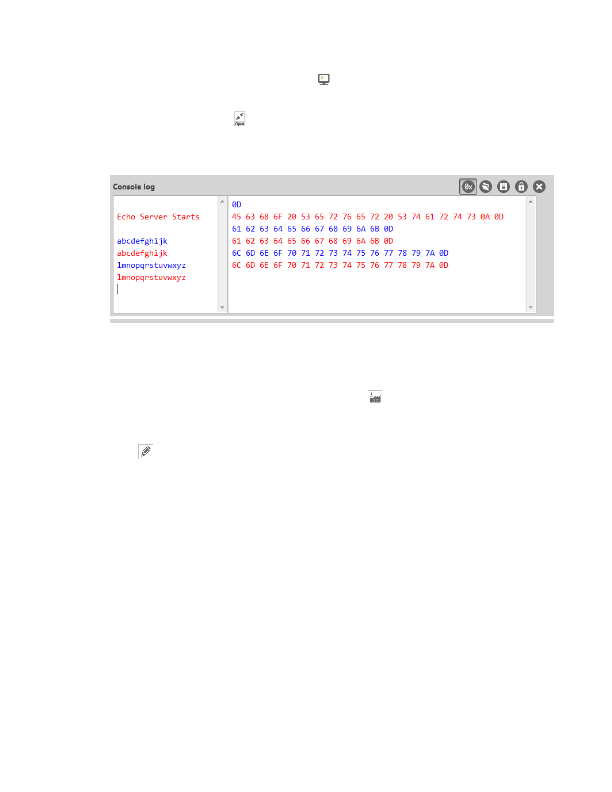
11. Click in the left pane of the Console log, then type in the Console to talk to the echo server.
The following screenshot provides an example of this chat.
Debugging
If you experience problems with the settings in this example, you can load the default settings in
XCTU:
On the Configuration toolbar, click the Default button to load the default values
1.
established by the firmware, and click Yes to confirm.
2. Factory settings are loaded but not written to the device. To write them, click the Write button
on the toolbar.
Digi XBee3 Cellular LTE-M Global Smart Modem User Guide
23
Page 24
Getting started with the XBee Smart Modem Development Kit Connect to the Daytime server
Connect to the Daytime server
The Daytime server reports the current Coordinated Universal Time (UTC) value responding to any
user input.
The following table explains the AT commands that you use in this example.
At
command Value Description
IP (IP
Protocol)
DL
(Destination
Address)
DE
(Destination
Port)
TD (Text
Delimiter)
To communicate with the Daytime server:
1. Ensure that the device is set up correctly with the SIM card installed and the antennas
connected as described in Connect the hardware.
2. Open XCTU and Add a device.
Click the Configuration working mode button.
3.
4. Select a device from the Radio Modules list. XCTU displays the current firmware settings for
that device.
1 Set the expected transmission mode to TCP communications.
52.43.121.77 The target IP of the Daytime server.
0x232A The target port number of the Daytime server.
0
The text delimiter to be used for Transparent mode, as an ASCII hex
code. No information is sent until this character is entered, unless the
maximum number of characters has been reached. Set to zero to
disable text delimiter checking.
To switch to TCP communication, in the IP field, select 1 and click the Write button .
5.
6. To enter the destination address of the daytime server, in the DL field, type 52.43.121.77 and
click the Write button.
7. To enter the destination IP port number, in the DE field, type 232A and click the Write button.
8. To disable text delimiter checking, in the TD field, type 0 and click the Write button.
Click the Consoles working mode button on the toolbar to open a serial console to the
9.
device. For instructions on using the Console, see the AT console topic in the XCTU User Guide.
Digi XBee3 Cellular LTE-M Global Smart Modem User Guide
24
Page 25
Getting started with the XBee Smart Modem Development Kit Connect to the Daytime server
Click the Open button to open a serial connection to the device.
10.
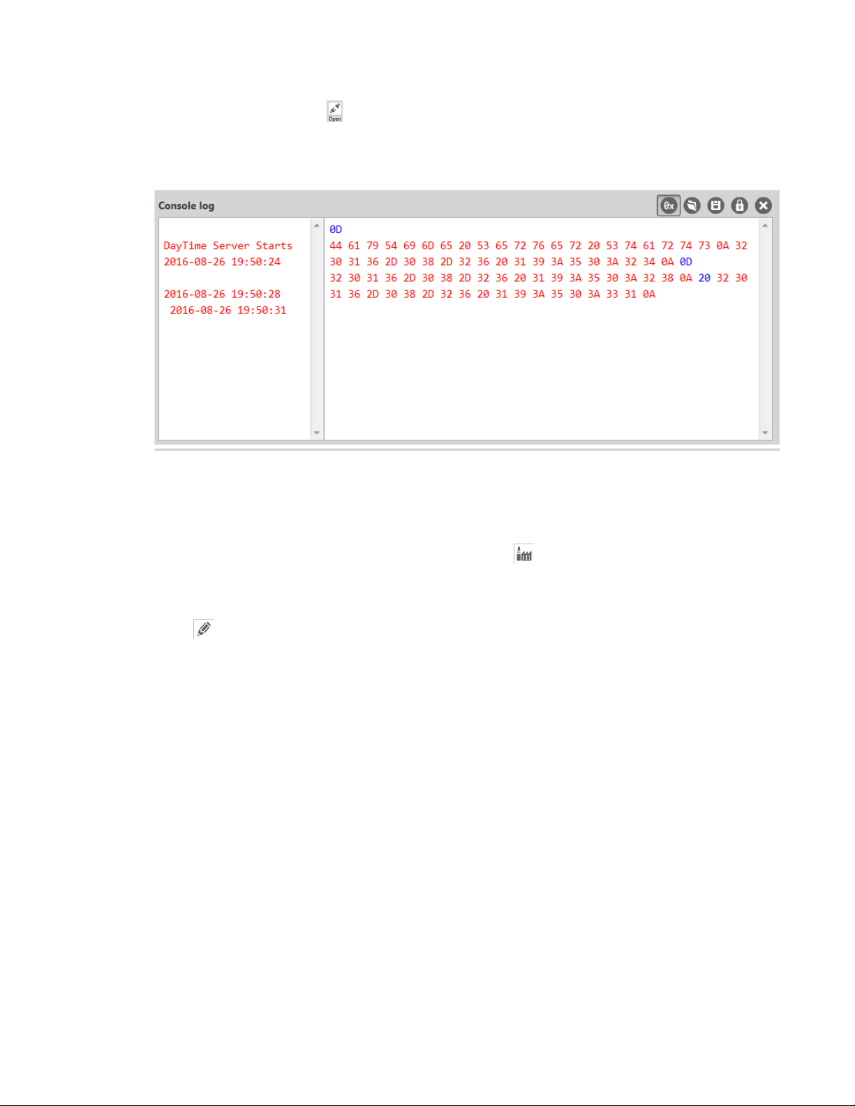
11. Click in the left pane of the Console log, then type in the Console to query the Daytime server.
The following screenshot provides an example of this chat.
Debugging
If you experience problems with the settings in this example, you can load the default settings in
XCTU:
On the Configuration toolbar, click the Default button to load the default values
1.
established by the firmware, and click Yes to confirm.
2. Factory settings are loaded but not written to the device. To write them, click the Write button
on the toolbar.
Digi XBee3 Cellular LTE-M Global Smart Modem User Guide
25
Page 26
Getting started with the XBee Smart Modem Development Kit Connect to a TCP/IP address
Connect to a TCP/IP address
The XBee Smart Modem can send and receive TCP messages while in Transparent mode; see
Transparent operating mode.
You can use this example as a template for sending and receiving data from a user. The following table
explains the AT commands that you use in this example.
Command Value Description
IP (IP
Protocol)
DL
(Destination
IPAddress)
DE
(Destination
Port)
To connect to a TCP/IP address:
1. Ensure that the device is set up correctly with the SIM card installed and the antennas
connected as described in Connect the hardware.
2. Open XCTU and Add a device.
Click the Configuration working mode button.
3.
4. Select a device from the Radio Modules list. XCTU displays the current firmware settings for
that device.
1 Set the expected transmission mode to TCPcommunication.
<Target
IPaddress>
<Target
portnumber>
The target IP address that you send and receive from. For example, a
data logging server’s IP address that you want to send
measurements to.
The target port number that the device sends the transmission to.
This is represented as a hexadecimal value.
In the IP field, select 1 and click the Write button .
5.
6. In the DL field, type the <target IP address> and click the Write button. The target IP address
is the IPaddress that you send and receive from.
7. In the DE field, type the <target port number>, converted to hexadecimal, and click the Write
button.
8. Exit Command mode; see Exit Command mode.
After exiting Command mode, any UART data sent to the device is sent to the destination IP address
and port number after the RO (Packetization Timeout) occurs.
Digi XBee3 Cellular LTE-M Global Smart Modem User Guide
26
Page 27

Getting started with the XBee Smart Modem Development Kit Connect to a TCP/IP address
Debugging
If you experience problems with the settings in this example, you can load the default settings in
XCTU:
On the Configuration toolbar, click the Default button to load the default values
1.
established by the firmware, and click Yes to confirm.
2. Factory settings are loaded but not written to the device. To write them, click the Write button
on the toolbar.
Digi XBee3 Cellular LTE-M Global Smart Modem User Guide
27
Page 28

Getting started with the XBee Smart Modem Development Kit Perform a (GET) HTTP request
Perform a (GET) HTTP request
You can use the XBee Smart Modem to perform a GET Hypertext Transfer Protocol (HTTP) request
using XCTU. This example uses http://httpbin.org/ as the target website that responds to the HTTP
request.
To perform a GETrequest:
1. Ensure that the device is set up correctly with the SIM card installed and the antennas
connected as described in Connect the hardware.
2. Open XCTU and Add a device.
Click the Configuration working mode button.
3.
4. Select a device from the Radio Modules list. XCTU displays the current firmware settings for
that device.
5. To enter the destination address of the target website, in the DL field, type httpbin.org and
click the Write button .
6. To enter the HTTP request port number, in the DE field, type 50 and click the Write button.
Hexadecimal 50 is 80 in decimal.
7. To switch to TCP communication, in the IP field, select 1 and click the Write button.
8. To move into Transparent mode, in the APfield, select 0 and click the Write button.
9. Wait for the AI (Association Indication) value to change to 0 (Connected to the Internet).
Click the Consoles working mode button on the toolbar.
10.
From the AT console, click the Add new packet button in the Send packets dialog. The
11.
Add new packet dialog appears.
12. Enter the name of the data packet.
13. Type the following data in the ASCII input tab:
GET /ip HTTP/1.1
Host: httpbin.org
14. Click the HEX input tab and add 0A (zero A) after each 0D (zero D), and add an additional 0D 0A
at the end of the message body. For example, copy and past the following text into the HEX
input tab:
47 45 54 20 2F 69 70 20 48 54 54 50 2F 31 2E 31 0D 0A 48 6F 73 74 3A 20 68 74 74 70 62 69 6E
2E 6F 72 67 0D 0A 0D 0A
Note The HTTP protocol requires an empty line (a line with nothing preceding the CRLF) to terminate
the request.
15. Click Add packet.
Click the Open button .
16.
Digi XBee3 Cellular LTE-M Global Smart Modem User Guide
28
Page 29

Getting started with the XBee Smart Modem Development Kit Perform a (GET) HTTP request
17. Click Send selected packet.
18. A GETHTTP response from httpbin.org appears in the Console log.
Debugging
If you experience problems with the settings in this example, you can load the default settings in
XCTU:
On the Configuration toolbar, click the Default button to load the default values
1.
established by the firmware, and click Yes to confirm.
2. Factory settings are loaded but not written to the device. To write them, click the Write button
on the toolbar.
Digi XBee3 Cellular LTE-M Global Smart Modem User Guide
29
Page 30

Getting started with the XBee Smart Modem Development Kit Get started with MQTT
Get started with MQTT
MQ Telemetry Transport (MQTT) is a messaging protocol that is ideal for the Internet of Things (IoT)
due to a light footprint and its use of the publish-subscribe model. In this model, a client connects to a
broker, a server machine responsible for receiving all messages, filtering them, and then sending
messages to the appropriate clients.
The first two MQTTexamples do not involve the XBee Smart Modem. They demonstrate using the
MQTTlibraries because those libraries are required for Use MQTT over the XBee Cellular Modem with
a PC.
The examples in this guide assume:
n Some knowledge of Python.
n An integrated development environment (IDE)such as PyCharm, IDLE or something similar.
The examples require:
n An XBee Smart Modem.
n A compatible development board, such as the XBIB-U.
n XCTU. See Configure the device using XCTU.
n That you install Python on your computer. You can download Python from:
https://www.python.org/downloads/.
n That you install the pyserial and paho-mqtt libraries to the Python environment. If you use
Python 2, install these libraries from the command line with pip install pyserial and pip
install paho-mqtt. If you use Python 3, use pip3 install pyserial and pip3 install paho-mqtt.
n The full MQTT library source code, which includes examples and tests, which is available in the
paho-mqtt github repository at https://github.com/eclipse/paho.mqtt.python. To download this
repository you must have Git installed.
Example: MQTT connect
This example provides insight into the structure of packets in MQTT as well as the interaction
between the client and broker. MQTT uses different packets to accomplish tasks such as connecting,
subscribing, and publishing. You can use XCTU to perform a basic example of sending a broker a
connect packet and receiving the response from the server, without requiring any coding. This is a
good way to see how the client interacts with the broker and what a packet looks like. The following
table is an example connect packet:
Description Hex value
CONNECT packet fixed header
byte 1 Control packet type 0x10
byte 2 Remaining length 0x10
CONNECT packet variable header
Protocol name
Digi XBee3 Cellular LTE-M Global Smart Modem User Guide
30
Page 31

Getting started with the XBee Smart Modem Development Kit Get started with MQTT
Description Hex value
byte 1 Length MSB (0) 0x00
byte 2 Length LSB (4) 0x04
byte 3 (M) 0x4D
byte 4 (Q) 0x51
byte 5 (T) 0x54
byte 6 (T) 0x54
Protocol level
byte 7 Level (4) 0x04
Connect flags
byte 8
Keep alive
byte 9 Keep Alive MSB (0) 0X00
byte 10 Keep Alive LSB (60) 0X3C
Client ID
byte 11 Length MSB (0) 0x00
byte 12 Length LSB (4) 0x04
byte 13 (D) 0x44
byte 14 (I) 0x49
byte 15 (G) 0x47
byte 16 (I) 0x49
The following table describes the fields in the packet:
Fieldname Description
ProtocolName The connect packet starts with the protocol name, which is MQTT. The length of
CONNECT flags byte, see the table below for the bits.
the protocol name (in bytes) is immediately before the name itself.
0X02
ProtocolLevel Refers to the version of MQTT in use, in this case a value of 4 indicates MQTT
version 3.1.1.
Connect Flags Indicate certain aspects of the packet. For simplicity, this example only sets the
Clean Session flag, which indicates to the client and broker to discard any previous
session and start a new one.
Keep Alive How often the client pings the broker to keep the connection alive; in this example
it is set to 60 seconds.
Digi XBee3 Cellular LTE-M Global Smart Modem User Guide
31
Page 32

Getting started with the XBee Smart Modem Development Kit Get started with MQTT
Fieldname Description
Client ID The length of the ID (in bytes) precedes the ID itself. Each client connecting to a
broker must have a unique client ID. In the example, the ID is DIGI. When using the
Paho MQTT Python libraries, a random alphanumeric ID is generated if you do not
specify an ID.
The following table provides the CONNECT flag bits from byte 8, the CONNECT flags byte.
CONNECT Flag Bit(s) Bit 7 Bit 6 Bit 5 Bit 4 Bit 3 Bit 2 Bit 1 Bit 0
User name flag 0
Password flag 0
Will retain 0
Will QoS 0 0
Will flag 0
Clean session 1
Reserved 0
Send a connect packet
Now that you know what a connect packet looks like, you can send a connect packet to a broker and
view the response. Open XCTU and click the Configuration working mode button.
1. Ensure that the device is set up correctly with the SIM card installed and the antennas
connected as described in Connect the hardware.
Open XCTU and click the Configuration working mode button.
2.
3. Add the XBee Smart Modem to XCTU; see Add a device.
4. Select a device from the Radio Modules list. XCTU displays the current firmware settings for
that device.
5. In the APfield, set Transparent Mode to [0] if it is not already and click the Write button.
6. In the DL field, type the IP address of the broker you wish to use. This example uses
198.41.30.241, which is the IP address for m2m.eclipse.org, a public MQTT broker.
7. In the DE field, type 75B and set the port that the broker uses. This example uses 75B, because
the default MQTT port is 1883 (0x75B).
8. Once you have entered the required values, click the Write button to write the changes to the
XBee Smart Modem.
Digi XBee3 Cellular LTE-M Global Smart Modem User Guide
32
Page 33

Getting started with the XBee Smart Modem Development Kit Get started with MQTT
Click the Consoles working mode button on the toolbar to open a serial console to the
9.
device. For instructions on using the Console, see the AT console topic in the XCTU User Guide.
Click the Open button to open a serial connection to the device.
10.
From the AT console, click the Add new packet button in the Send packets dialog. The
11.
Add new packet dialog appears.
12. Enter the name of the data packet. Name the packet connect_frame or something similar.
13. Click the HEX input tab and type the following (these values are the same values from the
table in Example: MQTT connect):
10 10 00 04 4D 51 54 54 04 02 00 3C 00 04 44 49 47 49
14. Click Add packet. The new packet appears in the Send packets list.
15. Click the packet in the Send packets list.
16. Click Send selected packet.
17. A CONNACK packet response from the broker appears in the Console log. This is a connection
acknowledgment; a successful response should look like this:
Digi XBee3 Cellular LTE-M Global Smart Modem User Guide
33
Page 34

Getting started with the XBee Smart Modem Development Kit Get started with MQTT
You can verify the response from the broker as a CONNACK by comparing it to the structure of a
CONNACK packet in the MQTT documentation, which is available at http://docs.oasis-
open.org/mqtt/mqtt/v3.1.1/os/mqtt-v3.1.1-os.html#_Toc398718081).
Example: send messages (publish) with MQTT
A basic Python example of a node publishing (sending) a message is:
mqttc = mqtt.Client("digitest") # Create instance of client with client ID
“digitest”
mqttc.connect("m2m.eclipse.org", 1883) # Connect to (broker, port, keepalivetime)
mqttc.loop_start() # Start networking daemon
mqttc.publish("digitest/test1", "Hello, World!") # Publish message to “digitest
/test1” topic
mqttc.loop_stop() # Kill networking daemon
Note You can easily copy and paste code from the online version of this Guide. Use caution with the
PDF version, as it may not maintain essential indentations.
This example imports the MQTT library, allowing you to use the MQTT protocol via APIs in the library,
such as the connect(), subscribe(), and publish() methods.
The second line creates an instance of the client, named mqttc. The client ID is the argument you
passed in: digitest (this is optional).
In line 3, the client connects to a public broker, in this case m2m.eclipse.org, on port 1883 (the default
MQTT port, or 8883 for MQTT over SSL). There are many publicly available brokers available, you can
find a list of them here: https://github.com/mqtt/mqtt.github.io/wiki/brokers.
Line 4 starts the networking daemon with client.loop_start() to handle the background
network/data tasks.
Finally, the client publishes its message Hello, World! to the broker under the topic
digitest/backlog/test1. Any nodes (devices, phones, computers, even microcontrollers) subscribed to
that same topic on the same broker receive the message.
Once no more messages need to be published, the last line stops the network daemon with
client.loop_stop().
Example: receive messages (subscribe) with MQTT
This example describes how a client would receive messages from within a specific topic on the
broker:
import paho.mqtt.client as mqtt
def on_connect(client, userdata, flags, rc): # The callback for when the client
connects to the broker
print("Connected with result code {0}".format(str(rc))) # Print result of
connection attempt
client.subscribe("digitest/test1") # Subscribe to the topic
“digitest/test1”, receive any messages published on it
def on_message(client, userdata, msg): # The callback for when a PUBLISH message
is received from the server.
print("Message received-> " + msg.topic + " " + str(msg.payload)) # Print a
Digi XBee3 Cellular LTE-M Global Smart Modem User Guide
34
Page 35

Getting started with the XBee Smart Modem Development Kit Get started with MQTT
received msg
client = mqtt.Client("digi_mqtt_test") # Create instance of client with client
ID “digi_mqtt_test”
client.on_connect = on_connect # Define callback function for successful
connection
client.on_message = on_message # Define callback function for receipt of a
message
# client.connect("m2m.eclipse.org", 1883, 60) # Connect to (broker, port,
keepalive-time)
client.connect('127.0.0.1', 17300)
client.loop_forever() # Start networking daemon
Note You can easily copy and paste code from the online version of this Guide. Use caution with the
PDF version, as it may not maintain essential indentations.
The first line imports the library functions for MQTT.
The functions on_connect and on_message are callback functions which are automatically called by
the client upon connection to the broker and upon receiving a message, respectively.
The on_connect function prints the result of the connection attempt, and performs the subscription.
It is wise to do this in the callback function as it guarantees the attempt to subscribe happens only
after the client is connected to the broker.
The on_message function prints the received message when it comes in, as well as the topic it was
published under.
In the body of the code, we:
n Instantiate a client object with the client ID digi_mqtt_test
n Define the callback functions to use upon connection and upon message receipt
n Connect to an MQTT broker at m2m.eclipse.org, on port 1883 (the default MQTT port, or 8883
for MQTT over SSL) with a keepalive of 60 seconds (this is how often the client pings the broker
to keep the connection alive).
The last line starts a network daemon that runs in the background and handles data transactions and
messages, as well as keeping the socket open, until the script ends.
Use MQTT over the XBee Cellular Modem with a PC
To use this MQTT library over an XBee Smart Modem, you need a basic proxy that transfers a payload
received via the MQTT client’s socket to the serial or COM port that the XBee Smart Modem is active
on, as well as the reverse; transfer of a payload received on the XBee Smart Modem’s serial or COM
port to the socket of the MQTT client. This is simplest with the XBee Smart Modem in Transparent
mode, as it does not require code to parse or create API frames, and not using API frames means
there is no need for them to be queued for processing.
1. To put the XBee Cellular Modem in Transparent mode, set AP to 0.
2. Set DL to the IP address of the broker you want to use.
3. Set DE to the port to use, the default is 1883 (0x75B). This sets the XBee Smart Modem to
communicate directly with the broker, and can be performed in XCTU as described in Example:
MQTT connect.
4. You can make the proxy with a dual-threaded Python script, a simple version follows:
Digi XBee3 Cellular LTE-M Global Smart Modem User Guide
35
Page 36

Getting started with the XBee Smart Modem Development Kit Get started with MQTT
import threading
import serial
import socket
def setup():
"""
This function sets up the variables needed, including the serial port,
and it's speed/port settings, listening socket, and localhost adddress.
"""
global clisock, cliaddr, svrsock, ser
# Change this to the COM port your XBee Cellular module is using. On
# Linux, this will be /dev/ttyUSB#
comport = 'COM44'
# This is the default serial communication speed of the XBee Cellular
# module
comspeed = 115200
buffer_size = 4096 # Default receive size in bytes
debug_on = 0 # Enables printing of debug messages
toval = None # Timeout value for serial port below
# Serial port object for XBCell modem
ser = serial.Serial(comport,comspeed,timeout=toval)
# Listening socket (accepts incoming connection)
svrsock = socket.socket(socket.AF_INET,socket.SOCK_STREAM)
# Allow address reuse on socket (eliminates some restart errors)
svrsock.setsockopt(socket.SOL_SOCKET, socket.SO_REUSEADDR, 1)
clisock = None
cliaddr = None # These are first defined before thread creation
addrtuple = ('127.0.0.1', 17300) # Address tuple for localhost
# Binds server socket to localhost (allows client program connection)
svrsock.bind(addrtuple)
svrsock.listen(1) # Allow (1) connection
def ComReaderThread():
"""
This thread listens on the defined serial port object ('ser') for data
from the modem, and upon receipt, sends it out to the client over the
client socket ('clisock').
"""
global clisock
while (1):
resp = ser.read() ## Read any available data from serial port
print("Received {} bytes from modem.".format(len(resp)))
clisock.sendall(resp) # Send RXd data out on client socket
print("Sent {} byte payload out socket to client.".format(len(resp)))
def SockReaderThread():
"""
This thread listens to the MQTT client's socket and upon receiving a
payload, it sends this data out on the defined serial port ('ser') to the
modem for transmission.
"""
global clisock
while (1):
data = clisock.recv(4096) # RX data from client socket
Digi XBee3 Cellular LTE-M Global Smart Modem User Guide
36
Page 37

Getting started with the XBee Smart Modem Development Kit Get started with MQTT
# If the RECV call returns 0 bytes, the socket has closed
if (len(data) == 0):
print("ERROR - socket has closed. Exiting socket reader thread.")
return 1 # Exit the thread to avoid a loop of 0-byte receptions
else:
print("Received {} bytes from client via socket.".format(len(data)))
print("Sending payload to modem...")
bytes_wr = ser.write(data) # Write payload to modem via UART/serial
print("Wrote {} bytes to modem".format(bytes_wr))
def main():
setup() # Setup the serial port and socket
global clisock, svrsock
if (not clisock): # Accept a connection on 'svrsock' to open 'clisock'
print("Awaiting ACCEPT on server sock...")
(clisock,cliaddr) = svrsock.accept() # Accept an incoming connection
print("Connection accepted on socket")
# Make thread for ComReader
comthread = threading.Thread(target=ComReaderThread)
comthread.start() # Start the thread
# Make thread for SockReader
sockthread = threading.Thread(target=SockReaderThread)
sockthread.start() # Start the thread
main()
Note This script is a general TCP-UART proxy, and can be used for other applications or scripts that
use the TCP protocol. Its functionality is not limited to MQTT.
Note You can easily copy and paste code from the online version of this Guide. Use caution with the
PDF version, as it may not maintain essential indentations.
This proxy script waits for an incoming connection on localhost (127.0.0.1), on port 17300. After
accepting a connection, and creating a socket for that connection (clisock), it creates two threads,
one that reads the serial or COM port that the XBee Smart Modem is connected to, and one that
reads the socket (clisock), that the MQTT client is connected to.
With:
n The proxy script running
n The MQTT client connected to the proxy script via localhost (127.0.0.1)
n The XBee Smart Modem connected to the machine via USB and properly powered
n AP, DL, and DE set correctly
the proxy acts as an intermediary between the MQTT client and the XBee Smart Modem, allowing the
MQTT client to use the data connection provided by the device.
Think of the proxy script as a translator between the MQTT client and the XBee Smart Modem. The
following figure shows the basic operation.
Digi XBee3 Cellular LTE-M Global Smart Modem User Guide
37
Page 38

Getting started with the XBee Smart Modem Development Kit Get started with MQTT
The thread that reads the serial port forwards any data received onward to the client socket, and the
thread reading the client socket forwards any data received onward to the serial port. This is
represented in the figure above.
The proxy script needs to be running before running an MQTT publish or subscribe script.
1. With the proxy script running, run the subscribe example from Example: receive messages
(subscribe) with MQTT, but change the connect line from client.connect("m2m.eclipse.org",
1883, 60) to client.connect("127.0.0.1", port=17300, keepalive=20). This connects the
MQTT client to the proxy script, which in turn connects to a broker via the XBee Smart
Modem’s internet connection.
2. Run the publish example from Example: send messages (publish) with MQTT in a third Python
instance (while the publish script is running you will have three Python scripts running at the
same time).
The publish script runs over your computer’s normal internet connection, and does not use the XBee
Smart Modem. You are able to see your published message appear in the subscribe script’s output
once it is received from the broker via the XBee Smart Modem. If you watch the output of the proxy
script during this process you can see the receptions and transmissions taking place.
The proxy script must be running before you run the subscribe and publish scripts. If you stop the
subscribe script, the socket closes, and the proxy script shows an error. If you try to start the proxy
script after starting the subscribe script, you may also see a socket error. To avoid these errors, it is
best to start the scripts in the correct order: proxy, then subscribe, then publish.
Digi XBee3 Cellular LTE-M Global Smart Modem User Guide
38
Page 39

Getting started with the XBee Smart Modem Development Kit Get started with CoAP
Get started with CoAP
Constrained Application Protocol (CoAP) is based on UDP connection and consumes low power to
deliver similar functionality to HTTP. This guide contains information about sending GET, POST, PUT
and DELETE operations by using the Coap Protocol with XCTU and Python code working with the XBee
Smart Modem and Coapthon library (Python 2.7 only).
The Internet Engineering Task Force describes CoAP as:
The protocol is designed for machine-to-machine (M2M) applications such as smart energy and
building automation. CoAP provides a request/response interaction model between application
endpoints, supports built-in discovery of services and resources, and includes key concepts of
the Web such as URIs and Internet media types. CoAP is designed to easily interface with HTTP
for integration with the Web while meeting specialized requirements such as multicast
support, very low overhead, and simplicity for constrained environments (source).
CoAP terms
When describing CoAP, we use the following terms:
Term Meaning
Method COAP's method action is similar to the HTTP method. This guide discusses the GET,
POST, PUT and DELETE methods. With these methods, the XBee Smart Modem can
transport data and requests.
URI URI is a string of characters that identifies a resource served at the server.
Token Atoken is an identifier of a message. The client uses the token to verify if the received
message is the correct response to its query.
Payload The message payload is associated with the POST and PUT methods. It specifies the
data to be posted or put to the URI resource
MessageID The message ID is also an identifier of a message. The client matches the message ID
between the response and query.
CoAP quick start example
The following diagram shows the message format for the CoAP protocol; see ISSN: 2070-1721 for
details:
This is an example GET request:
44 01 C4 09 74 65 73 74 B7 65 78 61 6D 70 6C 65
Digi XBee3 Cellular LTE-M Global Smart Modem User Guide
39
Page 40

Getting started with the XBee Smart Modem Development Kit Get started with CoAP
The following table describes the fields in the GETrequest.
Field HEX Bits Meaning
Ver 44 01 Version 01, which is mandatory here.
T 00 Type 0: confirmable.
TKL 0100 Token length: 4.
Code 01 000 00001 Code: 0.01, which indicates the GET method.
Message ID C4 09 2 Bytes equal
to hex at left
Token 74 65 73 74 4 Bytes equal
to hex at left
Option delta B7 1011 Delta option: 11 indicates the option data is Uri-Path.
Optionlength 0111 Delta length: 7 indicates there are 7 bytes of data
Option value 65 78 61 6D
70 6C 65
7 Bytes equal
to hex at left
Message ID. The response message will have the
same ID. This can help out identification.
Token. The response message will have the same
token. This can help out identification.
following as a part of this delta option.
Example.
Configure the device
1. Ensure that the device is set up correctly with the SIM card installed and the antennas
connected as described in Connect the hardware.
Open XCTU and click the Configuration working mode button.
2.
3. Add the XBee Smart Modem to XCTU; see Add a device.
4. Select a device from the Radio Modules list. XCTU displays the current firmware settings for
that device.
To switch to UDPcommunication, in the IP field, select 0 and click the Write button .
5.
6. To set the target IP address that the XBee Smart Modem will talk to, in the DL field type
52.43.121.77and click the Write button . A CoAP server is publicly available at address
52.43.121.77.
7. To set the XBee Smart Modem to send data to port 5683 in decimal, in the DEfield, type 1633
and click the Write button.
8. To move into Transparent mode, in the APfield, select 0 and click the Write button.
9. Wait for the AI (Association Indication) value to change to 0 (Connected to the Internet). You
can click Read to get an update on the AI value.
Example: manually perform a CoAPrequest
Follow the steps in Configure the device prior to this example. This example performs the CoAP
GETrequest:
Digi XBee3 Cellular LTE-M Global Smart Modem User Guide
40
Page 41

Getting started with the XBee Smart Modem Development Kit Get started with CoAP
n Method: GET
n URI: example
n Given message token: test
Click the Consoles working mode button on the toolbar to add a customized packet.
1.
From the AT console, click the Add new packet button in the Send packets dialog. The
2.
Add new packet dialog appears.
3. Click the HEX tab and type the name of the data packet: GET_EXAMPLE.
4. Copy and past the following text into the HEX input tab:
44 01 C4 09 74 65 73 74 B7 65 78 61 6D 70 6C 65
This is the CoAP protocol message decomposed by bytes to perform a GET request on an
example URI with a token test.
5. Click Add packet.
Click the Open button .
6.
7. Click Send selected packet. The message is sent to the public CoAP server configured in
Configure the device. A response appears in the Console log. Blue text is the query, red text is
the response.
The payload is Get to uri: example, which specifies that this is a successful CoAP GET to URI end
example, which was specified in the query.
Click the Close button to terminate the serial connection.
Example: use Python to generate a CoAP message
This example illustrates how the CoAP protocol can perform GET/POST/PUT/DELETE requests
similarly to the HTTP protocol and how to do this using the XBee Smart Modem. In this example, the
XBee Smart Modem talks to a CoAP Digi Server. You can use this client code to provide an abstract
wrapper to generate a CoAP message that commands the XBee Smart Modem to talk to the remote
CoAP server.
Note It is crucial to configure the XBee Smart Modem settings. See Configure the device and follow
the steps. You can target the IP address to a different CoAP public server.
1. Install Python 2.7. The Installation guide is located at: https://www.python.org/downloads/.
2. Download and install the Coapthon library in the python environment from
https://pypi.python.org/pypi/CoAPthon.
3. Download these two .txt files: Coap.txt and CoapParser.txt. After you download them, open the
files in a text editor and save them as .py files.
4. In the folder that you place the Coap.py and CoapParser.py files, press Shift + right-click and
then click Open command window.
5. At the command prompt, type python Coap.py and press Enter to run the program.
Digi XBee3 Cellular LTE-M Global Smart Modem User Guide
41
Page 42

Getting started with the XBee Smart Modem Development Kit Get started with CoAP
6. Type the USB port number that the XBee Smart Modem is connected to and press Enter. Only
the port number is required, so if the port is COM19, type 19.
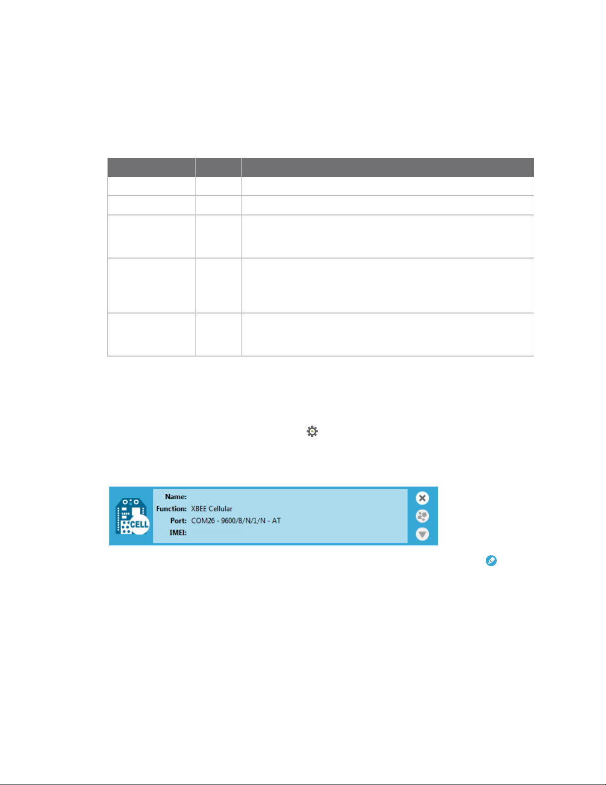
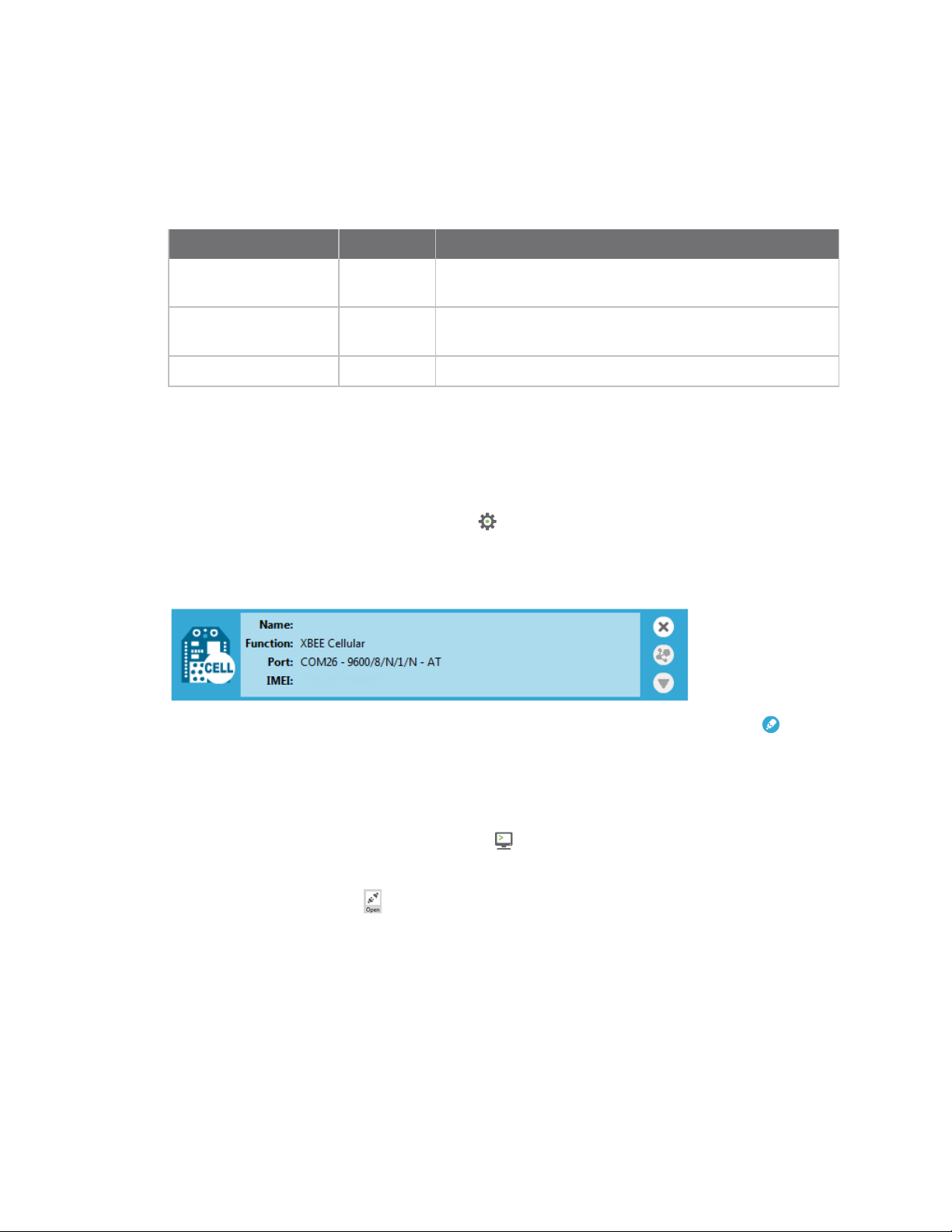
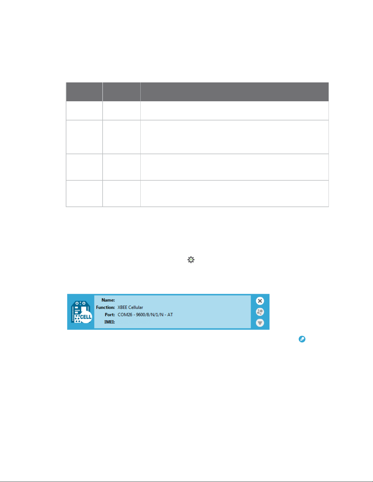
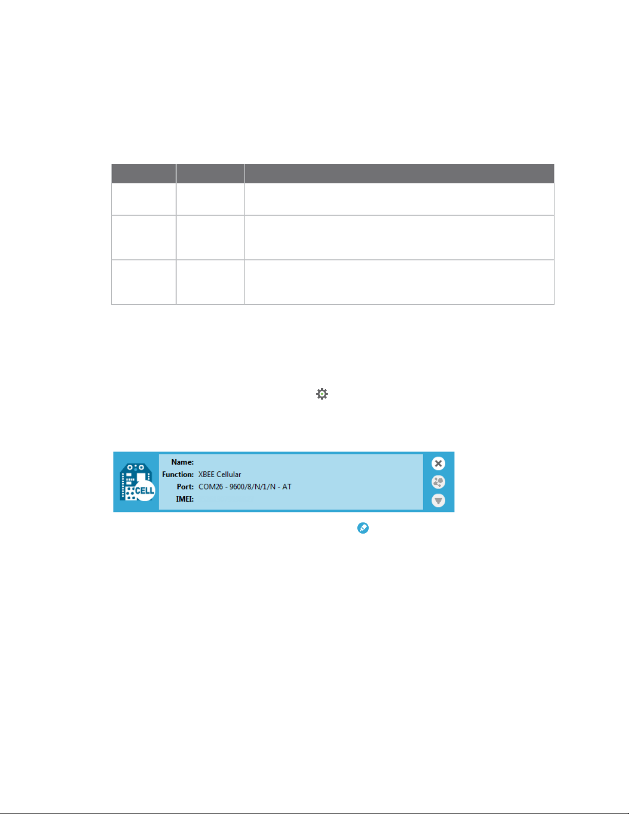
Note If you do not know the port number, open XCTU and look at the XBee Smart Modem in the Radio
Modules list. This view provides the port number and baud rate, as in the figure below where the baud
rate is 9600 b/s.
7. Type the baud rate and press Enter. You must match the device's current baud rate.
XCTUprovides the current baud rate in the BD Baud Rate field. In this example you would type
9600.
8. Press Y if you want an auto-generated example. Press Enter to build your own CoAP request.
9. If you press Y it generates a message with:
n Method: POST
n URI: example
n payload:hello world
n token: test
The send and receive message must match the same token and message id. Otherwise, the client reattempts the connection by sending out the request.
In the following figure, the payload contains the server response to the query. It shows the results for
when you press Enter rather than Y.
Digi XBee3 Cellular LTE-M Global Smart Modem User Guide
42
Page 43

Getting started with the XBee Smart Modem Development Kit Get started with CoAP
Digi XBee3 Cellular LTE-M Global Smart Modem User Guide
43
Page 44

Getting started with the XBee Smart Modem
Development Kit
Configure the XBee Smart Modem using Digi Remote
Manager
Configure the XBee Smart Modem using Digi Remote Manager
Use Digi Remote Manager (https://remotemanager.digi.com/) to perform the operations in this
section. Each operation requires that you enable Remote Manager with the DO command and that
you connect the XBee Smart Modem to an access point that has an external Internet connection to
allow access to Digi Remote Manager.
Note Digi is consolidating our cloud services, Digi Device Cloud and Digi Remote Manager®, under the
Remote Manager name. This phased process does not affect device functionality or the functionality
of the web services and other features. However, customers will find that some user interface and
firmware functionality mention both Device Cloud and Digi Remote Manager.
Create a Remote Manager account
Digi Remote Manager is an on-demand service with no infrastructure requirements. Remote devices
and enterprise business applications connect to Remote Manager through standards-based web
services. This section describes how to configure and manage an XBee using Remote Manager. For
detailed information on using Remote Manager, refer to the Remote Manager User Guide, available
via the Documentation tab in Remote Manager.
Before you can manage an XBee with Remote Manager, you must create a Remote Manager account.
To create a Remote Manager account:
1. Go to https://www.digi.com/products/cloud/digi-remote-manager.
2. Click 30 DAY FREETRIAL/LOGIN.
3. Follow the online instructions to complete account registration. You can upgrade your
Developer account to a paid account at any time.
When you are ready to deploy multiple XBee Smart Modems in the field, upgrade your account to
access additional Remote Manager features.
Get the XBee Smart Modem IMEI number
Before adding an XBee to your Remote Manager account inventory, you need to determine the
International Mobile Equipment Identity (IMEI) number for the device. Use XCTUto view the IMEI
number by querying the IM parameter.
Add a XBee Smart Modem to Remote Manager
To add an XBee to your Remote Manager account inventory, follow these steps:
Go to https://remotemanager.digi.com/.
1. Log in to your account
2. Click Device Management > Devices.
3. Click Add Devices. The Add Devices dialog appears.
4. Select IMEI#, and type or paste the IMEI number of the XBee you want to add. The IM
(IMEI)command provides this number.
Digi XBee3 Cellular LTE-M Global Smart Modem User Guide
44
Page 45

Getting started with the XBee Smart Modem Development Kit Software libraries
5. Click Add to add the device. The XBee is added to your inventory.
6. Click OK to close the Add Devices dialog and return to the Devices view.
Update the firmware
XBee Smart Modem supports Remote Manager firmware updates. To perform a firmware update, use
the following steps.
1. Download the updated firmware file for your device from Digi's support site. This is a zip file
containing .ebin and .mxi files for import.
2. Unzip the file.
3. In your Remote Manager account, click Device Management > Devices.
4. Select the first device you want to update.
5. To select multiple devices (must be of the same type), press the Control key and select
additional devices.
6. Click More in the Devices toolbar and select Update Firmware from the Update category of
the More menu. The Update Firmware dialog appears.
7. Click Browse to select the .ebin file that you unzipped earlier.
8. Click Update Firmware. The updated devices automatically reboot when the updates are
complete.
Software libraries
One way to communicate with the XBee device is by using a software library. The libraries available
for use with the XBee Smart Modem include:
n XBee Java library
n XBee Python library
The XBee Java Library is a Java API. The package includes the XBee library, its source code and a
collection of samples that help you develop Java applications to communicate with your XBee devices.
The XBee Python Library is a Python API that dramatically reduces the time to market of XBee
projects developed in Python and facilitates the development of these types of applications, making it
an easy process.
Digi XBee3 Cellular LTE-M Global Smart Modem User Guide
45
Page 46

Get started with MicroPython
This guide provides an overview of how to use MicroPython with the XBee Smart Modem. For in-depth
information and more complex code examples, refer to the Digi MicroPython Programming Guide.
Continue with this guide for simple examples to get started using MicroPython on the XBee Smart
Modem.
About MicroPython 47
MicroPython on the XBee Smart Modem 47
Use XCTU to enter the MicroPython environment 47
Use the MicroPython Terminal in XCTU 48
Example: hello world 48
Example: turn on an LED 48
Example: code a request help button 49
Exit MicroPython mode 54
Other terminal programs 54
Use picocom in Linux 55
Digi XBee3 Cellular LTE-M Global Smart Modem User Guide
46
Page 47

Get started with MicroPython About MicroPython
About MicroPython
MicroPython is an open-source programming language based on Python 3, with much of the same
syntax and functionality, but modified to fit on small devices with limited hardware resources, such as
microcontrollers, or in this case, a cellular modem.
Why use MicroPython
MicroPython enables on-board intelligence for simple sensor or actuator applications using digital and
analog I/O. MicroPython can help manage battery life. Cryptic readings can be transformed into useful
data, excess transmissions can be intelligently filtered out, modern sensors and actuators can be
employed directly, and logic can glue inputs and outputs together in an intelligent way.
For more information about MicroPython, see www.micropython.org.
For more information about Python, see www.python.org.
MicroPython on the XBee Smart Modem
The XBee Smart Modem has MicroPython running on the device itself. You can access a MicroPython
prompt from the XBee Smart Modem when you install it in an appropriate development board (XBDB
or XBIB), and connect it to a computer via a USB cable.
Note MicroPython does not work with SPI.
The examples in this guide assume:
n You have XCTU on your computer. See Configure the device using XCTU.
n You have a terminal program installed on your computer. We recommend using the Use the
MicroPython Terminal in XCTU. This requires XCTU 6.3.7 or higher.
n You have an XBee Smart Modem installed in an appropriate development board such as an
XBIB-U-DEV or an XBIB-2.
Note Most examples in this guide require the XBIB-U-DEV board.
n The XBee Smart Modem is connected to the computer via a USB cable and XCTU recognizes it.
n The board is powered by an appropriate power supply, 12 VDC and at least 1.1 A.
Use XCTU to enter the MicroPython environment
To use the XBee Smart Modem in the MicroPython environment:
1. Use XCTU to add the device(s); see Configure the device using XCTU and Add a device.
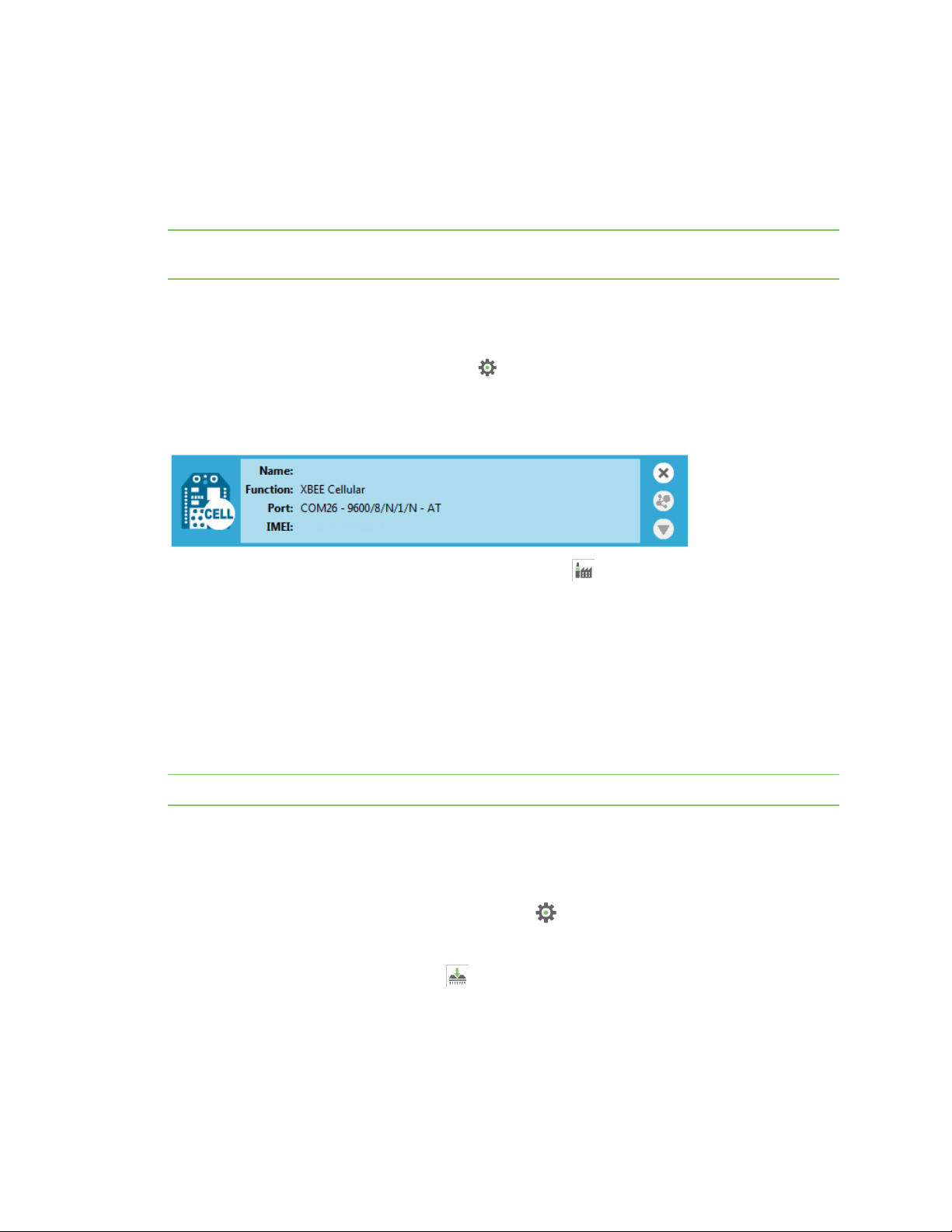
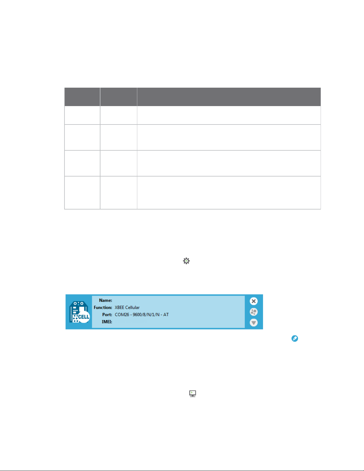
2. The XBee Smart Modem appears as a box in the Radio Modules information panel. Each
module displays identifying information about itself.
3. Click this box to select the device and load its current settings.
4. To set the device's baud rate to 115200 b/s, in the BD field select 115200 [7] and click the
Write button . We recommend using flow control to avoid data loss, especially when pasting
large amounts of code/text.
Digi XBee3 Cellular LTE-M Global Smart Modem User Guide
47
Page 48

Get started with MicroPython Use the MicroPython Terminal in XCTU
5. To put the XBee Smart Modem into MicroPython mode, in the APfield select MicroPython
REPL [4] and click the Write button .
6. Note what COM port(s) the XBee Smart Modem is using, because you will need this information
when you use terminal communication.
Use the MicroPython Terminal in XCTU
You can use the MicroPython Terminal to communicate with the XBee Smart Modem when it is in
MicroPython mode.1This requires XCTU 6.3.7 or higher. To enter MicroPython mode, follow the steps
in Use XCTU to enter the MicroPython environment. To use the MicroPython Terminal:
Click the Tools drop-down menu and select MicroPython Terminal. The terminal opens.
1.
2. Click Open.
3. In the Select the Serial/USB port area, click the COM port that the device uses.
4. Verify that the baud rate and other settings are correct.
Click OK. The Open icon changes to Close , indicating that the device is properly connected.
5.
You can now type or paste MicroPython code in the terminal.
Example: hello world
1. At the MicroPython >>> prompt, type the Python command: print("Hello, World!")
2. Press Enter to execute the command. The terminal echos back Hello, World!.
Example: turn on an LED
1. Note the DS4 LED on the XBIB board. The following image highlights it in a red box. The LED is
normally off.
1
See Other terminal programs if you do not use the MicroPython Terminal in XCTU.
Digi XBee3 Cellular LTE-M Global Smart Modem User Guide
48
Page 49

Get started with MicroPython Example: code a request help button
2. At the MicroPython >>> prompt, type the commands below, pressing Enter after each one.
After entering the last line of code, the LED illuminates. Anything after a # symbol is a
comment, and you do not need to type it.
Note You can easily copy and paste code from the online version of this Guide. Use caution with the
PDF version, as it may not maintain essential indentations.
import machine
from machine import Pin
led = Pin("D4", Pin.OUT, value=0) # Makes a pin object set to output 0.
# One might expect 0 to mean OFF and 1 to mean ON, and this is normally the case.
# But the LED we are turning on and off is setup as what is# known as "active
low".
# This means setting the pin to 0 allows current to flow through the LED and then
through the pin, to ground.
3. To turn it off, type the following and press Enter:
led.value(1)
You have successfully controlled an LED on the board using basic I/O!
Example: code a request help button
This example provides a fast, deep dive into MicroPython designed to let you see some of the powerful
things it can do with minimal code. It is not meant as a tutorial; for in-depth examples refer to the Digi
MicroPython Programming Guide.
Digi XBee3 Cellular LTE-M Global Smart Modem User Guide
49
Page 50

Get started with MicroPython Example: code a request help button
Many stores have help buttons in their aisles that a customer can press to alert the store staff that
assistance is required in that aisle. You can implement this type of system using the Digi XBee Smart
Modem, and this example provides the building blocks for such a system. This example, based on SMS
paging, can have many other uses such as alerting someone with a text to their phone if a water
sensor in a building detects water on the floor, or if a temperature sensor reports a value that is too
hot or cold relative to normal operation.
Enter MicroPython paste mode
In the following examples it is helpful to know that MicroPython supports paste mode, where you can
copy a large block of code from this user guide and paste it instead of typing it character by character.
To use paste mode:
1. Copy the code you want to run. For example, copy the following code that is the code from the
LED example:
from machine import Pin
led = Pin("D4", Pin.OUT, value=0)
Note You can easily copy and paste code from the online version of this Guide. Use caution with the
PDF version, as it may not maintain essential indentations.
2. In the terminal, at the MicroPython >>> prompt type Ctrl-+E to enter paste mode. The terminal
displays paste mode; Ctrl-C to cancel, Ctrl-D to finish.
3. The code appears in the terminal occupying four lines, each line starts with its line number and
three = symbols. For example line 1 starts with 1===.
4. If the code is correct, press Ctrl+D to run the code and you should once again see the DS4 LED
turn on. If you get a Line 1 SyntaxError: invalid syntax error, see Syntax error at line 1.
(If you wish to exit paste mode without running the code, for example, or if the code did not
copy correctly, press Ctrl+C to cancel and return to the normal MicroPython >>> prompt).
5. Next turn the LED off. Copy the code below:
from machine import Pin
led = Pin("D4", Pin.OUT, value=1)
print("DS4 LED now OFF!")
print("Paste Mode Successful!")
6. Press Ctrl+E to enter paste mode.
7. Press Ctrl + Shift + V or right-click in the Terminal and select Paste to paste the copied code.
8. If the code is correct, press Ctrl+D to run it. The LED should turn off and you should see two
confirmation messages print to the screen.
Catch a button press
For this part of the example, you write code that responds to a button press on the XBIB-U-DEV board
that comes with the XBee Smart Modem Development Kit. The code monitors the pin connected to
the button on the board labeled SW2.
Digi XBee3 Cellular LTE-M Global Smart Modem User Guide
50
Page 51

Get started with MicroPython Example: code a request help button
On the board you see DIO0 written below SW2, to the left of the button. This represents the pin that
the button is connected to.
In MicroPython, you will create a pin object for the pin that is connected to the SW2 button. When you
create the pin object, the DIO0 pin is called D0 for short.
The loop continuously checks the value on that pin and once it goes to 0 (meaning the button has been
pressed) a print() call prints the message Button pressed! to the screen.
At the MicroPython >>> prompt, copy the following code and enter it into MicroPython using paste
mode and then run it:
# Import the Pin module from machine, for simpler syntax.
from machine import Pin
# Create a pin object for the pin that the button "SW2" is connected to.
dio0 = Pin("D0", Pin.IN, Pin.PULL_UP)
# Give feedback to inform user a button press is needed.
print("Waiting for SW2 press...")
# Create a WHILE loop that checks for a button press.
while (True):
if (dio0.value() == 0): # Once pressed.
print("Button pressed!") # Print message once pressed.
break # Exit the WHILE loop.
# When you press SW2, you should see "Button pressed!" printed to the screen.
# You have successfully performed an action in response to a button press!
Note You can easily copy and paste code from the online version of this Guide. Use caution with the
PDF version, as it may not maintain essential indentations.
Note If you have problems pasting the code, see Syntax error at line 1.
Digi XBee3 Cellular LTE-M Global Smart Modem User Guide
51
Page 52

Get started with MicroPython Example: code a request help button
Send a text (SMS) when the button is pressed
After creating a while loop that checks for a button press, add sending an SMS to your code. Instead of
printing Button pressed! to the screen, this code sends Button pressed to a cell phone as a text
(SMS) message.
To accomplish this, use the sms_send() method, which sends a string to a given phone number. It
takes the arguments in the order of
1. <phone number>
2. <message-to-be-sent>
Before you run this part of the example, you must create a variable that holds the phone number of
the cell phone or mobile device you want to receive the SMS.
1. To do this, at the MicroPython >>> prompt, type the following command, replacing 1123456789
with the full phone number (no dashes, spaces, or other symbols) and press Enter:
ph = 1123456789
2. After you create this ph variable with your phone number, copy the code below and enter it
into MicroPython using paste mode and then run it.
from machine import Pin
import network # Import network module
import time
c = network.Cellular() # initialize cellular network parameter
dio0 = Pin("D0", Pin.IN, Pin.PULL_UP)
while not c.isconnected(): # While no network connection.
print("Waiting for connection to cell network...")
time.sleep(5)
print("Connected.")
# Give feedback to inform user a button press is needed.
print("Waiting for SW2 press...")
while (True):
if (dio0.value() == 0):
# When SW2 is pressed, the module will send an SMS
# message saying "Button pressed" to the given target cell phone number.
try:
c.sms_send(ph, 'Button Pressed')
print("Sent SMS successfully.")
except OSError:
print("ERROR- failed to send SMS.")
# Exit the WHILE loop.
break
Note You can easily copy and paste code from the online version of this Guide. Use caution with the
PDF version, as it may not maintain essential indentations.
Note If you have problems pasting the code, see Syntax error at line 1. For SMS failures, see Error
Failed to send SMS.
Digi XBee3 Cellular LTE-M Global Smart Modem User Guide
52
Page 53

Get started with MicroPython Example: code a request help button
Add the time the button was pressed
After you add the ability to send an SMS to the code, add functionality to insert the time at which the
button was pressed into the SMS that is sent. To accomplish this:
1. Create a UDP socket with the socket() method.
2. Save the IP address and port of the time server in the addr variable.
3. Connect to the time server with the connect() method.
4. Send hello to the server to prompt it to respond with the current date and time.
5. Receive and store the date/time response in the buf variable.
6. Send an SMSin the same manner as before using the sms_send() method, except that you add
the time into the SMS message, such that the message reads: [Button pressed at: YYYY-MM-
DD HH:MM:SS]
To verify that your phone number is still in the memory, at the MicroPython >>> prompt, type ph and
press Enter.
If MicroPython responds with your number, copy the following code and enter it into MicroPython
using paste mode and then run it. If it returns an error, enter your number again as shown in Send a
text (SMS) when the button is pressed. With your phone number in memory in the ph variable, copy
the code below and enter it into MicroPython using paste mode and then run it.
from machine import Pin
import network
import usocket
import time
c = network.Cellular()
dio0 = Pin("D0", Pin.IN, Pin.PULL_UP)
while not c.isconnected(): # While no network connection.
print("Waiting for connection to cell network...")
time.sleep(5)
print("Connected.")
# Give feedback to inform user a button press is needed.
print("Waiting for SW2 press...")
while (1):
if (dio0.value() == 0):
# When button pressed, now the module will send "Button Press" AND
# the time at which it was pressed in an SMS message to the given
# target cell phone number.
socketObject = usocket.socket(usocket.AF_INET, usocket.SOCK_DGRAM)
# Connect the socket object to the web server specified in "address".
addr = ("52.43.121.77", 10002)
socketObject.connect(addr)
bytessent = socketObject.send("hello")
print("Sent %d bytes on socket" % bytessent)
buf = socketObject.recv(1024)
# Send message to the given number. Handle error if it occurs.
try:
c.sms_send(ph, 'Button Pressed at: ' + str(buf))
print("Sent SMS successfully.")
except OSError:
print("ERROR- failed to send SMS.")
# Exit the WHILE loop.
break
Digi XBee3 Cellular LTE-M Global Smart Modem User Guide
53
Page 54

Get started with MicroPython Exit MicroPython mode
Note You can easily copy and paste code from the online version of this Guide. Use caution with the
PDF version, as it may not maintain essential indentations.
Now you have a system based on the XBee Smart Modem that sends an SMS in response to a certain
input, in this case a simple button press.
Note If you have problems pasting the code, see Syntax error at line 1. For SMS failures, see Error
Failed to send SMS.
Exit MicroPython mode
To exit MicroPython mode:
In the XCTU MicroPython Terminal, click the green Close button .
1.
2. Click Close at the bottom of the terminal to exit the terminal.
In XCTU's Configuration working mode , change AP API Enable to another mode and click
3.
the Write button . We recommend changing to Transparent mode [0], as most of the
examples use this mode.
Other terminal programs
If you do not use the MicroPython Terminal in XCTU, you can use other terminal programs to
communicate with the XBee Smart Modem. If you use Microsoft Windows, follow the instructions for
Tera Term, if you use Linux, follow the instructions for picocom. To download these programs:
n Tera Term for Windows; see https://ttssh2.osdn.jp/index.html.en.
n Picocom for Linux; see https://developer.ridgerun.com/wiki/index.php/Setting_up_Picocom_-_
Ubuntu and for the source code and in-depth information https://github.com/npat-
efault/picocom.
Tera Term for Windows
With the XBee Smart Modem in MicroPython mode (AP = 4), you can access the MicroPython prompt
using a terminal.
1. Open Tera Term. The Tera Term: New connection window appears.
2. Click the Serial radio button to select a serial connection.
3. From the Port: drop-down menu, select the COM port that the XBee Smart Modem is
connected to.
4. Click OK. The COMxx - Tera Term VT terminal window appears and Tera Term attempts to
connect to the device at a baud rate of 9600 b/s. The terminal will not allow communication
with the device since the baud rate setting is incorrect. You must change this rate as it was
previously set to 115200 b/s.
5. Click Setup and Serial Port. The Tera Term: Serial port setup window appears.
Digi XBee3 Cellular LTE-M Global Smart Modem User Guide
54
Page 55

Get started with MicroPython Use picocom in Linux
6. In the Tera Term: Serial port setup window, set the parameters to the following values:
n Port: Shows the port that the XBee Smart Modem is connected on.
n Baud rate:115200
n Data: 8 bit
n Parity: none
n Stop: 1 bit
n Flow control: hardware
n Transmit delay: N/A
7. Click OK to apply the changes to the serial port settings. The settings should go into effect
right away.
8. To verify that local echo is not enabled and that extra line-feeds are not enabled:
a. In Tera Term, click Setup and select Terminal.
b. In the New-line area of the Tera Term: Serial port setup window, click the
Receive drop-down menu and select CR if it does not already show that value.
c. Make sure the Local echo box is not checked.
9. Click OK.
10. Press Ctrl+B to get the MicroPython version banner and prompt.
Now you can type MicroPython commands at the >>> prompt.
Use picocom in Linux
With the XBee Smart Modem in MicroPython mode (AP = 4), you can access the MicroPython prompt
using a terminal.
Note The user must have read and write permission for the serial port the XBee Smart Modem is
connected to in order to communicate with the device.
Digi XBee3 Cellular LTE-M Global Smart Modem User Guide
55
Page 56

Get started with MicroPython Use picocom in Linux
1. Open a terminal in Linux and type picocom -b 115200 /dev/ttyUSB0. This assumes you have
no other USB-to-serial devices attached to the system.
2. Press Ctrl+B to get the MicroPython version banner and prompt. You can also press Enter to
bring up the prompt.
If you do have other USB-to-serial devices attached:
1. Before attaching the XBee Smart Modem, check the directory /dev/ for any devices named
ttyUSBx, where x is a number. An easy way to list these is to type: ls /dev/ttyUSB*. This
produces a list of any device with a name that starts with ttyUSB.
2. Take note of the devices present with that name, and then connect the XBee Smart Modem.
3. Check the directory again and you should see one additional device, which is the XBee Smart
Modem.
4. In this case, replace /dev/ttyUSB0 at the top with /dev/ttyUSB<number>, where <number>
is the new number that appeared.
5. It should connect and show Terminal ready.
Now you can type MicroPython commands at the >>> prompt.
Digi XBee3 Cellular LTE-M Global Smart Modem User Guide
56
Page 57

Technical specifications
Interface and hardware specifications 58
Cellular RF characteristics 58
Bluetooth RF characteristics 58
Cellular Networking specifications 58
Power requirements 59
Power consumption 59
Electrical specifications 59
Regulatory approvals 60
Digi XBee3 Cellular LTE-M Global Smart Modem User Guide
57
Page 58

Technical specifications Interface and hardware specifications
Interface and hardware specifications
The following table provides the interface and hardware specifications for the device.
Specification Value
Dimensions 24.38 mm x 32.94 mm (0.960 x 1.297 in)
Weight 5 g (0.18 oz)
Operating temperature
Antenna connector
Digital I/O 13 I/O lines
ADC 4 10-bit analog inputs
Cellular chipset u-blox SARA-R410M
Form factor Digi XBee 20-pin through-hole
SIM size 4FF Nano
Cellular RF characteristics
The following table provides the RF characteristics for the device.
Specification Value
Transmit power Up to 23 dBm, Power Class 3
Receive sensitivity -105 dBm
-40 to +85 °C
Cellular: U.FL
Bluetooth: U.FL
Bluetooth RF characteristics
The following table provides the Bluetooth RF characteristics for the device.
Specification Value
Transmit power Up to 8 dBm
Receive sensitivity, 1 Mb/s data rate -94 dBm
Receive sensitivity, 2 Mb/s data rate -90 dBm
Operating frequency band ISM 2.4 - 2.4835 GHz
Cellular Networking specifications
The following table provides the networking and carrier specifications for the device.
Digi XBee3 Cellular LTE-M Global Smart Modem User Guide
58
Page 59

Technical specifications Power requirements
Specification Value
Carrier and technology AT&T LTE-M
Compatible with other LTE-M carriers, see supported bands
Supported bands LTE Bands 2, 4, 5, 12
Security Digi Trustfence™
Data throughput TBD
Downlink/uplink speeds Up to 375 kb/s
Duplex mode Half-duplex
Power requirements
The following table provides the power requirements for the device.
Specification Value
Supply voltage 3.3 to 4.3 V
Power consumption
Specification State Typical current VCC = 3.3 V
Peak transmit current Bluetooth disabled 550 mA
Average transmit current Active TX/RX @ 23 dBm 235 mA
Active mode current Idle/connected, listening 24 mA
Power save mode current 20 µA
Deep sleep current 10 µA
Electrical specifications
The following table provides the electrical specifications for the XBee Smart Modem.
Symbol Parameter Condition Min Typical Max Units
VCCMAX Maximum
limits of VCC
line
Bluetooth enabled 610 mA
0 4.3 V
Digi XBee3 Cellular LTE-M Global Smart Modem User Guide
59
Page 60

Technical specifications Regulatory approvals
Symbol Parameter Condition Min Typical Max Units
VDD_IO Internal
supply
voltage for
I/O
VI Voltage on
any pin
VIL Input low
voltage
VIH Input high
voltage
VOL Voltage
output low
VOH Voltage
output high
I_IN Input
leakage
current
RPU Internal pull-
up resistor
RPD Internal pull-
down
resistor
(VCC - 0.15 V) or
3.3 V, whichever
is lower
-0.3 VDD_IO +
0.7*VDD_IO V
Sinking 3 mA, VCC =
3.3 V
Sourcing 3 mA, VCC
= 3.3 V
High Z state I/O
connected to Ground
or VDD_IO
Enabled 40 kΩ
Enabled 40 kΩ
0.8*VDD_IO V
VCC or 3.3 V,
whichever is
lower
0.1 30 nA
3.3 V
V
0.3
0.3*VDD_IOV
0.2*VDD_IOV
Regulatory approvals
The following table provides the regulatory and carrier approvals for the device.
Specification Value
United States
Industry Canada
RoHS Lead-free and RoHS compliant
AT&T end-device certified Complete
PTCRB Complete
FCC ID: MCQ-XB3M1
FCC ID: XPY2AGQN4NNN
IC: 1846A-XB3M1
IC: 8595A-2AGQN4NNN
Digi XBee3 Cellular LTE-M Global Smart Modem User Guide
60
Page 61

Hardware
Mechanical drawings 62
Pin signals 62
RSSI PWM 64
SIM card 64
The Associate LED 65
Digi XBee3 Cellular LTE-M Global Smart Modem User Guide
61
Page 62

Hardware Mechanical drawings
Mechanical drawings
The following figures show the mechanical drawings for the XBee Smart Modem. All dimensions are in
inches.
Pin signals
The pin locations are:
Digi XBee3 Cellular LTE-M Global Smart Modem User Guide
62
Page 63

Hardware Pin signals
The following table shows the pin assignments for the through-hole device. In the table, low-asserted
signals have a horizontal line above signal name.
Pin Name Direction Default Description
Pin Name Direction Default Description
V
1
CC
Power supply
2 DOUT Output Output UART Data Out
DIN / CONFIG
3
Input Input UART Data In
4 DIO12 / SPI_MISO Either Disabled Digital I/O 12 or SPI Slave
Output line
5 RESET Input
6 PWM0 / RSSI / DIO10/USB_VBUS Either Output PWM Output 0 / RX Signal
Strength Indicator / Digital
I/O 10 or USB VBUS line
1
7 DIO11/USB D+ Either Disabled Digital I/O 11 or USB D+ line
8 USB D- Direct USB D- line
DTR / SLEEP_RQ/ DIO8
9
Either Disabled Pin Sleep Control Line or
Digital I/O 8
10 GND Ground
11 DIO4 / SPI_MOSI Either Disabled Digital I/O 4 or SPI Slave
Input Line
CTS / DIO7
12
Either Output Output Clear-to-Send Flow
Control or Digital I/O 7
ON /SLEEP/DIO9
13
Output Output Module Status Indicator or
Digital I/O 9
14 VREF - Feature not supported on
this device. Used on other
XBee devices for analog
voltage reference.
15 Associate / DIO5 Either Output Associated Indicator, Digital
I/O 5
RTS / DIO6
16
Either Disabled Input Request-to-Send Flow
Control, Digital I/O 6
AD3/DIO3/SPI_SS
17
Either Disabled Analog Input 3 or Digital I/O
3, SPI low enabled select
line
1
The XBee3 device is 5 V tolerant on this pin whereas most other XBee devices are not.
Digi XBee3 Cellular LTE-M Global Smart Modem User Guide
63
Page 64

Hardware RSSI PWM
Pin Name Direction Default Description
18 AD2 / DIO2 / SPI_CLK Either Disabled Analog Input 2 or Digital I/O
2, SPI Clock line
19
20 AD0/DIO0 Either Input Analog Input 0, Digital I/O 0
Pin connection recommendations
The recommended minimum pin connections are VCC, GND, DIN, DOUT, RTS, DTR and RESET.
Firmware updates require access to these pins.
RSSI PWM
The XBee Smart Modem features an RSSI/PWM pin (pin 6) that, if enabled, adjusts the PWM output to
indicate the signal strength of the cellular connection. Use P0 (DIO10/PWM0 Configuration) to enable
the RSSI pulse width modulation (PWM) output on the pin. If P0 is set to 1, the RSSI/PWM pin outputs a
PWM signal where the frequency is adjusted based on the received signal strength of the cellular
connection.
The RSSI/PWM output is enabled continuously unlike other XBee products where the output is enabled
for a short period of time after each received transmission. If running on the XBIB development board,
DIO10 is connected to the RSSI LEDs, which may be interpreted as follows:
PWM duty cycle
AD1/DIO1/ SPI_ATTN
Number of LEDs turned
on Received signal strength (dBm)
Either Disabled
Analog Input 1 or Digital I/O
1, SPI Attention line output
79.39% or more 3 -83 dBm or higher
62.42% to
79.39%
45.45% to
62.42%
Less than
45.45%
SIM card
The XBee Smart Modem uses a 4FF (Nano) size SIM card.
2 -93 to -83 dBm
1 -103 to -93 dBm
0
CAUTION! Never insert or remove SIM card while the power is on!
Less than -103 dBm, or no cellular network
connection
Digi XBee3 Cellular LTE-M Global Smart Modem User Guide
64
Page 65

Hardware The Associate LED
The Associate LED
The following table describes the Associate LED functionality. For the location of the Associate LED on
the XBIB-U development board, see number 6 on the XBIB-U-DEV reference.
Blink
LED status
On, solid Not joined to a mobile network.
timing Meaning
Double blink
Standardsingleblink
The normal association LED signal alternates evenly between high and low as shown below:
Where the low signal means LED off and the high signal means LED on.
When CI is not 0 or 0xFF, the Associate LED has a different blink pattern that looks like this:
½second
1second
The last TCP/UDP attempt failed. If the LED has this pattern, you
may need to check DI (Device Cloud Indicator) or CI
(Protocol/Connection Indication) for the cause of the error.
Normal operation.
Digi XBee3 Cellular LTE-M Global Smart Modem User Guide
65
Page 66

Antenna recommendations
Antenna placement 67
Digi XBee3 Cellular LTE-M Global Smart Modem User Guide
66
Page 67

Antenna recommendations Antenna placement
Antenna placement
For optimal cellular reception, keep the antenna as far away from metal objects and other electronics
(including the XBee Smart Modem) as possible. Often, small antennas are desirable, but come at the
cost of reduced range and efficiency.
Digi XBee3 Cellular LTE-M Global Smart Modem User Guide
67
Page 68

Design recommendations
Power supply considerations 69
Minimum connection diagram 69
Heat considerations and testing 69
Heat sink guidelines 71
Add a fan to provide active cooling 72
Digi XBee3 Cellular LTE-M Global Smart Modem User Guide
68
Page 69

Design recommendations Power supply considerations
Power supply considerations
When considering a power supply, use the following design practices.
1. Power supply ripple should be less than 75 mV peak to peak.
2. The power supply should be capable of providing a minimum of 750 mAat 3.3 V (2.5 W).
3. Place sufficient bulk capacitance on the XBee VCC pin to maintain voltage above the minimum
specification during transmissions. Power consumption lists the peak current during
transmitting.
4. Place smaller high frequency ceramic capacitors very close to the XBee Smart Modem VCC pin
to decrease high frequency noise.
5. Use a wide power supply trace or power plane to ensure it can handle the peak current
requirements with minimal voltage drop. We recommend that the power supply and trace be
designed such that the voltage at the XBee VCC pin does not vary by more than 0.1 V between
light load (~0.5 W) and heavy load (~3 W). The supply should be inside the supply voltage
operating range at startup and should not be allowed to droop lower than 3.2 V during
operation.
Minimum connection diagram
In high EMI noise environments, we recommend adding a 10 nF ceramic capacitor very close to pin 5.
Heat considerations and testing
The XBee Smart Modem may generate significant heat during sustained operation. In addition to
heavy data transfer, other factors that can contribute to heating include ambient temperature, air
flow around the device, and proximity to the nearest cellular tower (the XBee Smart Modem must
transmit at a higher power level when communicating over long distances). Overheating can cause
device malfunction and potential damage. In order to avoid this it is important to consider the
application the XBee Smart Modem is going into and mitigate heat issues if necessary.
We recommend that you perform thermal testing in your application to determine the resulting
steady state temperature of the XBee Smart Modem. Use TP (Temperature) to estimate the device
Digi XBee3 Cellular LTE-M Global Smart Modem User Guide
69
Page 70

Design recommendations Heat considerations and testing
temperature1. Convert the TP reading from hex format to decimal. We recommend that you confirm
the TP readings by attaching a thermocouple directly to the onboard microcontroller (if using a heat
sink place the thermocouple under the thermal gasket), and reading the temperature from the
thermocouple. The location of the microcontroller is shown below.
You also need to know the ambient temperature and the average current consumption during your
test. If you do not have a way to measure current consumption you can estimate it from the table in
the next section.
Use those results to approximate the maximum safe ambient temperature for the XBee Smart
Modem, T
MAX,amb
, with the following equation:
Where:
T
is the steady state temperature of the XBee Smart Modem that you measured during your test
XBee
(if using the TP command, be sure to convert from hex format to decimal).
T
amb,test
I
AVG,test
I
MAX
1
The TP reading may not be calibrated. To compensate for this you can determine an offset to use in the
equations above as follows: With the XBee Smart Modem not powered, allow it to sit at room temperature for
15 - 20 minutes. Power the device and immediately read the TP command. Convert the TP reading from hex
format to decimal and subtract the result from the actual room temperature. Add this offset to to T
numbers above.
is the ambient air temperature during your test.
is the average current measured during your test.
is the maximum current draw expected for your application during transmission.
XBee
in your
Digi XBee3 Cellular LTE-M Global Smart Modem User Guide
70
Page 71

Design recommendations Heat sink guidelines
Heat sink guidelines
Based on the results of your thermal testing you may find it is advisable or required to implement a
method of dissipating excess heat. This section explains how to employ a heat sink on top of the XBee
Smart Modem.
Bolt-down style
A bolt-down style heat sink on top of the XBee Smart Modem provides the best performance. An
example part number is Advanced Thermal Solutions ATS-PCBT1084/ATS-PCB1084. You must use an
electrically non-conductive thermal gasket on top of the XBee device under the area that will be
covered by the heat sink. A thermal gasket such as Gap Pad® 2500S20 is suitable for this purpose. We
recommend using a gasket with thickness of 0.080 in to ensure that components on top of the XBee
device do not tear through the material when pressure is applied to the heat sink.
Install the SIM card prior to placement of the heat sink. Position the thermal gasket and heat sink
assembly on the top of the device so that it covers the microcontroller and surrounding components.
You may cover the section shown inside the red box below; do not cover the U.FL connectors. When
attaching to the host PCB, tighten the mounting hardware until the thermal gasket is compressed
about 25%. Avoid overtightening. To prevent shorting, check that the surface of the heat sink does not
directly contact the XBee device.
Adhesive style heat sink
For applications where the size or mounting requirement of the bolt-down heat sink is undesirable,
you may alternatively employ an adhesive style heat sink. The heat sink should be no more than 8x8
mm in size (one option is the Assman WSW Components V2016B). Use a thermally conductive epoxy to
Digi XBee3 Cellular LTE-M Global Smart Modem User Guide
71
Page 72

Design recommendations Add a fan to provide active cooling
attach the heat sink directly to the microcontroller package, and to prevent shorting ensure that the
heat sink does not touch any other components.
The following table provides a list of typical scenarios and the maximum ambient temperature at
which the XBee Smart Modem can be safely operated under that condition. These are provided only as
guidelines as your results will vary based on application. We recommend that you perform sufficient
testing, as explained in Heat considerations and testing, to ensure that the XBee Smart Modem does
not exceed temperature specifications.
Maximum ambient temperature
Bolt-
Scenario
Average
current
consumption
(VCC = 3.3 V)
Example
application
Peak data
consumed
(MB/hr)
No
heat
sink
Adhesive
heat
sink
Boltdown
heat
sink
down
heat
sink
and fan
Sustained
operation
Device awake,
limited
transmissions
Device primarily
asleep, very
limited
transmissions
235 mA TBD TBD TBD TBD TBD TBD
TBD Updating
traffic sign
TBD Small data
transmission/
receptions
which occur
once per hour
Add a fan to provide active cooling
Another option for heat mitigation is to add a fan to your system to provide active cooling. You can use
a fan instead of or in addition to a heat sink. The XBee Smart Modem offers a fan control feature on
I/O pin DIO11 (pin 7). When the functionality is enabled, that line is pulled high to indicate when the fan
should be turned on. The line is pulled high when the device gets above 70 °C and the cellular
component is running, and turns off when the device drops below 65 °C.
To enable the functionality set P1 (DIO11/PWM1 Configuration) to 1. Note that the I/O pin is not
capable of driving a fan directly; you must implement a circuit to power the fan from a suitable power
source.
1 to 10 TBD TBD TBD 85 °C
Less than
0.1
85°C85 °C
85 °C
85 °C
Digi XBee3 Cellular LTE-M Global Smart Modem User Guide
72
Page 73

Cellular connection process
Connecting 74
Cellular network 74
Data network connection 74
Data communication with remote servers (TCP/UDP) 74
Disconnecting 74
Digi XBee3 Cellular LTE-M Global Smart Modem User Guide
73
Page 74

Cellular connection process Connecting
Connecting
In normal operations, the XBee Smart Modem automatically attempts both a cellular network
connection and a data network connection on power-up. The sequence of these connections is as
follows:
Cellular network
1. The device powers on.
2. It looks for cellular towers.
3. It chooses a candidate tower with the strongest signal.
4. It negotiates a connection.
5. It completes cellular registration.
Data network connection
1. The network enables the evolved packet system (EPS) bearer with an access point name
(APN). See AN (Access Point Name) if you have APNissues.
2. The device negotiates a data connection with the access point.
3. The device receives its IP configuration and address.
4. The AI (Association Indication) command now returns a 0 and the sockets become available.
Data communication with remote servers (TCP/UDP)
Once the data network connection is established, communication with remote servers can be
initiated in several ways:
n Transparent mode data sent to the serial port (see TD (Text Delimiter) and RO (Packetization
Timeout) for timing).
n API mode: Transmit (TX) Request: IPv4 - 0x20 received over the serial connection.
n Digi Remote Manager connectivity begins.
Data communication begins when:
1. A socket opens to the remote server.
2. Data is sent.
Data connectivity ends when:
1. The server closes the connection.
2. The TM timeout expires (see TM (IP Client Connection Timeout)).
3. The cellular network may also close the connection after a timeout set by the network
operator.
Disconnecting
When the XBee Smart Modem is put into Airplane mode or deep sleep is requested:
Digi XBee3 Cellular LTE-M Global Smart Modem User Guide
74
Page 75

Cellular connection process Disconnecting
1. Sockets are closed, cleanly if possible.
2. The cellular connection is shut down.
3. The cellular component is powered off.
Note We recommend entering Airplane mode before resetting or rebooting the device to allow the
cellular module to detach from the network.
Digi XBee3 Cellular LTE-M Global Smart Modem User Guide
75
Page 76

Modes
Select an operating mode 77
Transparent operating mode 78
API operating mode 78
Bypass operating mode 78
USB direct mode 79
Command mode 80
Digi XBee3 Cellular LTE-M Global Smart Modem User Guide
76
Page 77

Modes Select an operating mode
Select an operating mode
The XBee Smart Modem interfaces to a host device such as a microcontroller or computer through a
logic-level asynchronous serial port. It uses a UART for serial communication with those devices.
The XBee Smart Modem supports three operating modes: Transparent operating mode, APIoperating
mode, and Bypass operating mode. The default mode is Transparent operating mode. Use the AP (API
Enable) command to select a different operating mode.
The following flowchart illustrates how the modes relate to each other.
Digi XBee3 Cellular LTE-M Global Smart Modem User Guide
77
Page 78

Modes Transparent operating mode
Transparent operating mode
Devices operate in this mode by default. The device acts as a serial line replacement when it is in
Transparent operating mode. The device queues all serial data it receives through the DIN pin for RF
transmission. When a device receives RF data, it sends the data out through the DOUT pin. You can set
the configuration parameters using Command mode.
The IP (IP Protocol) command setting controls how Transparent operating mode works for the XBee
Smart Modem.
Note Transparent operation is not available when using SPI.
API operating mode
API operating mode is an alternative to Transparent operating mode. API mode is a frame-based
protocol that allows you to direct data on a packet basis. The device communicates UART or SPI data
in packets, also known as API frames. This mode allows for structured communications with
computers and microcontrollers.
The advantages of APIoperating mode include:
n It is easier to send information to multiple destinations
n The host receives the source address for each received data frame
n You can change parameters without entering Command mode
Bypass operating mode
CAUTION! Bypass operating mode is an alternative to Transparent and API modes for
advanced users with special configuration needs. Changes made in this mode might
change or disable the device and we do not recommended it for most users.
In Bypass mode, the device acts as a serial line replacement to the cellular component. In this mode,
the XBee Smart Modem exposes all control of the cellular component's AT port through the UART. If
you use this mode, you must setup the cellular modem directly to establish connectivity. The modem
does not automatically connect to the network.
Note The cellular component can become unresponsive in Bypass mode. See Unresponsive cellular
component in Bypass mode for help in this situation.
When Bypass mode is active, most of the XBee Smart Modem's AT commands do not work. For
example, IM (IMEI)may never return a value, and DB does not update. In this configuration, the
firmware does not test communication with the cellular component (which it does by sending AT
commands). This is useful in case you have reconfigured the cellular component in a way that makes it
incompatible with the firmware. Bypass operating mode exists for users who wish to communicate
directly with the cellular component settings and do not intend to use XBee Smart Modem software
features such as API mode.
Command mode is available while in Bypass mode; see Enter Command mode for instructions.
Enter Bypass operating mode
To configure a device for Bypass operating mode:
Digi XBee3 Cellular LTE-M Global Smart Modem User Guide
78
Page 79

Modes USB direct mode
1. Set the AP (API Enable) parameter value to 5.
2. Send WR (Write) to write the changes.
3. Send FR (Force Reset) to reboot the device.
4. After rebooting, enter Command mode and verify that Bypass operating mode is active by
querying AI (Association Indication) and confirming that it returns a value of 0x2F.
It may take a moment for Bypass operating mode to become active.
Leave Bypass operating mode
To configure a device to leave Bypass operating mode:
1. Set AP (API Enable) to something other than 5.
2. Send WR (Write) to write the changes.
3. Send FR (Force Reset) to reboot the device.
4. After rebooting, enter Command mode and verify that Bypass operating mode is not active by
querying AI (Association Indication) and confirming that it returns a value other than 0x2F.
Restore cellular settings to default in Bypass operating mode
Send AT&F1 to reset the cellular component to its factory profile.
USB direct mode
This mode allows you to access the XBee Smart Modem's USB interface directly through XBee pins 7
and 8. VBUS functionality is optionally provided on XBee pin 6 if you wish to enable and disable USB
mode based on an external source. While in USB mode the cellular modem is not able to communicate
serially with the XBee MCU. All communication with the cellular modem must be performed by the
user via the USB port.
Configure the data pins
Set P1 (DIO11/PWM1 Configuration) to 7 to configure pins 7 and 8 for USB direct mode.
Enable USB direct mode
If you want to externally control the VBUS pin, set P0 (DIO10/PWM0 Configuration) to 6.
Apply a logic high signal to DIO10/PWM0 (pin 6) to enable USB or a logic low signal to disable USB.
Note Although that pin is 5 V tolerant on this device, it operates with the same 3.3 V logic as the other
XBee device pins. For compatibility with other XBee devices we recommend driving the line with no
more than 3.3 V. Moreover, driving the pin at 5 V will cause input leakage current to increase to 3.3 µA
typical.
If you want to enable USB via software, set DO (Device Options) bit 2. Keep in mind that if PO is set to
6, it overrides the behavior of DO bit 2.
You must reset the device to enable or disable USB direct mode.
While in USB direct mode, AI (Association Indication) returns 0x2B.
Digi XBee3 Cellular LTE-M Global Smart Modem User Guide
79
Page 80

Modes Command mode
Enable the VBUS option
The VBUS option only applies when the USB direct mode is enabled.
1. Set P0 (DIO10/PWM0 Configuration) to 6 to enable USB VBUS. When P0 is set to 6 the input
signal to DIO10/PWM0 (pin 6) propagates to the VBUS line of the the cellular component.
2. You can also set DO (Device Options) bit 2 to manually control the VBUS signal. When DObit 2 is
set, the VBUS signal propagated to the VBUS line of the cellular component is on; when bit 2 is
not set the VBUS signal is off.
When PO is set to 6, it overrides the behavior of DO bit 2.
Command mode
Command mode is a state in which the firmware interprets incoming characters as commands. It
allows you to modify the device’s configuration using parameters you can set using AT commands.
When you want to read or set any parameter of the device when operating in Transparent mode, you
have to enter Command mode and send an AT command. Every AT command starts with the letters
AT followed by the two characters that identify the command and then by some optional configuration
values.
The three operating modes are controlled by the AP (API Enable) setting, but Command mode is
always available as a mode the XBee Smart Modem can enter while configured for any of the
operating modes.
Command mode is available on the UART interface in both Transparent and API modes. You cannot
use the SPI interface to enter Command mode.
Enter Command mode
To get a device to switch into this mode, you must issue the following sequence: +++ within one
second. There must be at least one second preceding and following the +++ sequence. Both the
command character (CC) and the silence before and after the sequence (GT) are configurable. When
the device sees a full second of silence in the data stream (the guard time, GT) followed by the string
+++ (without Enter or Return) and another full second of silence, it knows to stop sending data and
start accepting commands locally.
Note Do not press Return or Enter after typing +++ because it will interrupt the guard time silence
and prevent you from entering Command mode.
When the device is in Command mode, it listens for user input and is able to receive AT commands on
the UART. If CT time (default is 10 seconds) passes without any user input, the device drops out of
Command mode and returns to the previous operating mode (Transparent, Bypass, API, Python, and
so forth).
You can customize the command character, the guard times and the timeout in the device’s
configuration settings. For more information, see CC (Command Sequence Character), CT (Command
Mode Timeout) and GT (Guard Times).
Troubleshooting
Failure to enter Command mode is often due to baud rate mismatch. Ensure that the baud rate of the
connection matches the baud rate of the device. By default, the BD parameter = 3 (9600 b/s).
There are two alternative ways to enter Command mode:
Digi XBee3 Cellular LTE-M Global Smart Modem User Guide
80
Page 81

Modes Command mode
n A serial break for six seconds enters Command mode. The "break" command can be issued
from a serial console, and is often a button or menu item.
n Asserting DIN (serial break) upon power up or reset enters Command mode. XCTU guides you
through a reset and automatically issues the break when needed.
Both of these methods temporarily set the device's baud rate to 9600 and return an OK on the UART
to indicate that Command mode is active. When Command mode exits, the device returns to normal
operation at the baud rate the BD parameter is set to.
Send AT commands
Once the device enters Command mode, use the syntax in the following figure to send AT commands.
Every AT command starts with the letters AT, which stands for "attention." The AT is followed by two
characters that indicate which command is being issued, then by some optional configuration values.
To read a parameter value stored in the device’s register, omit the parameter field.
The preceding example changes the IP protocol to SMS.
Multiple AT commands
You can send multiple AT commands at a time when they are separated by a comma in Command
mode; for example, ATSH,SL.
Parameter format
Refer to the list of AT commands for the format of individual AT command parameters. Valid formats
for hexidecimal values include with or without a leading 0x for example FFFF or 0xFFFF.
Response to AT commands
When reading parameters, the device returns the current parameter value instead of an OK message.
Apply command changes
Any changes you make to the configuration command registers using AT commands do not take effect
until you apply the changes. For example, if you send the BD command to change the baud rate, the
actual baud rate does not change until you apply the changes. To apply changes:
1. Send the AC (Apply Changes) command.
or:
2. Exit Command mode.
Make command changes permanent
Issue a WR command command to save the changes. WR writes parameter values to non-volatile
memory so that parameter modifications persist through subsequent resets.
Digi XBee3 Cellular LTE-M Global Smart Modem User Guide
81
Page 82

Modes Command mode
Exit Command mode
1. Send CN (Exit Command mode) followed by a carriage return.
or:
2. If the device does not receive any valid AT commands within the time specified by CT
(Command Mode Timeout), it returns to the mode that the device was last in.
Digi XBee3 Cellular LTE-M Global Smart Modem User Guide
82
Page 83

Sleep modes
About sleep modes 84
Normal mode 84
Pin sleep mode 84
Cyclic sleep mode 84
Cyclic sleep with pin wake up mode 84
Airplane mode 84
SPI mode and sleep pin functionality 84
The sleep timer 85
MicroPython sleep behavior 85
Digi XBee3 Cellular LTE-M Global Smart Modem User Guide
83
Page 84

Sleep modes About sleep modes
About sleep modes
A number of low-power modes exist to enable devices to operate for extended periods of time on
battery power. Use SM (Sleep Mode) to enable these sleep modes.
Normal mode
Set SM to 0 to enter Normal mode.
Normal mode is the default sleep mode. If a device is in this mode, it does not sleep and is always
awake.
Devices in Normal mode are typically mains powered.
Pin sleep mode
Set SM to 1 to enter pin sleep mode.
Pin sleep allows the device to sleep and wake according to the state of the SLEEP_RQ pin (SLEEP_RQ).
When you assert SLEEP_RQ (high), the device finishes any transmit or receive operations, closes any
active connection, and enters a low-power state.
When you de-assert SLEEP_RQ (low), the device wakes from pin sleep.
Cyclic sleep mode
Set SM to 4 to enter Cyclic sleep mode.
Cyclic sleep allows the device to sleep for a specific time and wake for a short time to poll.
If you use the D7 command to enable hardware flow control, the CTS pin asserts (low) when the
device wakes and can receive serial data, and de-asserts (high) when the device sleeps.
Cyclic sleep with pin wake up mode
Set SM to 5 to enter Cyclic sleep with pin wake up mode.
This mode is a slight variation on Cyclic sleep mode (SM = 4) that allows you to wake a device
prematurely by de-asserting the SLEEP_RQ pin (SLEEP_RQ).
In this mode, you can wake the device after the sleep period expires, or if a high-to-low transition
occurs on the SLEEP_RQ pin.
Airplane mode
While not technically a sleep mode, airplane mode is another way of saving power. When set, the
cellular component of the XBee Smart Modem is fully turned off and no access to the cellular network
is performed or possible. Use AM (Airplane Mode) to configure this mode.
SPI mode and sleep pin functionality
SLEEP_RQ/ DIO8 is configured as a peripheral by default and is used for pin sleep to wake the XBee
Smart Modem and put it to sleep. This applies regardless of if the serial interface is UART or SPI.
However, if SLEEP_RQ is not configured as a peripheral and SPI_SSEL is configured as a peripheral,
then pin sleep is controlled by SPI_SSEL rather than by SLEEP_RQ. Asserting SPI_SSEL by driving it low
Digi XBee3 Cellular LTE-M Global Smart Modem User Guide
84
Page 85

Sleep modes The sleep timer
wakes the XBee Smart Modem, or keeps it awake. De-asserting SPI_SSEL by driving it high puts the
device to sleep.
If neither pin is configured as a peripheral, then the device stays awake, being unable to sleep when
SM (Sleep Mode) is 1.
DIO8/SLEEP_RQ configured as
peripheral (D8 = 1)?
DIO3/SPI_SSEL configured as
peripheral (D3 = 1)?
Pin sleep controlled
by...
Yes Yes DIO8/SLEEP_RQ
Yes No DIO8/SLEEP_RQ
No Yes DIO3/SPI_SSEL
No No Neither (pin sleep
does not work)
Advantage of using SPI_SSEL to control sleep:
n One less physical pin connection is required to implement pin sleep. This makes DIO8/SLEEP_
RQ available for another purpose.
Disadvantages of using SPI_SSEL to control sleep:
n The XBee Smart Modem is put to sleep whenever the SPI master negates SPI_SSEL, even if
that was not the intent.
n The XBee Smart Modem begins entering sleep as soon as the control pin is asserted (brought
high). Immediately de-asserting the control pin (bringing it low) only has the effect of
preventing the microcontroller from entering low-power mode before waking up the device -
all other sleep preparations (such as closing sockets) continue as in typical sleep operation.
This can take several seconds, and this added time in the case of an unintended sleep request
may not be acceptable.
The sleep timer
If the device receives serial or RF data in Cyclic sleep mode and Cyclic sleep with pin wake up modes
(SM = 4 or SM = 5), it starts a sleep timer (time until sleep).
n Use ST (Wake Time) to set the duration of the timer.
n When the sleep timer expires the device returns to sleep.
MicroPython sleep behavior
When the XBee Smart Modem enters deep sleep mode, any MicroPython code currently executing is
suspended until the device comes out of sleep. When the XBee Smart Modem comes out of sleep
mode, MicroPython execution continues where it left off.
Upon entering deep sleep mode, the XBee Smart Modem closes any active UDP connections and turns
off the cellular component. As a result, any sockets that were opened in MicroPython prior to sleep
report as no longer being connected. This behavior appears the same as a typical socket
disconnection event will:
Digi XBee3 Cellular LTE-M Global Smart Modem User Guide
85
Page 86

Sleep modes MicroPython sleep behavior
n socket.send raises OSError: ENOTCONN
n socket.sendto raises OSError: ENOTCONN
n socket.recv returns the empty string, the traditional end-of-file return value
n socket.recvfrom returns an empty message, for example:
(b'', (<address from connect()>, <port from connect()>) )
The underlying UDP socket resources have been released at this point.
Digi XBee3 Cellular LTE-M Global Smart Modem User Guide
86
Page 87

Serial communication
Serial interface 88
Serial data 88
UART data flow 88
Serial buffers 89
CTS flow control 89
RTS flow control 89
Enable UART or SPI ports 89
Digi XBee3 Cellular LTE-M Global Smart Modem User Guide
87
Page 88

Serial communication Serial interface
Serial interface
The XBee Smart Modem interfaces to a host device through a serial port. The device can communicate
through its serial port with:
n Through logic and voltage compatible universal asynchronous receiver/transmitter (UART).
n Through a level translator to any serial device, for example, through an RS-232 or USB
interface board.
n Through a serial peripheral interface (SPI) port.
Serial data
A device sends data to the XBee Smart Modem's UART through pin 3 DIN as an asynchronous serial
signal. When the device is not transmitting data, the signals should idle high.
For serial communication to occur, you must configure the UART of both devices (the microcontroller
and the XBee Smart Modem) with compatible settings for the baud rate, parity, start bits, stop bits,
and data bits.
Each data byte consists of a start bit (low), 8 data bits (least significant bit first) and a stop bit (high).
The following diagram illustrates the serial bit pattern of data passing through the device. The
diagram shows UART data packet 0x1F (decimal number 31) as transmitted through the device.
You can configure the UART baud rate, parity, and stop bits settings on the device with the BD, NB,
and SB commands respectively. For more information, see Serial interfacing commands.
In the rare case that a device has been configured with the UART disabled, you can recover the device
to UART operation by holding DIN low at reset time. DIN forces a default configuration on the UART at
9600 baud and it brings the device up in Command mode on the UART port. You can then send the
appropriate commands to the device to configure it for UART operation. If those parameters are
written, the device comes up with the UART enabled on the next reset.
UART data flow
Devices that have a UART interface connect directly to the pins of the XBee Smart Modem as shown in
the following figure. The figure shows system data flow in a UART-interfaced environment. Lowasserted signals have a horizontal line over the signal name.
Digi XBee3 Cellular LTE-M Global Smart Modem User Guide
88
Page 89

Serial communication Serial buffers
Serial buffers
The XBee Smart Modem maintains internal buffers to collect serial and RF data that it receives. The
serial receive buffer collects incoming serial characters and holds them until the device can process
them. The serial transmit buffer collects the data it receives via the RF link until it transmits that data
out the serial or SPI port.
CTS flow control
We strongly encourage you to use flow control with the XBee Smart Modem to prevent buffer
overruns.
CTS flow control is enabled by default; you can disable it with D7 (DIO7/CTS). When the serial receive
buffer fills with the number of bytes specified by FT (Flow Control Threshold), the device de-asserts
CTS (sets it high) to signal the host device to stop sending serial data. The device re-asserts CTS when
less than FT-32 bytes are in the UART receive buffer.
Note Serial flow control is not possible when using the SPI port.
RTS flow control
If you set D6 (DIO6/RTS) to enable RTS flow control, the device does not send data in the serial
transmit buffer out the DOUT pin as long as RTS is de-asserted (set high). Do not de-assert RTS for
long periods of time or the serial transmit buffer will fill.
Enable UART or SPI ports
To enable the UART port, configure DIN and DOUT (P3 and P4 parameters) as peripherals. To enable
the SPI port, enable SPI_MISO, SPI_MOSI, SPI_SSEL , and SPI_CLK (P5 through P9) as peripherals. If
you enable both ports then output goes to the UART until the first input on SPI.
When both the UART and SPI ports are enabled on power-up, all serial data goes out the UART. As
soon as input occurs on either port, that port is selected as the active port and no input or output is
allowed on the other port until the next device reset.
If you change the configuration so that only one port is configured, then that port is the only one
enabled or used. If the parameters are written with only one port enabled, then the port that is not
enabled is not used even temporarily after the next reset.
Digi XBee3 Cellular LTE-M Global Smart Modem User Guide
89
Page 90

Serial communication Enable UART or SPI ports
If both ports are disabled on reset, the device uses the UART in spite of the wrong configuration so
that at least one serial port is operational.
Digi XBee3 Cellular LTE-M Global Smart Modem User Guide
90
Page 91

SPI operation
SPI communications 92
Full duplex operation 93
Low power operation 94
Select the SPI port 94
Force UART operation 95
Data format 95
Digi XBee3 Cellular LTE-M Global Smart Modem User Guide
91
Page 92

SPI operation SPI communications
SPI communications
The XBee Smart Modem supports SPI communications in slave mode. Slave mode receives the clock
signal and data from the master and returns data to the master. The following table shows the
signals that the SPI port uses on the device.
Signal Function
SPI_MOSI
Inputs serial data from the master
(MasterOut,SlaveIn)
SPI_MISO(Master
Outputs serial data to the master
In,Slave Out)
SPI_SCLK
Clocks data transfers on MOSI and MISO
(SerialClock)
SPI_SSEL
Enables serial communication with the slave
(SlaveSelect)
SPI_ATTN (Attention) Alerts the master that slave has data queued to send. The XBee Smart
Modem asserts this pin as soon as data is available to send to the SPI
master and it remains asserted until the SPI master has clocked out all
available data.
In this mode:
n SPI clock rates up to 6 MHz are possible.
n Data is most significant bit (MSB) first; bit 7 is the first bit of a byte sent over the interface.
n Frame Format mode 0 is used. This means CPOL= 0 (idle clock is low) and CPHA = 0 (data is
sampled on the clock’s leading edge).
n The SPI port only supports API Mode (AP = 1).
The following diagram shows the frame format mode 0 for SPI communications.
SPI mode is chip to chip communication. We do not supply a SPI communication option on the device
development evaluation boards.
Digi XBee3 Cellular LTE-M Global Smart Modem User Guide
92
Page 93

SPI operation Full duplex operation
Full duplex operation
The specification for SPI includes the four signals SPI_MISO, SPI_MOSI, SPI_CLK, and SPI_SSEL. Using
these four signals, the SPI master cannot know when the slave needs to send and the SPI slave
cannot transmit unless enabled by the master. For this reason, the SPI_ATTN signal is available in the
design. This allows the SPI slave to alert the SPI master that it has data to send. In turn, the SPI
master is expected to assert SPI_SSEL and start SPI_CLK, unless these signals are already asserted
and active respectively. This, in turn, allows the XBee Smart Modem SPI slave to send data to the
master.
SPI data is latched by the master and slave using the SPI_CLK signal. When data is being transferred
the MISO and MOSI signals change between each clock. If data is not available then these signals will
not change and will be either 0 or 1. This results in receiving either a repetitive 0 or 0xFF. The means
of determining whether or not received data is valid is by packetizing the data with API packets,
without escaping. Valid data to and from the XBee Smart Modem is delimited by 0x7E, a length, the
payload, and finally a checksum byte. Everything else in both directions should be ignored. The bytes
received between frames will be either 0xff or 0x00. This allows the SPI master to scan for a 0x7E
delimiter between frames.
SPI allows for valid data from the slave to begin before, at the same time, or after valid data begins
from the master. When the master is sending data to the slave and the slave has valid data to send in
the middle of receiving data from the master, it allows a true full duplex operation where data is valid
in both directions for a period of time. During this time, the master and slave must simultaneously
transmit valid data at the clock speed so that no invalid bytes appear within an API frame, causing the
whole frame to be discarded.
An example follows to more fully illustrate the SPI interface during the time valid data is being sent in
both directions. First, the master asserts SPI_SSEL and starts SPI_CLK to send a frame to the slave.
Initially, the slave does not have valid data to send the master. However, while it is still receiving data
from the master, it has its own data to send. Therefore, it asserts SPI_ATTN low. Seeing that SPI_
SSEL is already asserted and that SPI_CLK is active, it immediately begins sending valid data, even
while it is receiving valid data from the master. In this example, the master finishes its valid data
before the slave does. The master will have two indications of valid data: The SPI_ATTN line is
asserted and the API frame length is not yet expired. For both of these reasons, the master should
keep SPI_SSEL asserted and should keep SPI_CLK toggling in order to receive the end of the frame
from the slave, even though these signals were originally turned on by the master to send data.
During the time that the SPI master is sending invalid data to the SPI slave, it is important no 0x7E is
included in that invalid data because that would trigger the SPI slave to start receiving another valid
frame.
The following figure illustrates the SPI interface while valid data is being sent in both directions.
Digi XBee3 Cellular LTE-M Global Smart Modem User Guide
93
Page 94

SPI operation Low power operation
Low power operation
Sleep modes generally work the same on SPI as they do on UART. However, due to the addition of SPI
mode, there is an option of another sleep pin, as described below.
By default, Digi configures DIO8 (SLEEP_REQUEST) as a peripheral and during pin sleep it wakes the
device and puts it to sleep. This applies to both the UART and SPI serial interfaces.
If SLEEP_REQUEST is not configured as a peripheral and SPI_SSEL is configured as a peripheral, then
pin sleep is controlled by SPI_SSEL rather than by SLEEP_REQUEST. Asserting SPI_SSEL (pin 17) by
driving it low either wakes the device or keeps it awake. Negating SPI_SSEL by driving it high puts the
device to sleep.
Using SPI_SSEL to control sleep and to indicate that the SPI master has selected a particular slave
device has the advantage of requiring one less physical pin connection to implement pin sleep on SPI.
It has the disadvantage of putting the device to sleep whenever the SPI master negates SPI_SSEL
(meaning time is lost waiting for the device to wake), even if that was not the intent.
If the user has full control of SPI_SSEL so that it can control pin sleep, whether or not data needs to be
transmitted, then sharing the pin may be a good option in order to make the SLEEP_REQUEST pin
available for another purpose.
If the device is one of multiple slaves on the SPI, then the device sleeps while the SPI master talks to
the other slave, but this is acceptable in most cases.
If you do not configure either pin as a peripheral, then the device stays awake, being unable to sleep in
SM1 mode.
Select the SPI port
To force SPI mode, hold DOUT/DIO13 pin 2 low while resetting the device until SPI_ATTN asserts. This
causes the device to disable the UART and go straight into SPI communication mode. Once
configuration is complete, the device queues a modem status frame to the SPI port, which causes the
SPI_ATTN line to assert. The host can use this to determine that the SPI port is configured properly.
This method forces the configuration to provide full SPI support for the following parameters:
n D1 (This parameter will only be changed if it is at a default of zero when the method is
invoked.)
n D2
n D3
n D4
n P2
As long as the host does not issue a WR command, these configuration values revert to previous
values after a power-on reset. If the host issues a WR command while in SPI mode, these same
parameters are written to flash. After a reset, parameters that were forced and then written to flash
become the mode of operation.
If the UART is disabled and the SPI is enabled in the written configuration, then the device comes up in
SPI mode without forcing it by holding DOUT low. If both the UART and the SPI are enabled at the time
of reset, then output goes to the UART until the host sends the first input. If that first input comes on
the SPI port, then all subsequent output goes to the SPI port and the UART is disabled. If the first
input comes on the UART, then all subsequent output goes to the UART and the SPI is disabled.
Once you select a serial port (UART or SPI), all subsequent output goes to that port, even if you apply a
new configuration. The only way to switch the selected serial port is to reset the device. On surfacemount devices, forcing DOUT low at the time of reset has no effect. To use SPI mode on the SMT
modules, assert the SPI_SSEL (pin 17) low after reset and before any UART data is input.
Digi XBee3 Cellular LTE-M Global Smart Modem User Guide
94
Page 95

SPI operation Force UART operation
When the master asserts the slave select (SPI_SSEL) signal, SPI transmit data is driven to the output
pin SPI_MISO, and SPI data is received from the input pin SPI_MOSI. The SPI_SSEL pin has to be
asserted to enable the transmit serializer to drive data to the output signal SPI_MISO. A rising edge
on SPI_SSEL causes the SPI_MISO line to be tri-stated such that another slave device can drive it, if so
desired.
If the output buffer is empty, the SPI serializer transmits the last valid bit repeatedly, which may be
either high or low. Otherwise, the device formats all output in API mode 1 format, as described in
Operate in API mode. The attached host is expected to ignore all data that is not part of a formatted
API frame.
Force UART operation
If you configure a device with only the SPI enabled and no SPI master is available to access the SPI
slave port, you can recover the device to UART operation by holding DIN / CONFIG low at reset time.
DIN/CONFIG forces a default configuration on the UART at 9600 baud and brings up the device in
Command mode on the UART port. You can then send the appropriate commands to the device to
configure it for UART operation. If you write those parameters, the device comes up with the UART
enabled on the next reset.
Data format
SPI only operates in API mode 1. The XBee Smart Modem does not support Transparent mode or API
mode 2 (which escapes control characters). This means that the AP configuration only applies to the
UART, and the device ignores it while using SPI. The reason for this operation choice is that SPI is full
duplex. If data flows in one direction, it flows in the other. Since it is not always possible to have valid
data flowing in both directions at the same time, the receiver must have a way to parse out the valid
data and to ignore the invalid data.
Officially, the invalid data is undefined for SPI. The only requirement is that the start of frame byte
(0x7E) cannot be included in the invalid data as this would cause the receiver to begin parsing a new
frame. But, in reality the XBee Smart Modem sends 0XFF for invalid characters and the S8 and S6
products may send all ones or all zeros.
Digi XBee3 Cellular LTE-M Global Smart Modem User Guide
95
Page 96

AT commands
Special commands 97
Cellular commands 98
Network commands 100
Addressing commands 102
Serial interfacing commands 105
I/O settings commands 107
I/O sampling commands 115
Sleep commands 116
Command mode options 117
MicroPython commands 117
Firmware version/information commands 119
Execution commands 122
Digi XBee3 Cellular LTE-M Global Smart Modem User Guide
96
Page 97

AT commands Special commands
Special commands
The following commands are special commands.
AC (Apply Changes)
Immediately applies new settings without exiting Command mode.
Applying changes means that the device re-initializes based on changes made to its parameter values.
Once changes are applied, the device immediately operates according to the new parameter values.
This behavior is in contrast to issuing the WR (Write) command. The WR command saves parameter
values to non-volatile memory, but the device still operates according to previously saved values until
the device is rebooted or you issue the CN (Exit AT Command Mode) or AC commands.
Parameter range
N/A
Default
N/A
FR (Force Reset)
Resets the device. The device responds immediately with an OK and performs a reset 100 ms later.
If you issue FR while the device is in Command Mode, the reset effectively exits Command mode.
Note We recommend entering Airplane mode before resetting or rebooting the device to allow the
cellular module to detach from the network.
Parameter range
N/A
Default
N/A
RE command
Restore device parameters to factory defaults.
The RE command does not write restored values to non-volatile (persistent) memory. Issue the WR
(Write) command after issuing the RE command to save restored parameter values to non-volatile
memory.
Parameter range
N/A
Default
N/A
WR command
Writes parameter values to non-volatile memory so that parameter modifications persist through
subsequent resets.
Digi XBee3 Cellular LTE-M Global Smart Modem User Guide
97
Page 98

AT commands Cellular commands
Note Once you issue a WR command, do not send any additional characters to the device until after
you receive the OK response.
Parameter range
N/A
Default
N/A
Cellular commands
The following AT commands are cellular configuration and data commands.
PH (Phone Number)
Reads the SIM card phone number. If PH is blank, the XBee Smart Modem is not registered to the
network.
Parameter range
N/A
Default
Set by the cellular carrier via the SIM card
S# (ICCID)
Reads the Integrated Circuit Card Identifier (ICCID) of the inserted SIM.
Parameter range
N/A
Default
Set by the SIMcard
IM (IMEI)
Reads the device's International Mobile Equipment Identity (IMEI).
Parameter range
N/A
Default
Set in the factory
MN (Operator)
Reads the network operator on which the device is registered.
Parameter range
N/A
Digi XBee3 Cellular LTE-M Global Smart Modem User Guide
98
Page 99

AT commands Cellular commands
Default
N/A
MV (Modem Firmware Version)
Read the firmware version string for cellular component communications. See the related VR
(Firmware Version) command.
Parameter range
N/A
Default
Set in the currently loaded firmware
DB (Cellular Signal Strength)
Reads the absolute value of the current signal strength to the cell tower in dB. If DB is blank, the XBee
Smart Modem has not received a signal strength from the cellular component.
Parameter range
0x71 - 0x33 (-113 dBm to -51 dBm) [read-only]
Default
N/A
AN (Access Point Name)
Specifies the packet data network that the modem uses for Internet connectivity. This information is
provided by your cellular network operator. After you set this value, applying changes with AC (Apply
Changes) or CN (Exit Command mode) triggers a network reset.
See Network connection issues if the XBee Smart Modem is not joining the network.
Parameter range
1 - 100 ASCII characters
Default
-
AM (Airplane Mode)
When set, the cellular component of the XBee Smart Modem is fully turned off and no access to the
cellular network is performed or possible.
Parameter range
0 - 1
0 = Normal operation
1 = Airplane mode
Default
0
Digi XBee3 Cellular LTE-M Global Smart Modem User Guide
99
Page 100

AT commands Network commands
Network commands
The following commands are network commands.
IP (IP Protocol)
Sets or displays the IP protocol used for client and server socket connections in IP socket mode.
Parameter range
0 - 4
Value Description
0x00 UDP
0x01 TCP
0x02 Reserved
0x03 Reserved
0x04 Reserved
Default
0x01
TL (SSL/TLS Protocol Version)
Sets the SSL/TLS protocol version used for the SSL socket. If you change the TL value, it does not
affect any currently open sockets. The value only applies to subsequently opened sockets.
Note Due to known vulnerabilities in prior protocol versions, we strongly recommend that you use the
latest TLS version whenever possible.
Range
Value Description
0x00
0x01
0x02
0x03
Default
0x03
SSL v3
TLS v1.0
TLS v1.1
TLS v1.2
TM (IP Client Connection Timeout)
The IP client connection timeout. If there is no activity for this timeout then the connection is closed. If
TMis 0, the connection is closed immediately after the device sends data.
Digi XBee3 Cellular LTE-M Global Smart Modem User Guide
100
 Loading...