

Page 1

ConnectPort™ X Family
User’s Guide
ConnectPort™ X Family:
ConnectPort X2, ConnectPort X4, ConnectPort X8
e-mail: info@direktronik.se
tel: 08-52 400 700 fax: 08-520 18121
90000832_A
Page 2

©Digi International Inc. 2007. All Rights Reserved.
The Digi logo is a registered trademarks of Digi International, Inc.
Digi Connect, Connectware Manager, ConnectPort, Digi SureLink, are trademarks of Digi
International, Inc.
All other trademarks mentioned in this document are the property of their respective
owners.
Information in this document is subject to change without notice and does not represent a
commitment on the part of Digi International.
Digi provides this document “as is,” without warranty of any kind, either expressed or
implied, including, but not limited to, the implied warranties of fitness or merchantability
for a particular purpose. Digi may make improvements and/or changes in this manual or in
the product(s) and/or the program(s) described in this manual at any time.
This product could include technical inaccuracies or typographical errors. Changes are
periodically made to the information herein; these changes may be incorporated in new
editions of the publication.
2
User’s Guide
Page 3

Contents
Contents
Contents...........................................................................................................................................................3
About this guide............................................................................................................................................15
Purpose.................................................................................................................................................15
Audience...............................................................................................................................................15
Scope.................................................................................................................................................... 1 5
Where to find more information...........................................................................................................16
General release documentation ..................................................................................................16
Additional product information on www.digi.com....................................................................17
Digi contact information ......................................................................................................................17
Chapter 1: Introduction.............................................................................................................................19
ConnectPort X Family products...........................................................................................................20
Features ................................................................................................................................................ 2 1
User interfaces............................................................................................................................21
Quick reference for configuring features ...................................................................................22
Hardware features ......................................................................................................................29
Network interface features .........................................................................................................2 9
Configurable network services...................................................................................................29
IP protocol support.....................................................................................................................30
Serial data communication over TCP and UDP...............................................................31
Dynamic Host Configuration Protocol (DHCP) ..............................................................32
Auto-IP.............................................................................................................................32
Simple Network Management Protocol (SNMP).............................................................32
Supported RFCs and MIBs..................................................................................... 32
Supported SNMP traps........................................................................................... 33
Secure Sockets Layer (SSL)/Transport Layer Security (TLS).........................................33
Telnet................................................................................................................................33
Remote Login (rlogin)......................................................................................................33
Line Printer Daemon (LPD).............................................................................................33
3
Page 4

Contents
HyperText Transfer Protocol (HTTP)
HyperText Transfer Protocol over Secure Socket Layer (HTTPS). ................................34
Internet Control Message Protocol (ICMP).....................................................................34
Point-to-Point Protocol (PPP)..........................................................................................34
Network Address Translation (NAT)/Port Forwarding........................................ ........... 34
Advanced Digi Discovery Protocol (ADDP)...................................................................34
Generic Routing Encapsulation (GRE) Passthrough
Encapsulating Security Payload (ESP)
ESP Passthrough..............................................................................................................35
Mobile/Cellular features and protocol support ..........................................................................35
Provisioning wizard.........................................................................................................35
Digi SureLink™............................................................................................................... 35
Mobile/Cellular protocols................................................................................................36
Global System for Mobile communication (GSM) ......................................................... 36
Code-Division Multiple Access (CDMA).......................................................................36
General Packet Radio Service (GPRS)............................................................................ 37
Enhanced Data Rates for GSM Evolution (EDGE).................................................... ..... 37
Universal Mobile Telecommunications Service (UMTS)...............................................37
Evolution-Data Optimized (EV-DO, EVDO, or 1xEV-DO)...........................................38
IP address assignment alternatives.............................................................................................39
RealPort software................................... .................................................................................... 40
Encrypted RealPort..........................................................................................................40
Alarms........................................................................................................................................41
Modem emulation...................................................................................................................... 41
Security features.........................................................................................................................42
Configuration management........................................................................................................43
Customization capabilities.........................................................................................................43
Supported connections and data paths in Digi devices........................................................................44
Network services..............................................................................................................44
Network services associated with specific serial ports.......................................... 44
Network services associated with serial ports in general................................ ....... 45
Network services associated with the command-line interface............................. 45
Network/serial clients ................................................... ...................................................46
Autoconnect behavior client connections ...................................... ........................ 46
4
Page 5

Contents
Command-line interface (CLI)-based client connections....................................... 46
Modem emulation (pseudo-modem) client connections ........................................ 46
Configuration capabilities and interfaces.............................................................................................47
Configuration capabilities ...................................................... ....................................................47
Configuration interfaces.............................................................................................................48
The Digi Device Setup wizard.........................................................................................49
Digi Device Discovery utility ..........................................................................................51
The Web interface............................................................................................................53
Command-line interface...................................................................................................55
Connectware Manager interface................................... ....................................................56
Simple Network Management Protocol (SNMP).............................................................58
Standard MIBs supported....................................................................................... 59
Digi enterprise MIBs supported ........................................ ..................................... 59
Additional SNMP resources................................ ................................................... 59
Monitoring capabilities and interfaces .................................................................................................60
Monitoring interfaces.................................................................................................................60
Web Interface...................................................................................................................60
Command-line interface...................................................................................................61
Connectware Manager.................................................................................................. ....61
SNMP...............................................................................................................................61
Administration tasks.............................................................. ...............................................................62
Chapter 2: Configure Digi devices............................................................................................................63
Default IP address ................................................................................................................................64
Alternate methods for assigning an IP address ....................................................................................64
Configure an IP address using the Digi Device Setup Wizard ..................................................64
Configure an IP address using DHCP........................................................................................65
Configure an IP address using Auto-IP......................................................................................65
Configure an IP address from the command-line interface........................................................66
IP addresses and Connectware Manager....................................................................................66
Test the IP address configuration.......................... .....................................................................67
Configuration through the web interface.............................................................................................68
Open the web interface.............................................................. .................................................69
5
Page 6

Contents
By entering the Digi device’s IP address in a web browser ............................................69
By using the Digi Device Discovery utility.....................................................................69
Install Digi Device Discovery utility .......................................... ........................... 69
Discover devices .................................................................................................... 70
Organization of the web interface..............................................................................................71
The Home page................................................................................................................72
Configuration pages................................................. ........................................................72
Application pages ............................................................................................................73
Apply and save changes...................................................................................................73
Cancel changes ................................................................................................................73
Restore the Digi device to factory defaults......................................................................73
Online help.......................................................................................................................73
Change the IP address from the web interface, as needed.........................................................74
Configure network communications.......................................................................................... 75
Alternatives for configuring network communications...................................................76
IP settings......................................................................................................................... 76
DHCP server settings.......................................................................................................77
DHCP terminology................................................................................................. 77
Addresses in the DHCP server settings.................................................................. 79
DHCP server configuration settings....................................................................... 79
Manage the DHCP server................................................. ...................................... 81
Network services settings ................................................................................................82
Supported network services and their default network port numbers.................... 83
Network services and IP pass-through................................................................... 86
Dynamic DNS update settings.........................................................................................87
Settings................................................... ................................................................ 87
Status and history information ............................................................................... 89
IP filtering settings...........................................................................................................90
IP forwarding settings......................................................................................................91
Example.............................................................................................................. .... 92
Socket tunnel settings ......................................................................................................93
IP pass-through settings...................................................................................................94
How IP pass-through works................................................................................... 94
How IP pass-through affects network access to Digi devices................................ 96
6
Page 7

Contents
Using pinholes to manage the Digi device............................................................. 96
Remote device management and IP pass-through.................................................. 97
Steps to configure IP pass-through............................................. .. .......................... 97
Virtual Private Network (VPN) settings ..........................................................................99
Uses for VPN-enabled Digi devices....................................................................... 99
Example VPN configuration ................................................................................ 100
How VPN tunnels work........................................................................................ 100
IP address requirements for VPN tunnels............................................................. 101
GSM GPRS/EDGE APN type needed.................................................................. 101
CDMA carrier requirements................................................................................. 101
HQ router / VPN appliance configuration............................................................ 101
Using a console port............................................................................................. 102
Configure VPN settings........................................................................................ 102
Manual-keyed IPSEc/ESP VPN tunnel security settings ..................................... 112
ISAKMP VPN tunnel security settings ................................................................ 115
VPN tunnel proposal configuration for ISAKMP tunnels.................................... 117
Advanced network settings ............................................................................................118
Configure mobile (cellular) settings.........................................................................................119
Information required from mobile service provider.......................................................119
Different processes used for CDMA and GSM provisioning........................................119
CDMA-based mobile service providers............................................................... 119
GSM-based mobile service providers................................................................... 119
Set mobile configuration settings to factory defaults.....................................................120
Mobile service provider settings....................................................................................120
Provision a mobile device............................................ ..................................................121
Launch the Mobile Device Provisioning Wizard ................................................. 121
Automatic versus manual provisioning................................................................ 122
Example: provision ConnectPort WAN VPN for Sprint™ PCS.......................... 122
Re-provision a Digi device................................................................................... 124
Mobile connection settings.............................................................................................125
Digi SureLink™ settings................................................................................................125
Hardware reset thresholds ................................... ................................................. 126
Link integrity monitoring settings........................................................................ 126
Status and statistical information for mobile connections .............................................129
7
Page 8

Contents
Configure Mesh/ZigBee network settings...............................................................................130
Mesh network terms ........................................................ .................................... 130
ZigBee protocol terms.......................................................................................... 131
Mesh Network configuration settings ............................................................................133
Basic radio settings............................................................................................... 135
Advanced radio settings ....................................................................................... 136
For more information on Mesh networks and the ZigBee protocol ..............................136
Configure serial ports...............................................................................................................137
About port profiles.........................................................................................................137
Select and configure a port profile.................................................................................137
RealPort profile..............................................................................................................138
Console Management profile.........................................................................................138
TCP Sockets profile.......................................................................................................139
Automatic TCP connections (autoconnection) .................................................... 139
RFC 2217 support ................................................................................................ 139
TCP and UDP network port numbering conventions........................................... 140
UDP Sockets profile ......................................................................................................140
Serial Bridge profile.......................................................................................................141
Local Configuration profile ...........................................................................................141
Modem Emulation profile..............................................................................................141
Custom Profile...............................................................................................................142
Basic serial settings........................................................................................................ 142
Advanced serial settings ................................................................................................143
Serial Settings....................................................................................................... 143
TCP settings ......................................................................................................... 144
UDP settings......................................................................................................... 146
Configure camera settings........................................................................................................ 147
Camera settings..............................................................................................................147
Camera operation...........................................................................................................148
Configure alarms......................................................................................................................149
Alarm notification settings.............................................................................................149
Alarm conditions............................................................................................................150
Alarm list.............................................................................................................. 150
Alarm conditions.................................................................................................. 151
8
Page 9

Contents
Alarm destinations................................................................................................ 152
Enable and Disable Alarms............................................................................................ 152
Configure system settings ........................................................................................................153
Device description information....................................... ...............................................153
SNMP configuration settings .........................................................................................153
Configure remote management (Connectware Manager) settings.............................. .. ...........154
Steps for setting up remote management .......................................................................154
Connection settings........................................................................................................155
About client-initiated and server-initiated connections........................................ 155
Last Known Address (LKA)................................ ................................................. 156
Client initiated management connection settings....................................... ... ....... 157
Server initiated management connection settings ................................................ 157
Advanced remote management settings.........................................................................158
Alarms and the Connectware Manager server ...............................................................160
For more information on Connectware Manager...........................................................160
Configure Security settings......................................................................................................160
About user models and user permissions.......................................................................161
Password authentication.................................................................................................161
Enable password authentication ......................................................... .................. 161
Disable password authentication....................................... ................................... 162
Change the password for administrative user....................................................... 162
Upload an SSH public key.................................................................................... 163
Disable unused and non-secure network services..........................................................163
Use IP filtering...............................................................................................................163
Configure applications .............................................................................................................164
Python® program management ........................................... ..........................................164
Recommended distribution of Python interpreter ................................................ 164
Additional Python programming resources.......................................................... 164
Python configuration pages.................................................................................. 164
Python files........................................................................................................... 165
Auto-start settings................................................................................................. 165
Manually execute uploaded Python programs.............................. ........................ 165
Configuration through the command line ..........................................................................................166
Access the command line.........................................................................................................166
9
Page 10

Contents
Verify device support of commands........................................................................................ 166
Configuration through Simple Network Management Protocol (SNMP) .........................................169
Configuration through Connectware Manager ..................................................................................170
Configuring Mesh Networks and Nodes through Connectware Manager............................... 170
ZigBee Networks View ................................................................................................. 171
Node View..................................... ................................................................................ 172
Batch capabilities for configuring multiple devices .......................................................................... 174
What’s next? ......................................................................................................................................174
Chapter 3: Monitor and manage Digi devices.......................................................................................175
Monitoring capabilities in the web interface......................................................................................176
Display system information.....................................................................................................176
General system information........................................................................................... 177
Serial port information................................................................................................... 178
Serial port diagnostics page.................................................................................. 178
Configuration .................................... ................................................................... 179
Signals.................................................................................................................. 179
Serial statistics...................................................................................................... 180
Network statistics.......................................................... .................................................181
Ethernet Connection Statistics ............................................................................. 181
IP Statistics........................................................................................................... 182
TCP Statistics....................................................................................................... 182
UDP statistics.................................................................................................................183
ICMP statistics...............................................................................................................183
Mobile information and statistics .................................................................................. 184
Mobile Connection Statistics ........................................... .................................... 184
Mobile Statistics................................................................................................... 185
Mobile Information.............................................................................................. 186
SureLink statistics................................................................................................ 187
Diagnostics.....................................................................................................................188
Manage connections and services............................................................................................189
Manage serial ports........................................................................................................189
Manage connections ......................................................................................................189
Manage VPN connections .............................................................................................189
10
Page 11

Contents
Manage active system connections....................................................................... 189
Event logging .................................................................................................................190
Manage network services...............................................................................................190
Manage DHCP server operation........................................................................... 190
Start, stop, and restart the DHCP server............................................................... 190
View and manage current DHCP leases............................................................... 191
Lease status types ................................................................................................. 192
Manage Mesh networks .................................................................................................193
Manage Mesh networks from the web interface .................................................. 194
Gateway device details......................................................................................... 195
Network view of the Mesh devices ...................................................................... 195
Python Application ZigBee Socket Counters....................................................... 195
Python Application ZigBee Socket Error Counts............................................. .... 196
Mesh device state pages ....................................................................................... 197
Monitoring capabilities from the command line ................................................................................198
Commands for displaying device information and statistics ................................................... 198
display ............................................................................................................................198
info .................................................................................................................................199
set alarm .........................................................................................................................200
set buffer and display buffers.........................................................................................200
set snmp..........................................................................................................................200
show ...............................................................................................................................200
Commands for managing connections and sessions ................................................................201
Commands for managing Mesh networks and nodes...............................................................202
set mesh..........................................................................................................................202
Configure Mesh network settings: command syntax ........................................... 202
Display Mesh network configuration settings: command syntax......................... 203
display mesh...................................................................................................................204
info zigbee_sockets........................................................................................................205
Monitoring capabilities from Connectware Manager ........................................................................206
Monitor/manage Mesh networks from Connectware Manager................................................207
Monitoring Capabilities from SNMP.................................................................................................208
Chapter 4: Administration tasks.............................................................................................................209
11
Page 12

Contents
Administration from the web interface.............................................................................................. 210
File management......................................................................................................................211
Uploading Files..............................................................................................................211
Delete files........................................ ............................................................................. 211
Custom files are not deleted by device reset..................................................................211
X.509 Certificate/Key Management.......................................... ..............................................212
Backup/restore device configurations......................................................................................213
Update firmware and Boot/POST Code ..................................................................................214
Prerequisites...................................................................................................................214
Update firmware from a file on a PC.............................................................................214
Update Firmware from a TFTP Server..........................................................................214
Restore a device configuration to factory defaults .................................................................. 215
Settings cleared and retained during factory reset.........................................................215
Using the web interface .................................................................................................215
Using the Reset button...................................................................................................216
Display system information.....................................................................................................217
Reboot the Digi device.............................................................................................................217
Enable/disable access to network services...............................................................................217
Administration from the command-line interface..............................................................................218
Chapter 5: Specifications and certifications..........................................................................................219
Hardware specifications..................................................................................................................... 220
ConnectPort X8 specifications............................................................ .....................................220
Regulatory information and certifications .........................................................................................221
Safety standards ....................................................................................................................... 221
FCC Part 15 Class B ................................................................................................................221
Radio Frequency Interface (RFI) (FCC 15.105)............................................................ 221
Labeling Requirements (FCC 15.19).............................................................................221
Modifications (FCC 15.21)...................................... ......................................................222
Industry Canada.............................................................................................................222
Declaration of Conformity............................................................................................. 222
International EMC Standards......................................................................................... 223
Important Safety Information........................................... ..................................................................224
12
Page 13

Contents
Glossary.......................................................................................................................................................225
Index ............................................................................................................................................................241
13
Page 14

Contents
14
Page 15

Purpose
Audience
About this guide
About this guide
This guide describes and shows how to prov ision, configure, mo nitor , and administer Di gi
devices.
This guide is intended for those responsible for setting up Digi devices. It assumes some
familiarity with networking concepts and protocols. A glossary is provided with
definitions for networking terms and features discussed in the content.
Scope
This guide focuses on configuration, monitoring, and administration of Digi devices. It
does not cover hardware details beyond a certain level, application development, or
customization of Digi devices.
15
Page 16

Where to find more information
Where to find more information
In addition to this guide, find additional product and feature information in the these
documents:
General release documentation
These documents are of interest to end users of Digi devices:
Online help and tutorials in the web interface for the Digi device
Quick Start Guides
RealPort
Cellular 101 Tut orial
Digi Connect Family Customization and Integration Guide
Connectware Manager Getting Started Guide and Operator’s Guide
Release Notes
®
Installation Guide
16
Cabling Guides
Page 17

Additional product information on www.digi.com
In addition to the previous documents, prod uct information is available on the Digi
website, www.digi.com, including:
Support Forums
Knowledge Base
Data sheets/product briefs
Application/solution guides
Digi contact information
For more information about Digi products, or for customer service and technical support,
contact Digi International.
About this guide
To Contact Digi International
Use:
by:
Mail Digi International
11001 Bren Road East
Minnetonka, MN 55343
U.S.A.
World Wide Web: http://www.digi.com/support/
email http://www.digi.com/support/
Telephone (U.S.) (952) 912-3444 or (877) 912-3444
Telephone (other locations) +1 (952) 912-3444 or (877) 912-3444
17
Page 18

Digi contact information
18
Page 19

Introduction
Introduction
CHAPTER 1
This chapter introduces Digi devices and their product families, types of connections and
data paths in which Digi devices can be used, and the interface options available for
configuring, monitoring, and administering Digi devices.
19
Page 20

ConnectPort X Family products
ConnectPort X Family products
The ConnectPort X Family of products is intended to provide gateway functionality
between various network technologies such as Ethernet, cellular , Wi-Fi, and Mesh (IEEE
802.15.4 and ZigBee). In addition to providing IP network connectivity between cellular,
Wi-Fi and Ethernet netwo rks and devices; Connect Port X Family products are designed to
provide remote connectivity to mesh networks as well as other devices connected to local
ports: USB, 1-Wire, RabbitNet, and asynchronous serial. ConnectPort X Family products
act as a coordinator for a Mesh network. As with the Connect and Cellular product
families, ConnectPort X Family products are supp orted by Digi’s Connectware Manager
device management software application, which can be used to remotely manage gateway
devices and Mesh networks.
Key features of ConnectPort X Family include:
Network flexibility: gateway functionality for a variety of networks
MaxStream XBeePro Radio
Currently Freescale-based, primarily 802.15.4
20
Ember-250/ZigBee-based
Commercial/Industrial Grade
Connectware Enterprise Management: High-level and detailed views of Mesh
networks and nodes
Personal Area Network (PAN) connectivity and management
Support of Python programming language, for creating a variety of embedded
programs and applications
Remote help desk support through a WatchPort
®
Camera connection to a USB
host port
Security
Page 21

Features
User interfaces
Introduction
This is an overview of key features in Digi devices. Software features are covered in more
detail in the next three chapters. Hardware specifications and are covered in Chapter 5,
"Specifications and certifications".
There are several user interfaces for configuring and monitoring Digi devi ces, in clu di ng :
The Digi Device Setup Wizard, a wizard-based tool for assigning an IP address
to a Digi device, minimally configuring it, and installing RealPort software on a
PC or server.
A web-based interface for configuring, monitoring, and administ ering Digi
devices.
For Digi devices that ship with a default IP a ddress, simply con necting a lapt op
computer to the Ethernet port of these products allows direct access to the web
interface for configuration.
A command-line interface.
Simple Network Management Protocol (SNMP).
The Connectware Manager Console.
For additional details on these user interfaces, see "Configuration interfaces" on page 48
and "Monitoring interfaces" on page 60. Some user interfaces can be customized.
21
Page 22

Features
Quic k re fe ren ce f or configuring features
This guide primarily focuses on configuring, monitoring, and administering Digi devices
from the web interface. This table provides a quick reference for configuring features and
performing device tasks, and where to find the features and settings in the web interface
and this guide. Click the page number in the Page column to jump to instructions on
configuring or using the feature. Some features are configurable from the command line
interface only. In those cases, the commands that configure the feature are noted. The
command descriptions are in the Digi Connect Family Command Reference.
Feature/task Path to feature in the web interface See page
Administration/Configuration management:
File management: uploading and
downloading files, such as applet
files, and custom splash screens.
Python program file
management.
Backup/restore a configuration
from a TFTP server on the
network
Update firmware
Reset configuration to factory
defaults
System information, including
device identifiers and statistics
Reboot the Digi device
Administration > File Management
211
See also the Digi Connect Family Customization and Integration
Guide for information on uploading and downloading files used
to customized a Digi device’s look-and-feel.
Application > Python 213
Administration > Backup/Restore 213
Administration > Update Firmware 214
Administration > Factory Default Settings 215
Administration > System Information 217
Administration > Reboot 217
Alarms Configuration > Alarms 149
22
Page 23

Introduction
Feature/task Path to feature in the web interface See page
Autoconnection: automatically
connect a user to a server or network
device
Bisynchronous (BSC)
communications
(Available in Digi Connect WAN
Sync only)
Camera settings for ConnectPort X
Family products
Connection management:
Manage serial port connections
Manage Virtual Private Network
(VPN) connections
Manage active system
connections
Manage network services
Configuration > Serial Ports > port > Profile Settings >
139
TCP Sockets > Automatically establish TCP connections
Configuration > Applications > Bisync (BSC) Settings 168
Configuration > Camera 147
Management > Serial Ports 189
Management > Connections > Virtual Private Network
189
(VPN) Settings
Management > Connections > Active System Connections 189
Management > Network Services
190
(Currently only DHCP server settings managed from here)
Domain Name System (DNS):
DNS Client
Dynamic DNS (DDNS) update
Dynamic Host Configuration Protocol
(DHCP) server
Configuration > Network > IP Settings > Primary DNS and
76
Secondary DNS
Configuration > Network > Dynamic DNS Update Settings 87
To configure a DHCP server:
77
Configuration > Network > DHCP Server Settings
To start and stop and show status of a DHCP server:
Management > Network Services > DHCP Server
Management
23
Page 24

Features
Feature/task Path to feature in the web interface See page
Ethernet settings Configuration > Network > Advanced Network Settings 118
Help on configuring features Help button on each page.
Host name for a device Configuration > Network > Advanced Network Settings >
118
Host Name
Industrial Automation (IA) Configuration > Serial Ports > Select Port Profile >
166
Industrial Automation
The Industrial Automation port profile should address most
configuration scenarios. To fine-tune your IA settings, use the
“set ia” command from the command line. See the set ia
command description in the Digi Connect Family Command
Reference.
For additional information on configuring Industrial
Automation, see this web site:
http://www.digi.com/support/ia
IP address settings:
Using static IP addresses
Using DHCP
Configuration > Network > IP Settings 64, 64,76
Configuration > Network > IP Settings and
65, 76, 77
Configuration > Network > DHCP Server Settings
Using Auto IP
Configuration > Network > Advanced Settings 65, 118
IP filtering / access control Configuration > Network > IP Filtering Settings 90
IP forwarding: Network Address
Configuration > Network > IP Forwarding Settings 91
Translation (NAT) and port
forwarding configuration/static routes
IP pass-through Configuration > Network > IP Pass-through 94
24
Page 25

Feature/task Path to feature in the web interface See page
Mesh network:
Introduction
Mesh network configuration
through web UI
Mesh network configuration
through Connectware Manager
Mesh network monitoring/
management through web UI
Mesh network monitoring/
management through command
line
Mobile (cellular) settings:
Provisioning CDMA cellular
modules
Configuration > Mesh Network 130
170
Administration > System Information > Mesh Network
193
See also Connectware Manager’s Mesh Network view and
detailed view of network nodes
set mesh
207
display mesh
info zigbee_sockets
Configuration > Mobile
121
For Digi Cellular product that have a CDMA cellular module,
provisioning must be performed once.
To launch a wizard for provisioning the module, go to
Configuration > Mobile. Under Mobile Service Provider
Settings, click the Provision Device button.
Provisioning can also be performed from the command line:
To display existing provisioning parameters:
“display provisioning” -- see "display" on page 30
To provision the CDMA module: "provision" on page 59
Mobile service provider and
connection settings
SureLink™ Settings
Configuration > Mobile
120, 125
Settings displayed vary by mobile service provider.
Configuration > Mobile > SureLink Settings. 125
25
Page 26

Features
Feature/task Path to feature in the web interface See page
Modem emulation Configuration > Serial Ports > Port Profile Settings >
Modem Emulation
See the Connect Family Command Reference for modem
emulation commands.
Port logging: enabling port buffering
and displaying contents of a port
buffer
To enable port logging:
Configuration > Serial Ports > Advanced Serial Settings
To display the contents of a port buffer:
Management > Serial Ports > Port Logs
Port profiles: sets of preconfigured
Configuration > Serial Ports > Port Profile Settings 137
serial-port settings for a particular
connection and use scenario
Python program file management:
loading and running custom programs
authored in the Python programming
Application > Python
For more information on writing and running Python programs,
see the Digi Python Programmer’s Guide.
language.
RealPort (COM port redirection)
configuration
Configuration > Serial Ports > port > Port Profile Settings >
RealPort
See also the RealPort Installation Guide.
Remote device management through
Configuration > Remote Management 154
Connectware Manager
141
143
213
138
Reverting configuration settings Administration > Factory Default Settings 215
Security/access control features:
Control access to inbound ports
Configuration > Serial Ports > port > Port Profile Settings >
TCP Sockets or UDP Sockets or Custom port profile
Secure Shell Server (SSH)
Configuration > Security > Enable SSH public key
authentication
Network > Network Services > Enable Secure Shell Server
(SSH)
26
137
163, 85
Page 27

Introduction
Feature/task Path to feature in the web interface See page
Issue a new/cha nged password to
a user
Serial port configuration:
Basic serial port settings
Advanced serial port settings
Port profiles: associate a serial
port with a set of preconfigured
port settings for a specific use
RCI over serial mode
RTS Toggle
TCP serial connections
UDP serial characteristics
Configuration > Security 160
Configuration > Serial Ports > Basic Serial Settings 142
Configuration > Serial Ports > Advanced Serial Settings 143
Configuration > Serial Ports > Port Profile Settings 137
Configuration > Serial Ports > Advanced Serial Settings 143
Configuration > Serial Ports > Advanced Serial Settings 143
Configuration > Serial Ports > port > Port Profile Settings >
139
TCP Sockets port profile
Configuration > Serial Ports > port > Port Profile Settings >
140
UDP Sockets port profile
Simple Network Management Protocol (SNMP):
Configure SNMP through the
web interface
Enable/disable SNMP service
Enable/disable SNMP alarm
traps
Configuration > System > Simple Network Management
Protocol (SNMP) Settings
Configuration > Network > Network Services 82
Configuration > Alarms > alarm > Send SNMP trap to
following destination when alarm occurs
153
151, 152
27
Page 28

Features
Feature/task Path to feature in the web interface See page
Use SNMP as primary
configuration interface
Basic network and serial settings configurable through standard
and Digi-specific Management Information Blocks (MIBs).
58, 169
More advanced settings must be set through the web or
command-line user interfaces, and sending alarms as SNMP
traps must be configured through the web interface, on the pages
listed above.
System information: assign system-
Configuration > System > Device Identity Settings 153
identifying information to a device
Socket Tunnel Settings Configuration > Network > Socket Tunnel Settings 93
Statistics for Digi devices Administration > System Information 176
Status of Digi devices Management > Serial Ports, Connections, Network Services
VPN (Virtual Private Network) To configure VPN:
99
Configuration > Network > Virtual Private Network (VPN)
Settings
To manage VPN:
Management > Connections > Virtual Private Network
(VPN) Connections
28
Page 29

Hardware features
A summary of hardware features, including power-supply information, is in "Hardware
specifications" on page 220.
Network interface features
A detailed list of network interface features is in Chapter 5, "Spe cifi cat ions and
certifications". See also the data sheet for your Digi product.
Configurable network services
Access to network services can be enabled and disabled. This means that a devi ce’s use of
network services can be restricted to those strictly needed by the device. To improve
device security, non-secure services, such as Telnet, can be disabled.
Network services that can be enabled or disabled include:
Advanced Digi Discovery Protocol (ADDP): can enable or disable ADDP, but
cannot change its network port number.
Introduction
RealPort
Encrypted RealPort
HTTP/HTTPS
Line Printer Daemon (LPD)
Remote Login (rlogin)
Remote Shell (rsh)
Simple Network Management Protocol (SNMP)
Telnet
In the web interface, access to network services is enabled and disabled on the Network
Services page of Network Configuration. For more information, see "Network services
settings" on page 82. In the command-line interface, network services are enabled and
disabled through the set service command. See the Digi Connect Family Command
Reference for the set service command description.
29
Page 30

Features
IP protocol support
All Digi devices include a Robust on-board TCP/IP stack with a built-in web server.
Supported protocols include, unless otherwise noted:
Transmission Control Protocol (TCP)
User Datagram Protocol (UDP)
Dynamic Host Configuration Protocol (DHCP)
Simple Network Management Protocol (SNMP)
Secure Sockets Layer (SSL)/Transport Layer Security (TLS)
Tel net Com Por t Con trol Option (Telnet) including support of RFC 2217
Remote Login (rlogin)
Line Printer Daemon (LPD)
HyperT ext T ransfer Protocol (HTTP)/Hype rText Transfer Protocol over Secure
(ability to control serial port through Telnet). See "Serial data communication
over TCP and UDP" on page 31 for additional information.
Socket Layer (HTTPS)
30
Simple Mail Transfer Protocol (SMTP)
Internet Control Message Protocol (ICMP)
Internet Group Management Protocol (IGMP)
Address Resolution Protocol (ARP)
Advanced Digi Discovery Protocol (ADDP)
Point to Point Protocol (PPP)
Network Address Translation (NAT)/Port Forwarding
Secure Shell (SSHv2)
Generic Routing Encapsulation (GRE) Passthrough
Encapsulating Security Payload (ESP)
ESP Passthrough
Following is an overview of some of the services provided by these protocols.
Page 31

Introduction
Serial data communication over TCP and UDP
Digi devices support serial data communication over TCP and UDP. Key features include:
Serial data communication over TCP, also known as autoco nnect and tcpserial
can automatically perform the following functions:
– Establish bidirectional TCP connections, known as autoconnections, between
the serial device and a server or other network device. Autoconnections can be
made based on data and or serial hardware signals.
– Control forwarding characteristics based on size, time, and pattern
– Allow incoming raw, Telnet, and SSL/TLS (secure-socket) connections
– Support RFC 2217, an extension of the Telnet protocol
Serial data communication over UDP, also known as udpserial, can
automatically perform the following functions:
– Digi Connect products can automatically send serial data to one or more
devices or systems on the network using UDP sockets. Options for sending data
include whether specific data is on the serial line, a specific time period has
elapsed, or after the specified number of bytes has been received on the serial
port.
– Control forwarding characteristics based on size, time, and patterns.
– Support incoming datagrams from multiple destinations.
– Support outgoing datagrams sent to multiple destinations.
TCP/UDP forwarding characteristics.
Extended communication control on TCP/UDP data paths.
–Timeout
–Hangup
– User-configurable Socket ID string (text string identifier on autoconnect only)
31
Page 32

Features
Dynamic Host Configuration Protocol (DHCP)
Dynamic Host Configuration Protocol (DHCP) can be used to automatical ly assign IP
addresses, deliver TCP/IP stack configuration parameters such as the subnet mask and
default router, and provide other configuration information. For further details, see "IP
address assignment alternatives" on page 39.
Auto-IP
Auto-IP is a protocol that will automatically assign an IP address from a reserved pool of
standard Auto-IP addresses to the computer on which it is insta lled. Digi dev ices are set to
obtain its IP address automatically from a DHCP server. But if the DHCP server is
unavailable or nonexistent, Auto-IP will assign the device an IP address. For further
details, see "IP address assignment alternatives" on page 39.
Simple Network Management Protocol (SNMP)
Simple Network Management Protocol (SNMP) is a protocol for managing and
monitoring network devices. SNMP architecture enab les a network administrator to
manage nodes--servers, workstations, routers, switches, hubs, etc.--on an IP network;
manage network performance, find and solve network problems, and plan for network
growth. Digi devices support SNMP Version 1. For more information on SNMP as a
device-management interface, see "Simple Network Management Protocol (SNMP)" on
page 58.
32
Supported RFCs and MIBs
Digi devices support these SNMP-related Request for Comments (RFCs) and
Management Information Bases (MIBs):
RFC 1213 - Management Information Base (MIB) II
RFC 1215 - Generic Traps (coldStart, linkUp, authenticationFailure only)
RFC 1316 - Character MIB
RFC 1317 - RS-232 MIB
DIGI-DEVICE-INFO.mib - A Digi enterprise MIB for displaying device
information.
DIGI-SERIAL-ALARM-TRAPS.mib - A Digi enterprise MIB for sending
alarms as SNMP traps.
Page 33

Introduction
Supported SNMP traps
SNMP traps can be enabled or disabled. Supported SNMP traps include:
Authentication failure
Login
Cold start
Link up
Alarms can be issued in the form of SNMP traps
Secure Sockets Layer (SSL)/Transport Layer Security (TLS)
Secure Sockets Layer (SSL)/Transport Layer Security (TLS) are used to provide
authentication and encryption for Digi Cellular Family products. For more information,
see "Security features" on page 42.
Telnet
Digi Cellular Family products support the following types of Telnet connections:
Telnet Client
Telnet Server
Reverse Telnet, often used for console management or device management
Telnet Autoconnect
RFC 2217, Telnet Com Port Control Option, an extension of the Telnet protocol
For more information on these connections, see "Supported connections and data paths in
Digi devices" on page 44. Access to Telnet network services can be enabled or disabled.
Remote Login (rlogin)
Users can perform logins to remote systems (rlogin). Remote Login is not supported in
Dig Connect WAN. Access to rlogin service can be enabled or disabled.
Line Printer Daemon (LPD)
The Line Printer Daemon (LPD) allows network printing over a serial port. Each serial
port has a dedicated LPD server that is independently configurable. Access to LPD service
can be enabled or disabled.
33
Page 34

Features
HyperText Transfer Protocol (HTTP) HyperText Transfer Protocol over Secure Socket Layer (HTTPS)
Digi devices provide web pages for configuration that can be secured by requiring a user
login.
Internet Control Message Protocol (ICMP)
ICMP statistics can be displayed, including the number of messages received, bad
messages received, and destination unreachable messages received.
Point-to-Point Protocol (PPP)
The Point-to-Point Protocol (PPP) transports multi-protocol packets over point-to-point
links. PPP encapsulates the data packet, allows the server to inform the dial-up cl ient of its
IP address (or client to request the IP address), authenticates the exchange, negotiates
multiple protocols, and reassembles the data packet for network communication. Digi
Cellular devices support PPP as the connection protocol from the Digi Cellular device to
the cellular IP network with NAT (Network Address Technology).
34
Network Address Translation (NAT)/Port Forwarding
Network Address Translation (NAT) reduces the need for a large amount of publicly
known IP addresses by creating a separation between publicly known and privately known
IP addresses.
Advanced Digi Discovery Protocol (ADDP)
The Advanced Digi Discovery Protocol (ADDP) runs on any operating system capable of
sending multicast IP packets on a network. ADDP allows the system to identify all
ADDP-enabled Digi devices attached to a network by sending out a multicast packet. The
Digi devices respond to the multicast packet and identify themselves to the client sending
the multicast.
ADDP needs to communicate with the TCP/IP stack using UDP. The TCP/IP stack should
be able to receive multicast packets and transmit datagrams on a network.
Not all Digi devices support ADDP.
Access to ADDP service can be enabled or disabled, but the network port number for
ADDP cannot be changed from its default.
Page 35

Introduction
Generic Routing Encapsulation (GRE) Passthrough Encapsulating Security Payload (ESP) ESP Passthrough
Generic Routing Encapsulation (GRE) and Encapsulating Security Payload (ESP) are
routing protocols that are used to route (tunnel) various types of information between
networks.
GRE applies to the encapsulation of IP datagrams tunnelled through the internet. The
encapsulation includes security, typically in the form of IPSec (IP security), and is most
commonly found in VPN (Virtual Private Network) implementation. RFC (Request For
Comment) 1701 and 1702 define these standards.Similarly, ESP is used in conjunction
with IPsec as a possible way of carrying IP packets for a Virtual Privat e Network (VPN)
setup. ESP is defined in RFC 2406.
In ESP Passthrough and GRE Passthrough, inbound IPsec ESP or GSP protocol traffic is
forwarded from to a VPN device connected to the Digi device’s Ethernet port.
Note: If an Auto-key Internet Key Exchange (IKE)-based VPN is used, UDP port 500
must also be forwarded.
Mobile/Cellular features and protocol support
Provisioning wizard
For Digi devices equipped with a Code-Division Multiple Access (C DMA)-based cellula r
modem, a wizard is available in the web interface to properly configure the Digi device
with the required configuration used to access the mobile network. The wizard allows for
both automatic and manual provisioning for a va riety of mobile service providers.
Digi SureLink™
All Digi Cellular Family products support the Digi SureLink™ feature. Digi SureLink
provides an “always-on” mobile network connection to ensure t hat a Digi device is in a
state where it can connect to the network. It does this through hardware reset thresholds
and periodic tests of the connection.
35
Page 36

Features
Mobile/Cellular protocols
Protocols supported in the Digi Cellular Family include, unless otherwise noted:
Global System for Mobile communication (GSM)
Code-Division Multiple Access (CDMA)
General Packet Radio Service (G PRS)
Enhanced Data Rates for GSM Evolution (EDGE)
Universal Mobile Telecommunications Service (UMTS) (ConnectPort WAN
VPN only)
Evolution-Data Optimized (EV-DO, EVDO, or 1xEV-DO) (ConnectPort WAN
VPN only)
Global System for Mobile communication (GSM)
The GSM protocol is a digital mobile telephone system used in Europe and other parts of
the world. There are three major types of digital mobile systems and GSM is the most
widely used. GSM compresses and digitizes data and sends it down a channel along with
two other streams of user data - each in its own time slot.
36
Code-Division Multiple Access (CDMA)
CDMA is a form of multiplexing, which allows numerous signals to occupy a single
transmission channel, optimizing the use of available bandwidth. The technology is used
in ultra-high-frequency (UHF) cellular telephone systems in the 800-MHz and 1.9-GHZ
bands and through an analog-to digital conversion enhances privacy and makes cloning
difficult.
Page 37

Introduction
General Packet Radio Service (GPRS)
GPRS is based on Global System for Mobile (GSM) communication. GPRS is a packetbased wireless communication service that transports data rates from 56 up to 114 Kbps
and continuous connection to the Internet for mobile phone and computer users. Higher
data rates allow users more flexibility in the media they tr ansmi t. In th eory, GPRS packetbased service costs users less than circuit-switched services since communication
channels are being used on a shared-use, as-packets-are-needed basis rather than
dedicated only to one user at a time. It should also be easier to make applications available
to mobile users because the faster data rate means that middleware currently needed to
adapt applications to the slower speed of wireless systems will no longer be needed.
Enhanced Data Rates for GSM Evolution (EDGE)
EDGE is a faster version of the GSM wireless service and designed to deliver data at rates
up to 384 Kbps and enable the delivery of multimedia and other broadband applications to
mobile phone and computer users. The EDGE standard is built on the existing GSM
standard, using the same time-division multiple access frame structure and existing cell
arrangements.
Universal Mobile Telecommunications Service (UMTS)
(Supported in ConnectPort WAN VPN only.)
UMTS is a third-generation (3G) broadband, packet-based transmission of text, di gitized
voice, video, and multimedia at data rates up to 2 megabits per second (Mbps) that offers a
consistent set of services to mobile computer and phone users no matter where they are
located in the world. Based on the Global System for Mobile (GSM) communication
standard, UMTS, endorsed by major standards bodies and manufacturers, is the planned
standard for mobile users around the world and is at present still being made available.
Once UMTS is fully available geographically, computer and phone users can be
constantly attached to the Internet as they travel and, as they roam, have the same set of
capabilities no matter where they travel to. Users will have access through a combination
of terrestrial wireless and satellite transmissions. Until UMTS i s fu lly im plemen ted, us ers
can have multi-mode devices that switch to the currently available technology (such as
GSM 900 and 1800) where UMTS is not yet available.
Today's cellular telephone systems are mainly circuit-switched, with connections always
dependent on circuit availability. A packet-switched connection, using the Internet
Protocol (IP), means that a virtual connection is always available to any other end point in
37
Page 38

Features
the network. It will also make it possible to provide new services, such as alternative
billing methods (pay-per-bit, pay-per-session, flat rate, asymmetric bandwidth, and
others). The higher bandwidth of UMTS also promises new services, such as video
conferencing. UMTS promises to realize the Virtual Home Environment (VHE) in which
a roaming user can have the same services to which the user is accustomed when at home
or in the office, through a combination of transparent terrestrial and satellite connections.
The electromagnetic radiation spectrum for UMTS has been identified as frequency bands
1885-2025 MHz for future IMT-2000 systems, and 1980-2010 MHz and 2170-2200 MHz
for the satellite portion of UMTS systems.
Evolution-Data Optimized (EV-DO, EVDO, or 1xEV-DO)
EVDO is a wireless radio broadband data standard adopted by many CDMA mobile
phone service providers. It is standardized by 3GPP2, as part of the CDMA2000 family of
standards. Compared to 1xRTT (CDMA2000 1x) networks, or GPRS and EDGE
networks, 1xEV-DO is significantly faster. (Available in ConnectPort WAN VPN only.)
38
Page 39

IP address assignment alternatives
There are several ways to assign an IP address to a Digi device:
Static IP: Assign a specific IP address to a device, through the Digi Device
Setup Wizard, the web interface, or the command-line interface.
Using Dynamic Host Configuration Protocol (DHCP). Dynamic Host
Configuration Protocol (DHCP) is an Internet protocol for automating the
configuration of computers that use TCP/IP. DHCP can be used to
automatically assign IP addresses, to deliver TCP/IP stack configuration
parameters such as the subnet mask and default router, and to provide other
configuration information. All Digi devices except Digi Connect WAN IA have
a DHCP server enabled by default. Digi Connect WAN IA is co nfigured by
default to be a DHCP client.
Auto Private IP Addressing (APIPA), also known as Auto-IP: A standard
protocol that will automatically assign an IP address from a reserved pool of
standard Auto-IP addresses to the computer on which it is installed. The device
is set to obtain its IP address automatically from a DHCP server. But if the
DHCP server is unavailable or nonexistent, Auto-IP will assign the device an
IP address. If DHCP is enabled or responds later ADDP is used, both will
override the Auto-IP address previously assigned.
Introduction
For more details, see "Default IP address" on page 64 and "Alt ernat e metho ds fo r
assigning an IP address" on page 64.
39
Page 40

Features
RealPort software
Digi devices use the patented RealPort COM/TTY port redirection for Microsoft
Windows. RealPort software provides a virtual connection to serial devices, no matter
where they reside on the network. The software is installed directly on the host PC and
allows applications to talk to devices across a network as thou gh the devi ces were directly
attached to the host. Actually, the devices are connected to a Digi device somewhere on
the network.
RealPort is unique among COM port re-directors because it is the only implementation
that allows multiple connections to multiple ports over a si ngle TCP/IP con necti on. O ther
implementations require a separa te TCP/IP connection for each serial port. Unique
features also include full hardware and software flow control, as well as tunable latency
and throughput.
Access to RealPort services can be enabled or disabled.
Encrypted RealPort
Digi devices also support RealPort software with encryption. Encrypted RealPort offers a
secure Ethernet connection between the COM or TTY port and a device serv er or terminal
server. Encryption prevents internal and external snooping of data across the network by
encapsulating the TCP/IP packets in a Secure Sockets Layer (SSL) connection and
encrypting the data using Advanced Encryption Standard (AES), one of the latest, most
efficient security algorithms. Access to Encrypted RealPort services can be enabled or
disabled.
40
Digi’s RealPort with encryption driver has earned Microsoft’s Windows Hardware
Quality Lab (WHQL) certification.
Drivers are available for a wide range of operating systems, including Microsoft W indows
Server 2003, Windows XP, Windows 2000, Windows NT, Windows 98, Windows ME;
SCO Open Server; Linux; AIX; Sun Solaris SPARC; Intel; and HP-UX. It is ideal for
financial, retail/point-of-sale, government or any application requiring enhanced security
to protect sensitive information.
Page 41

Alarms
Modem emulation
Introduction
Digi devices can be configured to issue alarms, in the form of email message or SNMP
traps, when certain device events occur. These events include certain data patterns being
detected in the data stream, and cellular alarms for signal strength and amount of cellular
traffic for a given period of time. Receiving alarms about these conditions provides the
advantage of notifications being issued when events occur, rather than having to monitor
the device on an ongoing basis to determine whether these events have occurred. Alarms
can also be forwarded to Connectware Manager for display and management in that
platform. For more information on configuring alarms, see "Configure alarms" on page
149.
Digi devices include a configuration profile that allows the device to emulate a modem.
Modem emulation sends and receives modem responses to a serial device over TCP/IP
(including Ethernet and Cellular) instead of Public Switched Telephone Network (PSTN).
The modem emulation profile allows maintaining a current software application but using
it over the less expensive Ethernet network. In addition, Telnet processing can be enabled
or disabled on the incoming and outgoing modem-emulation connections.The modememulation commands supported in Digi devices are documented in the Digi Connect
Family Command Reference.
41
Page 42

Features
Security features
Security-related features in Digi devices include:
Secure access and authentication:
– One password, one permission level.
– Can issue passwords to device users.
– Can selectively enable and disable network services such as ADDP, RealPort,
Encrypted RealPort, HTTP/HTTPS, LPD, Remote Login, Remote Shell,
SNMP, and Telnet.
– Can control access to inbound ports.
– Secure sites for configuration: HTML pages for configuration have ap propriate
security.
Encryption:
– Strong Secure Sockets Layer (SSL) V3.0/ Transport Layer Security (TLS)
V1.0-based encryption: DES (64-bit), 3DES (192-bit), AES (128-/192-/256-
bit), IPsec ESP: DES, 3DES, AES.
– Encrypted RealPort offers encryption for the Ethernet connect io n between the
COM/TTY port and the Digi device.
42
SNMP security:
– Authorization: Changing public and private community names is
recommended to prevent unauthorized access to the device.
– SNMP “set” commands can be disabled to make use of SNMP read-only.
Page 43

Configuration management
Once a Digi device is configur ed and running, configuration-manag ement tasks need to be
periodically performed, such as:
Upgrading firmware
Copying configurations to and from a remote host
Software and factory resets
Rebooting the device
Memory management
File management
For more information on these configuration-management tasks, see Chapter 4,
"Administration tasks".
Customization capabilities
Several aspects of using Digi devices can be customized. For example:
Introduction
The look-and-feel of the device interface can be customized, to use a different
company logo or screen colors.
Custom factory defaults to which devices can be reverted can be defined.
The Digi Connect Family Customization and Integration Guide (Part Number 90000734;
available with the Digi Connect Integration Kit) describes customization and integration
tools and processes. Contact Digi International for more information on customization
tools and resources and for assistance with customization efforts.
43
Page 44

Supported connections and data paths in Digi devices
Supported connections and data paths in Digi devices
Digi devices allow for several kinds of connections and pat hs for data flow between the
Digi device and other entities. These connections can be grouped into two main
categories:
Network services, in which a remote entity initiates a connection to a Digi
device.
Network/serial clients, in which a Digi device initiates a network connection or
opens a serial port for communication.
This discussion of connections and data paths may be helpful in understanding the effects
of enabling certain features and choosing certain settings when configurin g Digi pr oduct s.
Network services
A network service connection is one in which a remote entity initiates a connection to a
Digi device. There are several categories of network services:
Network services associated with specific serial ports
44
Network services associated with serial ports in general
Network services associated with the command-line interface (CLI)
Network services associated with specific serial ports
Network service connections associated with specific serial ports include:
Reverse Telnet: A telnet connection is made to a Digi device, in which data is
passed transparently between the telnet connection and a named serial port.
Reverse raw socket: A raw TCP socket connection is made to a Digi device, in
which data is passed transparently between the socket and a named serial port.
Reverse TLS socket: An encrypted raw TCP socket is made to a Dig i device, in
which data is passed transparently to and from a named serial port.
LPD: A TCP connection is made to a named serial port, in which the Digi
device interprets the LPD protocol and sends a print job out of the serial port.
Modem emulation, also known as Pseudo-modem (pmodem): A TCP
connection is made to a named serial port, and the connection will be
“interpreted” as an incoming call to the pseudo-modem.
Page 45

Introduction
Network services associated with serial ports in general
Network service connections associated with serial ports in general include:
RealPort: A single TCP connection manages (potentially) multiple serial ports.
Modem emulation, also known as pseudo-modem (pool): A TCP connection to
the “pool” port is interpreted as an incoming call to an available pseudo-modem
in the “pool” of available port numbers.
rsh: Digi devices support a limited implementation of the Remote shell (rsh)
protocol, in that a single service listens to connections and allows a command
to be executed. Only one class of commands is allowed: a single integer that
specifies which serial port to connect to. Otherwise, the re sul tin g connection is
somewhat similar to a reverse telnet or reverse socket connection.
Network services associated with the command-line interface
Network service connections associated with the command-line interface include:
Telnet: A user can Telnet directly to a Digi device’s command-line interface.
rlogin: A user can perform a remote login (rlogin) to a Digi device’s command-
line interface.
45
Page 46

Supported connections and data paths in Digi devices
Network/serial clients
A network/serial client connection is one in which a Digi device initiates a network
connection or opens a serial port for communication. There are several categories of
network/serial client connections:
Autoconnect behavior client connections
Command-line interface (CLI)-based clients
Modem emulation (pseudo-modem) client connections
Autoconnect behavior client connections
In client connections that involve autoconnect behaviors, a Digi device initiates a network
connection based on timing, serial activity, or serial modem signals. Autoconnect-related
client connections include:
Raw TCP connection: The Digi device initiates a raw TCP socket connection to
a remote entity.
Telnet connection: The Digi device initiates a TCP connection using the Telnet
protocol to a remote entity.
46
Raw TLS encrypted connection: The Digi device initiates an encrypted raw
TCP socket connection to a remote entity.
Rlogin connection: The Digi d evice in itiates a TCP conn ection u sing th e rlogin
protocol to a remote entity.
Command-line interface (CLI)-based client connections
Command-line interface based client connections are available for use once a user has
established a session with the Digi device’s CLI. CLI-based client connections include:
telnet: A connection is made to a remote entity using the Telnet protocol.
rlogin: A connection is made to a remote entity using the Rlogin protocol .
connect: Begin communicating with a local serial port.
Modem emulation (pseudo-modem) client connections
When a port is in the modem-emulation or pseudo-modem mode, it can initiate network
connections based on AT command strings received on t he serial port.The AT commands
for modem emulation are documented in the Digi Connect Family Command Reference.
Page 47

Configuration capabilities and interfaces
Following is an overview of the configuration capabilities and interfaces for Digi devices.
Chapter 2, "Configure Digi devices" covers these capabilities and interfaces in more
detail.
Configuration capabilities
Device configuration involves setting values and enabling features for such areas as:
Network configuration: Specifying the device ’s IP address and IP settings,
network-service settings, and advanced network settings.
Mobile (cellular) configuration: Specifying the mobile service provider and
mobile connection settings for the device.
Serial port configuration: Specifying the serial port characteristics for the
device.
Alarms: Defining whether alarms should be issued, the conditions that trigger
alarms, and how the alarms should be delivered.
Introduction
Security/Users configuration: Configuring security features, such as whether
password authentication is required for device users.
System configuration: Specifying system-identifying information, such as a
device description, contact person, and physical location.
47
Page 48

Configuration capabilities and interfaces
Configuration interfaces
Several interfaces are available for configuring Digi devices, including:
The Digi Device Setup Wizard, which helps set up an IP address for the device
and quickly configure features.
The Digi Device Discovery Utility, which locates Digi devices on a network,
and allows opening the web interface for the devices.
A web-based interface embedded with the product , providing device
configuration profiles for quick serial-port configuration and other settings.
For Digi Cellular Family products, the web interface is the preferred interface
for configuration. As all Digi Cellular Family products except
Digi Connect WAN IA ship with a default static IP address of 192.168.1.1 for
the Ethernet port. Simply connecting a laptop computer to the Ethernet port
allows direct access to the web interface for configuration.
A command-line interface (CLI).
Connectware Manager, a configuration interface to fine-tune or monitor
Connectware devices. Connectware Manager cannot assign an IP address but it
can change one.
48
Simple Network Management Protocol (SNMP).
Page 49

Introduction
The Digi Device Setup wizard
The Digi Device Setup W i zard i s a wizard, for con figu ring D igi dev ices. It is p rovi ded on
the CD shipped with each product. It assigns an IP address for the device, configures the
device’s serial port parameters based on a selected configuration scenario called a port
profile, and determines whether RealPort software needs to be installed.
Digi Cellular Family products have a predefined IP address of 192.168.1.1 for the
Ethernet port (see "Default IP address" on page 64). Instead of using the Digi Device
Setup Wizard to obtain an IP address for the Ethernet port, you can simply connect to the
Ethernet port of the Digi device, and directly access the web interface for device
configuration. For these products, consider the Digi Device Setup Wizard as an alternative
method for obtaining an IP address.
Using the Digi Device Setup Wizard provides these advantages:
For most users, the Digi Device Setup Wizard interface provides adequate
device configuration.
Device configuration is made easier by providing a set of port profiles which
configure a serial port based on the way the port will be used. Each port profile
displays the relevant settings for the configuration.
The Digi Device Setup Wizard is intended to be run only once, and is not
installed on a user’s PC.
49
Page 50

Configuration capabilities and interfaces
Disadvantages of the Digi Device Setup Wizard as an interface include:
While the wizard is available in Microsoft Windows or UNIX platforms, it
requires Microsoft Windows for full support, and the PC running Windows
usually needs to be on same network segment as the Digi device. The Unix
version of the Wizard does not incl ude all the features of the Windows version.
The Unix version is limited to network configuration settings, and does not
allow configuring or choosing a scenario through port profiles.
Some sites disallow users from running wizards, which would prevent users at
such sites from using this interface.
While the configuration capabilities of the Digi Device Setup Wizard are
acceptable for most Digi device users, it only provides for the most common
configuration scenarios, and is not as flexible as configuring th rough the web
interface or the command line.
The device discovery responses can be blocked by personal firewalls, VPN
software, and certain network equipment. Disabling personal firewalls is not
always possible.
To access the Digi Device Setup Wizard, insert the Software and Documentation CD that
accompanies the Digi device in a PC’s CD drive. The Digi Device Setup Wizard will
automatically start.
50
The Digi Device Setup Wizard has online help, accessed from the Help button on wizard
screens.
Page 51

Introduction
Digi Device Discovery utility
The Digi Device Discovery utility can be used to locate a Digi device and open its web
interface. It uses the Advanced Digi Discovery Protocol (ADDP), a Digi Internationalproprietary protocol for discovering devices on n et works, to discover the Digi devices on
a network, and displays the discovered devices in a list, as shown below.
51
Page 52

Configuration capabilities and interfaces
Advantages of the Digi Device Discovery utility are:
It quickly locates Digi devices and basic device information, such as the
device’s address, firmware revision, and whether it has been configured.
ADDP runs on any operating system capable of sending multicast IP packets to
a network. ADDP sends out a User Data gram Protocol (UDP) multicast packet
to all devices on the network. Devices that support ADDP reply to this UDP
multicast with their configuration information. This means that even devices
that do not yet have an IP address assigned, or that are misconfigured for the
subnet, can reply to the UDP multicast packet, and be displayed in the device
discovery results.
Disadvantages include:
Device discovery responses can be blocked by personal firewalls, Virtual
Private Network (VPN) software, and certain network equipment in place.
Firewalls will block UDP ports 2362 and 2363 that ADDP uses to discover
devices.
Not all Digi devices support ADDP.
The Digi Device Discovery utility is available on the Software and Documentation CD
that accompanies the Digi device. After installing the utility, it is available from the Start
menu.
52
Access to the ADDP service can be enable d or disabled, but the network port number for
ADDP cannot be changed from its default.
For more information on the Digi Device Discovery utility, see page 69.
Page 53
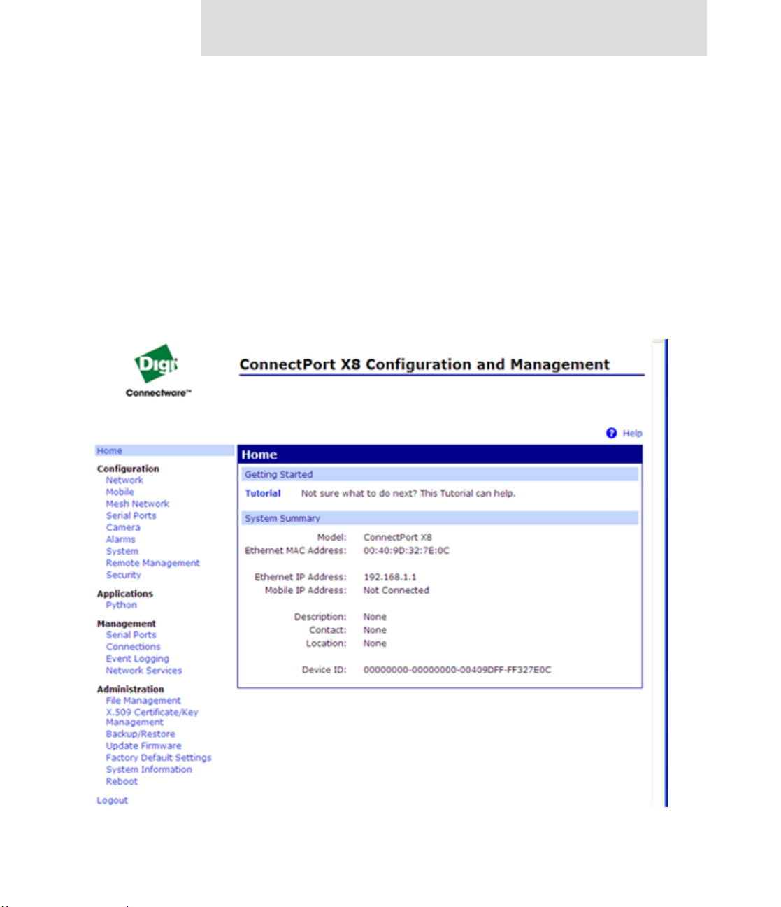
Introduction
The Web interface
A web interface is provided as an easy way to configure and monitor Digi devices.
Configurable features are grouped into several categories. These categories vary by
product; examples include Network, Serial Port, Alarms, System, Remote Management,
Security . Most of the configurable features are arranged by most basic set tings on a pa ge,
with associated and advanced settings accessible from that page. As in th e Digi Dev ice
Setup Wizard, seria l-p ort co nfigu rations are classified into port profiles, or configuration
scenarios that best represents the environment in which the Digi device will be used.
Selecting a particular port profile configures the serial port parameters that are nee ded.
For some features, it may be desirable to establish a basic configuration using the Digi
Device Setup Wizard, and then fine-tune th e configuration using the web interface.
53
Page 54

Configuration capabilities and interfaces
Advantages of the web interface include
Ease of use, including point-and-click functionality and wizards that make
configuration quick and complete.
Secure access to devices.
No need for programming experience.
Port profiles simplify the configuration process.
A potential disadvantage of the web in terface is that not all settings provided by the
command-line interface are displayed. However, the configuration settings in the web
interface should be sufficient for most users. If necessary, settings can be modified later
from the command line.
To access the web interface, enter the Digi Cellular Family device’s IP address or host
name in a browser’s URL window. The main men u of the web interface is displayed.
For more information, see "Configuration through the web interface" on page 68.
The web interface has a tutorial, accessed from the Home page, and online he lp , accessed
from the Help link on each page.
54
Page 55

Introduction
Command-line interface
Digi devices can be configured by issuing commands from the command line. The
command-line interface allows communication directly without a graphical interface. For
example, the following is a command issued from the command line to assign the IP
address to the Ethernet interface:
#> set network ip=192.168.1.1
Advantages of the command-line interface include:
Flexibility. Although the command-line Interface is for experienced users and
considered complex, it allow s flexibility for precise configuration alterations.
Direct communication to device or system.
Disadvantages of the command-l ine interface include:
Users must have experience issuing commands.
Command documentation is required.
The command line allows the greatest flexibility to configure Digi devi ces, but
is also considered complex.
The command line is available through Telnet or SSH TCP/IP connections, or through
serial port using terminal emulation software such as Hyperterminal. Access to the
command line from serial ports depends on the port profile in use by the port. By default,
serial port command-line access is allowed.
See "Configuration through the command line" on page 166 for more information on this
interface. See the Digi Connect Family Command Reference for command descriptions
and examples of entering configuration commands from the command-line interface. In
addition, online help is available for th e commands, through the help and ‘?’ commands.
55
Page 56

Configuration capabilities and interfaces
Connectware Manager interface
Connectware Manager is an optional, centralized device and network management
package. From the Connectware Manager interface, you can:
Configure devices
Remotely upgrade device firmware
Remotely reboot devices
Reset devices to factory defaults
Backup/restore device configuration properties
Import or export the device configuration properties.
Track devices
Monitor devices and connections
Set filters and send alarms
Collect and analyze traffic information
Manage the Connectware Manager server, including shutting down, stopping,
restarting, and reconfiguring the server, and displaying reports and logs on
server activity.
56
Page 57

Introduction
Advantages of the Connectware Manager interface are:
Allows multiple devices to be managed (configured and monitored) from one
source. This multiple-device, network-view capabil ity is pa rticu larly use ful for
Cellular and ConnectPort X products.
The server can also be managed from same location.
Logs and reports can be generated and reviewed. Summaries or totals can be
linked back to the original devices for more thorough investigations.
Disadvantages include:
Devices must be provisioned (assigned an IP address) before they can be
accessed on Connectware Manager. Use the Digi Device Setup Wizard to
provision devices.
If used to manage a device, some of the device configuration options that are
available on other device configuration interfaces, such as the web an d
command-line interfaces, will not be available.
To mi nimize network traffic, Connectware Manager uses caching. As a result,
device settings can be out-of-sync between the device and the settings view ed
on the Connectware Manager console.
Connectware Manager requires a dedicated computer to act as a Connectware
Manager server.
For more information on Connectware Manager as an remote management interface, see
these resources:
"Configure remote management (Connectware Manager) settings" on page
154. This section shows how to configure Connectware Management settings
within Digi devices.
"Configuration through Connectware Manager" on page 170.
"Monitoring capabilities from Connectware Manager" on page 206
Connectware Man a ger Ge tti ng Started Guide
57
Page 58

Configuration capabilities and interfaces
Simple Network Management Protocol (SNMP)
Simple Network Management Protocol (SNMP) is a protocol for managing and
monitoring network devices. The SNMP architecture enables a network administrator to
manage nodes--servers, workstations, routers, switches, hubs, etc.--on an IP network;
manage network performance, find and solve network problems, and plan for network
growth. Digi Cellular Family products support SNMP Version 1.
Advantages of SNMP include:
SNMP is easy to implement in extensive networks.
Programming new variables is easy.
SNMP is widely used. SNMP is a standard interface that integrates well with
network management stations in an enterprise environment. While its
capabilities are limited to device monitoring and display of statistics in Digi
Cellular Family devices, read/write capabilities are expected to be added to
Digi Cellular Family devices in future releases.
It is easy to ‘drop in’ new devices.
Disadvantages include:
58
As device communication is UDP-based, the communication is not secure. If
more secure communications with a device are required, an alternate interface
must be used.
SNMP does not allow for certain task that can be performed from the web
interface, such as file management, uploading firmware, or backing up and
restoring configurations.
Compared to the web or command-line interfaces, SNMP is limited in its
ability to set specific parameters, such as set port profile, is not possible.
Accessing the SNMP interface requires a tool, such as a network management station. The
management station relies on an agent at a device to retrieve or update the information at
the device, including Device configuration, status, and statistical information. This
information is viewed as a logical database, called a Management Information Base
(MIB). MIB modules describe MIB variables for a variety of device types and computer
hardware and software components.
Page 59

Introduction
Standard MIBs supported
The standard MIBs supported in Digi Cellular Family devices are:
MIB-II (RFC 1213) This is a MIB for managing a TCP/IP network. It is an
update of the original MIB, now called MIB-I. MIB-II contains variable
definitions that describe the most basic information needed to manage a TCP/IP
network. These variable definitions are organized into several groups, such as
groups for managing the system, network interfaces, address translation,
transmission media, and various protocols, including IP, ICMP, TCP, UDP,
EGP, and SNMP.
CHARACTER-MIB (RFC 1658)
RS-232-MIB (RFC 1659).
Digi enterprise MIBs supported
In addition to the standard MIBs, Digi devices use several Digi enterprise MIBs,
including:
DIGI-DEVICE-INFO.mib: for handling device information. This MIB gives
access to elements like the firmware revision, device name, IP network
information, memory, and CPU statistics.
DIGI-SERIAL-ALARM-TRAPS.mib: for handling alarms sent as SNMP trap s.
Additional SNMP resources
A variety of resources about SNMP are available, including reference books, overviews,
and other files on the Internet. For an overview of the SNMP interface and the
components of MIB-II, go to www.rfceditor.org, and search for MIB-II. From the
results, locate the text file describing the SNMP interface, titled Mana gement Informat ion
Base for Network Management of TCP/IP-based internets: MIB-II. The text of the Digi
enterprise MIBs can also be displayed.
For additional discussion of using SNMP as a device monitoring interface, see
"Monitoring Capabilities from SNMP" on page 208.
59
Page 60

Monitoring capabilities and interfaces
Monitoring capabilities and interfaces
There are several capabilities and interfaces for monitoring Digi devices and managing
their connections; these are covered in more detail in Chapter 3, "Monitor and manage
Digi devices".
Monitoring Digi devices includes such tasks as checking device status, checking runtime
state, viewing serial port operations, and reviewing network statistics, and managing their
connections.
Monitoring interfaces
As with device configuration, there are several interfaces available for monitoring Digi
devices, including:
The web interface embedded with the product
SNMP
The command-line interface
60
Connectware Manager
Web Interface
The web interface has several screens for monitoring Digi devices:
Network Status
Mobile connection status
Serial Port Management: for each port, the port’s description, current profile,
and current serial configuration.
Connections Management: A display of all active system connections.
Page 61

Introduction
System Information:
– General device information
– Serial port information: for each port, the port’ s description, current profile, and
current serial configuration. This is the same information displayed by
choosing Serial Port Management.
– Network statistics: statistics for IP, TCP, UDP, and ICMP
Command-line interface
Several commands can be issued from the command line to monitor devices. For a review
of these commands and what they can provide from a device-monitoring perspective, see
"Monitoring capabilities from the command line" on page 198.
Connectware Manager
In the Connectware Manager interface, monitoring capabilities can be sorted by t he server
and the devices managed by the server. The information is available in logs and can be
generated into reports. When available, the reports post linked totals that can be drilled
back to the original devices that make up the activity of the report.
Connectware Manager is well-suited to managi ng Cellular and ConnectPort X Family
devices and the networks in which the devices reside. Advantages include:
The ability to view an entire network, and multiple networks, at once
Easy to view signal strength, link quality, and alarms
SNMP
Monitoring capabilities of SNMP include managing network performance, gathering
device statistics, and finding and solving network problems. For more in formation on
using SNMP for device-monitoring purposes, see "Monitoring Capabilities from SNMP"
on page 208.
61
Page 62

Administration tasks
Administration tasks
Periodically, administrative tasks need to be performed on Digi devices, such as:
Uploading and managing files
Changing the password for logging onto the device
Backing up and restoring the configuration
Updating firmware
Restoring the configuration to factory defaul ts
Rebooting the module
As with configuration and monitoring tasks, administrati on can be done from a number of
interfaces, including the web interface, command line, and Connectware Manager. See
Chapter 4, "Administration tasks" for more information and procedures.
62
Page 63

Configure Digi devices
CHAPTER 2
This chapter describes how to configure a Digi device. It covers these topics:
"Default IP address" on page 64, identifying the predefined static IP address for
your Digi device.
"Alternate methods for assigning an IP address" on page 64
"Configuration through the web interface" on page 68.
"Configuration through the command line" on page 166.
"Configuration through Simple Network Management Protocol (SNMP)" on
page 169.
"Batch capabilities for configuring multiple devices" on page 174.
The primary focus of this chapter is on configuring Digi devices through the web
interface. To use the Digi Device Setup Wizard for initial configuration, see the online
help for the Wizard. For instructions on launching the wizard, see "Configure an IP
address using the Digi Device Setup Wizard" on page 64.
63
Page 64

Default IP address
Default IP address
ConnectPort X Family products ship with a a default static IP address for the Ethernet
port of 192.168.1.1 and a a DHCP server enabled by default. Therefore, simply
connecting a laptop computer to the Ethernet port of these products allows direct a ccess to
the web interface for configuration.
Alternate methods for assigning an IP address
There are several alternate ways to assign an IP address to a Digi device:
Using the Digi Device Setup Wizard.
Using Dynamic Host Configuration Protocol (DHCP) from the web interface.
Using the command-line interf ace.
Using Automatic Private IP Addressing (APIPA), also known as Auto-IP.
Configure an IP address using the Digi Device Setup Wizard
The Digi Device Setup Wizard is supplied on the Software and Documentation CD. Using
this wizard is the easiest way to assign an IP address and initially configure Digi devices.
It discovers Digi devices on a network, configures an IP address, and configures basic
serial port parameters according to how the device will be used. After this initial
configuration, features can be fine-tuned as needed through the web interface. Setup is
specially designed for the Windows environments, and is quick, automated, and complete.
To use the Digi Device Setup Wizard:
1 Connect the Digi deviceto the network and power it on.
2 Locate the MAC ad dress for the Digi device; it is on a label on the bottom of the
product. Record it for later use in assigning an IP address.
3 Insert the Digi CD in the CD drive of a computer running Microsoft Window. If the
CD does not start automatically, double-click
My Computer > CD ROM Drive > setup.exe.
64
Page 65

4 The Digi Device Setup Wizard automatically starts. Select the appropriate platform
and click Next.
The Digi device discovery utility finds and lists all of the Digi devices on the
network.
5 L oc a t e the Digi device by its MAC addres s.
6 Select the Digi device and click Next.
7 Follo w the in struc t ions in the wi za rd to assig n an IP address for th e Digi device.
Use the online help supplied with the wizard for information about values and
selections on the wizard screens.
Configure an IP address using DHCP
A IP address can also be configured u sing Dynamic H ost Configuration Protocol (DHCP).
If desired, set up a permanent entry for the Digi device device on a DHCP server. While
this is not necessary to obtain an IP address via DHCP, setting up a permanent entry means
the IP address is saved when the device is rebooted. For more info rmation on DHCP
server configuration, see "DHCP server settings" on page 77.
Configure Digi devices
Configure an IP address using Auto-IP
The standard protocol Automatic Private IP Addressing (APIPA or Auto-IP) assigns the
IP address from the reserved IP addresses in Auto-IP. Use ADDP or DH CP to find the
device and assign it a new IP address that compatible with your network. Once the un it is
plugged in, Auto-IP automatically assigns the IP address.
65
Page 66

Alternate methods for assigning an IP address
Configure an IP address from the command-line interface
The set network command configures an IP address from the command line. Include the
following parameters:
ip=device ip: The IP address for the device.
gateway=gateway: The network gateway IP address.
submask=device submask: The device subnet mask.
dhcp=off: Turns of f use o f th e Dynamic Host Co nfigurat ion Prot ocol (D HCP),
so that the IP address assigned is permanent.
static=on: Specifies that the IP address is static, and will remain as the
specified IP address, gateway, and submask.
For example:
set network ip=10.0.0.100 gateway=10.0.0.1
submask=255.255.255.0 dhcp=off static=on
IP addresses and Connectware Manager
66
The Connectware Manager interface can only change the Ethernet/LAN address for a Digi
device. The mobile/cellular device is typically provided by the mobile service provider;
check with your mobile service provider on how they handle addresses. To change the IP
address, open the web interface for based on the IP address the device has and navigate to
Configuration > Network > IP Settings. On the IP Settings page, enter the new IP
address, subnet mask, and gateway.
T o use Connectware Manager , first configure the Digi device using the Digi Device Setup
Wizard, then inst al l Connectware Manager. For more information, see the Connectware
Manager Operator’s Guide.
Page 67

Test the IP address configuration
Once the IP address is assigned, test the IP address configuration to be sure it works as
configured. This procedure assumes that the Digi device has an IP address.
1 Access the command line of a PC or other networked device.
2 Issue the following command:
ping ip-address
where ip-address is the address assigned to the Digi device. For example:
ping 192.168.2.2
Configure Digi devices
67
Page 68

Configuration through the web interface
Configuration through the web interface
Configuring Digi devices through the web interface involves these tasks:
Change the IP address, as needed. See page 74.
Open the web interface. See page 69.
Configure network communications. See page 75.
Configure mobile (cellular) settings, including provisioning the Digi Cellular
Family device, mobile service provider settings, mobile connect ion settin gs,
and SureLink settings. See page 119.
Configure Mesh network settings. See page 130.
Configure the serial ports. See page 137.
Configure camera settings.
Configure alarms. See page 149.
Configure security/user features such as user names and password
authentication. See page 160.
68
Configure system-identifying information and the settings for Simple Network
Management Protocol (SNMP). See page 153.
Configure remote management using a Connectware Manager server. See
page 154.
Configure and run applications available for use. Su pported applications vary.
See page 164.
– For ConnectPort X Family products, manage pr ograms authored in the
Python
®
programming language. See page 164.
Page 69

Open the web interface
T o open the web interface, either enter the Digi device’s URL in a web browser and log on
to the device, if required, or use the Digi Device Discovery utility to locate it and open its
web interface.
By entering the Digi device’s IP address in a web browser
1 In the URL address bar of a web browser, enter the IP address of the device.
2 If security has not been enabled for the Digi device, the Home page of the web
interface is displayed. If secu rit y has bee n enabl ed for th e Digi device, a login
dialog will be displayed. Enter the user name and password for the device. The
default username is root and the default password is dbps. If these defaults do not
work, contact the system administrator who set up the device. Then the Home page
of the web interface is displayed. See "Organization of th e web in terface" on page
71 for an overview of using the Home page and other linked pages.
Note
Configure Digi devices
The idle timeout automatically logs users out of the web interface after 5
minutes of inactivity if password authentication has been enabled for the
device.
By using the Digi Device Discovery utility
Alternatively, use the Digi Device Discovery Utility to locate the Digi device and open its
web interface.
Install Digi Device Discovery utility
The Digi Device Discovery Utility is available on the Software and Documentation CD. If
this utility is not already available on your computer, follow these steps.
1 On th e main page Software and Documentation CD, click software - install
optional software.
2 Select Device Discovery Utility an d clic k Install.
3 Follow the prompts of the Setup Wizard to install t he Digi De vice Discove ry Utility
software.
69
Page 70

Configuration through the web interface
Discover devices
From the start menu, select Start > Programs > Digi Connect > Digi Device Discovery.
The Digi Device Discovery application is displayed.
Locate the device in the list of devi ces, and double-click it, or select the Digi device from
the list and select Open web interface in the Device Tasks list.
70
4 Depending on whether a system ad min istrator has configured password
authentication for the device, a login may be required. If a login dialog is displayed,
enter the user name and password for the Digi device . The defau lt username is root
and the default password is dbps. If these defaults do not work, contact the system
administrator who initially set up the device. Now configure the Digi device, as
described on the following pages.
Page 71

Organization of the web interface
When web interface is opened, the Home page is displayed.
Here is a home page for a ConnectPort X Family product.
Configure Digi devices
71
Page 72

Configuration through the web interface
The Home page
The left side of the Home page has a menu of choices that display pages for configuration,
management, and administration tasks, and to log out of the web interface. This chapter
focuses on the choices under Configuration and Application. For details on monitoring
Digi devices and the choices under Management, see Chapter 3, "Monitor and manage
Digi devices". For details on the tasks under Administration, see Chapter 4,
"Administration tasks".
Clicking Logout logs out of a configuration and management session with a Digi device.
It does not close the browser window, but displays a logout window. To finish lo gging out
of the web interface and prevent access by other users, close the browser window . Or, log
back on to the device by clicking the link on the screen. After 5 minutes of inactivity, the
idle timeout also automatically performs a user lo gout.
The Getting Started section has a link to a tutorial on configuring and managing Digi
device.
The System Summary section notes all available device-description information.
Configuration pages
72
The choices under Configuration in the menu display pages for configuring settings for
various features, such as network settings, mobile settings, and serial port settings.
Some of the configuration settings are organized on sets of linked screens. For example,
the Network Configuration screen initially di splays the IP Settings, and provides links to
Network Services Settings, Advanced Settings, and other network settings appropriate to
the Digi device.
Page 73

Configure Digi devices
Application pages
Depending on the Digi device, there may be an Application menu item for configuring
various applications available for use in the device.
Python: For loading and running custom programs authored in the Python
programming language onto ConnectPort X Family devices.
Apply and save changes
The web interface runs locally on the device, which means that the interface always
maintains and displays the latest settings in the Digi device.
On each screen, the Apply button is used to save any changes to the configuration sett ings
to the Digi device.
Cancel changes
To cancel changes to configuration settings, click the Refresh or Reload button on the
web browser . This causes the browser to reload the page. Any changes made since the last
time the Apply button was clicked are reset to their original values.
Restore the Digi device to factory defaults
The device configuration can be reset to factory defaults as needed during the
configuration process. See "Restore a device configuration to factory defaults" on page
215.
Online help
Online help is available for all screens of the web interface, and for common configuration
and administration tasks. There is also tutorial available on the Home page.
73
Page 74

Configuration through the web interface
Change the IP address from the web interface, as needed
Normally, IP addresses are assigned to Digi devices either through DHCP or the Digi
Device Setup Wizard.
This procedure assumes that the Digi device already has an IP address and you simpl y
want to change it.
1 Op en a web browser and enter the Digi device’s current IP address in the URL
address bar .
2 If security is enabled for the Digi device, a login prompt is displayed. Enter the u ser
name and password for the device. The default username is root and the defau lt
password is dbps. If these defaults do not work, contact the system administrator
who set up the device.
3 Cl ick Network to access the Network Configuration page.
4 On the IP Settings page, select Use the following IP address.
5 Enter an IP address (and other network settings), then click Apply to save the
configuration.
74
Page 75

Configure network communications
The Network configuration pages include:
IP Settings: For viewing IP address settings and changing as needed. See
page 76.
DHCP Server Settings: For configuring a DHCP server to allow other devices
or hosts on this network to be assigned dynamic IP addresses. See page 77.
Network Services Settings: Enable and disables access to various network
services, such as ADDP, RealPort and Encrypted RealPort, Telnet, HTTP/
HTTPS, and other services. See page 82.
Dynamic DNS Update Settings: For configuring a Dynamic DNS (DDNS)
service that allows a user whose IP address is dynamically assigned to be
located by a host or domain name. See page 87.
IP Filtering Settings: For configuring the Digi Cellular Family devi ce to on ly
accept connections from specific and known IP addresses or networks. See
page 90.
IP Forwarding Settings: For configuring the Digi Cellular Family device to
forward certain connections to other devices. This is also known as Network
Address Translation (NAT) or Port Forwarding. See page 91.
Configure Digi devices
Socket Tunnel Settings: For configuring a socket tunnel, used to connect two
network devices: one on the Digi Cellular Family device’s local network and
the other on the remote network. See page 93.
Virtual Private Network (VPN) Settings: For configuring Virtual Private
Networks, which are used to securely connect two private networks together so
that devices may connect from one network to the other network using secure
channels. See page 99.
IP Pass-through Settings: Configures a Digi Cellular Family device to pass its
mobile IP address directly through and to the Ethernet device (router or PC) to
which it is connected through the Ethernet port. The Digi Cellular Family
device becomes transparent (similar to the behavior of a c able o r DSL mod em)
to provide a bridge from the mobile network directly to the end device atta ched
to the Digi Cellular Family device. See page 94.
Advanced Network Settings: Configures the Ethernet Interface speed and
mode, TCP/IP settings, TCP keepalive settings, and DHCP settings. See
page 118.
75
Page 76

Configuration through the web interface
Alternatives for configuring network communications
There are three ways a Digi devicecan be configured on the network.
Using dynamic settings: All network settings will be assigned automatically
by the network, using a protocol called DHCP. Contact your network
administrator to find out if a DHCP server is available.
Using static settings: All network settings are set manually and will not
change. The IP address and Subnet Mask are mandatory. The rest are not
mandatory, but may be needed for some functions. Contact your network
administrator for the required values.
Using Auto-IP: Auto-IP assigns an IP address to the Digi device immediately
after it is plugged in. If running DHCP or ADDP, the Au to-IP address is
overridden and a network compatible IP address is assigned, or a static IP
address can be assigned.
Digi Cellular Family products have two IP addresses: one for Ethernet and one for
cellular. All Digi Cellular Family products except Digi Connect WAN IA have a predefined default Ethernet Port IP address of 192.168.1.1.
76
Even if a DHCP server is available, the device configuration may work better with static
settings. Once set, static settings will not change, so you and other network devices can
always find the Digi deviceby its IP address. W ith dyn amic settings, the DHC P server can
change the IP address. This can ha ppen frequ ently or infreq uently depen ding on h ow your
network administrator has configured the netwo rk.
When the IP address does change, you and other network devices configured to talk to the
Digi devicecan no longer access the device. In this case, the Digi device must be located
the Digi Device Discovery utility, and other network devices that need to communicate
with the Digi device must be reconfigured.
IP settings
The IP Settings page shows how the IP address of the Digi deviceis obtained, either by
DHCP or by using a static IP address, subnet mask, default gateway . In additi on, this pag e
shows IP addresses of the primary and secondary Domain Name System (DNS) server for
the Digi device. Contact your network administrator for more information about these
settings, and see the online help.
Page 77

Configure Digi devices
DHCP server settings
The DHCP server feature can be enabled in a Digi device to allow other devices or hosts
on this network to be assigned dynamic IP addresses. This DHCP server supports a single
subnetwork scope.
For the DHCP server to operate, the Digi device must be configured to use a static IP
address. For information on how to configure static IP settings, see "IP settings" on page
76.
The Digi Connect WAN IA has different factory defaults for DHCP server. The DHCP
server is disabled, and DHCP Client enabled.
For information on how to manage the DHCP server, see "Manage DHCP server
operation" on page 190.
DHCP terminology
Some key DHCP terms involved in configuring a DHCP server include:
scope
A scope is the full consecutive range of possible IP addresses for a network. A scope
typically defines a single physical subnet on your network, to which DHCP services are
offered. A scope is the primary way for the DHCP server to manage distribution and
assignment of IP addresses and related configuration parameters to its clients on the
network.
exclusion range
An exclusion range is a limited sequence of IP addresses within a scope, excluded from
DHCP service offerings. Exclusion ra nges assure that any addresses in these ranges are
not offered by the server to DHCP clients on your network.
address pool
After the scope is defined and exclusion ranges are applied, the remaining addresses
form the available address pool within the scope. The addresses in this pool are
available for dynamic assignment by the server to DHCP clients on your network.
77
Page 78

Configuration through the web interface
lease
A lease is the length of time that the DHCP server specifies, during whic h a client host
can use an assigned IP address. When the DHCP server grants a lease to a client, the
lease is active. Before the lease expires, the client typically needs to renew its address
lease assignment with the DHCP server. A lease becomes inactive when it expires or it
is deleted at the server, or if the client actively releases the l ease. The duration of a lease
determines when it will expire and how often the client needs to renew it wi th the DHCP
server in order to retain the lease.
A DHCP server will never grant a lease to its own address. There is no need for its ow n
address to be in the exclusion range; the DHCP server simply protects its address from
being offered.
grace period
When a DHCP client actively releases a lease, or when the lease expires without being
renewed by the client, the DHCP server does not immediately delete the lease record
and return the associated IP address to the available address pool. A grace period is the
interval of time for which the lease record is retained before the DHCP server
automatically deletes the record from its lease list, thereby making the IP address
available for lease assignment to another client. The grace period is not a configurable
value. See also the discussion of the grace period and what it means when the DHCP
server is running in "View and manage current DHCP leases" on page 191.
78
reservation
You may use a reservation to create a permanent address lease assignment by the DHCP
server. Reservations assure that a specified hardware device on the subnet can always
use the same IP address. Address lease reservations associate a specific IP address with
a specific client's Ethernet MAC address.
options
Options are other client configuration parameters that the DHCP server can assign when
serving leases to DHCP clients. Most options are de fined in RFC 2132. The DHCP
server in Digi device supports a limited set of options:
– Option 3: Routers on Subnet
– Option 6: DNS Servers
Page 79

Configure Digi devices
Addresses in the DHCP server settings
The IP address and subnet mask of the DHCP server's scope are the static IP configuration
settings for the Digi device itself.
The default gateway (router) provi ded to a client with the lease information is the IP
address of the Digi device.
The DNS servers provided to a client with the lease information are the DNS server
addresses configured in the Digi device. These addresses include any DNS server
addresses that the Digi device acquires when it connects to the mobile network.
DHCP server configuration settings
Here are the configuration settings for the DHCP server. Typically, these settings can be
modified without having to restart the DHCP server for the changes to become effective in
the running server.
Enable Dynamic Host Configuration Protocol (DHCP) Server: Enables the
DHCP server feature on this Digi device. Note that for the DHCP server to
operate, the Digi device must be configured to use a static IP address. For
information on how to configure static IP settings, see "IP settings " on pa ge 76 .
IP Addresses: The starting and ending IP addresses for the scope being served
by this DHCP server. These addresses must be in the same subnet as the Digi
device itself.
Lease Duration: The length of the leases for the scope being served by this
DHCP server. The default lease duration is 24 hours. A DHCP client may
request a lease duration other than this setting, and the DHCP server will grant
that request if possible.
Wait specifie d delay before sending DHCP offer reply: The interval of time
in milliseconds to delay before offering a lease to a new client. The default
delay is 500ms, and the range is 0 to 5000ms. Use of this delay permits this
Digi device to reside on a network with other DHCP servers, yet not offer
leases to new clients unless the other DHC P serve rs do no t make such an offer.
This provides a measure of protection against inadvertently connecting a Digi
device to a network that is running its own DHCP server(s), and offering leases
to clients in a manner inconsistent with that network.
79
Page 80

Configuration through the web interface
Check that an IP address is not in use before offering it: When a DHCP
client requests a new IP address lease, before offering an IP address to that
client, use “ping” to test whether that IP address is already in use by another
host on the network but is unknown to the DHCP server. If an IP address is
determined to be in use, it is marked as Unavailable for a period of time, and it
will not be offered to any client while in this state. Enabling this test adds
approximately one second of delay before the IP address is offered to the client,
since the “ping” test must not receive a valid reply for that test to successfully
determine that the IP address is not already in use. This option is off (disabled)
by default. This option does not apply to Static Lease Reservations, since the
“ping” test is not used for them.
Static Lease Reservations: A static lease reservation is a specific IP address
paired with a client's MAC address, which reserves the IP address for that
client's use only. This assures that a client always receives a lease for the same
IP address and that no other client obtains a lease for that address.
To add a reservation, enter the IP Address and MAC Address values, check or
clear the Enable checkbox, and then press the Add button.
After adding a reservation, you may click on the IP address or MAC address of
that entry in the table, permitting you to speci fy or modify the lease duratio n for
this reservation.
80
The Enable checkbox for the en try permits a reservation to be disabled without
actually removing the entry, then enabled again at a later time.
The Remove link is used to permanently remove a re servation from the DHCP
server configuration.
The Remove All link is used to permanently remove all reservations from the
DHCP server configuration.
Page 81

Configure Digi devices
Address Exclusions: A specific set of IP addresses to exclude from the scope.
The DHCP server will not grant leases to clients for any IP address in the
exclusion range.
To add an exclusion, enter the starting and ending IP Addresses, check or clear
the Enable checkbox, and then press the Add button.
The Enable checkbox for the entry permits an exclu sion to be disabl ed without
actually removing the entry, then enabled again at a later time.
The Remove link is used to permanently remove an exclusion from th e DHCP
server configuration.
The Remove All link is used to permanently remove all exclusions from the
DHCP server configuration.
Apply button: You must click the Apply button to save changes you make to
the DHCP server settings. If you leave this page without applying th e cha ng es,
those changes will be discarded.
Manage the DHCP server
For information on managing the DHCP server and viewing and managing lease status,
see "Manage DHCP server operation" on page 190.
81
Page 82

Configuration through the web interface
Network services settings
The Network Services page shows a set of common network services th at are available for
Digi devices, and the network port on which the service is running.
Common network services can be enabled and disabled, and the TCP port on which the
network service listens can be configured. Disabl ing services may be done for security
purposes. That is, certain services can be disabled so the device runs only those services
specifically needed. T o improve device security, non-secure services such as T elnet can be
disabled.
It is usually best to use the default network port numbers for these services because they
are well known by most applications.
Several services have a setting for whether TCP keep-alives will be sent for the network
services. TCP keep-alives can be configured in more detai l o n th e Advanced Network
Settings page.
Caution
Exercise caution in enabling and disabling network services,
particularly disabling them. Changing certain settings can render a
Digi Connect device inaccessible. For example, disabling Advanced
Digi Discovery Protocol (ADDP) prevents the device from being
discovered on a network, even if it is actually connected. Disabling
HTTP and HTTPS disables access to the web interface. Disabling
basic services such as Telnet, Rlogin, etc. can make the CommandLine interface inaccessible.
82
Page 83

Configure Digi devices
Supported network services and their default network port numbers
In Digi devices that have multiple serial ports, the network port number defaults for
various services are set based on the following formula:
base network port number + serial port number
For example, the Telnet Passthrough service is set to network port 2001 for serial port 1,
2002 for serial port 2, 2003 for serial port 3, etc.
If a network port is changed for a particular service, that is the only network port number
that changes. That change does not carry over to the other network ports. For example, if
the network port number for Telnet Passthrough is changed from 2001 to 3001, that does
not mean that the other network ports will change to 3002, 3003, etc.
There are two types of network services available:
Basic services, which are accessed by connecting to a particular well-known
network port.
Passthrough services, in which a particular serial port is set up for a particular
type of service. To use the service, users must both use the correct protocol and
specify the correct network port. For example, assuming default service ports
and using a Linux host, here is how a user would access the SSH and Telnet
passthrough services:
#> ssh -l fred digi16 -p 2501
#> telnet digi16 2101
83
Page 84

Configuration through the web interface
The following table shows the network services, the services provided, and the default
network port number for each service.
Service Services provided Default
network
port
number
Device Discovery, also known as
Advanced Digi Discover y Protocol
(ADDP)
Encrypted (Secure) RealPort Secure Ethernet connections between COM or TTY ports
Line Printer Daemon (LPD) Allows network printing over a serial port. 515
Modem Emulation Pool (pmodem) Allows the Digi device to emulate a modem. Modem
Modem Emulation Passthrough Allows the Digi device to emulate a modem. This service is
RealPort A virtual connection to serial devices, no matter where they
Discovery of Digi devices on a network. Disabling this
service disables use of the Digi Device Discovery utility to
locate the device, either on its own or as part of running the
Digi Device Setup Wizard.
The network port number for ADDP cannot be changed
from its default.
and device servers or terminal servers.
emulation sends and receives modem responses to the serial
device over the Ethernet instead of Public Switched
Telephone Network (PSTN). Telnet processing can be
enabled or disabled on the incoming and outgoing modememulation connections. The pmodem service is for
connecting to whatever serial port will answer.
for dialing in to a particular serial port that has been set up
for modem emulation.
reside on the network.
2362
1027
5000
5001
771
Remote login (Rlogin) Allows users to log in to the Digi device and access the
command-line interface through Rlogin.
Remote shell (Rsh) Allows users to log in to the Digi device and access the
command-line interface through Rsh.
84
513
514
Page 85

Configure Digi devices
Service Services provided Default
network
port
number
Secure Shell (SSH) Allows users secure access to log in to the Digi device and
access the command-line interface.
Secure Shell (SSH) Passthrough Accessing a specific serial port set up for SSH. 2501
Secure Socket Service Authentication and encryption for Digi devices. 2601
Simple Network Management Protocol
(SNMP)
Telnet Server Allows users an interactive Telnet session to the Digi
Telnet Passthrough Allows a Telnet connection directly to the serial port, often
Transmission Control Protocol (TCP)
Echo
Managing and monitoring the Digi device.
To run SNMP in a more secure manner, note that SNMP
allows for “sets” to be disabled.This securing is done in
SNMP itself, not through this command.
If disabled, SNMP services such as traps and device
information are not used.
device’s command-line interface.
If disabled, users cannot Telnet to the device.
referred to as reverse Telnet.
Used for testing the ability to send and receive over a TCP
connection, similar to a ping.
22
161
23
2001
7
Transmission Control Protocol (TCP)
Passthrough
User Datagram Protocol (UDP) Echo Used for testing the ability to send and receive over a UDP
User Datagram Protocol (UDP)
Passthrough
Allows a raw socket connection directly to the serial port,
often referred to as reverse sockets.
connection, similar to a ping.
Allows raw data to be passed between the serial port and
UDP datagrams on the network.
2101
7
2101
85
Page 86

Configuration through the web interface
Service Services provided Default
network
port
number
Web Server, also known as HyperText
Transfer Protocol (HTTP)
Secure Web Server, also known as
HyperText Transfer Protocol over Secure
Socket Layer (HTTPS)
Network services and IP pass-through
The IP pass-through feature (Configuration > Network > IP Pass-through) causes the
Digi device to be bridged transparently between the Eth ernet and mobile data links.
Enabling IP Pass-through disables many device feat ures, including many network
services. T o provide ac cess to the device for configura tion and management purposes, you
can configure a subset of network services to terminate at the Digi device instead of being
passed on to a connected device such as a router. In the IP pass-through feature, these
network services are called pinholes. Services that can be configured as pinholes include
HTTP, HTTPS, Telnet, SSH, and SNMP. See "IP pass-through settings" on page 94 for
more information.
Access to web pages for configuration that can be secured
by requiring a user login.
HTTP and HTTPS, below, are also referred to as Web
Server or Secure Web Server. These services control the use
of the web interface. If HTTP and HTTPS are disabled,
device users cannot use the web interface to configure,
monitor, and administer the device.
Access to web pages for configuration that can be secured
by requiring a user login, with encryption for greater
security.
80
443
86
Page 87

Configure Digi devices
Dynamic DNS update settings
A Dynamic DNS (DDNS) service allows a user whose IP address is dynamically assigned
to be located by a host or domain name. Before a DDNS service may be used, you must
create an account with the DDNS service provider. The provider will give you account
information such as username and password. You will use this account information to
register your IP address and update it as it changes.
A DDNS service provider typically supports the registration of only public IP addresses.
When using such a service provider , if yo ur Di gi device has a private IP address (such as
192.168.x.x or 10.x.x.x), your update requests will be rejected.
Your Digi device monitors the IP address it is assigned. It will typically update the DDNS
service or server automatically, but only when its IP address has changed from the IP
address is previously registered with that service.
DDNS service providers may consider frequent updates to be an abuse of their serv ice. In
such a circumstance, the service provider may act by blocking updates from the abusive
host for some period of time, or until the customer contacts the provider. Please observe
the requirements of the DDNS service provider to ensure compliance with possible abuse
guidelines.
The Dynamic DNS Update Settings page includes both settings and status information.
Settings
Use the following dynamic DNS service: Disables DDNS updates, or selects
the DDNS service provider to use to register the IP add ress of this Digi Cellular
Family device. When you select a specific DDNS service provider, you must
also provide the related account information for that service provider.
To fo rce an update request to be sent to a particular DDNS service.
1 Select the “None” radio button to disable DDNS updates, and then click
the Apply button to save that change.
2 Select the radio button for the DDNS service you wish to update
3 Click Apply to save that change.
If the settings for the selected DDNS service are all specified and valid, an
update request will be sent immediately to that service.
87
Page 88

Configuration through the web interface
DynDNS.org DDNS Service: You must create your account at DynDNS.org
before you can successfully register the IP address of your Digi device with
their service. Please familiarize yourself with their service options and
requirements, in order to most effectively use this feature of your Digi device.
This DDNS service supports only public IP addresses. If you have a private IP
address (such as 192.168.x.x or 10.x.x.x), your update requests will be rejected.
Host and Domain Name: The fully qualified host and domain name you have
registered with your service provider. An example is: myhost.dyndns.net.
DynDNS User Name: The user name for the account you have created with
your service provider.
DynDNS Password: The password for the account you have created with your
service provider.
DynDNS DDNS System: The system for the account you have created with
your service provider. DynDNS.org supports a number of different services,
which vary by the system you select. The available choices are:
–Dynamic DNS
– Static DNS
88
–Custom DNS
Use Wildcards: Enables/disables wildcards for this host. The available choices
for this option are:
– Disable wildcards
– Enable wildcards
– No change to service setting
According to wildcard documentation at DynDNS.org: “The wildcard aliases
*.yourhost.ourdomain.tld to the same address as yourhost.ourdomain.tld.”
Using this option in the settings for your Digi device has the same effect as
selecting the wildcard option on the DynDNS.org website. To leave the
wildcard option unchanged from the current selection on their web site, use the
“no change” option in the device settings. Note that DynDNS.org support for
this option may vary according to the DynDNS system you are registered to
use.
Connection Method: The connection method to try when connecting to your
service provider to register your IP address. DynDNS.org supports three
methods to connect. The available choices are:
Page 89

Configure Digi devices
– Standard HTTP port 80
– Alternate HTTP port 8245
– Secure HTTPS port 443
Status and history information
Following the settings are status and history information for the DDNS service.
Most Recent DDNS Service Update Status: This section provides the stat us
of the most recent attempt to update a DDNS service or server. The displayed
information confirms the success of an update request, or it may offer
information as to the reason an update request was rejected by the service or
server.
A number of status items are shown. Some of them are specific to the DDNS
service being updated. Such information will be he lp fu l when tr yin g to resolve
update failures with the DDNS service provider.
– Service: The name of the DDNS service provider or server being updated.
– IP Address Reported: The IP address for your Digi device that is being
registered with the DDNS service provider or server.
– Update Status: A simple indication of success or failure for this last update
request.
– Result Information: A DDNS service-specific status message, helpful when
consulting technical support.
– Raw Result Data: DDNS service-specific update result data returned by the
service provider, helpful when consulting technical support.
Last Logged Action or Result (may be helpful for troubleshooting): The
last attempted, logged action or result for the DDNS feature, helpful for
troubleshooting possible problems with DDNS updates. This information may
help identify problems with settings, network connection failures, and other
issues that prevent a DDNS update from being completed successfully.
Successful results also are reported here.
89
Page 90

Configuration through the web interface
IP filtering settings
You can better restrict your device on the network by only allowing certain devices or
networks to connect. This is better known as IP Filtering or Access Control Lists (ACL).
By enabling IP filtering, you are telling the device to only accept connections from
specific and known IP addresses or networks. Devices can be filtered on a single IP
address or can be restricted as a group of devices using a subnet mask that only allows
specific networks to access to the device.
Caution
It is important to plan and review your IP filtering settings before
applying them. Incorrect settings can make the Digi device
inaccessible from the network.
On the IP Filtering Settings page, enter the settings as follows:
Only allow access from the following devices and networks: Enables IP
filtering so that only the speci fied devices or netwo rks are allowed to connect to
and access the device. Note that if you enable this feature and the system from
which you are connecting to the Digi device is not included in the list of
allowed devices or networks, then you will instantly no longer be able to
communicate or configure the device from this system.
Automatically allow access from all devices on the local subnet: Specifies
that all systems and devices on the same local subnet or network of the device
should be allowed to connect to the device.
Allow access from the following devices: A list of IP addresses of systems or
devices that are allowed to connect to this device.
Allow access from the following networks: A list of networks based on an IP
address and matching subnet mask that are allowed to connect to this device.
This option allows grouping several devic es tha t exist on a particular subnet or
network to connect to the device without having to manually specific each
individual IP address.
90
Page 91

Configure Digi devices
IP forwarding settings
When a Digi device acts as a router and communicates on both a private and public
network with different interfaces, it is some times necessary to forward certain connections
to other devices. This is also known as Network Address Translation (NAT) or Port
Forwarding. When an incoming connection is made to the device on the private network,
the IP port is searched for in the table of port forwarding entries. If the IP port is found,
that connection is forwarded to another specific device on the public network.
Port Forwarding/NAT is useful when external devices can not communicate directly to
devices on the public network of the Digi devic e. For example, this may occur bec ause the
device is behind a firewall. By using port forwarding, the connections can pass through
the networks transparently. Also, Port Forwarding/NAT allows multiple devices on the
private network to communicate to devices on the public net work by using a shared
private IP address that is controlled by Port Forwarding/NAT.
Port forwarding can be used to connect from a Digi device to a RealPort device, such as a
Digi Connect SP. For this type of connection to occur, your mobile wireless provider must
be mobile-terminated.
IP Forwarding settings include:
Enable IP Routing: Enables or disables IP forwarding.
Apply the following static routes to the IP routing table: The Digi device
can be configured with permanent static routes. These routes are added to the
IP routing table when this device boots, or afterward when network interfaces
become active or changes are made to this list of static routes. The use of static
routes provides a means by which IP data grams can be routed to a network that
is not a local network or accessible through the default route.
Enable Network Address Translation (NAT): Enables or disables the use of
NAT.
91
Page 92

Configuration through the web interface
Forward protocol connections from external networks to the following
internal devices: Enables protocol forwarding to the specified internal devices.
Currently, the only IP protocols for which protocol forwarding is supported are:
– Generic Routing Encapsulation (GRE, IP protocol 47)
– Encapsulating Security Payload (ESP, IP protocol 50, tunnel mode only ).
These are routing protocols that are used to route (tunnel) various types of
information between networks. If your network needs to use the GRE or ESP
protocol between the public and private networks, enable this feature
accordingly.
Forward TCP/UDP connections from external networks to the following
internal devices: Specifies a list of connections based on a specific IP port an d
where those connections should be forwarded to. Typically the connecting
devices come from the public side of the network and are redirected to a device
on the private side of the network.
Example
For example, to enable port forwarding of RealPort data (network port 771) on a
Digi Connect WAN VPN to a Digi Connect SP with an IP address of 10.8.128.10, you
would do the following:
92
Make sure the Enable IP Routing checkbox is checked.
In the Forward TCP/UDP connections from external networks to the
following internal devices section, enter the port forwarding information as
follows, and click Add:
Page 93

Configure Digi devices
Socket tunnel settings
A Socket Tunnel can be used to connect two network devices: one on the Digi device’s
local network and the other on the remote network. This is especially useful for providing
SSL data protection when the local devices do not support the SSL protocol.
One of the endpoint devices is configured to initiate the socket tunnel. The tunnel is
initiated when that device opens a TCP socket to the Digi device device on the configured
port number . The Digi device then opens a separate connectio n to the specifie d destination
host. Once the tunnel is established, the Digi device acts as a proxy for the data between
the remote network socket and the local network socket, regardless of which end initiated
the tunnel.
Socket Tunnel settings include:
Enable: Enables or disables the configured socket tunnel.
Timeout: The timeout (specified in seconds) controls how long the tunnel will
remain connected when there is no tunnel traffic. If the timeout value is zero,
then no timeout is in effect and the tunnel will stay up until some other event
causes it to close.
Initiating Host: The hostname or IP address of the network device which will
initiate the tunnel. This field is op tional.
Initiating Port: Specify the port number that the Digi device will use to listen
for the initial tunnel connection.
Initiating Protocol: The protocol used between the device that initiates the
tunnel and the Digi device. Currently, TCP and SSL are the two supported
protocols.
Destination Host: The hostname or IP address of the destination network
device.
Destination Port: Specify the port number that the Digi device will use to
make a connection to the destination device.
Destination Protocol: This is the protocol used between Digi device and the
destination device. Currently, TCP and SSL are the two supported protocols.
This protocol does not need to be the same for both connections.
93
Page 94

Configuration through the web interface
IP pass-through settings
There are many application scenarios where a router is used to decide upon alternative
routes using a primary and a secondary (or backup) interface. In many of these
configurations, the router is required to use a public IP address as assign ed by the network
over which it is communicating. Th is requirement is mostly owing to the ro uter needing to
establish a VPN tunnel over that interface and using the public IP address as part of the
VPN authentication. (For more on VPN tunnels, see page 99.)
The IP pass-through feature allows a Digi devic e device to provide bridging functionality
similar to that of a cable or DSL modem, where the Digi device be come s “t ra nsparent” to
the router or connected device. In this case; the router’s WAN interface believes it is
connected directly to the mobile network and has no knowledge that the Digi device is the
mechanism providing that connectivity.
How IP pass-through works
A Digi device configured for IP pass-through, such as a ConnectPort WAN or Digi
Connect WAN, passes its mobile IP address directly through and to the Ethernet device
(router or PC) to which it is connected through the Ethernet port. From the perspective of
the connected device, the Digi device essentially becomes transparent (similar to the
behavior of a cable or DSL modem) to provide a bridge from the mobile network directly
to the end device attached to the Digi device.
94
Since the mobile network address is effectively “passed-through” to the local device
connected to the Ethernet port of the Digi device, all network access to it is bypassed, with
some specific exceptions.
Here is an example of a Digi device configured for IP pass-through in a network with a
third-party router.
Page 95

Configure Digi devices
If the third-party router’s WAN interface is attached to the Digi device’s Ethernet port, and
the Digi device’s mobile interface receives the IP address 166.213.2.215, the router’s
WAN port is assigned the same IP address 166.213.2.215. If the router is receiving the IP
address dynamically; the DNS server addresses, subnet mask, and default gateway
information will be filled in automatically. If the router is configured manually; you need
to obtain the DNS information from the mobile service provider and enter that manually.
The subnet mask is 255.255.255.0 and the default gateway is the same as the mobile IP
address with “.1” for the last octet. In other words: if the mobile IP address is
166.213.2.215, the default gateway is 166.213.2.1.
95
Page 96

Configuration through the web interface
How IP pass-through affects network access to Digi devices
When IP pass-through is enabled, the Digi device effectively disables all router and IP
service functionality. Services that are disabled are:
NAT
Port Forwarding
VPN
DDNS updates
Socket Tunnel
Network Services configuration.
The Digi device is effectively transparent to all IP activity and network access by other
devices, with these exceptions:
It can be accessed via the serial port for configuration using the command line
interface.
It accepts TCP/IP connections for purposes of configuration by means of a
“pinhole” on the mobile interface.
96
It can be accessed by other devices on the local Ethernet segment via the
default IP address of 192.168.1.1.
Using pinholes to manage the Digi device
IP pass-through uses a concept called pinholes. The Digi device can be configured to
listen on specific TCP ports, and terminate those connections at the Digi device for
purposes of managing it. Those ports are called pinholes, and they are not passed on to the
device connected to the Ethernet port of the Digi device. Network services and ports that
can be configured as pinholes include (see "Network services settings" on page 82 to
configure these settings):
Telnet: for accessing the device through a Telnet login and the command-line.
SSH: for accessing to the device through a Secure Shell (SSH) login and the
command-line.
HTTP: for accessing the device through HTTP and the web interface.
HTTPS: for accessing to the device through HTTPS and the web interface
SNMP: for monitoring and managing the device through SNMP.
Page 97

Configure Digi devices
Connectware Manager and Digi SureLink ports are automatically set up as pinholes so
that they continue to work with the Digi device. In addition, the Digi device uses a private
address on the Ethernet interface strictly for use in configuration or local access. This
allows a user on the local network to gain access to the web interface or a Telnet session in
order to make configuration changes.
Remote device management and IP pass-through
As illustrated above, the Digi device allows you to enable pinholes for specific ports to
allow remote users to manage the Digi device from the mobile network or open Internet.
The Digi device retains its remote management capabilities using Connectware Manager.
The necessary pinholes are automatically defined when the Digi device is configured for
IP Pass-through.This provides administrators with the same remote-management
capabilities that exist in Digi remote devices.
Steps to configure IP pass-through
To configure IP Pass-through from the web interface for your Digi device, follow these
steps, or, in the case of the first three steps, make sure they have been performed.
1 Set a static IP address for the Digi device. Go to Configuration > Network > IP
Settings.
2 Se t up the DH CP ser ver. Go to Configuration > Network > DHCP Server
Settings. See page 77 and the online help for DHCP Server Settings.
3 Turn on the DHCP server. Go to Management > Network Services. In
DHCP Server Management, click the Start button.
4 Configure IP pass-through settings. Go to Configuration > Network >
IP Pass-through.
IP pass-through settings include:
– Enable IP Pass-through: Enables or disables IP Pass-through.
– Pinholes: Specifies whether specific network services/ports are configured as
pinholes for purposes of managing the Digi device.
97
Page 98

Configuration through the web interface
The screen shot shows IP Pass-through configuration settings.
98
Page 99

Configure Digi devices
Virtual Private Network (VPN) settings
Virtual Private Networks (VPNs) are used to securely connect two private networks
together so that devices may connect from one network to the other network using secure
channels.VPN uses IP Security (IPSec) technology to protect th e transferring of data over
the Internet Protocol (IP). All Digi Cellular Family products except Digi Connect WAN
support VPNs.
The Digi device is responsible for handling the rout ing between networks. De vices within
the private network served by the Digi device can connect directly to device s on the other
private network to which the VPN tunnel is established to. The VPN tunnels are
configured using various security settings and methods to ensure the networks are
secured.
Uses for VPN-enabled Digi devices
VPN-enabled Digi devices, such as Digi Connect W A N VPN, are cellular -enabled routers
that securely connect remote subnets using IPsec VPN technology. Devices in the Digi
device’ s private ne twork can con nect directly to devices on th e other pr ivate netwo rk with
which the VPN tunnel is established. You configure VPN tunnels using security settings
and methods to ensure the networks are secured.
The Digi device is used for primary or backup remote site connectivity. Secured IPsec
VPN traffic is typically routed from the Digi device over the cellular IP network and is
terminated by a VPN appliance at the host end.
A VPN-enabled Digi device can be used in several scenarios; for example:
As the primary remote site router where no other WAN router is used.
As a backup router where the remote site has a primary WAN connection
through DSL, Frame Relay, or other means.
To provide secure access to remote serial and/or Ethernet devices.
This section describes using a Digi device as a primary remote site router using IPsec
Encapsulated Security Payload (ESP) and Internet Key Exchange (IKE)/Internet Security
Association and Key Management Protocol (ISAKMP) pre-shared key methods.
99
Page 100

Configuration through the web interface
Example VPN configuration
The diagram shows a Digi Connect WAN VPN used as a primary remote site router:
Remote Site HQ
17
2.17.1.0
/
24
172.17.1.1
Digi
Connect
WAN
VPN
166.123.99.99
Data Network
How VPN tunnels work
IPSec ESP
Private IP Tunnel
Cellular
Internet
VPN
Appliance
WIC0
ACT/CH0
PWR
ACT/CH1
OK
209.123.123.123
WIC0
ETH
ACT/CH0
ACT
ACT/CH1
COL
17 2.16 .5.0/2 4
172.16.5.1
100
The Digi device’s Ethernet port usually connects to a switch or hub, which then connects
to other Ethernet devices. The mobile/cellular carrier provides only one IP address to the
mobile interface. The Digi device uses Network Ad dress Translation (NAT), where only
the mobile IP address is visible to the outside. Private IP addresses are typically used on
the remote site LAN connected to the Digi device’s Ethernet port. All outgoing traffic,
except the tunneled VPN traffic, uses the mobile IP address of the Digi device. Using the
example network above, the process for initiating VPN tunnels works like this:
1 Typically, a host or device on the remote subnet (in this case, 172.17.1.0) requests
information from a host on the main site (HQ) subnet (172.16.5.0). For example, a
computer at 172.17.1.20 needs a file from 172.16.5.100.
2 The Digi device sees the request as being on the HQ subnet and checks whether a
VPN tunnel exists between the two sites.
3 If no tunn el exis ts, the Digi device initiates a VPN tunnel request to its peer — the
VPN concentrator at HQ. The VPN policy settings are compared, and if they match,
an IPsec tunnel is created between the Digi device and the VPN concentrator.
Traffic is encrypted as defined in the VPN policies. The maximum number of
supported tunnels is two.
 Loading...