

Page 1

W
WRR4411
4000 Series Routers
Installation Guide
WR41 Series Installation Guide
1
Disclaimer
Digi International makes no representations or warranties with respect to the contents or
use of this manual, any software drivers or associated application software provided with
this product and specifically disclaims any expressed or implied warranties of
merchantability or fitness for any particular purpose.
Digi International reserves the right to modify or revise all or part of this document, its
contents, and any products described herein at any time without prior notification and
shall not be responsible for any loss, cost or damage, including consequential damage,
caused by reliance on these materials.
Product disposal instructions
The WEEE (Waste Electrical and Electronic Equipment: 2002/96/EC) directive has been
introduced to ensure that electrical/electronic products are recycled using the best
available recovery techniques to minimise the impact on the environment.
This product contains high quality materials and components which can be recycled. At
the end of it’s life this product MUST NOT be mixed with other commercial waste for
disposal. Check with the terms and conditions of your supplier for disposal information.
Sarian Systems WEEE Registration number: WEE/JB0053TQ
Copyright
© 2009 Digi International. All rights reserved. No part of this document covered by
copyright may be reproduced or copied in any form or by any means graphic, electronic,
or mechanical, including photocopying, recording, taping, or information and retrieval
systems without written permission of Digi International.
Issue 1.3, June 2009. Part # 6211-0025 Rev A
Page 2
WR41 Series Installation Guide
2
Safety Notices
1) Please read all instructions before installing and powering the unit. You should keep
these instructions in a safe place for future reference.
2) The WR41 range uses a 5VDC/3A power supply (mains adapter). If the mains
adapter shows signs of damage or malfunction, you should stop using it immediately,
turn off the power at the mains and disconnect it from the mains supply before
contacting your supplier for a repair or replacement.
3) Changes or modifications not expressly approved by the party responsible for
compliance could void the user’s authority to operate the equipment. Use only the
accessories, attachments, and power supplies provided by the manufacturer –
connecting non-approved antennas or power supplies may damage the unit, cause
interference or create an electric shock hazard, and will void your warranty.
4) Do not attempt to repair the product. The unit contains no electronic components that
can be serviced or replaced by the user. Any attempt to service or repair the unit by
the user will void the product warranty.
5) Products in the WR41 range are designed for indoor use only and should be used in
an environment that is suitable for computers and other electronic equipment.
6) Ports that are capable of connecting to other apparatus are defined as SELV ports.
To ensure conformity with IEC60950-1 ensure that these ports are only connected to
ports of the same type on other apparatus.
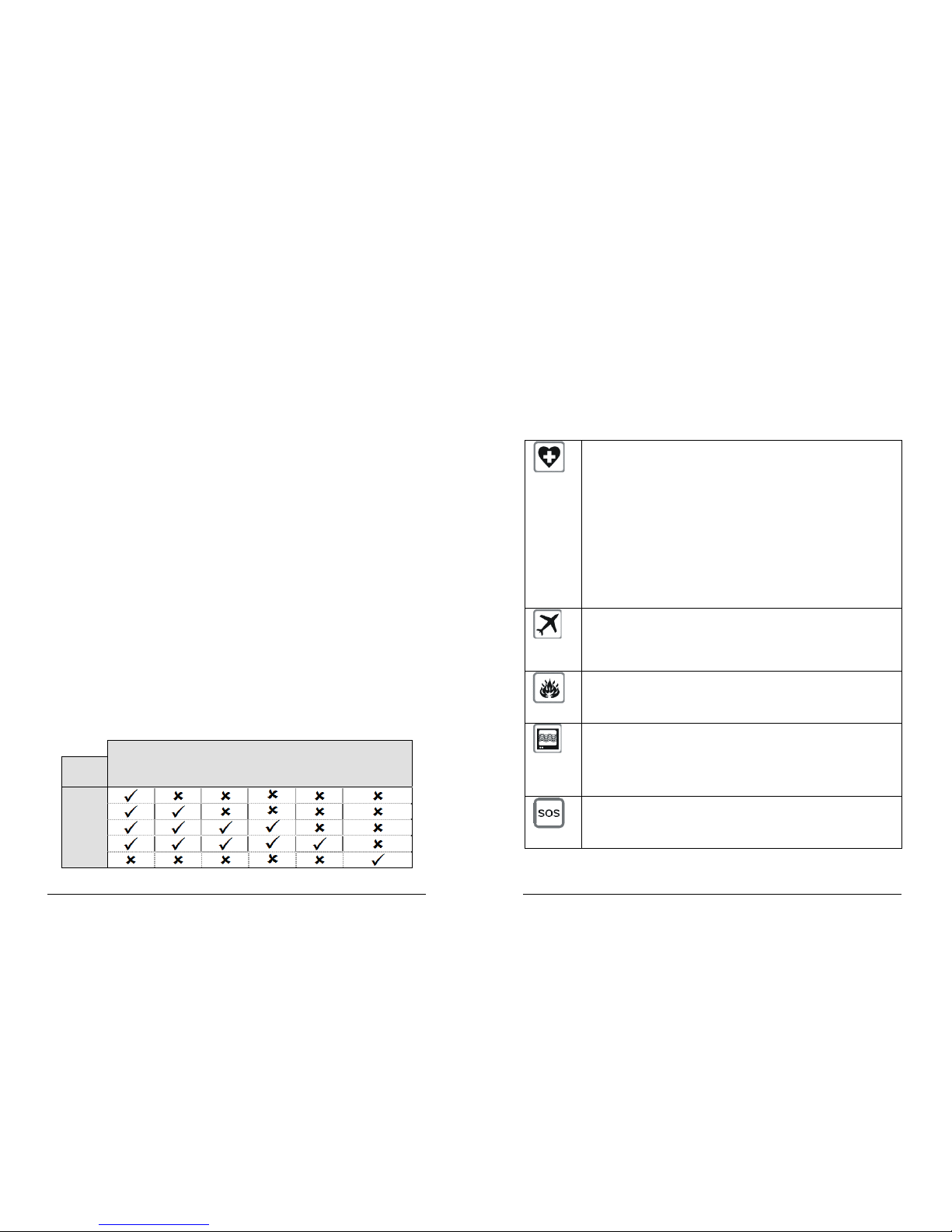
Wireless Networks
The wireless networks supported by the WR41 series routers fall into three categories:
• GSM networks (GPRS, EDGE)
• WCDMA networks (UMTS, HSDPA, HSUPA )
• CDMA450 networks (EVDO 1xRTT)
The type of network supported by each model is summarised in the table bel ow:
Network
Model GSM
GPRS
GSM
EDGE
WCDMA
UMTS
WCDMA
HSDPA
WCDMA
HSUPA
CDMA450
EVDO1xRTT
WR41-G
WR41-E
WR41-H
WR41-U
WR41-C
WR41 Series Installation Guide
3
Special notes on safety for wireless routers.
Digi International products are designed to the highest standards of safety and
international standards compliance for the markets in which they are sold. However, GSM
based products contain radio devices which require specific consideration. Please take
the time to read and understand the following guidance. Digi International assumes no
liability for an end user’s failure to comply with these precautions.
Wireless routers incorporate a wireless radio module. Users should
ensure that the antenna(s) is (are) positioned at least 1 metre away from
themselves and other persons in normal operation.
When in a hospital or other health care facility, observe the restrictions on
the use of mobile phones. Do not use the router in areas where
guidelines posted in sensitive areas instruct users to switch off mobile
phones. Medical equipment may be sensitive to RF energy.
The operation of cardiac pacemakers, other implanted medical
equipment and hearing aids can be affected by interference from cellular
terminals such as the wireless routers when placed close to the device. If
in doubt about potential danger, contact the physician or the
manufacturer of the device to verify that the equipment is properly
shielded. Pacemaker patients are advised to keep the wireless router
away from the pacemaker while it is on.
Wireless routers must NOT be operated on aircraft. The operation of
wireless appliances in an aircraft is forbidden to prevent interference with
communications systems. Failure to observe these instructions may lead
to the suspension or denial of cellular services to the offender, legal
action, or both.
As with any electrical equipment, you should not operate your wireless
router in the presence of flammable gases, fumes or potentially explosive
atmospheres. Radio devices should not be used anywhere that blasting
operations are taking place.
Wireless routers receive and transmit radio frequency energy while
switched on. Remember that interference can occur if it is used close to
TV sets, radios, computers or inadequately shielded equipment. Follow
any special regulations and always switch off your wireless router
wherever forbidden or when you suspect that it may cause interference
or danger.
SOS IMPORTANT! – Wireless routers operate using radio signals and
cellular networks cannot be guaranteed to connect in all possible
conditions. Therefore, you should never rely solely upon any wireless
device for life critical communications.
Page 3
WR41 Series Installation Guide
4
Preface
This guide describes the installation procedure for the WR41 range of routers. It is
intended to provide sufficient information for you to be able to connect the unit to your
terminal equipment and power supply. A complete reference guide to the software
features that are available on the product is available separately in PDF format which can
be downloaded from the Digi International website (www.digi.com
).
All models in the WR41 range feature:
♦ 1 x 10/100Base-T Ethernet port
♦ 1 x RS232 asynchronous serial port (RJ45 connector)
♦ 1 x USB 2.0 host port
♦ 2 x SIM / R-UIM sockets
♦ 1 x Wireless WAN interface (varies with model)
All models may also be purchased with one of a number of hardware options which are
listed in the section entitled “Optional Features” below.
Package Contents
When you receive the router carefully unpack it and check the contents. These should
include:
♦ WR41 system unit
♦ 5V DC 3A mains adapter (100V-230VAC, 50–60Hz, 0.6A max.)
♦ this Installation Guide
♦ 1 x 2M CAT5 STP (Shielded, Twisted Pair) LAN cable
♦ 1 x stub antenna (2 x with the –U and –C models)
If any item is missing or damaged, please contact your supplier. You should also make a
record of any damage that may have occurred during shipping and report it to the carrier.
If you have ordered one of the available hardware options the package will also contain
additional cables/antennas as appropriate.
WR41 Series Installation Guide
5
1 Introduction
WR41 series routers are compact IP routers that facilitate the transmission of data over
different types of “cellular” networks depending on the model.
The routers can be configured either by using commands entered at the serial port (much
like a modem), or via the built-in Web interface. We recommend that you use the Web
interface whenever possible.
In addition to many standard LAN and Internet protocols such as PPP, the WR41 series
products provide a combination of powerful but easy to use configuration, management
and diagnostic tools. This makes them simple and cost-effective solutions for migrating
existing terminal or telemetry equipment, which use wired networks (PSTN, ISDN, etc.), to
wireless operation.
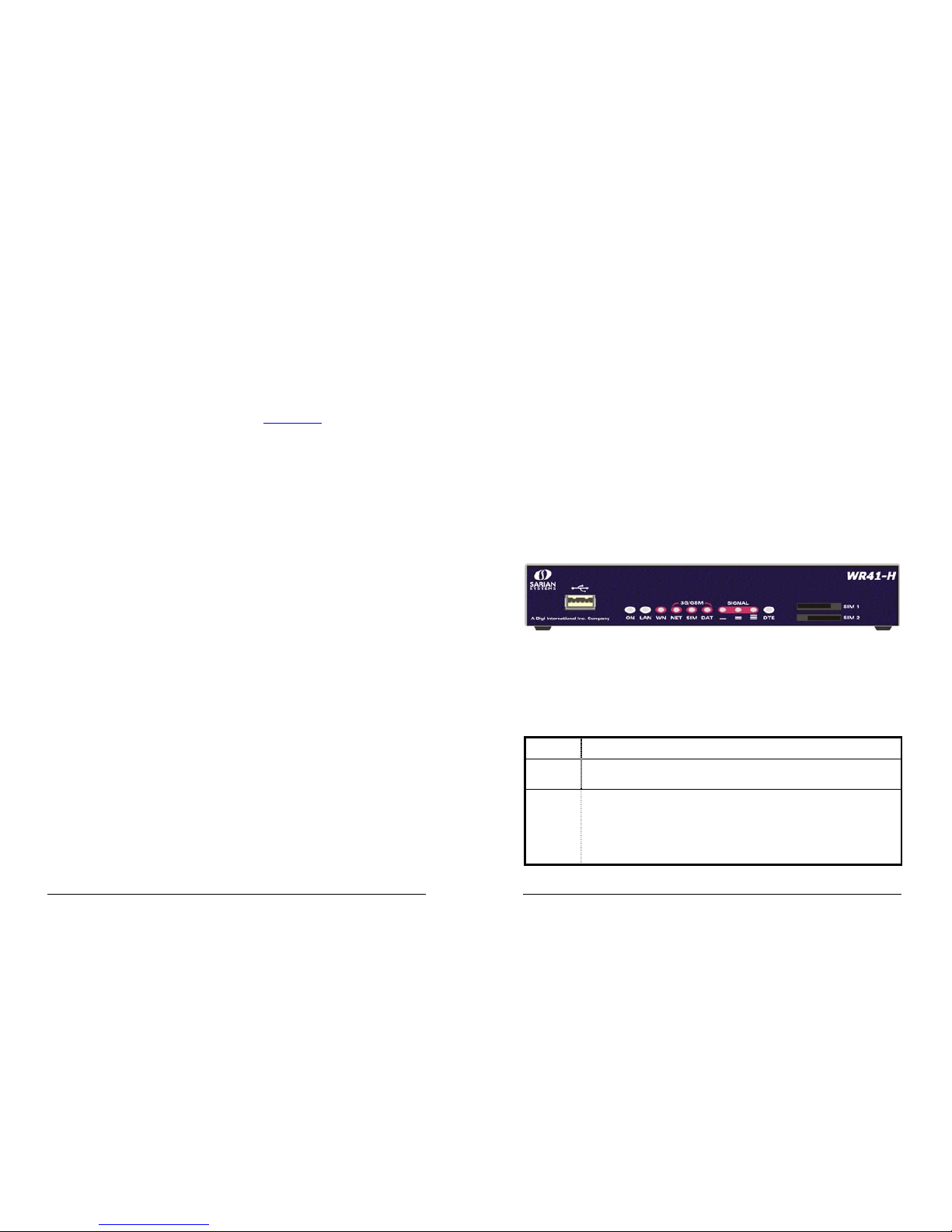
1.1 Front Panel Features
The front panel of the unit incorporates the USB host connector, 10 LED indicators and
the two SIM / R-UIM card-holders as shown in the following illustration of the WR41-H:
USB Host Connector
The USB host connector may be used to connect compatible USB 2.0 client devices such
as memory sticks, serial adapters, etc. Note that the total current available to power USB
devices is 0.5A.
Status Indicators
The status indicators operate as follows:
ON
Illuminates steady when power is applied.
LAN
Illuminates steady when there is a network connection to the LAN port
and flashes when data is transmitted or received.
WN
The indicator labelled WN (Wireless Network) flashes to show which
network mode the router is operating in as follows:
Off – no service
1 blink – GPRS mode
2 blinks – EDGE mode
Page 4

WR41 Series Installation Guide
6
3 blinks – UMTS mode
4 blinks – HSDPA mode
5 blinks – HSUPA mode
On steady – CDMA mode
NET
Illuminates steady when a wireless data connection has been
established.
SIM
Illuminates steady when a valid SIM card is installed in the unit.
DAT
Flashes to indicate that data is being transferred over the wireless
network.
SIGNAL
For the WR41-G, -E, -H and –U models, the three indicators labelled
SIGNAL illuminate to indicate the GSM signal strength as follows:
None illuminated < -113 dBm (effectively no signal)
1 LED illuminated >= -112 dBm and <= -87 dBm (weak)
2 LED’s illuminated >= -86 dBm and <= -71 dBm (medium)
3 LED’s illuminated >= -70 dBm and <= -51 dBm (strong)
For the WR41-C the signal strengths are as follows:
None illuminated < -116 dBm (effectively no signal)
1 LED illuminated >= -115 dBm and <= -104 dBm (weak)
2 LED’s illuminated >= -103 dBm and <= -94 dBm (medium)
3 LED’s illuminated >= -93 dBm and <= -83 dBm (strong)
DTE
Illuminates steady if a terminal is connected to the ASY0 serial port and
the DTR signal is on. Flashes when data is transmitted or received.
SIM / R-UIM Sockets
On the WR41-G, E, H and U, the two sockets at the right side of the front panel labelled
SIM 1 and SIM 2 are for use with the Subscriber Identification Module(s) (SIMs) that you
will receive from your service provider(s).
On the WR41-C, the same sockets are present but are labelled R-UIM (Removable User
Identification Module) because this is a more commonly used term in the CDMA network
arena.
SIMs and R-UIMs are essentially the same in function and for the remainder of this guide
are referred to simply as SIMs or SIM cards.
Details of how to insert SIM cards correctly are given in section 2 below.
WR41 Series Installation Guide
7
1.2 Rear Panel Features
The rear panel of the unit incorporates a number of connectors as described as shown
below (model shown with no options fitted):
5V DC
This jack socket is used to connect the unit to the power supply
using 5V DC mains adapter.
ASY 0
This RJ45 socket provides an asynchronous RS232 serial port
which may be used to connect the router to a compatible serial
device. The unit is supplied with a suitable 2 metre serial cable.
To comply with EMC requirements it should not be used with a
longer cable.
ANT. (MAIN)
This SMA connector is used to fit the wireless antenna. The
WR41-G, E and H models are supplied with a single stub antenna
which should be fitted to this connector.
The WR41-U and C models both support “diversity” antenna
capability to improve performance and are there supplied with two
stub antennas. One of these should be fitted to this connector and
the other to the ANT. (AUX) connector.
Note: Small stub antennas are provided as standard but a range
of suitable alternative for use in different applications may be
purchased separately.
ANT. (AUX.)
This SMA connector is used on the WR41-U and C models to fit
the second antenna supplied with the unit. On models that do not
support diversity antennas this connector will not be present.
LAN
The socket labelled LAN is used to connect the unit to a
10/100Base-T LAN using the 2-metre STP (Shielded Twisted
Pair) cable supplied or a suitable alternative. This port is autosensing for speed and wiring (straight-through or cross-over). To
comply with EMC requirements it should not be used with nonSTP cable.
Page 5

WR41 Series Installation Guide
8
Reset button
This is located on the underside of the unit near the front (just behind the DTE LED), and
can be accessed through a 2.5mm hole using pencil tip or similar implement. Holding the
reset button down gently for 5 seconds when the unit is powered up and operational (i.e.
has finished booting), will cause the factory settings to be loaded into flash before and
then re-boot. During this time you will see a pattern of alternating LEDs flashing followed
by the normal boot sequence. Do not remove power from the unit during this operation, as
corruption of the flash memory may occu r.
1.3 Optional features.
WR41 series routers are available with a variety of hardware options. At present these
are:
1 x ASY
Provides an additional asynchronous serial port using a 25-way D
connector
3 x ASY
Provides three additional asynchronous serial ports using RJ45
connectors.
1 x SYN
Provides an X.21/RS422/RS232 synchronous serial port using a
25-way D connector.
1 x GPS
Provides GPS geo-location capability.
1 x ISDN BRI
Provides an ISDN Basic Rate Interface (BRI) via an RJ45 socket.
This can be configured either as a TE (terminal endpoint) or as
NT-1 (network termination). The option also includes an additional
asynchronous serial port via a second RJ45 socket.
Only one of the above options can be fitted and will occupy the area of the rear panel
normally covered with the blanking plate. For example, if the GPS option is fitted, the rear
panel will appear as shown below:
WR41 Series Installation Guide
9
2 Installation
Note: You will not be able to use the router for remote communication until you have
subscribed to a suitable wireless network service.
WR41 series products are designed for indoor use (office or home). They should be
positioned on a smooth, level surface making sure that there is adequate ventilation. Do
not expose them to extremes of heat or cold, strong magnetic fields or liquids.
It is important to remember that these products are wireless devices just like a mobile
phone, so they will only operate reliably if there is a good quality signal from the network.
For many applications the stub antenna provided will be suitable but in some
circumstances it may be necessary to use a window-mounted or magnetically mounted
antenna with an extended cable to allow the antenna itself to be positioned to provide the
best possible signal reception. Digi International can supply a range of suitable antennas.
Important: If you are going to be using the Sar/OS Connection Wizard to configure the
unit’s Ethernet port and also connect it to your GSM/3G network, skip this section and
proceed to Configuration.
Step 1 - Installing the SIM card(s)
The router incorporates two separate SIM card holders so that if your application
demands it, you may install SIMs for two different networks. This means that one wireless
service may be used as a back-up service in the event that the primary service fails in
some way. By default, SIM 1 is the default SIM used for access to the primary network
and SIM 2 is used for the back-up network.
Notes:
1. SIM 1 and SIM 2 can NOT be used to access two networks simultaneously.
2. When using the WR41-C, not all networks require/support the use of Removable User
Identity Modules (R-UIM’s). If your service provider does not support R-UIMS, your router
may have been “provisioned” for use on your chosen network before you receive it and
this stage of the installation procedure will not be required. If your router has NOT been
provisioned, you will need to contact your service provider to obtain an “IMSI” and “NAI” in
order to provision the unit manually.
The SIM card(s) should be inserted into SIM cardholders on the right of the front panel as
illustrated below.
Page 6

WR41 Series Installation Guide
10
In both cases, the end of the SIM card with the chamfered corner should be inserted first.
For SIM 1 the contacts should be face down. For SIM 2 the contacts should be face up.
Step 2 – Fitting the wireless antenna(s)
The router is supplied with a “stub” antenna suitable for with the model you have ordered.
Alternatively you may have ordered a different type of antenna separately. In either case
this should be screwed onto the SMA connector labelled ANT.(MAIN) on the rear panel.
If you have a WR41-U or WR41-C, the unit will come with two antennas. When both of
these are fitted the operation over the wireless network may be improved, especially in
areas of low signal strength. This is called “diversity” mode. The second antenna should
be screwed onto the SMA connector labelled ANT.(AUX.) on the rear panel.
Note: If you use antennas other than the stub antennas supplied as standard (e.g. two
wall-mount antennas), the separation between the two should be no less than the
separation between the two associated connectors on the rear panel of the unit.
Step 3 – Connecting the LAN cable
Plug one end of one of the supplied 2 metre CAT5 STP cable into the RJ45 socket
labelled LAN 0. Plug the other end into the LAN socket on your PC or notebook.
Step 4 – Connecting the serial cable
For connection to a serial terminal device, an RJ45 to 9-way D-type adapter is required
and can be purchased separately. Connect the RJ45 plug on the adapter into the socket
labelled ASY 0 on the rear panel of the router. A suitable serial cable can then be used to
connect the router to the serial port on your terminal.
Step 5 – Connecting the power supply
Plug the jack plug on the mains adapter into the socket labelled 5V DC. When power is
first applied, the ON indicator will illuminate and the unit will initiate a series of diagnostic
self-tests. During this process one or more of the other indicators, will flash to show that
the unit is busy. When the flashing stops, the unit is ready to use.
The unit is now ready to be configured.
WR41 Series Installation Guide
11
3 Configuration
Once the router has been installed and powered up, you must now configure it to
communicate with your network and the Internet. The easiest way to do this is to use the
Sar/OS Connection Wizard, available from the Digi website.. The Sar/OS Connection
Wizard will take you step-by-step through the process of configuring the router.
You can choose to just configure the unit’s Ethernet port (so that you can connect to it
over your LAN in order to configure it fully), or you can use the wizard to configure the
unit’s Ethernet port, and at the same time connect it to your wireless network.
Using the wizard means that you will not have to change the IP address of your PC.
Rather, you will be able to change the IP address of the router to match the subnet your
PC is already on.
Note: The default IP address for the LAN 0 port is 192.168.0.99, with a Class C subnet
(255.255.255.0). Setting your PC’s IP address to one on the same subnet (192.168.0.*)
will enable you to connect to the unit’s Web interface. You will then be able to configure
the unit manually.
Step 1 – Install the Connection Wizard
Download the connection wizard from the Digi website and install the software on your
PC.
Step 2 – Run the Wizard
Once the wizard has been installed on your PC, run it from the Windows Start menu.
Step 3 – Decide which configuration method to use
Choose to either configure the unit’s Ethernet port only, or configure the unit’s Ethernet
port and at the same time connect it to your wireless network. For the WR41-C you should
choose to configure the unit’s Ethernet port only.
If you choose to configure the unit’s Ethernet port only, you must have completed all the
installation steps listed in the previous section.
Step 4 – Configure the unit
Follow the on-screen instructions to configure the unit according to the method you have
chosen. Once complete you will be able to browse to the unit and configure it using your
web browser.
Page 7

WR41 Series Installation Guide
12
4 General Specifications
Model numbers WR41-G, WR41-E, WR41-H, WR41-U, WR41-C
Power supply 5V DC / 3A
Dimensions / Weight W172 x D110 x H32 mm, 0.53 Kg
Operating temp. range -20 to +50 degree Celsius
WR41-G
GSM/GPRS modem
Tri-band GSM 900/1800/1900 MHz GPRS multi-slot class 10 (max
85.6 kbps downlink), mobile station class B, coding schemes CS 1-4
WR41-E
GSM/GPRS/EDGE modem
Quad-band GSM 850/900/1800/1900 MHz EDGE (E-GPRS) multi-slot
class 10 (max 236.8 kbps downlink), mobile station class B,
modulation and coding scheme MCS1-9
GPRS multi-slot class 10, mobile station class B, PBCCH support,
coding schemes CS 1-4
WR41-H
GSM/GPRS/EDGE/
UMTS/HSDPA modem
HSDPA 1.8 Categories 1-4, 11 and 12
HSDPA 3.6 Categories 5 and 6
UMTS: 384 Kbps downlink, 384 Kbps uplink
MO 0201: 850/1900/2100 (Rx diversity) MHz
Quad-band GSM 850/900/1800/1900 MHz EDGE (E-GPRS) multi-slot
class 12 (max 236.8 kbps downlink), mobile station class B,
modulation and coding scheme MCS1-9
GPRS multi-slot class 12, mobile station class B, PBCCH support,
coding schemes CS 1-4
WR41-U
GSM/GPRS/EDGE/
UMTS/HSDPA/HSUPA
modem
HSUPA mode: 2 Mbps Category 5
HSDPA 1.8: Categories 1-4, 11 and 12
HSDPA 3.6: Categories 5 and 6
HSDPA 7.2: Categories 7 and 8
UMTS: 384 Kbps downlink, 384 Kbps uplink
MO 0301: 850/1900/2100 (Rx diversity) MHz
MO 0302: 850 (Rx Diversity) / 1900 (Rx Diversity) / 2100 MHz
Equalization and Rx Diversity at the same time Quad-band GSM
850/900/1800/1900 MHz EDGE (E-GPRS) multi-slot class 12 (max
236.8 kbps downlink), mobile station class B, modulation and coding
scheme MCS1-9
GPRS multi-slot class 12, mobile station class B, PBCCH support,
coding schemes CS 1-4
USB ports One USB 2.0 Full-speed Host(12 Mbits/second maximum throughput)
Ethernet interface 10/100Base-T auto-sensing, auto-MDI/MDX (RJ45)
Serial interface Asynchronous RS232 compatible (RJ45)
WR41 Series Installation Guide
13
5 Declaration of Conformity
Declaration of Conformity for R&TTE Directive
We: Digi International.
Beacon House,
Riverside Business Park,
Ilkley, West Yorkshire, LS29 8JZ
ENGLAND
declare under our sole responsibility that WR41- series products with part numbers 50001657-xx (where xx can be any number from 00 to 99), conform to the relevant harmonised
standards:
WR41-G, E, H & U models only:
EN60950-1 A11: 2004 (Health & Safety)
EN301 489-7: v1.2.1 (EMC)
EN301511: v9.0.2 (RF spectrum efficiency)
WR41-C only:
EN60950-1 A11: 2004 (Health & Safety)
EN301 489-25: v2.3.2 (2005-7) (EMC)
EN301 526: v1.1.1 (RF spectrum efficiency)
following the provisions of Council Directive 1999/5/EC on radio equipment and
telecommunications terminal equipment and the mutual recognition of their conformity.
Name: D. Ellison
Position: Director
Signature
:
Date: 31
st
March 2009
on behalf of Digi International.
 Loading...