

Page 1

ConnectPort™ X5 Family
User’s Guide
ConnectPort X5 R
ConnectPort X5 Fleet
ConnectPort X5 K
90001100_C
Page 2

©Digi International Inc. 2010. All Rights Reserved.
The Digi logo, Digi Connect, iDigi, ConnectPort, Digi SureLink, Digi Dialserv are trademarks or
registered trademarks of Digi International, Inc.
All other trademarks mentioned in this document are the property of their respective owners.
Information in this document is subject to change without notice and does not represent a
commitment on the part of Digi International.
Digi provides this document “as is,” without warranty of any kind, either expressed or implied,
including, but not limited to, the implied warranties of fitness or merchantability for a particular
purpose. Digi may make improvements and/or changes in this manual or in the product(s) and/or
the program(s) described in this manual at any time.
This product could include technical inaccuracies or typographical errors. Changes are periodically
made to the information herein; these changes may be incorporated in new editions of the
publication.
2
Page 3

Contents
Contents........................................................................................................................................................................................3
About this guide...........................................................................................................................................................................7
Purpose................................................................................................................................................................................7
Audience..............................................................................................................................................................................7
Scope...................................................................................................................................................................................7
Where to find more information..........................................................................................................................................7
Digi contact information .....................................................................................................................................................8
Chapter 1: Introduction............................................................................................................................................................9
Important Safety Information................................................ .................................. ............................................................9
ConnectPort X5 Family products................................................................ ......................................................................10
Wireless carrier certifications............................................................................................................................................11
Features .............................................................................................................................................................................12
User interfaces.........................................................................................................................................................12
Quick reference for configuring features ................................................................................................................13
Hardware features ...................................................................................................................................................19
Network interface features ......................................................................................................................................19
Configurable network services................................................................................................................................19
IP protocol support..................................................................................................................................................20
Mobile/Cellular features and protocol support........................................................................................................24
RealPort software....................................................................................................................................................25
Alarms.....................................................................................................................................................................25
Modem emulation ...................................................................................................................................................25
Security features......................................................................................................................................................26
Configuration management............................................................... ......................................................................27
Customization capabilities ........................................................... ................................. ..........................................27
Supported connections and data paths in Digi devices .....................................................................................................28
Interfaces for configuring, monitoring, and administering Digi devices..........................................................................31
Configuration capabilities ................................................... ....................................................................................31
Configuration interfaces.......................................................................................................
Monitoring capabilities and interfaces....................................................................................................................38
Device administration ........................................ .................................. ...................................................................39
...................................31
3
Page 4

Chapter 2: Hardware installation..........................................................................................................................................40
Cable harness guidelines...................................................................................................................................................41
ConnectPort X5 main connector .............................................................................................................................41
Available interfaces on the ConnectPort X5 main connector.................................................................................44
Mounting the ConnectPort X5 to a vehicle.......................................................................................................................46
ConnectPort X5 R .......................... .................................. .................................. .....................................................46
ConnectPort X5 Fleet............................................................................................... ...............................................47
Antennas............................................................................................................................................................................48
ConnectPort X5 R .......................... .................................. .................................. .....................................................48
ConnectPort X5 Fleet............................................................................................... ...............................................51
ConnectPort X5 K development kit ............................. .................................. ... ................................................................52
Chapter 3: Configure Digi devices.........................................................................................................................................53
Default IP address and methods for assigning an IP address............................................................................................54
Configure an IP address using DHCP.....................................................................................................................54
Configure an IP address using Auto-IP...................................................................................................................54
Test the IP address configuration.......................... .................................. ................................................................54
Configuration through the iDigi Platform.........................................................................................................................55
Create an Account on iDigi.com........................... .................................. .................................. .. ............................55
Add the Digi device to the idigi.com Device List...................................................................................................56
iDigi Platform views for configuring and managing Digi devices .........................................................................58
Configuration through the web interface...........................................................................................................................63
Open the web interface.............................................................. ..............................................................................63
Organization of the web interface...........................................................................................................................65
Change the IP address from the web interface, as needed ......................................................................................67
Network configuration settings ...............................................................................................................................68
Mobile (cellular) settings ......................................................................................................................................112
XBee network settings ..........................................................................................................................................135
Serial port settings.................................................................................................................................................145
Alarms...................................................................................................................................................................154
System settings......................................................................................................................................................158
Remote management settings................................................................................................................................164
Security settings ....................................................................................................................................................169
Position (GPS support).........................................................................................................
.................................172
Applications ..........................................................................................................................................................174
Configuration through the command line .......................................................................................................................178
Access the command line...................................................................................... ................................................178
Verify device support of commands .....................................................................................................................178
Configuration through Simple Network Management Protocol (SNMP).......................................................................181
Batch capabilities for configuring multiple devices........................................................................................................181
4
Page 5

Chapter 4: Monitor and manage Digi devices....................................................................................................................182
Monitoring capabilities from the iDigi Platform.............................................................................................................183
Monitoring capabilities in the web interface...................................................................................................................184
Display system information ..................................................................................................................................184
Manage connections and services.........................................................................................................................201
Monitoring capabilities from the command line .............................................................................................................204
Commands for displaying device information and statistics ................................................................................204
Commands for managing connections and sessions .............................................................................................206
Commands for managing XBee networks and nodes ...........................................................................................207
Monitoring Capabilities from SNMP..............................................................................................................................208
Chapter 5: Digi device administration ................................................................................................................................209
Administration from the web interface ...........................................................................................................................209
File management...................................................................................................................................................210
X.509 Certificate/Key Management .....................................................................................................................211
Backup/restore device configurations...................................................................................................................214
Update firmware and Boot/POST Code................................................................................................................214
Restore a device configuration to factory defaults................................................................................................215
Display system information ..................................................................................................................................216
Reboot the Digi device..........................................................................................................................................216
Enable/disable access to network services............................................................................................................216
Administration from the command-line interface...........................................................................................................217
Chapter 6: Programming .....................................................................................................................................................218
Programming tools and resources .................................................................. .................................................................219
The Digi API for receiving and sending vehicle bus date.....................................................................................219
Vehicle bus protocol specifications.......................................................................................................................219
Digi Developer Community Wiki.........................................................................................................................220
Digi Python Custom Development Environment page.........................................................................................220
Digi Python Programming Guide..........................................................................................................................220
Python Support Forum on digi.com......................................................................................................................220
ConnectPort X5 programming examples and information ...................................................................................220
iDigi Dia................................................................................................................................................................221
iDigi Platform........................................................................................................................................................221
The Digi API for automotive/heavy industry protocols..................................................................................................222
Vehicle bus protocol specifications.......................................................................................................................222
Power consumption and management ............................................................................................................................236
External power control device...............................................................................................................................236
Sleep mode and waking.........................................................................................................................................236
5
Page 6

Chapter 7: Specifications and certifications.......................................................................................................................237
Hardware specifications..................................................................................................................................................238
ConnectPort X5 R and ConnectPort X5 K specifications.................................. ...................................................238
ConnectPort X5 Fleet specifications.....................................................................................................................239
Wireless networking features....................................... ... .................................. ... ...........................................................240
Regulatory information and certifications.......................................................................................................................242
RF exposure statement ..........................................................................................................................................242
FCC certifications and regulatory information (USA only)..................................................................................242
Industry Canada (IC) certifications.......................................................................................................................243
Safety statements...................................................................................................................................................244
.International EMC (Electromagnetic Emissions/Immunity/Safety) standards ....................................................245
Environmental requirements for ConnectPort X5 Family products......................................................................246
Chapter 8: Troubleshooting.................................................................................................................................................247
Troubleshooting Resources.............................................................................................................................................247
System status LEDs.........................................................................................................................................................248
ConnectPort X5 R LEDs........................................................... .................................. ..........................................248
Glossary....................................................................................................................................................................................251
6
Page 7

Purpose
Audience
Scope
About this guide
This guide describes and shows how to install, provision, configure, monitor, and administer Digi
devices.
This guide is intended for those responsible for setting up Digi devices. It assumes some
familiarity with networking concepts and protocols.
This guide focuses on configuration, monitoring, and administration of Digi devices. It does not
cover hardware details beyond a certain level, application development, or customization of Digi
devices.
Where to find more information
In addition to this guide, find additional product and feature information in the these documents:
Online help and tutorials in the web interface for the Digi device
Quick Start Guides
RealPort
Cellular 101 Tut orial
Digi Connect Family Customization and Integration Guide
iDigi tutorials and user’s guides
Release Notes
Cabling Guides
Product information available on the Digi website, www.digi.com, and Digi's support
site at www.digi.com/support, including, Support Forums, Knowledge Base, Data
sheets/product briefs, application/solution guid es, and carrie r-specific documents
®
Installation Guide
Python developer Wiki
7
Page 8

Digi contact information
For more information about Digi products, or for customer service and technical support, contact
Digi International.
To Contact Digi International
Use:
by:
Mail Digi International
11001 Bren Road East
Minnetonka, MN 55343
U.S.A.
World Wide Web: http://www.digi.com/support/
email http://www.digi.com/contactus/email.jsp/
Telephone (U.S.) (952) 912-3444 or (877) 912-3444
Telephone (other locations) +1 (952) 912-3444 or (877) 912-3444
8
Page 9

Introduction
CHAPTER 1
This chapter introduces Digi devices and their product families, types of connections and data
paths in which Digi devices can be used, and the interface options available for configuring,
monitoring, and administering Digi devices.
Important Safety Information
To avoid contact with electrical current:
Introduction
Never install electrical wiring during an electrical storm.
Never install an Ethernet connection in wet locations unless that connector is
specifically designed for wet locations.
Use caution when installing or modifying lines.
Use a screwdriver and other tools with insulated handles .
Wear safety glasses or goggles.
Do not place Ethernet wiring or connections in any conduit, outlet or junction box
containing electrical wiring.
Installation of inside wire may bring you close to electrical wire, conduit, terminals and
other electrical facilities. Extreme caution must be used to avoid electrical shock from
such facilities. Avoid contact with all such facilities.
Ethernet wiring must be at least 6 feet from bare power wiring or lightning rods and
associated wires, and at least 6 inches from other wire (antenna wires, doorbell wires,
wires from transformers to neon signs), steam or hot water pipes, and heating ducts.
Do not place an Ethernet connection where it would allow a person to use an Ethernet
device while in a bathtub, shower, swimming pool, or similar hazardous location.
Protectors and grounding wire placed by the service provider must not be connected to,
removed, or modified by the customer.
Do not touch uninsulated Ethernet wiring if lightning is likely!
External Wiring: Any external communications wiring installed needs to be constructed
to all relevant electrical codes. In the United States this is the National Electrical Code
Article 800. Contact a licensed electrician for details.
9
Page 10

ConnectPort X5 Family products
The ConnectPort X5 Family offers compact, ruggedized telematics gateways for cost-effective
fleet management and asset tracking solutions. These gateways provide remote connectivity to
mobile assets to monitor operating health, performance, location and driver/operator behavior, as
well as to enable automated event reporting. They aggregate wireless vehicle Personal Area
Network (VP AN) traf fic, such as ZigBee and 80 2.15.4 point-to-multi point, for IP connectiv ity over
a secure cellular, Wi-Fi, or satellite connection in harsh environments.
Gateways in the ConnectPort X5 family include the ConnectPo rt X5 R and ConnectPort X5 K, and
ConnectPort X5 Fleet. The ConnectPort X5 K was designed as a development kit to be used for
testing and evaluation prior to de plo yme nt of the ConnectPort X5 R or ConnectPort X5 Fleet. The
ConnectPort X5 K comes with a development cable, antennas, and, for GSM versions, has an
opening in the enclosure to allow users to insert their own SIM card. As such, the
ConnectPort X5 K should be used for testing and evaluation only. Customers will be responsible
for procuring antennas and cabling for their specific ConnectPort X5 R and ConnectPort X5 Fleet
installations.These gateways support vehicle personal area networks with Digi’s industry-leading
XBee radio technology. Vehicle personal area networks (VPANs) allow users to deploy low-power
sensor networks within and around the vehicle or mobile asset to monitor additional asset points,
for example, tires, reefer units, door latch, temperature sensors, cargo sensors, RFID readers, etc.
Introduction
The ConnectPort X5 family provides flexible wide-area networking connectivity supporting
cellular, Wi-Fi, and satellite communications. Cellular connectivity provides instant, always-on
communications, while Wi-Fi provides a cost-effective way to transfer large files, firmware, or
logs across low-cost private Wi-Fi networks. The ConnectPort X5 Wi-Fi feature can also be used
to network in-vehicle or near-vehicle Wi-Fi-enabled devices, such as vehicle displays and
handheld mobile devices.
Features and benefits of the ConnectPort X5 gateway family include:
Factory-sealed IP67 enclosure, ensuring protectio n from dust and total wat er immersion
to 1 meter
Programmable for application developmen t through the Pyt hon programming la nguage,
iDigi device integration applications (Dia) and the iDigi services platform
J1708 protocol support, offering serial connectivity to a large installed base of heavy
duty vehicle fleets
Controller Area Network (CAN) interface support for connection to J1939 or
proprietary vehicle bus
Advanced power management, including sensitivity to ignition status
Location tracking and geofencing with on-board GPS
Global cellular coverage over GSM/GPRS or CDMA networks
Optional satellite on the ConnectPort X5 Fleet
Automated event reporting: the gateway can continuously transmit vehicle status at
user-defined intervals
iDigi Management Services for management and monitoring
10
Page 11

Wireless carrier certifications
Digi devices are being certified around the world with major carriers supporting these
technologies. For a current list of carrier certifi cations for your Digi product, go to dig i.com and go
the product pages for your product. Click the Specs tab of the product pages. Carrier certifications
are listed under Mobile Certifications or Carrier Certifications.
Introduction
11
Page 12

Features
User interfaces
Introduction
This is an overview of key features in Digi devices. Software features are covered in more detail in
the next three chapters. Hardware specifications and are covered in Chapter 7, "Specifications and
certifications"
There are several user interfaces for configuring and monitoring Digi devi ces, in clu di ng the
following.
The iDigi Platform
A web-based interface for configuring, monitoring, and administering Digi devices.
Plugging the ConnectPort X5 device into a switch or network to which a laptop
computer is connected allows direct access to the web interface for configuration.
A command-line interface available via local serial port, telnet or SSH.
Simple Network Management Protocol (SNMP).
12
Page 13

Quick reference for configuring features
This guide primarily focuses on configuring, monitoring, and administ erin g D igi device s from the
web interface. This table provides a quick reference for configuring features and performing
device tasks, and where to find the features and settings in the web interface and this guide. Click
the page number in the Page column to jump to instructions on configuring or using the feature.
Some features are configurable from the command line interface only. In those cases, the
commands that configure the feature are noted. The command descriptions are in the Digi Conn ect
Family Command Reference.
Feature/task Path to feature in the web interface See page
Administration/Configuration management:
Introduction
File management: uploading and
downloading files, such as applet
files, and custom splash screens.
Python program file
management.
Backup/restore a configuration
from a TFTP server on the
network
Update firmware
Reset configuration to factory
defaults
System information, including
device identifiers and statistics
Reboot the Digi device
Certificate and key management,
including X.509, VPN, SSL,
SSH
Administration > File Management
210
See also the Digi Connect Family Customization and Integration Guide for
information on uploading and downloading files used to customized a Digi
device’s look-and-feel.
Applications > Python 174
Administration > Backup/Restore 214
Administration > Update Firmware 214
Administration > Factory Default Settings 215
Administration > System Information 216
Administration > Reboot 216
Administration > X.509 Certificate and Key Management 211
Alarms Configuration > Alarms 154
Autoconnection: automatically
connect a user to a server or network
Configuration > Serial Ports > port > Profile Settings > TCP Sockets >
Automatically establish TCP connections
147
device
13
Page 14

Feature/task Path to feature in the web interface See page
Connection management:
Introduction
Manage serial port connections
Manage Virtual Private Network
Management > Serial Ports 201
Management > Connections > Virtual Private Network (VPN) Settings 201
(VPN) connections
Manage active system
Management > Connections > Active System Connections 201
connections
Manage network services
Management > Network Services
202
(Currently only DHCP server settings managed from here)
Domain Name System (DNS):
DNS Client
Dynamic DNS (DDNS) update
Dynamic Host Configuration Protocol
(DHCP) server
Configuration > Network > Advanced Network Settings 107
Configuration > Network > Dynamic DNS Update Settings 82
To configure a DHCP server:
75
Configuration > Network > DHCP Server Settings
To start and stop and show status of a DHCP server:
Management > Network Services > DHCP Server Management
Ethernet settings Configuration > Network > Advanced Network Settings 107
Event logging for the Digi device Management > Event Logging 201
Help on configuring features Help button on each page.
Host name for a device Configuration > Network > Advanced Network Settings > Host Name 107
IP address settings Configuration > Network > IP Settings
54, 70, 75, 107
Configuration > Network > Advanced Settings
IP filtering / access control Configuration > Network > IP Filtering Settings 85
IP forwarding: Network Address
Configuration > Network > IP Forwarding Settings 86
Translation (NAT) and port
forwarding configuration/static routes
IP pass-through Configuration > Network > IP Pa ss-through 94
14
Page 15

Feature/task Path to feature in the web interface See page
Mobile (cellular) settings:
Introduction
Provisioning the cellular
modules
Configuration > Mobile
For Digi Cellular product that have a cellular module, provisioning must be
performed once.
To launch a wizard for provisioning the module, go to
Configuration > Mobile. Under Mobile Service Provider Settings, click
the Provision Device button.
Provisioning can also be performed from the command line:
To provision the CDMA module: provision
To display existing provisioning parameters: displayprovisioning
Mobile service provider and
connection settings
SureLink™ settings
Short Message Service (SMS)
Configuration > Mobile
Settings displayed vary by mobile service provider.
Configuration > Mobile > SureLink Settings.120
Configuration > Mobile > Short Message Service (S MS) Settings 125
settings
Modem emulation Configuration > Serial Ports > Port Profile Settings >
Modem Emulation
See the Connect Family Command Reference for modem emulation
commands.
114
113, 120
149
Port profiles: sets of preconfigured
Configuration > Serial Ports > Port Profile Settings 145
serial-port settings for a particular
connection and use scenario
Python support: loading and running
custom programs authored in the
Python programming language.
RealPort (COM port redirection)
configuration
Applications > Python
For more information on writing and running Python programs, see the
Digi Python Programming Guide.
Configuration > Serial Ports > port > Port Pr ofile Settings > RealPort
See also the RealPort Installation Guide.
174
146
Remote device management Configuration > Remote Management 164
Reverting configuration settings Administration > Factory Default Settings 215
15
Page 16

Feature/task Path to feature in the web interface See page
Security/access control features:
Introduction
Control access to inbound ports
Secure Shell Server (SSH)
Establish/change user name for a
user
Issue a new/cha nged password to
a user
Serial port configuration:
Basic serial port settings
Advanced serial port settings
Port profiles: associate a serial
port with a set of preconfigured
port settings for a specific use
RCI over serial mode
Configuration > Serial Ports > port > Port Profile Settings >
145
TCP Sockets or UDP Sockets or Custom port profile
Network > Network Services > Enable Secure Shell Server (SSH) 80
Configuration > Security 169
Configuration > Security 169
Configuration > Serial Ports > Basic Serial Settings 150
Configuration > Serial Ports > Advanced Serial Settings 151
Configuration > Serial Ports > Port Profile Settings 145
Configuration > Serial Ports > Advanced Serial Settings 151
RTS Toggle
TCP serial connections
UDP serial characteristics
Configuration > Serial Ports > Advanced Serial Settings 151
Configuration > Serial Ports > port > Port Profile Settings >
147
TCP Sockets port profile
Configuration > Serial Ports > port > Port Profile Settings > UDP
148
Sockets port profile
16
Page 17

Feature/task Path to feature in the web interface See page
Simple Network Management Protocol (SNMP):
Introduction
Configure SNMP through the
web interface
Enable/disable SNMP service
Enable/disable SNMP alarm
traps
Use SNMP as primary
configuration interface
Configuration > System > Simple Network Management Protocol
(SNMP) Settings
Configuration > Network > Network Services 79
Configuration > Alarms > alarm > Send SNMP trap to following
destination when alarm occurs
Basic network and serial settings configurable through standard and Digispecific Management Information Blocks (MIBs).
161
156, 157
37181
More advanced settings must be set through the web or command-line user
interfaces, and sending alarms as SNMP traps must be configured through
the web interface, on the pages listed above.
System information: assign system-
Configuration > System > Device Identity Settings 158
identifying information to a device
Socket Tunnel Settings Configuration > Network > Socket Tunnel Settings 93
Statistics for Digi devices Administration > System Information 184
Status of Digi devices Management > Serial Ports, Connections, Network Services 201
VPN (Virtual Private Network) To configure VPN:
94
Configuration > Network > Virtual Private Network (VPN) Settings
To manage VPN:
Management > Connections > Virtual Private Network (V PN)
Connections
Wi-Fi (wireless LAN) devices:
Wireless LAN Settings Configuration > Network > WiFi LAN Settings 71
Wireless Security Settings Configuration > Network > WiFi Security Settings 72
Wireless 802.1x Authentication
Configuration > Network > WiFi 802.1x Settings 74
Settings
17
Page 18

Feature/task Path to feature in the web interface See page
XBee wireless network configuration and management:
Introduction
XBee network configuration
through web UI
XBee network configuration
through the iDigi Platform
XBee network monitoring/
management through web UI
XBee network monitoring/
management through command
line
Configuration >
XBee Network 135
In the iDigi Platform, the XBee Networks view 58
Administration > System Information > XBee Network
196
See also the iDigi Platform’s XBee Networks view and detailed view of
network nodes.
set xbee
184
display xbee
info zigbee_sockets
xbee
18
Page 19

Hardware features
A summary of hardware features, including power-supply information, is in "Hardware
specifications" on page 238.
Network interface features
A detailed list of network interface features is in Chapter 7, "Specifications and certifications". Se e
also the data sheet for your Digi product.
Configurable network services
Access to network services can be enabled and disabled. This means that a device’s use of network
services can be restricted to those strictly needed by the device. To improve device security, nonsecure services, such as Telnet, can be disabled.
Network services that can be enabled or disabled include:
Advanced Digi Discovery Protocol (ADDP): can enable or disable ADDP, but cannot
change its network port number.
Introduction
RealPort
Encrypted RealPort
HTTP/HTTPS
Remote Login (rlogin)
Remote Shell (rsh)
Simple Network Management Protocol (SNMP)
Telnet
In the web interface, access to network services is enabled and disabled on the Network Services
page of Network Configuration. For more information, see "Network services settings" on page 79.
In the command-line interface, network services are enabled and disabled through the set service
command. See the Digi Connect Family Command Reference for the set service command
description.
19
Page 20

IP protocol support
All Digi devices include a Robust on-board TCP/IP stack with a built-in web server. Supported
protocols include, unless otherwise noted:
Transmission Control Protocol (TCP)
User Datagram Protocol (UDP)
Dynamic Host Configuration Protocol (DHCP)
Simple Network Management Protocol (SNMP)
Secure Sockets Layer (SSL)/Transport Layer Security (TLS)
T e lnet Com Port Control Option (Telnet) including support of RFC 2217 (ability to
Remote Login (rlogin)
Line Printer Daemon (LPD)
HyperText Transfer Protocol (HTTP)/HyperText Transfer Protocol over Secure Socket
Introduction
control serial port through Telnet). See "Serial data communication over TCP and UDP"
on page 21 for additional information.
Layer (HTTPS)
Simple Mail Transfer Protocol (SMTP)
Internet Control Message Protocol (ICMP)
Internet Group Management Protocol (IGMP)
Address Resolution Protocol (ARP)
Advanced Digi Discovery Protocol (ADDP)
Point to Point Protocol (PPP)
Network Address Translation (NAT)/Port Forwarding
Secure Shell (SSHv2)
Generic Routing Encapsulation (GRE) Passthrough
IPSec Encapsulating Security Payload (ESP) on most models
ESP Passthrough
Following is an overview of some of the services provided by these protocols.
20
Page 21

Introduction
Serial data communication over TCP and UDP
Digi devices support serial data communication over TCP and UDP. Key features include:
Serial data communication over TCP, also known as autoconnect and tcpserial can
automatically perform the following functions:
– Establish bidirectional TCP connections, known as autoconnections, between the serial
device and a server or other network device. Autoconnections can be made based on
data and or serial hardware signals.
– Control forwarding characteristics based on size, time, and pattern
– Allow incoming raw, Telnet, and SSL/TLS (secure-socket) connections
– Support RFC 2217, an extension of the Telnet protocol
Serial data communication over UDP, also known as udpserial, can automatically
perform the following functions:
– Digi Connect products can automatically send serial data to one or more devices or
systems on the network using UDP sockets. Options for sending data include whether
specific data is on the serial line, a specific time period ha s elapsed, or after the specified
number of bytes has been received on the serial port.
– Control forwarding characteristics based on size, time, and patterns.
– Support incoming datagrams from multiple destinations.
– Support outgoing datagrams sent to multiple destinations.
TCP/UDP forwarding characteristics.
Extended communication control on TCP/UDP data paths.
–Timeout
–Hangup
– User-configurable Socket ID string (text string identifier on autoconnect only)
Dynamic Host Configuration Protocol (DHCP)
Dynamic Host Configuration Protocol (DHCP) can be used to automatically assign IP addresses,
deliver TCP/IP stack configuration parameters such as the subnet mask and default router, and
provide other configuration information. For furt her details, see "Configure an IP address using
DHCP" on page 54.
Auto-IP
Auto-IP is a protocol that will automatical ly assign an IP address from a reserved pool of standard
Auto-IP addresses to the computer on which it is installed. For Di gi dev ice s ar e set to ob tai n it s IP
address automatically from a DHCP server and the DHCP server is unavailable or nonexistent,
Auto-IP will assign the device an I P address. For further details, see "Configure an IP address
using Auto-IP" on page 54.
21
Page 22

Introduction
Simple Network Management Protocol (SNMP)
Simple Network Management Protocol (SNMP) is a protocol for managing and monitoring
network devices. SNMP architecture enables a network administrator to manage nodes--servers,
workstations, routers, switches, hubs, etc.--on an IP network; manage network performance, find
and solve network problems, and plan for network growth. Digi devices support SNMP Versions 1
and 2. For more information on SNMP as a device-management interface, see "Simple Network
Management Protocol (SNMP)" on page 37. For a list SNMP-related of supported Request for
Comments (RFCs) and Management Information Bases (MIBs), see page 161.
Secure Sockets Layer (SSL)/Transport Layer Security (TLS)
Secure Sockets Layer (SSL)/Transport Layer Security (TLS) are used to provide authentication
and encryption for Digi devices. For more information, see "Security features" on page 26.
Telnet
Digi devices support the following types of Telnet connections:
Telnet Client
Telnet Server
Reverse Telnet, often used for console management or device management
Telnet Autoconnect
RFC 2217, Telnet Com Port Control Option, an extension of the Telnet protocol
For more information on these connections, see "Supported connections and data paths in Digi
devices" on page 28. Access to Telnet network services can be enabled or disabled.
Remote Login (rlogin)
Users can perform logins to remote systems (rlogin). Access to rlogin service can be enabled or
disabled.
HyperText Transfer Protocol (HTTP) HyperText Transfer Protocol over Secure Socket Layer (HTTPS)
Digi devices provide web pages for configuration that can be secured by requ iring a user login.
Internet Control Message Protocol (ICMP)
ICMP statistics can be displayed, including the number of messages received, bad messages
received, and destination unreachable messages received.
22
Page 23

Introduction
Point-to-Point Protocol (PPP)
The Point-to-Point Protocol (PPP) transports multi-prot ocol packet s over point-to -point links. PPP
encapsulates the data packet, allows the server to inform the dial-up client of its IP address (or
client to request the IP address), authenticates the exchange, negotiates multiple protocols, and
reassembles the data packet for network communication. ConnectPort X5 Family devices support
PPP as the connection protocol from the Digi device to the cellu lar IP network with NAT (Network
Address Technology).
Network Address Translation (NAT)/Port Forwarding
Network Address Translation (NAT) reduces the need for a large amount of publicly known IP
addresses by creating a separation between publicly known and privately known IP addresses.
Advanced Digi Discovery Protocol (ADDP)
The Advanced Digi Discovery Protocol (ADD P) runs o n an y o pe r ati ng sy ste m c ap abl e o f se nd ing
multicast IP packets on a network. ADDP allows the system to identify all ADDP-enabled Digi
devices attached to a network by sending out a multicast packet. The Digi devices respond to the
multicast packet and identify themselves to the client sending the multicast.
ADDP communicates with the TCP/IP stack using UDP. The TCP/IP stack should be able to
receive multicast packets and transmit datagrams on a network.
Not all Digi devices support ADDP. Access to ADDP service can be enabled or disabled, but the
network port number for ADDP cannot be changed from its default.
Generic Routing Encapsulation (GRE) Passthrough Encapsulating Security Payload (ESP) ESP Passthrough
Generic Routing Encapsulation (GRE) and Encapsulating Security Payload (ESP) are routing
protocols that are used to route (tunnel) various types of information between networks.
GRE applies to the encapsulation of IP datagrams tunnelled through the internet. The
encapsulation includes security , typically in the form o f IPSec (IP security), and i s most commonly
found in VPN (Virtual Private Network) implementation. RFC (Request For Comment) 1701 and
1702 define these standards.Similarly, ESP is used in conjunction with IPsec as a possible way of
carrying IP packets for a Virtual Private Network (VPN) setup. ESP is defined in RFC 2406.
In ESP Passthrough and GRE Passthrough, inbound IPsec ESP or GSP protocol traffic is
forwarded from to a VPN device connected to the Digi device’s Ethernet port.
Note: If an Auto-key Internet Key Exchange (IKE)-based VPN is used, UDP port 500 must also be
forwarded.
23
Page 24

Mobile/Cellular features and protocol support
Key cellular features in cellular-enabled Digi devices include:
GSM: GPRS, EDGE, UMTS, HSPA, SMS
CDMA: 1xRTT, Ev-DO (Revs 0 and A)
IPSec ESP / IKE
IP Pass-through, also known as bridge mode
3-5 Volt SIM card
Signal-strength LEDs
Provisioning wizard
For Digi devices equipped with a Code-Division Multiple Access (CDMA)-based cellular modem,
the Mobile Device Provisioning Wizard is available in the web interface to properly co nfigure the
Digi device with the required configuration used to access the mobile network. The wizard allows
for both automatic and manual provisioning for a variety of mobile service providers.
Digi SureLink™
Introduction
Digi Connect Family, Digi Cellular Family, and ConnectPort X Family products support the Digi
SureLink™ feature. Digi SureLink provides an “always-on” mobile network connection to ensure
that a Digi device is in a state where it can connect to the network. It does this through hardware
reset thresholds and periodic tests of the connection.
Mobile/Cellular protocols
Mobile/cellular protocols supported in clu de, unless otherwise noted:
Global System for Mobile communication (GSM)
General Packet Radio Service (G PRS)
Enhanced Data Rates for GSM Evolution (EDGE)
Universal Mobile Telecommunications Service (UMTS)
High Speed Packet Access (HSPA)
Code-Division Multiple Access (CDMA)
Evolution-Data Optimized (EV-DO, EVDO, or 1xEV-DO)
Short Message Service (SMS), currently for GSM cellular products only. Digi cellular
gateways implement an SMS-based protocol that allows managing devices by sending
SMS commands from anywhere SMS messages can be sent. See "Short Message
Service (SMS) settings" on page 125.
24
Page 25

RealPort software
Introduction
Digi devices use the patented RealPort COM/TTY port redirection for Microsoft Windows.
RealPort software provides a virtual connection to serial devices, no matter where they reside on
the network. The software is installed directly on the host PC and allows applications to talk to
devices across a network as though the devices were directly attached to the host. Actually, the
devices are connected to a Digi device somewhere on the network. RealPort is uniq ue among
COM port re-directors because it is the only implementation that allows multiple connections to
multiple ports over a single TCP/IP connection. Other implementations require a separate TCP/IP
connection for each serial port. Unique features also include full hardware and software flow
control, as well as tunable latency and throughput. Access to RealPort services can be enabled or
disabled.
Encrypted RealPort
Digi devices also support RealPort software with encryption. Encrypted RealPort offers a secure
Ethernet connection between the COM or TTY port and a device server or terminal server.
Encryption prevents internal and external snooping of data across the network by encapsulating the
TCP/IP packets in a Secure Sockets Layer (SSL) connection and encrypting the data using
Advanced Encryption Standard (AES), one of the latest, most effi cient security algo rithms. Access
to Encrypted RealPort services can be enabled or disabled. Digi’s RealPort with encryption driver
has earned Microsoft’s Windows Hardware Quality Lab (WHQL) certification. Drivers are
available for a wide range of operating systems, including Microsoft Windows Server 2003,
Windows XP, Windows 2000, Windows NT, Windows 98, Windows ME; SCO Open Server;
Linux; AIX; Sun Solaris SPARC; Intel; and HP-UX. It is ideal for financial, retail/point-of-sale,
government or any application requiring enhanced security to protect sensitive information.
Alarms
Modem emulation
Digi devices can be configured to issue alarms, in the form of email message or SNMP traps, when
certain device events occur. These events include changes in GPIO signals, certain data patterns
being detected in the data stream, and cellular alarms for signal strength and amount of cellular
traffic for a given period of time. Receiving alarms about these conditions provides the advantage
of notifications being issued when events occur, rather than having to monitor the device on an
ongoing basis to determine whether these events have occurred . Alarms can also be forwarded to
the iDigi platform for display and management in that platform. For more information on
configuring alarms, see "Alarms" on page 154.
Digi devices include a configuration profile that allows the device to emulate a modem. Modem
emulation sends and receives modem responses to a serial device over TCP/IP (including Ethernet
and Cellular) instead of Public Switched Telephone Network (PSTN). The modem emulation
profile allows maintaining a current software application but using it over the less expensive
Ethernet network. In addition, Telnet processing can be enabled or disabled on the incoming and
outgoing modem-emulation connections.The modem-emulation commands supported in Digi
devices are documented in the Digi Connect Family Command Refe rence.
25
Page 26

Security features
Introduction
Security-related features in Digi devices include:
Secure access and authentication
One password, one permission level.
Passwords can be issued to device users.
Selective enabling/disabling network services such as ADDP, Rea lPort, Encrypted
RealPort, HTTP/HTTPS, LPD, Remote Login, Remote Shell, SNMP, and Telnet.
Can control access to inbound ports.
Secure sites for configuration: HTML pages for configuration have appropriate security.
Can control access to specific devices, IP addresses, or networks through IP filtering.
Encryption
Encrypted RealPort offers encryption for the Ethernet connection between the COM/
TTY port and the Digi device. Encryption prevents internal and external snooping of
data across the network by encapsul ati ng the TCP/IP pa cket s in a Secure Sockets Layer
(SSL) connection and encrypting the data using the Advanced Encryption Standard
(AES) security algorithm.
Strong Secure Sockets Layer (SSL) V3.0/ Transport Layer Security (TLS) V1.0-based
encryption: DES (64-bit), 3DES (192-bit), AES (128-/192-/256-bit), IPsec ESP: DES,
3DES, AES.
Wireless Digi Connect products provide Wi-Fi Protected Access (WPA/WPA2/802.1 1i)
and Wired Equivalent Privacy (WEP) encryption (64-/128-bit). Supported WPA/WPA2/
802.11i authentication methods are:
Supported WPA Authentication Methods
EAP-TLS PEAP EAP/TTLS
LEAP (WEP only) EAP-PEAP/MSCHAPv2 (both PEAPv0 and PEAPv1) EAP-TTLS/EAP-MD5-Challenge
EAP-PEAP/TLS (both PEAPv0 and PEAPv1) EAP-TTLS/EAP-GTC
EAP-PEAP/GTC (both PEAPv0 and PEAPv1) EAP-TTLS/EAP-OTP
EAP-PEAP/OTP (both PEAPv0 and PEAPv1) EAP-TTLS/EAP-MSCHAPv2
EAP-PEAP/MD5-Challenge (both PEAPv0 and PEAPv1) EAP-TTLS/EAP-TLS
EAP-TTLS/MSCHAPv2
EAP-TTLS/MSCHAP
EAP-TTLS/PAP
EAP-TTLS/CHAP
SNMP security
SNMP “set” commands can be disabled to make use of SNMP read-only. Changing public and
private community names is recommended to prevent unauthorized access to the device.
26
Page 27

Configuration management
Once a Digi device is configured and running, configur ation-management tasks need to be
periodically performed, such as:
Upgrading firmware
Copying configurations to and from a remote host
Software and factory resets
Rebooting the device
Memory management
File management
For more information on these configuration-management tasks, see Chapter 5, "Digi device
administration".
Customization capabilities
Several aspects of using Digi devices can be customized. For example:
Introduction
The look-and-feel of the device inte rface can be customized , to use a dif ferent company
logo or screen colors.
Custom applications written in Python can be executed.
Custom factory defaults to which devices can be reverted can be defined.
The Digi Connect Family Customization and Integration Guide (Part Number 90000734; available
with the Digi Connect Integration Kit) describes c ustomization and integration tools and processes.
Contact Digi International for more information on the Digi Connect Integration Kit cust omization
tools and resources and for assistance with customization efforts.
27
Page 28

Supported connections and data paths in Digi devices
Digi devices allow for several kinds of connections and pat hs for data flow between the Digi
device and other entities. These connections can be grouped into two main categories:
Network services, in which a remote entity initiates a connection to a Digi device.
Network/serial clients, in which a Digi device initiates a network connection or op ens a
serial port for communication.
This discussion of connections and data paths may be helpful in understanding the effects of
enabling certain features and choosing certain settings when configuring Digi products.
Network services
A network service connection is one in which a remote entity initiates a connection to a Digi
device. There are several categories of network services:
Network services associated with specific serial ports
Network services associated with serial ports in general
Network services associated with the command-line interface (CLI)
Introduction
Network services associated with specific serial ports
Reverse Telnet: A telnet connection is made to a Digi device, in which data is passed
transparently between the telnet connection and a named serial port.
Reverse raw socket: A raw TCP socket connection is made to a Digi device, in which
data is passed transparently between the socket and a named serial port.
Reverse TLS socket: An encrypted raw TCP socket is made to a Digi device, in which
data is passed transparently to and from a named serial port.
Modem emulation, also known as Pseudo-modem (pmodem): A TCP connection is
made to a named serial port, and the connection will be “interpreted” as an incoming
call to the pseudo-modem.
28
Page 29

Introduction
Network services associated with serial ports in general
RealPort: A single TCP connection manages (potentially) multiple serial ports.
Modem emulation, also known as pseudo-modem (pool): A TCP connection to the
“pool” port is interpreted as an incoming call to an available pseudo-modem in the
“pool” of available port numbers.
rsh: Digi devices support a limited implementation of the Remote shell (rsh) protocol, in
that a single service listens to connections and allows a command to be executed. Only
one class of commands is allowed: a single integer that specifies which serial port to
connect to. Otherwise, the resulting connection is somewhat similar to a reverse telnet
or reverse socket connection.
DialServ: Connecting a DialServ device to the serial port. DialServ simulates a public
switched telephone network (PSTN) to a modem and forwards the data to th e serial port.
The Digi device sends and receives the data over an IP network.
Network services associated with the command-line interface
Telnet: A user can Telnet directly to a Digi device’s command-line interface.
rlogin: A user can perform a remote login (rlogin) to a Digi device’s command-line
interface.
Network/serial clients
A network/serial client connection is one in which a Digi device initiates a network connection or
opens a serial port for communication. There are several categories of network/serial client
connections:
Autoconnect behavior client connections
Command-line interface (CLI)-based clients
Modem emulation (pseudo-modem) client connections
Autoconnect behavior client connections
In client connections that involve autoconnect behaviors, a Digi device initiates a network
connection based on timing, serial activity, or serial modem signals. Autoconnect-related client
connections include:
Raw TCP connection: The Digi device initiates a raw TCP socket connection to a
remote entity.
T eln et connec tion: The Digi dev ice initi ates a TCP co nnectio n using th e Telnet protocol
to a remote entity.
Raw TLS encrypted connection: Th e Di gi devi ce init iates an encrypted raw TCP socket
connection to a remote entity.
Rlogin connection: The Digi device initiates a TCP connection using the rlogin protocol
to a remote entity.
29
Page 30

Introduction
Command-line interface (CLI)-based client connections
Command-line interface based client connections are available for use once a user has established
a session with the Digi device’s CLI. CLI-based client connections include:
telnet: A connection is made to a remote entity using the Telnet protocol.
rlogin: A connection is made to a remote entity using the Rlogin protocol .
connect: Begin communicating with a local serial port.
Modem emulation (pseudo-modem) client connections
When a port is in the modem-emulation or pseudo-modem mode, it can initiate network
connections based on AT command strings received on the serial port.The AT commands for
modem emulation are documented in the Digi Connect Family Command Reference.
30
Page 31

Introduction
Interfaces for configuring, monitoring, and administering Digi devices
There are several interfaces for configuring, monitoring, and administering Digi devices. These
interfaces are covered in more detail later in this guide.
Configuration capabilities
Device configuration involves setting values and enabling features for such areas as:
Network configuration: Specifying the device’s IP address settings, network-service
settings, and advanced network settings.
Mobile (cellular) configuration: Specifying the mobile service provider and mobile
connection settings for the device.
Alarms: Defining whether alarms should be issued, the conditions that trigger alarms,
and how the alarms should be delivered.
Security/Users configuration: Configuring security features, such as whether password
authentication is required for device users.
System configuration: Specifying system-identifying information, such as a device
description, contact person, and physical location.
Configuration interfaces
Several interfaces are available for configuring Digi devices, including:
The Digi Device Discovery Utility, which locates Digi devices on a network, and allows
opening the web interface for the devices.
The iDigi platform, a configuration interface to fine-tune or monitor devices. The iDigi
Platform cannot assign an IP address but it can change one.
A web-based interface embedded with the product, providing device configuration
profiles for quick serial-port configuration and other settings.
A command-line interface (CLI).
Remote Command-line Interface (RCI) protocol
Simple Network Management Protocol (SNMP).
31
Page 32

Introduction
Digi Device Discovery utility
The Digi Device Discovery utility locates Digi devices on a network and allows for opening the
web interface for discovered devices, configuring networ k settings, and rebooting the device. It
uses a Digi International-proprietary protocol, Advanced Digi Discovery Protocol (ADDP), to
discover the Digi devices on a network, and displays the discovered devices in a list, for example:
Digi Device Discovery quickly locates Digi devices and basic device information, such as the
device’s address, firmware revision, and whether it has been configured. It runs on any ope ra tin g
system that can send multicast IP packets to a network. It sends out a User Datagram Protocol
(UDP) multicast packet to all devices on the network. Devices supporting ADDP reply to this UDP
multicast with their configuration information. Even devices that do not yet have an IP address
assigned or are misconfigured for the subnet can reply to the UDP multicast packet and be
displayed in device discovery results.
Not all Digi devices support ADDP. Note that Device discovery responses can be blocked by
personal firewalls, Virtual Private Network (VPN) software, and certain network equipment.
Firewalls will block UDP ports 2362 and 2363 that ADDP uses to discover devices.
Digi Device Discovery is available for downloading from the Digi Support site. After installation,
it is available from the Start menu. Access to the ADDP service can be enabled or disabled, but the
network port number for ADDP cannot be changed from its default. For more informatio n on the
Digi Device Discovery utility, see page 63.
32
Page 33
Introduction
iDigi™ Platform interface
The iDigi Platform provides remote netw ork management of all connected h ardware. In co ntrast to
the one-user-to-one device model of other Digi device interfaces, the iDigi Platform uses a oneuser-to-many-devices interface model. By providing a central point of access to remote devices or
groups of devices, the iDigi Platform makes it easier for you to manage many devices. Using a
standard Web browser , from the iDig i Platform, you can config ure network hardware; track device
performance; remotely set filters and alarms; monitor connections, device status and statistics;
reboot devices; reset defaults, and remotely upgrade firmware. Because you can diagnose and
solve problems from a central site, resulting in fewer maintenance trips to remote locations, iDigi
Platform helps you reduce maintenance costs.
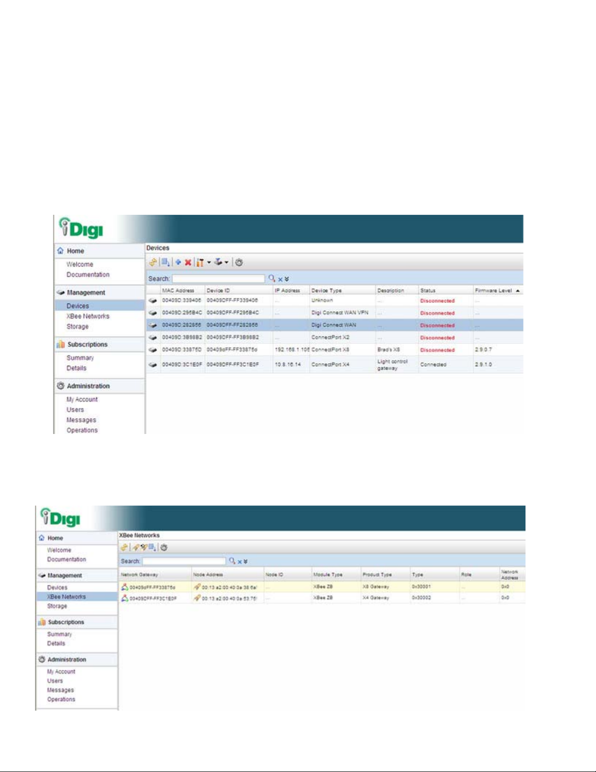
The iDigi Platform is a particularly attractive platform for configuring managing XBee devices
behind the gateway. It displays all nodes on the XBee network with the ability to query for node
profiles, node descriptors, connected endpoints, radio configuration settings radio statistics,
bindings, and more.
33
Page 34

Introduction
For more information on the iDigi Platform as an remote management interface, see these
resources:
"Remote management settings" on page 164. This section shows how to configure
settings within Digi devices so that they can be handled through a remote device
manager such as the iDigi Platform.
"Configuration through the iDigi Platform" on page 55.
"Monitoring capabilities from the iDigi Platform" on page 183
iDigi tutorials and guides
34
Page 35
Introduction
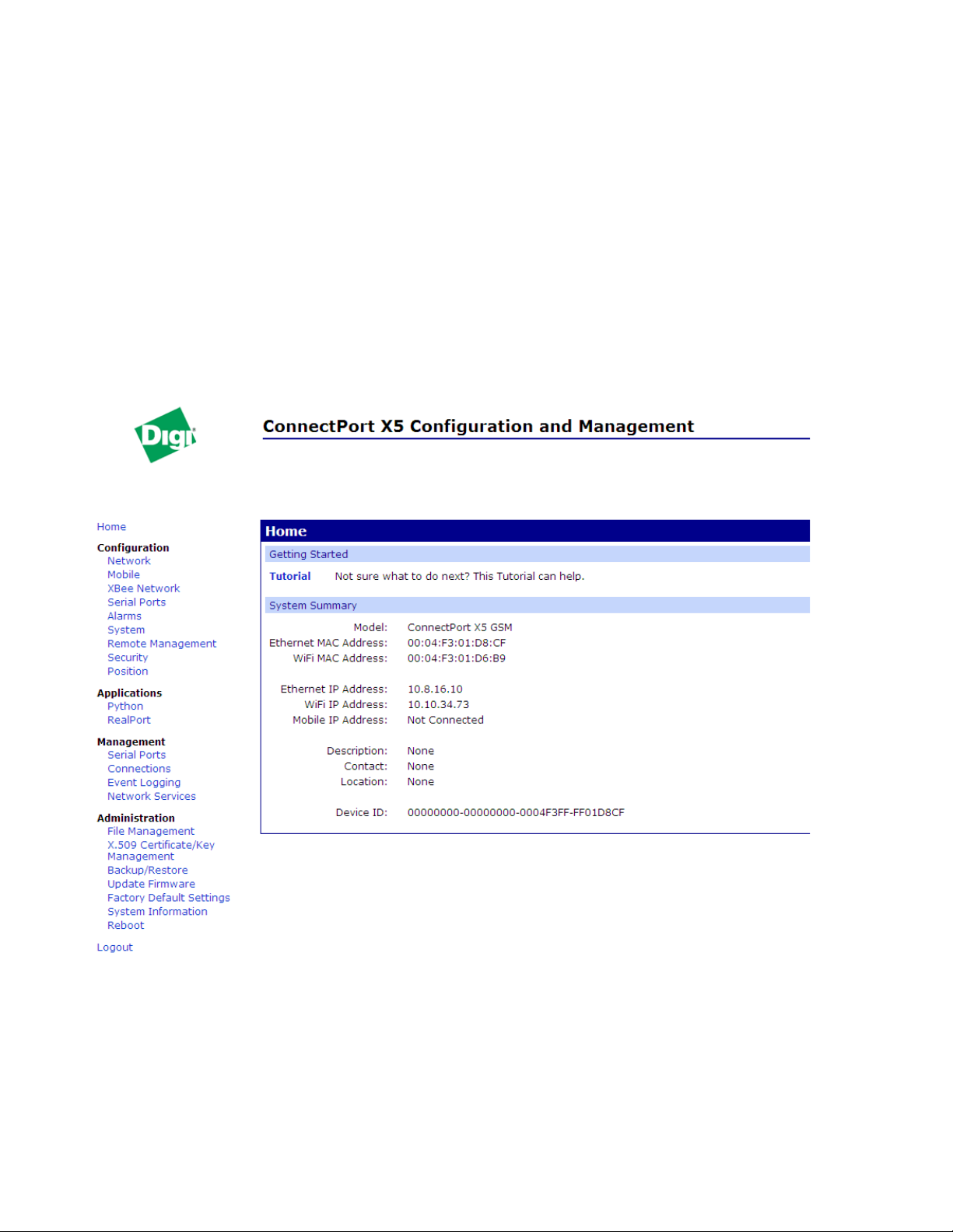
Web interface
A web interface is provided as an easy way to configure and monitor Di gi devices. Configurable
features are grouped into several categories. These categories vary by product; examples include
Network, Serial Port, Alarms, System, Remote Management, Security. Most of the configurable
features are arranged by most basic settings on a page , wi th associated and advanced settings
accessible from that page. Serial-port configurations are classified into port profiles, o r
configuration scenarios that best represents the environ me nt i n which th e Di gi device will be used.
Selecting a particular port profile configures the serial port parameters that are nee ded.
To access the web interface, enter the Digi device’s IP address or host name in a browser’s URL
window. The main menu of the web interface is displayed. For more information, see
"Configuration through the web interface" on page 63. The web interface has a tutorial, accessed
from the Home page, and online help, accessed from the Help link on each page.
Not all settings provided by the command-line interface are displayed in the web interface.
However, the configuration settings in the web interface should be sufficient for most users. If
necessary, settings can be modified later from the command line.
35
Page 36

Introduction
Command-line interface
Digi devices can be configured by issuing commands from the command line. The command-line
interface allows communication directly without a graphical interface. To access the command line
from the Digi Device Discovery utility, click Telnet to command line.
For example, here is a command issued from the command line o assign the IP address to the
Ethernet interface:
#> set network ip=192.168.1.1
The command-line interface provides flexibility for making precise changes to device
configuration settings and operation. It does require users to have experience issuing commands,
and access to command documentation.
The command line is available through Telnet or SSH TCP/IP connections, or through serial port
using terminal emulation software such as Hyperterminal. Access to the command line from serial
ports depends on the port profile in use by the port. By default, serial port command-line access is
allowed.
See "Configuration through the command line" on page 178 fo r more information on this interface .
See the Digi Connect Family Command Referen ce for command descriptions and examples of
entering configuration commands from the command-line interface. In addition, online help is
available for the commands, through the help and ‘?’ command s .
Remote Command Interface (RCI)
Remote Command Interface (RCI) is a programmatic interface for configuring and controlling
Digi devices. RCI is an XML-based request/response protocol that allows a caller to query and
modify device configurations, access statistics, reboot the device, and reset the device to factory
defaults. Unlike other configuration interfaces that are designed for a user, such as the commandline or web interfaces, RCI is designed to be used by a program. RCI access consists of program
calls. A typical use of RCI is in a Java applet that can be stored on the Digi device to replace the
web interface with a custom browser interface. Another example is a custom application running
on a PC that monitors and controls an installation of many Digi devices.
As RCI is designed to be used by a program, it is useful for creating a custom configuration user
interface, or utilities that configure or initialize devices through external programs or scripts.
RCI uses HTTP as the underlying transport protocol. Depending on the network configuration, use
of HTTP as a transport protocol could be blocked by some firewalls.
RCI is quite complex to use, requiring users to phrase configuration requests in Extensible Markup
Language (XML) format. It is a “power-user” option, intended more for users developing their
own user interfaces, or for users implementing embedded control (and thus potent ially using RCI
over serial) than for end-users with limited knowledge of device programming.
Not all actions in the web interface have direct equivalents in RCI. Therefore, it may not be easy
for some end-users to determine what needs to be sent through XML for a particular style of
request.
For more details on RCI, see the Digi Connect Integration Kit and the Remote Command Interface
(RCI) Specification.
36
Page 37

Introduction
Simple Network Management Protocol (SNMP)
Simple Network Management Protocol (SNMP) is a protocol for managing and monitoring
network devices. The SNMP architecture enables a network administrator to manage nodes-servers, workstations, routers, switches, hubs, etc.--on an IP network; manage network
performance, find and solve network problems, and plan for network growth. Dig i devic es support
SNMP Versions 1 and 2.
SNMP is easy to implement in extensive networks. Programming new variables and “dropping in”
new devices in a network are easy. SNMP is widely used. It is a standard interface that integrates
well with network management stations in an enterprise environment. While its capabilities are
limited to device monitoring and display of statistics in Digi devices, read/write capabilities are
expected to be added to Digi devices in future releases.
However, because device communication is UDP-based, the communication is not secure. If more
secure communications with a device are required, use an alternate device interface. SNMP does
not allow for certain task that can be performed from the web interface, such as file management,
uploading firmware, or backing up and restoring configuration s. Compa r ed to th e web or
command-line interfaces, SNMP is limited in its ability to set specific parameters, such as set port
profile, is not possible.
Accessing the SNMP interface requires a tool, such as a network management station. The
management station relies on an agent at a device to retrieve or update the information at the
device, including Device configuration, status, and statistical information. This information is
viewed as a logical database, called a Management Information Base (MIB). MIB modules
describe MIB variables for a variety of device types and computer hardware and software
components.
A variety of resources about SNMP are available, including reference books, overviews, and other
files on the Internet. For an overview of the SNMP interface and the components of MIB-II, go to
http://www.rfc-editor.org/rfcsearch.html, and se arch for MIB-II. From the results, locate the text
file describing the SNMP interface, titled Management Information Base for Network
Management of TCP/IP-based internets: MIB-II. The text of the Digi enterprise MIBs can also be
displayed.
For additional discussion of using SNMP as a device monitoring interface, see "Monitoring
Capabilities from SNMP" on page 208.
37
Page 38

Monitoring capabilities and interfaces
Monitoring Digi devices includes such tasks as checking device status, checking runtime state,
viewing serial port operations, and reviewing network statistics, and managing their connections.
There are several interfaces for monitoring Digi devices and managing their connections.
As with device configuration, there are several interfaces available for monitoring Digi devices,
including, the web interface embedded with the product, SNMP, command-line interface, and the
iDigi Platform. These interfaces are covered in more detail in Chapter 4, "Monitor and manage
Digi devices"
The iDigi Platform
In the iDigi Platform, monitoring capabilities can be sorted by the server and the de vices mana ged
by the server. The information is available in logs and can be generated into reports. When
available, the reports post linked to tals that can be drilled back to the origina l devices that mak e up
the activity of the report.
The iDigi Platform is well-suited to managing Conn ectPort X5 Family de vices and the netw orks in
which the devices reside. Advantages include the ability to view an entire network, and multiple
networks, at once, and ease in viewing signal strength, link quality, and alarms
Introduction
Web interface
The web interface has several screens for monitoring Digi devices:
Network Status
Mobile connection status
Serial Port Management: for each port, the port’s description, current profile, and
current serial configurati on.
Connections Management: A display of all active system connections.
System Information: general device information; serial port information for each port,
including the port’s description, current profile, and current serial configuration (the
same information displayed by choosing Serial Port Management); and network
statistics.
Command-line interface
Several commands can be issued from the command line to monitor devices. For a review of these
commands and what they can provide from a device-monitoring perspective, see "Monitoring
capabilities from the command line" on page 204.
SNMP
Monitoring capabilities of SNMP include managing network performance, gathering device
statistics, and finding and solving network problems. For more information on using SNMP for
device-monitoring purposes, see "Monitoring Capabilities from SNMP" on page 208.
38
Page 39

Device administration
Periodically, administrative tasks need to be performed on Digi devices, such as uploading and
managing files, changing the password for logging onto the device, backing up and restoring
device configurations, updating firmware, restoring the configuration to factory defaults, and
rebooting.
As with configuration and monitoring, administration can be done from a number of interfaces,
including the web interface, command line, and the iDi gi Platform. See Chapter 5, "Digi device
administration" for more information and procedures.
Introduction
39
Page 40

Hardware installation
Hardware installation
CHAPTER 2
This section details requirements and recommendations for installing ConnectPort X5 products,
including the cable harness, mounting requirements, and antennas.
There are several versions of ConnectPort X5 products:
ConnectPort X5 K: This model is a development kit that comes with a development
cable and antennas. It also has a slot in the side for customers to install their own SIM
card. It is intended for development use.
ConnectPort X5 R: This model is a production unit. Digi installs customer-specific
SIM cards into each unit and ensures that the unit is environmentally sealed. Customer
are responsible for providing their own cable harness and antennas; cable harness
guidelines are later in this chapter. All connectors must be sealed to maintain IP67 and
other environmental ratings.
ConnectPort X5 Fleet: This model is a production unit with internal antennas. Digi
recommends this version of the product if using an X5R would require more than 3
meters of cable length. The customer is responsible for providing their own cable
harness.
40
Page 41

Cable harness guidelines
Digi does not provide a cable harness for the ConnectPort X5 R. Instead, you must design and
create a cable harness that follows the guidelines and pinouts in this section.
ConnectPort X5 main connector
The main connector on the ConnectPort X5 R is a 23-pin IP67 connector from Tyco. The cable
harness must use the mating plug and pins listed in the following table to connect to the X5R unit.
ConnectPort X5 R 23-pin Connector and Mating Connector Part Numbers
ConnectPort X5 Main Connector 1-776087-1
Mating Connector 770680-1
Hardware installation
Part Tyco Part Number
Mating Connector Wire Relief 776464-1
Mating Connector Pins 770854-3
Mating Connector Plugs 770678-1
Mating Connector Crimper 58529-1
The connector pins accept 20-16AWG wire.
If the rubber seal of the mating connector is accidently perforated in an unpopulated location
during cable assembly , th e hole can be filled with a plug if the connector needs to ma intain an IP67
rating.
The cable harness should be restrained every 7-9” to prevent vibration-related damage.
The recommended minimum cable bend radius is five times the cable diameter.
Use dielectric grease on the main connector contacts when connecting your cable harness to the X5
to prevent fretting on the cont acts.
41
Page 42

Hardware installation
ConnectPort X5 R connector pins
Pins for the ConnectPort X5 R connector are arranged as follows. Pin 1 is in the upper-left corner.
42
Page 43

Hardware installation
Pinouts
Pinouts for the ConnectPort X5 R and ConnectPort X5 Fleet are as follows.
Pin # Signal Name
1 Digital Ground
2 NC, for internal Digi use
3Serial RXD
4Serial RTS
5 J1708-
6CAN_L
7 Ethernet TX-
8 Ethernet RX-
9 Chassis Ground
10 Serial TXD
11 Serial CTS
12 J1708+
13 CAN_H
14 Ethernet TX+
15 Ethernet RX+
16 Vin
17 Ignition
18 Reset
19 DIO0
20 DIO1
21 DIO2
22 DIO3
23 NC
43
Page 44

Available interfaces on the ConnectPort X5 main connector
Serial
Chassis ground
CAN/J1939
J1708
Ignition sense line
Digital I/O
lines
Ethernet
Reset
Power/
digital
ground
Connector
ConnectPort X5 R has the following interfaces available on its main connector:
Hardware installation
Power/digital ground: Power and digital ground should be twisted pair and must be
connected to a fused power supply. See hardware specs for required voltages and current
draw.
CAN/J1939: Please refer to the CAN/J1939 specification for proper wiring. The
ConnectPort X5 R assumes that it is plugged into a terminated bus that meets all CAN/
J1939 specifications and requirements.
J1708: Please refer to the J1708 specification for proper wiring. The ConnectPort X5 R
assumes that it is plugged into a terminated bus that meets all J1708 specifications and
requirements.
5-wire RS232 Serial (TXD, RXD, RTS, CTS, GND): The serial drain wire should be
connected to chassis ground.
Ethernet (10 Mbps or 100 Mbps): The Ethernet cable must conform to networking
cable specifications. The Ethernet drain wire should be connected to chassis ground.
Four Digital Input/Output lines: The pins are limited to a voltage range of 0 to
+36VDC. The digital inputs are Schmitt trigger in puts with VT+ = 1.5V (typ) and VT- =
1V (typ). The digital outputs use sinking output drivers (an external pull-up is required).
The outputs can sink a maximum of 0.5A and are protected by an in-line, self-resettable
fuse.
44
Page 45

Hardware installation
An ignition sense line, part of the power management strategy, used to unconditionally
wake a device from a low-power state. To support ignition detect, the ignition pin must
be wired into the vehicle’s ignition detect signal. This pin has a digital input signal for
detecting ignition supply voltage. Voltage range: 0 to +48VDC. The pin has protection
for short, positive and negative overvoltage conditions. VIH = 7V , VIL = 2V. This line is
open collector.
Chassis ground: To provide chassis isolation, the metal enclosure and digital ground
are not directly tied. The main reason for this was to avoid potentially large vehicle
return currents from flowing through digital ground, if the product is mounted directly
to a vehicle chassis. To prevent static charge build-up, the two grounds are connected
through a high value resistance, to create a discharge path. The chassis ground should
also be connected to the serial an d Ethernet drain wires.
Reset: This pin is limited to voltage range 0 to +36VDC. The input structure uses a
Schmitt trigger with VT+ = 1.5V (typ) and VT- = 1V (typ). Digi does not recommend
adding this to your cable harness. For more information on use of this reset pin and the
available options for performing a reset, see "Restore a device configuration to factory
defaults" on page 215.
45
Page 46

Mounting the ConnectPort X5 to a vehicle
ConnectPort X5 R
The ConnectPort X5 R has flexible mounting holes to allow installat ion in a va riety of lo cations to
many different surface materials. The arrows in the diagram indicate mounting hole locations.
Hardware installation
Use at least four (4) ¼” bolts to mount the ConnectPort X5 R unit. The ConnectPort X5 R unit is
IP67 rated; allowing for it to be mounted inside or outside. The ConnectPort X5 R enclosure is
made of bare aluminum, and the TNC connectors and nuts are made of nickel-plated brass.
The ConnectPort X5 Main Connector and TNC connectors must be mated to maintain IP67 rating.
The product is not to be installed on a dashboard or on the lower-chassis of a vehicle.
46
Page 47

ConnectPort X5 Fleet
To be provided.
Hardware installation
47
Page 48

Antennas
To WIFI
connector
To Cellular
connector
(second
from left)
To XBee
connector
To GPS
connector
(second
from right)
Cellular/GPS can be handled through a
combined antenna, as shown, or separate
antennas.
ConnectPort X5 R
The ConnectPort X5 R has four antenna options: Wi-Fi, Cellular and GPS, and XBee. The order of
those antennas is shown in the following diagram. The antennas must be mounted at least 8 inches
(20 cm) apart. If your application requires antenna cables longer than 3 meters, Digi recommends
the ConnectPort X5 Fleet product instead. That product has internal an tennas so antenna
performance will not be significantly degraded due to l ong cables.
Antenna locations
Hardware installation
48
Page 49

Hardware installation
Certified Antennas for ConnectPort X5 R
The following antennas were used during certification of the ConnectPort X5 R and are included
with the ConnectPort X5 R kit. You must procure your own antennas for the ConnectPort X5 R
product. If choosing to use other antennas than these, choose antennas that conform to these
specifications.
Antenna Manufacturer Manufacturer part
number
Wi-Fi Taoglas WS.01.301351
Cellular/GPS
Taoglas
MA.104.A.A301351.B301311 Frequency range Quad band;
Specifications
Frequency range 2400-2500 MHz
5150-5350 MHz
Gain 4.1 dB @2400 MHz
4.7 dB @5000 MHz
Antenna size Height: 1.14 in (2.9 cm)
Diameter: 2.05 in (5.21 cm)
Mounting method 18 mm screw mount (.3149 in)
Cable length 9.84 feet (3 meters)
Connector type RPTNC
CDMA: 824-896 MHz
GSM: 880-960 MHz
PCS: 1850-1990 MHz
DCS: 1710-1880 MHz
Gain 30 dB typical
Gain at Zenith: 2. dBi min
Gain at 10 degrees elevation: -
4.0 dBi minimum
Axal ratio: 2.0 dB maximum
Antenna size Height: 1.14 in (2.9 cm)
Diameter: 2.05 in (5.21 cm)
Mounting method 3.149 in (18 mm) screw in
dipole mount
Cable length 9.84 feet (3 meters)
Connector type Cellular: TNC (standard
polarity TNC)
GPS: RPTNC (reverse
polarity TNC)
49
Page 50

Hardware installation
Antenna Manufacturer Manufacturer part
number
XBee Laird RD2458-5-RA-TNC
Bobbintron
AN2400-19B01RART Frequency range 2400-2500 MHz
Specifications
Frequency range 2400 - 2483 MHz
Gain 3 dBi @ 2400 MHz
5 dBi @ 5000 MHz
Antenna size 6.8 in (17.27cm)
Mounting method N/A
Connector type RP TNC
Gain 3 dBi
Antenna size 6.8 in (17.27cm)
Mounting method 3.149 in (18 mm) screw-in
dipole mount
Connector type RP TNC
50
Page 51

ConnectPort X5 Fleet
To be provided.
Hardware installation
51
Page 52

ConnectPort X5 K development kit
The ConnectPort X5 K is a development kit for lab use only. The kit contains:
A ConnectPort X5 R with a slot for installing a SIM card. The ConnectPort X5 K is a
development kit for lab use only.
Development Cable and power cord. The development cables provide access to all
interfaces on your device.
Wi-Fi antenna
Cellular/GPS antenna
XBee antenna
Quick Start Guide and links to all documentation needed to being development on your
unit.
The table shows the part numbers for the development cables and antennas.
Description Digi Part Number
Hardware installation
CBL, X5 Development 76000781
Wi-Fi antenna 76000783
Cellular (GSM)/GPS antenna 76000782
XBee antenna 76000784
52
Page 53

Configure Digi devices
Configure Digi devices
CHAPTER 3
This chapter describes how to configure a Digi device. It covers these topics:
"Default IP address and methods for assigning an IP address" on page 54
"Configuration through the iDigi Platform" on page 55
"Configuration through the web interface" on page 63
"Configuration through the command line" on page 178
"Configuration through Simple Network Management Protocol (SNMP)" on page 181
"Batch capabilities for configuring multiple devices" on page 181
53
Page 54

Configure Digi devices
Default IP address and methods for assigning an IP address
All products that have a cellular (WAN) interface ship with static IP address for the Ethernet port
of 192.168.1.1 and DHCP server enabled by default. Plugging the Conn ectPort X5 device into a
switch or network to which a laptop computer is connected allows direct access to the web
interface for configuration. The Ethernet port of the laptop should be configured to automatically
receive an IP address and DNS server address.
All products that only have an Ethernet or Wi-Fi (LAN) interface ship with DHCP client enabled
by default. Accessing the web interface on the se prod ucts is most easily don e by con nectin g it to a
LAN that has a DHCP server.
T o discover which IP address has been assigned to the device, use the Device Discovery Utility for
Windows, available on the Digi Support site. See installation instructions on page 63.
There are several ways to assign an IP address to a Digi device, described on the following pages:
Use Dynamic Host Configuration Protocol (DHCP) from the web interface.
Use Automatic Private IP Addressing (APIPA), also known as Auto-IP.
Configure an IP address using DHCP
An IP address can also be configured using Dynamic Host Configuration Protocol (DHCP). DHCP
is an Internet protocol for automating the configuration of computers that use TCP/IP. DHCP can
be used to automatically assign IP addresses and deliver TCP/IP stack configuration parameters.
As mentioned previously, all products that have a cellular (WAN) interface ship with static IP
address for the Ethernet port of 192.168.1.1 and DHCP server enabled by default. All products that
only have an Ethernet or Wi-Fi (LAN) interface ship with DHCP client enabled by default.
For more information on DHCP server configuration, see "DHCP server settings" on page 75.
Configure an IP address using Auto-IP
The standard protocol Automatic Private IP Addressing (APIPA or Auto-IP) automatically assigns
the IP address from a group of reserved IP addresses to the device on which Auto-IP is installed.
Use Digi Device Discovery or DHCP to find the Digi device and assign it a new IP address that is
compatible with your network. Once the unit is plugged in, Auto-IP automatically assigns the IP
address. Auto-IP addresses are typically in the 169.254.x.x ad dress range.
Test the IP address configuration
Once the IP address is assigned, make sure it works as configured.
1 Access the command line of a PC or other networked device.
2 Issue the following command:
ping ip-address
where ip-address is the IP address assigned to the Digi device. For example:
ping 192.168.2.2
54
Page 55

Configuration through the iDigi Platform
The iDigi Platform is an on-demand service. After creating an iDigi account, you can connect to
the iDigi Platform. There are no infrastructure requirements. Remote devices and enterprise
business applications connect to the iDigi Platform via standards-based Web Services.
Create an Account on iDigi.com
To get started using iDigi, set up an account on the iDigi Platform.
1 Navigate to http://www.idigi.com.
2 Click on the iDigi Platform Login button.
3 Click on the Are you a new user? link and create your account.
Configure Digi devices
55
Page 56
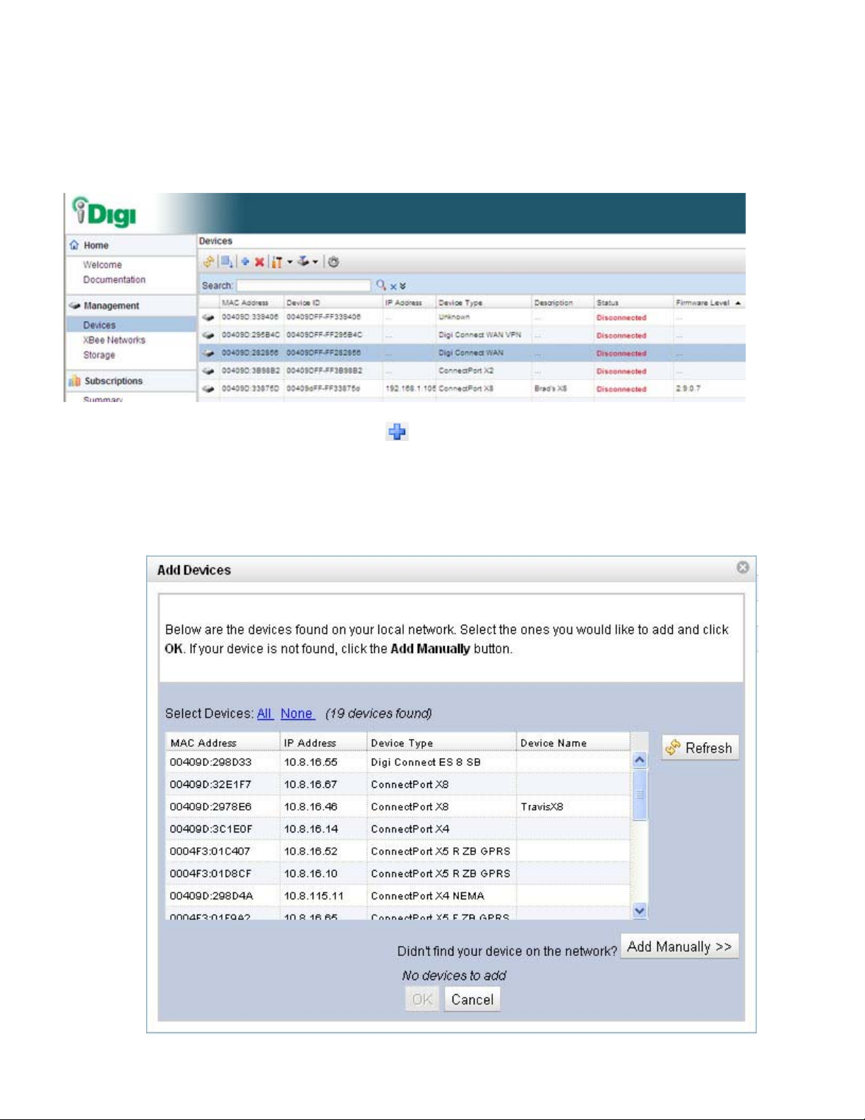
Add the Digi device to the idigi.com Device List
To add your Digi device to the device list, follow these steps:
1 Log into the iDigi.com user portal using the username and password you just created. The
iDigi Platform interface is displayed.
2 In the Devices list, Click the button on the toolbar to display the Add Devices dialog.
Locate and select your device from the list of locally discovered devices and click the OK
button. If your device was not found in the list, check that it is turned on and connected to
the same local network as your PC and click the Refresh button. Adding your device
through automatic discovery informs iDigi about the device and configures that device to
connect to the iDigi Connectivity server.
Configure Digi devices
56
Page 57
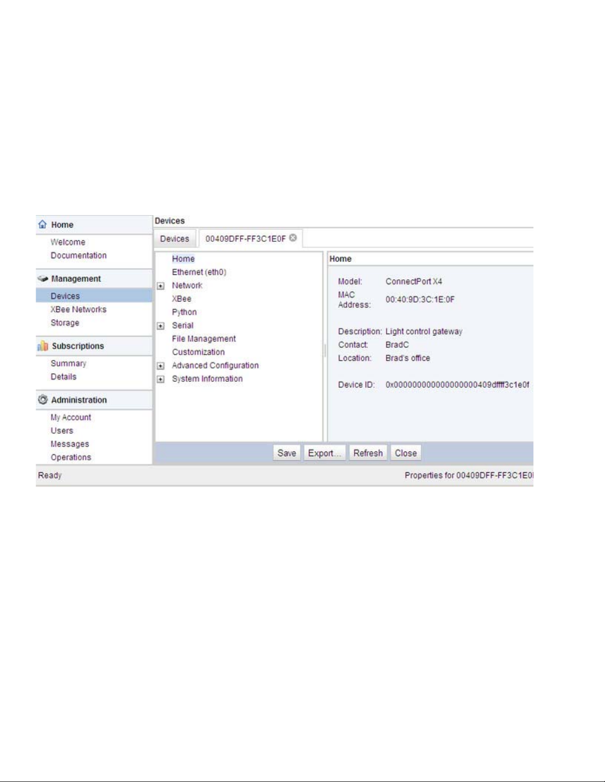
Configure Digi devices
Note
If the device is not locally accessible or cannot be automatically discovered, you can
still add it by clicking the Add Manually button and enter the MAC address found on
the bottom of the device. If you manually add your device however, you must also
configure the device to connect to the iDigi Connectivity Server. See “Manually
configure a Digi device to connect to the iDigi Platform” on page 168.
3 Wait a few moments and click the Refresh button to ensure that your device status is now
Connected.
4 Select y our device and double-click it, or right-click and select Properties.
5 Your device information will load into the iDigi Device Manager.
57
Page 58

iDigi Platform views for configuring and managing Digi devices
The iDigi Platform has several views for configuring and managing network devices.
Device list
The iDigi device list displays all the devices in your network. This view allows for viewing and
accessing devices regardless of their physical location, even devices behind firewalls. From this
view, you can filter and sort device list information, customize the device information displayed,
refresh the information, view messages, select one or more devices to configure, manage, and
monitor., and add/remove devices and groups.
Configure Digi devices
58
Page 59

Configure Digi devices
Device operations menu
In the device list, right-clicking on a selected device displays the device operations menu for
performing key device-management tasks, such as file management, restoring the device to factory
defaults, updating firmware, and displaying device properties. The image shows the operations
menu and the operations available under Administration and Firmware.
59
Page 60

Configure Digi devices
Device properties view
Selecting Properties from the device operations menu displays a system summary of the selected
device, and a menu of configuration settings, similar to the menu on the home page of the web
interface for a Digi device.
XBee Networks view
The iDigi Platform is a particularly attractive platform for configuring managing XBee devices
behind the gateway. The XBee Networks view displays nodes in the context of their XBee
network, including their node ID, the network to which they belon g, physical addresses, their role
in the XBee network (coordinator, router, or end node), their defined parent in the network, and
their current status.
This view has a Search function that allows you to search for any device in the network associated
with any gateway, a convenient function when managing multiple XBee networks with many
nodes.
60
Page 61

Configure Digi devices
Node View
From the XBee Network view, cli ck Basic, Advanced, or Summary to view details about nodes.
The Basic view shows the basic configuration settings for a node.
.
The Advanced view shows more detailed configuration settings for a node.
61
Page 62

Configure Digi devices
The Summary view displays running-state and status information for a node.
For more information on iDigi Platform
To learn more about the iDigi Platform and the services it provides, see the
iDigi Device Management and Web Services Tutorial.
62
Page 63

Configuration through the web interface
Open the web interface
To open the web interface, either enter the Digi device’s URL in a web browser and log on to the
device, if required, or use the Digi Device Discovery utility to locate it and open its web interface.
By entering the Digi device’s IP address in a web browser
1 In the URL address bar of a web browser, enter the IP address of the device.
2 If security has not been enabled for the Digi device, the Home pag e of the web interface is
displayed. If security has been enabled for the Digi device, a login dialog will be displayed.
Enter the user name and password for the device. The default username is root and the
default password is dbps. If these defaults do not work, contact the system administrator
who set up the device. Then the Home page of the web interface is displayed. See
"Organization of the web interface " on page 65 fo r an overview of using the Home page and
other linked pages.
Configure Digi devices
By using the Digi Device Discovery utility
Alternatively, use the Digi Device Discovery Utility to locate the Digi device and open its web
interface.
Install and run the Digi Device Discovery utility
The Digi Device Discovery Utility is available for downloading from the Digi Support site.
If this utility is not already available on your computer, follow these steps.
1 From a browser, go to www.digi.com.
2 Cl ick t he Sup port link and select Diagnostics, Utilities and MIBs.
3 Und er Select Your Product for Support, select your Digi device from the product list
and click Submit.
4 Und er Active Products, select your Digi device from the product list.
5 Und er OS Specific Diagnostics, Utilities and MIBs, select the operating system for
your computer from the list.
6 Select either Device Discovery Utility fo r Windows - Standalone version or
Device Discovery Utility for Windows - Installable version. The standalone version runs
the utility immediately after the download is complete. The installable version installs the
utility on your computer and adds it to a program group named Digi in the Start menu.
7 Cl ick Run on the two dialogs. The standalone version of the utility starts immediately.
For the installable version, an installation wizard is displayed. Follow the prompts to
complete the installation. To start the utility, select
Start > Programs > Digi > Digi Device Discovery > Digi Device Discovery
63
Page 64

Configure Digi devices
Discover devices
From the start menu, select Start > Programs > Digi Connect > Dig i Device Disc overy. The Digi
Device Discovery application is displayed.
Locate the device in the list of devices, and double-click it, or select the Digi device from the list
and select Open web interface in the Device Tasks list.
64
Page 65
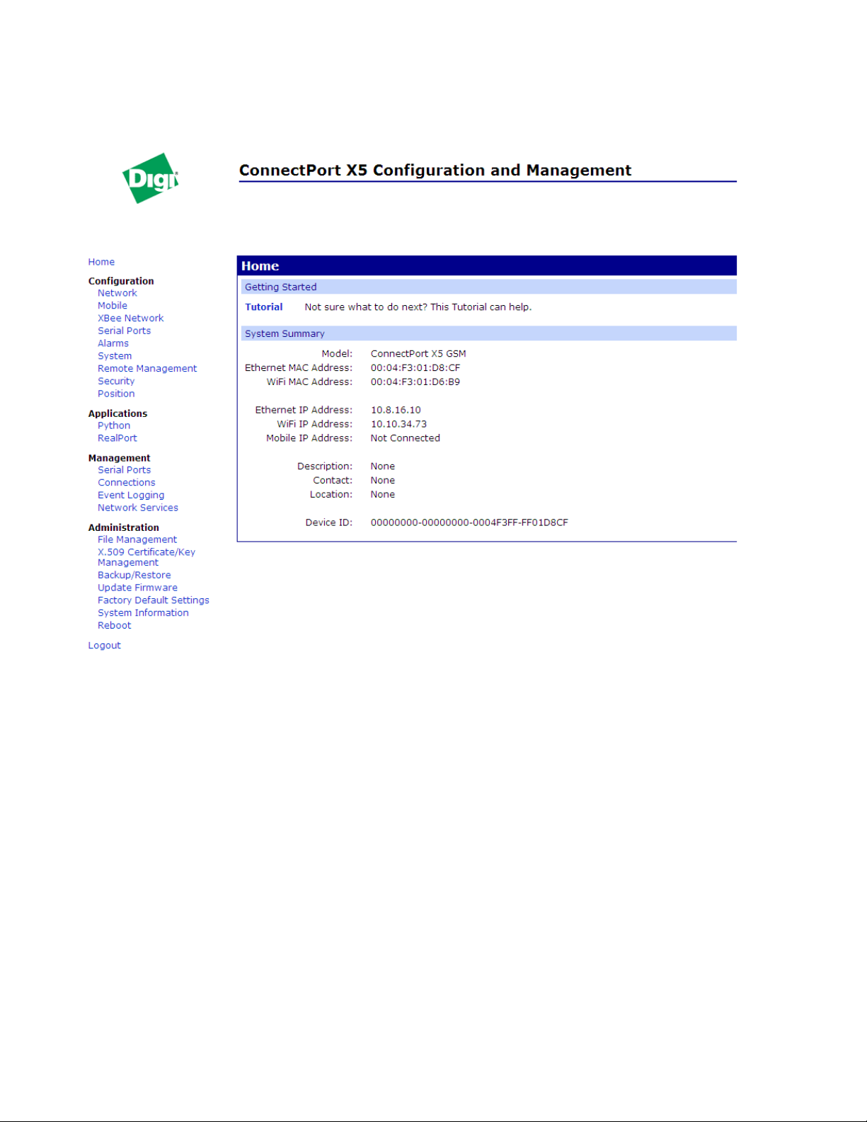
Organization of the web interface
When the web interface is opened, the Home page is displayed.
Configure Digi devices
The Home page
The left side of the Home page has a menu of choices that display pages for configuration,
management, and administration tasks, and to log out of the web interface. This chapter focuses on
the choices under Configuration and Applications. For details on the tasks under
Administration, see Chapter 5, "Digi device administration".
Clicking Logout logs out of a configuration and management session with a Digi device. It does
not close the browser window, but displays a logout window. To finish logging out of the web
interface and prevent access by other users, close the browser window. Or, log back on to the
device by clicking the link on the screen. After 5 minutes of inactivity, the idle timeout also
automatically performs a user logout.
The Getting Started section has a link to a tutorial on configuring and managing Digi device.
The System Summary section notes all available device-description information.
65
Page 66

Configure Digi devices
Configuration pages
The choices under Configuration in the menu display pages for configuring settings for various
features, such as network settings, and serial port settings. Some of the configuration settings are
organized on sets of linked screens. For example, the Network Configuration screen initially
displays the IP Settings, and provides links to Network Services Settings, Advanced Settings, and
other network settings appropriate to the Digi device.
Applications pages
Depending on the Digi device, there may be an Applications menu item for configuring various
applications available for use in the device.
Python: For loading and running custom programs authored in the Python
programming language onto ConnectPort X Family devices.
RealPort: Configures RealPort settings. See page 176.
Apply and save changes
The web interface runs locally on the device, which mean s that th e interfac e always main tains an d
displays the latest settings in the Digi device. On each screen, the Apply button is used to save any
changes to the configuration settings to the Digi device.
Cancel changes
To cancel changes to configuration settings, click the Refresh or Reload button on the web
browser. This causes the browser to reload the page. Any changes made since the last time the
Apply button was clicked are reset to their original values.
Restore the Digi device to factory defaults
The device configuration can be reset to factory defaults as needed during the configuration
process. See "Restore a device configuration to factory defaults" on page 215.
Online help
Online help is available for all screens of the web interface, and for common configuration and
administration tasks. There is also tutorial available on the Home page.
66
Page 67

Change the IP address from the web interface, as needed
Normally, IP addresses are assigned to Digi devices either through DHCP or the Digi Device Setup
Wizard.
This procedure assumes that the Digi device already has an IP address and you simply wan t t o
change it.
1 Op en a web browser and enter the Digi device’s current IP address in the URL address bar.
2 If security is enabled for the Digi device, a login prompt is displayed. Enter the user name
and password for the device. The default username is root and the default password is dbps.
If these defaults do not work, contact the system administrator who set up the device.
3 Cl ick Network to access the Network Configuration page.
4 On the IP Settings page, select Use the following IP address.
5 Enter an IP address (and other network settings), then click Apply to save the configuration.
Configure Digi devices
67
Page 68

Network configuration settings
The Network configuration pages include:
Ethernet IP settings: For viewing IP address settings and changing as needed. See
page 70.
WiFi IP settings: For setting the IP address used for wireless LAN communication. See
page 70.
WiFi L AN settings: For setting basic options for wireless LAN devices such as
network name and network connection options. See page 71.
WiFi Security settings: For setting authentication and encryption options for wireless
LAN devices. See page 72.
WiFi 802.1x Authentication settings: Detailed authentication settings for IEEE 802.1x
authentication for wireless LAN devices. See page 74.
DHCP Server settings: For configuring a DHCP server to allow other devices or hosts
on this network to be assigned dynamic IP addresses. See page 75.
Network Services settings: Enable and disables access to various network services,
such as ADDP, RealPort and Encrypted RealPort, Telnet, HTTP/HTTPS, and other
services. See page 79.
Configure Digi devices
Dynamic DNS Update settings: For configuring a Dynamic DNS (DDNS) service that
allows a user whose IP address is dynamically assigned to be located by a host or
domain name. See page 82.
IP Filtering settings: For configuring the Digi Cellular Family device to only accept
connections from specific and known IP addresses or networks. See page 85.
IP Forwarding settings: For configuring the Digi Cellular Family device to forward
certain connections to other devices. This is also known as Network Address
Translation (NAT) or Port Forwarding. See page 86.
IP Network Failover settings: provides a dynamic method for selecting and
configuring the default gateway for the Digi device using a set of rules and link tests to
determine whether a particular network interface can be used to communicate with a
specified destination. See page 89.
Socket Tunnel settings: For configuring a socket tunnel, used to connect two network
devices: one on the Digi Cellular Family device’s local network and the other on the
remote network. See page 93.
Virtual Private Network (VPN) settings: For configuring Virtual Private Networks,
which are used to securely connect two private networks together so that devices may
connect from one network to the other network using secure channels. See page 94.
68
Page 69

Configure Digi devices
IP Pass-through settings: Configures a Digi Cellular Family device to pass its mobile
IP address directly through and to the Ethernet device (router or PC) to which it is
connected through the Ethernet port. The Digi Cellular Family device becomes
transparent (similar to the behavior of a ca bl e o r DSL mo de m) t o p r ov id e a brid ge from
the mobile network directly to the end device attached to the Digi Cellular Family
device. See page 94.
Host List settings: Adds or removes entries from the host list. For DialServ, the host list
provides a means to map a phone number (in the local name field) to a network
destination, (in the “resolves_to” field). See page 105.
Virtual Router Redundancy Protocol (VRRP) settings: For configuring a number of
routers to represent a virtual router, which simplifies configuration of hosts on a
network.
Advanced Network Settings: Configures the Ethernet Interface speed and mode, TCP/
IP settings, TCP keepalive settings, and DHCP settings. See page 107.
Alternatives for configuring network communications
There are three ways a Digi device can be configured on the network.
Using dynamic settings: All network settings will be assigned automatically by the
network, using a protocol called DHCP. Contact your network administrator to find out
if a DHCP server is available.
Using static settings: All network settings are set manually and wil l not chan ge. The IP
address and subnet mask are mandatory . The rest are not mandatory, but may be needed
for some functions. Contact your network administrator for the required values.
Using Auto-IP: Auto-IP assigns an IP address to the Digi device immediately after it is
plugged in. If running DHCP or ADDP, the Auto-IP address is overridden and a network
compatible IP address is assigned, or a static IP address can be assigned.
Even if a DHCP server is available, the device configuration may work better with static settings.
Once set, static settings will not change, so you and ot her network devices can al ways find the Digi
device by its IP address. With dynamic settings, the DHCP server can change the IP address. This
can happen frequently or infrequently depending on how your network administrator has
configured the network.
When the IP address does change, you and other network devices configured to talk to the Digi
device can no longer access the device. In this case, the Digi device must be located the Digi
Device Discovery utility, and other network devices that need to communicate with the Digi device
must be reconfigured.
69
Page 70

Configure Digi devices
Ethernet IP settings
The Ethernet IP Settings page configure how the IP address of the Digi device is obtained, either
by DHCP or by using a static IP address, subnet mask, and default gateway. For more information
about how these settings are assigned and used in your organization, contact your network
administrator.
Obtain an IP address automatically using DHCP: When the Digi device is rebooted,
it will obtain new network settings.Use the Digi Device Setup Wizard to find the Digi
device, since it will likely have a new address.
Use the following IP Address: Choose this option to supply static settings. An IP
address and Subnet mask must be entered. Other items are not mandatory, but may be
needed for some functions (such as talking to other networks).
IP Address: An IP address is like a telephone number for a computer. Other network
devices talk to this Digi device using this ID.
The IP address is a 4-part ID assigned to network devices. IP addresses are in the form
of 192.168.2.2, where each number is between 0 and 255.
Subnet Mask: The Subnet Mask is combined with the IP address to determine which
network this Digi device is part of. A common subnet mask is 255.255.255.0.
Default Gateway: IP address of the computer that enables this Digi device to access
other networks, such as the Internet.
Enable AutoIP address assignment: With AutoIP enabled, the Digi device will
automatically self-configure an IP address when an address is not available from other
methods, for example, when the Digi device is configured for DHCP and a DHCP
server is not currently available.
WiFi IP settings
The WiFi IP settings configure how the IP address of a Wi-Fi-enabled Digi device is obtained. It
has the same settings as the Ethernet IP settings page.
70
Page 71

Configure Digi devices
WiFi LAN settings
Digi devices with Wi-Fi (wireless LAN) capability contain a wireless network interface that may
be used to communicate to wireless networks using 802.11b/g technology. Contact your
administrator or consult wireless access point documentation for the settings required to setup the
wireless LAN configuration. Settings include:
Network name: The name of the wireless network to which the wireless device should
connect. In situations with multiple wireless networks, this setting allows the device to
connect to and associate with a specific network. The network name is referred to as the
SSID (service set identifier). If the network name is left blank, the device will search for
wireless networks and connect to the first available network. This is useful if a specific
network name does not need to be used as the device will select the first available
network.
Connection method: The type of connection method this device uses to communicate
on wireless networks. Choose from:
– Connect to any available wireless network: Use this setting to allow the device to
access any network. The device can either access point networks or peer-to-peer
wireless networks.
– Connect to access point (infrastructure) networks only: Use this setting if the
wireless network that this device needs to connect to is composed of wireless access
points. This is typically the most popular method for connecting to wireless networks.
– Connect to peer-to-peer (ad-hoc) networks only: Use this setting if all dev ices on the
wireless network connect to and communicate with each other. This is known as peerto-peer in that there is no central server or access point. Each system communicates
directly with each other system.
Country: The country in which this wireless device is being used. The channel settings
are restricted to the legal set for the selected country.
Channel: The frequency channel that the wireless radio will use. Select Auto-Scan to
have the device scan all frequencies until it finds one with an available access point or
wireless network it can join.
Transmit Power: The transmit power level in dBm.
Enable Short Preamble: Enables transmission of wireless frames using short
preambles. If Short Preamble is supported in the wireless netw ork, enabling it can boost
overall throughput.
71
Page 72

Configure Digi devices
WiFi security settings
The WiFi security settings specify the wireless security settings that the wireless network uses.
Multiple security and authentication modes may be chosen depending on the configuration of the
access point or wireless network. The wireless device will automatically select and determine the
authentication and encryption methods to use while associating to the wireless network. If the
wireless network does not use security and uses an Open Network architecture, these settings do
not need to be modified.
Note that WPA settings require that the device communicate to Access Points and is not valid
when the Connection Method is set to Connect to wireless systems using peer-to-peer
(ad-hoc). Also, WPA pre-shared key (WPA-PSK) security is only valid when a specific
Network Name or SSID is being used.
Network Authentication: The authentication method or methods used for wireless
communications.
–
Use any available authentication method: Enables all of the methods. The
actual method used will be determined by the capabilities of the wireless network.
–
Use the following selected method(s): Selects one or more authentication
methods for wireless communications.
Open System: IEEE 802.11 open system authentication is used to establish a
connection.
Shared Key: IEEE 802.11 sha red key authentication is used to establish a
connection. At least one WEP key must be specified in order to use shared key
authentication.
WEP with 802.1x authentication: IEEE 802.1x authentication (EAP) is used to
establish a connection with an authentication server or access po int. Wired
Equivalent Privacy (WEP) keys are dynamically generated to encryp t dat a ov er the
wireless network.
WPA with pre-shared key (WPA-PSK): The Wi-Fi Protected Access (WPA)
protocol is used with a pre-shared key (PSK). The PSK is calculated using a
passphrase and the network SSID.
WPA with 802.1x authentication: The WPA protocol and IEEE 802.1x
authentication (EAP) is used to establish a connection with an authentication serve r
or access point. Encryption keys are dynamically generated to encrypt data over the
wireless link.
Cisco LEAP: Lightweight Extensible Authentication Protocol (LEAP) is used to
establish a a connection with an authentication server or access point. Wired
Equivalent Privacy (WEP) keys are dynamically generated to encryp t dat a ov er the
wireless link. A user name and password must be specified to use LEAP.
72
Page 73

Configure Digi devices
Data Encryption: Multiple encryption methods can be selected.
–
Use any available encryption method: enables all of the methods. The actual
method used will be determined by the capabilities of the wireless network.
–
Use the following selected method(s): Selects one or more encryption
methods.
Open System: No encryption is used over the wireless link. Open System
encryption is valid only with Open System and Shared Key authentication.
WEP: Wired Equivalent Priv acy (WEP) encryption is used over the wireless link.
WEP encryption can be used with any of the above authentication methods.
TKIP: Temporal Key Integrity Protocol (TKIP) encryption is used over the
wireless link. TKIP encryption can be used with WPA-PSK and WPA with 802.1x
authentication.
CCMP: CCMP (AES) encryption is used over the wireless link. CCMP can be used
WPA-PSK and WPA with 802.1x a uth enti catio n.
WEP Keys
– T ransmit Key: Specify the corresponding key of the encryption key that should be used
when communicating with wireless networks using WEP security.
This device allows up to four wireless keys to be set of ei ther 64 -b it o r 128 -b it
encryption. These keys allow the wireless network to traverse different wireless
networks without having to change the wireless key. Instead, only the transmit key
setting has to be changed to specify which wireless key to send .
– Encryption Keys: Specify 1 to 4 encryption keys to be used when communicating with
wireless networks using WEP security.
The encryption keys should be a set of 10 (64-bit) or 26 (128 -b it) hex adecimal
characters. The encryption key should only contain the c haracte rs A-F, a-f, or 0-9.
Optionally, separator characters, such as '-', '_', or '.' may be used to separate the set
of characters.
WPA PSK (Pre-Shared Key) Passphrase/Confirm: The passphrase that the Wi-Fi
network uses with WPA pre-shared keys. The pre-shared key is calculated
using the passphrase and the SSID. Therefore, a valid network name must
have been previously specified. In the Confirm field, reenter the passphrase.
Username/Password/Confirm: The username and password combination used to
authenticate on the network when using these authentication methods:
WEP with
802.1x authentication, WPA with 802.1x authentication, or LEAP. In the
Confirm field, reenter the password.
73
Page 74

Configure Digi devices
WiFi 802.1x authentication settings
These settings are not required based on the current Wi-Fi authentication settings. They are only
configurable when WEP with 802.1x authentication or WPA with 802.1x authentication are
enabled on the WiFi Security Settings tab.
EAP Methods: These are the types of Extensible Authentication Protocols (EAP) or
outer protocols that are allowed to establish the ini tial connection with an authenticatio n
server or access point. These are used with WEP with 802.1x authentication and WPA
with 802.1x authentication.
– PEAP: Stands for “Protected Extensible Authentication Protocol.” A username and
password must be specified to use PEAP.
– TLS: Stands for “ T ransport Layer Security.” A client certificate and private key must be
installed in order to use TLS.
– TTLS: Stands for “Tunneled Transport Layer Security.” A username and password
must be specified to use TTLS.
PEAP/TTLS Tunneled Authentication Protocols: These are the types of inner
protocols that can be used within the encrypted connection established by PEAP or
TTLS.
These Extensible Authentication Protocols (EAP) can be used with PEAP or TTLS.
– GTC: Generic Token Card
– MD5: Message Digest Algorithm.
– MSCHAPv2: Microsoft Challenge response Protocol version 2.
– OTP: One Time Password
These non-EAP protocol s that can be used with TTLS.
– CHAP: Challenge Response Protocol
– MSCHAP: Microsoft Challenge response Protocol
– TTLS MSCHAPv2: TTLS Microsoft Challenge response Protocol version 2.
– PAP: Password Authentication Protoco l
Client Certificate Use: When the TLS is protocol is enabled, a client certificate and
private key must be installed on the Digi device.
– Certificate: Click Browse to select a client certificate file. Then click the next Browse
to select a private key file.
– Private Key File: If the private key file is encrypted, a password must be specified.
Trusted Certificates: Adds and lists trusted certificates.
– Ve rify server certificates: Enable to verify that certificates received from an
authentication server or access point are signed by a trusted certificate authority (CA).
Standard CAs are built in. Additional trusted certificates may be added.
– T rusted Certificate File: To add additional trusted certificates, click Browse to select a
certificate file to upload to the Digi device, then click Upload.
Installed Certificates: Shows which client certificates have been added and are in use.
74
Page 75

Configure Digi devices
DHCP server settings
The DHCP server feature can be enabled in a Digi device to allow other devices or hosts on this
network to be assigned dynamic IP addresses. This DHCP server supports a single su bnetwork
scope.
For the DHCP server to operate, the Digi device must be configured to use a static IP address. For
information on how to configure static IP settings, see "Ethernet IP settings" on page 70.
DHCP terminology
Some key DHCP terms involved in configuring a DHCP server include:
scope
A scope is the full consecutive range of possible IP addresses for a network. A scope typically
defines a single physical subnet on your network, to which DHCP services are offered. A scope
is the primary way for the DHCP server to manage distribution and assignment of IP addresses
and related configuration parameters to its clients on the network.
exclusion range
An exclusion range is a limited sequence of IP addresses within a scope, excluded from DHCP
service offerings. Exclusion ranges assure that any addresses in these ranges are not offered by
the server to DHCP clients on your network.
address pool
After the scope is defined and exclusion ranges are applied, the remaining addresses form the
available address pool within the scope. The addresses in this pool are available for dynamic
assignment by the server to DHCP clients on your network.
lease
A lease is the length of time that the DHCP server specifies, du ri ng which a client host can use
an assigned IP address. When the DHCP server grants a lease to a client, the lease is active.
Before the lease expires, the client typically need s to renew its address lease assignment wi th the
DHCP server. A lease becomes inactive when it expires or it is deleted at the server, or if the
client actively releases the lease. The duration of a lease determines when it will expire and how
often the client needs to renew it with the DHCP server in order to retain the lease.
A DHCP server will never grant a lease to its own address. There is no need for its own address
to be in the exclusion range; the DHCP server simply prot ects its address from being offered.
75
Page 76

Configure Digi devices
grace period
When a DHCP client actively releases a lease, or when the lease expires without be ing renewed
by the client, the DHCP server does not immediately delete the lease record and return the
associated IP address to the available address pool. A grace period is the interval of time for
which the lease record is retained before the DHCP server automatically de letes the record from
its lease list, thereby making the IP address available for lease assignment to another client. The
grace period is not a configurable value. See also the discussion of the grace period and what it
means when the DHCP server is running in "View and manage current DHCP leases" on page
202.
reservation
You may use a reservation to create a permanent address lease assignment by the DHCP server.
Reservations assure that a specified hardware device on the subnet ca n always use the same IP
address. Address lease reservations associate a specific IP address with a specific client's
Ethernet MAC address.
options
Options are other client configuration parameters that the DHCP server can assign when serving
leases to DHCP clients. Most options are defined in RFC 2132. The DHCP server in the Digi
device supports a limited set of options:
– Option 3: Routers on Subnet
– Option 6: DNS Servers
Addresses in the DHCP server settings
The IP address and subnet mask of the DHCP server's scope are the static IP configuration settings
for the Digi device itself.
The default gateway (router) provided to a client with the lease information is the IP address of the
Digi device.
The DNS servers provided to a client with the lease information are the DNS server addresses
configured in the Digi device. These addresses include any DNS server addresses that the Digi
device acquires when it connects to the mobile network.
76
Page 77

Configure Digi devices
DHCP server configuration settings
Here are the configuration settings for the DHCP server. Typically, these settings can be modified
without having to restart the DHCP server for the changes to become effective in the running
server.
Enable Dynamic Host Configuration Protocol (DHCP) Server: Enables the DHCP
server feature on this Digi device. Note that for the DHCP server to operate, the Digi
device must be configured to use a static IP address. For information on how to
configure static IP settings, see "Ethernet IP settings" on page 70.
– Scope Name: The name of the physical network interface associated with the subnet
being served by the DHCP Server. Most Digi device models have a single network
interface, so there is no choice for the scope name. For models that have multiple
network interfaces, such as an Ethernet interface and a Wi-Fi (802.11) int erface, this
DHCP Server may be configured to provide services on either of those interfaces.
– IP Addresses: The starting and ending IP addresses for the scope being served by this
DHCP server. These addresses must be in the same subnet as the Digi device itself.
– Lease Duration: The length of the leases for the scope being served by this DHCP
server. The default lease duration is 24 hours. A DHCP client may request a lease
duration other than this setting, and the DHCP server will grant that request if possible.
Wait specifie d delay before sending DHCP offer reply: The interval of time in
milliseconds to delay before offering a lease to a new client. The default delay is 500ms,
and the range is 0 to 5000ms. Use of this delay permits this Digi device to reside on a
network with other DHCP servers, yet not offer leases to new clients unless the other
DHCP servers do not make such an offer. This provides a measure of protection against
inadvertently connecting a Digi device to a network that is running its own DHCP
server(s), and offering leases to clients in a manner inconsistent with that network.
Check that an IP address is not in use before offering it: When a DHCP client
requests a new IP address lease, before offering an IP address to that client, use “ping”
to test whether that IP address is already in use by another host on the network but is
unknown to the DHCP server . If an IP addr ess is determined to be in use , it is marked as
Unavailable for a period of time, and it will not be offered to any client while in this
state. Enabling this test adds approximately one second of delay before the IP address is
offered to the client, since the “ping” test must not receive a valid reply for that test to
successfully determine that the IP address is not already in use. This option is off
(disabled) by default. This option does not apply to Static Lease Reservations, since the
“ping” test is not used for them.
77
Page 78

Configure Digi devices
Send the DHCP Server IP address as a DNS Proxy Server: This option configures
the DHCP Server to send its IP address to a DHCP client as the first DNS server in its
lease information. This Digi device supports a DNS Proxy feature that will relay DNS
requests and responses between DNS clients and servers. The DNS Proxy is no t a
feature of the DHCP Server itself, but rather it is managed elsewhere in the
configuration settings for this Digi device. For DNS Proxy to be used effectively by a
DHCP client, it must be enabled both in the DHCP server configuration and in the DNS
Proxy settings. For more information, see the description of the Enable DNS Proxy
Service setting in "Advanced network setti ngs" on page 10 7. This option i s on (enabled)
by default.
– Static Lease Reservations: A static lease reservation is a specific IP address paired
with a client's MAC address, whic h reserves the IP address for that client's use only.
This assures that a client always receives a lease for the same IP address and that no
other client obtains a lease for that address.
To add a reservation, enter the IP address and MAC Address values, check or clear
the Enable checkbox, and then press the Add button.
After adding a reservation, you may cli ck on the IP a ddress or MAC address of that
entry in the table, permitting you to specify or modify th e lease duration for this
reservation.
The Enable checkbox for the entry permits a reservation to be disabled without
actually removing the entry, then enabled again at a later time.
The Remove link is used to permanently remove a reserv atio n fro m the DHCP
server configuration.
The Remove All link is used to permanently remove all reservations from th e
DHCP server configuration.
– Address Exclusions: A specific set of IP addresses to exclude from the scope. The
DHCP server will not grant leases to clients for any IP address in the exclusion range.
To add an exclusion, enter the starting and ending IP addresses, check or clear the
Enable checkbox, and then press the Add button.
The Enable checkbox for the entry permits an exclusion to be disabled witho ut
actually removing the entry, then enabled again at a later time.
The Remove link is used to permanently remove an exclusion from th e DHCP
server configuration.
The Remove All link is used to permanently remove all exclusions from the DHCP
server configuration.
Apply button: You must click the Apply button to save changes you make to the
DHCP server settings. If you leave this page without applying the changes, those
changes will be discarded.
Manage the DHCP server
To manage the DHCP server and view/manage lease status, go to
Management > Network Services. See "Manage DHCP server operation" on page 202.
78
Page 79

Configure Digi devices
Network services settings
The Network Services page shows a set of common network services that are availabl e for Digi
devices, and the network port on which the service is running.
Common network services can be enabled and disabled, and the TCP port on which the network
service listens can be configured. Disabling services may be done for security purposes. That is,
certain services can be disabled so the device runs only those servi ces specifically needed. To
improve device security, non-secure services such as Telnet can be disabled.
It is usually best to use the default network port numbers for these services because they are well
known by most applications.
Several services have a setting for whether TCP keep-alives will be sent for the network services.
TCP keep-alives can be configured in more detail on the Advanced Network Settings page.
Caution
Exercise caution in enabling and disabling network services, particularly
disabling them. Changing certain settings can render a Digi Connect device
inaccessible. For example, disabling Advanced Digi Discovery Protocol
(ADDP) prevents the device from being discovered on a network, even if it is
actually connected. Disabling HTTP and HTTPS disables access to the web
interface. Disabling basic services such as Telnet, Rlogin, etc. can make the
Command-Line interface inaccessible.
Supported network services and their default network port numbers
In Digi devices that have multiple serial ports, the network port number defaults for various
services are set based on the following formula:
base network port number + serial port number
For example, the Telnet Passthrough service is set to network port 2001 for serial port 1, 2002 for
serial port 2, 2003 for serial port 3, etc.
If a network port is changed for a particular service, that is the only network port number that
changes. That change does not carry over to the other network ports. For example, if the network
port number for Telnet Passthrough is changed from 2001 to 3001, that does not mean that the
other network ports will change to 3002, 3003, etc.
There are two types of network services available:
Basic services, which are accessed by connecting to a particular well-known network
port.
Passthrough services, in which a particular serial port is set up for a particular type of
service. To use the service, users must both use the correct protocol and specify the
correct network port. For example, assuming default service ports and using a Linux
host, here is how a user would access the SSH and Telnet passthrough services:
#> ssh -l fred digi16 -p 2501
#> telnet digi16 2101
79
Page 80

Configure Digi devices
The table shows network services, services provided , and the default networ k port number for each
service.
Service Services provided Default
network
port
number
Device Discovery, also known as
Advanced Digi Discovery Protocol
(ADDP)
Encrypted (Secure) RealPort Secure Ethernet connections between COM or TTY ports and device
RealPort A virtual connection to serial devices, no matter where they reside on
Modem Emulation Pool (pmodem) Allows the Digi device to emulate a modem. Modem emulation sends
Modem Emulation Passthrough Allows the Digi device to emulate a modem. This service is for dialing
Remote login (Rlogin) Allows users to log in to the Digi device and access the command-line
Discovery of Digi devices on a network. Disabling this service
disables use of the Digi Device Discovery utility to locate the device,
either on its own or as part of running the Digi Device Setup Wizard.
The network port number for ADDP cannot be changed from its
default.
servers or terminal servers.
the network.
and receives modem responses to the serial device over the Etherne t
instead of Public Switched Telephone Network (PSTN). Telnet
processing can be enabled or disabled on the incoming and outgoing
modem-emulation connections. The pmodem service is for
connecting to whatever serial port will answer.
in to a particular serial port that has been set up for modem emulation.
interface through Rlogin.
2362
1027
771
50001
50001
513
Remote shell (Rsh) Allows users to log in to the Digi device and access the command-line
interface through Rsh.
Secure Shell Server (SSH) Allows users secure access to log in to the Digi device and access the
command-line interface.
Secure Shell (SSH) Passthrough Accessing a specific serial port set up for SSH. 2501
Secure Socket Service Authentication and encryption for Digi devices. 2601
Simple Network Management Protocol
(SNMP)
Telnet Server Allows users an interactive Telnet session to the Digi device’s
Managing and monitoring the Digi device.
To run SNMP in a more secure manner, note that SNMP allows for
“sets” to be disabled.This securing is done in SNMP itself, not through
this command.
If disabled, SNMP services such as traps and device information are
not used.
command-line interface.
If disabled, users cannot Telnet to the device.
514
22
161
23
80
Page 81

Configure Digi devices
Service Services provided Default
network
port
number
Telnet Passthrough Allows a Telnet connection directly to the serial port, often referred to
as reverse Telnet.
Transmission Control Protocol (TCP)
Echo
Transmission Control Protocol (TCP)
Passthrough
User Datagram Protocol (UDP) Echo Used for testing the ability to send and receive over a UDP connection,
User Datagram Protocol (UDP)
Passthrough
Web Server, also known as HyperText
Transfer Protocol (HTTP)
Secure Web Server, also known as
HyperText Transfer Protocol over Secure
Socket Layer (HTTPS)
Used for testing the ability to send and receive over a TCP connection,
similar to a ping.
Allows a raw socket connection directly to the serial port, often
referred to as reverse sockets.
similar to a ping.
Allows raw data to be passed between the serial port and UDP
datagrams on the network.
Access to web pages for configuration that can be secured by requiring
a user login.
HTTP and HTTPS, below, are also referred to as Web Server or
Secure Web Server. These services control the use of the web
interface. If HTTP and HTTPS are disabled, device users cannot use
the web interface to configure, monitor, and administer the device.
Access to web pages for configuration that can be secured by requiring
a user login, with encryption for greater security.
2001
7
2101
7
2101
80
443
Network services and IP pass-through
The IP pass-through feature (Configuration > Network > IP Pass-through) causes the Digi
device to be bridged transparently between the Ethernet and mobile data links. Enabling IP Passthrough disables many device features, in clu d ing many net w ork serv ices. To provide access to the
device for configuration and management purposes, you can configure a subset of network
services to terminate at the Digi device instead of being passed on to a connected device such as a
router . In the IP pass-through feat ur e, these ne twork services are called pinholes. Services that can
be configured as pinholes include HTTP, HTTPS, Telnet, SSH, and SNMP. See "IP pass-through
settings" on page 102 for more information.
81
Page 82

Configure Digi devices
Dynamic DNS update settings
A Dynamic DNS (DDNS) service allows a user whose IP address is dynamically assigned to be
located by a host or domain name. Before a DDNS service may be used, you must create an
account with the DDNS service provider. The provider will give you account information such as
username and password. You will use this account information to register your IP address and
update it as it changes.
A DDNS service provider typically supports the registration of only public IP addresses. When
using such a service provider, if your Digi device has a private IP address (such as 192.168.x.x or
10.x.x.x), your update requests will be rejected.
The Digi device monitors the IP add ress it is assigned. It wil l typically update the DDNS serv ice or
server automatically, but only when its IP address has changed from the IP address it previously
registered with that service.
DDNS service providers may consider frequent updates to be an abuse of their service. In such a
circumstance, the service provider may act by blocking updates from the abusive host for some
period of time, or until the customer contacts the provider. Please observe the requirements of the
DDNS service provider to ensure compliance with possible abuse guidelines.
The Dynamic DNS Update Settings page includes both settings and status information.
Settings
Current IP address: The IP address of the Digi device:
Use the following dynamic DNS service: Disables DDNS updates, or selects the
DDNS service provider to use to register the IP address of this Digi device. When you
select a specific DDNS service provider, you must also provide the related account
information for that service provider.
To force an update request to be sent to a particular DDNS service.
1 Select the None radio button to disable DDNS updates, and then click Apply to
save that change.
2 Select the radio button for the DDNS service you wish to update
3 Click Apply to save that change.
If the settings for the selected DDNS service are all specified and valid, an update
request will be sent immediately to that service.
82
Page 83

Configure Digi devices
DynDNS.org DDNS Service: Y ou must c reate your account at DynDNS.org before you
can successfully register the IP address of your Digi device with their service. Please
familiarize yourself with their service options and requirements, in order to most
effectively use this feature of your Digi device.
This DDNS service supports only public IP addresses. If you have a priv ate IP address
(such as 192.168.x.x or 10.x.x.x), your update requests will be rejected.
– Host and Domain Name: The fully qualified host and domain name you have
registered with your service provider. An example is: myhost.dyndns.net.
– DynDNS User Name: The user name for the account you have created with your
service provider.
– DynDNS Password: The password for the account you have created with your service
provider.
– DynDNS DDNS System: The system for the account you have created with your
service provider. DynDNS.org supports a number of different services, which vary by
the system you select. The available choices are:
- Dynamic DNS
- Static DNS
- Custom DNS
– Use Wildcards: Enables/disables wildcards for this host. The available choices for this
option are:
- Disable wildcards
- Enable wildcards
- No change to service setting
According to wildcard documentation at DynDNS.org: “The wildcard aliases
*.yourhost.ourdomain.tld to the same address as yourhost.ourdomain.tld .”
Using this option in the settings for your Digi device has th e same effect as selecting
the wildcard option on the DynDNS.org website. To leave the wildcard option
unchanged from the current selection on their web site, use the “no change” option
in the device settings. Note that DynDNS.org su ppo rt fo r this option may vary
according to the DynDNS system you are registered to use.
– Connection Method: The connection method to try when connecting to your service
provider to register your IP address. DynDNS.org supports three methods to connect.
The available choices are:
- Standard HTTP port 80
- Alternate HTTP port 8245
- Secure HTTPS port 443
83
Page 84

Configure Digi devices
Status and history information
The next settings show status and history information for the DDNS service.
Most Recent DDNS Service Update Status: This section provides the stat us of the
most recent attempt to update a DDNS service or server. The displayed information
confirms the success of an update request, or it may offer informati on as to the reason an
update request was rejected by the service or server.
A number of status items are shown. Some of them are specific to the DDNS service
being updated. Such information will be helpful when trying to resolve update failures
with the DDNS service provider.
– Service: The name of the DDNS service provider or server being updated.
– Reported: The IP address for your Digi device that is being registered with the DDNS
service provider or server.
– Update Status: A simple indication of success or failure for this last update request.
– Result Information: A DDNS service-specific status message, helpful when consulting
technical support.
– Raw Result Data: DDNS service-specific update result data returned by the service
provider, helpful when consulting technical support.
Last Logged Action or Result: The last attempted, logged action or result for the
DDNS feature, helpful for troubleshooting possible problems with DDNS updates. This
information may help identify problems with settings, network connection failures, and
other issues that prevent a DDNS update from being complete d successfully. Successful
results also are reported here.
84
Page 85

Configure Digi devices
IP filtering settings
You can better restrict your device on the network by only allowing ce rt ain d evices or networks to
connect. This is better known as IP Filtering or Access Control Lists (ACL). By enabling IP
filtering, you are telling the device to only accept connections from specific and known IP
addresses or networks. Devices can be filtered on a single IP address or can be restricted as a group
of devices using a subnet mask that only allows specific networks to access to the device.
Caution
It is important to plan and review your IP filtering settings before applyi ng
them. Incorrect settings can make the Digi device inaccessible from the
network.
On the IP Filtering Settings page, enter the settings as follows:
Only allow access from the following devices and networks: Enables IP filtering so
that only the specified devices or networks are allowed to connect to and access the
device. Note that if you enable this feature and the system from which you are
connecting to the Digi device is not included in the list of allowed devices or networks,
then you will instantly no longer be able to communicate or configure the device from
this system.
– Automatically allow access from all devices on the local subnet: Specifies that all
systems and devices on the same local subnet or network of the device should be
allowed to connect to the device.
Allow access from the following devices: A list of IP addresses of systems or
devices that are allowed to connect to this device.
Allow access from the following networks: A list of networks b ased on a n IP
address and matching subnet mask that are allowed to connect to this device. This
option allows grouping several devices that exist on a particular sub net o r network
to connect to the device without having to manually specific each individual IP
address.
85
Page 86

Configure Digi devices
IP forwarding settings
When a Digi device acts as a router and communicates on both a private and public network with
different interfaces, it is sometimes necessary to forwa rd certain connections to other devices. This
is also known as Network Address Translation (NAT) or Port Forwarding. When an incoming
connection is made to the device on the private network, the IP port is searched for in the table of
port forwarding entries. If the IP port is found, that connection is forwarded to another specific
device on the public network.
Port Forwarding/NAT is useful when external devices can not communicate directly to devices on
the public network of the Digi device. For example, this may occur because the device is behind a
firewall. By using port forwarding, the connections can pass through the networks transparently.
Also, Port Forwarding/NAT allows multiple devices on the private network to communicate to
devices on the public network by using a shared private IP address that is cont rolled by Port
Forwarding/NAT.
Port forwarding can be used to connect from a Digi device to a RealPort device. For this type of
connection to occur, your mobile wireless provider must be mobile-terminated.
IP Forwarding settings include:
Enable IP Routing: Enables or disables IP forwarding.
Apply the following static routes to the IP routing table: The Digi device can be
configured with permanent static routes. These routes are added to the IP routing table
when this device boots, or afterward when network interfaces become active or changes
are made to this list of static routes. The use of static routes provides a means by which
IP datagrams can be routed to a network that is not a local network or accessible t hrough
the default route.
Network Address Translation (NAT) Settings: A list of instances of NAT settings is
displayed. For each instance, the settings are:
– Enable Network Address T ranslation (NAT): Permit the translation and routing of IP
packets between private (internal) and public (external) networks. Refer to NAT
configuration options below. Some Digi device models permit the configuration of NAT
instances for more than one network interface. .
– NA T Public Interface: The name of the network interface for which NAT will perform
address and port translations. The list of interfaces available for NAT configuration
varies according to the capabilities of your Digi device model.
– NAT Table Size Maximum: The maximum number of entries that can be added to the
NAT table. These entries include the configured port and protocol forwarding rules (see
Forward TCP/UDP/FTP Connections and Forward Protocol Connections below), the
DMZ Forwarding rule (see Enable DMZ Forwarding to this IP address below), as well
as dynamic rules for connections that are created and removed during the normal
operation of NAT. The NAT table size maximum value may be configured for any value
in the range 64 through 1024, with the default value being 256 ent ri es. No te that this
setting does not control the maximum number of port or pro tocol forwarding rules that
can be configured in their respective settings.
86
Page 87

Configure Digi devices
– Enable DMZ Forwarding to this IP address: DMZ Forwarding allows you to specify
a single host (DMZ Server) on the private (internal) network that is available to anyone
with access to the NAT Public Interface IP address, for any TCP- and UDP-based
services that haven't been configured. Services enabled directly on the Digi device take
precedence over (are not overridden by) DMZ Forwarding. Similarly, TCP and UDP
port forwarding rules take precedence over DMZ Forwarding (please see
Forward TCP/UDP/FTP Connections below). DMZ Forwarding is effectively a
lowest priority default port forwarding rule that doesn't permit the same remapping of
port numbers between the public and private networks, as is possible if you use explicit
port forwarding rules.
If enabled, the DMZ Forwarding rule is used for incoming TC P and UDP packets
from the public (external) network, for which there is no other rule. The se oth er
rules include explicit port forwarding rules or e xisti ng d yn ami c rules that were
created for previous communications, be those outbound (private to public) or
inbound (public to private). Also, the DMZ Forwarding rule i s not used if there is a
local port on the Digi device to which the packet may be delivered. This includes
TCP service listener ports as well as UDP ports that are open for various services
and clients. DMZ forwarding does not interfere with estab lishe d TCP or UDP
connections, either to local ports or through configured or dynamic NAT rules.
Outbound communications (private to public) from the DMZ Server are h and led in
the same manner as the outbound communications from other hosts on t hat sa me
private network. S
Security Warning: DM Z Forwarding presents security risks for the DMZ Server.
Configure the DMZ Forwarding option only if you un derstand and are willi ng t o
accept the risks associated with providing open access to this server and your
private network.
– Forward protocol connections from external networks to the following internal
devices: Enables protocol forwarding to the specified internal devices. Currently, the
only IP protocols for which protocol forwarding is supported are:
Generic Routing Encapsulation (GRE, IP protocol 47)
Encapsulating Security Payload (ESP, IP protocol 50, tunnel mode only).
These are routing protocols that are used to route (tunnel) various types of
information between networks. If your network needs to use th e GRE or ESP
protocol between the public and private networks, e nabl e th is fe ature accordingly.
87
Page 88

Configure Digi devices
– Forward TCP/UDP/FTP connections from external networks to the following
internal devices: Specifies a list of connections based on a specific IP port and where
those connections should be forwarded to. Typically the connecting devices come from
the public side of the network and are redirected to a device on the private side of the
network.
It is possible to forward a single port or a range of ports. To forward a range of
ports, specify the number of ports in the range, in the Range Port Count field for
the port forwarding entry. When a range is configured, the first port in the range is
specified, and the full range is indicated in the displayed entry information.
Note that FTP connections require special handling by NAT. This is because the
FTP commands and replies are character-based, and so me of the m c ont ain port
numbers in this message text. Those embedded port numbers potentially need to be
translated by NAT as messages pass between the private and public sides of the
network. In consideration of these needs, one should select FTP as the protocol type
when configuring a rule for FTP connection forwarding to an FTP server on the
private network side. If TCP is used instead, FTP communicatio ns may n ot work
correctly. Note also that TCP port 21 is the stand ar d po rt number for FTP. Finally,
the use of port ranges for FTP forwarding is not supported; a port count of 1 is
required.
Example
For example, to enable port forwarding of RealPort data (network port 771) on a Digi Connect
WAN VPN to a Digi Connect SP with an IP address of 10.8.128.10, you would do the following:
Make sure the Enable IP Routing checkbox is checked.
In the Forward TCP/UDP connections from external networks to the following
internal devices section, enter the port forwarding information as follows, and click
Add:
88
Page 89

Configure Digi devices
IP Network Failover settings
The IP Network Failover feature provides a dynamic method for selecting and configuring the
default gateway for the Digi device. Failover uses of a set of rules and link tests to determine
whether a particular network interface can be used to communicate with a specified destination.
The user configures these rules, link tests and the priority order of the interfaces.
Failover maintains a network interface list, ordered by the configured Fa ilover Interface Priority,
and containing information on the st ate of the network interface and re cent success or failure of the
link tests for that interface. The failover status for a network interface is one of the following:
1 - Responding: The interface is Up and configured in the system. It is currently
responding to the link tests. This interface is suitable for use as the default gateway.
2 - Up: The interface is Up and configured in the system. Its status has not been
determined by the link tests, or no link tests are configured. This interface may be
suitable for use as the default gateway.
3 - Not Responding: The interface is Up and configured in the system. However, it is
not currently responding to the link tests, and the numb er of consecutive test failures has
reached the threshold number configured in the Network Failover settings. This
interface may be suitable for use as the default gateway.
4 - Down: The interface is Down or not configured in the system. However, it is not
currently responding to the link tests. This interface is not suitable for use as the default
gateway.
5 - Unknown: The interface is Unknown (does not exist) in the system. This interface is
not suitable for use as the def ault gateway.
The number shown above for each status value, indicates the priority of that status, used by
failover in selecting the interface t o use as the default gateway. Status priority 1 is the most suitable
for use, with lower priorities considered suitable if there are no interfaces at the highest priority.
When any network interface changes status, the interface list is examined for the interface that has
the highest status priority, nearest the start of the list. The highest priority interface with a
Responding status is used as the default gateway. If no interface is marked Responding then the
highest Up interface is used, etc.
When Network Failover performs a link test, it adds a temporary static host route t o the destination
IP address for the link test, using the network interface that the link test is configured to test. The
static host route is removed when the link test completes. whether successfully or in failure. Users
should be careful to avoid manually configuring static host routes to any of the failover link test
destinations, as such host routes may interfere with failover's link testing. Static IP routes are
configured on the IP Forwarding Settings page. For additional information, see "IP forwarding
settings" on page 86.
In the Advanced Network Settings, the Gateway Priority selection provides a simpler method for
selecting the default gateway. However, if failover is properly configured and enab led, it ove rrides
the Gateway Priority selection in the Advanced Network Settings. For a description of this nonfailover Gateway Priority selection and information on how to configure it, see "Advanced
network settings" on page 107.
For IP Network Failover status and statistics, see "IP Network Failover statistics" on page 192.
89
Page 90

Configure Digi devices
Network Failover General Settings
Enable IP Network Failover: Enable the Network Failover feature in the Digi device.
Click the checkbox to turn failover on or off.
Enable fallback to the non-failover default gateway priority method: The fallback
option is used if a default gate way can not be configured by Network Failover. Failure to
configure a default gateway could occur if one or more interfaces are not en abled (On)
for Network Failover use, or if the enabled interfaces are not Up o r do not have a
gateway associated with them. Click the checkbox to turn fallback on or off.
Failover Interface Priority: The list of available network interfaces in priority order,
used by failover to determine the default gateway. The default gateway is used to route
IP packets to an outside network, unless controlled by anot her route.
A network interface may have a static gateway configured for it, or it may obtain a
gateway from DHCP or other means when the interface is configured. The first interface
in this list that supplies a gateway will be used as the default gateway. The default
gateway may change as interfaces connect and disconnect, and as failover link tests
determine that an interface is providing the desired IP packet routing to a remote
network destination.
To change the interface priority order, select an item from the list and click the up or
down arrow.
Link Test Settings for each of the network interfaces: The options that follow are
used to configure the link tests for the network interfaces. Each n etwork interface h as its
own set of options. Failover can support th e use of Ethernet, Wi-Fi and Mobile (cellular)
network interfaces. The available interfaces vary among different Digi products.
– Enable IP Network Failover for the XXX Interface: Enable use of the XXX interface
for failover, where XXX is Ethernet, Wi-Fi, or Mobile. Click the checkbox to turn
failover on or off. If a network interface is not enable d for us e by failo ver, it will not be
considered by failover for use in selecting the default gateway.
– No Test: Click on the radio button to select no link tests will be used for this interface.
Since no link tests are run, failover will only be aware of the Up or Down status of the
interface.
– Ping Test: Click on the radio button to sele ct the Ping Test as the link test to use for this
interface. The Ping Test sends ICMP Echo Request packets to the configured
destination IP address. If an ICMP Echo Reply is rec eived (pin g re ply), t he lin k test has
successfully demonstrated that the network interface can be used to communicate with
the specified destination.
Primary Destination (Ping Test): The primary, or first, destination to ping. The
destination must be a valid IPv4 address. If the destination is left empty, no Primary
Destination link test will be attempted.
Secondary Destination (Ping Test): The secondary, or second, destination to ping.
The destination must be a valid IPv4 address. If the destinatio n is left empty, no
Secondary Destination link test will be attempted.
Send Count (Ping Test ): The maximum number of ping requests to send for a pi ng
link test. When a reply is received, the ping test ends successfully and d oes not
continue to send ping requests. If no pi ng rep ly i s rece ived after Send Count ping
requests have been sent, the link test ends in failure.
90
Page 91

Configure Digi devices
Send Interval (Ping Test): The time interval in seconds between sen din g p ing
requests during a ping link test. The ping tests sends a ping reque st. If no ping reply
is received before the Send Interval expires, another ping request is sent.
– TCP Connection Test: Click on the radio button to select the TCP Connection Test as
the link test to use for this interface. The TCP Connection Test attempts to establish a
TCP connection to the configured destination IP address and port number. If a
connection is successfully established, or if the remote host actively rejects (resets) the
connection attempt, the link test has successfully demonstrated that the network
interface can be used to communicate with the specified destination. If a TCP
connection is successfully established, it is immediately closed.
Primary TCP Port (TCP Connection Test: The destination TCP port to use to
connect to the Primary Destination address.
Primary Destination (TCP Connection Test): The primary, or first, destination to
which to establish a TCP connection. The Primary TCP Port is used as the port t o
which the test connects at the Primary Destination. The destination must b e a v alid
IPv4 address. If the destination is left empty , no Primary Destination link test wi ll be
attempted.
Secondary TCP Port (TCP Connection Test): The destination TCP port to use to
connect to the Secondary Destination address.
Secondary Destination (TCP Connection Test): The secondary, or second,
destination to which to establish a TCP connection. The Se condary TCP Port is used
as the port to which the test connects at the Secondary Destination. The destinatio n
must be a valid IPv4 address. If the destination is left empty, no Secondary
Destination link test will be attempted.
Connection Timeout (TCP Connection Test): The time in seconds to wait for a
TCP connection to be established or rejected by the destination host.
91
Page 92

Configure Digi devices
The following four Link Test options are used if the Ping or TCP Connection Link T est is selected.
Repeat the test every: N seconds: The time interval (N) in seconds between the end of
a successful link test and the start of the next link test for the network interface. This
interval is used only after a successful test.
Shorter intervals verify the link more often, but they also increase the packet traffic over
the network interface being tested. The frequency of tests should be considered c arefully
for network connections such as Mobile (cellular) connections, which may be
expensive, depending on the service plan in effect with your mobile service provider.
On test failure, retry every: N seconds: The time interval (N) in seconds between the
end of a failed link test and the start of the next link test for the network interface. This
interval is used after a failed test, but only until the “Not Responding” (consecutive
failures) threshold has been reached.
A possible strategy is to configure a shorter Retry interval than the Success interval, to
more quickly test the network connection to dete rmine whether it is truly not wo rking or
there was just a transient test failure. Determining the validity of the link helps failover
determine whether it is necessary to reconfigure the default gateway.
Report Not Responding after: N consecutive failures : The th re sho ld (N) in
consecutive link test failures at which time the network interface is reported to failover
as “Not Responding”. Upon receiving such a report, failover may determine that the
default gateway should be reconfigured. The count of consecutive failures is reset to
zero when a successful link test complete s, or when the network interface is
reconfigured or its connection is restarted (such as a mobile PPP connection).
When Not Responding, retry every: N seconds: The time interval (N) in seconds
between the end of a failed link test and the start of the next link test for the network
interface. This interval is used after a failed test, but only after the “Not Responding”
(consecutive failures) threshold has been reached.
92
Page 93

Configure Digi devices
Socket tunnel settings
A Socket Tunnel can be used to connect two network devices: one on the Digi device’s local
network and the other on the remote network. This is especially useful for providing SSL data
protection when the local devices do not support the SSL protocol.
One of the endpoint devices is configured t o initia te the soc ket tunnel. The tunn el is init iated wh en
that device opens a TCP socket to the Digi device device on the configured port number. The Digi
device then opens a separate connection to the specified destination host. Once the tunnel is
established, the Digi device acts as a proxy for the data between the remote network socket and the
local network socket, regardless of which end initiated t he tunnel.
Socket Tunnel settings include:
Enable: Enables or disables the configured socket tunnel.
Timeout: The timeout (specified in seconds) controls how long the tunnel will remain
connected when there is no tunnel traffic. If the timeo ut value is zero, t hen no timeout is
in effect and the tunnel will stay up until some other event causes it to close.
Initiating Host: The hostname or IP address of the network device which will initiate
the tunnel. This field is optional.
Initiating Port: Specify the port number that the Digi device will use to listen for the
initial tunnel connection.
Initiating Protocol: The protocol used between the device that initiates the tunnel and
the Digi device. Currently, TCP and SSL are the two supported protocols.
Destination Host: The hostname or IP address of the destination network device.
Destination Port: Specify the port number that the Digi device will use to make a
connection to the destination device.
Destination Protocol: This is the protocol used between Digi de vice and the destinatio n
device. Currently, TCP and SSL are the two supported protocols. This protocol does not
need to be the same for both connections.
Click the Add button to add a socket tunn el. Click th e Apply button to save the se ttings.
Once the socket tunnel is configured, check the Enable checkbox to enable the socket
tunnel.
93
Page 94

Configure Digi devices
Virtual Private Network (VPN) settings
Virtual Private Networks (VPNs) are used to securely connect two private networks together so
that devices may connect from one network to the other network using secure channels.VPN uses
IP Security (IPSec) technology to protect the transferring of data over the Internet. All Digi
Cellular Family products except Digi Connect WAN support VPNs.
The Digi device is responsible for handling the routing betw een networks. Devices wi thin the local
private network served by the Digi device can connect to devices on the remote network as if they
are in the local network. The VPN tunnels are configured using various security settings and
methods to ensure the networks are secu red.
Uses for VPN-enabled Digi devices
VPN-enabled Digi devices, such as Digi Connect WAN VPN, are cellular-enabled routers that
securely connect remote subnets using IPsec VPN technology. Devices in the Digi device’ s private
network can connect directly to devices on the other private network with which the VPN tunnel is
established. You configure VPN tunnels using security settings and methods to ensure the
networks are secured.
The Digi device is used for primary or backup remote site connectivity . Sec ured IPsec VPN tra f fic
is typically routed from the Digi device over the cellular IP network and is terminated by a VPN
appliance at the host end.
A VPN-enabled Digi device can be used in several scenarios; for example:
As the primary remote site router where no other WAN router is used.
As a backup router where the remote site has a primary WAN connection through DSL,
Frame Relay, or other means.
To provide secure access to remote serial and/or Ethernet devices.
This section describes using a Digi device as a primary remote site router using IPsec Encapsulated
Security Payload (ESP) and Internet Key Exchange (IKE)/Internet Security Association and Key
Management Protocol (ISAKMP) pre-shared key methods.
94
Page 95

Configure Digi devices
VPN Global Settings
General Security Settings
– Enable Antireplay: Antireplay allows the IPsec tunnel receiver to detect and reject
packets that have been replayed. Set this field to match that at t he remote VPN gateway.
The default is Enabled.
Important: Disable Antireplay if you use manual keyed tunnels.
Miscellaneous Settings
– Suppress SA lifetime during IKE Phase 1: In most cases, leave this option unchecked.
Some VPN equipment does not negotiate the ISAKMP Phase 1 lifetimes. Such
equipment may refuse to negotiate with the Digi device if it includes lifetime values in
Phase 1 negotiation messages. If the Digi device must communicate with such
equipment, enable this option to prevent the Phase 1 lifetimes from being included in
the ISAKMP Phase 1 messages.
– Suppress Delete Phase 1 SA Message For PFS: In most cases this option should be
unchecked. VPN devices usually send a delete notification for any phase 2 SAs that are
left over from previous sessions when they start to negotiate quick mode. However,
some devices do not handle thi s noti ficat ion c orrect ly an d wil l termin ate th e con necti on
when they receive it. If you have trouble connect ing to the remote VPN device, yo u can
try checking this box to suppress sending this message.
– IP addresses of remote VPN peers may change on the fly (Dynamic DNS): Check
this box if you are specifying the address of the remote VPN device with a DNS name,
and that device uses dynamic DNS because its public IP address can change. Checking
this box will cause the Digi device to poll the DNS server once a minute to see if the
remote VPN device’s IP address has changed. The IPSec software will be restarted with
the new IP address if it does change. Checking this option will increase network traffic
since the unit will be polling the DNS server once a minute.
95
Page 96

Configure Digi devices
VPN tunnel configuration settings
Description: Enter a short, one-line description of the VPN tunnel.
VPN Tunnel: Displays settings for encryption and authentication keys. Selecting
ISAKMP is recommended; it is the standard protocol used by almost all VPN devices.
ISAKMP is more secure than manually setting the keys The only time to set the keys
manually is when connecting with an old VPN device that does not support ISAKMP, in
which case you should replace the obsolete box with one that does.
Local Endpoint Type:
Select Local endpoint is a subnet to allow devices on the remote network to see
devices on the local network. This is the standard way IPsec works and the correct
choice in most cases.
Select Local endpoint is an internal interface to not allow devices on the remote
network to see devices on the local network. This causes the Digi device to create a
virtual endpoint and assign it the IP address specified later in the settings on this page.
Devices on the remote network will only see th e IP address of t his en dpoin t, an d cannot
see the IP addresses of any devices on the local private network. This feature must be
used in combination with NAT. If you select it, then you must update the NAT settings
on the Network >IP Forwarding page. You must enable NAT translation for the VPN
interface that corresponds to the tunnel. Tunnel 1 uses interface vpn0, tunnel 2 uses
vpn1, etc.
VPN Mode:
If a single remote VPN device will be used for this VPN tunnel, select
Initiate client connections to and accept connections from the remote VPN device
at and enter the remote device’s IP address or DNS name in the field below. If the Digi
device should accept connections from any remote VPN device for this tunnel, select the
Accept connections from any VPN device option.
Identity settings
– Network Interface: mobile|0eth0: Select the network interface used to communicate
with the remote VPN device. The mobile0 device is the one with the cellular modem. In
most cases, this is the correct device to use to communicate with a remote VPN device
on the Internet.
– Negotiate tunnel as soon as interface comes up: Check if the Digi device should
establish the VPN tunnel as soon as the selected network interface is ready to use. Leave
this box unchecked if the Digi device should wait until a device on the local private
network attempts to communicate with a device on the remote network before
establishing the VPN tunnel.
– Use the following as the identity: Use this option to control how the Digi device
identifies itself to the remote VPN device. The Digi device must identify itself to the
remote VPN device when it negotiates the tunnel. You must make sure both devices
agree on what the identification is. Select the “Use th e fo llo wing as the identity” option
to enter a string such as a DNS name or an FQDN. Select the “Use the interface IP
address” if the Digi device should send the IP address of the interface you selected
above as its identity. Select Use the identify certificate X.509… to use a PKI
certificate. If using a PKI certificate, remember to load it in the
Administration >X.509 Certificate/Key Management web page.
96
Page 97

Configure Digi devices
Local Endpoint:
If the Local Endpoint Type is set to Local endpoint is an internal interface, the
following prompts are displayed:
– Host address for tunnel's internal VPN interface: In the IP Address field, enter the
IP address for the virtual network interface in the IP Address. This is the IP address
which will be visible to devices on the remote private network.
– Discard packets sent to the remote subnet unless they come from this local subnet:
Select this option if the Digi device should discard IP packets transmitted from a device
on the local network and addressed to the remote network which do not come from the
subnet you specify below.
IP Address: Enter the IP address of the subnet.
Subnet Mask: Enter the mask for the subnet.
– As indicated on the settings page, having the local endpoint as an internal interface is
used in combination with NAT. Click here to configure the Network Address
Translation (NAT) settings. Select the interface na me of vpn0 to configure NAT for this
tunnel.
If the Local Endpoint Type is set to Local endpoint is a subnet, prompts are displayed
for entering the network address and mask for the private network. Both the Digi unit
and the remote VPN device must be configured to use the same values.
– IP Address: Enter the IP address of the local private network.
– Subnet Mask: Enter the mask for the local private network.
Remote Endpoint: Enter the IP address and subnet mask of the remote network. Both
the Digi unit and the remote VPN device must be configured to use the same values.
– Tunnel Network Traffi c to th e fo llowing Remote Network:
IP Address: Enter the IP address of the remote network.
Subnet Mask: Enter the subnet mask of the remote network.
Pre-Shared Key Settings
If you select the pre-shared key authentication method in one or more of your ISAKMP
Phase 1 Policies, then you will be prompted to supply the ID of the VPN device and the
preshared key used for authentication.
– Use the following IP address, FQDN, or username for the remote VPN’s ID: Enter
the remote VPN device’s ID here. Make sure the remote VPN device is configured to
send this ID.
– Use the following pre-shared key to negotiate IKE security settings: Enter the
preshared key here. This must match exactly with the preshared key set on the remote
VPN device.
97
Page 98

ISAKMP Phase 1 Settings
– General Security Settings for Phase 1
Connection Mode: Main|Aggressive: Set the connection mode to match that
configured on the remote VPN device. If aggressive mode is selected, then the VPN
device will try aggressive mode first, and then try main mode if agg ressiv e mode
fails.
Enable Perfect Forward Secrecy (PFS): Set this option to enable PFS. PFS
guarantees that if one key is broken by an attacker, that does not help him to break
another key. PFS is more secure, but slows down the negotiation process. Both the
Digi unit and the remote VPN device must be configured the same way.
– NAT-T Settings
Enable NA T Traversal (NAT-T): Set this option if there is a NAT firewall between
the two VPN devices.
Keep Alive Interval: The amount of time in seconds between NAT keep alive
messages. Once a connection is established through a firewall, th e VPN dev ices
have to send keep alive messages to prevent the NAT firewall from timing out the
connection. Set the interval to a value less than the connec tion timeo ut of the NAT
firewall.
Configure Digi devices
– ISAKMP Phase 1 Policies:
Keys are negotiated in two phases. The first phase negotiates the keys and
authentication method to be used to establish the initial ISAKMP connection.
During this phase, the two VPN devices verify each other’s identity and create a
security association (encrypted connection) which is used durin g p hase 2 . The
encryption and authentication settings yo u specify determine the level of se curity in
the connection the two VPN devices used to communicate with each other.
Select the policies to be used during phase 1 of the ISAKMP negotiation. The most
important thing is to make sure that the Digi unit and the remote VPN device use the
same policies. If more than one policy is specified, the VPN devices will use the
most secure policy that they both have been configured to support.
Pre-shared Key: Using DSS and RSA signatures is more secure than using a preshared key .
Encryption: The encryption type and the length of the key. The longer the key the
more secure it is.
Integrity: The authentication algorithm. The SHA1 algorithm is more secure tha n
MD5.
SA Lifetime: The maximum length of the phase 1 security association.
Diffie-Hellman: The Diffie-Hellman group to use for k ey generation. The lar ger the
group the more secure it is.
98
Page 99

Configure Digi devices
– ISAKMP Phase 2 Settings:
The SAs used for bulk data transfer are created during phase 2. The ph ase 2 settings
you specify will determine the level of security used when devices on the local
private network communicate with devices on the remote private network. As with
the other settings, the both the Digi unit and the re mote VPN device must be
configured to use the same values. If more than one policy is specified, the VPN
devices will use the most secure policy that they both have been configured to
support.
– General Security Settings for Phase 2
Diffie-Hellman: Select the Diffie-Hellman group used to generate key s. Larger
groups are more secure.
– ISAKMP Phase 2 Policies
Encryption: The encryption algorithm used for encrypting data and the length of
the key. The longer the key the more secure it is. There are three supported
encryption algorithms including DES, 3-DES, and AES. DES encryption uses 64bit keys, 3-DES encryption uses 192-bit keys, and AES encryption uses 256-bit
keys.
Authentication: The authentication algorithm used in authenticating clients. Th ere
are two supported authentication algorithms including MD5 and SHA1. MD5
authentication uses 128-bit keys and SHA1 uses 160-bit keys. Th e SHA1 algori thm
is more secure than MD5.
SA Lifetime: The maximum length of the Phase 2 security association (SA), in
seconds. After the SA has been negotiated, the SA lifetime begins. Once the
lifetime has completed, a new set of SA policies are negotiated with the remote
VPN endpoint.
99
Page 100

Configure Digi devices
Cellular
Data Network
Digi
Connect
VPN
Internet
Remote Site HQ
166.123.99.99
209.123.123.123
PWR
OK
WIC0
ACT/CH0
ACT/CH1
WIC0
ACT/CH0
ACT/CH1
ETH
ACT
COL
VPN
Appliance
17 2.16 .5.0/2 4
17
2.17.1.0
/
24
172.17.1.1
Private IP Tunnel
172.16.5.1
IPSec ESP
WAN
Example VPN configuration
The diagram shows a Digi Connect WAN VPN used as a primary remote site router:
How VPN tunnels work
The Digi device’s Ethernet port usually connects to a switch or hub, which then connects to other
Ethernet devices. The mobile/cellular carrier provides only one IP address to the mobile interface.
The Digi device uses Network Address Translation (NAT ), where only the mobile IP address is
visible to the outside. Private IP addresses are typically used on the remote site LAN connect ed to
the Digi device’s Ethernet port. All outgoing traffic, except the tunneled VPN traffic, uses the
mobile IP address of the Digi device. Using the example network above, the process for initiating
VPN tunnels works like this:
1 Typically, a host or device on the remote subnet (in this case, 172.17.1.0) requests
information from a host on the main site (HQ) subnet (172.16.5.0). Fo r example, a computer
at 172.17.1.20 needs a file from 172.16.5.100.
2 The Digi device sees the request as being on the HQ subnet and checks whether a VPN
tunnel exists between the two sites.
3 If no tunnel exists, the Digi device initiates a VPN tunnel request to its peer — the VPN
concentrator at HQ. The VPN policy settings are compared, and if they match, an IPsec
tunnel is created between the Digi device and the VPN concentrator. Tr affic is enc rypt ed as
defined in the VPN policies.
100
 Loading...