

Page 1

User Guide
Digi TS W Family
9000329_B
Page 2

Digi International Inc. 2003. All Rights Reserved.
e Digi logo, PortServer, Connectware, Digi One, and RealPort are trademarks or registered trademarks of Digi International, Inc.
9000329_B
Page 3

Contents
Chapter 1 Introduction
Setup Overview.....................................................................................9
Step A: Plan........................................................................................................ 9
Step B: Set Up the Hardware ............................................................................. 9
Step C: Install and Setup Digi Port Authority-Remote........................................ 9
Step D: Configure an IP Address ....................................................................... 9
Step E: Configure Ports...................................................................................... 9
Step F: Configure Other Features as Required................................................ 10
About Entering Commands on the Command Line.............................10
Supported Devices..............................................................................10
About This Guide.................................................................................10
Purpose ............................................................................................................ 10
Audience........................................................................................................... 10
Scope ............................................................................................................... 10
Other Documents in the Library...........................................................10
Device Server Quick Start Guide...................................................................... 10
Digi One/PortServer TS Command Reference................................................. 11
RealPort Setup Guides..................................................................................... 11
Online Help for the Web UI............................................................................... 11
About Configuration Methods..............................................................11
Configure the device server with the wizard..................................................... 11
Configuring the device server from an Attached Terminal ............................... 11
Configuring the device server from a Telnet Session....................................... 11
Configuring the device server from the Web Interface ..................................... 11
Downloading a Configuration File..................................................................... 11
Configuration Prerequisites.................................................................12
Accessing the Command Line from a Locally-Connected Terminal................. 12
Log On as Root from the Command Line......................................................... 12
Accessing the Command Line from a Telnet Session...................................... 12
Accessing the Configuration from the Web Interface ....................................... 12
Chapter 2 Configuring Wireless
Configuration Considerations..............................................................13
Install Radio........ ....... ...... ....... ...... ...... ....... ...... ....... ....................................... ... 13
Using Ethernet.................................................................................................. 13
Chapter 3 Configuring the IP Address
Options for Configuring the IP Address and Mask..............................19
Device Support: Digi Port Authority-Remote and ARP-Ping for IP Address
Configuration .................................................................................................... 19
Configuring the Ethernet Interface with Digi Port Authority-Remote ...19
Starting Point.................................................................................................... 19
Procedure......................................................................................................... 20
Configuring the IP Address Using ARP-Ping.......................................20
Starting Point.................................................................................................... 20
Procedure......................................................................................................... 20
Configuring the Ethernet Interface from the Command Line...............21
Contents 3
Page 4

Manual Configuration Procedure...................................................................... 21
Example to Set IP Address............................................................................... 21
Example to Set Subnet Mask ........................................................................... 21
Example to Set Gateway Mask ........................................................................ 21
Manual Configuration Example ........................................................................ 21
Configuring an IP Address using DHCP and RARP............................22
About DHCP and RARP................................................................................... 22
Procedure......................................................................................................... 22
Chapter 4 Setting Up RealPort
About RealPort....................................................................................23
What is RealPort?............................................................................................. 23
RealPort Advantages........................................................................................ 23
Configuring the RealPort Software................................................................... 23
Chapter 5 Configuring the Serial Ports
Options for Configuring the Serial Ports..............................................25
Configuring the Serial Port Settings with the Web Interface................25
Configuring the Serial Port Settings from the Command Line.............26
Chapter 6 Configuring PPP
Configuring Inbound PPP Connections...............................................27
Procedure for Command Line .......................................................................... 27
Configuring Outbound PPP Connections: Command Line..................28
Filters for PPP Connections ............................................................................. 31
Chapter 7 Modem Emulation
Modem Emulatio n (Digi One TS and PortServer TS 2/4 MEI only).....33
Common User Scenarios....................................................................33
Modem Emulation Cable Signals........................................................34
Originating, Answering, and Disconnecting Calls................................35
Disconnecting Calls-Digi Device Server........................................................... 36
Modem Emulation AT Command Set..................................................37
S-Registers..........................................................................................42
Result Codes.......................................................................................47
Chapter 8 Configuring Autoconnection
About Autoconnection.........................................................................49
Configuring a Port for Autoconnection: Web Interface........................49
Commands for Configuring Autoconnection by Port or by User..........49
Configuring a User for Autoconnection: Web Interface.......................49
Configuring TCP Socket Communication............................................50
Procedure for Configuring Inbound and Outbound Socket Communication..... 50
Configuring UDP Multicast..................................................................50
Procedure for Configuring Inbound or Outbound Socket Communication ....... 51
4 Contents
Page 5

Chapter 9 Configuring IP Routing
Configuring Static Routes....................................................................53
Related Information .......................................................................................... 53
Procedure......................................................................................................... 53
Example: Route Using the Ethernet Interface .................................................. 53
Example: Route Using a PPP Link................................................................... 53
Configuring Dynamic Routes Using RIP..............................................54
Related Information .......................................................................................... 54
Starting Point.................................................................................................... 54
Procedure......................................................................................................... 54
Example: Dynamic Routes ............................................................................... 54
Configuring Proxy ARP........................................................................55
Related Information .......................................................................................... 55
Starting Point.................................................................................................... 55
Procedure......................................................................................................... 55
Example............................................................................................................ 55
Chapter 10 Configuring Security Features
Controlling Access to the Configuration ..............................................57
Controlling Access to Inbound Ports ...................................................57
Default Access Restrictions.............................................................................. 57
Options for Removing Access Restriction ........................................................ 57
Procedure for Changing a Port’s Access Requirements .................................. 57
Example:........................................................................................................... 58
Procedure for Changing a User’s Access Requirements ................................. 58
Example:........................................................................................................... 58
Controlling Access to Outbound Ports................................................. 58
Default Access.................................................................................................. 58
Restricting Access to Outbound Ports.............................................................. 58
CHAP Authentication for PPP Users................................................................ 58
Controlling Access to the Command Line...........................................58
Autoconnection................................................................................................. 58
Method 2: Menus.............................................................................................. 59
Issuing User Passwords......................................................................59
Related Information .......................................................................................... 59
Starting Point.................................................................................................... 59
Procedure......................................................................................................... 59
Configuring SSH Version 2 for Secure Communication......................59
Password Protection........................... ....... ...... ....... ....................................... ... 60
Using a Public Key ........................................................................................... 60
Making Reverse SSH Connections to Ports..................................................... 60
Controlling Access to Services............................................................60
Services that Can Be Turned Off...................................................................... 60
Service Levels .................................................................................................. 61
Procedure......................................................................................................... 61
Contents 5
Page 6

Chapter 11 Configuring the Digi Device for IA(Industrial Automation)
Configuring Modbus............................................................................63
Modbus Configuration Procedure..................................................................... 63
Configuring the User-Defined Protocol................................................63
Modbus Configuration Procedure..................................................................... 64
Chapter 12 Configuring DNS
About the Domain Name System........................................................65
Purpose of DNS................................................................................................ 65
DNS Components............................................................................................. 65
Types of Name Servers.................................................................................... 65
Naming Conventions ........................................................................................ 65
DNS Name Example ........................................................................................ 65
Configuration Procedures....................................................................66
Procedure for Using a Name Server ................................................................ 66
Procedure for Using a Host File ....................................................................... 66
Example............................................................................................................ 66
Chapter 13 Configuring SNMP
About SNMP and the Device Server Agent.........................................67
Network Management Components................................................................. 67
SNMP Management Agent............................................................................... 67
SNMP Traps........................... ...... ...... ....... ...... ....... ...... ....... ...... ....................... 67
MIB Support...................................................................................................... 67
Message Support ............................................................................................. 68
Supported Traps............................................................................................... 68
Configuration Procedure: Web Interface.............................................68
Chapter 14 Configuring Users
About Configuring Users.....................................................................69
Configuration Methods ..................................................................................... 69
Common User Features......................................................................69
Configuring a User: Web Interface......................................................70
Commands for Configuring a User......................................................70
Chapter 15 Managing the OS and Configuration
Upgrading the Firmware......................................................................71
HTTP or TFTP Upgrade Procedure.................................................................. 71
Command Line ................................................................................................. 71
Copying the Configuration to and from a Remote Host.......................71
When To Use Remote Configuration................................................................ 71
Rules for Editing a Configuration file ................................................................ 71
HTTP Procedure............................................................................................... 72
TFTP Procedure............................................................................................... 72
Command Line ................................................................................................. 72
Resetting Device Server Configuration to Defaults.............................72
Procedure......................................................................................................... 72
Commands for Resetting the Configuration to Defaults......................73
6 Contents
Page 7

Chapter 16 Configuring Power Over the Serial Ports
Serial Power Feature...........................................................................75
Configuring RI Power.......................................................................... 75
RI Power In....................................................................................................... 75
RI Power Out.................................................................................................... 76
Configuring DTR Power.......................................................................76
Power Out......................................................................................................... 76
Serial Power Table.............................................................................. 77
Chapter 17 Reference and Certifications
Interpreting the LEDs...........................................................................79
LEDs................................................................................................................. 79
LED Diagnostics............................................................................................... 79
Device Server EIA 232/422/485 Switch Settings.............................................. 80
RJ-45 Pinouts................................................................................................... 80
Standard Models Specifications ....................................................................... 81
Certifications........................................................................................81
FCC Part 15 Class A ........................................................................................81
Radio Frequency Interference (RFI) (FCC 15.105) ............. ...... ....... ................ 81
Labeling Requirements (FCC 15.19)................................................................ 82
Modifications (FCC 15.21)................................................................................ 82
Cables (FCC 15.27).......................................................................................... 82
ICES 003 Class B............................................................................................. 82
Digi Contact Information......................................................................82
Contents 7
Page 8

8 Contents
Page 9

Chapter 3
Setup Overview
Introduction
This section provides an overview of the setup proce ss.
Step A: Plan
Before beginning setup, consider the following:
• How to assign an IP address to the Digi device’s Ethernet interface,
which can be accomplished in a number of ways. See "Configuring
the IP Address" on page 19.
• How to configure serial ports. A key consideration is whether to use
RealPort. Other considerations include the type of peripheral th at
will connect to the port and the peripheral’s cabling requirements.
See "Setting Up RealPo r t" on p a ge 23 and the online RealPort
driver documentation and Cable Guide, both of which are on the
Software and Documentation CD.
• The various ways that your Digi device can be configured. See
"About Configuration Methods" on page 11 and "Configuration
Prerequisites" on page 12 for more information.
Step B: Set Up the Hardware
1. If the Digi device supports multiple serial port interfaces (EIA-232,
EIA-422/485), set the interface with the dip switches on the device.
2. Connect the device to power and to the network.
3. Connect peripherals to serial ports. See the Cable Guide on the
Software and Documentation CD.
Step C: Install and Setup Digi Port Authority-Remote
Digi Port Authority-Remote is a utility that provides one of the ways to
configure an IP address and also provides port monitoring. See the Digi
Port Authority-Remote Device Monitor Setup Guide, which is on the
Software and Documentation CD.
Step D: Configure an IP Address
There are a number of ways to configure an IP address. See "Configuring
the IP Address" on page 19 for more information.
Step E: Configure Ports
See the following for mo re information:
• "Setting Up RealPort" on page 23
• "Configuring the Serial Port Settings with the Web Interface" on
page 25
• "Configuring the Serial Port Settings from the Command Line" on
page 26
Chapter 3 Introduction 9
Page 10

Step F: Configure Other Features as Required
See the following for information on setting up other features:
• "Configuring PPP" on page 31
• "Configuring Autoconnection" on page 49
• "Configuring IP Routing" on page 53
• "Configuring Security Features" on page 5 7
• "Configuring DN S" on page 65
About Entering Commands on the Command Line
If you use the command line, you will find the commands needed within
each chapter. For detail such as syntax, parameters, range, variables, or
applications see the Digi One/PortServer TS 2/4 Command Reference
found on the Software and Documentation CD.
Supported Devices
This manual prov ides information on the following Digi devices:
• Digi One RealPort Wireless
• Digi One TS Wireless
• PortServer TS 2 MEI Wireless
• PortServer TS 4 MEI Wireless
About This Guide
Purpose
This guide provides the following:
• Configuration and administratio n procedures
• Configuration e xamples
Audience
This manual is intended for the person responsible for configuring and
administering device server. It assumes that this person has experience
configuring network devices and is familiar with networking concepts.
Scope
This manual provides step -b y- step instru cti ons for confi g ur ing and
administering device server’s main features. It does not address how to
configure ever y option, provide complete information on commands, or
discuss hardware installation. These topics are covered in other
documents in the device server library.
Other Documents in the Library
Here is a list of the other documents in the library:
Device Server Quick Start Guide
The guide that comes in the package with the device server covering the
first steps necessary to get your device server up and running.
10 Chapter 3 Introduction
Page 11

Digi One/PortServer TS Command Reference
This online manual, available on the Software and Documentation CD,
provides complete information on commands.
RealPort Setup Guides
These online manuals provide information on setting up servers for
RealPort software.
Online Help for the Web UI
This context-sensitive online help provides information on configuration
fields used wi th web browser configuration interface.
About Configuration Methods
Use this section to learn about configuration methods.
Configure the device server with the wizard
Simply follow the prompts and choose your configuration with the wizard.
Choose either a Microsoft Windows or Unix platform.
Configuring the device server from an Attached Terminal
With this method, you cable a terminal or PC running terminal emulation
software to a device server port and then use the command line to enter
commands. This method allows you to configure all f eatures. It requ ires,
however, that you and the device server be in the same location. Some
users find it advantageous to configure the device server IP address this
way and then u se one of the othe r met hods for t he rest of the configu ration .
Configuring the device server from a Telnet Session
With this method, you Telnet to the device server and use the command
line to complete configuration tasks. The only disadvantage to this method
is that you have to configure the device server with an IP address before
you can Telnet to it.
Configuring the device server from the Web Interface
The great advantage to this method is ease of use. This method requires
that you configure the IP address before you can access the configuration
from the web interface, however, some features cannot be configured this
way.
Downloading a Configuration File
With this method, you configure a Digi device and then do the following:
1. Download an existing configuration file to a host system.
2. Edit the file with specific configuration using a text editor.
3. Upload the file to the device server.
This an excellent method for maintaining highly similar configuration files
for multiple Digi devices. The disadvantage is that the device server
requires some configuration steps, such as the IP address, to be
completed before it can be used.
Chapter 3 Introduction 11
Page 12

Configuration Prerequisites
Accessing the Command Line from a Locally-Connected Terminal
Use this procedure to access the comman d line and th e configu ration from
a terminal connected to one of the device server’s serial ports.
1. Connect a terminal or PC to a serial port on the device server. For a
Windows HyperTerminal connection, use the cable that came in the
package.
2. Configure the parameters of the terminal or terminal emulation software
to work with the Digi serial port. The default port settings are:
• VT 100 emulation
• 9600 baud
• 8-bit character
• 1 stop bit
• No parity
3. Log on as the root us er. The default password is dbps.
Log On as Root from the Command Line
1. At the log on prompt, enter root.
2. Enter the default password dbps.
Accessing the Command Line from a Telnet Session
Use this procedure to access the comman d line and th e configu ration from
a Telnet session. This procedure assum es that you have con figure the Dig i
device with an IP address already. See "Configuring the IP Address" on
page 19.
1. To Telnet to the device server, enter the following command from a
command prompt on another networked device, such as a server:
telnet ip-address
where ip-address is the device server’s IP address
Example: telnet 192.3.23.5
2. Log on as the root us er. The default password is dbps.
Accessing the Configuration from the Web Interface
Use this procedure to access the configuration from the web interface. This
procedure assumes that you have configured the Digi device with an IP
address already. See "Configuring the IP Address" on page 19.
1. Access the device server from a web browser by specifying the device
server’s IP address in the URL window.
2. Log on as root. The default passwor d is dbps.
12 Chapter 3 Introduction
Page 13
Chapter 4
Configuration Considerations
The PortServer TS 4 W works ONLY with the radio pr ovided. You can use
the wizard to configure your wir eless de vi ce avail a bl e on the Software and
Documentation CD. You will need an Ethernet cable and a network PC to
configure the wireless device server. After assigning the IP address,
access the device from your br owser by enter ing the IP address in the URL
address bar.
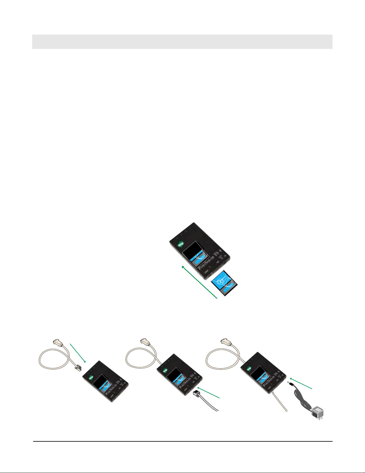
Install Radio
Place your country sticker on the back of the radio.
Slide radio into slot on top of Wireless device server BEFORE connecting
any cables or power supply. Only the radio shipped in the box will function
with the unit.
Note: Be sure that the grooves on the side of the radio are fit into the notched edges
— WARNING - If the power is connected when you plug the radio
Configuring Wireless
of the Wireless device server. Gently push radio into slot; fit should be snug.
into the device server, you will be required to reboot. It is not
recommended that the radio be removed while the power is
connected!
Using Ethernet
1. Connect serial cable, Ethernet cable, and power supply.
Chapter 4 Configuring Wireless 13
Page 14
2. Insert CD, the wizard will automatically pop up. Follow wizard either for
Microsoft Windows or Unix to configure the device. If you do not want
to use the wizard click Cancel and follow the remaining procedure to set
up the IP address and configure the device through the web interface.
3. Select Discover Digi Device (from the CD).
4. Select the wireless device and assign the IP address.
5. Click Set IP.
6. Enter the IP address, Subnet, and Gateway mask and click OK.
7. Select the device and click Configure to launch your browser.
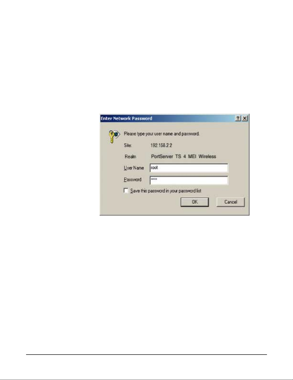
8. Enter the username root and password dbps and click OK.
14 Chapter 4 Configuring Wireless
Page 15
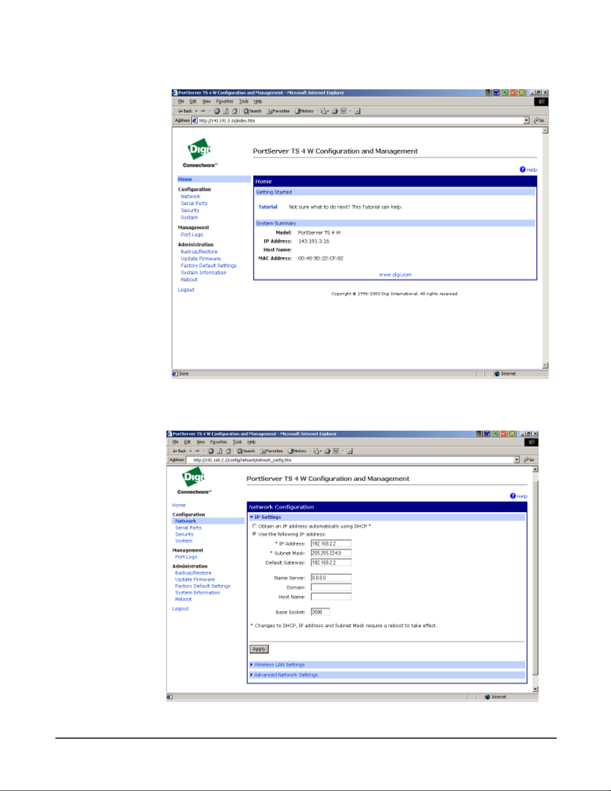
9. Click Network from the left navigation bar.
10.Enter parameters, click Apply to save then click Wireless LAN
Settings.
Chapter 4 Configuring Wireless 15
Page 16
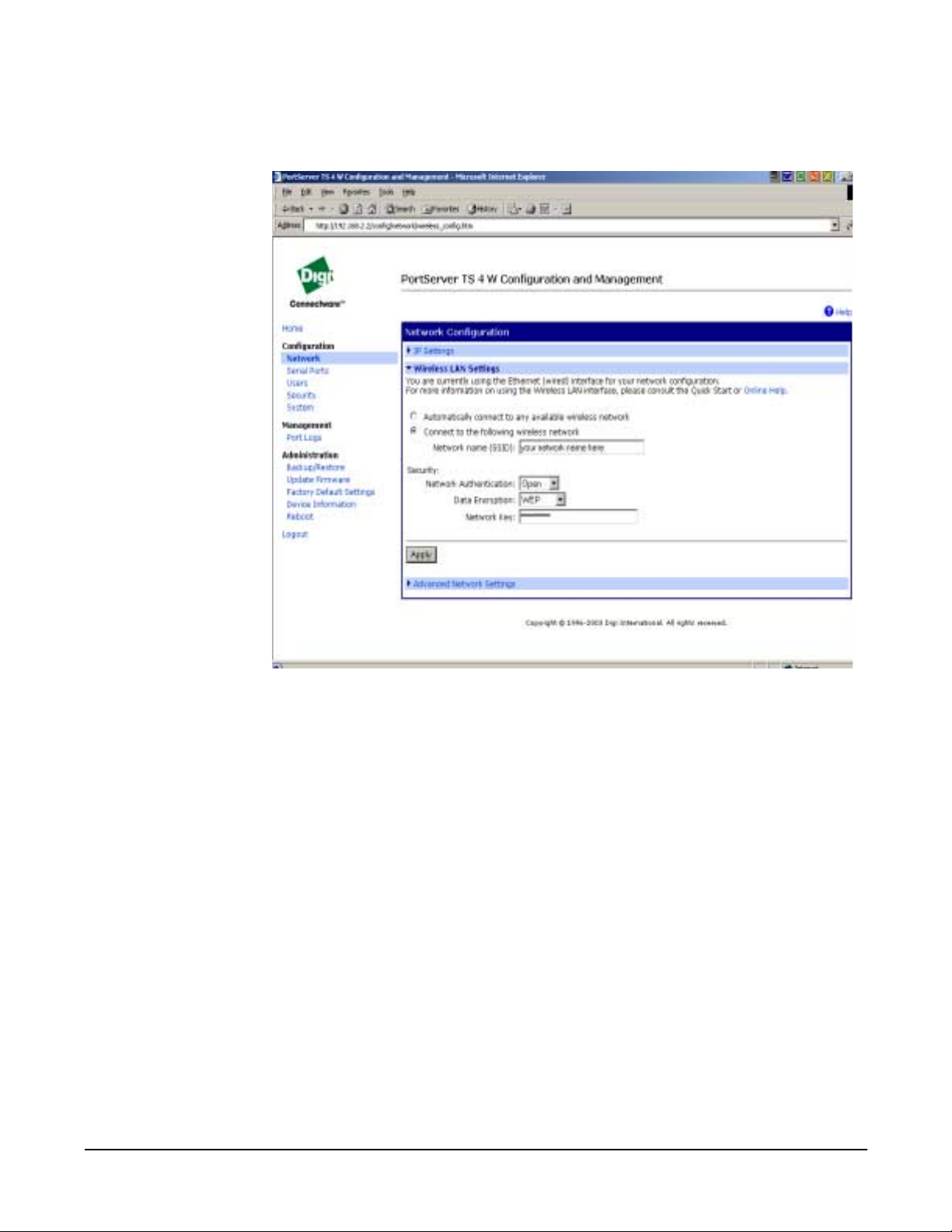
11.Enter the parameters and click Apply to save and Advanc ed N e twork
Settings for more settings.
16 Chapter 4 Configuring Wireless
Page 17
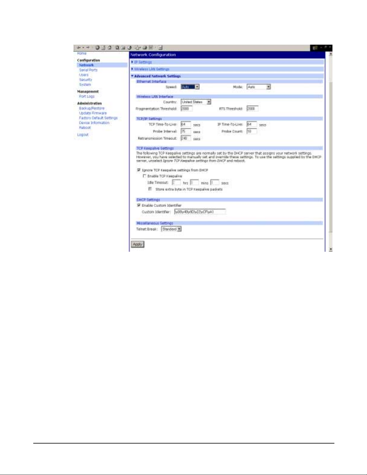
12.Enter parameters, click Apply to save.
13.Unplug the Ethernet cable from the device server, disconnect the
power, and power the unit up (reb oot).
Configuration is complete.
Chapter 4 Configuring Wireless 17
Page 18

18 Chapter 4 Configuring Wireless
Page 19

Chapter 5
Configuring the IP Address
Options for Configuring the IP Address and Mask
The device server IP address can be configured using the following
methods:
• With Digi Port Authority-Remote, a Digi utility on the Software and
Documentation CD.
• By updating the ARP table on a server and then pinging the Digi
device (called ARP-Ping, see "Configuring the IP Address Using
ARP-Ping" on page 20).
• From the command l ine using th e set config command ("Configur ing
the Ethernet Interface from the Command Line" on page 21
• Using a RARP server ("Configuring an IP Address using DHCP and
RARP" on page 22.)
• Using a DHCP server ("Configuring an IP Address using DHCP and
RARP" on page 22.)
The IP address and mask can also be changed using the web interface.
This method, however, does not work for the initial IP address
configuration.
.)
Device Support: Digi Port Authority-Remote and ARP-Ping for IP Address
Configuration
Not all Digi devices can use Digi Port Authority-Remote and ARP-Ping for
IP address configuration. To determine if you can use these features, find
the hardware label on your Digi device an d then use the table below t o
determine whether this feature is available:
Device Part Number Revision Required
Digi One IA RealPort 50000764-01 F or higher
Digi One RealPort 50000723-01 J or higher
PortServer TS 2 50000723-02 J or higher
PortServer TS 4 50000723-03 G or higher
Configuring the Ethernet Interface with Digi Port Authority-Remote
Use this section to configu re an initial IP add ress, subnet mask, and defau lt
gateway using Digi Por t Autho rit y-Re mote. Thi s proce dure cannot b e used
to change the IP address, but only to assign the initial IP address. It also
cannot be used if a DHCP server is active.
Starting Point
This procedure assumes the following:
• That your Digi device supports this feature. See "Device Support:
Digi Port Authori ty- Rem ote an d AR P- Pi n g for IP Address Configur ation" on page 19.
• That your Digi dev i ce is connected to the Ethernet network.
Chapter 5 Configuring the IP Address 19
Page 20

• That the Digi device has DHCP client turned on. This is the default
setting and it will be on unless it was turned off.
• That you do not have a DHCP server to serve IP ad dress. If you d o,
use the DHCP procedure. See "Configuring an IP Address using
DHCP and RARP" on page 22.
• That you have installed Digi Port Authority-Remote version 2.01.11
or later. For information on installing Digi Port Authority-Remote, see
the Digi Port Authority Remote Device Monitor Setup Guide, which
is on the Software and Documentation CD.
Procedure
1. Run Digi Port Authority-Remote.
2. If Digi Port Authority-Remote is not set for ADDP, choose ADDP as the
Discovery Protocol.
3. Click Discover.
A list of Digi devices appears. Systems with IP addresses of 0.0.0.0 need
IP addresses.
4. Select a device from the list and then click Configure.
5. Supply an IP address, subnet mask, and default gateway and then
choose OK.
Digi Port Authority-Remote configures the IP address, subnet mask, and
default gateway.
Configuring the IP Address Using ARP-Ping
Use this section to c onfigure an IP add ress by manually updating a
server’s ARP table and t hen pinging the Digi device.
Note: The ARP-Ping command assigns the IP address you designate but also
Starting Point
assigns default subnet mask and gateway addresses. It is necessary to
change the subnet mask and gateway addresses.
This procedure assumes the following:
• That your Digi device supports this feature. See "Device Support:
Digi Port Authori ty- Rem ote an d AR P- Pi n g for IP Address Configur ation" on page 19.
• That your Digi dev i ce is connected to the Ethernet network
Procedure
1. Record the MAC address of the Digi d evice. It ’s on the back of the unit.
2. Access a server on the same subnet as the Digi device.
3. Manually update the server’s ARP table using the Digi device’s MAC
address and the IP address you want assigned to the Digi device. The
following is an example of how this is done on a Windows NT 4.0
system:
arp -s 143.191.2.1 00-00-9d-22-23-60
20 Chapter 5 Configuring the IP Address
Page 21

4. Ping the Digi device using the IP address just assigned. The following is
an example:
ping 143.191.2.1
The ping will probably time out before there is a response from the Digi
device.
5. Wait a few seconds and then ping the Digi device again.
The Digi device r ep lie s to the ping, indicat ing that the IP addr ess ha s be en
configured.
Configuring the Ethernet Interface from the Command Line
This section discusses how to use the command line to configure an IP
address, mask, and default gateway for the device server’s Ethernet
interface.
Manual Configuration Procedure
1. To ensu re that the IP add r ess you configure is permanent, turn DHCP
off by entering the following command:
set config dhcp=off
2. To configure an IP address for the Ethernet interface, enter the
following command:
set config ip=ip-address
where ip-address is the IP address for the Ethernet interface
Example to Set IP Address
set config ip=191.143.2.154
3. To configure a subnet mask , enter the following command:
set config submask=mask
where mask is the subnet mask for this subnetwork
Example to Set Subnet Mask
set config submask=255.255.255.0
4. To configure a default gat eway, enter the following command:
set config gateway=ip-address
where ip-address is the IP address of the default gateway
Example to Set Gateway Mask
set config gateway=191.143.2.46
5. Reboot the Digi device at the pr ompt using the following command:
boot action=reset
Manual Configuration Example
In this example set config commands configure the Ethernet interface and
the boot command reboot the Digi device, which is required for the address
change to take affect.
set config ip=192.150.150.10 submask=255.255.255.0 dhcp=off
set config gateway=192.150.150.11
Chapter 5 Configuring the IP Address 21
Page 22

boot action=reset
Configuring an IP Address using DHCP and RARP
About DHCP and RARP
When the device server boots, it transmits a DHCP request and a RARP
request. This continues until an address is assigned.
Procedure
To use RARP or DHCP follow these steps:
1. Set up an entry for an address on a DHCP or RARP server. If you
intend to use RealPort, do the following:
• Reserve a perman ent IP address.
• Record the IP addr ess. You will need it when you configure the
RealPort driver.
2. Power on the device server.
The DHCP or RARP server assigns the device server an IP address.
22 Chapter 5 Configuring the IP Address
Page 23

Chapter 6
About RealPort
Setting Up RealPort
This section provides a brief introduction to RealPort.
What is RealPort?
RealPort is a feature that allows network-based host systems to use the
ports of the device server as though they were the host system’s own port s,
appearing and behaving as local ports to the network-based host.
RealPort Advantages
RealPort provides the following advantages:
• It expands the number of ports available to the host system.
• It enables device server ports to be treated as if they were directly
connected to the host, whi ch mean s they use al l st andar d opera ting
system interfaces that control baud rate, parity, stop bits, and flow
control.
• It enables host administrators to do most of the required
configuration on the host, the syst em with which th e administrator is
most familiar.
• It dramatically reduces host CPU overhead because multiple
terminal or printer sessions are multiplexed over the same TCP/IP
connection.
Configuring the RealPort Software
You must install and configure RealPort software on each host that will use
RealPort ports. See the RealPort documentation for more information.
1. From the CD, click Software. (If the wizard pops up, click cancel.)
The files are located in the drivers\windows\win2k\realport folder.
If you use the wizard, follow the steps in the pop-up after selecting the
Incoming scenario.
Chapter 6 Setting Up RealPort 23
Page 24

24 Chapter 6 Setting Up RealPort
Page 25
Chapter 7
Configuring the Serial Ports
Options for Configuring the Serial Ports
The device server serial ports can be configured using the following
methods:
• Through the web interface
• From the command l ine using th e set config command ("Configur ing
the Serial Port Settings from the Command Line" on page 26
serial ports can also be changed using the web interface or
command line.
Configuring the Serial Port Settings with the Web Interface
1. Log on to the device by ente ring the IP addr ess in the URL ad dress b ar
of your browser.
Note: This procedure can only be used if an IP address has been set.
2. Enter the username root and password dbps.
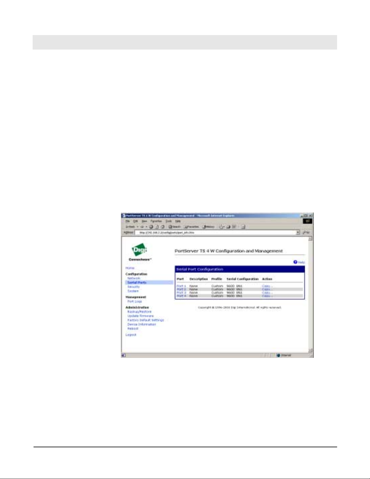
3. Click Serial Ports under Configuration.
.) The
4. Click the port number that you want to configure.
Chapter 7 Configuring the Serial Ports 25
Page 26
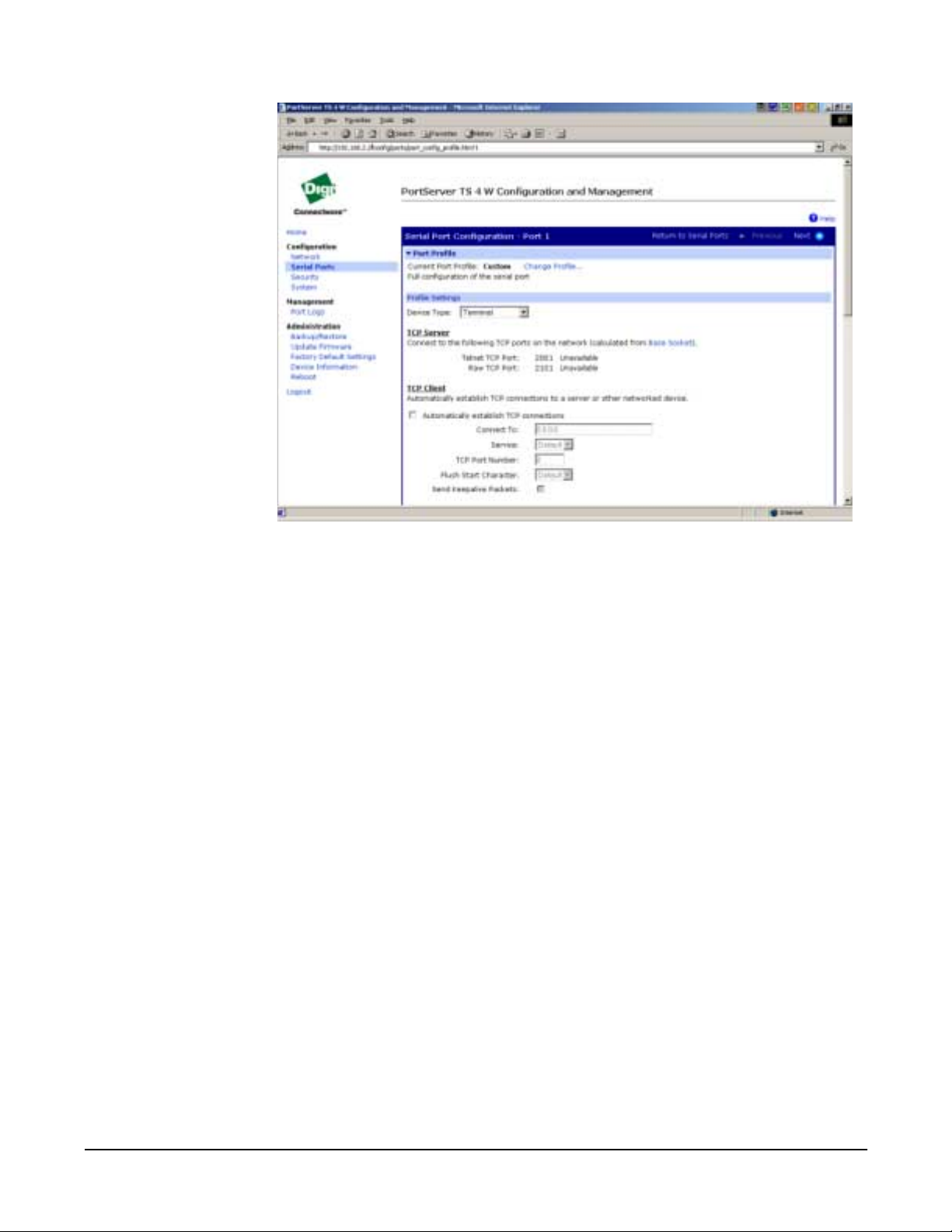
5. Click Change Profile and select a profile based on the device you have
connected to your port. Custom will expose all settings.
6. Click Apply to save the p r ofile. The interfa ce will determine any
additional settings and advise you what tab to click next.
7. A port profile or port options page will come up and ask for additional
parameters if needed. Enter the appropriate parameters and click
Apply.
Configuring the Serial Port Settings from the Command Line
Use the set ports, set line, and set flow commands from the Digi One/
PortServer TS 2/4 Command Reference to set the serial port settings.
26 Chapter 7 Configuring the Serial Ports
Page 27

Chapter 8
Configuring Inbound PPP Connections
Use this section to configure simple inbound PPP connections from the
command line. For informa tion on fine -tuning P PP connectio ns, see the se t
user command in the Digi One/PortServer TS Command Reference.
Note: CHAP authentication works between two Digi devices. CHAP will be
negotiated to PAP for all other connections
Procedure for Command Line
1. To configure the port for a modem, enter the following command:
set ports range=range dev=device
where range is the port or ports and device is one of the following:
• min for inbound only modem connections
• mio for bidirectional modem connections.
See the set ports command in the Digi One/PortServer TS Command
Reference for more information.
Example: set ports range=3 device=min
2. To conf igure flow control for the ports, en ter the following command:
set flow range=range flow-control=scheme
Configuring PPP
where range is the port or ports and flow-control=scheme is the flow control
required for this connection. Typically, for modem connections RTS and
CTS are on.
Example: set flow range=3 ixon=off ixoff=off rts=on cts=on
See the set flow command in the Digi One/PortServer TS Command
Reference for more information.
3. To configure the baud rate for this connection, enter the following
command:
set line range=range baud=bps
where range is the port or ports to config ure and bps is the line speed in
bits-per-second. Typically, you can set this to 115000 bps for modem
connections.
Example set line range=3 baud=115000
4. To create an inbound PPP user, enter the following command:
set user name=name protocol=ppp netservice=on
defaultaccess=netservice
where name is a name to assign the P PP user
Example:
set user name=pppin protocol=ppp netservice=on
defaultaccess=netservice
5. To configure an IP address for the remote PPP user, enter the following
command:
Chapter 8 Configuring PPP 27
Page 28

set user name=name ipaddr=ip-address
where
• name is the user’s name
• ip-address is one of the following: (a) A standard IP address in
dotted decimal format. (b) 0.0.0.0, which means the remote user will
supply the IP address (c) ippool, which means that the user will be
assigned an IP a ddr e ss fr om an IP ad dr ess pool. See the set ippool
command in the Digi One/PortServer TS Command Reference.
Example:
set user name=pppin ipaddr=ippool
6. If you used the IP address pool option in the previous step, specify the
following subnetwork mask using the following command: (a mask of
255.255.255.255 is required)
set user ipmask=255.255.255.255
7. To configure an IP address for the local end of the PPP connection,
enter the following command:
set user name=name localipaddr=ip-address
where name is the user’s name and ip-address is the IP address to assign
to the local end of the PPP connecti on . Th i s a ddr e ss m ust be u ni qu e. That
is, no other user can be assigned this address and it cannot be the IP
address for the Ethernet interface.
Example: set user name=pppin localipadr=199.1.1.2
Configuring Inbound PPP Connections: Example
This example shows a very simple PPP inbound configuration. Here are
some points on this configuration:
• The port is set up for inbound connections (dev=min).
• RTS and CTS are used fo r flow control.
• The baud rate has been set to 115000 bps.
• The user has been configured to use an IP address pool
set ports range=3 device=min
set flow range=3 ixon=off ixoff=off rts=on cts=on
set line range=3 baud=115000
set user name=pppin protocol=ppp netservice=on
defaultaccess=netservice
set user name=pppin ipaddr=ippool
set user name=pppin localipadr=199.1.1.2
Configuring Outbound PPP Connections: Command Line
This section describes how to conf ig ure out bo und PP P conn ections. U se i t
to configure outbound only connections or to configure the outbound
portion of bidirectional connections.
Note: CHAP authentication works between two Digi devices. CHAP will be
28 Chapter 8 Configuring PPP
negotiated to PAP for all other connections
Page 29

Procedure
1. To configure the port for a modem, enter the following command:
set ports range=range dev=device
where range is the port or ports and device is one of the following:
• mout for outbound only modem connections
• mio for bidirectional modem connections.
See the set ports command in the Digi One/PortServer TS Command
Reference for more information.
Example: set ports range=3 device=mout
2. To conf igure flow control for the ports, en ter the following command:
set flow range=range flow-control=scheme
where range is the port or ports and flow-control=scheme is the flow control
required for this connection. Typically, for modem connections RTS and
CTS are on.
Example: set flow range=3 ixon=off ixoff=off rts=on cts=on
See the set flow command in the Digi One/PortServer TS Command
Reference for more information.
3. To configure baud rate for this connection to the modem, enter the
following command:
set line range=range baud=bps
where range is the port or ports to config ure and bps is the line speed in
bits-per-second. Typically, you can set this to 115000 bps for modem
connections.
Example: set line range=3 baud=115000
4. If you do not want to use the Digi-supplied dialer script (genmdm) and
login script (loginscript), which work for mo st applications, use the set
script command to create your own scripts.
See the set script command in the Digi One/PortServer TS Command
Reference for more information.
5. If you do not want to use the Dig i-suppl ied outb ound device (gendi aler),
which works for most applications, enter the fo llowing command:
set device name=name ports=ports dialer=name
where
• name=name is the name for this device
• ports=ports are the ports to associate with this device
• dialer=name i s the name of a dia ler script, either the Digi-supplied
script or a user-created one
6. To create a PPP user, enter the following command:
set user name=name protocol=ppp
where name is the name of the PPP user
Example: set user name=pppout protocol=ppp
Chapter 8 Configuring PPP 29
Page 30

7. To configure this user for outbound connections, enter the following
command:
set user name=name outgoing=on device=device
where device is either the Digi-supplied device or the o utbound device
created earlier in this procedur e
Example:
set user name=pppout outgoing=on device=gendialer
8. To configure an IP address for the local end of the PPP connection,
enter the following command:
set user name=name localipaddr=ip-address
where name is the u ser’s name and ip-address is one of the following:
• 0.0.0.0. , which means that the user will request an IP address from
the remote server.
• A specific IP address, which means that the Digi device will attempt
to use this IP address. The remote server must agree to this
request.
Example:
set user name=pppout localipadr=0.0.0.0
9. To configure a telephone number to dial to reach the outbound user,
enter the following command:
set user name=name n1=telephone-number
where name is the u ser’s name and telephone-number is the number to
dial to reach the user. You can enter this number as digits only, with
dashes (-) separating digits, or with commas.
Example: set user name=pppout n1=4452624
Sample
The following sample shows a very simple outbound PPP configuration.
Here are some points on this configuration:
• The port is set up for outbound connections (dev=mout).
• Flow control is set to Hardware.
• Default device and scripts are used
set ports range=3 device=mout
set flow range=3 ixon=off ixoff=off rts=on cts=on
set line range=3 baud=115000
set user name=pppout protocol=ppp
set user name=pppout dialout=on outgoing=on device=gendialer
set user name=pppout localipadr=0.0.0.0
set user name=pppout n1=4452624
30 Chapter 8 Configuring PPP
Page 31

Filters for PPP Connections
Use the following table for additional configurations.
set user
Field
passpacket
keepup
bringup
logpacket
Description Example
Causes a packet to be
passed or blocked
Causes the idleti meout timer
to be reset and a connec tio n
maintained.
Causes the Digi device to
establish a connection.
Causes the Digi device to
send a message to the log
file
Filter causes incoming packets from an IP address
to be accepted and packets from all other IP
addresses to be blocked
Filter that causes the con nec tio n to be maintained
as long as there is any packet traffic except RIP
packets.
Filter that causes an out goi ng c onn ec tio n to b e in itiated whenever a p acke t sp ecify ing a p articu lar IP
address is handled
Filter that notifies the lo g any ti me a n ICMP p a ck et
is handled
Chapter 8 Configuring PPP 31
Page 32

32 Chapter 8 Configuring PPP
Page 33

Chapter 9
Modem Emulation
Modem Emulation (Digi One TS and PortServer TS 2/4 MEI only)
Modem emulation enables a system administrator to configure a
networked Digi device server to act as a modem. The Digi device server
emulates modem responses to a serial device and seamlessly sends and
receives data over an Ethernet network instead of a PSTN (Public
Switched Telephone Network). The advantage for a user is the ability to
retain legacy software applications without modification and use a less
expensive Ethernet network in place of public telephone lines.
To use a Digi device server for modem emulation, do the following:
• use a cable with the correct wiring pinouts (see "Modem Emulation
Cable Signals" on page 34)
• configure the serial ports and device type with the Web Interface
Note: Before AT commands are accepted, DSR must go high on the Digi device
server.
Common User Scenarios
The Digi device server in modem emulation mode allows for the easy
replacement of modems in almost any environment where there is a LAN
or WAN.
User Scenario-Diagram A
Workstation
Ethernet
S
T
E
N
O
I
G
I
Serial cable
Digi One TS
#1
D
Server
192.168.25.5
In Diagram A, the Digi One TS replac es a modem connec ted to a
workstation running an application. The Digi One TS allows for the use of
software applications without modification by responding to all the AT
commands configured in the workstation application. The Digi One TS
connects to the IP Address of the server when an
ATDT ipaddress:port (ATDT 192.168.25.5:50001)
command is issued. Once the remote device establishes the TCP
connection, a CONNECT message is sent to the serial port and only then
does the Digi device server switch from AT command mode to data mode.
Using the modem escape sequence or dropping DTR on either side
terminates the connection. A DISCONNECT message will be sent to the
Chapter 9 Modem Emulation 33
Page 34

application if the remote side closes the TCP connection.
User Scenario-Diagram B
Workstation
S
T
E
N
O
I
G
I
Serial cable
Digi One TS
#1
D
Ethernet
Workstation
S
T
E
N
O
I
G
I
D
#2
Digi One TS
192.168.25.30
Serial cable
In Diagram B, two Digi device servers will replace modems on both sides of
the connection. The initiation of the connection occurs with either of the
Digi device servers. If both ends are Digi device servers, the TCP listening
port number is 50001 for port 1. An example of the connection command is
ATDT 192.168.25.30:50001. Upon establishing a successful TCP
connection, a CONNECT message is sent to the serial port and only then
does the Digi device server switch from AT command mode to data mode.
After the CONNECT is received, the transmission of data begins. U sing
the modem escape sequence or dropping DTR on either side terminates
the connection.
Modem emulation has the ability to communicate to an infinite nu mber of
other devices.
Modem Emulation Cable Signals
Use the following signal assignments to make a cable connecting the Digi
device server to a serial device.
Note: DSR and DTR on the serial device side are connected to the DSR signal of
the Digi device server.
Serial Device Digi Device Server
CTS (in) RTS (out)
RTS (out) CTS (in)
DSR (in) DSR (in)
DTR (out)
DCD (in) DTR (out)
TX (out) RX (in)
RX (in) TX (out)
GND GND
34 Chapter 9 Modem Emulation
Page 35

Originating, Answering, and Disconnecting Calls
In the following table, an application requests a TCP session with the Digi
device server. The table displays the responses of the Digi device server
and application as they negotiate a TCP connection.
Application AT Com-
mand
AT&F OK.
ATDT ipaddress:TCPport#
<P>+++<P> OK
ATH NO CARRIER response sent
Digi Device Server Response Notes
AT command request to restore defaults to factory settings-Digi device server responds OK.
Receives request to start a
TCP session. CONNECT
115200.
Request to start TCP session with IP address and TCP
port number of the Digi de vice serv er-Digi devi ce server
starts a TCP session
Escape sequence is sent <P> is Pause in seconds with
“+++” being the escape seq uen ce in ASCII c haracters Digi device server switches from AT command to data
mode
Disconnect AT command is sent-Digi device server
responds with NO CARRIER
In the following table, the Digi device server receives a request for a
connection.
AT Command Digi Device Server Res pon se Notes
RING The Digi device server sends a Call Notification
Manual (ATA) or Auto Answer (ATS0=n) response-the
ATA (or ATS0=n) CONNECT 115200
NO CARRIER
Digi device server sends a CONNECT message when
the TCP session is started
The Digi device serve r sends a N O CARRIER me ssage
when the remote disconnects
Originating Calls
To send data to a Digi device server, enter the following information for
your application replacing the telephone number with the Digi device
server’s IP address and TCP port number. Enter the following command:
ATDT ipaddress:tcp_port#
an example is ATDT 146.135.13.5:50001
Answering Calls
The Digi device server listens on a pre-defined TCP port to receive data.
When the Digi device server receives a call notification (RING) through a
serial port to begin a TCP connection, it needs to reply with an ATA or a
pre-configured Auto-Answer to answer the call.
Note: The TCP ports assigned to the serial ports are as follows:
Serial port 1 listens on TCP port 50001
Serial port 2 listens on TCP port 50002
Serial port 3 listens on TCP port 50003
Serial port 4 listens on TCP port 50004
Disconnecting Calls
The TCP connection d isconn ects by either dropping the DTR si gn al o n the
serial port or sending the escape se quence <P>+++<P> to the Digi device
Chapter 9 Modem Emulation 35
Page 36

server. <P> represents a one se cond pause.
Disconnecting Calls-Digi Device Server
The Digi device server sends a NO CARRIER response to the serial port
when the network connection is dropped.
36 Chapter 9 Modem Emulation
Page 37

Modem Emulation AT Command Set
AT
Command
ATA
ATD<IP>:
<TCP
PORT>
Function
Answer command: The Digi Device Server will go off hook and answer a
TCP connection request.
This command directs the Digi Device Server to go on-line, dial according to
the IP address entered as follow 191.1.2.3:12 and attempt to establish a
TCP connection. If no dial string is supplied, the Digi Device Server will
respond no dial tone.
Note: If the ATD command is issued before the S1 register has cleared, the
modem will respond with the NO CARRIER result code.
Dial Modifiers. The valid dial string parameters are described below. Punctuation characters may be used for clarity with parentheses, hyphen, and
spaces being ignored.
Result
Code
Command echo. The Digi Device Server enables or disables the echo of
ATEn
characters to the DTE according to the parameter supplied. The parameter
value, if valid, is written to S14 bit 1.
E0 : Disables command echo
OK n=0 or 1
ERROR
Otherwise
E1 : Enables command echo
Disconnect (Hang up) command
ATH
This command initiates a hang up sequence.
H0 : Disconnect the TCP session if the modem is currently on line.
H1 : If on-hook, the Digi Device Server will go off-hook and enter command
OK n=0 or 1
ERROR
Otherwise
mode.
Chapter 9 Modem Emulation 37
Page 38

AT
Command
Identification command
I0 reports product code. Example: Digi Device server
I1 reports 255
I2 reports “OK”
I3 reports “OK”
ATIn
ATLn Accepted but ignored.
ATMn Accepted but ignored.
ATNn Accepted but ignored.
ATOn
ATP Accepted but ignored.
ATQn
ATSn
ATT Acc ep ted but ign or ed..
ATVn
ATWn Accepted but ignored.
I4 reports DIGI DS_TS
I5 reports “OK”
I6 reports “OK”
I7 reports “OK”
I8 reports “ERROR”
I9 reports “ERROR”
Return to On-Line Data Mode.
This command determines how the modem will enter the on-line data mode.
If the modem is in the on-line command mode, the modem enters the online data mode. If the modem is in the off-line command mode (no connection), ERROR is reported.
O0Enters on-line data mode. Handling is determined by the Call Establishment task. Generally, if a connection exists, this command connects the
DTE back to the remote modem after an escape (+++).
O1Same as above
Quiet Results Codes Control command.
The command enables or disables the sending of the result codes to the
DTE according to the parameter supplied. The parameter value, if valid, is
written to S14 bit 2.
Q0 Enables result code to the DTE (Default).
Q1 Disables result code to the DTE
Read/Write S- Register.
n Establishes S-register n as the last register accessed
n=v Sets S-Register n to the value v.
n? Reports the value of S-Register n.
Result Code Form. This command selects the sending of short-form or longform codes to the DTE. The parameter, if valid, is written to S14 bit 3.
V0 Enables short-form (terse) result codes. Line feed is not issues before a
short-form result.
V1 Enables long-form (verbose) results codes (Default).
Function
Result
Code
OK n=0 or 9
ERROR
Otherwise
OK n=0 or 3
ERROR
Otherwise
OK n=0 or 3
ERROR
Otherwise
OK n=0 or 1
ERROR
Otherwise
OKn = 0 or 1 and
a connection
exists.
ERROR
Otherwise or if
not connected.
OK
OK n=0 or 1
ERROR
Otherwise
OK
OK n=0 or 1
ERROR
Otherwise
OK n=0 to 3
ERROR
Otherwise
38 Chapter 9 Modem Emulation
Page 39

AT
Command
Function
ATXn A ccep ted but ign ored.
ATYn A ccep ted but ign ored.
ATZn Accepted but ignored. (Soft Reset and restore Profile).
DCD Option. The Digi Device Server controls the DCD output in accordance with the parameter supplied. The parameter value, if valid is written
AT&Cn
to S21 bit 5.
&C0 DCD remains ON at all times.
&C1 DCD follows the state of the connection
DTR Option. This command interprets the ON to OFF transition of the DTR
signal from the DTE in accordance with the parameter supplied. The parameter value, if valid, is written to S21 bits 3 and 4. Also see S25.
&D0 -DTR is ignored (assumed ON). Allows operation with DTEs which
do not provide DSR.
AT&Dn
&D1DTR drop is interpreted by the modem as if the asynchronous escape
sequence had been entered. The modem returns to asynchronous command state without disconnecting.
&D2DTR drop causes the modem to hang up. Auto-answer is inhibited.
(Default.)
&D3DTR drop causes the modem to perform a soft reset as if the Z command were received. The &Y setting determines which profile is loaded.
Restore Factory Configuration (Profile)
The Device Server loads the factory default configuration (profile). The fac-
AT&Fn
tory defaults are identified for each command and in the S-Register descriptions. A configuration (profile) consists of a subset of S-Registers.
&F0Restore factory configuration 0.
&F1Restore factory configuration 1.
AT&Jn Accepted but ignored.
AT&Gn Accepted but ignored.
AT&Jn Accepted but ignored.
Flow control. This command defines the DTE/DCE flow control mechanism.
The parameter value, if valid, is written to S39 bits 0, 1, and 2.
&K0 Disable s flow control
AT&Kn
&K3 Enables RTS/CTS flow control (Default)
&K4 Enables XON/XOFF flow control
&K5 Enables transparent XON/XOFF flow control
&K6 Enables both RTS/CTS and XON/XOFF flow control.
AT&Ln Accepted but ignored.
Result
Code
OK n=0 to 3
ERROR
Otherwise
OK n=0 or 1
ERROR
Otherwise
OK n=0 or 1
ERROR
Otherwise
OK n=0 or 1
ERROR
Otherwise
OK n=0 to 3
ERROR
Otherwise
OK n=0 or 1
ERROR
Otherwise
OK n=0 or 1
ERROR
Otherwise
OK n=0 or 1
ERROR
Otherwise
OK n=0 or 1
ERROR Other-
wise
OK n=0,3,4,5,or 6
ERROR
Otherwise
OK n=0, 1, 2
ERROR
Otherwise
Chapter 9 Modem Emulation 39
Page 40

AT
Command
Function
AT&Mn Accepted but ignored.
AT&Pn Accepted but ignored.
AT&Qn Accepted but ignored.
RTS/CTS Option
This selects how the Digi Device Server controls CTS. CTS is modified if
hardware flow control is selected (see &K command). The parameter value,
if valid, is written to S21 bit2.
&R0CTS reflects the ability of the modem to transmit data. For example,
AT&Rn
CTS will drop during retrains. In sync mode, CTS tracks the state of RTS;
the RTS-to-CTS delay is defined by S26. In async mode, CTS is normally
ON and will turn OFF only if required by flow control.
&R1CTS forced on (default). In sync mode, CTS is always ON (RTS transitions are ignored). tracks the state of RTS. In async mode, CTS is normally
ON and will turn OFF only if required by flow control.
&R2CTS follows RTS.
DSR Override
This command selects how the modem will control DSR. The parameter
AT&Sn
value, if valid, is written to S21 bit 6.
&S0DSR will remain ON at all times. (Default.)
&S1DSR will become active after answer tone has been detected and inac-
tive after the carrier has been lost.
AT&Tn Acc ep ted but ign or ed.
AT&V
Display Current Configuration and Stored Profiles
There is no NVRAM support currently.
AT&Vn Accepted but ignored.
AT&V6 Display current IP settings of the Device Server
AT&Wn Accepted but ignored.
AT&Xn Accepted but ignored.
AT&Yn Accepted but ignored.
AT&Zn
&Zn=x - Store Telephone Number.
Currently not supported
AT\An Accepted but ignor ed.
Result
Code
OK n=0, 1, 2
ERROR
Otherwise
OK n=0, 1, 2
ERROR
Otherwise
OK n=0 to 8
ERROR
Otherwise
OK n=0 or 1
ERROR
Otherwise
OK n=0 or 1
ERROR
Otherwise
OK n= 0
ERROR
Otherwise
OK
OK n=0 to 5
ERROR
Otherwise
OK
OK n=0 or 1
ERROR
Otherwise
OK n=0 or 1
ERROR
Otherwise
OK n=0 or 1
ERROR Otherwise
OK n=0 or 3
ERROR
Otherwise
OK n=0 to 3
ERROR
Otherwise
40 Chapter 9 Modem Emulation
Page 41

AT
Command
AT\Gn Accepted but ignored.
AT\Kn Accepted but ignor ed.
Operating Mode
This command controls the preferred error correcting mode to be negotiated
in a subsequent data connection.
\N0 Selects normal speed buffered mode
AT\Nn
AT\Vn Accepted but ignor ed.
AT+MS Accepted but ignored.
AT+MI Accepted but ign ored.
AT%Cn Accepted but ignored.
\N1 Serial interface selected - Selects direct mode
\N2 Accepted but ignored.
\N3 Accepted but ignored.
\N4 Accepted but ignored.
\N5 Accepted but ignored.
Function
Result
Code
OK n=0 or 1
ERROR
Otherwise
OK n=0 to 5
ERROR
Otherwise
OK n=0 to 5
ERROR
Otherwise
OK n=0 or 1
ERROR
Otherwise
OK
OK
OK n=0 to 3
ERROR
Otherwise
Chapter 9 Modem Emulation 41
Page 42

S-Registers
Register Function Range Units Saved Default
Rings to Auto-Answer
S0
S1
S2
S3
S4
S5
S6 Accepted but ignored. 2-255 s * 2
S7 Accepted but ignored. 1-255 s * 50
S8 Accepted but ignored. 0-255 s * 2
S9 Accepted but ignored. 1-255 0.1 s * 6
S10 Accepted but ignored. 1-255 0.1 s * 14
S11 Accepted but ignored. 50-255 0.001 s * 95
S12
Sets the number of rings required before the
Digi Device Server automatically answers a
call. Setting this register to Zero disables autoanswer mode.
Ring Counter
S1 is incremented each time the modem
detects a ring signal on the telephone line. S1
is cleared if no rings occur over an eight second interval.
Escape Character
S2 holds the decimal value of the ASCII char-
acter used as the escape character. The
default value corresponds to an ASCII ’+’. A
value over 127 disables the escape process,
i.e., no escape character will be recognized.
Carriage Return Character
Sets the command line and result code termi-
nator character. Pertains to asynchronous
operation only.
Line Feed Character
Sets the character recognized as a line feed.
Pertains to asynchronous operation only. The
Line Feed control character is output after the
Carriage Return control character if verbose
result codes are used.
Backspace Character
Sets the character recognized as a backspace.
Pertains to asynchronous operation only. The
modem will not recognize the Backspace character if it is set to a value that is greater than 32
ASCII. This character can be used to edit a
command line. When the echo command is
enabled, the modem echoes back to the local
DTE the Backspace character, an ASCII space
character and a second Backspace character;
this means a total of three characters are transmitted each time the modem processes the
Backspace character.
Escape Prompt Delay
Defines the maximum period, in fiftieths of a
second, allowed between receipt of the last
character of the three escape character
sequence from the DTE and sending of the OK
result code to the DTE. If any characters are
detected during this time, the OK will not be
sent. Note that sending of the OK result code
does not affect entry into command mode.
0-255 Rings * 0
0-255 Rings 0
0-255 ASCII * 43
0-127 ASCII 13
0-127 ASCII 10
0-32 ASCII 8
0-255 0.02 s * 50
42 Chapter 9 Modem Emulation
Page 43

Register Function Range Units Saved Default
S13 Reserved - - -
General Bit Mapped Options Status
Indicates the status of command options.
Default:138 (8Ah) (10001010b)
Bit 0This bit is ignored.
Bit 1Command echo (En)
0 =Disabled (E0)
1 =Enabled (E1) (Default.)
Bit 2Quiet mode (Qn)
0 =Send result codes (Q0) (Default.)
1 =Do not send result codes (Q1)
S14
S15 Reserved - - S16 Accepted but ignored. - - 0
S17 Reserved - - S18 Accepted but ignored. 0-255 s * 0
S19 Accepted but ignored. - - 0
S20 Accepted but ignored. 0-255 - * 0
Bit 3Result codes (Vn)
0 =Numeric (V0)
1 =Verbose (V1) (Default.)
Bit 4Reserved
Bit 5Tone (T)/Pulse (P)
0 =Tone (T) (Default.)
1 =Pulse (P)
Bit 6Reserved
Bit 7Originate/Answer
0 =Answer
1 =Originate (Default.)
*
138
(8Ah)
Chapter 9 Modem Emulation 43
Page 44

Register Function Range Units Saved Default
General Bit Mapped Options Status
Indicates the status of command options.
Default:52 (34h) (00110100b)
Bit 0Set by &Jn command but ignored otherwise.
0 =&J0 (Default.)
1 =&J1
Bit 1Reserved
Bit 2CTS behavior (&Rn)
0 =CTS tracks RTS (&R0)
1 =CTS always on (&R1) (Default.)
Bits 3-4DTR behavior (&Dn)
S21
S22 Accepted but ignored. - - *
0 =&D0 selected
1 =&D1 selected
2 =&D2 selected (Default.)
3 =&D3 selected
Bit 5RLSD (DCD) behavior (&Cn)
0 =&C0 selected
1 =&C1 selected (Default.)
Bit 6DSR behavior (&Sn)
0 =&S0 selected (Default.)
1 =&S1 selected
Bit 7Long space disconnect (Yn)
0 =Y0 (Default.)
1 =Y1
- - * 52 (34h)
117
(75h)
44 Chapter 9 Modem Emulation
Page 45

Register Function Range Units Saved Default
General Bit Mapped Options Status
Indicates the status of command options.
Default:62 (3Dh) (00111110b)
Bit 0Grant RDL
0 =RDL not allowed (&T5) (Default.)
1 =RDL allowed (&T4)
Bits 1-3DTE Rate
0 =0 - 300 bps
1 =600 bps
2 =1200 bps
S23
S24 Accepted but ignored. 0-255 s * 0
S25
S26
S27 General Bit Mapped Options Status - - * 73 (49h)
S28 Accepted but ignored. - - * 0
S29 Accepted but ig nored. 0-255 10 ms 70
S30 Accepted but ig nored. 0-255 10 s 0
S31 Accepted but ignored. - - *
S32 XON Character 0-255 ASCII 17 (11h)
S33 XOFF Character 0-255 ASCII 19 (13h)
S34 S35 Reserved - - S36 Accepted but ignored. - - * 7
3 =2400 bps
4 =4800 bps
5 =9600 bps
6 =19200 bps
7 =38400 bps or higher (Default.)
Bits 4-5Assumed DTE parity
0 =even
1 =not used
2 =odd
3 =none (Default.)
Bits 6-7not action applied
Delay to DTR Off
Sets the length of time that the modem will
ignore DTR for taking the action specified by
&Dn. Its units are seconds for synchronous
modes and one hundredths of a second for
other modes
RTS-to-CTS Delay
Sets the time delay, in hundredths of a second,
before the modem turns CTS ON after detecting an OFF-to-ON transition on RTS when &R0
is commanded. Pertains to synchronous operation only.
0-255
0-255 0.01 s 1
s or
0.01 s
*
5
62
(3Dh)
194
(C2h)
Chapter 9 Modem Emulation 45
Page 46

Register Function Range Units Saved Default
General Bit Mapped Options Status
Telnet support for modem emulation.
Default:0
Bit 0-1 Send TCP transmit data timer
0 = 100ms
1 = 200 ms
2 = 300 ms
3 = 500 ms
Bits 2-3 Service TCP transmit data watermark
0 = 256
1 = 512
2 =768
S37
3 =1024
Bits 4-5 Se rvice TCP receive data watermark
0 = 256
1 = 512
2 =768
3 =1024
Bits 6-7 Telnet support (RFC 2217)
0 = Disabled
1 = Receive Telnet support enabled
2 = Transmit Telnet support enabled
3 = Receive and Transmit Telnet support
enabled
--*0
S38 Accepted but ignored. 0-255 s 20
Flow Control Bit Mapped Options Status
Default:3 (00000011b)
Bits 0-2Status of command options
0 =No flow control
S39
S40 Accepted but ignored. - - *
S41 Accepted but ignored. - - *
S42 - S45 Reserved - - -
S46 Accepted but ignored. - - * 138
S48 Accepted but ignored. - - * 7
S82 Accepted but ignored. - -
S86 Accepted but ignored. 0-255 - -
3 =RTS/CTS (&K3) (Default.)
4 =XON/XOFF (&K4)
5 =Transparent XON (&K5)
6 =Both methods (&K6)
Bits 3-7Reserved
--*3
104
(68h)
195
(C3h)
128(40h)
46 Chapter 9 Modem Emulation
Page 47

Register Function Range Units Saved Default
10
S91 Accepted but ignored. 0-15 dBm
S92 Accepted but ignored. 0-15 dBm
S95 Accepted but ignored. - - * 0
* Register value may be stored in one of two user profiles with the &W command.
(Country
dependent)
10
(Country
dependent)
Result Codes
Short Long Form Short Long Form Short Long Form
0OK 13
1CONNECT
2RING
3 N O CARRIER
4 ERROR
5
6 N O DIALTONE
7BUSY
8 NO ANSWER
9
10
11
12
CONNECT
1200
CONNECT
0600
CONNECT
2400
CONNECT
4800
CONNECT
9600
14
15
16
17
18
19
20
59
61
62
63
64
CONNECT
7200
CONNECT
12000
CONNECT
14400
CONNECT
19200
CONNECT
38400
CONNECT
57600
CONNECT
115200
CONNECT
230400
CONNECT
16800
CONNECT
21600
CONNECT
24000
CONNECT
26400
CONNECT
28800
84
91
165
166
167
168
169
170
171
172
173
174
CONNECT
33600
CONNECT
31200
CONNECT
32000
CONNECT
34000
CONNECT
36000
CONNECT
38000
CONNECT
40000
CONNECT
42000
CONNECT
44000
CONNECT
46000
CONNECT
48000
CONNECT
50000
Chapter 9 Modem Emulation 47
Page 48

48 Chapter 9 Modem Emulation
Page 49

Chapter 10
Configuring Autoconnection
About Autoconnection
The autoconnection feature allows you to configure a user to access the
device server and then be automatically connected to a host on the LAN.
You can implement autoconnection in the following ways:
• By port where all port users are automatically connected to the
same host. The device server is completely transparent to them.
• By user where a user is required to log on and may be required to
supply a password, but once the user is authenti cated, an automat ic
connection to a host is made.
Configuring a Port for Autoconnection: Web Interface
This section describes ho w to con fi gure a por t for au toco nn ection from the
web interface.
1. Access the web interface by entering the device server IP address in a
browser’s URL window.
2. Log on to the device server as root. The default password is dbps.
3. Select Serial Ports under Configuration.
4. Click Change Profile under Port Profile.
5. Click the prof ile based on the device connected to your port.Use the
online help for more information.
Note: TCP Sockets is the Autoconnection profile.
6. To return to the main Ports menu, choose Ports from the Menu again.
Commands for Configuring Autoconnection by Port or by User
See the complete list of commands in the Digi One/PortServer TS
Command Reference. The commands needed for auto connection either b y
port or by user will be under the following commands in the Command
Reference on your Software and Documentation CD.
• set ports
• set user
Configuring a User for Autoconnection: Web Interface
1. Access the web interface by entering the device server IP address in a
browser’s URL window.
2. Log on to the device server as root. The default password is dbps.
3. Click Users from the menu.
4. Choose New User.
5. Enter a username and then click Next.
6. Select the “Terminal/Terminal Emul ation” user profile and click Next
Chapter 10 Configuring Autoconnection 49
Page 50

7. Check Automatically connect to a ... Be sure to specify the following:
• Hostname or IP address that will be the destination
• Service
• Destination TCP port number, which determines the type of connec-
tion for this user (such as 23 for Telnet)
8. Click Next and Verify the settings.
9. Click Finish to save settings.
Configuring TCP Socket Communication
TCP socket communication enables serial devices to communicate with
each other over an Ethernet network as though they were connected by a
serial cable.
This section describes how to use the web interface to configure this Digi
device for the following:
• Inbound connections, that is, connections that are initiated by the
device on th e other side of the network
• Outbound connection, that is, connections that are initiated by the
device connected to the serial port
Procedure for Configuring Inbound and Outbound Socket Communication
1. Access the web interface by entering the device server IP address in a
browser’s URL window.
2. Log on to the device server as root. The default password is dbps.
3. Click Serial Ports.
4. Click the port number you wish to configure.
5. Click Change Profile.
6. Select TCP Sockets and click Apply.
7. Enter the parameters for the appropriate connection. Use the context
sensitive Help for additional information.
Configuring UDP Multicast
The Digi One and PortServer TS devices are devices capable of UDP
multicast. UDP m ult icast is u sed to se nd se rial d at a ove r an Ethe rnet cabl e
to one or many hosts at the same time. UDP is a connectionl ess protocol,
meaning UDP does not need a protocol, but is sending data without any
form of acknowledgement or error correction. Up to 64 devices can receive
a UDP multicast at one time. Both the transmitting and receiving devices
must be configured properly for UDP multicast to work.
This section describes how to use the web interface to configure this Digi
device for the following:
• Inbound connections, that is, connections that are initiated by the
device on th e other side of the network
• Outbound connection, that is, connections that are initiated by the
device connected to the serial port
50 Chapter 10 Configuring Autoconnection
Page 51

Procedure for Configuring Inbound or Outbound Socket Communication
1. Access the web interface by entering the device server IP address in a
browser’s URL window.
2. Log on to the Digi On e/PortServer TS as root. The default p assword is
dbps.
3. Click Serial Ports.
4. Click the port number you want to configure.
5. Click Change Profile and select UDP Socket
Note: The serial parameters for two connecting devices must match meaning if one
device is set for 9600 bps, the other device must be set for the same rate.
6. Fill in the requested information and click Apply to save the settings.
7. Repeat these steps until you ha ve adde d the necessa ry dest inations.
Use the context sensitive Help for additional information.
Chapter 10 Configuring Autoconnection 51
Page 52

52 Chapter 10 Configuring Autoconnection
Page 53

Chapter 11
Configuring Static Routes
This section describes how to configure device server for static route s .
Related Information
See the set route command in the Digi One/PortServer TS Command
Reference.
Procedure
To configure a static route over a PPP link, enter the following command:
set route net=addr mask=mask metric=hops wanname=interface
gateway=gateway
where
• addr is either the IP address of a system to be reached over this
• mask is the mask to use for interpreting the IP address.
• metric is the number of hop to the destination
• interface is either ether if this route is over the Ethernet interface or
Configuring IP Routing
route or the network address of the subnet that is to be reached on
this route
the name of a user if the route is over a PPP link
• gateway is the IP address of the device that is the next hop to the
destination
Example: Route Using the Ethernet Interface
In this example, a route to a subn et is created over the Ethernet i nterface.
Key features include the following:
• The address on the net field is a subnetwork address, not the IP
address of a specific device
• The wannane=ether, indicating that this route is over the Ethernet
interface
• The metric field indicates that packets to this subnet will pass
through two routers
• The gateway field indi cates that all packets using this route are to be
forwarded to the device at IP address 191.21.21.2.
set route net=199.21.33.0 mask=255.255.255.0 metric=2
wannname=ether gateway=199.21.21.2
Example: Route Using a PPP Link
In this example, a route to a subnet is created over a PP P interface. Key
features include the following:
• The address on the net field is IP addres s of a spe cific d evice, n ot a
subnetwork address
• The WAN name is the name of a PPP user.
Chapter 11 Configuring IP Routing 53
Page 54

• The metric field indicates that packets to this subnet will pass
through two routers
• The gateway field indi cates that all packets using this route are to be
forwarded to the device at IP address 191.21.21.2.
set route net=199.21.33.44 mask=255.255.255.255 metric=2
wannname=ppp1 gateway=199.21.21.2
Configuring Dynamic Routes Using RIP
This section describes how to configure the device server for dynamic
routing.
Related Information
See the set forwar ding com mand in the Digi One/PortServer TS Command
Reference.
Starting Point
This procedure assumes that you have signed on as root and have or will
configure modems, mode m scri p ts, devices, and filters for routes that use
serial lines.
Procedure
1. Configure the links over which routed packets and RIP updates will be
sent.
• To enable routing over the LAN to which device server is attached,
no routing-specific configuration is required.
• To enable routing over PPP links be sure to use the netrouting field
on the set user command to configur e ho w devi ce server handles
RIP updates. You can configure the link so that device server does
any of the following with RIP updates:
—Both sends and receives them (netrouting=both)
—Sends them only (netrouting=send)
—Receives them only (netrouting=receive)
—Neither sends nor receives them (netrouting=off)
2. Configure t he device server fo r dynamic routing wi th a set forwarding
command that specifies state=active.
Example: Dynamic Routes
In this example, which shows only thos e commands and command fields
pertinent to routing, device server is configured for dynamic routing using
RIP. But to prevent RIP updates from being sent across the PPP link, the
set user command that defines the link specifies netrouting=off.
54 Chapter 11 Configuring IP Routing
Page 55

set forwarding state=active poisonreverse=on splithorizon=on
set user name=link1...netrouting=off
Configuring Proxy ARP
This section describes how to config ur e devi ce serve r for Pro xy ARP.
Related Information
See the set forwar ding com mand in the Digi One/PortServer TS Command
Reference.
Starting Point
This procedure assumes that you have signed on as root and have or will
configure modems, mode m scri p ts, devices, and filters for routes that use
serial lines.
192.150.75.0
Router
187.100.46.9
Digi Device
PPP
Procedure
1. Configure the links over which packets will be routed using a set user
command. This command must specify (on the ipaddr field) a specific
IP address for the remote system using the Proxy ARP service.
2. Configure device server for Proxy ARP by supplying a set forwarding
command that specifies the following:
• state=passive
• proxyarp=on
Example
In this example, device server provides Proxy ARP services to a remote
host.
187.155.24.0
Digi Device
PPP
187.155.24.11
set user name=link1...ipaddr=187.155.24.11
set forwarding state=passive proxyarp=on
Chapter 11 Configuring IP Routing 55
Page 56

56 Chapter 11 Configuring IP Routing
Page 57

Chapter 12
Configuring Security Features
Controlling Access to the Configuration
Controlling access of device server restricts access to the configuration by
defining the following types of users:
• The root user, who has unlimited access to device server com-
mands. He or she can view any conf ig uration table and cha ng e any
configuration parameter. The root is identified by the user name
root and must supply a password to be authenti cat ed. The default
root password is dbps. You should change this password immediately.
• Regular users, who have much more restricted access to device
server commands. Regular users can view some configuration
tables and can chan ge some configuration parameters related to
their own sessions and p asswords. Se e the Digi One/PortServer TS
Command Reference for information on the limitations placed on
regular users for e ach command.
Controlling Access to Inbound Ports
This section describes methods of controlling access to inbound serial
ports. An inbound port is one defined on the dev field of the set ports
command for one of the followin g device types:
• term (used to define terminal connections)
• min (used to define incoming modem connections)
• mio (used to define bi-directional modem connections)
• hdial, hio (used to define computer connections)
Default Access Restrictions
The default configuration for inbound ports is that a login and password are
required to access them.
Options for Removing Access Restriction
The login and password requirement for inbound ports can be changed by
configuring
• The port so that it does not require a login and password. In this
case, no one is required to supply a login or password.
• Specific users so that they do not require a password. In this case,
some users do not supply passwords and others are required.
Procedure for Changing a Port’s Access Requirements
To configure a port so that no one has to login or specify a password,
supply a set logins command that specifies the following:
set logins range=range login=off passwd=off
Chapter 12 Configuring Security Features 57
Page 58

Example:
set logins range=1-2 login=off passwd=off
Procedure for Changing a User’s Access Requirements
To configure a user so that he or she does not have to specify a password
when accessing an inbound port, supply a se t user comma nd that speci fies
the following:
set user name=name password=off
where name is a name to identify the user
Example:
set user name=user1 password=off
Controlling Access to Outbound Ports
This section describes methods for controlling access to outbound serial
ports. An outbound port is one defined on the dev field of the set ports
command for one of the followin g device types:
• prn (used to define printer connections)
• mout (used to define outbound modem connections
• mio (used to define bi-directional modem connections)
• host (used to define host connections)
• ia
Default Access
The default for outbound ports is unlimited access.
Restricting Access to Outbound Ports
Use the set auth command to restrict access to outbound ports. See the
description of the set auth command in the Digi One/PortServer TS
Command Reference for more information.
CHAP Authentication for PPP Users
CHAP authentication can be used to restrict PP P u ser acce ss to ou tbo un d
ports. For more information on CHAP configuration, see the set user
command in the device server Command Reference.
Controlling Access to the Command Line
This section describes how to restrict access to the device server
command line.
Autoconnection
The autoconnection feature allows you to configure a user to access the
device server but then be automatically connected to a host on the LAN.
You can implement autoconnection in the following ways:
• By port where all port users are automatically connected to the
same host. The device server is completely transparent to them.
58 Chapter 12 Configuring Security Features
Page 59

• By user where a user is required to login and may be required to
For information on configuring autoconnection, see "Configuring
Autoconnection" on pa ge 49.
Method 2: Menus
Menus select destination systems without having to access the device
server command line. For information on configuring menus, see the
description of the set menu command in the Digi One/PortServer TS
Command Reference.
Issuing User Passwords
This section discusses how to issue user passwords.
Related Information
See the newpass and set user commands in the Digi One/Port Ser ve r TS
Command Reference.
Starting Point
This procedure assumes that you have signed on as root and already
configured the user to whom you will be issuing a password.
supply a password, but once the user is authenti cated, an automat ic
connection to a host is made.
The Advanced tab under User allows you to set Escape characters for
Connect, Telnet, Rlogin, and Kill as well as an SSH Public Key. Click Apply
to save the settings.
Procedure
1. Issue a newpass command that identifies the user (on the name field)
to whom this password will be issued.
2. When the system prompts you for a new password, type in the password and then press Enter.
3. When the system prompts you to enter the new p assword again, type it
in and then press Enter.
Configuring SSH Version 2 for Secure Communication
This section discusses how to configure a user for SSH version 2
encryption.
This feature is only available for the following devices.
Device
Digi One TS 50000771-01A or higher
PortServer TS 2 MEI 50000771-02A or higher
PortServer TS 4 MEI &
Wireless
Required
Hardware
50000771-03A or higher
Required
Firmware
82000747a or higher
Chapter 12 Configuring Security Features 59
Page 60

Password Protection
To configure simple password authentication for an SSH user, no
SSH-specific configuration is required. Simply configure a user by entering
the following commands:
set user name=name password=on
newpass name=name
where name is a user name
Example:
set user name=ssh-user1
newpass name=ssh-user1
Using a Public Key
To enable public key authentication and to associate a public key with a
user, enter the following command:
set user name=name loadkey=host:key
where
• name is the name of a user
• host is either an IP address or DNS name of a host running TFTP
that holds
• key is the name of a file that contains the DSA public key. If your
host’s implementation requires a complete path to the file, specify
the path here as well.
Example:
set user name=secure loadkey=143.191.2.34:ssh-file
Making Reverse SSH Connections to Ports
The convention used to identify a port for a reverse SSH connection to a
Digi device is to us e 2 50 0 + th e po r t nu m ber. See the examples that f ol low
for more information.
Example: Reverse SSH Connection to Port 1
ssh 192.1.2.3 2501
Example: Reverse SSH Connection to Port 4
ssh 192.1.2.3 2504
Controlling Access to Services
This section describes ho w to disab l e ser vi ces, such as Telnet and Rlo gi n,
for inbound users, which means that they cannot access the Digi device
using those ser vices. This feature allows you to turn off individual services
or to specify a security level, which means that all services not included in
that level are turned off.
Services that Can Be Turned Off
The following services can be turned off.
• HTTP
60 Chapter 12 Configuring Security Features
Page 61

• RealPort
• Reverse TCP
• Reverse Telnet
• Remote login
• Remote shell
• SNMP
• SSH
• Telnet
Service Levels
These are the secure access levels:
• Secure, which means that SSH is the only service available to
inbound users
• High, which means that SSH, HTTP, SNMP, and RealPort services
are available to inbound users
• Normal, which means all services are available
• Custom, which means you can select services to turn off.
The default service level is normal, whic h means that all services are
available.
Procedure
Use this topic for information on using the web interface to turn services off.
1. Access the device server from a web browser by entering the Digi
device’s IP address in the URL window.
2. Log on as root. The default passwor d is dbps.
3. Click Security under Configuration.
4. Select the Secure Access tab an d select t he security level you want or
choose Custom to select the spec ific servic es you want to turn off. Use
the context sensitive help for information on configuration fields.
Chapter 12 Configuring Security Features 61
Page 62

62 Chapter 12 Configuring Security Features
Page 63

Chapter 13
Configuring Modbus
Modbus is a protocol that defines how devices in an industrial automation
(IA) environment communicate. It specifies that a controlling unit, called a
master, manages one or more units, called slaves. The protocol specifies
that only the master may in itiate commu nication. Slaves may only respon d.
The protocol defines the structure of Modbus messages, determines how
the master requests information from the slave or specifies an action for
the slave to take, defines how the slave is to respond, specifies addressing
conventions, and deals with many of the other details required for
communication to occur. Modbus defines two encoding schemes, Modbus
ASCII and Modbus RTU. Each Modbus device uses one or the other.
Designed to function over a serial commu nication cab le, Modbus ha s been
extended in rec ent years to function over an Ethernet network using
Modbus/TCP, which defines a method of encapsulating Modbus ASCII or
Modbus RTU messages in IP packets for transport over the network.
The extermely flexible Digi implementation includes support for Modbus
ASCII, Modbus RTU, Modbus/TCP, and two other methods of transport
over a network, TCP socket and UDP socket communication. The
implementation enables multiple netw ork-based masters to concurrently
initiate communica tion w ith se r ial -b ase d sl a ves u si ng an y of th e su pp or ted
network prot ocols.
Configuring the Digi Device for IA
(Industrial Automation)
Modbus Configuration Procedure
Use the setia command from the See the Digi One/PortServer TS
Command Reference for information.
• Configure the serial port for the serial communication parameters
(baud rate, dat a bi t s, p ari ty and st op bit s) requi red by th e conne cted
IA device.
• Choose Modbus ASCII or Modbus RTU as the serial port protocol,
depending on the requir emen ts of the IA device connected to the
port.
• If you configure the port for a slave, you do not have to configure a
network-based master. Communication with the master just works.
(If the master is connected to a serial port, it must be configured,
however.)
• If you configure a port for a master and the slaves are located on the
network, TCP sockets, UDP sockets, and Modbus/TCP are all supported. Use the p r otocol required by the master.
Configuring the User-Defined Protocol
Digi One\PortServer TS 2/4 MEI devices support what Digi calls the “user-
defined” protocol, which is any IA serial-port protocol with the following
attributes:
Chapter 13 Configuring the Digi Device for IA (Industrial Automation) 63
Page 64

• All message packets are bounded by fixed header and trailer
strings.
• Each protocol request is followed by a single response.
Modbus Configuration Procedure
Use the setia command from the See the Digi One/PortServer TS
Command Reference for information.
• Configure the serial port for serial communication parameters (baud
rate, data bits, parity and stop bits) required by the connected IA
device.
• Choose User-defin ed as the serial-port protocol.
• If you configure the port for a slave, you do not have to configure a
network-based master. Communication with the master just works.
(If the master is connected to a serial port, it must be configured,
however.)
• If you configure a port for a master and the slaves are located on the
network, TCP sockets and UDP sockets are supported options.
64 Chapter 13 Configuring the Digi Device for IA (Industrial Automation)
Page 65

Chapter 14
About the Domain Name System
This section discusses key concepts of the domain name system.
Purpose of DNS
The domain name system maps domain names to information associated
with these names, such as IP addresses.
DNS Components
DNS components include:
• A distributed database consisting of domain names and associated
information
• A hierarchical system of domain name servers that maintain the
database and use it to respond to requests for information about a
particular domain name, such as its IP address
• Domain name resolvers that
— Accept requests from users
— Satisfy information requests by building and submitting properly
formulated queries to on e or mo r e na me ser ver s or by re tri e ving
information from a local host file
Configuring DNS
— Return information to users
— Cache information for future use
Types of Name Servers
There are two types of name servers in the domain name system:
• Local servers maintain information for resources within a local zone.
It is up to individual network administrators to determine the scope
of a local zone.
• Root servers maintain information in higher-level domains than do
local servers.
Typically, when a user requires information about a domain name, the
resolver queries a local server. If local servers cannot provide the
information, root servers are queried next.
Naming Conventions
Each node in the domain name system has a globally unique domain name
that consists of its own name, which is called a label, and the labels of all
superior nodes.
DNS Name Example
Here is an example of a domain name. Note that labels are separated by
periods:
mn07.amalgamated.com
In this example, mn07 is part of the higher-level domain called
Chapter 14 Configuring DNS 65
Page 66

amalgamated.com.
Configuration Procedures
Procedure for Using a Name Server
To configure a DNS server, enter the following command:
set config domain=domain myname=name dns=ip-address
where
• domain is the domain in which the device ser ver will reside
• name is a DNS name for device server
• ip-address is the IP address of a name server
Example:
set config domain=digi.com myname=poe dns=204.221.1.4
Procedure for Using a Host File
Use this section to configure the ho st table, which maps IP addresses to
host names.
Enter the following command
set host name=name ip=ip-address
where
• name is the name the host
• ip-address is the IP address of the host
Example
In this example, three IP address-to-name mappings are configured
set host name=poe ip=204.221.110.200
set host name=gary ip=204.221.110.202
set host name=toni ip=204.221.110.203
66 Chapter 14 Configuring DNS
Page 67

Chapter 15
About SNMP and the Device Server Agent
This section introduces SNMP and network management in TCP/IP
networks and it describes the device server agent. It discusses the
following:
• Network management components
• SNMP agent
• SNMP traps
• MIB support of the device server agent
• Support traps of the device server agent
Network Management Components
The TCP/IP network management architecture contains the following
components:
• Managed nodes such as host systems, routers, terminal and com-
munications servers (such as device server) and other network
devices
• One or more network managers (also called net work managemen t
stations), which are the points from which the network is man aged
Configuring SNMP
• Agents that resi de on managed nodes and retrieve management
information and communicate this information to network managers
• The network management protocol, SNMP, which governs the
exchange of inf ormation between the nodes and statio ns
• Management information, which is t he database of information
about managed objects. This database is called the management
information base (MIB).
SNMP Management Agent
Each managed node contains at least one agent—a compo nent that
responds to requests from the network manager—that retrieves network
management information from its node a nd notifies the ma nager when
significant events occur.
SNMP Traps
A mechanism defin ed by SNMP is called a trap, which is a r eport or “alarm”
from a managed node to an SNMP manager that a significant event has
occurred.
MIB Support
The agent supports the following MIBs:
• Read-write for MIB II (RFC 12 13), which is an Internet-standard
MIB, consisting of managed ob jects from the systems, inte rfaces, IP,
ICMP, TCP, UDP, transmission, and SNMP group
Chapter 15 Configuring SNMP 67
Page 68

• Read-write for the character-stream devices using SMIv2 MIB (RFC
1658)
• Read-write for the RS-232-like hardware devices MIB (RFC 1659)
• Read-write for the device server IP Network Control Protocol of the
Point-to-Point Protocol MIB (RFC 1473)
Message Support
The SNMP agent supports the Set, Get, GetNext, and Trap messages as
defined in RFC 1157. These messages are used as follows:
• Set, which means set the value of a specific object from one of the
supported MIBs
• Get, which means retrieve the value of a specific object form one of
the supported MIBs
• GetNext, which means retrieve the value of the next object in the
MIB
• Trap, which means send traps to the manager when a particular
type of significant event occurs
Supported Traps
The agent can send traps when any of the following occur:
• Cold starts (device server initializes)
• Authentication failures
• Login attempts
Configuration Procedure: Web Interface
1. Access the web interface by entering the device server IP address in a
browser’s URL window.
2. Log on to the device server as root.
Note: The default password is dbps, which should be changed. See the newpass
command in the Digi One/PortServer TS Command Reference for information
on changing passwords.
3. Click SNMP under System from the menu.
4. Fill in the configuration fields and click Apply to save settings.
68 Chapter 15 Configuring SNMP
Page 69

Chapter 16
About Configuring Users
Although it is not required, the device server is often configured to
accommodate the requirements of particular users. Typical configurable
user attributes include the following:
• Whether the user is required to supply a password
• Autoconnection attributes, such as the system to which the user
• The interface the device presents the user, such as a menu or
• Whether the user has access to o utbound ports
Note: For information on configuring PPP users, see "Configuring PPP" on page 27.
Configuration Methods
You ca n configure users in the following ways:
• With the web interface.
• With the set us er command. See the set user co mmand in the Digi
Configuring Users
should be automatically connected at login
command line
One/PortServer TS Command Reference.
Common User Features
This section discusses common user-related features. For a complete list,
see the set user command in the Digi One/PortServer TS Command
Reference.
Feature Description set user Field
Automatically connects the user to the host specified on the autohost
field using the service (TCP port) defined on the autoport or
autoconnect
Default
access type
Menu access
Port access
PPP Defines PPP-related parameters for the user.
Routing
updates
autoservice fields.
Autoconnection can also be implemented by port instead of by user.
This feature is configurable from the web interface.
Defines the type of access the user is restricted to. Menu, command
line, autoconnect, and outgoing and netservice are the types.
This feature is configurable from the web interface.
Defines the menu that is to be presented to a user with menu access.
This feature is configurable from the web interface.
Defines the number of outbound ports a user connected over the LAN
can access at one time.
This feature is not configurable from the web interface.
Defines whether RIP routing updates are forwarded over the link to this
user.
autoconnect
autohost
autoport
autoservice
defaultaccess
menu
maxsessions
There ar e too
many fields to list
here. See the set
user command
for more
information.
netrouting
Chapter 16 Configuring Users 69
Page 70

Configuring a User: Web Interface
Use this section to c onfigure users with from the web interface.
1. Access the web interface by entering the device server IP address in a
browser’s URL window.
2. Log on to the device server as root. The default password is dbps.
3. Click Users under Configuration.
4. Click New User.
5. Enter the user name and password (password is optional).
6. Select the profile for user.
7. Enter appropriate parameters, click Next, and verify settings.
Note: If the user profile is Custom there are no parmeters to set. Click Finish if user
name is correct.
8. Click Finish to save settings.
Note: To edit a user go to the Users page and click on the user name you wish to
edit, enter the parameters and click Apply.
The Advanced tab under User allows you to set Escape characters for
Connect, Telnet, Rlogin, and Kill as well as an SSH Public Key. Click Apply
to save the settings.
Commands for Configuring a User
Use the commands listed below as well as find specific examples and
complete parameters from the Digi One/PortServer TS Command
Reference.
• set user (name=)
• newpass to assign a password
• default access=menu to config ure a user for a menu
• autoconnect to automatically connect a user
• remove to remove a user from the user table
70 Chapter 16 Configuring Users
Page 71

Chapter 17
Managing the OS and Configuration
Upgrading the Firmware
This section describes how to upgrade the firmware, which can be done
from the web interface using HTTP or FTP.
HTTP or TFTP Upgrade Procedure
If your hardware is okay, make sure you are running the latest firmware
version available. Check the Digi Support site for the latest firmware and/or
POST updates for your device:
http://ftp.digi.com/support/firmware
1. Download a copy of the firmware file.
2. Access the Digi device server’s web interface by entering the Digi
device server’s IP address in a browser’s URL window and log on (User
Name root, Password dbps).
3. Choose Update Firmware under Administration from the main menu.
4. Browse to the location on your system where the firmware has been
saved, select the correct file, and click Update.
Do not leave
your
browser until
you are
prompted to
reboot.
5. Reboot the device when prompted.
6. Access the Digi device server’s web interface and verif y on the
Information Page that the Firmware version has been successfully
updated.
Command Line
If you want to use the command li ne to upgrade firmware, use the boot
command. See the Digi One/PortServer TS Command Reference for more
information.
Copying the Configuration to and from a Remote Host
This section discusses copying the configuration to a remote host and from
a remote host, which means you can configure th e Digi device remot ely by
entering commands in a text file and then copying the file to the Digi
device.
When To Use Remote Configuration
Typically, you use remote configuration when you have several device
servers with simila r configura tions and w ant to ke ep a mas ter configu ration
on a remote host, from which you can easily create variations for
downloading to individual device servers.
Rules for Editing a Configuration file
Here are some rules for editing a configuration file on a remote host:
• Edit the file with any text editor.
• Each line of the file must start with a set command, such as set user
or set line. In other words, do not let comm ands wrap to the ne xt line
if your editor supports this function.
Chapter 17 Managing the OS and Configuration 71
Page 72

HTTP Procedure
1. Access the web interface by entering the device server IP address in a
browser’s URL window.
2. Log on to the device server as root. The default password is dbps.
3. From the main menu, choose Adm in > HTTP Cp C on f.
4. To copy a file from the host you are on do the following:
— Choose Browse, select the file, and then choose Submit.
— Follow the prompts to complete this procedure.
5. To copy a file to
a remote host, do the following:
— Right click on the Download current config link.
— Choose Save Target as
— Specify a file name and then choose Save.
6. Follow the prompts to complete this task.
TFTP Procedure
1. Ensure that TFTP is running on the remote host.
2. Access the web interface by entering the device server IP address in a
browser’s URL window.
3. Log on to the device server as root. The default password is dbps.
4. From the main menu, choose Admin > TFTP CpConf.
5. Choose either Copy configuration to a TFTP server or Copy configuration from a TFTP server.
6. Specify an IP address and a file name and then choose Submit.
7. Follow the prompts to complete this task.
Command Line
If you want to use th e command li ne to copy the configura tion to and f rom a
remote host, u se the cpconf co mmand. See the Digi One/PortServer TS
Command Reference for more information.
Resetting Device Server Configuration to Defaults
Use this topic to reset the device server conf i gur a tion to defaults.
Note: This procedure causes the device server to lose all configuration changes. If
Procedure
you have a complex configuration, contact Digi before performing for information on saving your configuration. See "Reference and Certifications" on page
79 for information.
1. Use a pen, the point of a paper clip, or some other device to press the
recessed button on the front panel.
2. While holdi ng down the button, power on the device server.
3. When the 1-5-1 LED pattern is displayed, release the button.
The device boots up.
72 Chapter 17 Managing the OS and Configuration
Page 73

Commands for Resetting the Configuration to Defaults
Use the revert comman d to reset the co nfiguration to factory defau lts or the
latest version stored in NVR AM. See the Digi One/PortServer TS
Command Reference for complete information.
Note: You can also use the range field on this command to define a range of ports
with the serial, port, line, flow, keys, and login options.
Chapter 17 Managing the OS and Configuration 73
Page 74

74 Chapter 17 Managing the OS and Configuration
Page 75

Chapter 18
Configuring Power Over the Serial Ports
Serial Power Feature
The Serial Power feature available for the Digi One TS, PortServer TS 2
MEI, and PortServer TS 4 MEI allows the Digi device to power a serial
device (power out) or use a serial device to power the Digi device (power
in). The advantage of this feature is to eliminate an external power supply.
Power out is available on all ports through Ring Indicator (RI) or Data
Terminal Ready (DTR). Power in is available only through RI and only on
port one (1). The Seri al Power fe ature is ac tive on a spec ific port whe n that
port is configured for RS 232 operation.
• The power out budget equals one (1) watt (the total amount of
power available). The available power can be divided in any c ombination between the ports but the following rules must be observed:
— RI = 5 volts @ up to 200 mA (max)
— DTR = 9 volts @ up to 100 mA (max)
— You may use DTR or RI as the source of power (power out) on
any port but you may not use bot h DTR a nd RI on the same po rt.
• Pinout information
— RI is pin 1
— DTR is pin 9
Configuring RI Power
RI Power In
Ring Indicator (RI) power in accepts power into the Digi device server only
on port one. Power in is availabl e using the RI pin . The Digi device r equires
power in the range of 9-30 VDC @ 525mA (max). Ports 2, 3, and 4 can still
supply power to a serial device through the RI or DTR pins for each port.
When using power in through the RI, the external power supplies (both
powered Ethernet and the barrel connector power supply) are inoperative.
Altpin will not work for RI power in.
1. Open the device unit enclosure and move the black jumper to the
• RI signaling is lost when the pin is used for power
following settings:
P-6 jumper on pins 1 and 2
Note: When the jumper is placed correctly for
power in, the jumper will set on the pins
closest to the edge of the board. The left
arrow indicates the open pin and the right
arrow is pointing to the jumper.
Chapter 18 Configuring Power Over the Serial Ports 75
Page 76

2. Close the device unit enclosure.
RI Power Out
Ring Indicator (RI) power out is available on all ports. The total power
budget for this featu re is one (1 ) watt not to exceed 5 volt s @ up to 200mA
on any single port. The following procedure assumes the unit will only be
used for RI power out.
1. Set the port D IP switches to the fo l low in g pl ace s : swi tch 1 and 3 are up
and 2 and 4 are do wn (see "Serial Power Table" on page 77 for
illustration).
2. Enable the RI power through the web interface.
3. Connect power supply w ith the barrel -connect or power suppl y provided
with the device or use powered Ethernet.
Note: If the unit will be used with RI power in (port 1 only), set the jumper to the
Configuring DTR Power
Power Out
Data Terminal Ready (DTR) power out is the factory default on the Digi
device server. Total power budget for this feature is one watt not to exceed
9 volts @ up to 100mA to any single port.
following setting:
P-6 jumper on pins 1and 2
and do not use an external power source. Port 1 cannot be used for both
power in and power out.
1. Set the port DIP switches to EIA 232 (switch 1 is up, 2,3, and 4 are
down) to enable DTR power.
2. Open the port and set DTR high.
Note Here are the pins to
verify the jumper
position. The default
position has the
jumper on the two pins
furthest from the edge.
DO NOT MOVE THE
JUMPER FROM THE
DEFAULT UNLESS
USING RI POWER IN.
If you are havi ng trouble with your unit after using the Power over port
feature, you may have tripped the circuit breaker in the unit. You can
identify this by the RI or DTR signal indicators found in the System
Information under Administration on the main menu in the web interface.
Click the port number using serial power. (Remember serial power out is
unavailable if the MEI settings are not 232.)
Under serial power will be a message if the breaker is tripped. Follow the
76 Chapter 18 Configuring Power Over the Serial Ports
Page 77

Serial Power Table
instructions to reset.
From the command line use the two examples below for additional
information.
display circuitbreaker
Display the status of the circuit breaker
set configuration circuitbreaker=reset
Reset the circuit breaker
Note: set configuration print will also give the status of the circuitbreaker state.
Use this table for summary information for a serial power setup.
.
Quick Summary
Table for Setup of
Serial Power
Switch Settings
DTR Power RI Power
OUT OUT IN
DTR setting DTR ON DTR OFF DTR OFF
1*, 2, 3, 4
Ports Allowed 1, 2, 3, 4
P-6 jumper on pins
Jumper Pin Settings
(Factory Default)
Power Budget
9v @ up to 100mA
one watt
2 & 3
*unless port 1 is used
for power in
P-6 jumper on pins
2 & 3
(Factory Default)
5v @ up to 200 mA
one watt
P-6 jumper on pins
9 -30 v @ up to
525mA (max)
1
1 & 2
Chapter 18 Configuring Power Over the Serial Ports 77
Page 78

78 Chapter 18 Configuring Power Over the Serial Ports
Page 79

Chapter 19
Interpreting the LEDs
LEDs
Reference and Certifications
LED Color St ate Indicates
On Power detected
Waiting for an IP
address
Starting t he TFTP
process
Configuration returned
to factory defaults
Signal strength relates
to brightn ess or
dimness of the light
Physical network
detected
No physical network
detected
Power
Radio
Signal
Strength
Status
(Link)
ACT Yellow
Green
(labeled PWR)
Yellow Varying brightness
Green
Steady blinking
Blinking 1-1-1 Starting the EOS
Blinking 1-3-1
Blinking 1-5-1
Off No power detected
On
Off
On Bad initialization
Off Ready
Blinking Network activity
LED Diagnostics
LED Activity Indication
1-1-1 pattern Starting the EOS.
1-3-1 pattern TFTP boot process started.
1-5-1 pattern
9-1-1 pattern
Steady blinking Device seeking an IP address from DHCP server.
Solid
Tells you that configuration has been return to the factory
configuration. See "Managing the OS and Configuration"
on page 71.
Contact Tech Support for help.
1-952-912-3444 or outside the U.S. (+011) 952-912-3444
On Digi One RealPort and PortServer TS 2/4 devices, this
means the boot completed sucessfully.
Chapter 19 Reference and Certifications 79
Page 80

Device Server EIA 232/422/485 Switch Settings
Function
EIA-232 Up Down Down Down
EIA-422/485 Full-duplex Down Up Down If up, termination.
EIA-485 half-duplex Down Down Up
RJ-45 Pinouts
RJ-45
Pin
1 RI TxD- TxD-
EIA-232
1 2 3 4
EIA-422/485
Full-Duplex
Switch Settings
If down,
no termination
EIA-485 Half-
Duplex
2 DSR RxD- RxD3RTS RTS+ NA
4 GND GND GND
5 TxD TxD+ TxD+
6 RxD RxD+ RxD+
7SG SG SG
8CTS CTS+ NA
9DTR RTS- NA
10 DCD CTS- NA
WARNING: To prevent electric shock, do not remove the cover of this
module while unit is powered up. There are no user-serviceable parts
inside. Refer servicing to qualified personnel.
CAUTION: This unit has two power inputs. For total isolation from electrical
shock and energy hazard, disconnect both power inputs. The device is
intended to be mounted in an indoor only type system.
80 Chapter 19 Reference and Certifications
Page 81

Standard Models Specifications
2-contact barrel
connector
Power Requirements
(Standard Models)
+9 to +30 VDC 525 mA (max)
external power supply
Environmental
Certifications
Ambient
temperature
Relative
humidity
Altitude
Length
Width
Height
Weight
0 to 50° Celsius
32 to 131° Fahrenheit
5% to 90% non-condensing
0 to 12,000 feet
0 to 3,658 meters
Mechanical
13.33 centimeters
5.25 inches
8.25 centimeters
3.25 inches
3.842 centimeters
1.306 inches
.227 Kilos
8 ounces
FCC Part 15 Class A
Radio Frequency Interference (RFI) (FCC 15.105)
This equipment has been tested and found to comply with the limits for
Class A digital devic es pursuant to Part 15 of the FCC Rules. These limits
are designed to provide r easonab le pro tection a gainst har mful in terfere nce
in a residential environment. This equipment generates, uses, and can
radiate radio freq uency e nergy, and if not inst all ed and u sed in accor dance
with the instruction manual, may cause harmful interference to radio
communications. However, there is no guarantee that interference will not
occur in a particular ins tallation. If this equipment does cause harmful
interference to radi o or television reception, which can be determined by
turning the equip m ent off and on, the user is encouraged to try and corre ct
the interference by one or more of the following measures:
• Reorient or relocate the receiving antenna.
• Increase the separation between the equipm ent and the rece iver.
Chapter 19 Reference and Certifications 81
Page 82

• Connect the equipment into an outlet on a circuit different from that
to which the receiver is connected.
• Consult the dealer or an experienced radio/TV technician for help.
Labeling Requirements (FCC 15.19)
This device complies with Part 15 of FCC rules. Operation is subject to the
following two conditions: (1) this device may not cause harmful
interference, and (2) this device must accept any interference received,
including interference that may cause undesired operation.
Modifications (FCC 15.21)
Changes or modification s to this equipment no t expressly approved by Digi
may void the user's authority to operate this equipment.
Cables (FCC 15.27)
Shielded cables must be used to remain within the Class A limitations.
Product Certifications
• EN55022:1994
• CISPR 22:1993
• AS/NZS 3548
Emission
• VCCI
• FCC P15 Subpart B
• EN61000-3,2:2000
• EN61000-3-3:1995
ICES 003 Class B
This digital apparatus does not exceed the Class B limits for radio noise
emissions from digital apparatus set out in the Radio Interference
Regulations of the Canadian Department of Communications.
Le present appareil numerique n'emet pas de bruits radioelectriq ues
depassant les limites applicables aux appareils numeriques de la class B
prescrites dans le Regl e me nt sur l e brouillage radioel ect ri qu e e di cte par le
ministere des Communications du Cana da.
Digi Contact Information
Digi International
11001 Bren Road Ea st
Minnetonka, MN 55343
U.S.A.
Immunity • EN55024:1998
• UL60950-1
Safety
• CSA 22.2 No. 60950-1-03
• IEC60950
• EN60950
82 Chapter 19 Reference and Certifications
Page 83

Digi Contacts
World Wide Web: http://digi.com
email digi.info@digi.com
Telephone (U.S.) 1-952-912-3444
Telephone (other locations) (+011) 952-912-3444
Chapter 19 Reference and Certifications 83
Page 84

84 Chapter 19 Reference and Certifications
 Loading...