

Digi TransPort WR31, TransPort WR44, TransPort WR21, TransPort WR11, TransPort WR41 User Manual
...Page 1

Digi TransPort® WR Routers
User Guide
Page 2

Revision history—90001019
Revision Date Description
K April, 2013 Added several new commands including network status
commands, GOBI image load selection and MultiTX.
L February, 2015 Added PPP CLI commands and fixed errors.
M December, 2015 Added TransPort WR31 product information. Created Hardware
chapter to house all hardware content for models, including
content migrated from Installation Guides. Addressed several
technical issues. Reorganized content and deleted obsolete
product information.
N January, 2016 Updated TransPort WR31 serial pinout diagram and links to it.
Updated links and information Dynamic DNS feature.
P June, 2017 Updated book title to Digi TransPort WR Routers User Guide.
Added feature support for new TransPort WR44 R and WR44 RR
models. Replaced hardware specifications with links to
specifications on Digi website. Modified regulatory and
certification information as required by RED (Radio Equipment
Directive). Addressed several hardware certification issues,
applied editing and formatting changes. Added new
configuration parameters for support of Wi-Fi roaming when
the TransPort WR device is in client mode: wifinode x
roam_threshold <rssi> and wifinode x roam_timeout <secs>.
Updated screen captures throughout guide to show rebranded
web interface. Released the document in HTML form.
Trademarks and copyright
Digi, Digi International, and the Digi logo are trademarks or registered trademarks in the United States and other
countries worldwide. All other trademarks mentioned in this document are the property of their respective
owners.
© 2017 Digi International. All rights reserved.
Disclaimers
Information in this document is subject to change without notice and does not represent a commitment on the
part of Digi International. Digi provides this document “as is,” without warranty of any kind, expressed or
implied, including, but not limited to, the implied warranties of fitness or merchantability for a particular
purpose. Digi may make improvements and/or changes in this manual or in the product(s) and/or the program(s)
described in this manual at any time.
Warranty
To view product warranties online, visit www.digi.com/howtobuy/terms.
Digi TransPort WR Routers User Guide 2
Page 3

Send comments
Documentation feedback: To provide feedback on this document, send your comments to
techcomm@digi.com.
Customer support
Digi Technical Support: Digi offers multiple technical support plans and service packages to help our customers
get the most out of their Digi product. For information on Technical Support plans and pricing, contact us at +1
952.912.3456 or visit www.digi.com/support.
Digi TransPort WR Routers User Guide 3
Page 4

Contents
Digi TransPort® routers
TransPort WR11 . . . . . . . . . . . . . . . . . . . . . . . . . . . . . . . . . . . . . . . . . . . . . . . . . . . . . . . . . . . . . . . . . . . . . . . . . . . . . . . . . . . . . 16
TransPort WR21 . . . . . . . . . . . . . . . . . . . . . . . . . . . . . . . . . . . . . . . . . . . . . . . . . . . . . . . . . . . . . . . . . . . . . . . . . . . . . . . . . . . . . 17
TransPort WR31 . . . . . . . . . . . . . . . . . . . . . . . . . . . . . . . . . . . . . . . . . . . . . . . . . . . . . . . . . . . . . . . . . . . . . . . . . . . . . . . . . . . . . 18
TransPort WR41 . . . . . . . . . . . . . . . . . . . . . . . . . . . . . . . . . . . . . . . . . . . . . . . . . . . . . . . . . . . . . . . . . . . . . . . . . . . . . . . . . . . . . 20
TransPort WR44 / WR44 R . . . . . . . . . . . . . . . . . . . . . . . . . . . . . . . . . . . . . . . . . . . . . . . . . . . . . . . . . . . . . . . . . . . . . . . . . . . . . 21
TransPort WR44 RR . . . . . . . . . . . . . . . . . . . . . . . . . . . . . . . . . . . . . . . . . . . . . . . . . . . . . . . . . . . . . . . . . . . . . . . . . . . . . . . . . . 22
Hardware
TransPort WR11 hardware . . . . . . . . . . . . . . . . . . . . . . . . . . . . . . . . . . . . . . . . . . . . . . . . . . . . . . . . . . . . . . . . . . . . . . . . . . . . 24
TransPort WR11 EVDO model hardware features . . . . . . . . . . . . . . . . . . . . . . . . . . . . . . . . . . . . . . . . . . . . . . . . . . . . . 24
TransPort WR11 HSPA+ model hardware features . . . . . . . . . . . . . . . . . . . . . . . . . . . . . . . . . . . . . . . . . . . . . . . . . . . 25
TransPort WR11 LTE-MIMO hardware features . . . . . . . . . . . . . . . . . . . . . . . . . . . . . . . . . . . . . . . . . . . . . . . . . . . . . . . 27
TransPort WR11 XT . . . . . . . . . . . . . . . . . . . . . . . . . . . . . . . . . . . . . . . . . . . . . . . . . . . . . . . . . . . . . . . . . . . . . . . . . . . . . . . 29
TransPort WR11 accessories . . . . . . . . . . . . . . . . . . . . . . . . . . . . . . . . . . . . . . . . . . . . . . . . . . . . . . . . . . . . . . . . . . . . . . . 30
TransPort WR11 hardware specifications . . . . . . . . . . . . . . . . . . . . . . . . . . . . . . . . . . . . . . . . . . . . . . . . . . . . . . . . . . . 30
Regulatory and safety statements . . . . . . . . . . . . . . . . . . . . . . . . . . . . . . . . . . . . . . . . . . . . . . . . . . . . . . . . . . . . . . . . . . 31
TransPort WR21 hardware . . . . . . . . . . . . . . . . . . . . . . . . . . . . . . . . . . . . . . . . . . . . . . . . . . . . . . . . . . . . . . . . . . . . . . . . . . . . 35
TransPort WR21 front panel features . . . . . . . . . . . . . . . . . . . . . . . . . . . . . . . . . . . . . . . . . . . . . . . . . . . . . . . . . . . . . . . 35
Reset the TransPort WR21 . . . . . . . . . . . . . . . . . . . . . . . . . . . . . . . . . . . . . . . . . . . . . . . . . . . . . . . . . . . . . . . . . . . . . . . . . 36
TransPort WR21 rear panel features . . . . . . . . . . . . . . . . . . . . . . . . . . . . . . . . . . . . . . . . . . . . . . . . . . . . . . . . . . . . . . . . 37
TransPort WR21 serial pinout . . . . . . . . . . . . . . . . . . . . . . . . . . . . . . . . . . . . . . . . . . . . . . . . . . . . . . . . . . . . . . . . . . . . . . 38
TransPort WR21 accessories . . . . . . . . . . . . . . . . . . . . . . . . . . . . . . . . . . . . . . . . . . . . . . . . . . . . . . . . . . . . . . . . . . . . . . . 39
TransPort WR21 hardware specifications . . . . . . . . . . . . . . . . . . . . . . . . . . . . . . . . . . . . . . . . . . . . . . . . . . . . . . . . . . . 39
Regulatory and safety statements . . . . . . . . . . . . . . . . . . . . . . . . . . . . . . . . . . . . . . . . . . . . . . . . . . . . . . . . . . . . . . . . . . 39
TransPort WR31 hardware . . . . . . . . . . . . . . . . . . . . . . . . . . . . . . . . . . . . . . . . . . . . . . . . . . . . . . . . . . . . . . . . . . . . . . . . . . . . 43
TransPort WR31 hardware features . . . . . . . . . . . . . . . . . . . . . . . . . . . . . . . . . . . . . . . . . . . . . . . . . . . . . . . . . . . . . . . . 43
TransPort WR31 hardware specifications . . . . . . . . . . . . . . . . . . . . . . . . . . . . . . . . . . . . . . . . . . . . . . . . . . . . . . . . . . . 46
TransPort WR31 accessories . . . . . . . . . . . . . . . . . . . . . . . . . . . . . . . . . . . . . . . . . . . . . . . . . . . . . . . . . . . . . . . . . . . . . . . 46
TransPort WR31 mounting options . . . . . . . . . . . . . . . . . . . . . . . . . . . . . . . . . . . . . . . . . . . . . . . . . . . . . . . . . . . . . . . . . 46
Hazardous Location installation . . . . . . . . . . . . . . . . . . . . . . . . . . . . . . . . . . . . . . . . . . . . . . . . . . . . . . . . . . . . . . . . . . . 46
TransPort WR31 serial pinout . . . . . . . . . . . . . . . . . . . . . . . . . . . . . . . . . . . . . . . . . . . . . . . . . . . . . . . . . . . . . . . . . . . . . . 47
TransPort WR31 digital and analog inputs and outputs . . . . . . . . . . . . . . . . . . . . . . . . . . . . . . . . . . . . . . . . . . . . . . . 49
Regulatory and safety statements . . . . . . . . . . . . . . . . . . . . . . . . . . . . . . . . . . . . . . . . . . . . . . . . . . . . . . . . . . . . . . . . . . 55
TransPort WR41 hardware . . . . . . . . . . . . . . . . . . . . . . . . . . . . . . . . . . . . . . . . . . . . . . . . . . . . . . . . . . . . . . . . . . . . . . . . . . . . 59
TransPort WR41 front panel features . . . . . . . . . . . . . . . . . . . . . . . . . . . . . . . . . . . . . . . . . . . . . . . . . . . . . . . . . . . . . . . 59
TransPort WR41 rear panel features . . . . . . . . . . . . . . . . . . . . . . . . . . . . . . . . . . . . . . . . . . . . . . . . . . . . . . . . . . . . . . . . 61
Digi TransPort WR Routers User Guide 4
Page 5

TransPort WR41 under-unit features . . . . . . . . . . . . . . . . . . . . . . . . . . . . . . . . . . . . . . . . . . . . . . . . . . . . . . . . . . . . . . . . 62
TransPort WR41 additional hardware features . . . . . . . . . . . . . . . . . . . . . . . . . . . . . . . . . . . . . . . . . . . . . . . . . . . . . . 63
TransPort WR41 hardware specifications . . . . . . . . . . . . . . . . . . . . . . . . . . . . . . . . . . . . . . . . . . . . . . . . . . . . . . . . . . . 65
TransPort WR41 accessories . . . . . . . . . . . . . . . . . . . . . . . . . . . . . . . . . . . . . . . . . . . . . . . . . . . . . . . . . . . . . . . . . . . . . . . 65
TransPort WR41 serial pinout . . . . . . . . . . . . . . . . . . . . . . . . . . . . . . . . . . . . . . . . . . . . . . . . . . . . . . . . . . . . . . . . . . . . . . 66
Regulatory and safety statements . . . . . . . . . . . . . . . . . . . . . . . . . . . . . . . . . . . . . . . . . . . . . . . . . . . . . . . . . . . . . . . . . . 67
TransPort WR44 / WR44 R hardware . . . . . . . . . . . . . . . . . . . . . . . . . . . . . . . . . . . . . . . . . . . . . . . . . . . . . . . . . . . . . . . . . . . 71
TransPort WR44 enclosure features . . . . . . . . . . . . . . . . . . . . . . . . . . . . . . . . . . . . . . . . . . . . . . . . . . . . . . . . . . . . . . . . 71
TransPort WR44 front panel features . . . . . . . . . . . . . . . . . . . . . . . . . . . . . . . . . . . . . . . . . . . . . . . . . . . . . . . . . . . . . . . 72
TransPort WR44 rear panel features . . . . . . . . . . . . . . . . . . . . . . . . . . . . . . . . . . . . . . . . . . . . . . . . . . . . . . . . . . . . . . . . 74
TransPort WR44 under unit features . . . . . . . . . . . . . . . . . . . . . . . . . . . . . . . . . . . . . . . . . . . . . . . . . . . . . . . . . . . . . . . . 75
TransPort WR44 additional hardware features . . . . . . . . . . . . . . . . . . . . . . . . . . . . . . . . . . . . . . . . . . . . . . . . . . . . . . 77
TransPort WR44 hardware specifications . . . . . . . . . . . . . . . . . . . . . . . . . . . . . . . . . . . . . . . . . . . . . . . . . . . . . . . . . . . 79
TransPort WR44 R hardware specifications . . . . . . . . . . . . . . . . . . . . . . . . . . . . . . . . . . . . . . . . . . . . . . . . . . . . . . . . . . 79
TransPort WR44 accessories . . . . . . . . . . . . . . . . . . . . . . . . . . . . . . . . . . . . . . . . . . . . . . . . . . . . . . . . . . . . . . . . . . . . . . . 79
TransPort WR44 R accessories . . . . . . . . . . . . . . . . . . . . . . . . . . . . . . . . . . . . . . . . . . . . . . . . . . . . . . . . . . . . . . . . . . . . . 79
TransPort WR44 / WR44 R RS232 serial pinout . . . . . . . . . . . . . . . . . . . . . . . . . . . . . . . . . . . . . . . . . . . . . . . . . . . . . . . 80
Regulatory and safety statements . . . . . . . . . . . . . . . . . . . . . . . . . . . . . . . . . . . . . . . . . . . . . . . . . . . . . . . . . . . . . . . . . . 81
TransPort WR44 RR hardware . . . . . . . . . . . . . . . . . . . . . . . . . . . . . . . . . . . . . . . . . . . . . . . . . . . . . . . . . . . . . . . . . . . . . . . . . 85
TransPort WR44 RR enclosure features . . . . . . . . . . . . . . . . . . . . . . . . . . . . . . . . . . . . . . . . . . . . . . . . . . . . . . . . . . . . . 85
TransPort WR44 RR front panel features . . . . . . . . . . . . . . . . . . . . . . . . . . . . . . . . . . . . . . . . . . . . . . . . . . . . . . . . . . . . 85
TransPort WR44 RR rear panel features . . . . . . . . . . . . . . . . . . . . . . . . . . . . . . . . . . . . . . . . . . . . . . . . . . . . . . . . . . . . . 87
TransPort WR44 RR hardware specifications . . . . . . . . . . . . . . . . . . . . . . . . . . . . . . . . . . . . . . . . . . . . . . . . . . . . . . . . 87
TransPort WR44 RR accessories . . . . . . . . . . . . . . . . . . . . . . . . . . . . . . . . . . . . . . . . . . . . . . . . . . . . . . . . . . . . . . . . . . . . 87
TransPort WR44 RR Ethernet cable connectors and pinouts . . . . . . . . . . . . . . . . . . . . . . . . . . . . . . . . . . . . . . . . . . . 88
Regulatory and safety statements . . . . . . . . . . . . . . . . . . . . . . . . . . . . . . . . . . . . . . . . . . . . . . . . . . . . . . . . . . . . . . . . . . 90
Purchase additional serial cables . . . . . . . . . . . . . . . . . . . . . . . . . . . . . . . . . . . . . . . . . . . . . . . . . . . . . . . . . . . . . . . . . . 94
Signal strength indicators . . . . . . . . . . . . . . . . . . . . . . . . . . . . . . . . . . . . . . . . . . . . . . . . . . . . . . . . . . . . . . . . . . . . . . . . . . . . 95
Antenna specifications for Wi-Fi 2.4GHz modules . . . . . . . . . . . . . . . . . . . . . . . . . . . . . . . . . . . . . . . . . . . . . . . . . . . . . . . 95
Use the web interface
Log in to the device . . . . . . . . . . . . . . . . . . . . . . . . . . . . . . . . . . . . . . . . . . . . . . . . . . . . . . . . . . . . . . . . . . . . . . . . . . . . . . . . . . 97
Log out and return to the login page . . . . . . . . . . . . . . . . . . . . . . . . . . . . . . . . . . . . . . . . . . . . . . . . . . . . . . . . . . . . . . . . . . . 98
Signal strength indicators on the Mobile status page . . . . . . . . . . . . . . . . . . . . . . . . . . . . . . . . . . . . . . . . . . . . . . . . . . . . 99
Web interface wizards . . . . . . . . . . . . . . . . . . . . . . . . . . . . . . . . . . . . . . . . . . . . . . . . . . . . . . . . . . . . . . . . . . . . . . . . . . . . . . . 100
Quick Start wizard . . . . . . . . . . . . . . . . . . . . . . . . . . . . . . . . . . . . . . . . . . . . . . . . . . . . . . . . . . . . . . . . . . . . . . . . . . . . . . . 100
Serial Interface wizard . . . . . . . . . . . . . . . . . . . . . . . . . . . . . . . . . . . . . . . . . . . . . . . . . . . . . . . . . . . . . . . . . . . . . . . . . . . 101
Create an aggressive mode LAN to LAN IPsec Tunnel wizard . . . . . . . . . . . . . . . . . . . . . . . . . . . . . . . . . . . . . . . . . 101
SureLink wizard . . . . . . . . . . . . . . . . . . . . . . . . . . . . . . . . . . . . . . . . . . . . . . . . . . . . . . . . . . . . . . . . . . . . . . . . . . . . . . . . . 102
GOBI Module Carrier wizard . . . . . . . . . . . . . . . . . . . . . . . . . . . . . . . . . . . . . . . . . . . . . . . . . . . . . . . . . . . . . . . . . . . . . . 103
Dual SIM wizard . . . . . . . . . . . . . . . . . . . . . . . . . . . . . . . . . . . . . . . . . . . . . . . . . . . . . . . . . . . . . . . . . . . . . . . . . . . . . . . . . 104
Use the command-line interface
About the Digi TransPort command line interface . . . . . . . . . . . . . . . . . . . . . . . . . . . . . . . . . . . . . . . . . . . . . . . . . . . . . . 106
Supported command types . . . . . . . . . . . . . . . . . . . . . . . . . . . . . . . . . . . . . . . . . . . . . . . . . . . . . . . . . . . . . . . . . . . . . . . . . . 106
Required software for using the command line . . . . . . . . . . . . . . . . . . . . . . . . . . . . . . . . . . . . . . . . . . . . . . . . . . . . . . . . 106
Connect to the TransPort router from a PC . . . . . . . . . . . . . . . . . . . . . . . . . . . . . . . . . . . . . . . . . . . . . . . . . . . . . . . . . . . . 107
Log in to the command line interface . . . . . . . . . . . . . . . . . . . . . . . . . . . . . . . . . . . . . . . . . . . . . . . . . . . . . . . . . . . . . . . . . 108
Exit the command line interface . . . . . . . . . . . . . . . . . . . . . . . . . . . . . . . . . . . . . . . . . . . . . . . . . . . . . . . . . . . . . . . . . . . . . . 108
Commands and the active port . . . . . . . . . . . . . . . . . . . . . . . . . . . . . . . . . . . . . . . . . . . . . . . . . . . . . . . . . . . . . . . . . . . . . . 108
When commands take effect . . . . . . . . . . . . . . . . . . . . . . . . . . . . . . . . . . . . . . . . . . . . . . . . . . . . . . . . . . . . . . . . . . . . . . . . . 108
View current configuration changes . . . . . . . . . . . . . . . . . . . . . . . . . . . . . . . . . . . . . . . . . . . . . . . . . . . . . . . . . . . . . . . . . . 108
Digi TransPort WR Routers User Guide 5
Page 6

Save changes . . . . . . . . . . . . . . . . . . . . . . . . . . . . . . . . . . . . . . . . . . . . . . . . . . . . . . . . . . . . . . . . . . . . . . . . . . . . . . . . . . . . . . 108
Configure network settings . . . . . . . . . . . . . . . . . . . . . . . . . . . . . . . . . . . . . . . . . . . . . . . . . . . . . . . . . . . . . . . . . . . . . . . . . . 109
Establish a remote connection . . . . . . . . . . . . . . . . . . . . . . . . . . . . . . . . . . . . . . . . . . . . . . . . . . . . . . . . . . . . . . . . . . . . . . . 110
AT commands . . . . . . . . . . . . . . . . . . . . . . . . . . . . . . . . . . . . . . . . . . . . . . . . . . . . . . . . . . . . . . . . . . . . . . . . . . . . . . . . . . . . . . 111
The AT command interface . . . . . . . . . . . . . . . . . . . . . . . . . . . . . . . . . . . . . . . . . . . . . . . . . . . . . . . . . . . . . . . . . . . . . . . 112
AT commands are case-insensitive . . . . . . . . . . . . . . . . . . . . . . . . . . . . . . . . . . . . . . . . . . . . . . . . . . . . . . . . . . . . . . . . 112
Entering multiple commands . . . . . . . . . . . . . . . . . . . . . . . . . . . . . . . . . . . . . . . . . . . . . . . . . . . . . . . . . . . . . . . . . . . . . 112
Escape sequences . . . . . . . . . . . . . . . . . . . . . . . . . . . . . . . . . . . . . . . . . . . . . . . . . . . . . . . . . . . . . . . . . . . . . . . . . . . . . . . 112
AT command result codes . . . . . . . . . . . . . . . . . . . . . . . . . . . . . . . . . . . . . . . . . . . . . . . . . . . . . . . . . . . . . . . . . . . . . . . . 113
S registers . . . . . . . . . . . . . . . . . . . . . . . . . . . . . . . . . . . . . . . . . . . . . . . . . . . . . . . . . . . . . . . . . . . . . . . . . . . . . . . . . . . . . . 113
D command: Dial a call . . . . . . . . . . . . . . . . . . . . . . . . . . . . . . . . . . . . . . . . . . . . . . . . . . . . . . . . . . . . . . . . . . . . . . . . . . . 114
H command: Hang-up . . . . . . . . . . . . . . . . . . . . . . . . . . . . . . . . . . . . . . . . . . . . . . . . . . . . . . . . . . . . . . . . . . . . . . . . . . . 115
Z command: Reset . . . . . . . . . . . . . . . . . . . . . . . . . . . . . . . . . . . . . . . . . . . . . . . . . . . . . . . . . . . . . . . . . . . . . . . . . . . . . . . 115
&C command: DCD control . . . . . . . . . . . . . . . . . . . . . . . . . . . . . . . . . . . . . . . . . . . . . . . . . . . . . . . . . . . . . . . . . . . . . . . 115
&F command: Load factory settings . . . . . . . . . . . . . . . . . . . . . . . . . . . . . . . . . . . . . . . . . . . . . . . . . . . . . . . . . . . . . . . 115
&R command: CTS control . . . . . . . . . . . . . . . . . . . . . . . . . . . . . . . . . . . . . . . . . . . . . . . . . . . . . . . . . . . . . . . . . . . . . . . . 115
&V command: View profiles . . . . . . . . . . . . . . . . . . . . . . . . . . . . . . . . . . . . . . . . . . . . . . . . . . . . . . . . . . . . . . . . . . . . . . . 116
&W command: Write SREGS.DAT file . . . . . . . . . . . . . . . . . . . . . . . . . . . . . . . . . . . . . . . . . . . . . . . . . . . . . . . . . . . . . . . 116
&Y command: Set default profile . . . . . . . . . . . . . . . . . . . . . . . . . . . . . . . . . . . . . . . . . . . . . . . . . . . . . . . . . . . . . . . . . . 116
&Z command: Store phone number . . . . . . . . . . . . . . . . . . . . . . . . . . . . . . . . . . . . . . . . . . . . . . . . . . . . . . . . . . . . . . . 117
\AT command: Ignore invalid AT commands . . . . . . . . . . . . . . . . . . . . . . . . . . . . . . . . . . . . . . . . . . . . . . . . . . . . . . . 117
\LS command: Lock speed . . . . . . . . . . . . . . . . . . . . . . . . . . . . . . . . . . . . . . . . . . . . . . . . . . . . . . . . . . . . . . . . . . . . . . . . 117
\PORT command: Set the active port for text commands . . . . . . . . . . . . . . . . . . . . . . . . . . . . . . . . . . . . . . . . . . . . 118
\smib commands . . . . . . . . . . . . . . . . . . . . . . . . . . . . . . . . . . . . . . . . . . . . . . . . . . . . . . . . . . . . . . . . . . . . . . . . . . . . . . . . 119
S register definitions . . . . . . . . . . . . . . . . . . . . . . . . . . . . . . . . . . . . . . . . . . . . . . . . . . . . . . . . . . . . . . . . . . . . . . . . . . . . . 127
Application commands . . . . . . . . . . . . . . . . . . . . . . . . . . . . . . . . . . . . . . . . . . . . . . . . . . . . . . . . . . . . . . . . . . . . . . . . . . . . . . 131
Application commands are case-insensitive . . . . . . . . . . . . . . . . . . . . . . . . . . . . . . . . . . . . . . . . . . . . . . . . . . . . . . . . 132
One command per line . . . . . . . . . . . . . . . . . . . . . . . . . . . . . . . . . . . . . . . . . . . . . . . . . . . . . . . . . . . . . . . . . . . . . . . . . . . 132
Application command syntax . . . . . . . . . . . . . . . . . . . . . . . . . . . . . . . . . . . . . . . . . . . . . . . . . . . . . . . . . . . . . . . . . . . . . 132
Using wildcards . . . . . . . . . . . . . . . . . . . . . . . . . . . . . . . . . . . . . . . . . . . . . . . . . . . . . . . . . . . . . . . . . . . . . . . . . . . . . . . . . 133
Using special usernames in commands . . . . . . . . . . . . . . . . . . . . . . . . . . . . . . . . . . . . . . . . . . . . . . . . . . . . . . . . . . . . 133
Using the CLI parameter tables in this guide . . . . . . . . . . . . . . . . . . . . . . . . . . . . . . . . . . . . . . . . . . . . . . . . . . . . . . . . . . . 134
reboot command: reboot router . . . . . . . . . . . . . . . . . . . . . . . . . . . . . . . . . . . . . . . . . . . . . . . .
config command: show/save configuration . . . . . . . . . . . . . . . . . . . . . . . . . . . . . . . . . . . . . . . . . . . . . . . . . . . . . . . . 136
config changes command: show number of changes counter . . . . . . . . . . . . . . . . . . . . . . . . . . . . . . . . . . . . . . . . 136
ping command: Troubleshoot connectivity problems . . . . . . . . . . . . . . . . . . . . . . . . . . . . . . . . . . . . . . . . . . . . . . . 137
templog command: temperature monitoring . . . . . . . . . . . . . . . . . . . . . . . . . . . . . . . . . . . . . . . . . . . . . . . . . . . . . . . 137
traceroute command: Troubleshoot connectivity problems . . . . . . . . . . . . . . . . . . . . . . . . . . . . . . . . . . . . . . . . . 137
ana command: Clear the Analyser Trace . . . . . . . . . . . . . . . . . . . . . . . . . . . . . . . . . . . . . . . . . . . . . . . . . . . . . . . . . . . 137
clear command: Clear the event log . . . . . . . . . . . . . . . . . . . . . . . . . . . . . . . . . . . . . . . . . . . . . . . . . . . . . . . . . . . . . . . 137
Activate and deactivate interfaces . . . . . . . . . . . . . . . . . . . . . . . . . . . . . . . . . . . . . . . . . . . . . . . . . . . . . . . . . . . . . . . . 138
gpio command: General Purpose Input Output (GPIO) . . . . . . . . . . . . . . . . . . . . . . . . . . . . . . . . . . . . . . . . . . . . . . 139
qdl command: Select cellular image to load . . . . . . . . . . . . . . . . . . . . . . . . . . . . . . . . . . . . . . . . . . . . . . . . . . . . . . . . 141
tcpperm command: establish a permanent serial to IP connection . . . . . . . . . . . . . . . . . . . . . . . . . . . . . . . . . . . 142
tcpdial command: Establish a manually initiated serial to IP connection . . . . . . . . . . . . . . . . . . . . . . . . . . . . . . 144
tcpdab command: Cancel a tcpdial connection . . . . . . . . . . . . . . . . . . . . . . . . . . . . . . . . . . . . . . . . . . . . . . . . . . . . . 144
. . . . . . . . . . . . . . . . . . 135
Configure network interfaces
Configure Ethernet interfaces . . . . . . . . . . . . . . . . . . . . . . . . . . . . . . . . . . . . . . . . . . . . . . . . . . . . . . . . . . . . . . . . . . . . . . . . 146
ETH n . . . . . . . . . . . . . . . . . . . . . . . . . . . . . . . . . . . . . . . . . . . . . . . . . . . . . . . . . . . . . . . . . . . . . . . . . . . . . . . . . . . . . . . . . . 147
Advanced Ethernet parameters . . . . . . . . . . . . . . . . . . . . . . . . . . . . . . . . . . . . . . . . . . . . . . . . . . . . . . . . . . . . . . . . . . . 149
Ethernet QoS Parameters . . . . . . . . . . . . . . . . . . . . . . . . . . . . . . . . . . . . . . . . . . . . . . . . . . . . . . . . . . . . . . . . . . . . . . . . 158
Ethernet VRRP Parameters . . . . . . . . . . . . . . . . . . . . . . . . . . . . . . . . . . . . . . . . . . . . . . . . . . . . . . . . . . . . . . . . . . . . . . . 160
Digi TransPort WR Routers User Guide 6
Page 7

Logical Ethernet Interfaces . . . . . . . . . . . . . . . . . . . . . . . . . . . . . . . . . . . . . . . . . . . . . . . . . . . . . . . . . . . . . . . . . . . . . . . 163
MAC Filtering . . . . . . . . . . . . . . . . . . . . . . . . . . . . . . . . . . . . . . . . . . . . . . . . . . . . . . . . . . . . . . . . . . . . . . . . . . . . . . . . . . . . 163
MAC Bridging . . . . . . . . . . . . . . . . . . . . . . . . . . . . . . . . . . . . . . . . . . . . . . . . . . . . . . . . . . . . . . . . . . . . . . . . . . . . . . . . . . . . 165
Spanning Tree Protocols . . . . . . . . . . . . . . . . . . . . . . . . . . . . . . . . . . . . . . . . . . . . . . . . . . . . . . . . . . . . . . . . . . . . . . . . . 167
Ethernet VLANs parameters . . . . . . . . . . . . . . . . . . . . . . . . . . . . . . . . . . . . . . . . . . . . . . . . . . . . . . . . . . . . . . . . . . . . . . 169
Configure Wi-Fi interfaces . . . . . . . . . . . . . . . . . . . . . . . . . . . . . . . . . . . . . . . . . . . . . . . . . . . . . . . . . . . . . . . . . . . . . . . . . . . 171
Global Wi-Fi settings . . . . . . . . . . . . . . . . . . . . . . . . . . . . . . . . . . . . . . . . . . . . . . . . . . . . . . . . . . . . . . . . . . . . . . . . . . . . . 171
Global Wi-Fi Settings CLI commands . . . . . . . . . . . . . . . . . . . . . . . . . . . . . . . . . . . . . . . . . . . . . . . . . . . . . . . . . . . . . . 172
Wi-Fi Hotspot . . . . . . . . . . . . . . . . . . . . . . . . . . . . . . . . . . . . . . . . . . . . . . . . . . . . . . . . . . . . . . . . . . . . . . . . . . . . . . . . . . . 175
Wi-Fi Filtering . . . . . . . . . . . . . . . . . . . . . . . . . . . . . . . . . . . . . . . . . . . . . . . . . . . . . . . . . . . . . . . . . . . . . . . . . . . . . . . . . . . 176
Advanced Global Wi-Fi settings . . . . . . . . . . . . . . . . . . . . . . . . . . . . . . . . . . . . . . . . . . . . . . . . . . . . . . . . . . . . . . . . . . . 177
Configure mobile (cellular) interfaces . . . . . . . . . . . . . . . . . . . . . . . . . . . . . . . . . . . . . . . . . . . . . . . . . . . . . . . . . . . . . . . . . 187
Mobile Settings parameters . . . . . . . . . . . . . . . . . . . . . . . . . . . . . . . . . . . . . . . . . . . . . . . . . . . . . . . . . . . . . . . . . . . . . . 188
Mobile Connection Settings . . . . . . . . . . . . . . . . . . . . . . . . . . . . . . . . . . . . . . . . . . . . . . . . . . . . . . . . . . . . . . . . . . . . . . 190
Mobile Network Settings . . . . . . . . . . . . . . . . . . . . . . . . . . . . . . . . . . . . . . . . . . . . . . . . . . . . . . . . . . . . . . . . . . . . . . . . . 191
SIM Selection . . . . . . . . . . . . . . . . . . . . . . . . . . . . . . . . . . . . . . . . . . . . . . . . . . . . . . . . . . . . . . . . . . . . . . . . . . . . . . . . . . . 193
CDMA provisioning . . . . . . . . . . . . . . . . . . . . . . . . . . . . . . . . . . . . . . . . . . . . . . . . . . . . . . . . . . . . . . . . . . . . . . . . . . . . . . 194
Mobile IP settings . . . . . . . . . . . . . . . . . . . . . . . . . . . . . . . . . . . . . . . . . . . . . . . . . . . . . . . . . . . . . . . . . . . . . . . . . . . . . . . . 196
PRL update . . . . . . . . . . . . . . . . . . . . . . . . . . . . . . . . . . . . . . . . . . . . . . . . . . . . . . . . . . . . . . . . . . . . . . . . . . . . . . . . . . . . . 198
Advanced Mobile parameters . . . . . . . . . . . . . . . . . . . . . . . . . . . . . . . . . . . . . . . . . . . . . . . . . . . . . . . . . . . . . . . . . . . . . 199
SMS settings . . . . . . . . . . . . . . . . . . . . . . . . . . . . . . . . . . . . . . . . . . . . . . . . . . . . . . . . . . . . . . . . . . . . . . . . . . . . . . . . . . . . 210
Configure and test W-WAN models from the web interface . . . . . . . . . . . . . . . . . . . . . . . . . . . . . . . . . . . . . . . . . . . 214
Configure DSL interfaces . . . . . . . . . . . . . . . . . . . . . . . . . . . . . . . . . . . . . . . . . . . . . . . . . . . . . . . . . . . . . . . . . . . . . . . . . . . . 216
PVC parameters . . . . . . . . . . . . . . . . . . . . . . . . . . . . . . . . . . . . . . . . . . . . . . . . . . . . . . . . . . . . . . . . . . . . . . . . . . . . . . . . . 216
DSL Network Settings parameters . . . . . . . . . . . . . . . . . . . . . . . . . . . . . . . . . . . . . . . . . . . . . . . . . . . . . . . . . . . . . . . . 217
PVC Traffic Shaping parameters . . . . . . . . . . . . . . . . . . . . . . . . . . . . . . . . . . . . . . . . . . . . . . . . . . . . . . . . . . . . . . . . . . . 221
Advanced DSL parameters . . . . . . . . . . . . . . . . . . . . . . . . . . . . . . . . . . . . . . . . . . . . . . . . . . . . . . . . . . . . . . . . . . . . . . . 223
Configure GRE interfaces . . . . . . . . . . . . . . . . . . . . . . . . . . . . . . . . . . . . . . . . . . . . . . . . . . . . . . . . . . . . . . . . . . . . . . . . . . . . 225
Tunnel parameters . . . . . . . . . . . . . . . . . . . . . . . . . . . . . . . . . . . . . . . . . . . . . . . . . . . . . . . . . . . . . . . . . . . . . . . . . . . . . . 225
Advanced GRE parameters . . . . . . . . . . . . . . . . . . . . . . . . . . . . . . . . . . . . . . . . . . . . . . . . . . . . . . . . . . . . . . . . . . . . . . . 228
Configure ISDN interfaces . . . . . . . . . . . . . . . . . . . . . . . . . . . . . . . . . . . . . . . . . . . . . . . . . . . . . . . . . . . . . . . . . . . . . . . . . . . 230
ISDN Answering parameters . . . . . . . . . . . . . . . . . . . . . . . . . . . . . . . . . . . . . . . . . . . . . . . . . . . . . . . . . . . . . . . . . . . . . . 230
Advanced ISDN parameters . . . . . . . . . . . . . . . . . . . . . . . . . . . . . . . . . . . . . . . . . . . . . . . . . . . . . . . . . . . . . . . . . . . . . . . 234
ISDN dialing parameters . . . . . . . . . . . . . . . . . . . . . . . . . . . . . . . . . . . . . . . . . . . . . . . . . . . . . . . . . . . . . . . . . . . . . . . . . 238
Advanced ISDN parameters . . . . . . . . . . . . . . . . . . . . . . . . . . . . . . . . . . . . . . . . . . . . . . . . . . . . . . . . . . . . . . . . . . . . . . . 242
ISDN LAPD parameters . . . . . . . . . . . . . . . . . . . . . . . . . . . . . . . . . . . . . . . . . . . . . . . . . . . . . . . . . . . . . . . . . . . . . . . . . . . 245
Answering ISDN calls . . . . . . . . . . . . . . . . . . . . . . . . . . . . . . . . . . . . . . . . . . . . . . . . . . . . . . . . . . . . . . . . . . . . . . . . . . . . . 249
Configure ISDN to answer V.120 calls . . . . . . . . . . . . . . . . . . . . . . . . . . . . . . . . . . . . . . . . . . . . . . . . . . . . . . . . . . . . . . 251
Configure PSTN interfaces . . . . . . . . . . . . . . . . . . . . . . . . . . . . . . . . . . . . . . . . . . . . . . . . . . . . . . . . . . . . . . . . . . . . . . . . . . . 253
Advanced PSTN parameters . . . . . . . . . . . . . . . . . . . . . . . . . . . . . . . . . . . . . . . . . . . . . . . . . . . . . . . . . . . . . . . . . . . . . . 258
Configure DialServ interfaces . . . . . . . . . . . . . . . . . . . . . . . . . . . . . . . . . . . . . . . . . . . . . . . . . . . . . . . . . . . . . . . . . . . . . . . . 262
DialServ Network Settings parameters . . . . . . . . . . . . . . . . . . . . . . . . . . . . . . . . . . . . . . . . . . . . . . . . . . . . . . . . . . . . . 263
Advanced DialServ parameters . . . . . . . . . . . . . . . . . . . . . . . . . . . . . . . . . . . . . . . . . . . . . . . . . . . . . . . . . . . . . . . . . . . 267
Configure serial interfaces . . . . . . . . . . . . . . . . . . . . . . . . . . . . . . . . . . . . . . . . . . . . . . . . . . . . . . . . . . . . . . . . . . . . . . . . . . . 271
Advanced Serial Port parameters . . . . . . . . . . . . . . . . . . . . . . . . . . . . . . . . . . . . . . . . . . . . . . . . . . . . . . . . . . . . . . . . . 274
Sync parameters . . . . . . . . . . . . . . . . . . . . . . . . . . . . . . . . . . . . . . . . . . . . . . . . . . . . . . . . . . . . . . . . . . . . . . . . . . . . . . . . 278
Rate Adaption parameters . . . . . . . . . . . . . . . . . . . . . . . . . . . . . . . . . . . . . . . . . . . . . . . . . . . . . . . . . . . . . . . . . . . . . . . 279
Command Mappings parameters . . . . . . . . . . . . . . . . . . . . . . . . . . . . . . . . . . . . . . . . . . . . . . . . . . . . . . . . . . . . . . . . . 281
Protocol Bindings parameters . . . . . . . . . . . . . . . . . . . . . . . . . . . . . . . . . . . . . . . . . . . . . . . . . . . . . . . . . . . . . . . . . . . . 282
TRANSIP Serial Ports parameters . . . . . . . . . . . . . . . . . . . . . . . . . . . . . . . . . . . . . . . . . . . . . . . . . . . . . . . . . . . . . . . . . 284
RealPort parameters . . . . . . . . . . . . . . . . . . . . . . . . . . . . . . . . . . . . . . . . . . . . . . . . . . . . . . . . . . . . . . . . . . . . . . . . . . . . . 286
MultiTX parameters . . . . . . . . . . . . . . . . . . . . . . . . . . . . . . . . . . . . . . . . . . . . . . . . . . . . . . . . . . . . . . . . . . . . . . . . . . . . . . 289
Configure Advanced interfaces settings: External modems and PPP . . . . . . . . . . . . . . . . . . . . . . . . . . . . . . . . . . . . . 292
External Modems parameters . . . . . . . . . . . . . . . . . . . . . . . . . . . . . . . . . . . . . . . . . . . . . . . . . . . . . . . . . . . . . . . . . . . . . 293
Digi TransPort WR Routers User Guide 7
Page 8

PPP Mappings parameters . . . . . . . . . . . . . . . . . . . . . . . . . . . . . . . . . . . . . . . . . . . . . . . . . . . . . . . . . . . . . . . . . . . . . . . 295
PPP parameters . . . . . . . . . . . . . . . . . . . . . . . . . . . . . . . . . . . . . . . . . . . . . . . . . . . . . . . . . . . . . . . . . . . . . . . . . . . . . . . . . 299
Mobile PPP parameters . . . . . . . . . . . . . . . . . . . . . . . . . . . . . . . . . . . . . . . . . . . . . . . . . . . . . . . . . . . . . . . . . . . . . . . . . . 308
Advanced PPP parameters . . . . . . . . . . . . . . . . . . . . . . . . . . . . . . . . . . . . . . . . . . . . . . . . . . . . . . . . . . . . . . . . . . . . . . . 309
PPP Negotiation parameters . . . . . . . . . . . . . . . . . . . . . . . . . . . . . . . . . . . . . . . . . . . . . . . . . . . . . . . . . . . . . . . . . . . . . 323
PPP Sub-Configs parameters . . . . . . . . . . . . . . . . . . . . . . . . . . . . . . . . . . . . . . . . . . . . . . . . . . . . . . . . . . . . . . . . . . . . . 331
Configure PPP over Ethernet . . . . . . . . . . . . . . . . . . . . . . . . . . . . . . . . . . . . . . . . . . . . . . . . . . . . . . . . . . . . . . . . . . . . . 333
Configure DHCP servers
About DHCP servers . . . . . . . . . . . . . . . . . . . . . . . . . . . . . . . . . . . . . . . . . . . . . . . . . . . . . . . . . . . . . . . . . . . . . . . . . . . . . . . . . 335
DHCP Server parameters for Ethernet n . . . . . . . . . . . . . . . . . . . . . . . . . . . . . . . . . . . . . . . . . . . . . . . . . . . . . . . . . . . . . . . 336
Advanced DHCP parameters . . . . . . . . . . . . . . . . . . . . . . . . . . . . . . . . . . . . . . . . . . . . . . . . . . . . . . . . . . . . . . . . . . . . . . . . . 339
Related CLI commands . . . . . . . . . . . . . . . . . . . . . . . . . . . . . . . . . . . . . . . . . . . . . . . . . . . . . . . . . . . . . . . . . . . . . . . . . . 339
Advanced DHCP options . . . . . . . . . . . . . . . . . . . . . . . . . . . . . . . . . . . . . . . . . . . . . . . . . . . . . . . . . . . . . . . . . . . . . . . . . . . . . 340
Related CLI commands . . . . . . . . . . . . . . . . . . . . . . . . . . . . . . . . . . . . . . . . . . . . . . . . . . . . . . . . . . . . . . . . . . . . . . . . . . 340
Logical Ethernet interfaces . . . . . . . . . . . . . . . . . . . . . . . . . . . . . . . . . . . . . . . . . . . . . . . . . . . . . . . . . . . . . . . . . . . . . . . . . . 341
DHCP options . . . . . . . . . . . . . . . . . . . . . . . . . . . . . . . . . . . . . . . . . . . . . . . . . . . . . . . . . . . . . . . . . . . . . . . . . . . . . . . . . . . . . . 342
Related CLI commands . . . . . . . . . . . . . . . . . . . . . . . . . . . . . . . . . . . . . . . . . . . . . . . . . . . . . . . . . . . . . . . . . . . . . . . . . . 342
Static lease reservations . . . . . . . . . . . . . . . . . . . . . . . . . . . . . . . . . . . . . . . . . . . . . . . . . . . . . . . . . . . . . . . . . . . . . . . . . . . . . 343
Related CLI commands . . . . . . . . . . . . . . . . . . . . . . . . . . . . . . . . . . . . . . . . . . . . . . . . . . . . . . . . . . . . . . . . . . . . . . . . . . 343
Configure network services
Network Services page . . . . . . . . . . . . . . . . . . . . . . . . . . . . . . . . . . . . . . . . . . . . . . . . . . . . . . . . . . . . . . . . . . . . . . . . . . . . . . 345
Network Services parameters . . . . . . . . . . . . . . . . . . . . . . . . . . . . . . . . . . . . . . . . . . . . . . . . . . . . . . . . . . . . . . . . . . . . . . . . 346
Related CLI commands . . . . . . . . . . . . . . . . . . . . . . . . . . . . . . . . . . . . . . . . . . . . . . . . . . . . . . . . . . . . . . . . . . . . . . . . . . 348
Configure DNS servers and Dynamic DNS
Configure DNS Servers . . . . . . . . . . . . . . . . . . . . . . . . . . . . . . . . . . . . . . . . . . . . . . . . . . . . . . . . . . . . . . . . . . . . . . . . . . . . . . 351
DNS Server n parameters . . . . . . . . . . . . . . . . . . . . . . . . . . . . . . . . . . . . . . . . . . . . . . . . . . . . . . . . . . . . . . . . . . . . . . . . . 351
DNS Server Update parameters . . . . . . . . . . . . . . . . . . . . . . . . . . . . . . . . . . . . . . . . . . . . . . . . . . . . . . . . . . . . . . . . . . . 353
Configure Dynamic DNS . . . . . . . . . . . . . . . . . . . . . . . . . . . . . . . . . . . . . . . . . . . . . . . . . . . . . . . . . . . . . . . . . . . . . . . . . . . . . 356
Dynamic DNS parameters . . . . . . . . . . . . . . . . . . . . . . . . . . . . . . . . . . . . . . . . . . . . . . . . . . . . . . . . . . . . . . . . . . . . . . . . 356
Advanced Dynamic DNS parameters . . . . . . . . . . . . . . . . . . . . . . . . . . . . . . . . . . . . . . . . . . . . . . . . . . . . . . . . . . . . . . 359
Configure IP routing and forwarding
View the TransPort routing table . . . . . . . . . . . . . . . . . . . . . . . . . . . . . . . . . . . . . . . . . . . . . . . . . . . . . . . . . . . . . . . . . . . . . 361
Supported routes . . . . . . . . . . . . . . . . . . . . . . . . . . . . . . . . . . . . . . . . . . . . . . . . . . . . . . . . . . . . . . . . . . . . . . . . . . . . . . . . . . . 362
Dynamic routes . . . . . . . . . . . . . . . . . . . . . . . . . . . . . . . . . . . . . . . . . . . . . . . . . . . . . . . . . . . . . . . . . . . . . . . . . . . . . . . . . 362
Static routes . . . . . . . . . . . . . . . . . . . . . . . . . . . . . . . . . . . . . . . . . . . . . . . . . . . . . . . . . . . . . . . . . . . . . . . . . . . . . . . . . . . . 362
Default routes . . . . . . . . . . . . . . . . . . . . . . . . . . . . . . . . . . . . . . . . . . . . . . . . . . . . . . . . . . . . . . . . . . . . . . . . . . . . . . . . . . . 362
Routing modes . . . . . . . . . . . . . . . . . . . . . . . . . . . . . . . . . . . . . . . . . . . . . . . . . . . . . . . . . . . . . . . . . . . . . . . . . . . . . . . . . . 362
TransPort routing mode . . . . . . . . . . . . . . . . . . . . . . . . . . . . . . . . . . . . . . . . . . . . . . . . . . . . . . . . . . . . . . . . . . . . . . . . . . 363
CIDR routing mode . . . . . . . . . . . . . . . . . . . . . . . . . . . . . . . . . . . . . . . . . . . . . . . . . . . . . . . . . . . . . . . . . . . . . . . . . . . . . . 363
Route metrics . . . . . . . . . . . . . . . . . . . . . . . . . . . . . . . . . . . . . . . . . . . . . . . . . . . . . . . . . . . . . . . . . . . . . . . . . . . . . . . . . . . 363
IP Routing parameters . . . . . . . . . . . . . . . . . . . . . . . . . . . . . . . . . . . . . . . . . . . . . . . . . . . . . . . . . . . . . . . . . . . . . . . . . . . . . . 364
Related CLI commands . . . . . . . . . . . . . . . . . . . . . . . . . . . . . . . . . . . . . . . . . . . . . . . . . . . . . . . . . . . . . . . . . . . . . . . . . . 366
Static routes . . . . . . . . . . . . . . . . . . . . . . . . . . . . . . . . . . . . . . . . . . . . . . . . . . . . . . . . . . . . . . . . . . . . . . . . . . . . . . . . . . . . . . . 367
Related CLI commands . . . . . . . . . . . . . . . . . . . . . . . . . . . . . . . . . . . . . . . . . . . . . . . . . . . . . . . . . . . . . . . . . . . . . . . . . . 368
Related CLI commands . . . . . . . . . . . . . . . . . . . . . . . . . . . . . . . . . . . . . . . . . . . . . . . . . . . . . . . . . . . . . . . . . . . . . . . . . . 372
Default Route n parameters . . . . . . . . . . . . . . . . . . . . . . . . . . . . . . . . . . . . . . . . . . . . . . . . . . . . . . . . . . . . . . . . . . . . . . . . . 373
Digi TransPort WR Routers User Guide 8
Page 9

Related CLI commands . . . . . . . . . . . . . . . . . . . . . . . . . . . . . . . . . . . . . . . . . . . . . . . . . . . . . . . . . . . . . . . . . . . . . . . . . . 374
Advanced Default route . . . . . . . . . . . . . . . . . . . . . . . . . . . . . . . . . . . . . . . . . . . . . . . . . . . . . . . . . . . . . . . . . . . . . . . . . . 375
Related CLI commands . . . . . . . . . . . . . . . . . . . . . . . . . . . . . . . . . . . . . . . . . . . . . . . . . . . . . . . . . . . . . . . . . . . . . . . . . . 378
RIP parameters . . . . . . . . . . . . . . . . . . . . . . . . . . . . . . . . . . . . . . . . . . . . . . . . . . . . . . . . . . . . . . . . . . . . . . . . . . . . . . . . . . . . . 379
Global RIP Settings . . . . . . . . . . . . . . . . . . . . . . . . . . . . . . . . . . . . . . . . . . . . . . . . . . . . . . . . . . . . . . . . . . . . . . . . . . . . . . 379
Related CLI commands . . . . . . . . . . . . . . . . . . . . . . . . . . . . . . . . . . . . . . . . . . . . . . . . . . . . . . . . . . . . . . . . . . . . . . . . . . 380
Access Lists parameters . . . . . . . . . . . . . . . . . . . . . . . . . . . . . . . . . . . . . . . . . . . . . . . . . . . . . . . . . . . . . . . . . . . . . . . . . . 381
Authentication Keys parameters . . . . . . . . . . . . . . . . . . . . . . . . . . . . . . . . . . . . . . . . . . . . . . . . . . . . . . . . . . . . . . . . . . 382
Interfaces > Ethernet / PPP / GRE parameters . . . . . . . . . . . . . . . . . . . . . . . . . . . . . . . . . . . . . . . . . . . . . . . . . . . . . . . . . . 384
OSPF parameters . . . . . . . . . . . . . . . . . . . . . . . . . . . . . . . . . . . . . . . . . . . . . . . . . . . . . . . . . . . . . . . . . . . . . . . . . . . . . . . . . . . 387
Related CLI commands . . . . . . . . . . . . . . . . . . . . . . . . . . . . . . . . . . . . . . . . . . . . . . . . . . . . . . . . . . . . . . . . . . . . . . . . . . 388
BGP parameters . . . . . . . . . . . . . . . . . . . . . . . . . . . . . . . . . . . . . . . . . . . . . . . . . . . . . . . . . . . . . . . . . . . . . . . . . . . . . . . . . . . . 389
Related CLI commands . . . . . . . . . . . . . . . . . . . . . . . . . . . . . . . . . . . . . . . . . . . . . . . . . . . . . . . . . . . . . . . . . . . . . . . . . . 390
IP Port Forwarding / Static NAT Mappings parameters . . . . . . . . . . . . . . . . . . . . . . . . . . . . . . . . . . . . . . . . . . . . . . . . . . 391
Related CLI commands . . . . . . . . . . . . . . . . . . . . . . . . . . . . . . . . . . . . . . . . . . . . . . . . . . . . . . . . . . . . . . . . . . . . . . . . . . 392
Multicast Routes parameters . . . . . . . . . . . . . . . . . . . . . . . . . . . . . . . . . . . . . . . . . . . . . . . . . . . . . . . . . . . . . . . . . . . . . . . . 393
Related CLI commands . . . . . . . . . . . . . . . . . . . . . . . . . . . . . . . . . . . . . . . . . . . . . . . . . . . . . . . . . . . . . . . . . . . . . . . . . . 394
Virtual Routing and Forwarding (VRF) . . . . . . . . . . . . . . . . . . . . . . . . . . . . . . . . . . . . . . . . . . . . . . . . . . . . . . . . . . . . . . . . . 395
VRF-Lite (Multi-VRF) . . . . . . . . . . . . . . . . . . . . . . . . . . . . . . . . . . . . . . . . . . . . . . . . . . . . . . . . . . . . . . . . . . . . . . . . . . . . . . 395
Information Model Objects (IMOs) . . . . . . . . . . . . . . . . . . . . . . . . . . . . . . . . . . . . . . . . . . . . . . . . . . . . . . . . . . . . . . . . . 395
Virtual Routing Forwarding (VRF) Entity . . . . . . . . . . . . . . . . . . . . . . . . . . . . . . . . . . . . . . . . . . . . . . . . . . . . . . . . . . . . 396
Equivalent Routing Entry . . . . . . . . . . . . . . . . . . . . . . . . . . . . . . . . . . . . . . . . . . . . . . . . . . . . . . . . . . . . . . . . . . . . . . . . . 396
Virtual Routing Entry . . . . . . . . . . . . . . . . . . . . . . . . . . . . . . . . . . . . . . . . . . . . . . . . . . . . . . . . . . . . . . . . . . . . . . . . . . . . . 397
Multi Protocol BGP Entity . . . . . . . . . . . . . . . . . . . . . . . . . . . . . . . . . . . . . . . . . . . . . . . . . . . . . . . . . . . . . . . . . . . . . . . . 397
Equivalent Cross Virtual Routing Entry . . . . . . . . . . . . . . . . . . . . . . . . . . . . . . . . . . . . . . . . . . . . . . . . . . . . . . . . . . . . . 398
Cross Virtual Routing Entry . . . . . . . . . . . . . . . . . . . . . . . . . . . . . . . . . . . . . . . . . . . . . . . . . . . . . . . . . . . . . . . . . . . . . . . 398
Configuring VRFs . . . . . . . . . . . . . . . . . . . . . . . . . . . . . . . . . . . . . . . . . . . . . . . . . . . . . . . . . . . . . . . . . . . . . . . . . . . . . . . . 399
Configure Virtual Private Networking (VPN)
About Virtual Private Networks (VPNs) . . . . . . . . . . . . . . . . . . . . . . . . . . . . . . . . . . . . . . . . . . . . . . . . . . . . . . . . . . . . . . . . 401
VPNs . . . . . . . . . . . . . . . . . . . . . . . . . . . . . . . . . . . . . . . . . . . . . . . . . . . . . . . . . . . . . . . . . . . . . . . . . . . . . . . . . . . . . . . . . . . 401
About Internet Protocol Security (IPSec) . . . . . . . . . . . . . . . . . . . . . . . . . . . . . . . . . . . . . . . . . . . . . . . . . . . . . . . . . . . . . . 402
Benefits of IPSec . . . . . . . . . . . . . . . . . . . . . . . . . . . . . . . . . . . . . . . . . . . . . . . . . . . . . . . . . . . . . . . . . . . . . . . . . . . . . . . . 402
Protocols defined within IPSec . . . . . . . . . . . . . . . . . . . . . . . . . . . . . . . . . . . . . . . . . . . . . . . . . . . . . . . . . . . . . . . . . . . . 402
IPsec operation modes . . . . . . . . . . . . . . . . . . . . . . . . . . . . . . . . . . . . . . . . . . . . . . . . . . . . . . . . . . . . . . . . . . . . . . . . . . . 402
Data Encryption Methods in IPSec . . . . . . . . . . . . . . . . . . . . . . . . . . . . . . . . . . . . . . . . . . . . . . . . . . . . . . . . . . . . . . . . . 403
X.509 Certificates . . . . . . . . . . . . . . . . . . . . . . . . . . . . . . . . . . . . . . . . . . . . . . . . . . . . . . . . . . . . . . . . . . . . . . . . . . . . . . . . 404
IPsec parameters . . . . . . . . . . . . . . . . . . . . . . . . . . . . . . . . . . . . . . . . . . . . . . . . . . . . . . . . . . . . . . . . . . . . . . . . . . . . . . . . . . . 406
IPsec Tunnels > IPsec n parameters . . . . . . . . . . . . . . . . . . . . . . . . . . . . . . . . . . . . . . . . . . . . . . . . . . . . . . . . . . . . . . . 407
Tunnel Negotiation parameters . . . . . . . . . . . . . . . . . . . . . . . . . . . . . . . . . . . . . . . . . . . . . . . . . . . . . . . . . . . . . . . . . . . 414
IPsec Default Action . . . . . . . . . . . . . . . . . . . . . . . . . . . . . . . . . . . . . . . . . . . . . . . . . . . . . . . . . . . . . . . . . . . . . . . . . . . . . 422
IPsec Groups . . . . . . . . . . . . . . . . . . . . . . . . . . . . . . . . . . . . . . . . . . . . . . . . . . . . . . . . . . . . . . . . . . . . . . . . . . . . . . . . . . . . 423
Dead Peer Detection parameters . . . . . . . . . . . . . . . . . . . . . . . . . . . . . . . . . . . . . . . . . . . . . . . . . . . . . . . . . . . . . . . . . . 433
IKE parameters . . . . . . . . . . . . . . . . . . . . . . . . . . . . . . . . . . . . . . . . . . . . . . . . . . . . . . . . . . . . . . . . . . . . . . . . . . . . . . . . . . 435
IKEv2 parameters . . . . . . . . . . . . . . . . . . . . . . . . . . . . . . . . . . . . . . . . . . . . . . . . . . . . . . . . . . . . . . . . . . . . . . . . . . . . . . . . 448
L2TP parameters . . . . . . . . . . . . . . . . . . . . . . . . . . . . . . . . . . . . . . . . . . . . . . . . . . . . . . . . . . . . . . . . . . . . . . . . . . . . . . . . 455
PPTP parameters . . . . . . . . . . . . . . . . . . . . . . . . . . . . . . . . . . . . . . . . . . . . . . . . . . . . . . . . . . . . . . . . . . . . . . . . . . . . . . . . . . . 460
PPTP n parameters . . . . . . . . . . . . . . . . . . . . . . . . . . . . . . . . . . . . . . . . . . . . . . . . . . . . . . . . . . . . . . . . . . . . . . . . . . . . . . 460
OpenVPN parameters . . . . . . . . . . . . . . . . . . . . . . . . . . . . . . . . . . . . . . . . . . . . . . . . . . . . . . . . . . . . . . . . . . . . . . . . . . . . . . . 462
OpenVPN n parameters . . . . . . . . . . . . . . . . . . . . . . . . . . . . . . . . . . . . . . . . . . . . . . . . . . . . . . . . . . . . . . . . . . . . . . . . . . 463
Digi TransPort WR Routers User Guide 9
Page 10

Configure Secure Sockets Layer (SSL)
About the Secure Sockets Layer (SSL) . . . . . . . . . . . . . . . . . . . . . . . . . . . . . . . . . . . . . . . . . . . . . . . . . . . . . . . . . . . . . . . . . 471
SSL Clients parameters . . . . . . . . . . . . . . . . . . . . . . . . . . . . . . . . . . . . . . . . . . . . . . . . . . . . . . . . . . . . . . . . . . . . . . . . . . . . . . 472
Related CLI commands . . . . . . . . . . . . . . . . . . . . . . . . . . . . . . . . . . . . . . . . . . . . . . . . . . . . . . . . . . . . . . . . . . . . . . . . . . 472
SSL Server parameters . . . . . . . . . . . . . . . . . . . . . . . . . . . . . . . . . . . . . . . . . . . . . . . . . . . . . . . . . . . . . . . . . . . . . . . . . . . . . . 474
Related CLI commands . . . . . . . . . . . . . . . . . . . . . . . . . . . . . . . . . . . . . . . . . . . . . . . . . . . . . . . . . . . . . . . . . . . . . . . . . . 475
Configure Secure Shell (SSH) server and client
About the Secure Shell (SSH) server . . . . . . . . . . . . . . . . . . . . . . . . . . . . . . . . . . . . . . . . . . . . . . . . . . . . . . . . . . . . . . . . . . 477
Configure Secure Shell (SSH) server parameters . . . . . . . . . . . . . . . . . . . . . . . . . . . . . . . . . . . . . . . . . . . . . . . . . . . . . . . 478
SSH Server n parameters . . . . . . . . . . . . . . . . . . . . . . . . . . . . . . . . . . . . . . . . . . . . . . . . . . . . . . . . . . . . . . . . . . . . . . . . . 478
Configure Secure Shell (SSH) Client . . . . . . . . . . . . . . . . . . . . . . . . . . . . . . . . . . . . . . . . . . . . . . . . . . . . . . . . . . . . . . . . . . . 483
SSH Client parameters . . . . . . . . . . . . . . . . . . . . . . . . . . . . . . . . . . . . . . . . . . . . . . . . . . . . . . . . . . . . . . . . . . . . . . . . . . . 483
SSH parameters . . . . . . . . . . . . . . . . . . . . . . . . . . . . . . . . . . . . . . . . . . . . . . . . . . . . . . . . . . . . . . . . . . . . . . . . . . . . . . . . . . . . 487
Generate an SSH private key from the web interface . . . . . . . . . . . . . . . . . . . . . . . . . . . . . . . . . . . . . . . . . . . . . . . . . . . 487
Generate an SSH private key from the CLI . . . . . . . . . . . . . . . . . . . . . . . . . . . . . . . . . . . . . . . . . . . . . . . . . . . . . . . . . . . . . 488
SSH Authentication with a public/private key pair . . . . . . . . . . . . . . . . . . . . . . . . . . . . . . . . . . . . . . . . . . . . . . . . . . . . . 488
Configure FTP Relay
About FTP relay agents . . . . . . . . . . . . . . . . . . . . . . . . . . . . . . . . . . . . . . . . . . . . . . . . . . . . . . . . . . . . . . . . . . . . . . . . . . . . . . 490
FTP Relay n parameters . . . . . . . . . . . . . . . . . . . . . . . . . . . . . . . . . . . . . . . . . . . . . . . . . . . . . . . . . . . . . . . . . . . . . . . . . . . . . 491
Related CLI commands . . . . . . . . . . . . . . . . . . . . . . . . . . . . . . . . . . . . . . . . . . . . . . . . . . . . . . . . . . . . . . . . . . . . . . . . . . 493
Advanced FTP Relay parameters . . . . . . . . . . . . . . . . . . . . . . . . . . . . . . . . . . . . . . . . . . . . . . . . . . . . . . . . . . . . . . . . . . . . . 494
Related CLI commands . . . . . . . . . . . . . . . . . . . . . . . . . . . . . . . . . . . . . . . . . . . . . . . . . . . . . . . . . . . . . . . . . . . . . . . . . . 494
Configure IP passthrough
About IP passthrough . . . . . . . . . . . . . . . . . . . . . . . . . . . . . . . . . . . . . . . . . . . . . . . . . . . . . . . . . . . . . . . . . . . . . . . . . . . . . . . 496
IP Passthrough page configuration parameters . . . . . . . . . . . . . . . . . . . . . . . . . . . . . . . . . . . . . . . . . . . . . . . . . . . . . . . . 497
Related CLI commands . . . . . . . . . . . . . . . . . . . . . . . . . . . . . . . . . . . . . . . . . . . . . . . . . . . . . . . . . . . . . . . . . . . . . . . . . . . . . . 499
Configure UDP echo
About UDP echo . . . . . . . . . . . . . . . . . . . . . . . . . . . . . . . . . . . . . . . . . . . . . . . . . . . . . . . . . . . . . . . . . . . . . . . . . . . . . . . . . . . . 501
UDP Echo n parameters . . . . . . . . . . . . . . . . . . . . . . . . . . . . . . . . . . . . . . . . . . . . . . . . . . . . . . . . . . . . . . . . . . . . . . . . . . . . . 501
Related CLI commands . . . . . . . . . . . . . . . . . . . . . . . . . . . . . . . . . . . . . . . . . . . . . . . . . . . . . . . . . . . . . . . . . . . . . . . . . . . . . . 502
Configure Quality of Service (QoS)
About Quality of Service (QoS) . . . . . . . . . . . . . . . . . . . . . . . . . . . . . . . . . . . . . . . . . . . . . . . . . . . . . . . . . . . . . . . . . . . . . . . 504
Configuring QoS in the web interface . . . . . . . . . . . . . . . . . . . . . . . . . . . . . . . . . . . . . . . . . . . . . . . . . . . . . . . . . . . . . . . . . 505
DSCP Mappings parameters . . . . . . . . . . . . . . . . . . . . . . . . . . . . . . . . . . . . . . . . . . . . . . . . . . . . . . . . . . . . . . . . . . . . . . . . . 506
Related CLI commands . . . . . . . . . . . . . . . . . . . . . . . . . . . . . . . . . . . . . . . . . . . . . . . . . . . . . . . . . . . . . . . . . . . . . . . . . . 506
Queue Profiles parameters . . . . . . . . . . . . . . . . . . . . . . . . . . . . . . . . . . . . . . . . . . . . . . . . . . . . . . . . . . . . . . . . . . . . . . . . . . 508
Related CLI commands . . . . . . . . . . . . . . . . . . . . . . . . . . . . . . . . . . . . . . . . . . . . . . . . . . . . . . . . . . . . . . . . . . . . . . . . . . 510
Configure time bands
About time bands . . . . . . . . . . . . . . . . . . . . . . . . . . . . . . . . . . . . . . . . . . . . . . . . . . . . . . . . . . . . . . . . . . . . . . . . . . . . . . . . . . . 512
Enable and disable time bands for a PPP instance . . . . . . . . . . . . . . . . . . . . . . . . . . . . . . . . . . . . . . . . . . . . . . . . . . . . . 512
Related CLI commands . . . . . . . . . . . . . . . . . . . . . . . . . . . . . . . . . . . . . . . . . . . . . . . . . . . . . . . . . . . . . . . . . . . . . . . . . . 513
Timeband page parameters . . . . . . . . . . . . . . . . . . . . . . . . . . . . . . . . . . . . . . . . . . . . . . . . . . . . . . . . . . . . . . . . . . . . . . . . . 514
Digi TransPort WR Routers User Guide 10
Page 11

Related CLI commands . . . . . . . . . . . . . . . . . . . . . . . . . . . . . . . . . . . . . . . . . . . . . . . . . . . . . . . . . . . . . . . . . . . . . . . . . . . . . . 515
Configure Advanced Network settings
First settings group . . . . . . . . . . . . . . . . . . . . . . . . . . . . . . . . . . . . . . . . . . . . . . . . . . . . . . . . . . . . . . . . . . . . . . . . . . . . . . . . . 517
Related CLI commands . . . . . . . . . . . . . . . . . . . . . . . . . . . . . . . . . . . . . . . . . . . . . . . . . . . . . . . . . . . . . . . . . . . . . . . . . . 518
Socket settings . . . . . . . . . . . . . . . . . . . . . . . . . . . . . . . . . . . . . . . . . . . . . . . . . . . . . . . . . . . . . . . . . . . . . . . . . . . . . . . . . . . . . 519
Related CLI commands . . . . . . . . . . . . . . . . . . . . . . . . . . . . . . . . . . . . . . . . . . . . . . . . . . . . . . . . . . . . . . . . . . . . . . . . . . 520
XOT settings . . . . . . . . . . . . . . . . . . . . . . . . . . . . . . . . . . . . . . . . . . . . . . . . . . . . . . . . . . . . . . . . . . . . . . . . . . . . . . . . . . . . . . . . 521
Related CLI commands . . . . . . . . . . . . . . . . . . . . . . . . . . . . . . . . . . . . . . . . . . . . . . . . . . . . . . . . . . . . . . . . . . . . . . . . . . 522
Backup IP addresses . . . . . . . . . . . . . . . . . . . . . . . . . . . . . . . . . . . . . . . . . . . . . . . . . . . . . . . . . . . . . . . . . . . . . . . . . . . . . . . . 523
Chaining backup IP addresses . . . . . . . . . . . . . . . . . . . . . . . . . . . . . . . . . . . . . . . . . . . . . . . . . . . . . . . . . . . . . . . . . . . . 524
Related CLI commands . . . . . . . . . . . . . . . . . . . . . . . . . . . . . . . . . . . . . . . . . . . . . . . . . . . . . . . . . . . . . . . . . . . . . . . . . . 524
Configure legacy protocols
About legacy protocols . . . . . . . . . . . . . . . . . . . . . . . . . . . . . . . . . . . . . . . . . . . . . . . . . . . . . . . . . . . . . . . . . . . . . . . . . . . . . . 526
Configure Systems Network Architecture over IP (SNAIP) . . . . . . . . . . . . . . . . . . . . . . . . . . . . . . . . . . . . . . . . . . . . . . . 527
About SNA . . . . . . . . . . . . . . . . . . . . . . . . . . . . . . . . . . . . . . . . . . . . . . . . . . . . . . . . . . . . . . . . . . . . . . . . . . . . . . . . . . . . . . 527
Configure SNAIP parameters . . . . . . . . . . . . . . . . . . . . . . . . . . . . . . . . . . . . . . . . . . . . . . . . . . . . . . . . . . . . . . . . . . . . . 528
Configure TPAD parameters . . . . . . . . . . . . . . . . . . . . . . . . . . . . . . . . . . . . . . . . . . . . . . . . . . . . . . . . . . . . . . . . . . . . . . . . . 537
TPAD configuration pages parameters . . . . . . . . . . . . . . . . . . . . . . . . . . . . . . . . . . . . . . . . . . . . . . . . . . . . . . . . . . . . . 537
ISDN Settings parameters . . . . . . . . . . . . . . . . . . . . . . . . . . . . . . . . . . . . . . . . . . . . . . . . . . . . . . . . . . . . . . . . . . . . . . . . 538
X.25 settings parameters . . . . . . . . . . . . . . . . . . . . . . . . . . . . . . . . . . . . . . . . . . . . . . . . . . . . . . . . . . . . . . . . . . . . . . . . . 539
TPAD Settings . . . . . . . . . . . . . . . . . . . . . . . . . . . . . . . . . . . . . . . . . . . . . . . . . . . . . . . . . . . . . . . . . . . . . . . . . . . . . . . . . . . 542
Related CLI commands . . . . . . . . . . . . . . . . . . . . . . . . . . . . . . . . . . . . . . . . . . . . . . . . . . . . . . . . . . . . . . . . . . . . . . . . . . 547
Configure X.25 parameters . . . . . . . . . . . . . . . . . . . . . . . . . . . . . . . . . . . . . . . . . . . . . . . . . . . . . . . . . . . . . . . . . . . . . . . . . . 550
General X.25 parameters . . . . . . . . . . . . . . . . . . . . . . . . . . . . . . . . . . . . . . . . . . . . . . . . . . . . . . . . . . . . . . . . . . . . . . . . . 551
X.25 LAPB parameters . . . . . . . . . . . . . . . . . . . . . . . . . . . . . . . . . . . . . . . . . . . . . . . . . . . . . . . . . . . . . . . . . . . . . . . . . . . 553
NUI Mappings parameters . . . . . . . . . . . . . . . . . . . . . . . . . . . . . . . . . . . . . . . . . . . . . . . . . . . . . . . . . . . . . . . . . . . . . . . . 559
NUA / NUI Interface Mappings parameters . . . . . . . . . . . . . . . . . . . . . . . . . . . . . . . . . . . . . . . . . . . . . . . . . . . . . . . . . 560
IP to X.25 Calls parameters . . . . . . . . . . . . . . . . . . . . . . . . . . . . . . . . . . . . . . . . . . . . . . . . . . . . . . . . . . . . . . . . . . . . . . . 563
PADS parameters . . . . . . . . . . . . . . . . . . . . . . . . . . . . . . . . . . . . . . . . . . . . . . . . . . . . . . . . . . . . . . . . . . . . . . . . . . . . . . . . 565
Configure X.25 PVCs parameters . . . . . . . . . . . . . . . . . . . . . . . . . . . . . . . . . . . . . . . . . . . . . . . . . . . . . . . . . . . . . . . . . . 579
About X.25 packet switching . . . . . . . . . . . . . . . . . . . . . . . . . . . . . . . . . . . . . . . . . . . . . . . . . . . . . . . . . . . . . . . . . . . . . . 581
Configure MODBUS Gateway parameters . . . . . . . . . . . . . . . . . . . . . . . . . . . . . . . . . . . . . . . . . . . . . . . . . . . . . . . . . . . . . 592
Requirements for MODBUS support in TransPort devices . . . . . . . . . . . . . . . . . . . . . . . . . . . . . . . . . . . . . . . . . . . . 592
Modbus Gateway configuration parameters . . . . . . . . . . . . . . . . . . . . . . . . . . . . . . . . . . . . . . . . . . . . . . . . . . . . . . . . 592
Related CLI commands . . . . . . . . . . . . . . . . . . . . . . . . . . . . . . . . . . . . . . . . . . . . . . . . . . . . . . . . . . . . . . . . . . . . . . . . . . 594
MODBUS Slaves parameters . . . . . . . . . . . . . . . . . . . . . . . . . . . . . . . . . . . . . . . . . . . . . . . . . . . . . . . . . . . . . . . . . . . . . . 595
Configure Protocol Switch software . . . . . . . . . . . . . . . . . . . . . . . . . . . . . . . . . . . . . . . . . . . . . . . . . . . . . . . . . . . . . . . . . . 596
About the Protocol Switch software . . . . . . . . . . . . . . . . . . . . . . . . . . . . . . . . . . . . . . . . . . . . . . . . . . . . . . . . . . . . . . . 596
Protocol Switch software logic . . . . . . . . . . . . . . . . . . . . . . . . . . . . . . . . . . . . . . . . . . . . . . . . . . . . . . . . . . . . . . . . . . . . 597
Protocol Switch parameters . . . . . . . . . . . . . . . . . . . . . . . . . . . . . . . . . . . . . . . . . . . . . . . . . . . . . . . . . . . . . . . . . . . . . . 599
CUD Mappings parameters . . . . . . . . . . . . . . . . . . . . . . . . . . . . . . . . . . . . . . . . . . . . . . . . . . . . . . . . . . . . . . . . . . . . . . . 609
IP Sockets to Protocol Switch . . . . . . . . . . . . . . . . . . . . . . . . . . . . . . . . . . . . . . . . . . . . . . . . . . . . . . . . . . . . . . . . . . . . . 610
NUA to Interface Mappings . . . . . . . . . . . . . . . . . . . . . . . . . . . . . . . . . . . . . . . . . . . . . . . . . . . . . . . . . . . . . . . . . . . . . . . 613
NUA Mappings parameters . . . . . . . . . . . . . . . . . . . . . . . . . . . . . . . . . . . . . . . . . . . . . . . . . . . . . . . . . . . . . . . . . . . . . . . 615
Configure alarms
Event Settings parameters . . . . . . . . . . . . . . . . . . . . . . . . . . . . . . . . . . . . . . . . . . . . . . . . . . . . . . . . . . . . . . . . . . . . . . . . . . . 617
Related CLI commands . . . . . . . . . . . . . . . . . . . . . . . . . . . . . . . . . . . . . . . . . . . . . . . . . . . . . . . . . . . . . . . . . . . . . . . . . . 618
Email Notification parameters . . . . . . . . . . . . . . . . . . . . . . . . . . . . . . . . . . . . . . . . . . . . . . . . . . . . . . . . . . . . . . . . . . . . 619
Digi TransPort WR Routers User Guide 11
Page 12

SNMP Traps parameters . . . . . . . . . . . . . . . . . . . . . . . . . . . . . . . . . . . . . . . . . . . . . . . . . . . . . . . . . . . . . . . . . . . . . . . . . 625
SMS Messages parameters . . . . . . . . . . . . . . . . . . . . . . . . . . . . . . . . . . . . . . . . . . . . . . . . . . . . . . . . . . . . . . . . . . . . . . . 626
Local Logging parameters . . . . . . . . . . . . . . . . . . . . . . . . . . . . . . . . . . . . . . . . . . . . . . . . . . . . . . . . . . . . . . . . . . . . . . . . 628
Syslog Messages parameters . . . . . . . . . . . . . . . . . . . . . . . . . . . . . . . . . . . . . . . . . . . . . . . . . . . . . . . . . . . . . . . . . . . . . 629
Syslog Server n parameters . . . . . . . . . . . . . . . . . . . . . . . . . . . . . . . . . . . . . . . . . . . . . . . . . . . . . . . . . . . . . . . . . . . . . . . 630
Event Logcodes parameters . . . . . . . . . . . . . . . . . . . . . . . . . . . . . . . . . . . . . . . . . . . . . . . . . . . . . . . . . . . . . . . . . . . . . . . . . 632
Configure event logcodes . . . . . . . . . . . . . . . . . . . . . . . . . . . . . . . . . . . . . . . . . . . . . . . . . . . . . . . . . . . . . . . . . . . . . . . . 634
Configure reasons . . . . . . . . . . . . . . . . . . . . . . . . . . . . . . . . . . . . . . . . . . . . . . . . . . . . . . . . . . . . . . . . . . . . . . . . . . . . . . . 637
Related CLI commands . . . . . . . . . . . . . . . . . . . . . . . . . . . . . . . . . . . . . . . . . . . . . . . . . . . . . . . . . . . . . . . . . . . . . . . . . . 637
SMTP Account parameters . . . . . . . . . . . . . . . . . . . . . . . . . . . . . . . . . . . . . . . . . . . . . . . . . . . . . . . . . . . . . . . . . . . . . . . . . . . 638
Related CLI commands . . . . . . . . . . . . . . . . . . . . . . . . . . . . . . . . . . . . . . . . . . . . . . . . . . . . . . . . . . . . . . . . . . . . . . . . . . 640
Configure system settings
Device Identity parameters . . . . . . . . . . . . . . . . . . . . . . . . . . . . . . . . . . . . . . . . . . . . . . . . . . . . . . . . . . . . . . . . . . . . . . . . . . 642
Related CLI commands . . . . . . . . . . . . . . . . . . . . . . . . . . . . . . . . . . . . . . . . . . . . . . . . . . . . . . . . . . . . . . . . . . . . . . . . . . 643
Date and Time parameters . . . . . . . . . . . . . . . . . . . . . . . . . . . . . . . . . . . . . . . . . . . . . . . . . . . . . . . . . . . . . . . . . . . . . . . . . . 644
Related CLI commands . . . . . . . . . . . . . . . . . . . . . . . . . . . . . . . . . . . . . . . . . . . . . . . . . . . . . . . . . . . . . . . . . . . . . . . . . . 645
Autoset Date and Time parameters . . . . . . . . . . . . . . . . . . . . . . . . . . . . . . . . . . . . . . . . . . . . . . . . . . . . . . . . . . . . . . . . . . . 646
NTP parameters . . . . . . . . . . . . . . . . . . . . . . . . . . . . . . . . . . . . . . . . . . . . . . . . . . . . . . . . . . . . . . . . . . . . . . . . . . . . . . . . . . . . 649
Related CLI commands . . . . . . . . . . . . . . . . . . . . . . . . . . . . . . . . . . . . . . . . . . . . . . . . . . . . . . . . . . . . . . . . . . . . . . . . . . 652
General system parameters . . . . . . . . . . . . . . . . . . . . . . . . . . . . . . . . . . . . . . . . . . . . . . . . . . . . . . . . . . . . . . . . . . . . . . . . . . 655
Autorun Commands . . . . . . . . . . . . . . . . . . . . . . . . . . . . . . . . . . . . . . . . . . . . . . . . . . . . . . . . . . . . . . . . . . . . . . . . . . . . . 655
Web / command line interface . . . . . . . . . . . . . . . . . . . . . . . . . . . . . . . . . . . . . . . . . . . . . . . . . . . . . . . . . . . . . . . . . . . . 656
Miscellaneous configuration items . . . . . . . . . . . . . . . . . . . . . . . . . . . . . . . . . . . . . . . . . . . . . . . . . . . . . . . . . . . . . . . . 659
Configure Remote Management
Digi Remote Manager . . . . . . . . . . . . . . . . . . . . . . . . . . . . . . . . . . . . . . . . . . . . . . . . . . . . . . . . . . . . . . . . . . . . . . . . . . . . . . . 662
Remote Manager parameters . . . . . . . . . . . . . . . . . . . . . . . . . . . . . . . . . . . . . . . . . . . . . . . . . . . . . . . . . . . . . . . . . . . . . 662
Advanced remote management settings . . . . . . . . . . . . . . . . . . . . . . . . . . . . . . . . . . . . . . . . . . . . . . . . . . . . . . . . . . . . . . 666
SNMP parameters . . . . . . . . . . . . . . . . . . . . . . . . . . . . . . . . . . . . . . . . . . . . . . . . . . . . . . . . . . . . . . . . . . . . . . . . . . . . . . . . . . 669
Supported Management Information Bases (MIBs) . . . . . . . . . . . . . . . . . . . . . . . . . . . . . . . . . . . . . . . . . . . . . . . . . . 669
SNMP settings . . . . . . . . . . . . . . . . . . . . . . . . . . . . . . . . . . . . . . . . . . . . . . . . . . . . . . . . . . . . . . . . . . . . . . . . . . . . . . . . . . . 670
SNMP Users . . . . . . . . . . . . . . . . . . . . . . . . . . . . . . . . . . . . . . . . . . . . . . . . . . . . . . . . . . . . . . . . . . . . . . . . . . . . . . . . . . . . . 672
SNMP Filter parameters . . . . . . . . . . . . . . . . . . . . . . . . . . . . . . . . . . . . . . . . . . . . . . . . . . . . . . . . . . . . . . . . . . . . . . . . . . 674
SNMP Trap parameters . . . . . . . . . . . . . . . . . . . . . . . . . . . . . . . . . . . . . . . . . . . . . . . . . . . . . . . . . . . . . . . . . . . . . . . . . . 675
Configure security settings
System security settings . . . . . . . . . . . . . . . . . . . . . . . . . . . . . . . . . . . . . . . . . . . . . . . . . . . . . . . . . . . . . . . . . . . . . . . . . . . . . 680
User security settings . . . . . . . . . . . . . . . . . . . . . . . . . . . . . . . . . . . . . . . . . . . . . . . . . . . . . . . . . . . . . . . . . . . . . . . . . . . . . . . 681
User system security setting . . . . . . . . . . . . . . . . . . . . . . . . . . . . . . . . . . . . . . . . . . . . . . . . . . . . . . . . . . . . . . . . . . . . . . 681
Advanced user settings . . . . . . . . . . . . . . . . . . . . . . . . . . . . . . . . . . . . . . . . . . . . . . . . . . . . . . . . . . . . . . . . . . . . . . . . . . 683
Firewall . . . . . . . . . . . . . . . . . . . . . . . . . . . . . . . . . . . . . . . . . . . . . . . . . . . . . . . . . . . . . . . . . . . . . . . . . . . . . . . . . . . . . . . . . . . . 685
About firewalls . . . . . . . . . . . . . . . . . . . . . . . . . . . . . . . . . . . . . . . . . . . . . . . . . . . . . . . . . . . . . . . . . . . . . . . . . . . . . . . . . . 685
Firewall parameters . . . . . . . . . . . . . . . . . . . . . . . . . . . . . . . . . . . . . . . . . . . . . . . . . . . . . . . . . . . . . . . . . . . . . . . . . . . . . 685
Stateful Inspection Settings parameters . . . . . . . . . . . . . . . . . . . . . . . . . . . . . . . . . . . . . . . . . . . . . . . . . . . . . . . . . . . 687
Related CLI commands . . . . . . . . . . . . . . . . . . . . . . . . . . . . . . . . . . . . . . . . . . . . . . . . . . . . . . . . . . . . . . . . . . . . . . . . . . 688
Firewall scripts . . . . . . . . . . . . . . . . . . . . . . . . . . . . . . . . . . . . . . . . . . . . . . . . . . . . . . . . . . . . . . . . . . . . . . . . . . . . . . . . . . 689
RADIUS parameters . . . . . . . . . . . . . . . . . . . . . . . . . . . . . . . . . . . . . . . . . . . . . . . . . . . . . . . . . . . . . . . . . . . . . . . . . . . . . . . . . 715
Using a RADIUS client for authentication . . . . . . . . . . . . . . . . . . . . . . . . . . . . . . . . . . . . . . . . . . . . . . . . . . . . . . . . . . . 715
RADIUS Client n parameters . . . . . . . . . . . . . . . . . . . . . . . . . . . . . . . . . . . . . . . . . . . . . . . . . . . . . . . . . . . . . . . . . . . . . . 716
Advanced RADIUS client n parameters . . . . . . . . . . . . . . . . . . . . . . . . . . . . . . . . . . . . . . . . . . . . . . . . . . . . . . . . . . . . . 720
Digi TransPort WR Routers User Guide 12
Page 13

TACACS+ parameters . . . . . . . . . . . . . . . . . . . . . . . . . . . . . . . . . . . . . . . . . . . . . . . . . . . . . . . . . . . . . . . . . . . . . . . . . . . . . . . 722
About TACACS . . . . . . . . . . . . . . . . . . . . . . . . . . . . . . . . . . . . . . . . . . . . . . . . . . . . . . . . . . . . . . . . . . . . . . . . . . . . . . . . . . . 722
Functions of the AAA services . . . . . . . . . . . . . . . . . . . . . . . . . . . . . . . . . . . . . . . . . . . . . . . . . . . . . . . . . . . . . . . . . . . . . 722
TACACS+ configuration parameters . . . . . . . . . . . . . . . . . . . . . . . . . . . . . . . . . . . . . . . . . . . . . . . . . . . . . . . . . . . . . . . 723
Advanced TACACS+ security settings . . . . . . . . . . . . . . . . . . . . . . . . . . . . . . . . . . . . . . . . . . . . . . . . . . . . . . . . . . . . . . . . . 725
Related CLI commands . . . . . . . . . . . . . . . . . . . . . . . . . . . . . . . . . . . . . . . . . . . . . . . . . . . . . . . . . . . . . . . . . . . . . . . . . . 725
Command filters . . . . . . . . . . . . . . . . . . . . . . . . . . . . . . . . . . . . . . . . . . . . . . . . . . . . . . . . . . . . . . . . . . . . . . . . . . . . . . . . . . . . 726
Related CLI commands . . . . . . . . . . . . . . . . . . . . . . . . . . . . . . . . . . . . . . . . . . . . . . . . . . . . . . . . . . . . . . . . . . . . . . . . . . 727
Calling Numbers . . . . . . . . . . . . . . . . . . . . . . . . . . . . . . . . . . . . . . . . . . . . . . . . . . . . . . . . . . . . . . . . . . . . . . . . . . . . . . . . . 728
Configure telemetry settings
About the GPS module on TransPort routers . . . . . . . . . . . . . . . . . . . . . . . . . . . . . . . . . . . . . . . . . . . . . . . . . . . . . . . . . . 731
GPS parameters . . . . . . . . . . . . . . . . . . . . . . . . . . . . . . . . . . . . . . . . . . . . . . . . . . . . . . . . . . . . . . . . . . . . . . . . . . . . . . . . . . . . 732
Related CLI commands . . . . . . . . . . . . . . . . . . . . . . . . . . . . . . . . . . . . . . . . . . . . . . . . . . . . . . . . . . . . . . . . . . . . . . . . . . 735
gpson command . . . . . . . . . . . . . . . . . . . . . . . . . . . . . . . . . . . . . . . . . . . . . . . . . . . . . . . . . . . . . . . . . . . . . . . . . . . . . . . . 737
at\gps command . . . . . . . . . . . . . . . . . . . . . . . . . . . . . . . . . . . . . . . . . . . . . . . . . . . . . . . . . . . . . . . . . . . . . . . . . . . . . . . . 737
Configure GPS support for the GOBI3000 module . . . . . . . . . . . . . . . . . . . . . . . . . . . . . . . . . . . . . . . . . . . . . . . . . . . . . . 738
Manage applications
Manage ScriptBasic applications . . . . . . . . . . . . . . . . . . . . . . . . . . . . . . . . . . . . . . . . . . . . . . . . . . . . . . . . . . . . . . . . . . . . . 740
Manage Python applications . . . . . . . . . . . . . . . . . . . . . . . . . . . . . . . . . . . . . . . . . . . . . . . . . . . . . . . . . . . . . . . . . . . . . . . . . 742
Python Files page . . . . . . . . . . . . . . . . . . . . . . . . . . . . . . . . . . . . . . . . . . . . . . . . . . . . . . . . . . . . . . . . . . . . . . . . . . . . . . . 742
Manage networks and connections
View network interface status . . . . . . . . . . . . . . . . . . . . . . . . . . . . . . . . . . . . . . . . . . . . . . . . . . . . . . . . . . . . . . . . . . . . . . . . 745
Ethernet (ETH n) parameters . . . . . . . . . . . . . . . . . . . . . . . . . . . . . . . . . . . . . . . . . . . . . . . . . . . . . . . . . . . . . . . . . . . . . 745
Wi-Fi interfaces . . . . . . . . . . . . . . . . . . . . . . . . . . . . . . . . . . . . . . . . . . . . . . . . . . . . . . . . . . . . . . . . . . . . . . . . . . . . . . . . . . 749
Mobile interfaces . . . . . . . . . . . . . . . . . . . . . . . . . . . . . . . . . . . . . . . . . . . . . . . . . . . . . . . . . . . . . . . . . . . . . . . . . . . . . . . . 753
DSL interface . . . . . . . . . . . . . . . . . . . . . . . . . . . . . . . . . . . . . . . . . . . . . . . . . . . . . . . . . . . . . . . . . . . . . . . . . . . . . . . . . . . . 760
GRE page . . . . . . . . . . . . . . . . . . . . . . . . . . . . . . . . . . . . . . . . . . . . . . . . . . . . . . . . . . . . . . . . . . . . . . . . . . . . . . . . . . . . . . . 763
ISDN parameters . . . . . . . . . . . . . . . . . . . . . . . . . . . . . . . . . . . . . . . . . . . . . . . . . . . . . . . . . . . . . . . . . . . . . . . . . . . . . . . . 765
PSTN parameters . . . . . . . . . . . . . . . . . . . . . . . . . . . . . . . . . . . . . . . . . . . . . . . . . . . . . . . . . . . . . . . . . . . . . . . . . . . . . . . . 766
Serial parameters . . . . . . . . . . . . . . . . . . . . . . . . . . . . . . . . . . . . . . . . . . . . . . . . . . . . . . . . . . . . . . . . . . . . . . . . . . . . . . . 768
PPP n status and statistics . . . . . . . . . . . . . . . . . . . . . . . . . . . . . . . . . . . . . . . . . . . . . . . . . . . . . . . . . . . . . . . . . . . . . . . 769
IP routing table . . . . . . . . . . . . . . . . . . . . . . . . . . . . . . . . . . . . . . . . . . . . . . . . . . . . . . . . . . . . . . . . . . . . . . . . . . . . . . . . . . 773
IP hash table . . . . . . . . . . . . . . . . . . . . . . . . . . . . . . . . . . . . . . . . . . . . . . . . . . . . . . . . . . . . . . . . . . . . . . . . . . . . . . . . . . . . 775
Port Forwarding table . . . . . . . . . . . . . . . . . . . . . . . . . . . . . . . . . . . . . . . . . . . . . . . . . . . . . . . . . . . . . . . . . . . . . . . . . . . . 777
Firewall statistics . . . . . . . . . . . . . . . . . . . . . . . . . . . . . . . . . . . . . . . . . . . . . . . . . . . . . . . . . . . . . . . . . . . . . . . . . . . . . . . . 778
Firewall trace output . . . . . . . . . . . . . . . . . . . . . . . . . . . . . . . . . . . . . . . . . . . . . . . . . . . . . . . . . . . . . . . . . . . . . . . . . . . . . 781
DHCP status . . . . . . . . . . . . . . . . . . . . . . . . . . . . . . . . . . . . . . . . . . . . . . . . . . . . . . . . . . . . . . . . . . . . . . . . . . . . . . . . . . . . 782
DNS status . . . . . . . . . . . . . . . . . . . . . . . . . . . . . . . . . . . . . . . . . . . . . . . . . . . . . . . . . . . . . . . . . . . . . . . . . . . . . . . . . . . . . . 783
QoS status . . . . . . . . . . . . . . . . . . . . . . . . . . . . . . . . . . . . . . . . . . . . . . . . . . . . . . . . . . . . . . . . . . . . . . . . . . . . . . . . . . . . . . 784
Manage connections . . . . . . . . . . . . . . . . . . . . . . . . . . . . . . . . . . . . . . . . . . . . . . . . . . . . . . . . . . . . . . . . . . . . . . . . . . . . . . . . 785
IP connections . . . . . . . . . . . . . . . . . . . . . . . . . . . . . . . . . . . . . . . . . . . . . . . . . . . . . . . . . . . . . . . . . . . . . . . . . . . . . . . . . . 785
Virtual Private Networking (VPN) connections . . . . . . . . . . . . . . . . . . . . . . . . . . . . . . . . . . . . . . . . . . . . . . . . . . . . . . 789
Manage Telemetry data . . . . . . . . . . . . . . . . . . . . . . . . . . . . . . . . . . . . . . . . . . . . . . . . . . . . . . . . . . . . . . . . . . . . . . . . . . . . . 793
GPS . . . . . . . . . . . . . . . . . . . . . . . . . . . . . . . . . . . . . . . . . . . . . . . . . . . . . . . . . . . . . . . . . . . . . . . . . . . . . . . . . . . . . . . . . . . . 793
View and manage the event log . . . . . . . . . . . . . . . . . . . . . . . . . . . . . . . . . . . . . . . . . . . . . . . . . . . . . . . . . . . . . . . . . . . . . . 795
Related CLI commands . . . . . . . . . . . . . . . . . . . . . . . . . . . . . . . . . . . . . . . . . . . . . . . . . . . . . . . . . . . . . . . . . . . . . . . . . . 795
Use the Analyser . . . . . . . . . . . . . . . . . . . . . . . . . . . . . . . . . . . . . . . . . . . . . . . . . . . . . . . . . . . . . . . . . . . . . . . . . . . . . . . . . . . . 796
Analyser settings . . . . . . . . . . . . . . . . . . . . . . . . . . . . . . . . . . . . . . . . . . . . . . . . . . . . . . . . . . . . . . . . . . . . . . . . . . . . . . . . 796
Digi TransPort WR Routers User Guide 13
Page 14

Display Analyser trace . . . . . . . . . . . . . . . . . . . . . . . . . . . . . . . . . . . . . . . . . . . . . . . . . . . . . . . . . . . . . . . . . . . . . . . . . . . 804
Set PCAP (such as Wireshark) traces . . . . . . . . . . . . . . . . . . . . . . . . . . . . . . . . . . . . . . . . . . . . . . . . . . . . . . . . . . . . . . . 805
Top Talkers . . . . . . . . . . . . . . . . . . . . . . . . . . . . . . . . . . . . . . . . . . . . . . . . . . . . . . . . . . . . . . . . . . . . . . . . . . . . . . . . . . . . . . . . 806
Top Talkers settings . . . . . . . . . . . . . . . . . . . . . . . . . . . . . . . . . . . . . . . . . . . . . . . . . . . . . . . . . . . . . . . . . . . . . . . . . . . . . 806
Display Top Talkers trace . . . . . . . . . . . . . . . . . . . . . . . . . . . . . . . . . . . . . . . . . . . . . . . . . . . . . . . . . . . . . . . . . . . . . . . . . 807
Device administration
View system information . . . . . . . . . . . . . . . . . . . . . . . . . . . . . . . . . . . . . . . . . . . . . . . . . . . . . . . . . . . . . . . . . . . . . . . . . . . . 809
Manage files . . . . . . . . . . . . . . . . . . . . . . . . . . . . . . . . . . . . . . . . . . . . . . . . . . . . . . . . . . . . . . . . . . . . . . . . . . . . . . . . . . . . . . . . 812
The TransPort file system . . . . . . . . . . . . . . . . . . . . . . . . . . . . . . . . . . . . . . . . . . . . . . . . . . . . . . . . . . . . . . . . . . . . . . . . 812
Manage files from the web interface . . . . . . . . . . . . . . . . . . . . . . . . . . . . . . . . . . . . . . . . . . . . . . . . . . . . . . . . . . . . . . . 815
Manage files from the command line interface . . . . . . . . . . . . . . . . . . . . . . . . . . . . . . . . . . . . . . . . . . . . . . . . . . . . . 819
USB support . . . . . . . . . . . . . . . . . . . . . . . . . . . . . . . . . . . . . . . . . . . . . . . . . . . . . . . . . . . . . . . . . . . . . . . . . . . . . . . . . . . . 822
Manage X.509 certificates and host key pairs . . . . . . . . . . . . . . . . . . . . . . . . . . . . . . . . . . . . . . . . . . . . . . . . . . . . . . . . . . 828
Certificate Authorities (CAs) . . . . . . . . . . . . . . . . . . . . . . . . . . . . . . . . . . . . . . . . . . . . . . . . . . . . . . . . . . . . . . . . . . . . . . 828
IPsec/SSH/HTTPS certificates . . . . . . . . . . . . . . . . . . . . . . . . . . . . . . . . . . . . . . . . . . . . . . . . . . . . . . . . . . . . . . . . . . . . . 830
Key files . . . . . . . . . . . . . . . . . . . . . . . . . . . . . . . . . . . . . . . . . . . . . . . . . . . . . . . . . . . . . . . . . . . . . . . . . . . . . . . . . . . . . . . . 835
Key Generation . . . . . . . . . . . . . . . . . . . . . . . . . . . . . . . . . . . . . . . . . . . . . . . . . . . . . . . . . . . . . . . . . . . . . . . . . . . . . . . . . . 836
Private key files: Splitting certificates . . . . . . . . . . . . . . . . . . . . . . . . . . . . . . . . . . . . . . . . . . . . . . . . . . . . . . . . . . . . . . 837
Update firmware . . . . . . . . . . . . . . . . . . . . . . . . . . . . . . . . . . . . . . . . . . . . . . . . . . . . . . . . . . . . . . . . . . . . . . . . . . . . . . . . . . . 838
Reset the router to factory defaults . . . . . . . . . . . . . . . . . . . . . . . . . . . . . . . . . . . . . . . . . . . . . . . . . . . . . . . . . . . . . . . . . . . 839
Reset the router from the command line . . . . . . . . . . . . . . . . . . . . . . . . . . . . . . . . . . . . . . . . . . . . . . . . . . . . . . . . . . . 840
Reset the router using the hardware reset button . . . . . . . . . . . . . . . . . . . . . . . . . . . . . . . . . . . . . . . . . . . . . . . . . . . 840
Execute a command . . . . . . . . . . . . . . . . . . . . . . . . . . . . . . . . . . . . . . . . . . . . . . . . . . . . . . . . . . . . . . . . . . . . . . . . . . . . . . . . 841
Save configuration settings to a file . . . . . . . . . . . . . . . . . . . . . . . . . . . . . . . . . . . . . . . . . . . . . . . . . . . . . . . . . . . . . . . . . . . 842
Reboot the router . . . . . . . . . . . . . . . . . . . . . . . . . . . . . . . . . . . . . . . . . . . . . . . . . . . . . . . . . . . . . . . . . . . . . . . . . . . . . . . . . . . 843
Troubleshooting
Troubleshooting Resources . . . . . . . . . . . . . . . . . . . . . . . . . . . . . . . . . . . . . . . . . . . . . . . . . . . . . . . . . . . . . . . . . . . . . . . . . . 845
Download the debug.txt file . . . . . . . . . . . . . . . . . . . . . . . . . . . . . . . . . . . . . . . . . . . . . . . . . . . . . . . . . . . . . . . . . . . . . . . . . 846
Cannot open the web interface . . . . . . . . . . . . . . . . . . . . . . . . . . . . . . . . . . . . . . . . . . . . . . . . . . . . . . . . . . . . . . . . . . . . . . . 847
Cannot log into the web interface . . . . . . . . . . . . . . . . . . . . . . . . . . . . . . . . . . . . . . . . . . . . . . . . . . . . . . . . . . . . . . . . . . . . 847
Troubleshoot the LTE-MIMO antenna orientation . . . . . . . . . . . . . . . . . . . . . . . . . . . . . . . . . . . . . . . . . . . . . . . . . . . . . . 847
Glossary
Digi TransPort WR Routers User Guide 14
Page 15

Digi TransPort® routers
TransPort WR11 . . . . . . . . . . . . . . . . . . . . . . . . . . . . . . . . . . . . . . . . . . . . . . . . . . . . . . . . . . . . . . . . . 16
TransPort WR21 . . . . . . . . . . . . . . . . . . . . . . . . . . . . . . . . . . . . . . . . . . . . . . . . . . . . . . . . . . . . . . . . . 17
TransPort WR31 . . . . . . . . . . . . . . . . . . . . . . . . . . . . . . . . . . . . . . . . . . . . . . . . . . . . . . . . . . . . . . . . . 18
TransPort WR41 . . . . . . . . . . . . . . . . . . . . . . . . . . . . . . . . . . . . . . . . . . . . . . . . . . . . . . . . . . . . . . . . . 20
TransPort WR44 / WR44 R . . . . . . . . . . . . . . . . . . . . . . . . . . . . . . . . . . . . . . . . . . . . . . . . . . . . . . . . . 21
TransPort WR44 RR . . . . . . . . . . . . . . . . . . . . . . . . . . . . . . . . . . . . . . . . . . . . . . . . . . . . . . . . . . . . . . 22
The Digi TransPort WR family of 3G/4G cellular routers offers an all-in-one mobile communications
solution with true enterprise class routing, security and firewall. These multifunction cellular
routers feature a flexible design with optional integrated Wi-Fi access point (with multi SSID) /
client, USB, serial, VDSL, 1-, 2- or 4-port Ethernet switch with VLAN. Additional configuration options
include multiple serial ports (async or sync), GPS or telemetry I/O.
The Digi TransPort family offers an advanced routing, security and firewall feature set including
stateful inspection firewall and integrated VPN. Enterprise class protocols incorporate BGP, OSPF
and VRRP+, a patented technology built upon the popular VRRP failover standard providing true
auto-sensing, auto-failure and auto-recovery of any line drop.
Digi TransPort WR routers are ideal for transportation, POS, energy, medical, financial and digital
signage as well as cellular backup and remote device connectivity applications.
Digi management solutions provide easy setup, configuration and maintenance of large
installations of remote Digi TransPort devices. Digi Remote Manager
management for remote Digi cellular routers and gateways. Digi TransPort routers have the
following features:
offers web-based device
• Enterprise class cellular routers with advanced dynamic routing, security and firewall features.
• High speed LTE/4G router with fall back to both GSM and CDMA 3G/2G technologies.
• Optional integrated Wi-Fi access point and multiport Ethernet switch.
• Flexible interfaces including serial (async/sync), GPS, VDSL, USB, CAN Bus and telemetry I/O,
with flexible DC power options.
• Powerful integrated end user programming.
• Remote Management via windows remote management software or cloud hosted Remote
Manager.
Digi TransPort WR Routers User Guide 15
Page 16

Digi TransPort® routers TransPort WR11
TransPort WR11
Digi TransPort WR11 is a full-featured, cellular router offering the flexibility to scale from basic
connectivity applications to enterprise class routing and security solutions. With its high
performance architecture, Digi TransPort WR11 is designed for Wide Area Network connectivity
including 2.5G, 3G and 4G networks. The TransPort WR11 XT model has a metal enclosure and
allows an extended operating temperature range.
Digi TransPort WR Routers User Guide 16
Page 17

Digi TransPort® routers TransPort WR21
POWER SERVICE WWAN
SIGNAL
SIM 1
SIM 2
WR21DIGI TRANSPORT
®
TransPort WR21
Digi TransPort WR21 is a full-featured, cellular router offering the flexibility to scale from basic
connectivity applications to enterprise class routing and security solutions. With its high
performance architecture, Digi TransPort WR21 is designed for Wide Area Network connectivity
including 2.5G/3G/4G networks.
Digi TransPort WR21 is available with a range of Ethernet, Serial (RS232, RS422/485) and Power
connector options.
Digi TransPort WR21 also offers an optional advanced routing, security and firewall feature set
including stateful inspection firewall and integrated VPN. Enterprise class protocols incorporate
BGP, OSPF and VRRP+, a patented technology built upon the popular VRRP failover standard
providing true auto sensing, auto failure and auto recovery of any line drop.
Digi TransPort WR Routers User Guide 17
Page 18

Digi TransPort® routers TransPort WR31
WW
AN PRI
9-30VDC
2A MAX
TransPort WR31
Digi’s TransPort WR31 is an intelligent 4G LTE router designed for critical infrastructure and
industrial applications.
Key features of the TransPort WR31 include:
• Global HSPA+ and 4G LTE support and certification on major carrier networks around the world
• Software defined multi-carrier networking with Gobi 4G LTE, meaning one device that operates
in 2G, 3G, or 4G across all major North American carriers.
• Ethernet, serial, and I/O for connecting diverse field assets
• Extremely resilient cellular connection through Digi’s patented SureLink™, VRRP+ protocol, and
dual SIM slots
• Enterprise Routing features for security, logging, and redundancy (e.g. stateful firewall, VPN,
SNMP); no annual enterprise software license required
• Digi Remote Manager provides mass configuration, device management, and troubleshooting
tools
• Rugged aluminum enclosure, optimized for Din rail or shelf mounting
• Optional weatherproof enclosure
Digi TransPort WR Routers User Guide 18
Page 19

Digi TransPort® routers TransPort WR31
• 5 year warranty standard—no additional cost
The TransPort WR31 provides a secure, reliable connection to industrial controllers, process
automation equipment, and smart grid assets on third party sites or remote locations. This drop-in
connectivity gives operators a way to reduce the cost of downtime and service calls and also
increase revenue by bringing distributed sites online faster.
The TransPort WR31 is ideal for connecting the following:
• Building and process automation controllers
• Smart grid assets (meters, switches, controllers)
• IP Cameras and access controllers
• Remote data loggers, flow meters, and sensing equipment
•Telco infrastructure
• Traffic and obstruction lighting
Digi TransPort WR Routers User Guide 19
Page 20
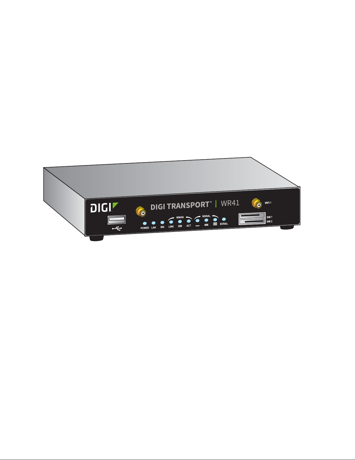
Digi TransPort® routers TransPort WR41
TransPort WR41
The Digi TransPort WR family of cellular routers offers an all-in-one mobile communications solution
with true enterprise class routing, security and firewall. These multifunction cellular routers feature a
flexible design with an optional integrated Wi-Fi access point (with multi SSID) / Client, USB, serial,
and Ethernet, as well as a variety of configuration options including multiple serial ports (async or
sync), GPS or I/O telemetry modules.
The Digi TransPort family also offers an advanced routing, security and firewall feature set including
stateful inspection firewall and integrated VPN. Enterprise class protocols incorporate BGP, OSPF
and VRRP+, a patented technology built upon the popular VRRP failover standard providing true
auto sensing, auto failure and auto recovery of any line drop.
Digi TransPort WR routers are ideal for transportation and mobile applications. Flexible power
options include AC, DC and 4-pin Molex connectors for direct integration into vehicle applications.
Also available is the Digi Remote Manager™ which provides easy setup, configuration and
maintenance of large installations of Digi TransPort devices.
Digi TransPort WR Routers User Guide 20
Page 21

Digi TransPort® routers TransPort WR44 / WR44 R
TransPort WR44 / WR44 R
The Digi TransPort WR44 cellular router is an all-in-one mobile communications solution with true
enterprise-class routing, security and firewall. This multifunction cellular router features a flexible
design with integrated Wi-Fi access point, USB, serial and 4-port Ethernet switch, as well as a variety
of configuration options including multiple serial ports (async or sync), GPS or I/O telemetry
modules.
The Digi TransPort family offers an advanced routing, security and firewall feature set including
stateful inspection firewall and integrated VPN. Enterprise-class protocols incorporate BGP, OSPF
and VRRP+, a patented technology built upon the popular VRRP failover standard providing true
auto sensing, auto failure and auto recovery of any line drop.
Digi TransPort WR44 is ideal for transportation and mobile applications. Flexible power options
include 11-58 VDC barrel or molex connectors for direct integration into vehicle applications. Digi
Remote Manager™ provides easy setup, configuration and maintenance of large installations of Digi
TransPort devices.
Digi TransPort WR Routers User Guide 21
Page 22

Digi TransPort® routers TransPort WR44 RR
TransPort WR44 RR
Digi TransPort WR44 RR is a rugged enterprise-class cellular router designed for rail environments.
Its rail industry ratings, versatility, security features and performance make it ideal for applications
such as Positive Train Control (PTC), wayside device communications and on-board passenger
Internet access.
Digi TransPort WR44 RR provides a reliable primary high speed cellular network connection or can
act as a secure backup connection to the existing railroad network. It features a flexible
communications design with 3G/4G multicarrier GSM/CDMA cellular, plus integrated Wi-Fi a/ac/b/g/
n access point, serial and 4-port Ethernet switch. It also features full on-board train certifications,
including AREMA C/H and EN50155. Communications interfaces include hardened connectors,
including M12 for Ethernet and serial, as well as TNC connectors for antenna connections.
Digi management solutions provide easy setup, configuration and maintenance of large
installations of remote Digi TransPort devices. Digi Remote Manager offers web-based device
management for remote Digi cellular routers and gateways.
Digi TransPort WR Routers User Guide 22
Page 23

Hardware
This section describes hardware specifications and features of TransPort products, presents pinout
information, and covers regulatory and safety statements and certifications.
TransPort WR11 hardware . . . . . . . . . . . . . . . . . . . . . . . . . . . . . . . . . . . . . . . . . . . . . . . . . . . . . . . . . 24
TransPort WR21 hardware . . . . . . . . . . . . . . . . . . . . . . . . . . . . . . . . . . . . . . . . . . . . . . . . . . . . . . . . . 35
TransPort WR31 hardware . . . . . . . . . . . . . . . . . . . . . . . . . . . . . . . . . . . . . . . . . . . . . . . . . . . . . . . . . 43
TransPort WR41 hardware . . . . . . . . . . . . . . . . . . . . . . . . . . . . . . . . . . . . . . . . . . . . . . . . . . . . . . . . . 59
TransPort WR44 / WR44 R hardware . . . . . . . . . . . . . . . . . . . . . . . . . . . . . . . . . . . . . . . . . . . . . . . . . 71
TransPort WR44 RR hardware . . . . . . . . . . . . . . . . . . . . . . . . . . . . . . . . . . . . . . . . . . . . . . . . . . . . . . 85
Signal strength indicators . . . . . . . . . . . . . . . . . . . . . . . . . . . . . . . . . . . . . . . . . . . . . . . . . . . . . . . . . 95
Antenna specifications for Wi-Fi 2.4GHz modules . . . . . . . . . . . . . . . . . . . . . . . . . . . . . . . . . . . . . . . 95
Digi TransPort WR Routers User Guide 23
Page 24

Hardware TransPort WR11 hardware
2
1
3
4
TransPort WR11 hardware
TransPort WR11 EVDO model hardware features
1LAN port: Connects the device to a 10/100 base-T Local Area Network (LAN). The port can
perform auto-sensing for speed and wiring, so it can accept straight-through or cross-over cable
connections.
2Power connector: This locking power connector connects the device to a power source. The
connector should be inserted and rotated to lock in place. Center pin is positive.
3LEDs:
• Service LED: Indicates the presence and level of cellular service running on the device.
Off: No cellular service
1 Blink: Device is running 1xRTT service
2 Blinks: Device is running EDVO Rev 0 service
3 Blinks: Device is running EDVO Rev A service
• Signal LED: Indicates strength of cellular signal.
Off: Poor or No signal. Place the device in a location where it gets a better signal.
Amber: Fair
Green: Good
• Power LED
Off: No power
Digi TransPort WR Routers User Guide 24
Page 25

Hardware TransPort WR11 hardware
2
1
3
4
5
6
Green: TransPort device is powered
4 Cellular antenna connector: This SMA female connector connects the device’s primary cellular
antenna.
TransPort WR11 HSPA+ model hardware features
1LAN port: Connects the device to a 10/100 base-T Local Area Network (LAN). The port can
perform auto-sensing for speed and wiring, so it can accept straight-through or cross-over cable
connections.
2Power connector: This locking power connector connects the device to a power source. The
connector should be inserted and rotated to lock in place. Center pin is positive.
3 LEDs:
• SERVICE LED: Indicates the presence and level of cellular service running on the device.
Off: No cellular service
1 Blink: GPRS mode
2 Blinks: EDGE mode
3 Blinks: UMTS mode
4 Blinks: HSDPA mode
5 Blinks: HSUPA mode
• SIGNAL LED: Indicates strength of cellular signal.
Off: Poor or No signal. Place the device in a location where it gets a better signal.
Amber: Fair
Green: Good
• POWER LED:
Off: No power
Green: TransPort device is powered
Digi TransPort WR Routers User Guide 25
Page 26

Hardware TransPort WR11 hardware
4SIM door: Encloses the SIM sockets. The SIM door must be removed to install the SIM cards For
installation details, refer to the Quick Start Guide that came with your device.
Note To remove the SIM door, hold the device on a flat surface and using a screwdriver, firmly pull
the cover straight up.
5 Cellular antenna connector: This SMA female connector connects the device’s primary cellular
antenna.
6SIM Sockets: SIM 1 and SIM 2 are for use with the Subscriber Identification Module(s) (SIMs).
Digi TransPort WR Routers User Guide 26
Page 27

Hardware TransPort WR11 hardware
3
4 5
7
2
1
6
TransPort WR11 LTE-MIMO hardware features
1LAN port: Connects the device to a 10/100 base-T Local Area Network (LAN). The port can
perform auto-sensing for speed and wiring, so it can accept straight-through or cross-over cable
connections.
Digi TransPort WR Routers User Guide 27
2Power connector: This locking power connector connects the device to a power source. The
connector should be inserted and rotated to lock in place. Center pin is positive.
3LEDs:
• SERVICE LED: Indicates the presence and level of cellular service running on the device.
Off: No cellular service
1 Blink: GPRS mode
2 Blinks: EDGE mode
3 Blinks: UMTS mode
4 Blinks: HSDPA mode
5 Blinks: HSUPA mode
6 Blinks: LTE mode
Page 28

Hardware TransPort WR11 hardware
• SIGNAL LED: Indicates strength of cellular signal.
Off: Poor or No signal. Place the device in a location where it gets a better signal.
Amber: Fair
Green: Good
• POWER LED:
Off: No power
Green: TransPort device is powered
4SIM door: Encloses the SIM sockets. The SIM door must be opened to install the SIM cards. For
installation details, refer to the Quick Start Guide that came with your device.
Note To open the SIM door, slide the SIM door out using your finger.
5SIM sockets: SIM 1 and SIM 2 are for use with the Subscriber Identification Module(s) (SIMs).
6 Primary LTE antenna connector: This SMA female connector connects the device’s primary
cellular antenna.
7 Secondary LTE antenna connector: This SMA female connector connects the device’s
secondary cellular antenna.
Digi TransPort WR Routers User Guide 28
Page 29

Hardware TransPort WR11 hardware
7
2
1
6
5
4
3
TransPort WR11 XT
1LAN port: Connects the device to a 10/100 base-T Local Area Network (LAN). The port can
perform auto-sensing for speed and wiring, so it can accept straight-through or cross-over cable
connections.
2Power connector: This locking power connector connects the device to a power source. The
connector should be inserted and rotated to lock in place. Center pin is positive.
3 LEDs:
• SERVICE LED: Indicates the presence and level of cellular service running on the device.
Off: No cellular service
1 Blink: GPRS mode
2 Blinks: EDGE mode
3 Blinks: UMTS mode
4 Blinks: HSDPA mode
5 Blinks: HSUPA mode
6 Blinks: LTE mode
• SIGNAL LED: Indicates strength of cellular signal.
Off: Poor or No signal. Place the device in a location where it gets a better signal.
Amber: Fair
Digi TransPort WR Routers User Guide 29
Page 30

Hardware TransPort WR11 hardware
Green: Good
• POWER LED:
Off: No power
Green: TransPort device is powered
4SIM door: Encloses the SIM sockets. The SIM door must be opened to install the SIM cards. For
installation details, refer to the Quick Start Guide that came with your device.
5SIM sockets: SIM 1 and SIM 2 are for use with the Subscriber Identification Module(s) (SIMs).
Insert SIM cards with the notch facing the bottom-right corner of the device. If you are using one
SIM card only, insert it in the SIM 1 slot.
6 Primary cellular antenna connector: This SMA female connector connects the device’s primary
cellular antenna.
7 Secondary cellular antenna connector: This SMA female connector connects the device’s
secondary cellular antenna.
TransPort WR11 accessories
A variety of accessories are available for TransPort products. For the current list of accessories and
their Digi part numbers, go to the TransPort WR11 Part Numbers and Accessories page.
TransPort WR11 hardware specifications
For hardware specifications, see Digi TransPort WR11 specifications.
Digi TransPort WR Routers User Guide 30
Page 31

Hardware TransPort WR11 hardware
Regulatory and safety statements
RF exposure statement
In order to comply with RF exposure limits established in the ANSI C95.1 standards, the distance
between the antenna or antennas and the user should not be less than 20 cm.
FCC Part 15 Class B
Radio Frequency Interference (RFI) (FCC 15.105)
This device has been tested and found to comply with the limits for Class B digital devices pursuant
to Part 15 Subpart B, of the FCC rules. These limits are designed to provide reasonable protection
against harmful interference in a residential environment. This equipment generates, uses, and can
radiate radio frequency energy, and if not installed and used in accordance with the instruction
manual, may cause harmful interference to radio communications. However, there is no guarantee
that interference will not occur in a particular installation. If this equipment does cause harmful
interference to radio or television reception, which can be determined by turning the equipment off
and on, the user is encouraged to try and correct the interference by one or more of the following
measures:
Reorient or relocate the receiving antenna.Increase the separation between the equipment and
receiver.Connect the equipment into an outlet on a circuit different from that to which the receiver
is connected.Consult the dealer or an experienced radio/TV technician for help.
Labeling Requirements (FCC 15.19)
This device complies with Part 15 of FCC rules. Operation is subject to the following two conditions:
(1) this device may not cause harmful interference, and (2) this device must accept any interference
received, including interference that may cause undesired operation.
If the FCC ID is not visible when installed inside another device, then the outside of the device into
which the module is installed must also display a label referring to the enclosed module FCC ID.
Modifications (FCC 15.21)
Changes or modifications to this equipment not expressly approved by Digi may void the user’s
authority to operate this equipment.
TransPort WR11 EU Declaration of Conformity
Digi has issued Declarations of Conformity for the Digi TransPort WR11 concerning emissions,
EMC, and safety. For more information, see
Important note
Digi customers assume full responsibility for learning and meeting the required guidelines for
each country in their distribution market. Refer to the radio regulatory agency in the desired
countries of operation for more information.
http://www.digi.com/resources/certifications.
Digi TransPort WR Routers User Guide 31
Page 32

Hardware TransPort WR11 hardware
CE mark (Europe)
The Digi TransPort WR11 is certified for use in several European countries. For information, visit
www.digi.com/resources/certifications.
If the
Digi TransPort WR11 is incorporated into a product, the manufacturer must ensure
compliance of the final product with articles 3.1a and 3.1b of the RE Directive (Radio Equipment
Directive). A Declaration of Conformity must be issued for each of these standards and kept on file
as described in the RE Directive (Radio Equipment Directive).
Furthermore, the manufacturer must maintain a copy of the
documentation and ensure the final product does not exceed the specified power ratings, antenna
specifications, and/or installation requirements as specified in the user manual. If any of these
specifications are exceeded in the final product, a submission must be made to a notified body for
compliance testing to all required standards.
OEM labeling requirements
The “CE” marking must be affixed to a visible location on the OEM product.
CE labeling requirements
Digi TransPort WR11 user manual
The CE mark shall consist of the initials “CE” taking the following form:
▪ If the CE marking is reduced or enlarged, the proportions given in the above graduated drawing
must be respected.
▪ The CE marking must have a height of at least 5mm except where this is not possible on account
of the nature of the apparatus.
▪ The CE marking must be affixed visibly, legibly, and indelibly.
Digi TransPort WR Routers User Guide 32
Page 33

Hardware TransPort WR11 hardware
Maximum power and frequency bands
Max power Frequencies
2 W
1 W
Cellular 850 and 900 MHZ bands
Cellular 850 and 900MHZ bands
Industry Canada (IC) certifications
This digital apparatus does not exceed the Class B limits for radio noise emissions from digital
apparatus set out in the Radio Interference Regulations of the Canadian Department of
Communications.
Le present appareil numerique n’emet pas de bruits radioelectriques depassant les limites
applicables aux appareils numeriques de la class B prescrites dans le Reglement sur le brouillage
radioelectrique edicte par le ministere des Communications du Canada.Radio equipment-Canadian
warning statements
Restricted Access Location notice for Trans Port WR11 XT
Because of the hot metal surface of the enclosure, installations with operating temperatures
greater than 122F (50C) must be limited to Restricted Access Locations accessible only to trained
service personnel.
Safety notices
1 Please read all instructions before installing and powering the router. You should keep these
instructions in a safe place for future reference.
2 If the power supply shows signs of damage or malfunction, stop using it immediately, turn off
the power and disconnect the power supply before contacting your supplier for a repair or
replacement.
3 Changes or modifications not expressly approved by the party responsible for compliance could
void the user’s authority to operate the equipment. Use only the accessories, attachments, and
power supplies provided by the manufacturer-connecting non-approved antennas or power
supplies may damage the router, cause interference or create an electric shock hazard, and will
void the warranty.
4 Do not attempt to repair the product. The router contains no electronic components that can be
serviced or replaced by the user. Any attempt to service or repair the router by the user will void
the product warranty.
5 The TransPort WR11 is designed for indoor use. Use it in an environment suitable for computers
and other electronic equipment.
6 Ports that are capable of connecting to other apparatus are defined as SELV ports. To ensure
conformity with IEC60950 ensure that these ports are only connected to ports of the same type
on other apparatus.
Digi TransPort WR Routers User Guide 33
Page 34

Hardware TransPort WR11 hardware
Special notes on safety for wireless routers
Digi International products are designed to the highest standards of safety and international
standards compliance for the markets in which they are sold. However, cellular-based products
contain radio devices which require specific consideration. Please take the time to read and
understand the following guidance. Digi International assumes no liability for an end user’s failure
to comply with these precautions.
Wireless routers incorporate a wireless radio module. Users should ensure that the antenna(s) is
(are) positioned at least 1 meter away from themselves and other persons in normal operation.
When in a hospital or other health care facility, observe the restrictions on the use of mobile phones.
Do not use the router in areas where guidelines posted in sensitive areas instruct users to switch off
mobile phones. Medical equipment may be sensitive to RF energy.
The operation of cardiac pacemakers, other implanted medical equipment and hearing aids can be
affected by interference from cellular terminals such as the wireless routers when places close to
the device. If in doubt about potential danger, contact the physician or the manufacturer of the
device to verify that the equipment is properly shielded. Pacemaker patients are advised to keep
the wireless router away from the pacemaker while it is on.
Wireless routers must NOT be operated on aircraft. The operation of wireless appliances in an
aircraft is forbidden to prevent interference with communications systems. Failure to observe these
instructions may lead to the suspension or denial of cellular services to the offender, legal action, or
both.
As with any electrical equipment, do not operate the router in the presence of flammable gases,
fumes or potentially explosive atmospheres. Do not use radio devices anywhere that blasting
operations occur.
Wireless routers receive and transmit radio frequency energy when power is on. Interference can
occur when using the router close to TV sets, radios, computers or inadequately shielded
equipment. Follow any special regulations and always power off your router wherever forbidden or
when it may cause interference or danger.
SOS IMPORTANT! Wireless routers operate using radio signals and cellular networks cannot be
guaranteed to connect in all possible conditions. Therefore, never rely solely upon any wireless
device for life critical communications.
Warning: For environments where the temperature is 55° C or above, this device must be installed
in a restricted access area.
Product Disposal Instructions
The WEEE (Waste Electrical and Electronic Equipment: 2002/96/EC) directive has been introduced to
ensure that electrical/ electronic products are recycled using the best available recovery techniques
to minimize the impact on the environment.
This product contains high quality materials and components which can be recycled. At the end of
its life this product MUST NOT be mixed with other commercial waste for disposal. Check with the
terms and conditions of your supplier for disposal information.
Digi International Ltd WEEE Registration number: WEE/HF1515VU
Digi TransPort WR Routers User Guide 34
Page 35

Hardware TransPort WR21 hardware
POWER SERVICE WWAN
SIGNAL
POWER SERVICE WWAN
SIGNAL
SIM 1
SIM 2
WR21DIGI TRANSPORT
®
7
1
5432
6
TransPort WR21 hardware
TransPort WR21 front panel features
1 SIM/R-UIM sockets (SIM card models only): SIM 1 and SIM 2 are for use with the Subscriber
Identification Module(s) (SIMs) or Removable User Identification Module(s) (R-UIMs).
2POWER LED:
• Off: No power
• Green: TransPort device is powered
3SERVICE LED:
• Off: No WWAN network connection
• Green: WWAN network connection
• Flashing: WWAN traffic being transmitted or received
4 WWAN (Wireless Network) LED: Indicates the presence and level of cellular service running on
the device.
• Off: No cellular service
• 1 Blink: GPRS mode
• 2 Blinks: EDGE mode
• 3 Blinks: UMTS mode
• 4 Blinks: HSDPA mode
• 5 Blinks: HSUPA mode
• 6 Blinks: LTE mode
5 SIGNAL LED: Indicate strength of cellular signal.
• 3 LEDs: Excellent
• 2 LEDs: Good
• 1 LED: Fair
• 0 LEDs: Poor or No signal
6 Reset button: Returns the router to its factory default settings.
Digi TransPort WR Routers User Guide 35
Page 36

Hardware TransPort WR21 hardware
7 USB host connector: Connects compatible USB 2.0 client devices such as memory sticks, and
serial adapters. The total current available to power USB devices is 0.5A.
Reset the TransPort WR21
1 Turn the router on and wait 15 seconds for the router to complete its initialization process.
2 Press and hold the reset button gently for 5 seconds. After this time, the router automatically
reboots and display a pattern of alternating LEDs flashing followed by the normal boot
sequence.
CAUTION! Do not remove power from the router during this operation, as corruption of the flash
memory may occur.
Digi TransPort WR Routers User Guide 36
Page 37

Hardware TransPort WR21 hardware
WWAN
SECONDARY
SERIAL 0
9-30VDC
2A MAX
1
2 3
4
6
WWAN
PRIMARY
5
LAN 1LAN 0
WWAN
SECONDARY
SERIAL 0
WWAN
PRIMARY
LAN 1LAN 0
9-30VDC
2A MAX
7
TransPort WR21 rear panel features
1Secondary cellular (WWAN) antenna connector: This SMA female connector connects the
router’s secondary cellular antenna. It is highly recommended to use the secondary antenna for
diversity. In most circumstances, dual antennas provide improved signal strength and better
performance.
2LAN 0 port: This RJ45 port connects the router to a 10/100 base-TLAN. The port is auto-sensing
3LAN 1 port (optional): This RJ45 port connects the router to a 10/100 base-TLAN. The port is
4Serial 0 port: This DB9 port provides an asynchronous RS232 (RS485 optional) serial port with
5Power connector: This connector connects the router to a power source using either the
6 Primary cellular (WWAN) antenna connector: This SMA female connector connects the
7Power cord input (terminal block variant): This socket connects the router to an alternative
for speed and wiring (straight-through or cross-over).
auto- sensing for speed and wiring (straight-through or cross-over).
optional RS422/485 support for connecting the router to a compatible serial device. This is a DCE
serial port and allows CLI access to the device by default; the baud rate is 115200. For a pinout,
see TransPort WR21 serial pinout.
supplied power supply or DC power cord. Secure the barrel plug connector by rotating it by 90
degrees once installed into the Digi TransPort router. Center pin is positive.
router’s primary cellular antenna.
power source.
Digi TransPort WR Routers User Guide 37
Page 38

Hardware TransPort WR21 hardware
WWAN
SECONDARY
SERIAL 0
9-30VDC
2A MAX
WWAN
PRIMARY
LAN 1LAN 0
SERIAL 0
Pin 1
Pin 9
TransPort WR21 serial pinout
Note that all TransPort serial ports are DCE.
RS232 pinout
Pin # Direction RS232 DCE Description
1 Out DCD Data Carrier Detect
2 Out RXD Receive Data
3In TXD Transmit Data
4 In DTR Data Terminal Ready
5N/A GND Ground
6 Out DSR Data Set Ready
7In RTS Ready To Send
8Out CTS Clear To Send
9 Out RI Ring Indicate
RS422/ RS485 pinout
Pin # Direction RS422/ RS485 Description
1 Out CTS- Clear To Send -
2 Out RD+ Receive Data +
3 In TD+ Transmit Data +
4 In RTS_B RTS- Ready To Send -
5N/A GND Ground
6 Out RD- Receive Data -
7In RTS+ Ready To Send +
8 Out CTS+ Clear To Send +
9 In TD- Transmit -
Notes
▪ For true RS485 mode (2-wire half-duplex mode), the TD+ and RD+ pair and TD- and RD- pair
should be connected together.
▪ The CTS and RTS signals are optional and not normally needed for RS485.
Digi TransPort WR Routers User Guide 38
Page 39

Hardware TransPort WR21 hardware
TransPort WR21 accessories
A variety of accessories are available for TransPort products. For the current list of accessories and
their Digi part numbers, go to the TransPort WR21 Part Numbers and Accessories page.
TransPort WR21 hardware specifications
For hardware specifications, see Digi TransPort WR21 hardware specifications.
Regulatory and safety statements
RF exposure statement
In order to comply with RF exposure limits established in the ANSI C95.1 standards, the distance
between the antenna or antennas and the user should not be less than 20 cm.
FCC Part 15 Class B
Radio Frequency Interference (RFI) (FCC 15.105)
This device has been tested and found to comply with the limits for Class B digital devices pursuant
to Part 15 Subpart B, of the FCC rules. These limits are designed to provide reasonable protection
against harmful interference in a residential environment. This equipment generates, uses, and can
radiate radio frequency energy, and if not installed and used in accordance with the instruction
manual, may cause harmful interference to radio communications. However, there is no guarantee
that interference will not occur in a particular installation. If this equipment does cause harmful
interference to radio or television reception, which can be determined by turning the equipment off
and on, the user is encouraged to try and correct the interference by one or more of the following
measures:
Reorient or relocate the receiving antenna.Increase the separation between the equipment and
receiver.Connect the equipment into an outlet on a circuit different from that to which the receiver
is connected.Consult the dealer or an experienced radio/TV technician for help.
Labeling Requirements (FCC 15.19)
This device complies with Part 15 of FCC rules. Operation is subject to the following two conditions:
(1) this device may not cause harmful interference, and (2) this device must accept any interference
received, including interference that may cause undesired operation.
If the FCC ID is not visible when installed inside another device, then the outside of the device into
which the module is installed must also display a label referring to the enclosed module FCC ID.
Modifications (FCC 15.21)
Changes or modifications to this equipment not expressly approved by Digi may void the user’s
authority to operate this equipment.
Digi TransPort WR Routers User Guide 39
Page 40

Hardware TransPort WR21 hardware
TransPort WR21 EU Declaration of Conformity
Digi has issued Declarations of Conformity for the Digi TransPort WR21 concerning emissions,
EMC, and safety. For more information, see
Important note
http://www.digi.com/resources/certifications.
Digi customers assume full responsibility for learning and meeting the required guidelines for
each country in their distribution market. Refer to the radio regulatory agency in the desired
countries of operation for more information.
CE mark (Europe)
The Digi TransPort WR21 is certified for use in several European countries. For information, visit
www.digi.com/resources/certifications.
Digi TransPort WR21 is incorporated into a product, the manufacturer must ensure
If the
compliance of the final product with articles 3.1a and 3.1b of the RE Directive (Radio Equipment
Directive). A Declaration of Conformity must be issued for each of these standards and kept on file
as described in the RE Directive (Radio Equipment Directive).
Furthermore, the manufacturer must maintain a copy of the
documentation and ensure the final product does not exceed the specified power ratings, antenna
specifications, and/or installation requirements as specified in the user manual. If any of these
specifications are exceeded in the final product, a submission must be made to a notified body for
compliance testing to all required standards.
OEM labeling requirements
The “CE” marking must be affixed to a visible location on the OEM product.
CE labeling requirements
Digi TransPort WR21 user manual
The CE mark shall consist of the initials “CE” taking the following form:
▪ If the CE marking is reduced or enlarged, the proportions given in the above graduated drawing
must be respected.
▪ The CE marking must have a height of at least 5mm except where this is not possible on account
of the nature of the apparatus.
▪ The CE marking must be affixed visibly, legibly, and indelibly.
Digi TransPort WR Routers User Guide 40
Page 41

Hardware TransPort WR21 hardware
Maximum power and frequency bands
Max power Frequencies
2 W
1 W
200 mW
Cellular 850 and 900 MHz bands
Cellular 1800 and 1900 MHz Bands
Cellular @450 MHz Band
Industry Canada (IC) certifications
This digital apparatus does not exceed the Class B limits for radio noise emissions from digital
apparatus set out in the Radio Interference Regulations of the Canadian Department of
Communications.
Le present appareil numerique n’emet pas de bruits radioelectriques depassant les limites
applicables aux appareils numeriques de la class B prescrites dans le Reglement sur le brouillage
radioelectrique edicte par le ministere des Communications du Canada.
Hazardous Location installation information for TransPort WR21
For Hazardous Location installation, see the TransPort WR21 Hazardous Location User Guide (Digi
part number 90001532).
Safety notices
1 Please read all instructions before installing and powering the router. You should keep these
instructions in a safe place for future reference.
2 If the power supply shows signs of damage or malfunction, stop using it immediately, turn off
the power and disconnect the power supply before contacting your supplier for a repair or
replacement.
3 Changes or modifications not expressly approved by the party responsible for compliance could
void the user’s authority to operate the equipment. Use only the accessories, attachments, and
power supplies provided by the manufacturer-connecting non-approved antennas or power
supplies may damage the router, cause interference or create an electric shock hazard, and will
void the warranty.
4 Do not attempt to repair the product. The router contains no electronic components that can be
serviced or replaced by the user. Any attempt to service or repair the router by the user will void
the product warranty.
5 The TransPort WR21 is designed for indoor use. Use it in an environment suitable for computers
and other electronic equipment.
6 Ports that are capable of connecting to other apparatus are defined as SELV ports. To ensure
conformity with IEC60950 ensure that these ports are only connected to ports of the same type
on other apparatus.
Digi TransPort WR Routers User Guide 41
Page 42

Hardware TransPort WR21 hardware
Special notes on safety for wireless routers
Digi International products are designed to the highest standards of safety and international
standards compliance for the markets in which they are sold. However, cellular-based products
contain radio devices which require specific consideration. Please take the time to read and
understand the following guidance. Digi International assumes no liability for an end user’s failure
to comply with these precautions.
Wireless routers incorporate a wireless radio module. Users should ensure that the antenna(s) is
(are) positioned at least 1 meter away from themselves and other persons in normal operation.
When in a hospital or other health care facility, observe the restrictions on the use of mobile phones.
Do not use the router in areas where guidelines posted in sensitive areas instruct users to switch off
mobile phones. Medical equipment may be sensitive to RF energy.
The operation of cardiac pacemakers, other implanted medical equipment and hearing aids can be
affected by interference from cellular terminals such as the wireless routers when places close to
the device. If in doubt about potential danger, contact the physician or the manufacturer of the
device to verify that the equipment is properly shielded. Pacemaker patients are advised to keep
the wireless router away from the pacemaker while it is on.
Wireless routers must NOT be operated on aircraft. The operation of wireless appliances in an
aircraft is forbidden to prevent interference with communications systems. Failure to observe these
instructions may lead to the suspension or denial of cellular services to the offender, legal action, or
both.
As with any electrical equipment, do not operate the router in the presence of flammable gases,
fumes or potentially explosive atmospheres. Do not use radio devices anywhere that blasting
operations occur.
Wireless routers receive and transmit radio frequency energy when power is on. Interference can
occur when using the router close to TV sets, radios, computers or inadequately shielded
equipment. Follow any special regulations and always power off your router wherever forbidden or
when it may cause interference or danger.
SOS IMPORTANT! Wireless routers operate using radio signals and cellular networks cannot be
guaranteed to connect in all possible conditions. Therefore, never rely solely upon any wireless
device for life critical communications.
Warning: For environments where the temperature is 55° C or above, this device must be installed
in a restricted access area.
Product Disposal Instructions
The WEEE (Waste Electrical and Electronic Equipment: 2002/96/EC) directive has been introduced to
ensure that electrical/ electronic products are recycled using the best available recovery techniques
to minimize the impact on the environment.
This product contains high quality materials and components which can be recycled. At the end of
its life this product MUST NOT be mixed with other commercial waste for disposal. Check with the
terms and conditions of your supplier for disposal information.
Digi International Ltd WEEE Registration number: WEE/HF1515VU
Digi TransPort WR Routers User Guide 42
Page 43

Hardware TransPort WR31 hardware
0
WWAN PRI
9-30VDC
2A MAX
1
0
WWAN PRI
9-30VDC
2A MAX
2
0
WWAN PRI
9-30VDC
2A MAX
1
3
5
6
7
WW
AN PRI
9-30VDC
2
A MAX
9
8
12
11
10
4
TransPort WR31 hardware
TransPort WR31 hardware features
Digi TransPort WR Routers User Guide 43
Page 44

Hardware TransPort WR31 hardware
1 SIM card slot cover: On the underside of the router. Remove and replace with a Phillips-head
screwdriver.
2 SIM 1 and SIM 2 card slots: On the underside of the router. SIM 1 and SIM 2 are for use with the
Subscriber Identification Module(s) (SIMs) or Removable User Identification Module(s) (R-UIMs).
when inserting the SIM card(s) into SIM sockets, SIM 1 is to the middle of the router, and SIM 2 is
toward the outside of the router. In both cases, the end of the SIM card with the chamfered
corner should be inserted first.
3LAN 0 port: This RJ45 port connects the router to a 10/100 base-TLAN. The port is auto-sensing
for speed and wiring (straight-through or cross-over).
4LAN 1 port: This RJ45 port connects the router to a 10/100 base-TLAN. The port is auto- sensing
for speed and wiring (straight-through or cross-over).
5 USB host connector: Connects compatible USB 2.0 client devices such as memory sticks, and
serial adapters. The total current available to power USB devices is 0.5A.
WARNING! The USB port is for use in a normal location only, not a hazardous location.
6 Serial connector: This DB9 port provides an asynchronous RS232 (RS485 optional) serial port
with optional RS422/485 support to connect the router to a compatible serial device. This is a
DCE serial port and allows CLI access to the device by default; the default serial baud rate is
115200. For a pinout, see TransPort WR31 serial pinout.
7Power connector: A pluggable connector that connects the router to a power source using
either the separately available power supply: Digi part number 76000736, or a DIN rail power
supply.
8WWAN primary connector: This SMA male connector connects the router’s primary cellular
antenna.
9 WWAN secondary connector: This SMA male connector connects the router’s secondary
cellular antenna. For multiple-input and multiple-output (MIMO), both cellular antennas are
needed for downloading data.
10 LEDs: Indicate startup states and status for various signals and services:
• POWER LED:
Off: No power
Green: TransPort device is powered
• SERVICE LED:
Off: No WWAN network connection
Green: WWAN network connection
Flashing: WWAN traffic being transmitted or received
• WWAN LED: Indicates the presence and level of cellular service running on the device.
Off: No cellular service
1 Blink: GPRS mode
2 Blinks: EDGE mode
3 Blinks: UMTS mode
4 Blinks: HSDPA mode
Digi TransPort WR Routers User Guide 44
Page 45

Hardware TransPort WR31 hardware
5 Blinks: HSUPA mode
6 Blinks: LTE mode
• SIGNAL LEDs: Indicate strength of cellular signal.
3 LEDs: Excellent
2 LEDs: Good
1 LED: Fair
0 LEDs: Poor or No signal
• SYSTEM LED: Reserved for user-defined functions.
11 Earth ground
12 Digital/analog I/O connector:
An input/output connector with two digital input/output
connections, and a single analog input connection. For more information and wiring
diagrams, see
TransPort WR31 digital and analog inputs and outputs.
Digi TransPort WR Routers User Guide 45
Page 46

Hardware TransPort WR31 hardware
TransPort WR31 hardware specifications
For hardware specifications, see Digi TransPort WR31 specifications.
TransPort WR31 accessories
A variety of accessories are available for TransPort products. For the current list of accessories and
their Digi part numbers, go to the TransPort WR31 Part Numbers and Accessories page.
TransPort WR31 mounting options
You can mount the TransPort WR31 on a DIN rail, directly to a wall, or in a NEMA enclosure. For wallmounting or NEMA enclosure installation, purchase the TransPort WR31 Wall Mount Bracket (Digi
part number 76000963) and NEMA enclosure equipment, such as the NEMA enclosure, mounting
plate, special cabling, and cable glands.
Hazardous Location installation
For Hazardous Location installation, see the TransPort WR31 Hazardous Locations User Guide (Digi
part number 90001490) on www.digi.com.
Digi TransPort WR Routers User Guide 46
Page 47

Hardware TransPort WR31 hardware
WWAN PRI
9-30VDC
2A MAX
Pin 1
Pin 9
TransPort WR31 serial pinout
Note that all TransPort serial ports are DCE.
Digi TransPort WR Routers User Guide 47
Page 48

Hardware TransPort WR31 hardware
RS232 pinout
Pin # Direction RS232 DCE Description
1 Out DCD Data Carrier Detect
2 Out RXD Receive Data
3In TXD Transmit Data
4 In DTR Data Terminal Ready
5N/A GND Ground
6 Out DSR Data Set Ready
7In RTS Ready To Send
8Out CTS Clear To Send
9 Out RI Ring Indicate
RS422/ RS485 pinout
Pin # Direction RS422/ RS485 Description
1 Out CTS- Clear To Send -
2 Out RD+ Receive Data +
3 In TD+ Transmit Data +
4 In RTS_B RTS- Ready To Send -
5N/A GND Ground
6 Out RD- Receive Data -
7In RTS+ Ready To Send +
8 Out CTS+ Clear To Send +
9 In TD- Transmit -
Notes
▪ For true RS485 mode (2-wire half-duplex mode), the TD+ and RD+ pair and TD- and RD- pair
should be connected together.
▪ The CTS and RTS signals are optional normally not needed for RS485.
Digi TransPort WR Routers User Guide 48
Page 49

Hardware TransPort WR31 hardware
TransPort WR31 digital and analog inputs and outputs
The TransPort WR31 has an input/output connector with two digital input/output connec‐
tions, and a single analog input connection.
I/O connector pin assignments
The figure and table show the I/O connector, pin assignments, and the signals for each pin.
Pin 5
Pin 1
Pin # Symbol Description
5AIN0 Analog Input 0
4AGND Analog Return
3 DIO0 Digital I/O 0
2GND Digital Return
1 DIO1 Digital I/O 1
Digi TransPort WR Routers User Guide 49
Page 50

Hardware TransPort WR31 hardware
WR31_3v3
PullͲupEnableSignal
DigitalOutputEnable
DigitalInput
DIGITALINPUT
DIGITALRETURN
200ͲOhm
AnalogSelectSignal
AnalogInput
ANALOGINPUT
ANALOGRETURN
CurrentLoop
Protector
CurrentLoopSignal
VoltageInputSignal
TransPort WR31 digital input/output: representative circuit
TransPort WR31 analog input: representative circuit
Example digital and analog I/O wiring
Digi TransPort WR Routers User Guide 50
Page 51

Hardware TransPort WR31 hardware
DIGITALINPUT
DIGITALRETURN
DigitalInput
WR31_3v3
PullͲupON
ExternalContact
(DoorContact,
etc.)
DIGITALINPUT
DIGITALRETURN
DigitalInput
ExternalContact
(DoorContact,
etc.)
DigitalOutputEnable
DIGITALRETURN
DIGITALINPUT
Digital input with pullup
Digital input without pullup
Note that input is HIGH when the contact is CLOSED.
Digital output
The wiring diagram assumes a current-limiting resistor provided by installation or connected device
is in use.
Digi TransPort WR Routers User Guide 51
Page 52

Hardware TransPort WR31 hardware
200ͲOhm
AnalogInput
CurrentLoop
Protector
ANALOGINPUT
ANALOGRETURN
ANALOG4Ͳ20mA
Sensor
AnalogSelectSignal
(CurrentMode)
AnalogInput
ANALOGINPUT
ANALOGRETURN
0–10Vinput
AnalogSelectSignal
(VoltageMode)
DC
Analog input, 4-20mA input mode
Analog input, 0-10V input mode
Digi TransPort WR Routers User Guide 52
Page 53

Hardware TransPort WR31 hardware
Digital and analog I/O specifications
Digital I/O specifications
Specification Min Nom Max Units
Rated Input Voltage -0.2 30 V
Rated Input Current -1.0 200 mA
Pull-Up Resistance 10 k Ohms
Digital input specifications
▪ This input is a non-inverting Schmitt-trigger input.
▪ The default state at power-up with no voltage applied is LOW.
Specification Min Nom Max Units
+ Threshold .. 1.6 .. V
- Threshold .. 1.0 .. V
Input impedance 1 M Ohms
Digital output
▪ This output is an open-collector, sinking driver output.
▪ The default state at power-up is off.
Specification Min Nom Max Units
Sink Current .. .. 200 mA
Pull-up Voltage 3 V
Digi TransPort WR Routers User Guide 53
Page 54

Hardware TransPort WR31 hardware
Analog input specifications
Specification Min Nom Max Units
Resolution .. .. 12 BITS
Accuracy .. .. 0.2 %
Rated Input Voltage -0.2 30 V
Rated Input Current 0 40 mA
Voltage input mode (default)
Specification Min Nom Max Units
Input Voltage -0.2 .. 10.25 V
Input Impedance .. 291 K .. Ohms
Current loop mode
Specification Min Nom Max Units
Minimum Input Voltage .. 2 .. V
Load Resistance .. 200 .. Ohms
Digi TransPort WR Routers User Guide 54
Page 55

Hardware TransPort WR31 hardware
Regulatory and safety statements
RF exposure statement
In order to comply with RF exposure limits established in the ANSI C95.1 standards, the distance
between the antenna or antennas and the user should not be less than 20 cm.
FCC Part 15 Class B
Radio Frequency Interference (RFI) (FCC 15.105)
This device has been tested and found to comply with the limits for Class B digital devices pursuant
to Part 15 Subpart B, of the FCC rules. These limits are designed to provide reasonable protection
against harmful interference in a residential environment. This equipment generates, uses, and can
radiate radio frequency energy, and if not installed and used in accordance with the instruction
manual, may cause harmful interference to radio communications. However, there is no guarantee
that interference will not occur in a particular installation. If this equipment does cause harmful
interference to radio or television reception, which can be determined by turning the equipment off
and on, the user is encouraged to try and correct the interference by one or more of the following
measures:
Reorient or relocate the receiving antenna.Increase the separation between the equipment and
receiver.Connect the equipment into an outlet on a circuit different from that to which the receiver
is connected.Consult the dealer or an experienced radio/TV technician for help.
Labeling Requirements (FCC 15.19)
This device complies with Part 15 of FCC rules. Operation is subject to the following two conditions:
(1) this device may not cause harmful interference, and (2) this device must accept any interference
received, including interference that may cause undesired operation.
If the FCC ID is not visible when installed inside another device, then the outside of the device into
which the module is installed must also display a label referring to the enclosed module FCC ID.
Modifications (FCC 15.21)
Changes or modifications to this equipment not expressly approved by Digi may void the user’s
authority to operate this equipment.
TransPort WR31 EU Declaration of Conformity
Digi has issued Declarations of Conformity for the Digi TransPort WR31 concerning emissions,
EMC, and safety. For more information, see
Important note
Digi customers assume full responsibility for learning and meeting the required guidelines for
each country in their distribution market. Refer to the radio regulatory agency in the desired
countries of operation for more information.
http://www.digi.com/resources/certifications.
Digi TransPort WR Routers User Guide 55
Page 56

Hardware TransPort WR31 hardware
CE mark (Europe)
The Digi TransPort WR31 is certified for use in several European countries. For information, visit
www.digi.com/resources/certifications.
If the
Digi TransPort WR31 is incorporated into a product, the manufacturer must ensure
compliance of the final product with articles 3.1a and 3.1b of the RE Directive (Radio Equipment
Directive). A Declaration of Conformity must be issued for each of these standards and kept on file
as described in the RE Directive (Radio Equipment Directive).
Furthermore, the manufacturer must maintain a copy of the
documentation and ensure the final product does not exceed the specified power ratings, antenna
specifications, and/or installation requirements as specified in the user manual. If any of these
specifications are exceeded in the final product, a submission must be made to a notified body for
compliance testing to all required standards.
OEM labeling requirements
The “CE” marking must be affixed to a visible location on the OEM product.
CE labeling requirements
Digi TransPort WR31 user manual
The CE mark shall consist of the initials “CE” taking the following form:
▪ If the CE marking is reduced or enlarged, the proportions given in the above graduated drawing
must be respected.
▪ The CE marking must have a height of at least 5mm except where this is not possible on account
of the nature of the apparatus.
▪ The CE marking must be affixed visibly, legibly, and indelibly.
Digi TransPort WR Routers User Guide 56
Page 57

Hardware TransPort WR31 hardware
Maximum power and frequency bands
Max power Frequencies
2 W
1 W
200 mW
Cellular 850 and 900 MHz bands
Cellular 1800 and 1900 MHz bands
Cellular @450 MHz band
Industry Canada (IC) certifications
This digital apparatus does not exceed the Class B limits for radio noise emissions from digital
apparatus set out in the Radio Interference Regulations of the Canadian Department of
Communications.
Le present appareil numerique n’emet pas de bruits radioelectriques depassant les limites
applicables aux appareils numeriques de la class B prescrites dans le Reglement sur le brouillage
radioelectrique edicte par le ministere des Communications du Canada.
Hazardous Location installation information for TransPort WR31
For Hazardous Location installation, see the TransPort WR31 Hazardous Location User Guide (Digi
part number 90001490).
Safety notices
1 Please read all instructions before installing and powering the router. You should keep these
instructions in a safe place for future reference.
2 If the power supply shows signs of damage or malfunction, stop using it immediately, turn off
the power and disconnect the power supply before contacting your supplier for a repair or
replacement.
3 Changes or modifications not expressly approved by the party responsible for compliance could
void the user’s authority to operate the equipment. Use only the accessories, attachments, and
power supplies provided by the manufacturer-connecting non-approved antennas or power
supplies may damage the router, cause interference or create an electric shock hazard, and will
void the warranty.
4 Do not attempt to repair the product. The router contains no electronic components that can be
serviced or replaced by the user. Any attempt to service or repair the router by the user will void
the product warranty.
5 The TransPort WR31 is designed for indoor use. Use it in an environment suitable for computers
and other electronic equipment.
6 Ports that are capable of connecting to other apparatus are defined as SELV ports. To ensure
conformity with IEC60950 ensure that these ports are only connected to ports of the same type
on other apparatus.
Digi TransPort WR Routers User Guide 57
Page 58

Hardware TransPort WR31 hardware
Special notes on safety for wireless routers
Digi International products are designed to the highest standards of safety and international
standards compliance for the markets in which they are sold. However, cellular-based products
contain radio devices which require specific consideration. Please take the time to read and
understand the following guidance. Digi International assumes no liability for an end user’s failure
to comply with these precautions.
Wireless routers incorporate a wireless radio module. Users should ensure that the antenna(s) is
(are) positioned at least 1 meter away from themselves and other persons in normal operation.
When in a hospital or other health care facility, observe the restrictions on the use of mobile phones.
Do not use the router in areas where guidelines posted in sensitive areas instruct users to switch off
mobile phones. Medical equipment may be sensitive to RF energy.
The operation of cardiac pacemakers, other implanted medical equipment and hearing aids can be
affected by interference from cellular terminals such as the wireless routers when places close to
the device. If in doubt about potential danger, contact the physician or the manufacturer of the
device to verify that the equipment is properly shielded. Pacemaker patients are advised to keep
the wireless router away from the pacemaker while it is on.
Wireless routers must NOT be operated on aircraft. The operation of wireless appliances in an
aircraft is forbidden to prevent interference with communications systems. Failure to observe these
instructions may lead to the suspension or denial of cellular services to the offender, legal action, or
both.
As with any electrical equipment, do not operate the router in the presence of flammable gases,
fumes or potentially explosive atmospheres. Do not use radio devices anywhere that blasting
operations occur.
Wireless routers receive and transmit radio frequency energy when power is on. Interference can
occur when using the router close to TV sets, radios, computers or inadequately shielded
equipment. Follow any special regulations and always power off your router wherever forbidden or
when it may cause interference or danger.
SOS IMPORTANT! Wireless routers operate using radio signals and cellular networks cannot be
guaranteed to connect in all possible conditions. Therefore, never rely solely upon any wireless
device for life critical communications.
Warning: For environments where the temperature is 55° C or above, this device must be installed
in a restricted access area.
Product Disposal Instructions
The WEEE (Waste Electrical and Electronic Equipment: 2002/96/EC) directive has been introduced to
ensure that electrical/ electronic products are recycled using the best available recovery techniques
to minimize the impact on the environment.
This product contains high quality materials and components which can be recycled. At the end of
its life this product MUST NOT be mixed with other commercial waste for disposal. Check with the
terms and conditions of your supplier for disposal information.
Digi International Ltd WEEE Registration number: WEE/HF1515VU
Digi TransPort WR Routers User Guide 58
Page 59

Hardware TransPort WR41 hardware
1
11
10
9876543
2
12
TransPort WR41 hardware
TransPort WR41 front panel features
1 USB host connector: Connects compatible USB 2.0 client devices such as memory sticks, and
serial adapters. The total current available to power USB devices is 0.5A.
2POWER LED:
• Off: No power
• Green: TransPort device is powered
3LAN LED: Illuminates steadily when there is a network connection to the LAN port and flashes
when data is transmitted or received.
4WN LED:
• Wi-Fi models: Illuminates steady if Wi-Fi activity is present.
• Non-Wi-Fi models: Flashes to show which network mode the router is operating in:
Off: No service
1 blink: GPRS mode
2 blinks: EDGE mode
3 blinks: UMTS mode
4 blinks: HSDPA mode
5 blinks: HSUPA mode
6 blinks: LTE mode
5LINK LED: Illuminates steadily when a wireless WAN data connection has been established.
6SIM LED: Illuminates steadily when a valid SIM card is installed.
7ACT LED: Flashes to indicate that data is being transferred over the wireless WAN network.
8 SIGNAL LEDs: Indicate strength of cellular signal.
• 3 LEDs: Excellent
• 2 LEDs: Good
• 1 LED: Fair
• 0 LEDs: Poor or No signal
Digi TransPort WR Routers User Guide 59
Page 60

Hardware TransPort WR41 hardware
9 SERIAL LED: Illuminates steady if a terminal is connected to the SERIAL port and the DTR signal
is on. Flashes when data is transmitted or received.
10 SIM / R-UIM Sockets (SIM card models only): SIM 1 and SIM 2 are for use with the Subscriber
Identification Module(s) (SIMs) or Removable User Identification Module(s) (R-UIMs).
11 Primary Wi-Fi antenna connector (Wi-Fi models only): This SMA connector connects the
router’s primary Wi-Fi antenna.
12 Secondary Wi-Fi antenna connector (Wi-Fi models only): This SMA connector connects the
router’s secondary Wi-Fi antenna.
Digi TransPort WR Routers User Guide 60
Page 61

Hardware TransPort WR41 hardware
WWAN
SECONDARY
WWAN
PRIMARY
LAN
GND
SERIAL 0
1
2
3
4
5
6
7
9-48VDC
2A MAX
WWAN
TransPort WR41 rear panel features
1
WWAN
2
9-48VDC
3
4
SERIAL 0
5
GND
6
PRIMARY
7
LAN
1 WWAN Secondary Antenna Connector (WR41-U and WR41-C models): An SMA female
connector that connects the unit’s secondary cellular antenna. It is highly recommended to use
the secondary antenna for diversity. In most circumstances, dual antennas provide improved
signal strength and better performance.
2Power connector: Connects the router to a power source. The power cord input can be AC, DC
and 4-pin Molex connectors. Secure the barrel plug connector by rotating it by 90 degrees once
installed into the Digi TransPort router. Center pin is positive.
3Serial 0 Port: This RJ45 port provides an asynchronous RS232 serial port for connecting the unit
to a compatible serial device. This is a DCE serial port and allows CLI access to the device by
default; the baud rate is 115200. See TransPort WR41 serial pinout for a pinout diagram.
4 Hardware Expansion Port: Various hardware upgrades are available for this unit and are
populated via this expansion port. See TransPort WR41 additional hardware features for further
information.
5Case Ground: Connect an additional case ground if necessary.
6 WWAN Primary Antenna Connector: An SMA female connector that connects the unit’s primary
cellular antenna.
7LAN Port: This RJ45 port connects the unit to a 10/100 base-T LAN. The port performs auto-
sensing for speed and wiring, and can handle a straight-through or cross-over cable.
Digi TransPort WR Routers User Guide 61
Page 62

Hardware TransPort WR41 hardware
Front of unit
Rear of unit
TransPort WR41 under-unit features
Reset button
The reset button allows the user to return the router to its factory default settings. It is recessed [to
avoid accidental reset], and can be accessed via a small 2.5mm hole located on the underside of the
router.
Reset the router
1 Turn the router on and wait 15 seconds for the router to complete its initialization process.
2 Press and hold the reset button gently for 5 seconds. After this time, the router will automatically
re-boot and display a pattern of alternating LEDs flashing followed by the normal boot
sequence.
CAUTION! Do not remove power from the router during this operation, as corruption of the flash
memory may occur.
Digi TransPort WR Routers User Guide 62
Page 63

Hardware TransPort WR41 hardware
ANT.
(AUX.)
ANT.
(MAIN)
LAN
GND
ASY 0
9-48VDC
2A MAX
SERIAL 1
ISDN
SERIAL 1
SERIAL 3
SERIAL 2
Option 1: ASY Serial Port
Option 3: SYN/ASYN Serial Port
Option 5: ISDN
Option 10: ISDN-U/PSTN
PSTN
Option 9: PSTN
ISDN
Modem
Option 11: DialServ
To Modem
Option 2: ASY Serial Port (3x)
GPS
Option 4: GPS
Option 6: Telemetr y 1 I/O Interface
AB AB
+
_
DC IN
RLY
IN OUT 1 OUT 2
OUT 3
+_+_+
_
OUT 4
Option 7: Telemetr y 2 I/O Interface
ABAB
AB
A
B
D1 D2 D3 D4
AN1
AN2
AN3 AN4 D12C
D34C
Option 8: Fleet I/O Interface
Pwr Data
GPS
SERIAL 1
TransPort WR41 additional hardware features
Digi TransPort WR Routers User Guide 63
Page 64

Hardware TransPort WR41 hardware
1ASY Serial Port: Provides an additional asynchronous RS232 serial port using a DB25 connector.
2ASY Serial Port (3x): Provides three additional asynchronous RS232 serial ports using RJ45
connectors.
3SYN/ASYN Serial Port: Provides an X.21/RS422/RS232 synchronous / asynchronous serial port
using a DB25 connector.
4GPS: Provides GPS capabilities using an SMA male connector.
5ISDN: Provides an ISDN Basic Rate Interface (BRI) via an RJ45 port. This can be configured either
as a TE (terminal endpoint) or as NT-1 (network termination). The option also includes an
additional asynchronous serial port via a second RJ45 port.
6 Telemetry 1 I/O Interface: Provides 4 opto-isolated digital input ports and 1 opto-isolated
digital output port. It also provides a relay I/O port, a voltage monitoring port, and internal
temperature monitoring.
7 Telemetry 2 I/O Interface: Provides 4 isolated analog I/O ports and 4 non-isolated digital I/O
ports.
8 Fleet I/O Interface: Provides a CAN and J1708 interface, GPS, 4 non-isolated digital I/O ports,
ignition sense port, and a 3-axis accelerometer.
9PSTN: Provides a PSTN interface via an RJ45 connector for dialing out and receiving calls.
10 ISDN-U/PSTN: Provides an ISDN-U interface suitable for the USA plus PSTN interface. It can be
configured for Bell-103 modulation in leased line mode as well as a normal PSTN interface.
11 DialServ: This RJ11/FXS connection converts a PSTN analog modem to a RS-232 serial signal.
For more information on the Telemetry 1 Interface, Telemetry 2 Interface, and the Fleet I/O
Interface, see the product specific user’s guides, available on www digi.com on the TransPort WR41
Product Support page.
Digi TransPort WR Routers User Guide 64
Page 65

Hardware TransPort WR41 hardware
TransPort WR41 hardware specifications
For hardware specifications, see Digi TransPort WR41 specifications.
TransPort WR41 accessories
A variety of accessories are available for TransPort products. For the current list of accessories and
their Digi part numbers, go to the TransPort WR41 Part Numbers and Accessories page.
Digi TransPort WR Routers User Guide 65
Page 66

Hardware TransPort WR41 hardware
WWAN
SECONDARY
WWAN
PRIMARY
LAN
GND
SERIAL 0
9-48VDC
2A MAX
SERIAL 0
Pin 8Pin 1
DB25 connector available
on some daughter cards
TransPort WR41 serial pinout
Note that all TransPort serial ports are DCE.
RS232 port pinouts
Description RS232 signal Direction DB 25 Pin#
Transmit Data TxD in 2 6
Receive Data RxD out 3 3
Ready To Send RTS in 4 1
Clear To Send CTS out 5 8
Data Set Ready DSR out 6 n/a
Ground GND n/a 7 5
Data Carrier Detect DCD out 8 7
Transmitter Clock TxC out 15 n/a
Receiver Clock RxC out 17 n/a
Data Terminal Ready DTR in 20 2
Ring Indicate RI out 22 n/a
External Transmitter Clock ETC in 24 n/a
RJ45 Pin#
Digi TransPort WR Routers User Guide 66
Page 67

Hardware TransPort WR41 hardware
Regulatory and safety statements
RF exposure statement
In order to comply with RF exposure limits established in the ANSI C95.1 standards, the distance
between the antenna or antennas and the user should not be less than 20 cm.
FCC Part 15 Class B
Radio Frequency Interference (RFI) (FCC 15.105)
This device has been tested and found to comply with the limits for Class B digital devices pursuant
to Part 15 Subpart B, of the FCC rules. These limits are designed to provide reasonable protection
against harmful interference in a residential environment. This equipment generates, uses, and can
radiate radio frequency energy, and if not installed and used in accordance with the instruction
manual, may cause harmful interference to radio communications. However, there is no guarantee
that interference will not occur in a particular installation. If this equipment does cause harmful
interference to radio or television reception, which can be determined by turning the equipment off
and on, the user is encouraged to try and correct the interference by one or more of the following
measures:
Reorient or relocate the receiving antenna.Increase the separation between the equipment and
receiver.Connect the equipment into an outlet on a circuit different from that to which the receiver
is connected.Consult the dealer or an experienced radio/TV technician for help.
Labeling Requirements (FCC 15.19)
This device complies with Part 15 of FCC rules. Operation is subject to the following two conditions:
(1) this device may not cause harmful interference, and (2) this device must accept any interference
received, including interference that may cause undesired operation.
If the FCC ID is not visible when installed inside another device, then the outside of the device into
which the module is installed must also display a label referring to the enclosed module FCC ID.
Modifications (FCC 15.21)
Changes or modifications to this equipment not expressly approved by Digi may void the user’s
authority to operate this equipment.
TransPort WR41 EU Declaration of Conformity
Digi has issued Declarations of Conformity for the Digi TransPort WR41 concerning emissions,
EMC, and safety. For more information, see
Important note
Digi customers assume full responsibility for learning and meeting the required guidelines for
each country in their distribution market. Refer to the radio regulatory agency in the desired
countries of operation for more information.
http://www.digi.com/resources/certifications.
Digi TransPort WR Routers User Guide 67
Page 68

Hardware TransPort WR41 hardware
CE mark (Europe)
The Digi TransPort WR41 is certified for use in several European countries. For information, visit
www.digi.com/resources/certifications.
If the
Digi TransPort WR41 is incorporated into a product, the manufacturer must ensure
compliance of the final product with articles 3.1a and 3.1b of the RE Directive (Radio Equipment
Directive). A Declaration of Conformity must be issued for each of these standards and kept on file
as described in the RE Directive (Radio Equipment Directive).
Furthermore, the manufacturer must maintain a copy of the
documentation and ensure the final product does not exceed the specified power ratings, antenna
specifications, and/or installation requirements as specified in the user manual. If any of these
specifications are exceeded in the final product, a submission must be made to a notified body for
compliance testing to all required standards.
OEM labeling requirements
The “CE” marking must be affixed to a visible location on the OEM product.
CE labeling requirements
Digi TransPort WR41 user manual
The CE mark shall consist of the initials “CE” taking the following form:
▪ If the CE marking is reduced or enlarged, the proportions given in the above graduated drawing
must be respected.
▪ The CE marking must have a height of at least 5mm except where this is not possible on account
of the nature of the apparatus.
▪ The CE marking must be affixed visibly, legibly, and indelibly.
Digi TransPort WR Routers User Guide 68
Page 69

Hardware TransPort WR41 hardware
Maximum power and frequency bands
Max power Frequencies
2 W
1 W
Cellular 850 and 900 MHz bands
Cellular 1800 and 1900 MHz bands
Industry Canada (IC) certifications
This digital apparatus does not exceed the Class B limits for radio noise emissions from digital
apparatus set out in the Radio Interference Regulations of the Canadian Department of
Communications.
Le present appareil numerique n’emet pas de bruits radioelectriques depassant les limites
applicables aux appareils numeriques de la class B prescrites dans le Reglement sur le brouillage
radioelectrique edicte par le ministere des Communications du Canada.
Safety notices
1 Please read all instructions before installing and powering the router. You should keep these
instructions in a safe place for future reference.
2 If the power supply shows signs of damage or malfunction, stop using it immediately, turn off
the power and disconnect the power supply before contacting your supplier for a repair or
replacement.
3 Changes or modifications not expressly approved by the party responsible for compliance could
void the user’s authority to operate the equipment. Use only the accessories, attachments, and
power supplies provided by the manufacturer-connecting non-approved antennas or power
supplies may damage the router, cause interference or create an electric shock hazard, and will
void the warranty.
4 Do not attempt to repair the product. The router contains no electronic components that can be
serviced or replaced by the user. Any attempt to service or repair the router by the user will void
the product warranty.
5 Products in the TransPort WR
them in an environment suitable for computers and other electronic equipment.
6 Ports that are capable of connecting to other apparatus are defined as SELV ports. To ensure
conformity with IEC60950 ensure that these ports are only connected to ports of the same type
on other apparatus.
family are designed for indoor use (except for the WR44 R). Use
Digi TransPort WR Routers User Guide 69
Page 70

Hardware TransPort WR41 hardware
Special notes on safety for wireless routers
Digi International products are designed to the highest standards of safety and international
standards compliance for the markets in which they are sold. However, cellular-based products
contain radio devices which require specific consideration. Please take the time to read and
understand the following guidance. Digi International assumes no liability for an end user’s failure
to comply with these precautions.
Wireless routers incorporate a wireless radio module. Users should ensure that the antenna(s) is
(are) positioned at least 1 meter away from themselves and other persons in normal operation.
When in a hospital or other health care facility, observe the restrictions on the use of mobile phones.
Do not use the router in areas where guidelines posted in sensitive areas instruct users to switch off
mobile phones. Medical equipment may be sensitive to RF energy.
The operation of cardiac pacemakers, other implanted medical equipment and hearing aids can be
affected by interference from cellular terminals such as the wireless routers when places close to
the device. If in doubt about potential danger, contact the physician or the manufacturer of the
device to verify that the equipment is properly shielded. Pacemaker patients are advised to keep
the wireless router away from the pacemaker while it is on.
Wireless routers must NOT be operated on aircraft. The operation of wireless appliances in an
aircraft is forbidden to prevent interference with communications systems. Failure to observe these
instructions may lead to the suspension or denial of cellular services to the offender, legal action, or
both.
As with any electrical equipment, do not operate the router in the presence of flammable gases,
fumes or potentially explosive atmospheres. Do not use radio devices anywhere that blasting
operations occur.
Wireless routers receive and transmit radio frequency energy when power is on. Interference can
occur when using the router close to TV sets, radios, computers or inadequately shielded
equipment. Follow any special regulations and always power off your router wherever forbidden or
when it may cause interference or danger.
SOS IMPORTANT! Wireless routers operate using radio signals and cellular networks cannot be
guaranteed to connect in all possible conditions. Therefore, never rely solely upon any wireless
device for life critical communications.
Warning: For environments where the temperature is 55° C or above, this device must be installed
in a restricted access area.
Product Disposal Instructions
The WEEE (Waste Electrical and Electronic Equipment: 2002/96/EC) directive has been introduced to
ensure that electrical/ electronic products are recycled using the best available recovery techniques
to minimize the impact on the environment.
This product contains high quality materials and components which can be recycled. At the end of
its life this product MUST NOT be mixed with other commercial waste for disposal. Check with the
terms and conditions of your supplier for disposal information.
Digi International Ltd WEEE Registration number: WEE/HF1515VU
Digi TransPort WR Routers User Guide 70
Page 71

Hardware TransPort WR44 / WR44 R hardware
1
2
2
2
2
1
TransPort WR44 / WR44 R hardware
TransPort WR44 enclosure features
TransPort WR44
1 Commercial enclosure
2 Mounting feet
TransPort WR44 R
1 Rugged enclosure
2 Mounting tabs
Digi TransPort WR Routers User Guide 71
Page 72

Hardware TransPort WR44 / WR44 R hardware
1
2
3
4
5
6
7
8
9 10
1
2
3
4
5
6
7
8
9
TransPort WR44 front panel features
TransPort WR44 models with cellular interface
TransPort WR44 models without SIM card slots
1 USB host connector: Connects compatible USB 2.0 client devices such as memory sticks, and
serial adapters. The total current available to power USB devices is 0.5A.
2POWER LED:
• Off: No power
• Green: TransPort device is powered
3 LAN (0, 1, 2, 3) LED: Illuminates steadily when there is a network connection to the LAN port and
flashes when data is transmitted or received.
4Wi-Fi LED:
• Wi-Fi models: Illuminates steadily if Wi-Fi activity is present.
5 SERIAL LED: Illuminates steadily if a terminal is connected to the SERIAL port and the DTR signal
is on. Flashes when data is transmitted or received.
6LINK LED: Illuminates steadily when a wireless data connection has been established.
7SIM LED:
• Cellular models: Illuminates steadily when a valid SIM card is installed.
• Models without cellular interface: Not operational.
8ACT LED: Flashes to indicate that data is being transferred over the wireless network.
Digi TransPort WR Routers User Guide 72
Page 73

Hardware TransPort WR44 / WR44 R hardware
9 SIGNAL LED:
• Cellular models: Indicate strength of cellular signal.
3 LEDs: Excellent
2 LEDs: Good
1 LED: Fair
0 LEDs: Poor or No signal
• Models without cellular interface: Not operational.
10 SIM / R-UIM Sockets:
• Cellular SIM card models only): Illuminates steadily when a valid SIM card is installed.
• Models without cellular interface: Not operational or accessible.
Digi TransPort WR Routers User Guide 73
Page 74

Hardware TransPort WR44 / WR44 R hardware
WWAN PRIMARY WIFI SECONDARY
11-58VDC
1.3A MAX
MAIN
AUX.
WIFI PRIMARYWWAN SECONDARY
LAN3
LAN2 LAN1
LAN0
SERIAL 0
1
7
2 3 4
8
5 6
9
TransPort WR44 rear panel features
1 Primary cellular (WWAN) antenna connector: An SMA female connector that connects the
router’s primary cellular antenna.
2 Secondary Wi-Fi (WLAN) Antenna connector (Wi-Fi models only): An SMA male connector that
connects the router’s secondary Wi-Fi antenna.
3Secondary cellular (WWAN) antenna connector (WR44-U and WR44-C models): An SMA
female connector that connects the router’s secondary cellular antenna. It is highly
recommended to use the secondary antenna for diversity. In most circumstances, dual
antennas will provide improved signal strength thus better performance.
4 Primary Wi-Fi (WLAN) antenna connector (Wi-Fi models only): An SMA male connector that
connects the router’s primary Wi-Fi antenna.
5Power connector: Connects the router to a power source. The power supply has a twist-lock
connector which can be secured by rotating it 90 degrees once installed into the TransPort
router.Center pin is positive.
6 11-58VDC (Aux): Connects the router to an alternative 11-58VDC power supply (not supplied)
using a fused power cable which can be purchased separately. This cable also contains two
programmable IO signal lines, one is an input signal, and the other is an input/output signal.
7 SERIAL 0 port: This DB9 port provides an asynchronous RS232 serial port for connecting the
router to a compatible serial device. This is a DCE serial port and allows CLI access to the device
by default; the baud rate is 115200.
8 Hardware expansion port: Various hardware upgrades are available for this router and are
populated via this expansion port. See the TransPort WR44 additional hardware features section
for further information.
9LAN ports: Connect the router to a 10/100 base-T LAN. These ports are auto- sensing for speed
and wiring (straight-through or cross-over).
Digi TransPort WR Routers User Guide 74
Page 75

Hardware TransPort WR44 / WR44 R hardware
[Front of Unit]
1
2
3
1
[Rear of Unit]
TransPort WR44 under unit features
TransPort WR44
Digi TransPort WR Routers User Guide 75
Page 76

Hardware TransPort WR44 / WR44 R hardware
[Front of Unit]
[Rear of Unit]
3
TransPort WR44 R
1 Mounting holes.
2 SIM slot cover plate mounting hole.
3Reset button: The reset button allows the user to return the router to its factory default settings.
It is recessed [to avoid accidental reset], and can be accessed via a small 2.5mm hole located on
the underside of the router.
Reset the TransPort WR44/WR44 R
1 Turn the router on and wait 15 seconds for the router to complete its initialization process.
2 Press and hold the reset button gently for 5 seconds. After this time, the router will automatically
re-boot and display a pattern of alternating LEDs flashing followed by the normal boot
sequence.
CAUTION! Do not remove power from the router during this operation, as corruption of the flash
memory may occur.
Digi TransPort WR Routers User Guide 76
Page 77

Hardware TransPort WR44 / WR44 R hardware
WWAN PRIMARY
WIFI SECONDARY
11-58VDC
1.3A MAX
MAIN
AUX.
WIFI PRIMARYWWAN SECONDARY
LAN3 LAN2 LAN1 LAN0
SERIAL 0
Option 1: ASY Serial Port (3x)
Option 3: GPS
Option 5: Telemetr y 1 I/O Interface
Option 10: DialServ
Option 9: ISDN-U/PSTN
SERIAL 1
SERIAL 3
SERIAL 2
Option 2: SYN/ASYN Serial Port
Option 4: ISDN
GPS
Option 6: Telemetr y 2 I/O Interface
AB AB
+
_
DC IN
RLY
IN OUT 1 OUT 2
OUT 3
+_+_+
_
OUT 4
Option 7: Fleet I/O Interface
Option 8: PSTN
Pwr Data
GPS
ISDN
Modem
ISDN
ABAB
AB
A
B
D1 D2 D3 D4
AN1
AN2
AN3 AN4 D12C
D34C
PSTN
To Modem
SERIAL 1
TransPort WR44 additional hardware features
1 ASY serial port (3x): Provides three additional asynchronous RS232 serial ports using RJ45
connectors.
2 SYN/ASYN serial port: Provides an X.21/RS422/RS232 synchronous / asynchronous serial port
using a DB25 connector.
Digi TransPort WR Routers User Guide 77
3 GPS antenna connector (GPS models only): Provides GPS capabilities using an SMA male
connector.
Page 78

Hardware TransPort WR44 / WR44 R hardware
4ISDN: Provides an ISDN Basic Rate Interface (BRI) via an RJ45 port. This can be configured either
as a TE (terminal endpoint) or as NT-1 (network termination). The option also includes an
additional asynchronous serial port via a second RJ45 port.
5 Telemetry 1 I/O interface: Provides 4 opto-isolated digital input ports and 1 opto-isolated
digital output port. It also provides a relay I/O port, a voltage monitoring port, and internal
temperature monitoring.
6 Telemetry 2 I/O interface: Provides 4 isolated analog I/O ports and 4 non-isolated digital I/O
ports.
7Fleet I/O interface: Provides CAN and J1708 interface, GPS, 4 non-isolated digital I/O ports,
ignition sense port, and a 3 axis accelerometer.
8PSTN: Provides a PSTN interface via an RJ45 connector for dialing out and receiving calls.
9ISDN-U/PSTN: Provides an ISDN-U interface suitable for the USA plus PSTN interface. It can be
configured for Bell-103 modulation in leased line mode as well as a normal PSTN interface.
10 DialServ: This RJ11/FXS connection converts a PSTN analog modem to a RS-232 serial signal.
For more information on the Telemetry 1, Telemetry 2, and the Fleet I/O Interfaces please see the
product specific user’s guides, available on www.digi.com on the TransPort WR44 product
Resources page.
Digi TransPort WR Routers User Guide 78
Page 79

Hardware TransPort WR44 / WR44 R hardware
TransPort WR44 hardware specifications
For TransPort WR44 hardware specifications, see Digi TransPort WR44 specifications.
TransPort WR44 R hardware specifications
For TransPort WR44 R hardware specifications, see Digi TransPort WR44 R specifications.
TransPort WR44 accessories
A variety of accessories are available for TransPort products. For the current list of accessories and
their Digi part numbers, go to the TransPort WR44 Part Numbers and Accessories page.
TransPort WR44 R accessories
A variety of accessories are available for TransPort products. For the current list of accessories and
their Digi part numbers, go to the TransPort WR44 R Part Numbers and Accessories page.
Digi TransPort WR Routers User Guide 79
Page 80

Hardware TransPort WR44 / WR44 R hardware
TransPort WR44 / WR44 R RS232 serial pinout
Description RS232 signal Direction DB 25 Pin# DB 9 Pin# RJ45 Pin #
Transmit Data TxD in 2 3 6
Receive Data RxD out 3 2 3
Ready To Send RTS in 4 7 1
Clear To Send CTS out 5 8 8
Data Set Ready DSR out 6 6 n/a
Ground GND n/a 7 5 5
Data Carrier
Detect
Transmitter Clock TxC out 15 n/a n/a
Receiver Clock RxC out 17 n/a n/a
Data Terminal
Ready
Ring Indicate RI out 22 9 n/a
External
Transmitter Clock
DCD out 8 1 7
DTR in 20 4 2
ETC in 24 n/a n/a
Digi TransPort WR Routers User Guide 80
Page 81

Hardware TransPort WR44 / WR44 R hardware
Regulatory and safety statements
RF exposure statement
In order to comply with RF exposure limits established in the ANSI C95.1 standards, the distance
between the antenna or antennas and the user should not be less than 20 cm.
FCC Part 15 Class B
Radio Frequency Interference (RFI) (FCC 15.105)
This device has been tested and found to comply with the limits for Class B digital devices pursuant
to Part 15 Subpart B, of the FCC rules. These limits are designed to provide reasonable protection
against harmful interference in a residential environment. This equipment generates, uses, and can
radiate radio frequency energy, and if not installed and used in accordance with the instruction
manual, may cause harmful interference to radio communications. However, there is no guarantee
that interference will not occur in a particular installation. If this equipment does cause harmful
interference to radio or television reception, which can be determined by turning the equipment off
and on, the user is encouraged to try and correct the interference by one or more of the following
measures:
Reorient or relocate the receiving antenna.Increase the separation between the equipment and
receiver.Connect the equipment into an outlet on a circuit different from that to which the receiver
is connected.Consult the dealer or an experienced radio/TV technician for help.
Labeling Requirements (FCC 15.19)
This device complies with Part 15 of FCC rules. Operation is subject to the following two conditions:
(1) this device may not cause harmful interference, and (2) this device must accept any interference
received, including interference that may cause undesired operation.
If the FCC ID is not visible when installed inside another device, then the outside of the device into
which the module is installed must also display a label referring to the enclosed module FCC ID.
Modifications (FCC 15.21)
Changes or modifications to this equipment not expressly approved by Digi may void the user’s
authority to operate this equipment.
Digi TransPort WR Routers User Guide 81
Page 82

Hardware TransPort WR44 / WR44 R hardware
TransPort WR44 Declaration of Conformity
Digi has issued Declarations of Conformity for the Digi TransPort WR44 concerning emissions,
EMC, and safety. For more information, see
Important note
http://www.digi.com/resources/certifications.
Digi customers assume full responsibility for learning and meeting the required guidelines for
each country in their distribution market. Refer to the radio regulatory agency in the desired
countries of operation for more information.
CE mark (Europe)
The Digi TransPort WR44 is certified for use in several European countries. For information, visit
www.digi.com/resources/certifications.
Digi TransPort WR44 is incorporated into a product, the manufacturer must ensure
If the
compliance of the final product with articles 3.1a and 3.1b of the RE Directive (Radio Equipment
Directive). A Declaration of Conformity must be issued for each of these standards and kept on file
as described in the RE Directive (Radio Equipment Directive).
Furthermore, the manufacturer must maintain a copy of the
documentation and ensure the final product does not exceed the specified power ratings, antenna
specifications, and/or installation requirements as specified in the user manual. If any of these
specifications are exceeded in the final product, a submission must be made to a notified body for
compliance testing to all required standards.
OEM labeling requirements
The “CE” marking must be affixed to a visible location on the OEM product.
CE labeling requirements
Digi TransPort WR44 user manual
The CE mark shall consist of the initials “CE” taking the following form:
▪ If the CE marking is reduced or enlarged, the proportions given in the above graduated drawing
must be respected.
▪ The CE marking must have a height of at least 5mm except where this is not possible on account
of the nature of the apparatus.
▪ The CE marking must be affixed visibly, legibly, and indelibly.
Digi TransPort WR Routers User Guide 82
Page 83

Hardware TransPort WR44 / WR44 R hardware
Maximum power and frequency bands
Max power Frequencies
2 W
1 W
200 mW
Cellular 850 and 900 MHz bands
Cellular 1800 and 1900 MHz bands
13 overlapping channels, each 22 or 40 MHz wide and spaced
at 5 MHz. Centered at 2.412 to 2.472 MHz.
251.19 mW
165 overlapping channels, each 22 or 40 or 80 MHz wide and
spaced at 5 MHz. Centered at 5180 to 5825 MHz.
Industry Canada (IC) certifications
This digital apparatus does not exceed the Class B limits for radio noise emissions from digital
apparatus set out in the Radio Interference Regulations of the Canadian Department of
Communications.
Le present appareil numerique n’emet pas de bruits radioelectriques depassant les limites
applicables aux appareils numeriques de la class B prescrites dans le Reglement sur le brouillage
radioelectrique edicte par le ministere des Communications du Canada.
Safety notices
1 Please read all instructions before installing and powering the router. You should keep these
instructions in a safe place for future reference.
2 If the power supply shows signs of damage or malfunction, stop using it immediately, turn off
the power and disconnect the power supply before contacting your supplier for a repair or
replacement.
3 Changes or modifications not expressly approved by the party responsible for compliance could
void the user’s authority to operate the equipment. Use only the accessories, attachments, and
power supplies provided by the manufacturer-connecting non-approved antennas or power
supplies may damage the router, cause interference or create an electric shock hazard, and will
void the warranty.
4 Do not attempt to repair the product. The router contains no electronic components that can be
serviced or replaced by the user. Any attempt to service or repair the router by the user will void
the product warranty.
5 TransPort WR44 devices except for the WR44 R are designed for indoor use. Use them in an
environment suitable for computers and other electronic equipment.
6 Ports that are capable of connecting to other apparatus are defined as SELV ports. To ensure
conformity with IEC60950 ensure that these ports are only connected to ports of the same type
on other apparatus.
Digi TransPort WR Routers User Guide 83
Page 84

Hardware TransPort WR44 / WR44 R hardware
Special notes on safety for wireless routers
Digi International products are designed to the highest standards of safety and international
standards compliance for the markets in which they are sold. However, cellular-based products
contain radio devices which require specific consideration. Please take the time to read and
understand the following guidance. Digi International assumes no liability for an end user’s failure
to comply with these precautions.
Wireless routers incorporate a wireless radio module. Users should ensure that the antenna(s) is
(are) positioned at least 1 meter away from themselves and other persons in normal operation.
When in a hospital or other health care facility, observe the restrictions on the use of mobile phones.
Do not use the router in areas where guidelines posted in sensitive areas instruct users to switch off
mobile phones. Medical equipment may be sensitive to RF energy.
The operation of cardiac pacemakers, other implanted medical equipment and hearing aids can be
affected by interference from cellular terminals such as the wireless routers when places close to
the device. If in doubt about potential danger, contact the physician or the manufacturer of the
device to verify that the equipment is properly shielded. Pacemaker patients are advised to keep
the wireless router away from the pacemaker while it is on.
Wireless routers must NOT be operated on aircraft. The operation of wireless appliances in an
aircraft is forbidden to prevent interference with communications systems. Failure to observe these
instructions may lead to the suspension or denial of cellular services to the offender, legal action, or
both.
As with any electrical equipment, do not operate the router in the presence of flammable gases,
fumes or potentially explosive atmospheres. Do not use radio devices anywhere that blasting
operations occur.
Wireless routers receive and transmit radio frequency energy when power is on. Interference can
occur when using the router close to TV sets, radios, computers or inadequately shielded
equipment. Follow any special regulations and always power off your router wherever forbidden or
when it may cause interference or danger.
SOS IMPORTANT! Wireless routers operate using radio signals and cellular networks cannot be
guaranteed to connect in all possible conditions. Therefore, never rely solely upon any wireless
device for life critical communications.
Warning: For environments where the temperature is 55° C or above, this device must be installed
in a restricted access area.
Product Disposal Instructions
The WEEE (Waste Electrical and Electronic Equipment: 2002/96/EC) directive has been introduced to
ensure that electrical/ electronic products are recycled using the best available recovery techniques
to minimize the impact on the environment.
This product contains high quality materials and components which can be recycled. At the end of
its life this product MUST NOT be mixed with other commercial waste for disposal. Check with the
terms and conditions of your supplier for disposal information.
Digi International Ltd WEEE Registration number: WEE/HF1515VU
Digi TransPort WR Routers User Guide 84
Page 85

Hardware TransPort WR44 RR hardware
2
1
2
1
2
3
4
5
6
7
8
9
TransPort WR44 RR hardware
TransPort WR44 RR enclosure features
1 Rugged Enclosure
2 Mounting Tabs
TransPort WR44 RR front panel features
1POWER LED:
• Off: No power
• Green: TransPort device is powered
2 LAN (0, 1, 2, 3) LED: Illuminates steadily when there is a network connection to the LAN port and
flashes when data is transmitted or received.
3Wi-Fi LED:
• Wi-Fi models only: Illuminates steady if Wi-Fi activity is present.
4 SERIAL LED: Illuminates steadily if a terminal is connected to the SERIAL port and the DTR
signal is on.
5LINK LED: Illuminates steadily when a wireless WAN data connection has been established.
6SIM LED: Illuminates steadily when a valid SIM card is installed.
7ACT LED: Flashes to indicate that data is being transferred over the wireless WAN network.
Digi TransPort WR Routers User Guide 85
Page 86

Hardware TransPort WR44 RR hardware
8 SIGNAL LEDs: Indicate strength of cellular signal.
• 3 LEDs: Excellent
• 2 LEDs: Good
• 1 LED: Fair
• 0 LEDs: Poor or No signal
9 SIM / R-UIM sockets (SIM card models only): SIM 1 and SIM 2 are for use with the Subscriber
Identification Module(s) (SIMs) or Removable User Identification Module(s) (R-UIMs).
Digi TransPort WR Routers User Guide 86
Page 87

Hardware TransPort WR44 RR hardware
1
2 3
4
5
6
7
8
TransPort WR44 RR rear panel features
1 Primary cellular (WWAN) antenna connector: A TNC female connector that connects the
router’s primary cellular antenna.
2 Primary Wi-Fi (WLAN) antenna connector (Wi-Fi models only): A TNC male connector that
connects the router’s secondary Wi-Fi antenna.
3 GPS antenna connector (GPS models only): A TNC male connector that connects the router’s
GPS antenna.
4Secondary cellular (WWAN) antenna connector: A TNC female connector that connects the
router’s secondary cellular antenna. It is highly recommended to use the secondary antenna for
diversity. In most circumstances, dual antennas will provide improved signal strength thus
better performance.
5 Secondary Wi-Fi (WLAN) antenna connector (Wi-Fi models only): A TNC male connector that
connects the router’s secondary Wi-Fi antenna.
6 9-36VDC socket: An M12 socket that connects the router to an alternative 9-36VDC power supply
(not supplied) using the supplied fused power cable. This cable also contains two
programmable GPIO signal lines.
7Serial port: This M12 port provides an asynchronous RS232 serial port for connecting the router
to a compatible serial device. This is a DCE serial port and allows CLI access to the device by
default; the baud rate is 115200.
8LAN ports: These M12 ports connect the router to a 10/100 base-T LAN. These ports are auto-
sensing for speed and wiring (straight-through or cross-over).
TransPort WR44 RR hardware specifications
Complete, updated specifications of the Digi TransPort WR44 RR device and accessories are
available on the Digi website. For specifications, see Digi TransPort WR44 RR Hardware
Specifications. To view available accessories, including cables and antennas for the Digi TransPort
WR44 RR, go to the TransPort WR44 RR product page, click Part Numbers and Accessories. Next to
the available models, click Accessories.
TransPort WR44 RR accessories
A variety of accessories are available for TransPort products. For the current list of accessories and
their Digi part numbers, go to the TransPort WR44 RR Part Numbers and Accessories page.
Digi TransPort WR Routers User Guide 87
Page 88

Hardware TransPort WR44 RR hardware
TransPort WR44 RR Ethernet cable connectors and pinouts
Pin locations
4-pin connector pin locations
8-pin connector pin locations
Digi TransPort WR Routers User Guide 88
Page 89

Hardware TransPort WR44 RR hardware
Power connector
The power connector is an M12-4 pin, A Coded connector. Pinout is as follows:
Pin Signal
1Power +ve
2 GPIO 0
3Power -ve
3GPIO 1
Serial connector
The serial connector is an M12-5 pin, A Coded connector. Pinout is as follows:
Pin DB-9 (DCE)
12 (RXD)
23 (TXD)
38 (CTS)
47 (RTS)
55 (GTM)
Ethernet connectors
Ethernet connector M12-4 pin, D Coded
M12 Pin RJ45 Signal Notes
11TX+Twisted Pair
32TX-
23RX+Twisted Pair
46RX-
Ethernet connector M12-8 pin, A Coded
M12 Pin RJ45 Signal Notes
46RX-Twisted Pair
63RX+
51TX+Twisted Pair
82TX-
1N/C
2N/C
3N/C
7N/C
Digi TransPort WR Routers User Guide 89
Page 90

Hardware TransPort WR44 RR hardware
Regulatory and safety statements
RF exposure statement
In order to comply with RF exposure limits established in the ANSI C95.1 standards, the distance
between the antenna or antennas and the user should not be less than 20 cm.
FCC Part 15 Class B
Radio Frequency Interference (RFI) (FCC 15.105)
This device has been tested and found to comply with the limits for Class B digital devices pursuant
to Part 15 Subpart B, of the FCC rules. These limits are designed to provide reasonable protection
against harmful interference in a residential environment. This equipment generates, uses, and can
radiate radio frequency energy, and if not installed and used in accordance with the instruction
manual, may cause harmful interference to radio communications. However, there is no guarantee
that interference will not occur in a particular installation. If this equipment does cause harmful
interference to radio or television reception, which can be determined by turning the equipment off
and on, the user is encouraged to try and correct the interference by one or more of the following
measures:
Reorient or relocate the receiving antenna.Increase the separation between the equipment and
receiver.Connect the equipment into an outlet on a circuit different from that to which the receiver
is connected.Consult the dealer or an experienced radio/TV technician for help.
Labeling Requirements (FCC 15.19)
This device complies with Part 15 of FCC rules. Operation is subject to the following two conditions:
(1) this device may not cause harmful interference, and (2) this device must accept any interference
received, including interference that may cause undesired operation.
If the FCC ID is not visible when installed inside another device, then the outside of the device into
which the module is installed must also display a label referring to the enclosed module FCC ID.
Modifications (FCC 15.21)
Changes or modifications to this equipment not expressly approved by Digi may void the user’s
authority to operate this equipment.
TransPort WR44 RR Declaration of Conformity
Digi has issued Declarations of Conformity for the Digi TransPort WR44 RR concerning
emissions, EMC, and safety. For more information, see
certifications
Important note
.
Digi customers assume full responsibility for learning and meeting the required guidelines for
each country in their distribution market. Refer to the radio regulatory agency in the desired
countries of operation for more information.
http://www.digi.com/resources/
Digi TransPort WR Routers User Guide 90
Page 91

Hardware TransPort WR44 RR hardware
CE mark (Europe)
The Digi TransPort WR44 RR is certified for use in several European countries. For information,
visit www.digi.com/resources/certifications.
If the
Digi TransPort WR44 RR is incorporated into a product, the manufacturer must ensure
compliance of the final product with articles 3.1a and 3.1b of the RE Directive (Radio Equipment
Directive). A Declaration of Conformity must be issued for each of these standards and kept on file
as described in the RE Directive (Radio Equipment Directive).
Furthermore, the manufacturer must maintain a copy of the
documentation and ensure the final product does not exceed the specified power ratings, antenna
specifications, and/or installation requirements as specified in the user manual. If any of these
specifications are exceeded in the final product, a submission must be made to a notified body for
compliance testing to all required standards.
OEM labeling requirements
The “CE” marking must be affixed to a visible location on the OEM product.
CE labeling requirements
Digi TransPort WR44 RR user manual
The CE mark shall consist of the initials “CE” taking the following form:
▪ If the CE marking is reduced or enlarged, the proportions given in the above graduated drawing
must be respected.
▪ The CE marking must have a height of at least 5mm except where this is not possible on account
of the nature of the apparatus.
▪ The CE marking must be affixed visibly, legibly, and indelibly.
Digi TransPort WR Routers User Guide 91
Page 92

Hardware TransPort WR44 RR hardware
Maximum power and frequency bands
Max power Frequencies
2 W
1 W
200 mW
Cellular 850 and 900 MHz bands
Cellular 1800 and 1900 MHz bands
13 overlapping channels each 22 or 40 MHz wide and spaced at
5 MHz. Centered at 2.412 to 2.472 MHz
251.19 mW
165 overlapping channels, each 22 or 40 or 80 MHz wide and
spaced at 5 MHz. Centered at 5180 to 5825 MHz.
Industry Canada (IC) certifications
This digital apparatus does not exceed the Class B limits for radio noise emissions from digital
apparatus set out in the Radio Interference Regulations of the Canadian Department of
Communications.
Le present appareil numerique n’emet pas de bruits radioelectriques depassant les limites
applicables aux appareils numeriques de la class B prescrites dans le Reglement sur le brouillage
radioelectrique edicte par le ministere des Communications du Canada.
Safety notices
1 Please read all instructions before installing and powering the router. You should keep these
instructions in a safe place for future reference.
2 If the power supply shows signs of damage or malfunction, stop using it immediately, turn off
the power and disconnect the power supply before contacting your supplier for a repair or
replacement.
3 Changes or modifications not expressly approved by the party responsible for compliance could
void the user’s authority to operate the equipment. Use only the accessories, attachments, and
power supplies provided by the manufacturer-connecting non-approved antennas or power
supplies may damage the router, cause interference or create an electric shock hazard, and will
void the warranty.
4 Do not attempt to repair the product. The router contains no electronic components that can be
serviced or replaced by the user. Any attempt to service or repair the router by the user will void
the product warranty.
5 The TransPort WR44 RR is designed for indoor use. Use it in an environment suitable for
computers and other electronic equipment.
6 Ports that are capable of connecting to other apparatus are defined as SELV ports. To ensure
conformity with IEC60950 ensure that these ports are only connected to ports of the same type
on other apparatus.
Digi TransPort WR Routers User Guide 92
Page 93

Hardware TransPort WR44 RR hardware
Special notes on safety for wireless routers
Digi International products are designed to the highest standards of safety and international
standards compliance for the markets in which they are sold. However, cellular-based products
contain radio devices which require specific consideration. Please take the time to read and
understand the following guidance. Digi International assumes no liability for an end user’s failure
to comply with these precautions.
Wireless routers incorporate a wireless radio module. Users should ensure that the antenna(s) is
(are) positioned at least 1 meter away from themselves and other persons in normal operation.
When in a hospital or other health care facility, observe the restrictions on the use of mobile phones.
Do not use the router in areas where guidelines posted in sensitive areas instruct users to switch off
mobile phones. Medical equipment may be sensitive to RF energy.
The operation of cardiac pacemakers, other implanted medical equipment and hearing aids can be
affected by interference from cellular terminals such as the wireless routers when places close to
the device. If in doubt about potential danger, contact the physician or the manufacturer of the
device to verify that the equipment is properly shielded. Pacemaker patients are advised to keep
the wireless router away from the pacemaker while it is on.
Wireless routers must NOT be operated on aircraft. The operation of wireless appliances in an
aircraft is forbidden to prevent interference with communications systems. Failure to observe these
instructions may lead to the suspension or denial of cellular services to the offender, legal action, or
both.
As with any electrical equipment, do not operate the router in the presence of flammable gases,
fumes or potentially explosive atmospheres. Do not use radio devices anywhere that blasting
operations occur.
Wireless routers receive and transmit radio frequency energy when power is on. Interference can
occur when using the router close to TV sets, radios, computers or inadequately shielded
equipment. Follow any special regulations and always power off your router wherever forbidden or
when it may cause interference or danger.
SOS IMPORTANT! Wireless routers operate using radio signals and cellular networks cannot be
guaranteed to connect in all possible conditions. Therefore, never rely solely upon any wireless
device for life critical communications.
Warning: For environments where the temperature is 55° C or above, this device must be installed
in a restricted access area.
Product Disposal Instructions
The WEEE (Waste Electrical and Electronic Equipment: 2002/96/EC) directive has been introduced to
ensure that electrical/ electronic products are recycled using the best available recovery techniques
to minimize the impact on the environment.
This product contains high quality materials and components which can be recycled. At the end of
its life this product MUST NOT be mixed with other commercial waste for disposal. Check with the
terms and conditions of your supplier for disposal information.
Digi International Ltd WEEE Registration number: WEE/HF1515VU
Digi TransPort WR Routers User Guide 93
Page 94

Hardware TransPort WR44 RR hardware
Purchase additional serial cables
For TransPort models that include serial ports with RJ45 connectors, Digi offers the following serial
cables for connectivity:
Digi part number Description
76000855 RJ45 to DB9 Female 6’
76000856 RJ45 to DB25 Male 6’
76000857 RJ45 to DB25 Female 6’
Digi TransPort WR Routers User Guide 94
Page 95

Hardware Signal strength indicators
Signal strength indicators
On routers equipped with W-WAN modules, there are three LEDs on the front panel that indicate
signal strength. See Signal strength indicators for a discussion of these indicators.
Antenna specifications for Wi-Fi 2.4GHz modules
The Wi-Fi 2.4GHz modules for this product obtained its complete certification by using the antenna
described here. End users in North America should use an antenna that matches these
specifications to maintain the module’s certification. You can use antennas of the same type but
operating with a lower gain.
.
Attribute Property
Frequency Range 2.4 to 2.5 GHz
Impedance 50 Ohm
VSWR 1.92 max
Return Loss -10dB max
Gain 1.8 dBi
Polarization Linear
Radiation Pattern Near omni-directional in the horizontal plane
Admitted Power 1W
Electrical
1/2
Dipole
Digi TransPort WR Routers User Guide 95
Page 96

Use the web interface
Digi TransPort routers have a built-in web interface for configuring the device, managing the
network and connections, and managing applications. This section describes the web interface.
Log in to the device . . . . . . . . . . . . . . . . . . . . . . . . . . . . . . . . . . . . . . . . . . . . . . . . . . . . . . . . . . . . . . 97
Log out and return to the login page . . . . . . . . . . . . . . . . . . . . . . . . . . . . . . . . . . . . . . . . . . . . . . . . . 98
Signal strength indicators on the Mobile status page . . . . . . . . . . . . . . . . . . . . . . . . . . . . . . . . . . . . 99
Web interface wizards . . . . . . . . . . . . . . . . . . . . . . . . . . . . . . . . . . . . . . . . . . . . . . . . . . . . . . . . . . . 100
Digi TransPort WR Routers User Guide 96
Page 97

Use the web interface Log in to the device
Log in to the device
By default, Digi Transport routers have a static IP address of 192.168.1.1 with DHCP server enabled.
To access the router using a web browser:
1 If the Digi TransPort router is not already connected to a LAN, connect an Ethernet cable
between the LAN port on the Digi Transport and your PC.
Note All TransPort WR models are auto-sensing for 10/100 operation. Most models are also auto
MDI/MDX, such as will automatically work with either a straight-through or cross-over
cable.
2 Make sure your PC is configured to automatically receive an IP address by selecting Start >
Control Panel > Network > Configuration and verifying the configuration.
3 Open a web browser. Enter the router’s Ethernet IP address (192.168.1.1) into your web browser
after configuring your PC to have an address on the same subnet. A login page appears.
4 Enter the default username, username, and the default password, password and click Log In
button. The password appears as a series of dots for security purposes.
Note Digi recommends changing the username and password for all users away from their
defaults. See Change the default username and password for a user.
Digi TransPort WR Routers User Guide 97
Page 98

Use the web interface Log out and return to the login page
After entering the username and password, the Home page is displayed. This page is the main
operations page for the router. The main menu is on the left side of the Home page. Clicking menu
items displays the settings or operations for that item.
Log out and return to the login page
To log out the current user and return to the web interface login page, select Logout.
Digi TransPort WR Routers User Guide 98
Page 99

Use the web interface Signal strength indicators on the Mobile status page
Signal strength indicators on the Mobile status page
On routers equipped with W-WAN modules, there are three LEDs on the front panel that indicate the
strength of the signal, as shown in the following table. The web interface also displays signal
strength in the Signal Strength field on the Management > Network Status > Mobile page:
The signal strength is shown in negative dB, which means that the stronger the signal, the lower the
number. As a guide, -51 dBm is a very strong signal, normally only obtained very close to a cell site. 115 dBm represents no signal. If your router reports -115dBm, try reorienting the antenna or
consider adding an external antenna.
The following values are fairly specific to LTE. At 2G/3G technology, any strength lower than -100
dBm becomes unusable.
LEDs lit Signal Strength
None No Signal: under -113 dBm
1 Weak signal: -112 dBm to -87 dBm
2 Good signal: -86 dBm to -71 dBm
3 Excellent signal: -70 dBm to -51 dBm
Digi TransPort WR Routers User Guide 99
Page 100

Use the web interface Web interface wizards
Web interface wizards
The wizards page contains wizards that simplify common configuration tasks. These wizards set the
minimum number of parameters from the router’s factory defaults to complete the required
configuration task. Because these wizards configure a generic group of settings, using them to
configure features may not be suitable for specific configuration scenarios.
Quick Start wizard
The Quick Start wizard displays the options required for basic configuration of the Eth 0, WLAN,
and WWAN interfaces. From this wizard page, you can configure Ethernet LAN interface.
You can get IP settings assigned automatically if your network supports this capability. Otherwise,
you can assign the IP settings appropriate for your network.
Digi TransPort WR Routers User Guide 100
 Loading...