

Digi TransPort WR11, TransPort WR21, TransPort WR44 R, TransPort WR44 RR, TransPort WR31 User Manual
...Page 1

Digi TransPort® Routers
Models WR11, WR21, WR31, WR41, WR44, WR44 R,
WR44 RR
User Guide
Page 2

Revision history—90001019
Revision Date Description
N January 2016
P June 2017
R May 2018
S July 2018
T September 2018
n Updated TransPort WR31 serial pinout diagram.
n Updated Dynamic DNS content.
n Added TransPort WR44 R and WR44 RR models.
n Added RED (Radio Equipment Directive).
n Added configuration parameters for Wi-Fi roaming
in client mode.
Updated content for the Digi TransPort version 6.1.x.
n Added support for IPv6.
n Updated content for configuring supported cellular
modules.
n Added instructions for enabling health reporting via
Digi Remote Manager.
n Added descriptions for backup and restore settings.
n Miscellaneous editorial corrections.
Updated content for the Digi TransPort version 6.1.x.
n Added support for Cellular GPS to the WR31.
Updated content for the Digi TransPort version 6.1.x.
n Added support for automatic APN selection.
Trademarks and copyright
Digi, Digi International, and the Digi logo are trademarks or registered trademarks in the United
States and other countries worldwide. All other trademarks mentioned in this document are the
property of their respective owners.
© 2018 Digi International Inc. All rights reserved.
Disclaimers
Information in this document is subject to change without notice and does not represent a
commitment on the part of Digi International. Digi provides this document “as is,” without warranty of
any kind, expressed or implied, including, but not limited to, the implied warranties of fitness or
merchantability for a particular purpose. Digi may make improvements and/or changes in this manual
or in the product(s) and/or the program(s) described in this manual at any time.
Warranty
To view product warranty information, go to the following website:
Digi TransPort® Routers User Guide
2
Page 3

www.digi.com/howtobuy/terms
Customer support
Gather support information: Before contacting Digi technical support for help, gather the following
information:
Product name and model
Product serial number (s)
Firmware version
Operating system/browser (if applicable)
Logs (from time of reported issue)
Trace (if possible)
Description of issue
Steps to reproduce
Contact Digi technical support: Digi offers multiple technical support plans and service packages.
Contact us at +1 952.912.3444 or visit us at www.digi.com/support.
Feedback
To provide feedback on this document, email your comments to
techcomm@digi.com
Include the document title and part number (Digi TransPort® Routers User Guide, 90001019 T) in the
subject line of your email.
Digi TransPort® Routers User Guide
3
Page 4

Contents
Digi TransPort® routers
TransPort WR11 15
TransPort WR21 17
TransPort WR31 18
TransPort WR41 20
TransPort WR44 / WR44 R 21
TransPort WR44 RR 22
Hardware features
TransPort WR11 hardware features 24
TransPort WR11 EVDO model 24
TransPort WR11 HSPA+ model 25
TransPort WR11 LTE-MIMO 26
TransPort WR11 XT 27
TransPort WR11 accessories 29
TransPort WR11 hardware specifications 30
Regulatory and safety statements 31
TransPort WR21 hardware features 35
TransPort WR21 front panel 35
TransPort WR21 rear panel features 36
Reset the TransPort WR21 37
TransPort WR21 serial pinout 38
TransPort WR21 accessories 40
TransPort WR21 hardware specifications 41
Regulatory and safety statements 41
TransPort WR31 hardware features 45
TransPort WR31 hardware specifications 48
TransPort WR31 accessories 49
TransPort WR31 mounting options 50
Hazardous Location installation 51
TransPort WR31 serial pinout 52
TransPort WR31 digital and analog inputs and outputs 54
I/O connector pin assignments 54
TransPort WR31 digital input/output: representative circuit 55
TransPort WR31 analog input: representative circuit 55
Example digital and analog I/O wiring 56
Digital output 56
Digital and analog I/O specifications 58
Regulatory and safety statements 60
Digi TransPort® Routers User Guide
4
Page 5

TransPort WR41 hardware features 64
Front panel 64
Rear panel 65
Underside of unit features 66
Additional hardware features 67
TransPort WR41 hardware specifications 69
TransPort WR41 accessories 70
TransPort WR41 serial pinout 71
Regulatory and safety statements 72
TransPort WR44 / WR44 R hardware features 76
Front panel 76
TransPort WR44 models with cellular interface 76
TransPort WR44 models without SIM card slots 76
Rear panel 77
Underside of unit 78
Enclosure features 79
TransPort WR44 additional hardware features 80
TransPort WR44 hardware specifications 82
TransPort WR44 R hardware specifications 83
TransPort WR44 accessories 84
TransPort WR44 R accessories 85
TransPort WR44 / WR44 R RS232 serial pinout 86
Regulatory and safety statements 87
TransPort WR44 RR hardware features 91
Front panel 91
Rear panel 91
Enclosure features 92
TransPort WR44 RR hardware specifications 93
TransPort WR44 RR accessories 94
TransPort WR44 RR Ethernet cable connectors and pinouts 95
Regulatory and safety statements 97
Purchase additional serial cables 101
Signal strength indicators 102
Antenna specifications for Wi-Fi 2.4 GHz modules 103
Using the web interface
Log in to the device 105
Log out and return to the login page 107
Execute a command from the web interface 108
Signal strength indicators on the Mobile status page 109
Use the web interface wizards 110
Use the Quick Start wizard 111
Use the Serial Interface wizard 112
Use the Create an aggressive mode LAN to LAN IPsec tunnel wizard 113
Use the SureLink wizard 114
Use the GOBI Module Carrier wizard 116
Use the Dual SIM wizard 117
Using the command-line interface
About the Digi TransPort command line interface 119
Supported command types 120
Required software for using the command line 121
Digi TransPort® Routers User Guide
5
Page 6

Connect to the TransPort router from a PC 122
Log in to the command line interface 123
Exit the command line interface 124
Commands and the active port 125
When commands take effect 126
View current configuration changes 127
Save changes 128
Configure network settings 129
Establish a remote connection 131
Application commands 132
Application commands are case-insensitive 132
One command per line 132
Application command syntax 132
Use wildcards in commands 132
Use special usernames in commands 133
Using the command-line parameter tables in this guide 134
Activate and deactivate interfaces 136
ana command: Clear the Analyser Trace 137
config command: show/save configuration 138
config changes command: show number of changes counter 139
clear command: Clear the event log 140
gpio command: General Purpose Input Output (GPIO) 141
ping command: Troubleshoot connectivity problems 143
qdl command: Select cellular image to load 144
reboot command: reboot router 145
tcpperm command: establish a permanent serial to IP connection 146
tcpdial command: Establish a manually initiated serial to IP connection 148
tcpdab command: Cancel a tcpdial connection 149
templog command: monitor router temperature 150
traceroute command: Troubleshoot connectivity problems 151
AT commands 152
The AT command interface 152
Enter multiple commands 152
Use escape sequences 152
AT command result codes 153
S registers 154
atd: Dial a call 155
ath: Hang-up 156
atz: Reset 157
at&c: Control the DCD signal 158
at&f: Load factory settings 159
at&r: Control the CTS signal 160
at&v: View profiles 161
at&w: Write SREGS.DAT file 162
at&y: Select power-up profile 163
at&z: Store phone number 164
at\at: Ignore invalid AT commands 165
at\gps command:Send GPS data to ASY port 165
at\ls: Lock speed 166
at\port: Set the active port for text commands 167
at\smib commands 168
S register definitions 174
Digi TransPort® Routers User Guide
6
Page 7

Configuring network interfaces
Configure Ethernet interfaces 179
IPv6 addressing support on Ethernet interfaces 179
Configure basic Ethernet IP address parameters 180
Configure advanced Ethernet parameters 182
Configure Ethernet Quality of Service (QoS) parameters 192
Configure Ethernet Virtual Router Redundancy Protocol (VRRP) 195
Configure logical Ethernet interfaces 199
Configure which Ethernet devices can send packets to the router (MACfiltering) 200
Configure an Ethernet bridge between two networks (MAC bridging) 202
Configure Rapid Spanning Tree Protocol (RSTP) 204
Configure Virtual LAN (VLAN) support 206
Configure Wi-Fi interfaces 208
Configure global Wi-Fi settings 209
Configure advanced global Wi-Fi settings 213
Configure a Wi-Fi node as a hotspot 214
Configure Wi-Fi filtering 215
Configure a Wi-Fi node 216
Perform a rogue scan 222
Configure mobile (cellular) interfaces 223
Configuration parameters required from your mobile network 223
Supported cellular modules in Digi TransPort products 224
Configure SIMs 225
Configure mobile connection settings 226
Configure SIMfailover 231
Configure advanced mobile parameters 232
Configure sending and receiving SMS messages 242
Verify mobile connectivity and check mobile status 246
Automatic SIMdetection 248
Determine the cellular module type and carrier firmware version 249
Switch the cellular carrier firmware 250
Update carrier firmware 254
Configure DSL interfaces 257
Configure permanent virtual circuit (PVC) parameters 258
Configure DSL network settings 259
Configure PVC traffic shaping parameters 263
Configure advanced DSL parameters 265
ConfigureGeneric Routing Encapsulation (GRE)interfaces 267
Configure GRE tunnel parameters 268
Configure advanced GRE parameters 271
Configure ISDN interfaces 273
Configure the ISDN interface to receive incoming calls 274
Configure ISDN dialing parameters 279
Configure advanced ISDN parameters 284
Configure ISDNLink Access Protocol D (LAPD) parameters 288
Configure ISDNto answer V.120 calls 291
Configure PSTN interfaces 293
Configure advanced PSTN parameters 298
Configure DialServ interfaces 302
Configure DialServ network settings 303
Configure advanced DialServ parameters 307
Configure serial interfaces 311
Configure advanced serial port parameters 314
Configure synchronous communications 318
Digi TransPort® Routers User Guide
7
Page 8

Configure rate adaptation 320
Configure command alias mappings 322
Configure protocol bindings 324
Configure virtual serial ports 326
Configure port redirection using RealPort 328
Configure sending serial data to multiple serial ports 332
Configure IPv6 addressing support 335
IPv6 support is for Ethernet interfaces only 335
IPv6 modes 335
Typical IPv6 configuration 335
IPv6 support in the web interface 337
IPv6 support in the command-line interface 339
Configure a WAN for IPv6 343
Configure a LAN for IPv6 344
Show and update the IPv6 source IP address policy table 347
Show DHCPv6 server status 348
Show DHCPv6 client status 349
Use DHCPv6 to learn IPv6 addresses 350
Use the Neighbor Discovery Protocol (NDP) cache 351
Delete a Neighbor Discovery Protocol (NDP) cache 352
Show the IPv6 routing table 353
Show IPv6 routing and address information 354
Show the IPv6 addresses assigned to an interface 355
Support for IPv6 packets in firewall rules 356
Configure PPP and external modems 357
Configure external modem support 358
Configure PPP mappings 360
Configure PPP parameters 364
Configure mobile PPP parameters 373
Configure advanced PPP parameters 374
Configure PPP negotiation 386
Configure PPP sub-configurations 393
Configure PPP over Ethernet 395
Configuring DHCP servers
About DHCP servers 397
Configure DHCP server for Ethernet interfaces 398
Configure advanced DHCP parameters 401
Configure advanced DHCP options 402
Configure DHCP options 404
Configure static lease reservations 406
Configuring network services
Configure network services 409
Configuring DNS
Configure DNS servers 415
DNS Server n parameters 415
DNS Server Update parameters 416
Configure Dynamic DNS (DynDNS) 420
Digi TransPort® Routers User Guide
8
Page 9

Dynamic DNS parameters 420
Advanced Dynamic DNS parameters 423
Configuring IP routing and forwarding
Supported routes 426
Dynamic routes 426
Static routes 426
Default routes 426
Routing modes 426
View the TransPort routing table 428
Configure route metrics 429
Configure IP routing parameters 430
Configure static routes 433
Advanced Static Route parameters 434
Related CLI commands 437
Configure default IP routes 441
Advanced Default route parameters 442
Configure Routing Information Protocol (RIP) settings 447
Configure global RIP Settings 447
Configure access lists 448
Configure authentication keys 449
Configure RIP advertisements 450
Configure Open Shortest Path First (OSPF) parameters 453
Configure Border Gateway Protocol (BGP) settings 456
Configure IP port forwarding and static NAT mappings 458
Configure multicast routes 460
Configure Virtual Routing and Forwarding (VRF) 462
VRF-Lite (Multi-VRF) 462
Information model objects (IMOs) 462
Virtual Routing Forwarding (VRF) entity 462
Equivalent routing entry 463
Virtual routing entry 463
Multi protocol BGP entity 464
Equivalent Cross Virtual Routing Entry 464
Cross virtual routing entry 465
Process for configuring VRFs 465
Support for Virtual Routing and Forwarding in the web and command-line interfaces 466
Configure VRF for Ethernet interfaces 467
Configure VRF for GRE tunnel interfaces 467
Configuring Virtual Private Networking (VPN)
Virtual Private Networks (VPNs) 469
Configure Internet Protocol security (IPsec) 470
About Internet Protocol Security (IPSec) 471
Configure IPsec tunnels 473
Configure IPsec tunnel default action 487
Configure IPsec groups 489
Configure Dead Peer Detection (DPD) 498
Configure Internet Key Exchange (IKE) 500
Configure IKEv2 511
Configure Layer 2 Tunneling Protocol (L2TP) 517
Use X.509 certificates with IPsec tunnels 522
Digi TransPort® Routers User Guide
9
Page 10

Configure Point-to-Point Tunneling Protocol (PPTP) 525
Configure OpenVPN 527
Additional information on OpenVPNconfiguration 527
Supported Cipher and Digest values for OpenVPN 534
Configuring Secure Sockets Layer (SSL)
About the Secure Sockets Layer (SSL) 536
Configure the SSL server 537
Configure SSL clients 539
Configuring Secure Shell (SSH) server and client
About the Secure Shell (SSH) server 542
Configure SSH servers 543
Configure the SSH client 548
Generate SSH private keys 553
Perform SSH authentication with a public/private key pair 555
Configuring FTP Relay
Configure FTP Relay 557
Configure FTP Relay agents 557
Configure Advanced FTP Relay parameters 560
Configure an SMTP client, as needed 561
Configuring IP passthrough
Configure IP passthrough 563
Configuring UDP echo
Configure a UDP echo client 567
Configuring Quality of Service (QoS)
Configure Quality of Service (QoS) 570
Configuring time bands
Configure a time band 578
Enable and disable time bands for a PPP or Wi-Fi interface 580
Configuring advanced network settings
Configure advanced network settings 583
Configure first settings group 583
Digi TransPort® Routers User Guide
10
Page 11

Configuring legacy protocols
About legacy protocols 590
Configure Systems Network Architecture over IP (SNAIP) 591
Forcing SNAIP to use a specific instance 598
Configure TPAD parameters 599
Set TPAD parameters: 604
Configure X.25 parameters 613
Configure general X.25 parameters 614
Configure X.25 LAPB parameters 616
Configure NUI mappings 621
Configure NUA / NUI interface mappings 622
Configure X.25 call macros 625
Configure IP to X.25 call strings 627
Configure Packet Assembler Dissassembler (PADS) 630
Configure an X.25 Permanent Virtual Circuit (PVC) 645
X.25 packet switching 648
Configure a MODBUS gateway 657
Requirements for MODBUS support in TransPort devices 657
Configure the MODBUS gateway 657
Configure MODBUS slaves 659
Configure Protocol Switch software 661
Protocol Switch software logic 663
Configure the Protocol Switch 665
Configure CUD mappings parameters 673
Configure IP sockets to protocol switch 674
Configure NUA to interface mappings 677
Configure NUA mappings 679
Configuring alarms
Configure events to trigger alarms 681
Configure sending email alert messages when events occur 683
Configure SNMP traps 688
Send SMS alert messages when events occur 691
Log events to a secondary log file on an external flash drive 693
Log events to a Syslog server 694
Edit event descriptions 697
Configure event logcodes 699
Configure handling of the reasons for an event 702
Configure an SMTP email account to send alarms 704
Configuring system settings
Set device identity parameters 708
Set system date and time 710
Using NTP is recommended for greater accuracy 710
Set system date and time manually 710
Set system date and time automatically using an SNTPserver 712
Set system date and time automatically using an NTPserver 714
ntpstat command: Check NTP client status 720
Set commands to run automatically at bootup 721
Set web and command line interface options 722
Set miscellaneous system options 725
Digi TransPort® Routers User Guide
11
Page 12

Set power control options 727
Functional areas for saving power 727
Power control profiles 727
Additional information on power control 728
Set temperature monitoring 731
Configuring remote management
Use Digi Remote Manager to manage devices 733
Configure Digi Remote Manager 734
Configure using SMS messages for remote management 736
Enable device health reporting 738
Configure advanced remote management settings 740
Use SNMP for remote management 743
Supported SNMP versions 743
Supported Management Information Bases (MIBs) 743
at\smib commands 743
Configure SNMP settings 744
Configure SNMP users 745
Configure SNMP filters 747
Configure SNMP traps 748
Configuring security
Configure system security settings 752
Configure user security settings 754
Configure advanced user settings 756
Change the default username and password for a user 758
Firewall 759
Configure firewall rules 760
Configure stateful inspection settings 762
Use firewall scripts 764
Use a RADIUS client for authentication 801
Configure advanced RADIUS client parameters 804
Use TACACS+ to control access to the router 805
Functions of the AAA services 805
TACACS+ to local privilege level mappings 806
Configure advanced TACACS+ security settings 809
Use command filtering 810
Enable command filtering 811
Set calling numbers to answer or reject 812
Configuring telemetry (GPS)
Configure GPS parameters 815
Configure WR31 Cellular GPS 820
Configure GPS support for the GOBI3000 module 822
Managing applications and programs
Manage ScriptBasic applications 823
Manage Python applications 825
Digi TransPort® Routers User Guide
12
Page 13

Managing networks and connections
Show network interface status 827
Show Ethernet status and statistics 828
Show Wi-Fi status and statistics 831
Show mobile status and statistics 834
Show DSL status and statistics 840
Show GRE interface status 843
Show ISDN status and statistics 845
Show PSTN interface status and statistics 846
Show serial status and statistics 848
Show PPP status and statistics 850
Show IP statistics 854
Show the IP routing table 856
Show the IP hash table 858
Show the port forwarding table 860
Show firewall statistics 861
Show firewall trace output 864
Show DHCP status 865
Show DNS status 866
Show IGMP status 867
Show Quality of Service (QoS) status 868
Show NTP status 869
Manage connections 871
Show IP connections 872
Manage PPP connections 875
Show VPN connections 876
Show GPS data 881
View and manage the event log 883
Analyze data traffic 885
Capture data traffic 886
Show captured data traffic 892
Set PCAP (such as Wireshark) traces 893
Use the Top Talkers monitor 894
Configure Top Talkers monitor 895
Show the Top Talkers trace 896
Performing device administration tasks
View system information 897
Manage files 900
FLASH directory 900
WEB Directory 901
File Editor 902
copy command: Copy a file 903
del command: Delete a file 904
dir command: List the file directory 904
fattr command: Set or remove read only flag for a file 905
flock command: Lock files 905
funlock command: Unlock files 905
move command: Move a file 905
ren command: Rename a file 906
scan/scanr command: Scan the file system 906
type command: Display a text file 906
Digi TransPort® Routers User Guide
13
Page 14

xmodem command: Initiate an XMODEM file upload 906
TransPort file system 908
Manage files using USB storage devices 910
Create a universal config.da0 file using tags 918
Use comments in configuration files 919
Manage X.509 certificates and host key pairs 920
Manage Certificate Authorities (CAs) 921
Manage IPsec/SSH/HTTPS certificates 923
Manage RSA key files 928
Generate private keys 929
Split a private key 931
Back up and restore configuration settings 932
Configuration files associated with your TransPort router 932
Methods for saving configuration files 932
Back up the configuration to a file on your PCor a server 933
Restore the configuration to a file on your PCor a server 933
Update firmware 934
Reset the router to factory defaults 936
Using the web interface 936
Using the reset button on the router 937
Save configuration settings to a file 938
Save the current configuration 938
Save All: Save the entire configuration 938
Execute a command from the web interface 940
Reboot the router 941
Troubleshooting
Troubleshooting resources 943
Download the debug.txt file 944
Cannot open the web interface 946
Cannot log into the web interface 947
Troubleshoot the LTE-MIMO antenna orientation 948
Digi TransPort® Routers User Guide
14
Page 15

Digi TransPort® routers
The Digi TransPort WR family of 3G/4G cellular routers offers an all-in-one mobile communications
solution with true enterprise class routing, security and firewall. These multifunction cellular routers
feature a flexible design with optional integrated Wi-Fi access point (with multi SSID) / client, USB,
serial, VDSL, 1-, 2- or 4-port Ethernet switch with VLAN. Additional configuration options include
multiple serial ports (async or sync), GPS or telemetry I/O.
The Digi TransPort family offers an advanced routing, security and firewall feature set including
stateful inspection firewall and integrated VPN. Enterprise class protocols incorporate BGP, OSPF and
VRRP+, a patented technology built upon the popular VRRP failover standard providing true autosensing, auto-failure and auto-recovery of any line drop.
Digi TransPort WR routers are ideal for transportation, POS, energy, medical, financial and digital
signage as well as cellular backup and remote device connectivity applications.
Digi management solutions provide easy setup, configuration and maintenance of large installations
of remote Digi TransPort devices. Digi Remote Manager offers web-based device management for
remote Digi cellular routers and gateways. Digi TransPort routers have the following features:
n Enterprise class cellular routers with advanced dynamic routing, security and firewall features.
n High speed LTE/4G router with fall back to both GSM and CDMA 3G/2G technologies.
n Optional integrated Wi-Fi access point and multiport Ethernet switch.
n Flexible interfaces including serial (async/sync), GPS, VDSL, USB, CAN Bus and telemetry I/O,
with flexible DC power options.
n Powerful integrated end user programming.
n Remote Management via windows remote management software or cloud hosted Remote
Manager.
TransPort WR11
Digi TransPort WR11 is a full-featured, cellular router offering the flexibility to scale from basic
connectivity applications to enterprise class routing and security solutions. With its high performance
architecture, Digi TransPort WR11 is designed for Wide Area Network connectivity including 2.5G, 3G,
and 4G networks. The TransPort WR11 XT model has a metal enclosure and allows an extended
operating temperature range.
Digi TransPort® Routers User Guide
15
Page 16

Digi TransPort® routers TransPort WR11
Digi TransPort® Routers User Guide
16
Page 17

Digi TransPort® routers TransPort WR21
TransPort WR21
Digi TransPort WR21 is a full-featured, cellular router offering the flexibility to scale from basic
connectivity applications to enterprise class routing and security solutions. With its high performance
architecture, Digi TransPort WR21 is designed for Wide Area Network connectivity including
2.5G/3G/4G networks.
Digi TransPort WR21 is available with a range of Ethernet, Serial (RS232, RS422/485), and Power
connector options.
Digi TransPort WR21 also offers an optional advanced routing, security. and firewall feature set
including stateful inspection firewall and integrated VPN. Enterprise class protocols incorporate BGP,
OSPF, and VRRP+, a patented technology built upon the popular VRRP failover standard providing true
auto sensing, auto failure, and auto recovery of any line drop.
Digi TransPort® Routers User Guide
17
Page 18

Digi TransPort® routers TransPort WR31
TransPort WR31
Digi’s TransPort WR31 is an intelligent 4G LTE router designed for critical infrastructure and industrial
applications.
Key features of the TransPort WR31 include:
n Global HSPA+ and 4G LTE support and certification on major carrier networks around the
world.
n Software defined multi-carrier networking with Gobi 4G LTE, meaning one device that operates
in 2G, 3G, or 4G across all major North American carriers.
n Ethernet, serial, and I/O for connecting diverse field assets.
n Extremely resilient cellular connection through Digi’s patented SureLink™, VRRP+ protocol, and
dual SIM slots.
n Enterprise Routing features for security, logging, and redundancy (e.g. stateful firewall, VPN,
SNMP); no annual enterprise software license required.
n GPS capabilities are available for GPS-enabled models.
n Digi Remote Manager provides mass configuration, device management, and troubleshooting
tools.
n Rugged aluminum enclosure, optimized for Din rail or shelf mounting.
n Optional weatherproof enclosure.
n 5 year warranty standard—no additional cost.
The TransPort WR31 provides a secure, reliable connection to industrial controllers, process
automation equipment, and smart grid assets on third party sites or remote locations. This drop-in
connectivity gives operators a way to reduce the cost of downtime and service calls and also increase
revenue by bringing distributed sites online faster.
Digi TransPort® Routers User Guide
18
Page 19

Digi TransPort® routers TransPort WR31
The TransPort WR31 is ideal for connecting the following:
n Building and process automation controllers
n Smart grid assets (meters, switches, controllers)
n IP Cameras and access controllers
n Remote data loggers, flow meters, and sensing equipment
n Telco infrastructure
n Traffic and obstruction lighting
Digi TransPort® Routers User Guide
19
Page 20

Digi TransPort® routers TransPort WR41
TransPort WR41
The Digi TransPort WR family of cellular routers offers an all-in-one mobile communications solution
with true enterprise class routing, security, and firewall. These multifunction cellular routers feature a
flexible design with an optional integrated Wi-Fi access point (with multi SSID) / Client, USB, serial, and
Ethernet, as well as a variety of configuration options including multiple serial ports (async or sync),
GPS or I/O telemetry modules.
The Digi TransPort family also offers an advanced routing, security, and firewall feature set including
stateful inspection firewall and integrated VPN. Enterprise class protocols incorporate BGP, OSPF, and
VRRP+, a patented technology built upon the popular VRRP failover standard providing true auto
sensing, auto failure and auto recovery of any line drop.
Digi TransPort WR routers are ideal for transportation and mobile applications. Flexible power options
include AC, DC and 4-pin Molex connectors for direct integration into vehicle applications.
Also available is the Digi Remote Manager™, which provides easy setup, configuration, and
maintenance of large installations of Digi TransPort devices.
Digi TransPort® Routers User Guide
20
Page 21
Digi TransPort® routers TransPort WR44 / WR44 R
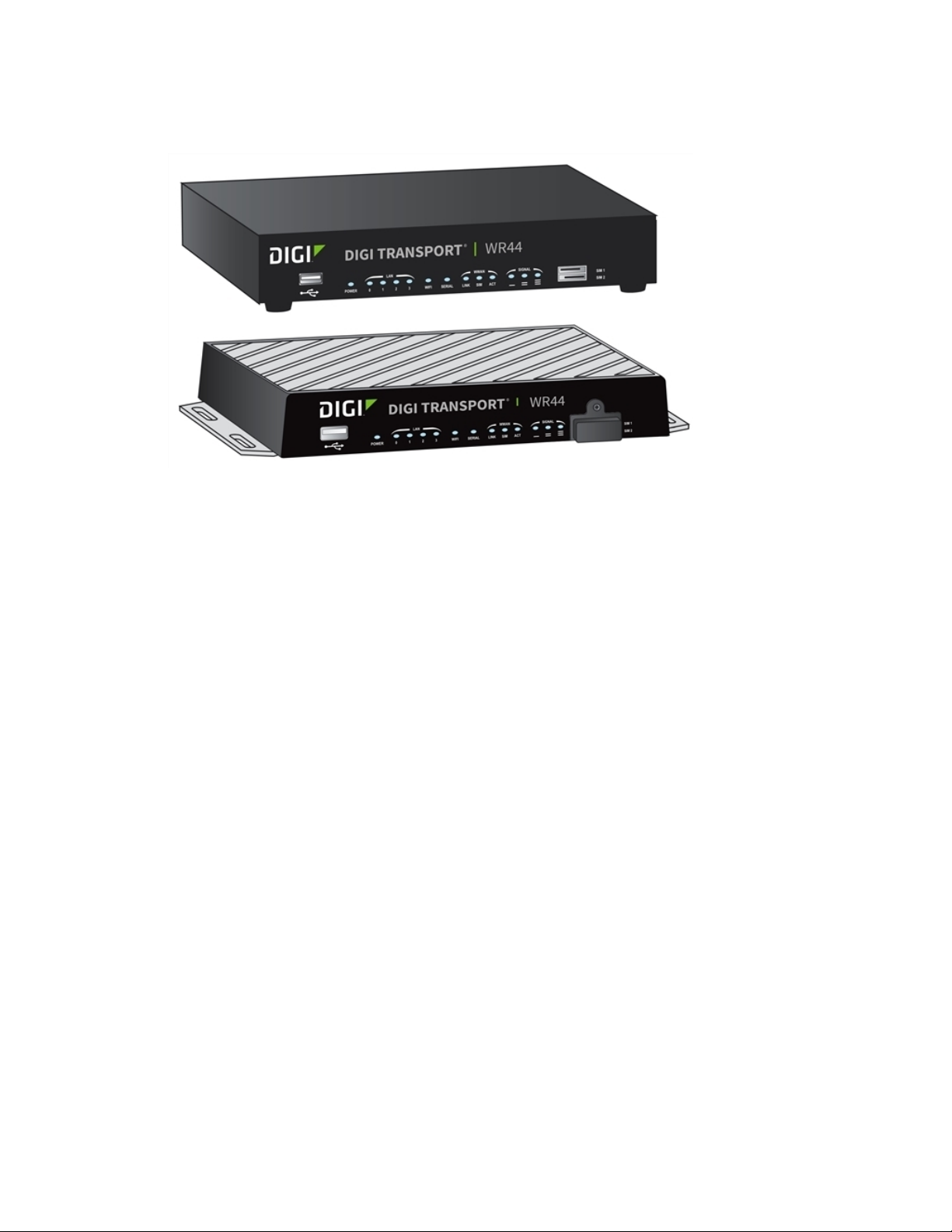
TransPort WR44 / WR44 R
The Digi TransPort WR44 cellular router is an all-in-one mobile communications solution with true
enterprise-class routing, security, and firewall. This multifunction cellular router features a flexible
design with integrated Wi-Fi access point, USB, serial, and 4-port Ethernet switch, as well as a variety
of configuration options including multiple serial ports (async or sync) and GPS or I/O telemetry
modules.
The Digi TransPort family offers an advanced routing, securityb and firewall feature set including
stateful inspection firewall and integrated VPN. Enterprise-class protocols incorporate BGP, OSPF,
and VRRP+, a patented technology built upon the popular VRRP failover standard providing true auto
sensing, auto failure and auto recovery of any line drop.
Digi TransPort WR44 is ideal for transportation and mobile applications. Flexible power options include
11-58 VDC barrel or molex connectors for direct integration into vehicle applications. Digi Remote
Manager™ provides easy setup, configuration, and maintenance of large installations of Digi TransPort
devices.
Digi TransPort® Routers User Guide
21
Page 22

Digi TransPort® routers TransPort WR44 RR
TransPort WR44 RR
Digi TransPort WR44 RR is a rugged enterprise-class cellular router designed for rail environments. Its
rail industry ratings, versatility, security features, and performance make it ideal for applications such
as Positive Train Control (PTC), wayside device communications, and on-board passenger Internet
access.
Digi TransPort WR44 RR provides a reliable primary high speed cellular network connection or can act
as a secure backup connection to the existing railroad network. It features a flexible communications
design with 3G/4G multicarrier GSM/CDMA cellular, plus integrated Wi-Fi a/ac/b/g/n access point,
serial, and 4-port Ethernet switch. It also features full on-board train certifications, including AREMA
C/H and EN50155. Communications interfaces include hardened connectors, including M12 for
Ethernet and serial, as well as TNC connectors for antenna connections.
Digi management solutions provide easy setup, configuration, and maintenance of large installations
of remote Digi TransPort devices. Digi Remote Manager offers web-based device management for
remote Digi cellular routers and gateways.
Digi TransPort® Routers User Guide
22
Page 23

Hardware features
TransPort WR11 hardware features 24
TransPort WR21 hardware features 35
TransPort WR31 hardware features 45
TransPort WR41 hardware features 64
TransPort WR44 / WR44 R hardware features 76
TransPort WR44 RR hardware features 91
Signal strength indicators 102
Antenna specifications for Wi-Fi 2.4 GHz modules 103
Digi TransPort® Routers User Guide
23
Page 24
Hardware features TransPort WR11 hardware features
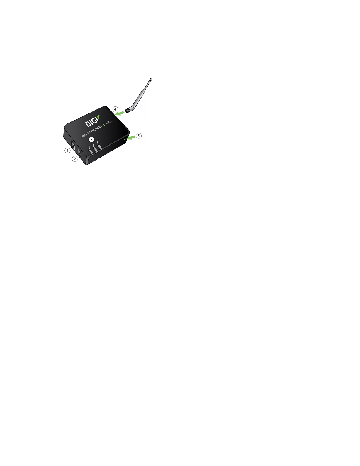
TransPort WR11 hardware features
TransPort WR11 EVDO model
1. LAN port: Connects the device to a 10/100 base-T Local Area Network (LAN). The port can
perform auto-sensing for speed and wiring, so it can accept straight-through or cross-over
cable connections.
2. Power connector: This locking power connector connects the device to a power source. The
connector should be inserted and rotated to lock in place. Center pin is positive.
3. LEDs:
n Service LED: Indicates the presence and level of cellular service running on the device.
Off: No cellular service
1 Blink: Device is running 1xRTT service
2 Blinks: Device is running EDVO Rev 0 service
3 Blinks: Device is running EDVO Rev A service
n Signal LED: Indicates strength of cellular signal.
Off: Poor or No signal. Place the device in a location where it gets a better
signal.
Amber: Fair
Green: Good
n Power LED
Off: No power
Green: TransPort device is powered
4. Cellular antenna connector: This SMA female connector connects the device’s primary
cellular antenna.
5. Reset button: Resets the router to factory defaults. See Reset the router to factory defaults.
Digi TransPort® Routers User Guide
24
Page 25

Hardware features TransPort WR11 hardware features
TransPort WR11 HSPA+ model
1. LAN port: Connects the device to a 10/100 base-T Local Area Network (LAN). The port can
perform auto-sensing for speed and wiring, so it can accept straight-through or cross-over
cable connections.
2. Power connector: This locking power connector connects the device to a power source. The
connector should be inserted and rotated to lock in place. Center pin is positive.
3. LEDs:
n SERVICE LED: Indicates the presence and level of cellular service running on the device.
Off: No cellular service
1 Blink: GPRS mode
2 Blinks: EDGE mode
3 Blinks: UMTS mode
4 Blinks: HSDPA mode
5 Blinks: HSUPA mode
n SIGNAL LED: Indicates strength of cellular signal.
Off: Poor or No signal. Place the device in a location where it gets a better
signal.
Amber: Fair
Green: Good
n POWER LED:
Off: No power
Green: TransPort device is powered
4. SIM door: Encloses the SIM sockets. The SIM door must be removed to install the SIM cards For
installation details, refer to the Quick Start Guide that came with your device.
Note To remove the SIM door, hold the device on a flat surface and using a screwdriver, firmly
pull the cover straight up.
5. Cellular antenna connector: This SMA female connector connects the device’s primary
cellular antenna.
6. Reset button:Resets the router to factory defaults. See Reset the router to factory defaults.
7. SIM Sockets: SIM 1 and SIM 2 are for use with the SIMs.
Digi TransPort® Routers User Guide
25
Page 26

Hardware features TransPort WR11 hardware features
TransPort WR11 LTE-MIMO
1. LAN port: Connects the device to a 10/100 base-T Local Area Network (LAN). The port can
perform auto-sensing for speed and wiring, so it can accept straight-through or cross-over
cable connections.
2. Power connector: This locking power connector connects the device to a power source. The
connector should be inserted and rotated to lock in place. Center pin is positive.
3. LEDs:
n SERVICE LED: Indicates the presence and level of cellular service running on the device.
Off: No cellular service
1 Blink: GPRS mode
2 Blinks: EDGE mode
3 Blinks: UMTS mode
4 Blinks: HSDPA mode
5 Blinks: HSUPA mode
6 Blinks: LTE mode
n SIGNAL LED: Indicates strength of cellular signal.
Off: Poor or No signal. Place the device in a location where it gets a better
signal.
Amber: Fair
Green: Good
n POWERLED:
Off: No power
Green: TransPort device is powered
Digi TransPort® Routers User Guide
26
Page 27

Hardware features TransPort WR11 hardware features
4. SIM door: Encloses the SIM sockets. The SIM door must be opened to install the SIM cards. For
installation details, refer to the Quick Start Guide that came with your device.
Note To open the SIM door, slide the SIM door out using your finger.
5. Reset button:Resets the router to factory defaults. See Reset the router to factory defaults.
6. SIM sockets: SIM 1 and SIM 2 are for use with the SIMs.
7. Primary LTE antenna connector: This SMA female connector connects the device’s primary
cellular antenna.
8. Secondary LTE antenna connector: This SMA female connector connects the device’s
secondary cellular antenna.
TransPort WR11 XT
1. LAN port: Connects the device to a 10/100 base-T Local Area Network (LAN). The port can
perform auto-sensing for speed and wiring, so it can accept straight-through or cross-over
cable connections.
2. Power connector: This locking power connector connects the device to a power source. The
connector should be inserted and rotated to lock in place. Center pin is positive.
Digi TransPort® Routers User Guide
27
Page 28

Hardware features TransPort WR11 hardware features
3. LEDs:
n SERVICE LED: Indicates the presence and level of cellular service running on the device.
Off: No cellular service
1 Blink: GPRS mode
2 Blinks: EDGE mode
3 Blinks: UMTS mode
4 Blinks: HSDPA mode
5 Blinks: HSUPA mode
6 Blinks: LTE mode
n SIGNAL LED: Indicates strength of cellular signal.
Off: Poor or No signal. Place the device in a location where it gets a better
signal.
Amber: Fair
Green: Good
n POWER LED:
Off: No power
Green: TransPort device is powered
4. SIM door: Encloses the SIM sockets. The SIM door must be opened to install the SIM cards. For
installation details, refer to the Quick Start Guide that came with your device.
5. Reset button: Resets the router to factory defaults. See Reset the router to factory defaults.
6. SIM sockets: SIM 1 and SIM 2 are for use with the SIMs. Insert SIM cards with the notch facing
the bottom-right corner of the device. If you are using one SIM card only, insert it in the SIM 1
slot.
7. Primary cellular antenna connector: This SMA female connector connects the device’s
primary cellular antenna.
8. Secondary cellular antenna connector: This SMA female connector connects the device’s
secondary cellular antenna.
Digi TransPort® Routers User Guide
28
Page 29

Hardware features TransPort WR11 hardware features
TransPort WR11 accessories
A variety of accessories are available for TransPort products. For the current list of accessories and
their Digi part numbers, go to the TransPort WR11 Part Numbers and Accessories page.
Digi TransPort® Routers User Guide
29
Page 30

Hardware features TransPort WR11 hardware features
TransPort WR11 hardware specifications
TransPort WR11 specifications
TransPort WR11 XT specifications
Digi TransPort® Routers User Guide
30
Page 31

Hardware features TransPort WR11 hardware features
Regulatory and safety statements
RF exposure statement
In order to comply with RF exposure limits established in the ANSI C95.1 standards, the distance
between the antenna or antennas and the user should not be less than 20 cm.
FCC Part 15 Class B
Radio Frequency Interference (RFI) (FCC 15.105)
This device has been tested and found to comply with the limits for Class B digital devices pursuant to
Part 15 Subpart B, of the FCC rules. These limits are designed to provide reasonable protection
against harmful interference in a residential environment. This equipment generates, uses, and can
radiate radio frequency energy, and if not installed and used in accordance with the instruction
manual, may cause harmful interference to radio communications. However, there is no guarantee
that interference will not occur in a particular installation. If this equipment does cause harmful
interference to radio or television reception, which can be determined by turning the equipment off
and on, the user is encouraged to try and correct the interference by one or more of the following
measures:
Reorient or relocate the receiving antenna. Increase the separation between the equipment and
receiver. Connect the equipment into an outlet on a circuit different from that to which the receiver is
connected. Consult the dealer or an experienced radio/TV technician for help.
Labeling Requirements (FCC 15.19)
This device complies with Part 15 of FCC rules. Operation is subject to the following two conditions: (1)
this device may not cause harmful interference, and (2) this device must accept any interference
received, including interference that may cause undesired operation.
If the FCC ID is not visible when installed inside another device, then the outside of the device into
which the module is installed must also display a label referring to the enclosed module FCC ID.
Modifications (FCC 15.21)
Changes or modifications to this equipment not expressly approved by Digi may void the user’s
authority to operate this equipment.
TransPort WR11 EU Declaration of Conformity
Digi has issued Declarations of Conformity for the Digi TransPort WR11 concerning emissions, EMC,
and safety. For more information, see Digi government agency certifications page.
Important note
Digi customers assume full responsibility for learning and meeting the required guidelines for each
country in their distribution market. Refer to the radio regulatory agency in the desired countries of
operation for more information.
CE mark (Europe)
The Digi TransPort WR11 is certified for use in several European countries. For information, visit Digi
government agency certifications page.
If the Digi TransPort WR11 is incorporated into a product, the manufacturer must ensure compliance
of the final product with articles 3.1a and 3.1b of the RE Directive (Radio Equipment Directive). A
Digi TransPort® Routers User Guide
31
Page 32

Hardware features TransPort WR11 hardware features
Declaration of Conformity must be issued for each of these standards and kept on file as described in
the RE Directive (Radio Equipment Directive).
Furthermore, the manufacturer must maintain a copy of the Digi TransPort WR11 user manual
documentation and ensure the final product does not exceed the specified power ratings, antenna
specifications, and/or installation requirements as specified in the user manual. If any of these
specifications are exceeded in the final product, a submission must be made to a notified body for
compliance testing to all required standards.
OEM labeling requirements
The “CE” marking must be affixed to a visible location on the OEM product.
CE labeling requirements
The CE mark shall consist of the initials “CE” taking the following form:
n If the CE marking is reduced or enlarged, the proportions given in the above graduated
drawing must be respected.
n The CE marking must have a height of at least 5 mm except where this is not possible on
account of the nature of the apparatus.
n The CE marking must be affixed visibly, legibly, and indelibly.
Maximum power and frequency bands
Max power Frequencies
2 W Cellular 850 and 900 MHZ bands
1 W Cellular 850 and 900 MHZ bands
Innovation, Science, and Economic Development Canada (IC) certifications
This digital apparatus does not exceed the Class B limits for radio noise emissions from digital
apparatus set out in the Radio Interference Regulations of the Canadian Department of
Digi TransPort® Routers User Guide
32
Page 33

Hardware features TransPort WR11 hardware features
Communications.
Le present appareil numerique n’emet pas de bruits radioelectriques depassant les limites applicables
aux appareils numeriques de la class B prescrites dans le Reglement sur le brouillage radioelectrique
edicte par le ministere des Communications du Canada.
Restricted Access Location notice for TransPort WR11 XT
Because of the hot metal surface of the enclosure, installations with operating temperatures greater
than 122 F (50 C) must be limited to Restricted Access Locations accessible only to trained service
personnel.
Safety notices
1. Please read all instructions before installing and powering the router. You should keep these
instructions in a safe place for future reference.
2. If the power supply shows signs of damage or malfunction, stop using it immediately, turn off
the power and disconnect the power supply before contacting your supplier for a repair or
replacement.
3. Changes or modifications not expressly approved by the party responsible for compliance could
void the user’s authority to operate the equipment. Use only the accessories, attachments,
and power supplies provided by the manufacturer-connecting non-approved antennas or
power supplies may damage the router, cause interference or create an electric shock hazard,
and will void the warranty.
4. Do not attempt to repair the product. The router contains no electronic components that can
be serviced or replaced by the user. Any attempt to service or repair the router by the user will
void the product warranty.
5. The TransPort WR11 is designed for indoor use. Use it in an environment suitable for
computers and other electronic equipment.
6. Ports that are capable of connecting to other apparatus are defined as SELV ports. To ensure
conformity with IEC60950 ensure that these ports are only connected to ports of the same
type on other apparatus.
Special notes on safety for wireless routers
Digi International products are designed to the highest standards of safety and
international standards compliance for the markets in which they are sold. However,
cellular-based products contain radio devices which require specific consideration.
Please take the time to read and understand the following guidance. Digi International
assumes no liability for an end user’s failure to comply with these precautions.
Digi TransPort® Routers User Guide
33
Page 34

Hardware features TransPort WR11 hardware features
Wireless routers incorporate a wireless radio module. Users should ensure that the
antenna(s) is (are) positioned at least 1 meter away from themselves and other persons
in normal operation.
When in a hospital or other health care facility, observe the restrictions on the use of
mobile phones. Do not use the router in areas where guidelines posted in sensitive
areas instruct users to switch off mobile phones. Medical equipment may be sensitive to
RF energy.
The operation of cardiac pacemakers, other implanted medical equipment and hearing
aids can be affected by interference from cellular terminals such as the wireless routers
when places close to the device. If in doubt about potential danger, contact the
physician or the manufacturer of the device to verify that the equipment is properly
shielded. Pacemaker patients are advised to keep the wireless router away from the
pacemaker while it is on.
Wireless routers must NOT be operated on aircraft. The operation of wireless
appliances in an aircraft is forbidden to prevent interference with communications
systems. Failure to observe these instructions may lead to the suspension or denial of
cellular services to the offender, legal action, or both.
As with any electrical equipment, do not operate the router in the presence of
flammable gases, fumes or potentially explosive atmospheres. Do not use radio devices
anywhere that blasting operations occur.
Wireless routers receive and transmit radio frequency energy when power is on.
Interference can occur when using the router close to TV sets, radios, computers or
inadequately shielded equipment. Follow any special regulations and always power off
your router wherever forbidden or when it may cause interference or danger.
SOS IMPORTANT!
cannot be guaranteed to connect in all possible conditions. Therefore, never rely solely
upon any wireless device for life critical communications.
WARNING! For environments where the temperature is 55° C or above, this
device must be installed in a restricted access area.
Wireless routers operate using radio signals and cellular networks
Product Disposal Instructions
The WEEE (Waste Electrical and Electronic Equipment: 2002/96/EC) directive has been
introduced to ensure that electrical/ electronic products are recycled using the best
available recovery techniques to minimize the impact on the environment.
This product contains high quality materials and components which can be recycled. At
the end of its life this product MUST NOT be mixed with other commercial waste for
disposal. Check with the terms and conditions of your supplier for disposal information.
Digi International Ltd WEEE Registration number: WEE/HF1515VU
Digi TransPort® Routers User Guide
34
Page 35

Hardware features TransPort WR21 hardware features
TransPort WR21 hardware features
TransPort WR21 front panel
1. SIM/R-UIM sockets (SIM card models only): SIM 1 and SIM 2 are for use with SIMs or R-UIMs
(Removable User Identification Modules).
2. POWER LED:
n Off: No power
n Green: TransPort device is powered
3. SERVICE LED:
n Off: No WWAN network connection
n Green: WWAN network connection
n Flashing: WWAN traffic being transmitted or received
4. WWAN (Wireless Network) LED: Indicates the presence and level of cellular service running on
the device.
n Off: No cellular service
n 1 Blink: GPRS mode
n 2 Blinks: EDGE mode
n 3 Blinks: UMTS mode
n 4 Blinks: HSDPA mode
n 5 Blinks: HSUPA mode
n 6 Blinks: LTE mode
5. SIGNAL LED: Indicate strength of cellular signal.
n 3 LEDs: Excellent
n 2 LEDs: Good
n 1 LED: Fair
n 0 LEDs: Poor or No signal
6. Reset button: Returns the router to its factory default settings. See Reset the router to
factory defaults.
7. USB host connector: Connects compatible USB 2.0 client devices such as memory sticks, and
serial adapters. The total current available to power USB devices is 0.5 A.
Digi TransPort® Routers User Guide
35
Page 36

Hardware features TransPort WR21 hardware features
TransPort WR21 rear panel features
1. Secondary cellular (WWAN) antenna connector: This SMA female connector connects the
router’s secondary cellular antenna. It is highly recommended to use the secondary antenna
for diversity. In most circumstances, dual antennas provide improved signal strength and
better performance.
2. LAN 0 port: This RJ45 port connects the router to a 10/100 base-TLAN. The port is auto-
sensing for speed and wiring (straight-through or cross-over).
3. LAN 1 port (optional): This RJ45 port connects the router to a 10/100 base-TLAN. The port is
auto- sensing for speed and wiring (straight-through or cross-over).
4. Serial 0 port: This DB9 port provides an asynchronous RS232 (RS485 optional) serial port with
optional RS422/485 support for connecting the router to a compatible serial device. This is a
DCE serial port and allows CLI access to the device by default; the baud rate is 115200. For a
pinout, see TransPort WR21 serial pinout.
5. Power connector: This connector connects the router to a power source using either the
supplied power supply or DC power cord. Secure the barrel plug connector by rotating it by 90
degrees once installed into the Digi TransPort router. Center pin is positive.
6. Primary cellular (WWAN) antenna connector: This SMA female connector connects the
router’s primary cellular antenna.
7. Power cord input (terminal block variant): This socket connects the router to an alternative
power source.
Digi TransPort® Routers User Guide
36
Page 37

Hardware features TransPort WR21 hardware features
Reset the TransPort WR21
1. Turn the router on and wait 15 seconds for the router to complete its initialization process.
2. Press and hold the reset button for 5 seconds. The router automatically reboots and displays a
pattern of alternating LEDs flashing followed by the normal boot sequence.
CAUTION! Do not remove power from the router during this operation, as corruption
of the flash memory may occur.
Digi TransPort® Routers User Guide
37
Page 38

Hardware features TransPort WR21 hardware features
TransPort WR21 serial pinout
Note that all TransPort serial ports are DCE.
RS232 pinout
Pin # Direction RS232 DCE Description
1 Out DCD Data Carrier Detect
2 Out RXD Receive Data
3 In TXD Transmit Data
4 In DTR Data Terminal Ready
5 N/A GND Ground
6 Out DSR Data Set Ready
7 In RTS Ready To Send
8 Out CTS Clear To Send
9 Out RI Ring Indicate
RS422/RS485 pinout
Pin # Direction RS422/ RS485 Description
1 Out CTS- Clear To Send -
2 Out RD+ Receive Data +
3 In TD+ Transmit Data+
4 In RTS B RTS- Ready To Send -
5 N/A GND Ground
Digi TransPort® Routers User Guide
38
Page 39

Hardware features TransPort WR21 hardware features
Pin # Direction RS422/ RS485 Description
6 Out RD- Receive Data -
7 In RTS+ Ready To Send +
8 Out CTS+ Clear To Send +
9 In TD- Transmit -
Notes
n For true RS485 mode (2-wire half-duplex mode), the TD+ and RD+ pair and TD- and RD- pair
should be connected together.
n The CTS and RTS signals are optional and not normally needed for RS485.
Digi TransPort® Routers User Guide
39
Page 40

Hardware features TransPort WR21 hardware features
TransPort WR21 accessories
A variety of accessories are available for TransPort products. For the current list of accessories and
their Digi part numbers, go to the TransPort WR21 Part Numbers and Accessories page.
Digi TransPort® Routers User Guide
40
Page 41

Hardware features TransPort WR21 hardware features
TransPort WR21 hardware specifications
TransPort WR21 hardware specifications
Regulatory and safety statements
RF exposure statement
In order to comply with RF exposure limits established in the ANSI C95.1 standards, the distance
between the antenna or antennas and the user should not be less than 20 cm.
FCC Part 15 Class B
Radio Frequency Interference (RFI) (FCC 15.105)
This device has been tested and found to comply with the limits for Class B digital devices pursuant to
Part 15 Subpart B, of the FCC rules. These limits are designed to provide reasonable protection
against harmful interference in a residential environment. This equipment generates, uses, and can
radiate radio frequency energy, and if not installed and used in accordance with the instruction
manual, may cause harmful interference to radio communications. However, there is no guarantee
that interference will not occur in a particular installation. If this equipment does cause harmful
interference to radio or television reception, which can be determined by turning the equipment off
and on, the user is encouraged to try and correct the interference by one or more of the following
measures:
Reorient or relocate the receiving antenna. Increase the separation between the equipment and
receiver. Connect the equipment into an outlet on a circuit different from that to which the receiver is
connected. Consult the dealer or an experienced radio/TV technician for help.
Labeling Requirements (FCC 15.19)
This device complies with Part 15 of FCC rules. Operation is subject to the following two conditions: (1)
this device may not cause harmful interference, and (2) this device must accept any interference
received, including interference that may cause undesired operation.
If the FCC ID is not visible when installed inside another device, then the outside of the device into
which the module is installed must also display a label referring to the enclosed module FCC ID.
Modifications (FCC 15.21)
Changes or modifications to this equipment not expressly approved by Digi may void the user’s
authority to operate this equipment.
TransPort WR21 EU Declaration of Conformity
Digi has issued Declarations of Conformity for the Digi TransPort WR21 concerning emissions, EMC,
and safety. For more information, see Digi government agency certifications page.
Important note
Digi customers assume full responsibility for learning and meeting the required guidelines for each
country in their distribution market. Refer to the radio regulatory agency in the desired countries of
operation for more information.
Digi TransPort® Routers User Guide
41
Page 42

Hardware features TransPort WR21 hardware features
CE mark (Europe)
The Digi TransPort WR21 is certified for use in several European countries. For information, visit Digi
government agency certifications page.
If the Digi TransPort WR21 is incorporated into a product, the manufacturer must ensure compliance
of the final product with articles 3.1a and 3.1b of the RE Directive (Radio Equipment Directive). A
Declaration of Conformity must be issued for each of these standards and kept on file as described in
the RE Directive (Radio Equipment Directive).
Furthermore, the manufacturer must maintain a copy of the Digi TransPort WR21 user manual
documentation and ensure the final product does not exceed the specified power ratings, antenna
specifications, and/or installation requirements as specified in the user manual. If any of these
specifications are exceeded in the final product, a submission must be made to a notified body for
compliance testing to all required standards.
OEM labeling requirements
The “CE” marking must be affixed to a visible location on the OEM product.
CE labeling requirements
The CE mark shall consist of the initials “CE” taking the following form:
n If the CE marking is reduced or enlarged, the proportions given in the above graduated
drawing must be respected.
n The CE marking must have a height of at least 5 mm except where this is not possible on
account of the nature of the apparatus.
n The CE marking must be affixed visibly, legibly, and indelibly.
Maximum power and frequency bands
Digi TransPort® Routers User Guide
42
Page 43

Hardware features TransPort WR21 hardware features
Max power Frequencies
2 W Cellular 850 and 900 MHz bands
1 W Cellular 1800 and 1900 MHz Bands
200 mW Cellular @450 MHz Band
Innovation, Science, and Economic Development Canada (IC) certifications
This digital apparatus does not exceed the Class B limits for radio noise emissions from digital
apparatus set out in the Radio Interference Regulations of the Canadian Department of
Communications.
Le present appareil numerique n’emet pas de bruits radioelectriques depassant les limites applicables
aux appareils numeriques de la class B prescrites dans le Reglement sur le brouillage radioelectrique
edicte par le ministere des Communications du Canada.
Hazardous Location installation information for TransPort WR21
For Hazardous Location installation, see the TransPort WR21 Hazardous Location User Guide (Digi part
number 90001532).
Safety notices
1. Please read all instructions before installing and powering the router. You should keep these
instructions in a safe place for future reference.
2. If the power supply shows signs of damage or malfunction, stop using it immediately, turn off
the power and disconnect the power supply before contacting your supplier for a repair or
replacement.
3. Changes or modifications not expressly approved by the party responsible for compliance could
void the user’s authority to operate the equipment. Use only the accessories, attachments,
and power supplies provided by the manufacturer-connecting non-approved antennas or
power supplies may damage the router, cause interference or create an electric shock hazard,
and will void the warranty.
4. Do not attempt to repair the product. The router contains no electronic components that can
be serviced or replaced by the user. Any attempt to service or repair the router by the user will
void the product warranty.
5. The TransPort WR21 is designed for indoor use. Use it in an environment suitable for
computers and other electronic equipment.
6. Ports that are capable of connecting to other apparatus are defined as SELV ports. To ensure
conformity with IEC60950 ensure that these ports are only connected to ports of the same
type on other apparatus.
Special notes on safety for wireless routers
Digi International products are designed to the highest standards of safety and
international standards compliance for the markets in which they are sold. However,
cellular-based products contain radio devices which require specific consideration.
Please take the time to read and understand the following guidance. Digi International
assumes no liability for an end user’s failure to comply with these precautions.
Digi TransPort® Routers User Guide
43
Page 44

Hardware features TransPort WR21 hardware features
Wireless routers incorporate a wireless radio module. Users should ensure that the
antenna(s) is (are) positioned at least 1 meter away from themselves and other persons
in normal operation.
When in a hospital or other health care facility, observe the restrictions on the use of
mobile phones. Do not use the router in areas where guidelines posted in sensitive
areas instruct users to switch off mobile phones. Medical equipment may be sensitive to
RF energy.
The operation of cardiac pacemakers, other implanted medical equipment and hearing
aids can be affected by interference from cellular terminals such as the wireless routers
when places close to the device. If in doubt about potential danger, contact the
physician or the manufacturer of the device to verify that the equipment is properly
shielded. Pacemaker patients are advised to keep the wireless router away from the
pacemaker while it is on.
Wireless routers must NOT be operated on aircraft. The operation of wireless
appliances in an aircraft is forbidden to prevent interference with communications
systems. Failure to observe these instructions may lead to the suspension or denial of
cellular services to the offender, legal action, or both.
As with any electrical equipment, do not operate the router in the presence of
flammable gases, fumes or potentially explosive atmospheres. Do not use radio devices
anywhere that blasting operations occur.
Wireless routers receive and transmit radio frequency energy when power is on.
Interference can occur when using the router close to TV sets, radios, computers or
inadequately shielded equipment. Follow any special regulations and always power off
your router wherever forbidden or when it may cause interference or danger.
SOS IMPORTANT!
cannot be guaranteed to connect in all possible conditions. Therefore, never rely solely
upon any wireless device for life critical communications.
WARNING! For environments where the temperature is 55° C or above, this
device must be installed in a restricted access area.
Wireless routers operate using radio signals and cellular networks
Product Disposal Instruction
The WEEE (Waste Electrical and Electronic Equipment: 2002/96/EC) directive has been
introduced to ensure that electrical/ electronic products are recycled using the best
available recovery techniques to minimize the impact on the environment.
This product contains high quality materials and components which can be recycled. At
the end of its life this product MUST NOT be mixed with other commercial waste for
disposal. Check with the terms and conditions of your supplier for disposal information.
Digi International Ltd WEEE Registration number: WEE/HF1515VU
Digi TransPort® Routers User Guide
44
Page 45

Hardware features TransPort WR31 hardware features
TransPort WR31 hardware features
1. SIM card slot cover: On the underside of the router. Remove and replace with a Phillips-head
screwdriver.
2. SIM 1 and SIM 2 card slots: On the underside of the router. SIM 1 and SIM 2 are for use with .
When inserting the SIM card(s) into SIM sockets, SIM 1 is toward the middle of the router, and
SIM 2 is toward the outside of the router. In both cases, the end of the SIM card with the
chamfered corner should be inserted first.
3. LAN 0 port: This RJ45 port connects the router to a 10/100 base-TLAN. The port is auto-
sensing for speed and wiring (straight-through or cross-over).
4. LAN 1 port: This RJ45 port connects the router to a 10/100 base-TLAN. The port is auto-
sensing for speed and wiring (straight-through or cross-over).
5. USB host connector: Connects compatible USB 2.0 client devices such as memory sticks, and
serial adapters. The total current available to power USB devices is 0.5 A.
WARNING! The USB port is for use in a normal location only, not a hazardous
location.
6. Reset button: Returns the router to its factory default settings. See Reset the router to
factory defaults.
Digi TransPort® Routers User Guide
45
Page 46

Hardware features TransPort WR31 hardware features
7. Serial connector: This DB9 port provides an asynchronous RS232 (RS485 optional) serial port
with optional RS422/485 support to connect the router to a compatible serial device. This is a
DCE serial port and allows CLI access to the device by default; the default serial baud rate is
115200. For a pinout, see TransPort WR31 serial pinout.
8. Power connector: A pluggable connector that connects the router to a power source using
either the separately available power supply: Digi part number 76000736, or a DIN rail power
supply.
9. WWAN primary connector: This SMA male connector connects the router’s primary cellular
antenna.
10. WWAN secondary connector: This SMA male connector connects the router’s secondary
cellular antenna. For multiple-input and multiple-output (MIMO), both cellular antennas are
needed for downloading data.
Not shown: GPS antenna connector (GPS models only): An SMA male connector that
connects the router’s GPS antenna.
11. LEDs: Indicate startup states and status for various signals and services:
n POWER LED:
Off: No power
Green: TransPort device is powered
n SERVICE LED:
Off: No WWAN network connection
Green: WWAN network connection
Flashing: WWAN traffic being transmitted or received
n WWAN LED: Indicates the presence and level of cellular service running on the device.
Off: No cellular service
1 Blink: GPRS mode
2 Blinks: EDGE mode
3 Blinks: UMTS mode
4 Blinks: HSDPA mode
5 Blinks: HSUPA mode
6 Blinks: LTE mode
n SIGNAL LEDs: Indicate strength of cellular signal.
3 LEDs: Excellent
2 LEDs: Good
1 LED: Fair
0 LEDs: Poor or No signal
n SYSTEM LED: Reserved for user-defined functions.
12. Earth ground
Digi TransPort® Routers User Guide
46
Page 47

Hardware features TransPort WR31 hardware features
13. Digital/analog I/O connector: An input/output connector with two digital input/output
connections, and a single analog input connection. For more information and wiring diagrams
see TransPort WR31 digital and analog inputs and outputs.
Digi TransPort® Routers User Guide
47
Page 48

Hardware features TransPort WR31 hardware features
TransPort WR31 hardware specifications
Digi TransPort WR31 specifications
Digi TransPort® Routers User Guide
48
Page 49

Hardware features TransPort WR31 hardware features
TransPort WR31 accessories
A variety of accessories are available for TransPort products. For the current list of accessories and
their Digi part numbers, go to the TransPort WR31 Part Numbers and Accessories page.
Digi TransPort® Routers User Guide
49
Page 50

Hardware features TransPort WR31 hardware features
TransPort WR31 mounting options
You can mount the TransPort WR31 on a DIN rail, directly to a wall, or in a NEMA enclosure. For DIN
Rail mounting, purchase the WR31 DIN Rail Mounting Bracket (Digi part number 76000977). For wallmounting or NEMA enclosure installation, purchase the TransPort WR31 Wall Mount Bracket (Digi part
number 76000966) and NEMA enclosure equipment, such as the NEMA enclosure, mounting plate,
special cabling, and cable glands.
Digi TransPort® Routers User Guide
50
Page 51

Hardware features TransPort WR31 hardware features
Hazardous Location installation
For information on installing the TransPort WR31 in a Hazardous Location environment, see the Digi
TransPort WR31 Hazardous Locations User Guide.
Digi TransPort® Routers User Guide
51
Page 52

Hardware features TransPort WR31 hardware features
TransPort WR31 serial pinout
Note that all TransPort serial ports are DCE.
RS232 pinout
Pin # Direction RS232 DCE Description
1 Out DCD Data Carrier Detect
2 Out RXD Receive Data
3 In TXD Transmit Data
4 In DTR Data Terminal Ready
5 N/A GND Ground
6 Out DSR Data Set Ready
7 In RTS Ready To Send
8 Out CTS Clear To Send
9 Out RI Ring Indicate
Digi TransPort® Routers User Guide
52
Page 53

Hardware features TransPort WR31 hardware features
RS422/RS485 pinout
Pin # Direction RS422/ RS485 Description
1 Out CTS- Clear To Send -
2 Out RD+ Receive Data +
3 In TD+ Transmit Data+
4 In RTS_B RTS- Ready To Send -
5 N/A GND Ground
6 Out RD- Receive Data -
7 In RTS+ Ready To Send +
8 Out CTS+ Clear To Send +
9 In TD- Transmit -
Notes
n For true RS485 mode (2-wire half-duplex mode), the TD+ and RD+ pair and TD- and RD- pair
should be connected together.
n The CTS and RTS signals are optional normally not needed for RS485.
Digi TransPort® Routers User Guide
53
Page 54

Hardware features TransPort WR31 hardware features
TransPort WR31 digital and analog inputs and outputs
The TransPort WR31 has an input/output connector with two digital input/output connections,
and a single analog input connection.
I/O connector pin assignments
The figure and table show the I/O connector, pin assignments, and the signals for each pin.
Pin# Symbol Description
5 AIN0 Analog Input 0
4 AGND Analog Return
3 DIO0 Digital I/O 0
2 GND Digital Return
1 DIO1 Digital I/O 1
Digi TransPort® Routers User Guide
54
Page 55

Hardware features TransPort WR31 hardware features
TransPort WR31 digital input/output: representative circuit
TransPort WR31 analog input: representative circuit
Digi TransPort® Routers User Guide
55
Page 56

Hardware features TransPort WR31 hardware features
Example digital and analog I/O wiring
Digital input with pullup
Digital input without pullup
Note that input is HIGH when the contact is CLOSED.
Digital output
The wiring diagram assumes a current-limiting resistor provided by installation or connected device is
in use.
Digi TransPort® Routers User Guide
56
Page 57

Hardware features TransPort WR31 hardware features
Analog input, 4-20mA input mode
Analog input, 0-10V input mode
Digi TransPort® Routers User Guide
57
Page 58

Hardware features TransPort WR31 hardware features
Digital and analog I/O specifications
Digital I/O specifications
Specification Min Nom Max Units
Rated Input Voltage -0.2 30 V
Rated Input Current -1.0 200 mA
Pull-Up Resistance 10 k Ohms
Digital input specifications
n This input is a non-inverting Schmitt-trigger input.
n The default state at power-up with no voltage applied is LOW.
Specification Min Nom Max Units
+ Threshold .. 1.6 .. V
- Threshold .. 1.0 .. V
Input impedance .. 1 M .. Ohms
Digital output
n This output is an open-collector, sinking driver output.
n The default state at power-up is off.
Specification Min Nom Max Units
Sink Current .. .. 200 mA
Pull-up Voltage 3 V
Analog input specifications
Specification Min Nom Max Units
Resolution .. .. 12 BITS
Accuracy .. .. 0.2 %
Rated Input Voltage -0.2 30 V
Rated Input Current 0 40 mA
Digi TransPort® Routers User Guide
58
Page 59

Hardware features TransPort WR31 hardware features
Voltage input mode (default)
Specification Min Nom Max Units
Input Voltage -0.2 .. 10.25 V
Input Impedance .. 291 K .. Ohms
Current loop mode
Specification Min Nom Max Units
Minimum Input Voltage .. 2 .. V
Load Resistance .. 200 .. Ohms
Digi TransPort® Routers User Guide
59
Page 60

Hardware features TransPort WR31 hardware features
Regulatory and safety statements
RF exposure statement
In order to comply with RF exposure limits established in the ANSI C95.1 standards, the distance
between the antenna or antennas and the user should not be less than 20 cm.
FCC Part 15 Class B
Radio Frequency Interference (RFI) (FCC 15.105)
This device has been tested and found to comply with the limits for Class B digital devices pursuant to
Part 15 Subpart B, of the FCC rules. These limits are designed to provide reasonable protection
against harmful interference in a residential environment. This equipment generates, uses, and can
radiate radio frequency energy, and if not installed and used in accordance with the instruction
manual, may cause harmful interference to radio communications. However, there is no guarantee
that interference will not occur in a particular installation. If this equipment does cause harmful
interference to radio or television reception, which can be determined by turning the equipment off
and on, the user is encouraged to try and correct the interference by one or more of the following
measures:
Reorient or relocate the receiving antenna. Increase the separation between the equipment and
receiver. Connect the equipment into an outlet on a circuit different from that to which the receiver is
connected. Consult the dealer or an experienced radio/TV technician for help.
Labeling Requirements (FCC 15.19)
This device complies with Part 15 of FCC rules. Operation is subject to the following two conditions: (1)
this device may not cause harmful interference, and (2) this device must accept any interference
received, including interference that may cause undesired operation.
If the FCC ID is not visible when installed inside another device, then the outside of the device into
which the module is installed must also display a label referring to the enclosed module FCC ID.
Modifications (FCC 15.21)
Changes or modifications to this equipment not expressly approved by Digi may void the user’s
authority to operate this equipment.
TransPort WR31 EU Declaration of Conformity
Digi has issued Declarations of Conformity for the Digi TransPort WR31 concerning emissions, EMC,
and safety. For more information, see Digi government agency certifications page.
Important note
Digi customers assume full responsibility for learning and meeting the required guidelines for each
country in their distribution market. Refer to the radio regulatory agency in the desired countries of
operation for more information.
CE mark (Europe)
The Digi TransPort WR31 is certified for use in several European countries. For information, visit Digi
government agency certifications page.
If the Digi TransPort WR31 is incorporated into a product, the manufacturer must ensure compliance
of the final product with articles 3.1a and 3.1b of the RE Directive (Radio Equipment Directive). A
Digi TransPort® Routers User Guide
60
Page 61

Hardware features TransPort WR31 hardware features
Declaration of Conformity must be issued for each of these standards and kept on file as described in
the RE Directive (Radio Equipment Directive).
Furthermore, the manufacturer must maintain a copy of the Digi TransPort WR31 user manual
documentation and ensure the final product does not exceed the specified power ratings, antenna
specifications, and/or installation requirements as specified in the user manual. If any of these
specifications are exceeded in the final product, a submission must be made to a notified body for
compliance testing to all required standards.
OEM labeling requirements
The “CE” marking must be affixed to a visible location on the OEM product.
CE labeling requirements
The CE mark shall consist of the initials “CE” taking the following form:
n If the CE marking is reduced or enlarged, the proportions given in the above graduated
drawing must be respected.
n The CE marking must have a height of at least 5 mm except where this is not possible on
account of the nature of the apparatus.
n The CE marking must be affixed visibly, legibly, and indelibly.
Maximum power and frequency bands
Max power Frequencies
2 W Cellular 850 and 900 MHz bands
1 W Cellular 1800 and 1900 MHz bands
200 mW Cellular @450 MHz band
Digi TransPort® Routers User Guide
61
Page 62

Hardware features TransPort WR31 hardware features
Innovation, Science, and Economic Development Canada (IC) certifications
This digital apparatus does not exceed the Class B limits for radio noise emissions from digital
apparatus set out in the Radio Interference Regulations of the Canadian Department of
Communications.
Le present appareil numerique n’emet pas de bruits radioelectriques depassant les limites applicables
aux appareils numeriques de la class B prescrites dans le Reglement sur le brouillage radioelectrique
edicte par le ministere des Communications du Canada.
Hazardous Location installation information for TransPort WR31
For information on installing the TransPort WR31 in a Hazardous Location environment, see the Digi
TransPort WR31 Hazardous Locations User Guide.
Safety notices
1. Please read all instructions before installing and powering the router. You should keep these
instructions in a safe place for future reference.
2. If the power supply shows signs of damage or malfunction, stop using it immediately, turn off
the power and disconnect the power supply before contacting your supplier for a repair or
replacement.
3. Changes or modifications not expressly approved by the party responsible for compliance could
void the user’s authority to operate the equipment. Use only the accessories, attachments,
and power supplies provided by the manufacturer-connecting non-approved antennas or
power supplies may damage the router, cause interference or create an electric shock hazard,
and will void the warranty.
4. Do not attempt to repair the product. The router contains no electronic components that can
be serviced or replaced by the user. Any attempt to service or repair the router by the user will
void the product warranty.
5. The TransPort WR31 is designed for indoor use. Use it in an environment suitable for
computers and other electronic equipment.
6. Ports that are capable of connecting to other apparatus are defined as SELV ports. To ensure
conformity with IEC60950 ensure that these ports are only connected to ports of the same
type on other apparatus.
Special notes on safety for wireless routers
Digi International products are designed to the highest standards of safety and
international standards compliance for the markets in which they are sold. However,
cellular-based products contain radio devices which require specific consideration.
Please take the time to read and understand the following guidance. Digi International
assumes no liability for an end user’s failure to comply with these precautions.
Digi TransPort® Routers User Guide
62
Page 63

Hardware features TransPort WR31 hardware features
Wireless routers incorporate a wireless radio module. Users should ensure that the
antenna(s) is (are) positioned at least 1 meter away from themselves and other persons
in normal operation.
When in a hospital or other health care facility, observe the restrictions on the use of
mobile phones. Do not use the router in areas where guidelines posted in sensitive
areas instruct users to switch off mobile phones. Medical equipment may be sensitive to
RF energy.
The operation of cardiac pacemakers, other implanted medical equipment and hearing
aids can be affected by interference from cellular terminals such as the wireless routers
when places close to the device. If in doubt about potential danger, contact the
physician or the manufacturer of the device to verify that the equipment is properly
shielded. Pacemaker patients are advised to keep the wireless router away from the
pacemaker while it is on.
Wireless routers must NOT be operated on aircraft. The operation of wireless
appliances in an aircraft is forbidden to prevent interference with communications
systems. Failure to observe these instructions may lead to the suspension or denial of
cellular services to the offender, legal action, or both.
As with any electrical equipment, do not operate the router in the presence of
flammable gases, fumes or potentially explosive atmospheres. Do not use radio devices
anywhere that blasting operations occur.
Wireless routers receive and transmit radio frequency energy when power is on.
Interference can occur when using the router close to TV sets, radios, computers or
inadequately shielded equipment. Follow any special regulations and always power off
your router wherever forbidden or when it may cause interference or danger.
SOS IMPORTANT!
cannot be guaranteed to connect in all possible conditions. Therefore, never rely solely
upon any wireless device for life critical communications.
WARNING! For environments where the temperature is 55° C or above, this
device must be installed in a restricted access area.
Product Disposal Instructions
The WEEE (Waste Electrical and Electronic Equipment: 2002/96/EC) directive has been
introduced to ensure that electrical/ electronic products are recycled using the best
available recovery techniques to minimize the impact on the environment.
This product contains high quality materials and components which can be recycled. At
the end of its life this product MUST NOT be mixed with other commercial waste for
disposal. Check with the terms and conditions of your supplier for disposal information.
Digi International Ltd WEEE Registration number: WEE/HF1515VU
Wireless routers operate using radio signals and cellular networks
Digi TransPort® Routers User Guide
63
Page 64

Hardware features TransPort WR41 hardware features
TransPort WR41 hardware features
Front panel
1. USB host connector: Connects compatible USB 2.0 client devices such as memory sticks, and
serial adapters. The total current available to power USB devices is 0.5 A.
2. POWER LED:
n Off: No power
n Green: TransPort device is powered
3. LAN LED: Illuminates steadily when there is a network connection to the LAN port and flashes
when data is transmitted or received.
4. WN LED:
n Wi-Fi models: Illuminates steady if Wi-Fi activity is present.
n Non-Wi-Fi models: Flashes to show which network mode the router is operating in:
Off: No service
1 blink: GPRS mode
2 blinks: EDGE mode
3 blinks: UMTS mode
4 blinks: HSDPA mode
5 blinks: HSUPA mode
6 blinks: LTE mode
5. LINK LED: Illuminates steadily when a wireless WAN data connection has been established.
6. SIM LED: Illuminates steadily when a valid SIM card is installed.
7. ACT LED: Flashes to indicate that data is being transferred over the wireless WAN network.
8. SIGNAL LEDs: Indicate strength of cellular signal.
n 3 LEDs: Excellent
n 2 LEDs: Good
n 1 LED: Fair
n 0 LEDs: Poor or No signal
9. SERIAL LED: Illuminates steady if a terminal is connected to the SERIAL port and the DTR
signal is on. Flashes when data is transmitted or received.
Digi TransPort® Routers User Guide
64
Page 65

Hardware features TransPort WR41 hardware features
10. SIM / R-UIM Sockets (SIM card models only): SIM 1 and SIM 2 are for use with the Subscriber
Identification Module(s) (SIMs) or Removable User Identification Module(s) (R-UIMs).
11. Primary Wi-Fi antenna connector (Wi-Fi models only): This SMA connector connects the
router’s primary Wi-Fi antenna.
12. Secondary Wi-Fi antenna connector (Wi-Fi models only): This SMA connector connects the
router’s secondary Wi-Fi antenna.
Rear panel
1. WWAN Secondary Antenna Connector (WR41-U and WR41-C models): An SMA female
connector that connects the unit’s secondary cellular antenna. It is highly recommended to use
the secondary antenna for diversity. In most circumstances, dual antennas provide improved
signal strength and better performance.
2. Power connector: Connects the router to a power source. The power cord input can be AC, DC
and 4-pin Molex connectors. Secure the barrel plug connector by rotating it by 90 degrees once
installed into the Digi TransPort router. Center pin is positive.
3. Serial 0 Port: This RJ45 port provides an asynchronous RS232 serial port for connecting the
unit to a compatible serial device. This is a DCE serial port and allows CLI access to the device
by default; the baud rate is 115200. See TransPort WR41 serial pinout for a pinout diagram.
4. Hardware Expansion Port: Various hardware upgrades are available for this unit and are
populated via this expansion port. See Additional hardware features below for further
information.
5. Case Ground: Connect an additional case ground if necessary.
6. WWAN Primary Antenna Connector: An SMA female connector that connects the unit’s
primary cellular antenna.
7. LAN Port: This RJ45 port connects the unit to a 10/100 base-T LAN. The port performs autosensing for speed and wiring, and can handle a straight-through or cross-over cable.
Digi TransPort® Routers User Guide
65
Page 66

Hardware features TransPort WR41 hardware features
Underside of unit features
1. Reset button: The reset button is on the underside of the unit. It performs a factory reset. It is
recessed to avoid an accidental reset. See Reset the router to factory defaults.
Digi TransPort® Routers User Guide
66
Page 67

Hardware features TransPort WR41 hardware features
Additional hardware features
1. ASY Serial Port: Provides an additional asynchronous RS232 serial port using a DB25
connector.
2. ASY Serial Port (3x): Provides three additional asynchronous RS232 serial ports using RJ45
connectors.
3. SYN/ASYN Serial Port: Provides an X.21/RS422/RS232 synchronous / asynchronous serial port
using a DB25 connector.
4. GPS: Provides GPS capabilities using an SMA male connector.
5. ISDN: Provides an ISDN Basic Rate Interface (BRI) via an RJ45 port. This can be configured
either as a TE (terminal endpoint) or as NT-1 (network termination). The option also includes
an additional asynchronous serial port via a second RJ45 port.
Digi TransPort® Routers User Guide
67
Page 68

Hardware features TransPort WR41 hardware features
6. Telemetry 1 I/O Interface: Provides 4 opto-isolated digital input ports and 1 opto-isolated
digital output port. It also provides a relay I/O port, a voltage monitoring port, and internal
temperature monitoring.
7. Telemetry 2 I/O Interface: Provides 4 isolated analog I/O ports and 4 non-isolated digital I/O
ports.
8. Fleet I/O Interface: Provides a CAN and J1708 interface, GPS, 4 non-isolated digital I/O ports,
ignition sense port, and a 3-axis accelerometer.
9. PSTN: Provides a PSTN interface via an RJ45 connector for dialing out and receiving calls.
10. ISDN-U/PSTN: Provides an ISDN-U interface suitable for the USA plus PSTN interface. It can be
configured for Bell-103 modulation in leased line mode as well as a normal PSTN interface.
11. DialServ: This RJ11/FXS connection converts a PSTN analog modem to a RS-232 serial signal.
For more information on the Telemetry 1 Interface, Telemetry 2 Interface, and the Fleet I/O
Interface, see the product specific user’s guides, available on www.digi.com on the TransPort
WR41 Product Support page.
Digi TransPort® Routers User Guide
68
Page 69

Hardware features TransPort WR41 hardware features
TransPort WR41 hardware specifications
Digi TransPort WR41 specifications
Digi TransPort® Routers User Guide
69
Page 70

Hardware features TransPort WR41 hardware features
TransPort WR41 accessories
A variety of accessories are available for TransPort products. For the current list of accessories and
their Digi part numbers, go to the TransPort WR41 Part Numbers and Accessories page.
Digi TransPort® Routers User Guide
70
Page 71

Hardware features TransPort WR41 hardware features
TransPort WR41 serial pinout
Note that all TransPort serial ports are DCE.
RS232 port pinouts
Description RS232 signal Direction
DB 25 Pin# RJ45 Pin#
Transmit Data TxD in 2 6
Receive Data RxD out 3 3
Ready To Send RTS in 4 1
Clear To Send CTS out 5 8
Data Set Ready DSR out 6 n/a
Ground GND n/a 7 5
Data Carrier Detect DCD out 8 7
Transmitter Clock TxC out 15 n/a
Receiver Clock RxC out 17 n/a
Data Terminal Ready DTR in 20 2
Ring Indicate RI out 22 n/a
External Transmitter Clock ETC in 24 n/a
Digi TransPort® Routers User Guide
71
Page 72

Hardware features TransPort WR41 hardware features
Regulatory and safety statements
RF exposure statement
In order to comply with RF exposure limits established in the ANSI C95.1 standards, the distance
between the antenna or antennas and the user should not be less than 20 cm.
FCC Part 15 Class B
Radio Frequency Interference (RFI) (FCC 15.105)
This device has been tested and found to comply with the limits for Class B digital devices pursuant to
Part 15 Subpart B, of the FCC rules. These limits are designed to provide reasonable protection
against harmful interference in a residential environment. This equipment generates, uses, and can
radiate radio frequency energy, and if not installed and used in accordance with the instruction
manual, may cause harmful interference to radio communications. However, there is no guarantee
that interference will not occur in a particular installation. If this equipment does cause harmful
interference to radio or television reception, which can be determined by turning the equipment off
and on, the user is encouraged to try and correct the interference by one or more of the following
measures:
Reorient or relocate the receiving antenna. Increase the separation between the equipment and
receiver. Connect the equipment into an outlet on a circuit different from that to which the receiver is
connected. Consult the dealer or an experienced radio/TV technician for help.
Labeling Requirements (FCC 15.19)
This device complies with Part 15 of FCC rules. Operation is subject to the following two conditions: (1)
this device may not cause harmful interference, and (2) this device must accept any interference
received, including interference that may cause undesired operation.
If the FCC ID is not visible when installed inside another device, then the outside of the device into
which the module is installed must also display a label referring to the enclosed module FCC ID.
Modifications (FCC 15.21)
Changes or modifications to this equipment not expressly approved by Digi may void the user’s
authority to operate this equipment.
TransPort WR41 EU Declaration of Conformity
Digi has issued Declarations of Conformity for the Digi TransPort WR41 concerning emissions, EMC,
and safety. For more information, see Digi government agency certifications page.
Important note
Digi customers assume full responsibility for learning and meeting the required guidelines for each
country in their distribution market. Refer to the radio regulatory agency in the desired countries of
operation for more information.
CE mark (Europe)
The Digi TransPort WR41 is certified for use in several European countries. For information, visit Digi
government agency certifications page.
If the Digi TransPort WR41 is incorporated into a product, the manufacturer must ensure compliance
of the final product with articles 3.1a and 3.1b of the RE Directive (Radio Equipment Directive). A
Digi TransPort® Routers User Guide
72
Page 73

Hardware features TransPort WR41 hardware features
Declaration of Conformity must be issued for each of these standards and kept on file as described in
the RE Directive (Radio Equipment Directive).
Furthermore, the manufacturer must maintain a copy of the Digi TransPort WR41 user manual
documentation and ensure the final product does not exceed the specified power ratings, antenna
specifications, and/or installation requirements as specified in the user manual. If any of these
specifications are exceeded in the final product, a submission must be made to a notified body for
compliance testing to all required standards.
OEM labeling requirements
The “CE” marking must be affixed to a visible location on the OEM product.
CE labeling requirements
The CE mark shall consist of the initials “CE” taking the following form:
n If the CE marking is reduced or enlarged, the proportions given in the above graduated
drawing must be respected.
n The CE marking must have a height of at least 5 mm except where this is not possible on
account of the nature of the apparatus.
n The CE marking must be affixed visibly, legibly, and indelibly.
Maximum power and frequency bands
Max power Frequencies
2 W Cellular 850 and 900 MHz bands
1 W Cellular 1800 and 1900 MHz bands
Innovation, Science, and Economic Development Canada (IC) certifications
This digital apparatus does not exceed the Class B limits for radio noise emissions from digital
apparatus set out in the Radio Interference Regulations of the Canadian Department of
Communications.
Digi TransPort® Routers User Guide
73
Page 74

Hardware features TransPort WR41 hardware features
Le present appareil numerique n’emet pas de bruits radioelectriques depassant les limites applicables
aux appareils numeriques de la class B prescrites dans le Reglement sur le brouillage radioelectrique
edicte par le ministere des Communications du Canada.
Safety notices
1. Please read all instructions before installing and powering the router. You should keep these
instructions in a safe place for future reference.
2. If the power supply shows signs of damage or malfunction, stop using it immediately, turn off
the power and disconnect the power supply before contacting your supplier for a repair or
replacement.
3. Changes or modifications not expressly approved by the party responsible for compliance could
void the user’s authority to operate the equipment. Use only the accessories, attachments,
and power supplies provided by the manufacturer-connecting non-approved antennas or
power supplies may damage the router, cause interference or create an electric shock hazard,
and will void the warranty.
4. Do not attempt to repair the product. The router contains no electronic components that can
be serviced or replaced by the user. Any attempt to service or repair the router by the user will
void the product warranty.
5. Products in the TransPort WRfamily are designed for indoor use (except for the WR44 R). Use
them in an environment suitable for computers and other electronic equipment.
6. Ports that are capable of connecting to other apparatus are defined as SELV ports. To ensure
conformity with IEC60950 ensure that these ports are only connected to ports of the same
type on other apparatus.
Special notes on safety for wireless routers
Digi International products are designed to the highest standards of safety and
international standards compliance for the markets in which they are sold. However,
cellular-based products contain radio devices which require specific consideration.
Please take the time to read and understand the following guidance. Digi International
assumes no liability for an end user’s failure to comply with these precautions.
Wireless routers incorporate a wireless radio module. Users should ensure that the
antenna(s) is (are) positioned at least 1 meter away from themselves and other persons
in normal operation.
When in a hospital or other health care facility, observe the restrictions on the use of
mobile phones. Do not use the router in areas where guidelines posted in sensitive
areas instruct users to switch off mobile phones. Medical equipment may be sensitive to
RF energy.
The operation of cardiac pacemakers, other implanted medical equipment and hearing
aids can be affected by interference from cellular terminals such as the wireless routers
when places close to the device. If in doubt about potential danger, contact the
physician or the manufacturer of the device to verify that the equipment is properly
shielded. Pacemaker patients are advised to keep the wireless router away from the
pacemaker while it is on.
Digi TransPort® Routers User Guide
74
Page 75

Hardware features TransPort WR41 hardware features
Wireless routers must NOT be operated on aircraft. The operation of wireless
appliances in an aircraft is forbidden to prevent interference with communications
systems. Failure to observe these instructions may lead to the suspension or denial of
cellular services to the offender, legal action, or both.
As with any electrical equipment, do not operate the router in the presence of
flammable gases, fumes or potentially explosive atmospheres. Do not use radio devices
anywhere that blasting operations occur.
Wireless routers receive and transmit radio frequency energy when power is on.
Interference can occur when using the router close to TV sets, radios, computers or
inadequately shielded equipment. Follow any special regulations and always power off
your router wherever forbidden or when it may cause interference or danger.
SOS IMPORTANT!
cannot be guaranteed to connect in all possible conditions. Therefore, never rely solely
upon any wireless device for life critical communications.
WARNING! For environments where the temperature is 55° C or above, this
device must be installed in a restricted access area.
Product Disposal Instructions
The WEEE (Waste Electrical and Electronic Equipment: 2002/96/EC) directive has been
introduced to ensure that electrical/ electronic products are recycled using the best
available recovery techniques to minimize the impact on the environment.
This product contains high quality materials and components which can be recycled. At
the end of its life this product MUST NOT be mixed with other commercial waste for
disposal. Check with the terms and conditions of your supplier for disposal information.
Digi International Ltd WEEE Registration number: WEE/HF1515VU
Wireless routers operate using radio signals and cellular networks
Digi TransPort® Routers User Guide
75
Page 76

Hardware features TransPort WR44 / WR44 R hardware features
TransPort WR44 / WR44 R hardware features
Front panel
TransPort WR44 models with cellular interface
TransPort WR44 models without SIM card slots
1. USB host connector: Connects compatible USB 2.0 client devices such as memory sticks and
serial adapters. The total current available to power USB devices is 0.5 A.
2. POWER LED:
n Off: No power
n Green: TransPort device is powered
3. LAN (0, 1, 2, 3) LED: Illuminates steadily when there is a network connection to the LAN port
and flashes when data is transmitted or received.
4. Wi-Fi LED:
n Wi-Fi models: Illuminates steadily if Wi-Fi activity is present.
5. SERIAL LED: Illuminates steadily if a terminal is connected to the SERIAL port and the DTR
signal is on. Flashes when data is transmitted or received.
6. LINK LED: Illuminates steadily when a wireless data connection has been established.
7. SIM LED:
n Cellular models: Illuminates steadily when a valid SIM card is installed.
n Models without cellular interface: Not operational.
8. ACT LED: Flashes to indicate that data is being transferred over the wireless network.
Digi TransPort® Routers User Guide
76
Page 77

Hardware features TransPort WR44 / WR44 R hardware features
9. SIGNAL LED:
n Cellular models: Indicate strength of cellular signal.
3 LEDs: Excellent
2 LEDs: Good
1 LED: Fair
0 LEDs: Poor or No signal
n Models without cellular interface: Not operational.
10. SIM / R-UIM Sockets:
n Cellular SIM card models only: Illuminates steadily when a valid SIM card is installed.
n Models without cellular interface: Not operational or accessible.
Rear panel
1. Primary cellular (WWAN) antenna connector: An SMA female connector that connects the
router’s primary cellular antenna.
2. Secondary Wi-Fi (WLAN) Antenna connector (Wi-Fi models only): An SMA male connector
that connects the router’s secondary Wi-Fi antenna.
3. Secondary cellular (WWAN) antenna connector (WR44-U and WR44-C models): An SMA
female connector that connects the router’s secondary cellular antenna. It is highly
recommended to use the secondary antenna for diversity. In most circumstances, dual
antennas will provide improved signal strength thus better performance.
4. Primary Wi-Fi (WLAN) antenna connector (Wi-Fi models only): An SMA male connector that
connects the router’s primary Wi-Fi antenna.
5. Power connector: Connects the router to a power source. The power supply has a twist-lock
connector which can be secured by rotating it 90 degrees once installed into the TransPort
router. Center pin is positive.
6. 11-58VDC (Aux): Connects the router to an alternative 11-58VDC power supply (not supplied)
using a fused power cable which can be purchased separately. This cable also contains two
programmable IO signal lines, one is an input signal, and the other is an input/output signal.
7. SERIAL 0 port: This DB9 port provides an asynchronous RS232 serial port for connecting the
router to a compatible serial device. This is a DCE serial port and allows CLI access to the
device by default; the baud rate is 115200.
8. Hardware expansion port: Various hardware upgrades are available for this router and are
populated via this expansion port. See TransPort WR44 additional hardware features for more
information.
Digi TransPort® Routers User Guide
77
Page 78

Hardware features TransPort WR44 / WR44 R hardware features
9. LAN ports: Connect the router to a 10/100 base-T LAN. These ports are auto- sensing for
speed and wiring (straight-through or cross-over).
Underside of unit
TransPort WR44
TransPort WR44 R
1. Mounting holes.
2. SIM slot cover plate mounting hole.
3. Reset button: The reset button is on the underside of the unit. It performs a factory reset. It is
recessed to avoid an accidental reset.See Reset the router to factory defaults.
Digi TransPort® Routers User Guide
78
Page 79

Hardware features TransPort WR44 / WR44 R hardware features
Enclosure features
TransPort WR44
1. Commercial enclosure
2. Mounting feet
TransPort WR44 R
1. Rugged enclosure
2. Mounting tabs
Digi TransPort® Routers User Guide
79
Page 80

Hardware features TransPort WR44 / WR44 R hardware features
TransPort WR44 additional hardware features
1. ASY serial port (3x): Provides three additional asynchronous RS232 serial ports using RJ45
connectors.
2. SYN/ASYN serial port: Provides an X.21/RS422/RS232 synchronous / asynchronous serial port
using a DB25 connector.
3. GPS antenna connector (GPS models only): Provides GPS capabilities using an SMA male
connector.
4. ISDN: Provides an ISDN Basic Rate Interface (BRI) via an RJ45 port. This can be configured
either as a TE (terminal endpoint) or as NT-1 (network termination). The option also includes
an additional asynchronous serial port via a second RJ45 port.
5. Telemetry 1 I/O interface: Provides 4 opto-isolated digital input ports and 1 opto-isolated
digital output port. It also provides a relay I/O port, a voltage monitoring port, and internal
temperature monitoring.
6. Telemetry 2 I/O interface: Provides 4 isolated analog I/O ports and 4 non-isolated digital I/O
ports.
Digi TransPort® Routers User Guide
80
Page 81

Hardware features TransPort WR44 / WR44 R hardware features
7. Fleet I/O interface: Provides CAN and J1708 interface, GPS, 4 non-isolated digital I/O ports,
ignition sense port, and a 3 axis accelerometer.
8. PSTN: Provides a PSTN interface via an RJ45 connector for dialing out and receiving calls.
9. ISDN-U/PSTN: Provides an ISDN-U interface suitable for the USA plus PSTN interface. It can be
configured for Bell-103 modulation in leased line mode as well as a normal PSTN interface.
10. DialServ: This RJ11/FXS connection converts a PSTN analog modem to a RS-232 serial signal.
For more information on the Telemetry 1, Telemetry 2, and the Fleet I/O Interfaces please see the
product specific user’s guides, available on www.digi.com on the TransPort WR44 product Resources
page.
Digi TransPort® Routers User Guide
81
Page 82

Hardware features TransPort WR44 / WR44 R hardware features
TransPort WR44 hardware specifications
For TransPort WR44 hardware specifications, see Digi TransPort WR44 specifications.
Digi TransPort® Routers User Guide
82
Page 83

Hardware features TransPort WR44 / WR44 R hardware features
TransPort WR44 R hardware specifications
For TransPort WR44 R hardware specifications, see Digi TransPort WR44 R specifications.
Digi TransPort® Routers User Guide
83
Page 84

Hardware features TransPort WR44 / WR44 R hardware features
TransPort WR44 accessories
A variety of accessories are available for TransPort products. For the current list of accessories and
their Digi part numbers, go to the TransPort WR44 Part Numbers and Accessories page.
Digi TransPort® Routers User Guide
84
Page 85

Hardware features TransPort WR44 / WR44 R hardware features
TransPort WR44 R accessories
A variety of accessories are available for TransPort products. For the current list of accessories and
their Digi part numbers, go to the TransPort WR44 R Part Numbers and Accessories page.
Digi TransPort® Routers User Guide
85
Page 86

Hardware features TransPort WR44 / WR44 R hardware features
TransPort WR44 / WR44 R RS232 serial pinout
Description RS232 signal Direction
DB 25 Pin# DB 9 Pin# RJ45 Pin #
Transmit Data TxD in 2 3 6
Receive Data RxD out 3 2 3
Ready To Send RTS in 4 7 1
Clear To Send CTS out 5 8 8
Data Set Ready DSR out 6 6 n/a
Ground GND n/a 7 5 5
Data Carrier
Detect
Transmitter
Clock
Receiver Clock RxC out 17 n/a n/a
Data Terminal
Ready
Ring Indicate RI out 22 9 n/a
External
Transmitter
Clock
DCD out 8 1 7
TxC out 15 n/a n/a
DTR in 20 4 2
ETC in 24 n/a n/a
Digi TransPort® Routers User Guide
86
Page 87

Hardware features TransPort WR44 / WR44 R hardware features
Regulatory and safety statements
RF exposure statement
In order to comply with RF exposure limits established in the ANSI C95.1 standards, the distance
between the antenna or antennas and the user should not be less than 20 cm.
FCC Part 15 Class B
Radio Frequency Interference (RFI) (FCC 15.105)
This device has been tested and found to comply with the limits for Class B digital devices pursuant to
Part 15 Subpart B, of the FCC rules. These limits are designed to provide reasonable protection
against harmful interference in a residential environment. This equipment generates, uses, and can
radiate radio frequency energy, and if not installed and used in accordance with the instruction
manual, may cause harmful interference to radio communications. However, there is no guarantee
that interference will not occur in a particular installation. If this equipment does cause harmful
interference to radio or television reception, which can be determined by turning the equipment off
and on, the user is encouraged to try and correct the interference by one or more of the following
measures:
Reorient or relocate the receiving antenna. Increase the separation between the equipment and
receiver. Connect the equipment into an outlet on a circuit different from that to which the receiver is
connected. Consult the dealer or an experienced radio/TV technician for help.
Labeling Requirements (FCC 15.19)
This device complies with Part 15 of FCC rules. Operation is subject to the following two conditions: (1)
this device may not cause harmful interference, and (2) this device must accept any interference
received, including interference that may cause undesired operation.
If the FCC ID is not visible when installed inside another device, then the outside of the device into
which the module is installed must also display a label referring to the enclosed module FCC ID.
Modifications (FCC 15.21)
Changes or modifications to this equipment not expressly approved by Digi may void the user’s
authority to operate this equipment.
TransPort WR44 Declaration of Conformity
Digi has issued Declarations of Conformity for the Digi TransPort WR44 concerning emissions, EMC,
and safety. For more information, see Digi government agency certifications page.
Important note
Digi customers assume full responsibility for learning and meeting the required guidelines for each
country in their distribution market. Refer to the radio regulatory agency in the desired countries of
operation for more information.
CE mark (Europe)
The Digi TransPort WR44 is certified for use in several European countries. For information, visit Digi
government agency certifications page.
If the Digi TransPort WR44 is incorporated into a product, the manufacturer must ensure compliance
of the final product with articles 3.1a and 3.1b of the RE Directive (Radio Equipment Directive). A
Digi TransPort® Routers User Guide
87
Page 88

Hardware features TransPort WR44 / WR44 R hardware features
Declaration of Conformity must be issued for each of these standards and kept on file as described in
the RE Directive (Radio Equipment Directive).
Furthermore, the manufacturer must maintain a copy of the Digi TransPort WR44 user manual
documentation and ensure the final product does not exceed the specified power ratings, antenna
specifications, and/or installation requirements as specified in the user manual. If any of these
specifications are exceeded in the final product, a submission must be made to a notified body for
compliance testing to all required standards.
OEM labeling requirements
The “CE” marking must be affixed to a visible location on the OEM product.
CE labeling requirements
The CE mark shall consist of the initials “CE” taking the following form:
n If the CE marking is reduced or enlarged, the proportions given in the above graduated
drawing must be respected.
n The CE marking must have a height of at least 5 mm except where this is not possible on
account of the nature of the apparatus.
n The CE marking must be affixed visibly, legibly, and indelibly.
Maximum power and frequency bands
Max power Frequencies
2 W Cellular 850 and 900 MHz bands
1 W Cellular 1800 and 1900 MHz bands
200 mW 13 overlapping channels, each 22 or 40 MHz wide and spaced at 5
MHz. Centered at 2.412 to 2.472 MHz.
251.19 mW 165 overlapping channels, each 22 or 40 or 80 MHz wide and spaced
at 5 MHz. Centered at 5180 to 5825 MHz.
Digi TransPort® Routers User Guide
88
Page 89

Hardware features TransPort WR44 / WR44 R hardware features
Innovation, Science, and Economic Development Canada (IC) certifications
This digital apparatus does not exceed the Class B limits for radio noise emissions from digital
apparatus set out in the Radio Interference Regulations of the Canadian Department of
Communications.
Le present appareil numerique n’emet pas de bruits radioelectriques depassant les limites applicables
aux appareils numeriques de la class B prescrites dans le Reglement sur le brouillage radioelectrique
edicte par le ministere des Communications du Canada.
Safety notices
1. Please read all instructions before installing and powering the router. You should keep these
instructions in a safe place for future reference.
2. If the power supply shows signs of damage or malfunction, stop using it immediately, turn off
the power and disconnect the power supply before contacting your supplier for a repair or
replacement.
3. Changes or modifications not expressly approved by the party responsible for compliance could
void the user’s authority to operate the equipment. Use only the accessories, attachments,
and power supplies provided by the manufacturer-connecting non-approved antennas or
power supplies may damage the router, cause interference or create an electric shock hazard,
and will void the warranty.
4. Do not attempt to repair the product. The router contains no electronic components that can
be serviced or replaced by the user. Any attempt to service or repair the router by the user will
void the product warranty.
5. TransPort WR44 devices except for the WR44 R are designed for indoor use. Use them in an
environment suitable for computers and other electronic equipment.
6. Ports that are capable of connecting to other apparatus are defined as SELV ports. To ensure
conformity with IEC60950 ensure that these ports are only connected to ports of the same
type on other apparatus.
Special notes on safety for wireless routers
Digi International products are designed to the highest standards of safety and
international standards compliance for the markets in which they are sold. However,
cellular-based products contain radio devices which require specific consideration.
Please take the time to read and understand the following guidance. Digi International
assumes no liability for an end user’s failure to comply with these precautions.
Digi TransPort® Routers User Guide
89
Page 90

Hardware features TransPort WR44 / WR44 R hardware features
Wireless routers incorporate a wireless radio module. Users should ensure that the
antenna(s) is (are) positioned at least 1 meter away from themselves and other persons
in normal operation.
When in a hospital or other health care facility, observe the restrictions on the use of
mobile phones. Do not use the router in areas where guidelines posted in sensitive
areas instruct users to switch off mobile phones. Medical equipment may be sensitive to
RF energy.
The operation of cardiac pacemakers, other implanted medical equipment and hearing
aids can be affected by interference from cellular terminals such as the wireless routers
when places close to the device. If in doubt about potential danger, contact the
physician or the manufacturer of the device to verify that the equipment is properly
shielded. Pacemaker patients are advised to keep the wireless router away from the
pacemaker while it is on.
Wireless routers must NOT be operated on aircraft. The operation of wireless
appliances in an aircraft is forbidden to prevent interference with communications
systems. Failure to observe these instructions may lead to the suspension or denial of
cellular services to the offender, legal action, or both.
As with any electrical equipment, do not operate the router in the presence of
flammable gases, fumes or potentially explosive atmospheres. Do not use radio devices
anywhere that blasting operations occur.
Wireless routers receive and transmit radio frequency energy when power is on.
Interference can occur when using the router close to TV sets, radios, computers or
inadequately shielded equipment. Follow any special regulations and always power off
your router wherever forbidden or when it may cause interference or danger.
SOS IMPORTANT!
cannot be guaranteed to connect in all possible conditions. Therefore, never rely solely
upon any wireless device for life critical communications.
WARNING! For environments where the temperature is 55° C or above, this
device must be installed in a restricted access area.
Product Disposal Instructions
The WEEE (Waste Electrical and Electronic Equipment: 2002/96/EC) directive has been
introduced to ensure that electrical/ electronic products are recycled using the best
available recovery techniques to minimize the impact on the environment.
This product contains high quality materials and components which can be recycled. At
the end of its life this product MUST NOT be mixed with other commercial waste for
disposal. Check with the terms and conditions of your supplier for disposal information.
Digi International Ltd WEEE Registration number: WEE/HF1515VU
Wireless routers operate using radio signals and cellular networks
Digi TransPort® Routers User Guide
90
Page 91

Hardware features TransPort WR44 RR hardware features
TransPort WR44 RR hardware features
Front panel
1. POWER LED:
n Off: No power
n Green: TransPort device is powered
2. LAN (0, 1, 2, 3) LED: Illuminates steadily when there is a network connection to the LAN port
and flashes when data is transmitted or received.
3. Wi-Fi LED:
n Wi-Fi models only: Illuminates steady if Wi-Fi activity is present.
4. SERIAL LED: Illuminates steadily if a terminal is connected to the SERIAL port and the DTR
signal is on.
5. LINK LED: Illuminates steadily when a wireless WAN data connection has been established.
6. SIM LED: Illuminates steadily when a valid SIM card is installed.
7. ACT LED: Flashes to indicate that data is being transferred over the wireless WAN network.
8. SIGNAL LEDs: Indicate strength of cellular signal.
n 3 LEDs: Excellent
n 2 LEDs: Good
n 1 LED: Fair
n 0 LEDs: Poor or No signal
9. SIM / R-UIM sockets (SIM card models only): SIM 1 and SIM 2 are for use with the SIMs or R-
UIMs (Removable User Identification Modules).
Rear panel
Digi TransPort® Routers User Guide
91
Page 92

Hardware features TransPort WR44 RR hardware features
1. Primary cellular (WWAN) antenna connector: A TNC female connector that connects the
router’s primary cellular antenna.
2. Primary Wi-Fi (WLAN) antenna connector (Wi-Fi models only): A TNC male connector that
connects the router’s secondary Wi-Fi antenna.
3. GPS antenna connector (GPS models only): A TNC male connector that connects the
router’s GPS antenna.
4. Secondary cellular (WWAN) antenna connector: A TNC female connector that connects the
router’s secondary cellular antenna. It is highly recommended to use the secondary antenna
for diversity. In most circumstances, dual antennas will provide improved signal strength thus
better performance.
5. Secondary Wi-Fi (WLAN) antenna connector (Wi-Fi models only): A TNC male connector
that connects the router’s secondary Wi-Fi antenna.
6. 9-36VDC socket: An M12 socket that connects the router to an alternative 9-36VDC power
supply (not supplied) using the supplied fused power cable. This cable also contains two
programmable GPIO signal lines.
7. Serial port: This M12 port provides an asynchronous RS232 serial port for connecting the
router to a compatible serial device. This is a DCE serial port and allows CLI access to the
device by default; the baud rate is 115200.
8. LAN ports: These M12 ports connect the router to a 10/100 base-T LAN. These ports are autosensing for speed and wiring (straight-through or cross-over).
Enclosure features
1. Rugged Enclosure
2. Mounting Tabs
Digi TransPort® Routers User Guide
92
Page 93

Hardware features TransPort WR44 RR hardware features
TransPort WR44 RR hardware specifications
For TransPort WR44 hardware specifications, see Digi TransPort WR44 RR specifications
Digi TransPort® Routers User Guide
93
Page 94

Hardware features TransPort WR44 RR hardware features
TransPort WR44 RR accessories
A variety of accessories are available for TransPort products. For the current list of accessories and
their Digi part numbers, go to the TransPort WR44 RR Part Numbers and Accessories page.
Digi TransPort® Routers User Guide
94
Page 95

Hardware features TransPort WR44 RR hardware features
TransPort WR44 RR Ethernet cable connectors and pinouts
Pin locations
4-pin connector pin locations
8-pin connector pin locations
Power connector
The power connector is an M12-4 pin, A Coded connector. Pinout is as follows:
Pin Signal
1 Power +ve
2 GPIO 0
3 Power -ve
3 GPIO 1
Digi TransPort® Routers User Guide
95
Page 96

Hardware features TransPort WR44 RR hardware features
Serial connector
The serial connector is an M12-5 pin, A Coded connector. Pinout is as follows:
Pin DB-9 (DCE)
1 2 (RXD)
2 3 (TXD)
3 8 (CTS)
4 7 (RTS)
5 5 (GTM)
Ethernet connectors
Ethernet connector M12-4 pin, D coded
M12 Pin RJ45 Signal Notes
1 1 TX+ Twisted pair
3 2 TX-
2 3 RX+ Twisted pair
4 6 RX-
Ethernet connector M12-4 pin, D coded
M12 Pin RJ45 Signal Notes
4 6 RX- Twisted pair
6 3 RX+
5 1 TX+ Twisted pair
8 2 TX-
1 N/C
2 N/C
3 N/C
7 N/C
Digi TransPort® Routers User Guide
96
Page 97

Hardware features TransPort WR44 RR hardware features
Regulatory and safety statements
RF exposure statement
In order to comply with RF exposure limits established in the ANSI C95.1 standards, the distance
between the antenna or antennas and the user should not be less than 20 cm.
FCC Part 15 Class B
Radio Frequency Interference (RFI) (FCC 15.105)
This device has been tested and found to comply with the limits for Class B digital devices pursuant to
Part 15 Subpart B, of the FCC rules. These limits are designed to provide reasonable protection
against harmful interference in a residential environment. This equipment generates, uses, and can
radiate radio frequency energy, and if not installed and used in accordance with the instruction
manual, may cause harmful interference to radio communications. However, there is no guarantee
that interference will not occur in a particular installation. If this equipment does cause harmful
interference to radio or television reception, which can be determined by turning the equipment off
and on, the user is encouraged to try and correct the interference by one or more of the following
measures:
Reorient or relocate the receiving antenna. Increase the separation between the equipment and
receiver. Connect the equipment into an outlet on a circuit different from that to which the receiver is
connected. Consult the dealer or an experienced radio/TV technician for help.
Labeling Requirements (FCC 15.19)
This device complies with Part 15 of FCC rules. Operation is subject to the following two conditions: (1)
this device may not cause harmful interference, and (2) this device must accept any interference
received, including interference that may cause undesired operation.
If the FCC ID is not visible when installed inside another device, then the outside of the device into
which the module is installed must also display a label referring to the enclosed module FCC ID.
Modifications (FCC 15.21)
Changes or modifications to this equipment not expressly approved by Digi may void the user’s
authority to operate this equipment.
TransPort WR44 RR Declaration of Conformity
Digi has issued Declarations of Conformity for the Digi TransPort WR44 RR concerning emissions, EMC,
and safety. For more information, see Digi's government agency certifications page.
Important note
Digi customers assume full responsibility for learning and meeting the required guidelines for each
country in their distribution market. Refer to the radio regulatory agency in the desired countries of
operation for more information.
CE mark (Europe)
The Digi TransPort WR44 RR is certified for use in several European countries. For information, visit
Digi's government agency certifications page.
If the Digi TransPort WR44 RR is incorporated into a product, the manufacturer must ensure
compliance of the final product with articles 3.1a and 3.1b of the RE Directive (Radio Equipment
Digi TransPort® Routers User Guide
97
Page 98

Hardware features TransPort WR44 RR hardware features
Directive). A Declaration of Conformity must be issued for each of these standards and kept on file as
described in the RE Directive (Radio Equipment Directive).
Furthermore, the manufacturer must maintain a copy of the Digi TransPort WR44 RR user manual
documentation and ensure the final product does not exceed the specified power ratings, antenna
specifications, and/or installation requirements as specified in the user manual. If any of these
specifications are exceeded in the final product, a submission must be made to a notified body for
compliance testing to all required standards.
OEM labeling requirements
The “CE” marking must be affixed to a visible location on the OEM product.
CE labeling requirements
The CE mark shall consist of the initials “CE” taking the following form:
n If the CE marking is reduced or enlarged, the proportions given in the above graduated
drawing must be respected.
n The CE marking must have a height of at least 5 mm except where this is not possible on
account of the nature of the apparatus.
n The CE marking must be affixed visibly, legibly, and indelibly.
Maximum power and frequency bands
Max power Frequencies
2 W Cellular 850 and 900 MHz bands
1 W Cellular 1800 and 1900 MHz bands
200 mW 13 overlapping channels each 22 or 40 MHz wide and spaced at 5
MHz. Centered at 2.412 to 2.472 MHz
251.19 mW 165 overlapping channels, each 22 or 40 or 80 MHz wide and spaced
at 5 MHz. Centered at 5180 to 5825 MHz.
Digi TransPort® Routers User Guide
98
Page 99

Hardware features TransPort WR44 RR hardware features
Innovation, Science, and Economic Development Canada (IC) certifications
This digital apparatus does not exceed the Class B limits for radio noise emissions from digital
apparatus set out in the Radio Interference Regulations of the Canadian Department of
Communications.
Le present appareil numerique n’emet pas de bruits radioelectriques depassant les limites applicables
aux appareils numeriques de la class B prescrites dans le Reglement sur le brouillage radioelectrique
edicte par le ministere des Communications du Canada.
Safety notices
1. Please read all instructions before installing and powering the router. You should keep these
instructions in a safe place for future reference.
2. If the power supply shows signs of damage or malfunction, stop using it immediately, turn off
the power and disconnect the power supply before contacting your supplier for a repair or
replacement.
3. Changes or modifications not expressly approved by the party responsible for compliance could
void the user’s authority to operate the equipment. Use only the accessories, attachments,
and power supplies provided by the manufacturer-connecting non-approved antennas or
power supplies may damage the router, cause interference or create an electric shock hazard,
and will void the warranty.
4. Do not attempt to repair the product. The router contains no electronic components that can
be serviced or replaced by the user. Any attempt to service or repair the router by the user will
void the product warranty.
5. The TransPort WR44 RR is designed for indoor use. Use it in an environment suitable for
computers and other electronic equipment.
6. Ports that are capable of connecting to other apparatus are defined as SELV ports. To ensure
conformity with IEC60950 ensure that these ports are only connected to ports of the same
type on other apparatus.
Special notes on safety for wireless routers
Digi International products are designed to the highest standards of safety and
international standards compliance for the markets in which they are sold. However,
cellular-based products contain radio devices which require specific consideration.
Please take the time to read and understand the following guidance. Digi International
assumes no liability for an end user’s failure to comply with these precautions.
Digi TransPort® Routers User Guide
99
Page 100

Hardware features TransPort WR44 RR hardware features
Wireless routers incorporate a wireless radio module. Users should ensure that the
antenna(s) is (are) positioned at least 1 meter away from themselves and other persons
in normal operation.
When in a hospital or other health care facility, observe the restrictions on the use of
mobile phones. Do not use the router in areas where guidelines posted in sensitive
areas instruct users to switch off mobile phones. Medical equipment may be sensitive to
RF energy.
The operation of cardiac pacemakers, other implanted medical equipment and hearing
aids can be affected by interference from cellular terminals such as the wireless routers
when places close to the device. If in doubt about potential danger, contact the
physician or the manufacturer of the device to verify that the equipment is properly
shielded. Pacemaker patients are advised to keep the wireless router away from the
pacemaker while it is on.
Wireless routers must NOT be operated on aircraft. The operation of wireless
appliances in an aircraft is forbidden to prevent interference with communications
systems. Failure to observe these instructions may lead to the suspension or denial of
cellular services to the offender, legal action, or both.
As with any electrical equipment, do not operate the router in the presence of
flammable gases, fumes or potentially explosive atmospheres. Do not use radio devices
anywhere that blasting operations occur.
Wireless routers receive and transmit radio frequency energy when power is on.
Interference can occur when using the router close to TV sets, radios, computers or
inadequately shielded equipment. Follow any special regulations and always power off
your router wherever forbidden or when it may cause interference or danger.
SOS IMPORTANT!
cannot be guaranteed to connect in all possible conditions. Therefore, never rely solely
upon any wireless device for life critical communications.
WARNING! For environments where the temperature is 55° C or above, this
device must be installed in a restricted access area.
Product Disposal Instructions
The WEEE (Waste Electrical and Electronic Equipment: 2002/96/EC) directive has been
introduced to ensure that electrical/ electronic products are recycled using the best
available recovery techniques to minimize the impact on the environment.
This product contains high quality materials and components which can be recycled. At
the end of its life this product MUST NOT be mixed with other commercial waste for
disposal. Check with the terms and conditions of your supplier for disposal information.
Digi International Ltd WEEE Registration number: WEE/HF1515VU
Wireless routers operate using radio signals and cellular networks
Digi TransPort® Routers User Guide
100
 Loading...