

Page 1

Digi TransPort
User Guide
Page 2

Digi TransPort User Guide
(Part number 90001019)
Revision Date Description
A February, 2009 Initial Release.
B February, 2009 Added bug fixes.
C April, 2009 Revised with firmware updates.
D October, 2009 Revised with firmware updates.
E May, 2005 Added minor changes.
F March, 2012 Changed default IP address and added temperature monitoring section.
G May, 2012 Updated autosa and ouridtype parameters.
H August, 2012 Added GPIO section.
K April, 2013 Added several new commands including network status commands, GOBI
image load selection and MultiTX.
L February, 2015 Added PPP CLI commands and fixed errors.
MDecember,
2015
N January, 2016 Updated TransPort WR31 serial pinout diagram and links to it. Updated links
Added TransPort WR31 product information. Created Hardware chapter to
house all hardware content for models, including content migrated from
Installation Guides. Addressed several technical issues. Reorganized content
and deleted obsolete product information.
and information Dynamic DNS feature.
Disclaimers
Information in this document is subject to change without notice and does not represent a commitment on
the part of Digi International. Digi provides this document “as is,” without warranty of any kind, expressed
or implied, including, but not limited to, the implied warranties of fitness or merchantability for a particular
purpose. Digi may make improvements and/or changes in this manual or in the product(s) and/or the
program(s) described in this manual at any time.
Trademarks and copyright
Digi, Digi International, Digi TransPort, Digi Remote Manager, and the Digi logo are trademarks or registered
trademarks in the United States and other countries worldwide. All other trademarks mentioned in this
document are the property of their respective owners.
© 2016 Digi International. All rights reserved.
Page 3

Customer support
If you need assistance, contact technical support:
Telephone (8:00 am - 5:00 pm—U.S. Central Time):
866.765.9885 toll-free U.S.A. & Canada
801.765.9885 Worldwide
Fax: 952.912.4952
Online: www.digi.com/support/eservice/
Mail:
Digi International
11001 Bren Road East
Minnetonka, MN 55343 USA
Digi TransPort User Guide 3
Page 4

Contents
Introduction to Digi TransPort routers
Hardware
TransPort WR 11 10
TransPort WR21 11
TransPort WR31 12
TransPort WR 41 14
TransPort WR44 / WR44 R 15
TransPort WR44 RR 17
TransPort WR11 hardware 19
TransPort WR21 hardware 29
TransPort WR31 hardware 36
TransPort WR41 hardware 50
TransPort WR44 / WR44 R hardware 60
TransPort WR44 RR hardware 71
LTE specifications 77
Accessories 78
Serial port connections and pinouts 78
Signal strength indicators 79
Regulatory and safety statements 85
Use the Digi TransPort web interface
Log in to the device 101
Log out and return to the login page 103
Accessing the web interface Via a LAN port 103
Configure and test W-WAN models from the web interface 104
Signal strength indicators on the Mobile status page 105
Web interface wizards 106
Use the Digi TransPort command-line interface
About the Digi TransPort command line interface 112
Supported command types 112
Required software for using the command line 112
Connect to the TransPort router from a PC 113
Log in from the command line 113
Commands and the active port 113
When commands take effect 113
View current configuration changes 114
Save changes 114
Configure network settings 114
Establish a remote connection 115
AT commands 116
Application commands 137
Digi TransPort User Guide 4
Page 5

Configure network interfaces
Configure Ethernet interfaces 152
Configure Wi-Fi interfaces 177
Configure mobile interfaces 189
Configure DSL interfaces 214
Configure GRE interfaces 223
Configure ISDN interfaces 228
Configure PSTN interfaces 250
Configure DialServ interfaces 258
Configure serial interfaces 267
Configure Advanced interfaces settings 287
Configure DHCP servers
About DHCP servers 325
DHCP Server parameters for Ethernet n 326
Advanced DHCP parameters 329
Advanced DHCP options 330
Logical Ethernet interfaces 331
DHCP options 332
Static lease reservations 333
Configure network services
Network Services page 334
Network Services parameters 335
Configure DNS servers and Dynamic DNS
Configure DNS Servers 338
Configure Dynamic DNS 344
Configure IP routing and forwarding
View the TransPort routing table 349
Supported routes 349
IP Routing parameters 352
Static routes 355
Default Route n parameters 361
RIP parameters 368
Interfaces > Ethernet / PPP / GRE parameters 373
OSPF parameters 375
BGP parameters 377
IP Port Forwarding / Static NAT Mappings parameters 379
Multicast Routes parameters 381
Virtual Routing and Forwarding (VRF) 383
Configure Virtual Private Networking (VPN)
About Virtual Private Networks (VPNs) 389
About Internet Protocol Security (IPSec) 389
IPsec parameters 394
PPTP parameters 445
OpenVPN parameters 447
Digi TransPort User Guide 5
Page 6

Configure Secure Sockets Layer (SSL)
About the Secure Sockets Layer (SSL) 454
SSL Clients parameters 455
SSL Server parameters 457
Configure Secure Shell (SSH) server and client
About the Secure Shell (SSH) server 459
Configure Secure Shell (SSH) server parameters 460
Configure Secure Shell (SSH) Client 464
SSH parameters 468
Generate an SSH private key from the web interface 468
Generate an SSH private key from the CLI 469
SSH Authentication with a public/private key pair 469
Configure FTP Relay
About FTP relay agents 471
FTP Relay n parameters 472
Advanced FTP Relay parameters 475
Configure IP passthrough
About IP passthrough 476
IP Passthrough page configuration parameters 477
Related CLI commands 478
Configure UDP echo
About UDP echo 480
UDP Echo n parameters 480
Related CLI commands 481
Configure Quality of Service (QoS)
About Quality of Service (Qos) 483
Configuring QoS in the web interface 484
DSCP Mappings parameters 485
Queue Profiles parameters 486
Configure time bands
About time bands 488
Enable and disable time bands for a PPP instance 489
Timeband page parameters 490
Related CLI commands 491
Configure advanced network settings
About advanced network settings 492
Advanced Network Settings descriptions 493
Digi TransPort User Guide 6
Page 7

Configure legacy protocols
Configure Systems Network Architecture over IP (SNAIP) 500
Configure TPAD parameters 509
Configure X.25 parameters 521
Configure MODBUS Gateway parameters 563
Configure Protocol Switch software 567
Configure alarms
Event Settings parameters 587
Event Logcodes parameters 602
SMTP Account parameters 606
Configure system settings
Device Identity parameters 610
Date and Time parameters 612
Autoset Date and Time parameters 614
Start parameters 615
NTP parameters 617
General system parameters 621
Configure Remote Manager
About Digi Remote Manager 626
Remote Manager parameters 627
SNMP parameters 635
Configure security settings
System security settings 645
Users security settings 646
Firewall configuration 651
RADIUS parameters 682
TACACS+ parameters 687
Advanced security settings 691
Command filters 692
Configure position (GPS) settings
About the GPS module on TransPort routers 694
GPS parameters 695
Related CLI commands 697
Configure GPS support for the GOBI3000 module 699
Manage applications
Manage ScriptBasic applications 701
Manage Python applications 703
Digi TransPort User Guide 7
Page 8

Manage networks and connections
View network interface status 706
Manage connections 743
Manage position (GPS) information 751
View and manage the event log 753
Use the Analyser 754
Monitor and manage network top talkers 763
Device administration tasks
View system information 766
Manage files 769
Manage X.509 certificates and host key pairs 788
Update firmware 797
Reset the router to factory default settings 798
Execute a command 799
Save configuration settings to a file 800
Reboot the router 801
Troubleshooting
Troubleshooting Resources 803
Download the debug.txt file 804
Cannot open the web interface 805
Cannot log into the web interface 805
Troubleshoot the LTE-MIMO antenna orientation 805
Glossary
Digi TransPort User Guide 8
Page 9

Introduction to Digi TransPort routers
The Digi TransPort WR family of 3G/4G cellular routers offers an all-in-one mobile
communications solution with true enterprise class routing, security and firewall. These
multifunction cellular routers feature a flexible design with optional integrated Wi-Fi access point
(with multi SSID) / client, USB, serial, VDSL, 1-, 2- or 4-port Ethernet switch with VLAN. Additional
configuration options include multiple serial ports (async or sync), GPS or telemetry I/O.
The Digi TransPort family offers an advanced routing, security and firewall feature set including
stateful inspection firewall and integrated VPN. Enterprise class protocols incorporate BGP, OSPF
and VRRP+, a patented technology built upon the popular VRRP failover standard providing true
auto-sensing, auto-failure and auto-recovery of any line drop.
Digi TransPort WR routers are ideal for transportation, POS, energy, medical, financial and digital
signage as well as cellular backup and remote device connectivity applications.
Digi management solutions provide easy setup, configuration and maintenance of large
installations of remote Digi TransPort devices. Digi Remote Manager
management for remote Digi cellular routers and gateways. Digi TransPort routers have the
following features:
• Enterprise class cellular routers with advanced dynamic routing, security and firewall features.
offers web-based device
• High speed LTE/4G router with fall back to both GSM and CDMA 3G/2G technologies.
• Optional integrated Wi-Fi access point and multiport Ethernet switch.
• Flexible interfaces including serial (async/sync), GPS, VDSL, USB, CAN Bus and telemetry I/O,
with flexible DC power options.
• Powerful integrated end user programming.
• Remote Management via windows remote management software or cloud hosted Remote
Manager.
Digi TransPort User Guide 9
Page 10

TransPort WR 11
WWAN
PRI
WWAN
SEC
SERVICE SIGNAL POWER
Digi TransPort WR11 is a full-featured, cellular router offering the flexibility to scale from basic
connectivity applications to enterprise class routing and security solutions. With its high
performance architecture, Digi TransPort WR11 is designed for Wide Area Network connectivity
including 2.5G, 3G and 4G networks.
TransPort WR 11
Digi TransPort User Guide 10
Page 11

TransPort WR21
POWER SERVICE WWAN
SIGNAL
Digi TransPort WR21 is a full-featured, cellular router offering the flexibility to scale from basic
connectivity applications to enterprise class routing and security solutions. With its high
performance architecture, Digi TransPort WR21 is designed for Wide Area Network connectivity
including 2.5G/3G/4G networks.
Digi TransPort WR21 is available with a range of Ethernet, Serial (RS232, RS422/485) and Power
connector options.
Digi TransPort WR21 also offers an optional advanced routing, security and firewall feature set
including stateful inspection firewall and integrated VPN. Enterprise class protocols incorporate
BGP, OSPF and VRRP+, a patented technology built upon the popular VRRP failover standard
providing true auto sensing, auto failure and auto recovery of any line drop.
TransPort WR21
Digi TransPort User Guide 11
Page 12

TransPort WR31
WW
AN PRI
9-30VDC
2A MAX
Digi’s TransPort WR31 is an intelligent 4G LTE router designed for critical infrastructure and
industrial applications.
TransPort WR31
Key features of the TransPort WR31 include:
• Global HSPA+ and 4G LTE support and certification on major carrier networks around the
world
• Software defined multi-carrier networking with Gobi 4G LTE, meaning one device that operates
in 2G, 3G, or 4G across all major North American carriers.
• Ethernet, serial, and I/O for connecting diverse field assets
• Extremely resilient cellular connection through Digi’s patented SureLink™, VRRP+ protocol,
and dual SIM slots
• Enterprise Routing features for security, logging, and redundancy (e.g. stateful firewall, VPN,
SNMP); no annual enterprise software license required
• Digi Remote Manager provides mass configuration, device management, and troubleshooting
tools
Digi TransPort User Guide 12
Page 13

TransPort WR31
• Rugged aluminum enclosure, optimized for Din rail or shelf mounting
• Optional weatherproof enclosure
• 5 year warranty standard—no additional cost
The TransPort WR31 provides a secure, reliable connection to industrial controllers, process
automation equipment, and smart grid assets on third party sites or remote locations. This dropin connectivity gives operators a way to reduce the cost of downtime and service calls and also
increase revenue by bringing distributed sites online faster.
The TransPort WR31 is ideal for connecting the following:
• Building and process automation controllers
• Smart grid assets (meters, switches, controllers)
• IP Cameras and access controllers
• Remote data loggers, flow meters, and sensing equipment
•Telco infrastructure
• Traffic and obstruction lighting
Digi TransPort User Guide 13
Page 14

TransPort WR 41
The Digi TransPort WR family of cellular routers offers an all-in-one mobile communications
solution with true enterprise class routing, security and firewall. These multifunction cellular
routers feature a flexible design with an optional integrated Wi-Fi access point (with multi SSID) /
Client, USB, serial, and Ethernet, as well as a variety of configuration options including multiple
serial ports (async or sync), GPS or I/O telemetry modules.
The Digi TransPort family also offers an advanced routing, security and firewall feature set
including stateful inspection firewall and integrated VPN. Enterprise class protocols incorporate
BGP, OSPF and VRRP+, a patented technology built upon the popular VRRP failover standard
providing true auto sensing, auto failure and auto recovery of any line drop.
Digi TransPort WR routers are ideal for transportation and mobile applications. Flexible power
options include AC, DC and 4-pin Molex connectors for direct integration into vehicle applications.
Also available is the Digi Remote Manager™ which provides easy setup, configuration and
maintenance of large installations of Digi TransPort devices.
TransPort WR 41
Model GPRS EDGE UMTS HSUPA EVDO / 1xRTT
WR-41-E
WR-41-G
WR41-U
WR41-C
WR41-U5
Digi TransPort User Guide 14
Page 15

TransPort WR44 / WR44 R
TransPort WR44 / WR44 R
The Digi TransPort WR44 cellular router is an all-in-one mobile communications solution with
true enterprise-class routing, security and firewall. This multifunction cellular router features a
flexible design with integrated Wi-Fi access point, USB, serial and 4-port Ethernet switch, as well
as a variety of configuration options including multiple serial ports (async or sync), GPS or I/O
telemetry modules.
The Digi TransPort family offers an advanced routing, security and firewall feature set including
stateful inspection firewall and integrated VPN. Enterprise-class protocols incorporate BGP, OSPF
and VRRP+, a patented technology built upon the popular VRRP failover standard providing true
auto sensing, auto failure and auto recovery of any line drop.
Digi TransPort WR44 is ideal for transportation and mobile applications. Flexible power options
include 11-58 VDC barrel or molex connectors for direct integration into vehicle applications. Digi
Remote Manager™ provides easy setup, configuration and maintenance of large installations of
Digi TransPort devices.
Digi TransPort User Guide 15
Page 16

TransPort WR44 / WR44 R
Digi TransPort WR routers are available on the following networks:
Model GPRS EDGE UMTS HSUPA EVDO / 1xRTT
WR-44-E
WR-41-G
WR44-U
WR44-C
WR44-U5
Digi TransPort User Guide 16
Page 17

TransPort WR44 RR
Digi TransPort WR44 RR is a rugged enterprise-class cellular router designed for rail
environments. Its rail industry ratings, versatility, security features and performance make it ideal
for applications such as Positive Train Control (PTC), wayside device communications and onboard passenger Internet access.
Digi TransPort WR44 RR provides a reliable primary high speed cellular network connection or
can act as a secure backup connection to the existing railroad network. It features a flexible
communications design with 3G/4G multicarrier GSM/CDMA cellular, plus integrated Wi-Fi b/g/n
access point, serial and 4-port Ethernet switch. It also features full on-board train certifications,
including AREMA C/H and EN50155. Communications interfaces include hardened connectors,
including M12 for Ethernet and serial, as well as TNC connectors for antenna connections.
Digi management solutions provide easy setup, configuration and maintenance of large
installations of remote Digi TransPort devices. Digi Remote Manager offers web-based device
management for remote Digi cellular routers and gateways.
TransPort WR44 RR
Digi TransPort User Guide 17
Page 18

Hardware
This section describes hardware specifications and features of TransPort products, presents
pinout information, and covers regulatory and safety statements and certifications.
• TransPort WR11 hardware on page 19
• TransPort WR21 hardware on page 29
• TransPort WR31 hardware on page 36
• TransPort WR41 hardware on page 50
• TransPort WR44 / WR44 R hardware on page 60
• TransPort WR44 RR hardware on page 71
• LTE specifications on page 77
• Accessories on page 78
• Signal strength indicators on page 79
• Regulatory and safety statements on page 85
Digi TransPort User Guide 18
Page 19

TransPort WR11 hardware
1
2
4
3
TransPort WR11 EVDO model hardware features
TransPort WR11 hardware
Digi TransPort User Guide 19
Page 20

TransPort WR11 hardware
1. LAN port: This Ethernet port connects the device to a 10/100 base-T Local Area Network
(LAN). The port is capable of auto-sensing for speed and wiring, so it can accept both straightthrough or cross-over cable connections.
2. Power cord input: This locking power connector connects the device to a power source. The
connector should be inserted and rotated to lock in place.
3. LEDs:
• Service LED: Indicates the presence and level of cellular service running on the device.
Off: No cellular service
1 Blink: Device is running 1xRTT service
2 Blinks: Device is running EDVO Rev 0 service
3 Blinks: Device is running EDVO Rev A service
• Signal LED: Indicates strength of cellular signal.
Off: Poor or No signal. Place the device in a location where it gets a better signal.
Amber: Fair
Green: Good
•Power LED
Off: No power
Green: TransPort device is powered
4. Cellular antenna connector: This SMA female connector connects the device’s primary
cellular antenna.
Digi TransPort User Guide 20
Page 21

TransPort WR11 HSPA+ model hardware features
1
2
4
3
5
6
TransPort WR11 hardware
1. LAN port: This Ethernet port connects the device to a 10/100 base-T Local Area Network
(LAN). The port is capable of auto-sensing for speed and wiring, so it can accept both straightthrough or cross-over cable connections.
2. Power cord input: This locking power connector connects the device to a power source. The
connector should be inserted and rotated to lock in place.
3. LEDs:
• SERVICE LED: Indicates the presence and level of cellular service running on the device.
Off: No cellular service
1 Blink: GPRS mode
2 Blinks: EDGE mode
3 Blinks: UMTS mode
4 Blinks: HSDPA mode
5 Blinks: HSUPA mode
• SIGNAL LED: Indicates strength of cellular signal.
Off: Poor or No signal. Place the device in a location where it gets a better signal.
Amber: Fair
Green: Good
• POWER LED:
Off: No power
Green: TransPort device is powered
Digi TransPort User Guide 21
Page 22

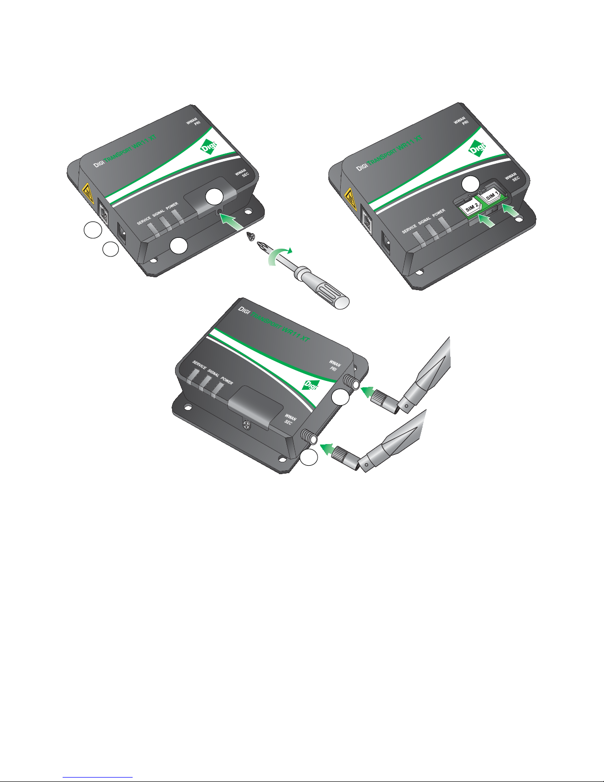
TransPort WR11 hardware
4. SIM door: Encloses the SIM sockets. The SIM door must be removed to install the SIM cards
For installation details, refer to the Quick Start Guide that came with your device.
Note To remove the SIM door, hold the device on a flat surface and using a screwdriver, firmly
pull the cover straight up.
5. Cellular antenna connector: This SMA female connector connects the device’s primary
cellular antenna.
6. SIM Sockets: SIM 1 and SIM 2 are for use with the Subscriber Identification Module(s) (SIMs).
Digi TransPort User Guide 22
Page 23

TransPort WR11 LTE-MIMO hardware features
1
2
5
6
7
3
4
WWAN
PRI
WWAN
SEC
TransPort WR11 hardware
WWAN
PRI
WWAN
SEC
Digi TransPort User Guide 23
Page 24

TransPort WR11 hardware
2
1. LAN port: This Ethernet port connects the device to a 10/100 base-T Local Area Network
(LAN). The port is capable of auto-sensing for speed and wiring, so it can accept both straightthrough or cross-over cable connections.
2. Power cord input: This locking power connector connects the device to a power source. The
connector should be inserted and rotated to lock in place.
3. LEDs:
• SERVICE LED: Indicates the presence and level of cellular service running on the device.
Off: No cellular service
1 Blink: GPRS mode
2 Blinks: EDGE mode
3 Blinks: UMTS mode
4 Blinks: HSDPA mode
5 Blinks: HSUPA mode
6 Blinks: LTE mode
• SIGNAL LED: Indicates strength of cellular signal.
Off: Poor or No signal. Place the device in a location where it gets a better signal.
Amber: Fair
Green: Good
• POWER LED:
Off: No power
Green: TransPort device is powered
4. SIM door: Encloses the SIM sockets. The SIM door must be opened to install the SIM cards. For
installation details, refer to the Quick Start Guide that came with your device.
Note To open the SIM door, slide the SIM door out using your finger.
5. SIM sockets: SIM 1 and SIM 2 are for use with the Subscriber Identification Module(s) (SIMs).
6. Primary LTE antenna connector: This SMA female connector connects the device’s primary
cellular antenna.
7. Secondary LTE antenna connector: This SMA female connector connects the device’s
secondary cellular antenna.
Digi TransPort User Guide 24
Page 25
TransPort WR11 XT
1
2
6
7
4
5
3
TransPort WR11 hardware
1. LAN port: This Ethernet port connects the device to a 10/100 base-T Local Area Network
Digi TransPort User Guide 25
2. Power cord input: This locking power connector connects the device to a power source. The
(LAN). The port is capable of auto-sensing for speed and wiring, so it can accept both straightthrough or cross-over cable connections.
connector should be inserted and rotated to lock in place.
Page 26

TransPort WR11 hardware
3. LEDs:
• SERVICE LED: Indicates the presence and level of cellular service running on the device.
Off: No cellular service
1 Blink: GPRS mode
2 Blinks: EDGE mode
3 Blinks: UMTS mode
4 Blinks: HSDPA mode
5 Blinks: HSUPA mode
6 Blinks: LTE mode
• SIGNAL LED: Indicates strength of cellular signal.
Off: Poor or No signal. Place the device in a location where it gets a better signal.
Amber: Fair
Green: Good
•POWER LED:
Off: No power
Green: TransPort device is powered
4. SIM door: Encloses the SIM sockets. The SIM door must be opened to install the SIM cards. For
installation details, refer to the Quick Start Guide that came with your device.
5. SIM sockets: SIM 1 and SIM 2 are for use with the Subscriber Identification Module(s) (SIMs).
Insert SIM cards with the notch facing the bottom-right corner of the device. If you are using
one SIM card only, insert it in the SIM 1 slot.
6. Primary cellular antenna connector: This SMA female connector connects the device’s
primary cellular antenna.
7. Secondary cellular antenna connector: This SMA female connector connects the device’s
secondary cellular antenna.
Digi TransPort User Guide 26
Page 27

TransPort WR11 hardware specifications
TransPort WR11 hardware
Category
General features Dimensions (L x W x H) 3.9” x 5.2” x 1.3”
Cellular EDGE 850, 900, 1800, 1900 MHz
Power requirements Power input voltage 5V DC ± 5%
Specification
Weight 0.85 lbs.
GSM UMTS / HSPA 800/850, 900, 1700 (AWS),
CDMA 1xRTT 800, 1900 MHz
EVDO 800, 1900 MHz
LTE-AT&T 700 (B17) / 850 (B5) / AWS1700 (B4) / 1900
LTE-Verizon 700 (B13) / AWS1700 (B4)
LTE-Worldwide 800 (B20) / 1800 (B3) / 2600 (B7)
Value
(10 cm x 13.1 cm x 3.2 cm)
1900, 2100 MHz
(B2)
Power 3.5W typical, 15W maximum
Power connector Locking barrel
Environmental Operating temperature 0°C to 40°C required
TransPort WR11 XT only:
-30° to +70°C
See also Restricted Access Location notice
for TransPort WR11 XT on page 89
Relative humidity 5% to 90% (non-condensing)
Storage temperature -40° C to +80° C
TransPort WR11 XT only:
-40°C to+85°C
RoHS compliance Yes
Digi TransPort User Guide 27
Page 28

TransPort WR11 hardware
Category
Specification
Approvals Emissions/Immunity
Safety
Value
EN 55022: 2010 Class B
FCC 15.109(g):2014 Class B
FCC 15.109:2014 Class B
ICES-003:2012 Class B
EN 55022: 2010 Class B
FCC 15.107:2014 Class B
ICES-003:2012 Class B
EN 61000-3-2:2006 (Amended by
A1:2009 and A2:2009) Class B
EN 61000-3-3:2008 Class B
EN 301 489-07 V1.3.1:2005 Class B
EN 550024:2010
EN 301 489-07 V1.3.1:2005
EN 60950-1: :2006 + A1:2010 +
A11:2009 + A12:2011
IEC 60950-1:2005+ A1:2009
UL 60950-1 2nd Ed. Revised 2011-12-
19
CSA C22.2 No. 60950-1 -07 + A1:2011
Mobile certifications-GSM AT&T & PTCRB
Mobile certifications-
Sprint & Verizon
EVDO
Mobile certifications-LTE AT&T; Verizon; PTCRB
Wireless carrier
Certified by most major carriers.
certifications
Digi TransPort User Guide 28
Page 29

TransPort WR21 hardware
POWER SERVICE WWAN
SIGNAL
1
2
3
4
5
6
7
TransPort WR21 front panel features
1. SIM/R-UIM sockets (SIM card models only): SIM 1 and SIM 2 are for use with the Subscriber
Identification Module(s) (SIMs) or Removable User Identification Module(s) (R-UIMs).
2. POWER LED:
• Off: No power
• Green: TransPort device is powered
TransPort WR21 hardware
3. SERVICE LED:
• Off: No WWAN network connection
• Green: WWAN network connection
• Flashing: WWAN traffic being transmitted or received
4. WWAN (Wireless Network) LED: Indicates the presence and level of cellular service running on the
device.
• Off: No cellular service
• 1 Blink: GPRS mode
• 2 Blinks: EDGE mode
• 3 Blinks: UMTS mode
• 4 Blinks: HSDPA mode
• 5 Blinks: HSUPA mode
• 6 Blinks: LTE mode
5. SIGNAL LED: Indicate strength of cellular signal.
• 3 LEDs: Excellent
• 2 LEDs: Good
• 1 LED: Fair
• 0 LEDs: Poor or No signal
6. Reset button: Returns the router to its factory default settings.
7. USB host connector: Connects compatible USB 2.0 client devices such as memory sticks, and
serial adapters. The total current available to power USB devices is 0.5A.
Digi TransPort User Guide 29
Page 30

TransPort WR21 hardware
Reset the TransPort WR21
1. Turn the router on and wait 15 seconds for the router to complete its initialization process.
2. Press and hold the reset button gently for 5 seconds. After this time, the router will
automatically re-boot and display a pattern of alternating LEDs flashing followed by the
normal boot sequence.
CAUTION! Do not remove power from the router during this operation, as corruption of the
flash memory may occur.
Digi TransPort User Guide 30
Page 31

TransPort WR21 rear panel features
WWAN
SECONDARY
SERIAL 0
9-30VDC
2A MAX
1
2 3
4
6
WWAN
PRIMARY
5
LAN 1LAN 0
WWAN
SECONDARY
SERIAL 0
WWAN
PRIMARY
LAN 1LAN 0
9-30VDC
2A MAX
7
TransPort WR21 hardware
1. Secondary cellular (WWAN) antenna connector: This SMA female connector connects the
router’s secondary cellular antenna. It is highly recommended to use the secondary antenna
for diversity. In most circumstances, dual antennas will provide improved signal strength thus
better performance.
2. LAN 0 port: This RJ45 port connects the router to a 10/100 base-TLAN. The port is autosensing for speed and wiring (straight-through or cross-over).
3. LAN 1 port (optional): This RJ45 port connects the router to a 10/100 base-TLAN. The port is
auto- sensing for speed and wiring (straight-through or cross-over).
4. Serial 0 port: This DB9 port provides an asynchronous RS232 (RS485 optional) serial port with
optional RS422/485 support which may be which may be used to connect the router to a
compatible serial device. This is a DCE serial port and allows CLI access to the device by
default; the baud rate is 115200. For a pinout, see TransPort WR21 serial pinout on page 32.
5. Power cord input: This socket connects the router to a power source using either the
supplied Power supply or DC power cord. The barrel plug connector can be secured by
rotating it by 90 degrees once installed into the Digi TransPort router.
6. Primary cellular (WWAN) antenna connector: This SMA female connector connects the
router’s primary cellular antenna.
7. Power cord input (terminal block variant): This socket connects the router to an alternative
power source.
Digi TransPort User Guide 31
Page 32

TransPort WR21 serial pinout
WWAN
SECONDARY
SERIAL 0
9-30VDC
2A MAX
WWAN
PRIMARY
LAN 1LAN 0
SERIAL 0
Pin 1
Pin 9
TransPort WR21 hardware
RS-232 pinout
Pin # Direction RS232 DCE Description
1 Out DCD Data Carrier Detect
2 Out RXD Receive Data
3In TXD Transmit Data
4In DTR Data Terminal Ready
5N/A GND Ground
6 Out DSR Data Set Ready
7In RTS Ready To Send
8Out CTS Clear To Send
9 Out RI Ring Indicate
Digi TransPort User Guide 32
Page 33

TransPort WR21 hardware
RS422/ RS485 pinout
Pin # Direction RS422/ RS485 Description
1Out CTS- Clear To Send -
2 Out RD+ Receive Data +
3 In TD+ Transmit Data +
4 In RTS_B RTS- Ready To Send -
5N/A GND Ground
6 Out RD- Receive Data -
7In RTS+ Ready To Send +
8Out CTS+ Clear To Send +
9In TD- Transmit -
Notes
• For true RS485 mode (2-wire half-duplex mode), the TD+ and RD+ pair and TD- and RD- pair
should be connected together.
• The CTS and RTS signals for optional and not normally needed for RS485.
Digi TransPort User Guide 33
Page 34

TransPort WR21 hardware
TransPort WR21 hardware specifications
Category Specification Value
General features Dimensions (L x W x H) 3.9” x 5.2” x 1.3” (10 cm x 13.1 cm x 3.2
cm)
Weight 0.85 lbs.
Other Standard dual SIM (SIM protection cover
option)
RF features
GSM models GPRS
EDGE
HSDPA/HSUPA/UMTS 850/900/1900/2100 MHz with Rx
CDMA models CDMA/EV-DO Rev A
Power requirements Power input 9-30 VDC
Power supply
•GPRS Class 10
• Quad band 850/900/1800/1900 MHz
• GPRS Class 10/EDGE Class 10
• Quad band 850/900/1800/1900 MHz
Diversity
• Dual band 800/1900 MHz with Rx
Diversity
• Optional multi-mode GSM/ EV-DO
Gobi support
• 450 MHz, 3.1 Mbps down / 1.8 Mbps
up
•R-UIM support
• 100-240 VAC 50/60 Hz with barrel
connector
• Optional barrel connector with bare
wire leads
Environmental Operating temperature -20° C to +55° C; -35° C to +75° C with
Digi TransPort User Guide 34
Power consumption 6W @ 12 VDC
reduced cellular performance
Relative humidity 20% to 95% (non-condensing)
Ethernet isolation 1.5 kV
Serial port protection (ESD) 1.5 kV
Page 35

Category Specification Value
TransPort WR21 hardware
Approvals Emissions/Immunity
Safety
Mobile Certifications-GSM/
UMTS
Mobile Certifications-CDMA/
EV-DO
Wireless Carrier
Certifications
Safety
•CE
• FCC Part 15 Class B
• AS/NZS CISPR 22
• EN55022 Class B
• EN55024
• UL 60950
• CSA 22.2 No. 60950
• EN60950
•R&TTE
• EN 301 511
•CDG TIA/EIA-690
•CDG TIA/EIA-98-E
Certified by most major carriers. See
www.digi.com for current listing.
• UL 60950
• CSA 22.2 No. 60950
• EN60950
Emissions / Immunity
• CE, FCC Part 15 Class B
• AS/NZS CISPR 22
• EN55022 Class A
Digi TransPort User Guide 35
Page 36

TransPort WR31 hardware
0
WWAN PRI
9-30VDC
2A MAX
1
0
WWAN PRI
9-30VDC
2A MAX
2
0
WWAN PRI
9-30VDC
2A MAX
1
3
5
6
7
WW
AN PRI
9-30VDC
2
A MAX
9
8
12
11
10
4
TransPort WR31 hardware features
TransPort WR31 hardware
Digi TransPort User Guide 36
Page 37

TransPort WR31 hardware
1. SIM card slot cover: On the underside of the router. Remove and replace with a Phillips-head
screwdriver.
2. SIM 1 and SIM 2 card slots: On the underside of the router. SIM 1 and SIM 2 are for use with
the Subscriber Identification Module(s) (SIMs) or Removable User Identification Module(s) (RUIMs). when inserting the SIM card(s) into SIM sockets, SIM 1 is to the middle of the router,
and SIM 2 is toward the outside of the router. In both cases, the end of the SIM card with the
chamfered corner should be inserted first.
3. LAN 0 port: This RJ45 port connects the router to a 10/100 base-TLAN. The port is autosensing for speed and wiring (straight-through or cross-over).
4. LAN 1 port: This RJ45 port connects the router to a 10/100 base-TLAN. The port is autosensing for speed and wiring (straight-through or cross-over).
5. USB host connector: Connects compatible USB 2.0 client devices such as memory sticks, and
serial adapters. The total current available to power USB devices is 0.5A.
WARNING! The USB port is for use in a normal location only, not a hazardous location.
6. Serial connector: This DB9 port provides an asynchronous RS232 (RS485 optional) serial port
with optional RS422/485 support which may be which may be used to connect the router to a
compatible serial device. This is a DCE serial port and allows CLI access to the device by
default; the default serial baud rate is 115200. For a pinout, see TransPort WR31 serial pinou t
on page 39.
7. Power connector: A pluggable connector that connects the router to a power source using
either the separately available power supply: Digi part number 76000736, or a DIN rail power
supply.
8. WWAN primary connector: This SMA male connector connects the router’s primary cellular
antenna.
9. WWAN secondary connector: This SMA male connector connects the router’s secondary
cellular antenna. For multiple-input and multiple-output (MIMO), both cellular antennas are
needed for downloading data.
10.LEDs: Indicate startup states and status for various signals and services:
• POWER LED:
Off: No power
Green: TransPort device is powered
• SERVICE LED:
Off: No WWAN network connection
Green: WWAN network connection
Flashing: WWAN traffic being transmitted or received
• WWAN LED: Indicates the presence and level of cellular service running on the device.
Off: No cellular service
1 Blink: GPRS mode
2 Blinks: EDGE mode
3 Blinks: UMTS mode
Digi TransPort User Guide 37
Page 38

4 Blinks: HSDPA mode
5 Blinks: HSUPA mode
6 Blinks: LTE mode
• SIGNAL LEDs: Indicate strength of cellular signal.
3 LEDs: Excellent
2 LEDs: Good
1 LED: Fair
0 LEDs: Poor or No signal
• SYSTEM LED: Reserved for user-defined functions.
11.Earth ground
TransPort WR31 hardware
12.Digital/analog I/O connector:
Aninput/outputconnectorwithtwodigitalinput/output
connections,andasingleanaloginputconnection.Formoreinformationandwiringdiagrams,see
TransPortWR31digitalandanaloginputsandoutputs
on page 41.
TransPort WR31 mounting options
The TransPort WR31 can be mounted on a DIN rail, directly to a wall, or in a NEMA enclosure. For
wall-mounting or NEMA enclosure installation, purchase the TransPort WR31 Wall Mount Bracket
(Digi part number 76000963) and NEMA enclosure equipment, such as the NEMA enclosure,
mounting plate, special cabling, and cable glands.
Hazardous Location installation
ForHazardousLocationinstallation,see the TransPort WR31 Hazardous Locations User Guide (Digi
part number 90001490) on www.digi.com.
Digi TransPort User Guide 38
Page 39

TransPort WR31 serial pinout
WWAN PRI
9-30VDC
2A MAX
Pin 1
Pin 9
TransPort WR31 hardware
Digi TransPort User Guide 39
Page 40

RS-232 pinout
Pin # Direction RS232 DCE Description
1 Out DCD Data Carrier Detect
2 Out RXD Receive Data
3In TXD Transmit Data
4In DTR Data Terminal Ready
5N/A GND Ground
6 Out DSR Data Set Ready
7In RTS Ready To Send
8Out CTS Clear To Send
9 Out RI Ring Indicate
RS422/ RS485 pinout
Pin # Direction RS422/ RS485 Description
1Out CTS- Clear To Send -
2 Out RD+ Receive Data +
3 In TD+ Transmit Data +
4 In RTS_B RTS- Ready To Send -
5N/A GND Ground
6 Out RD- Receive Data -
7In RTS+ Ready To Send +
8Out CTS+ Clear To Send +
9In TD- Transmit -
TransPort WR31 hardware
Notes
• For true RS485 mode (2-wire half-duplex mode), the TD+ and RD+ pair and TD- and RD- pair
should be connected together.
• The CTS and RTS signals for optional and not normally needed for RS485.
Digi TransPort User Guide 40
Page 41

TransPort WR31 hardware
TransPort WR31 digital and analog inputs and outputs
TheTransPortWR31hasaninput/outputconnectorwithtwodigitalinput/outputconnections,anda
singleanaloginputconnection.
I/O connector pin assignments
The following figure and table shows the I/O connector, pin assignments, and the signals for each
pin.
Pin 5
Pin 1
Pin # Symbol Description
5AIN0 Analog Input 0
4AGND Analog Return
3 DIO0 Digital I/O 0
2GND Digital Return
1 DIO1 Digital I/O 1
Digi TransPort User Guide 41
Page 42

TransPort WR31 hardware
WR31_3v3
PullͲupEnableSignal
DigitalOutputEnable
DigitalInput
DIGITALINPUT
DIGITALRETURN
200ͲOhm
AnalogSelectSignal
AnalogInput
ANALOGINPUT
ANALOGRETURN
CurrentLoop
Protector
CurrentLoopSignal
VoltageInputSignal
TransPort WR31 digital input/output: representative circuit
TransPort WR31 analog input: representative circuit
Digi TransPort User Guide 42
Page 43

Example digital and analog I/O wiring
DIGITALINPUT
DIGITALRETURN
DigitalInput
WR31_3v3
PullͲupON
ExternalContact
(DoorContact,
etc.)
DIGITALINPUT
DIGITALRETURN
DigitalInput
ExternalContact
(DoorContact,
etc.)
DigitalOutputEnable
DIGITALRETURN
DIGITALINPUT
Digital input with pullup
TransPort WR31 hardware
Digital input without pullup
NotethatinputisHIGHwhencontactisCLOSED.
Digital output
The wiring diagram assumes a current-limiting resistor provided by installation or connected
device is in use.
Digi TransPort User Guide 43
Page 44

Analog input, 4-20mA input mode
200ͲOhm
AnalogInput
CurrentLoop
Protector
ANALOGINPUT
ANALOGRETURN
ANALOG4Ͳ20mA
Sensor
AnalogSelectSignal
(CurrentMode)
AnalogInput
ANALOGINPUT
ANALOGRETURN
0–10Vinput
AnalogSelectSignal
(VoltageMode)
DC
Analog input, 0-10V input mode
TransPort WR31 hardware
Digital and analog I/O specifications
Digital I/O specifications
Specification MIN NOM MAX UNITS
Rated Input Voltage -0.2 30 V
Rated Input Current -1.0 200 mA
Pull-Up Resistance 10 k Ohms
Digital input specifications
• This input is a non-inverting Schmitt-trigger input.
Digi TransPort User Guide 44
• The default state at power-up with no voltage applied is LOW.
Page 45

Specification MIN NOM MAX UNITS
+ Threshold .. 1.6 .. V
- Threshold .. 1.0 .. V
Input impedance 1 M Ohms
Digital output
• This output is an open-collector, sinking driver output.
• The default state at power-up is OFF.
Specification MIN NOM MAX UNITS
SinkCurrent .. .. 200 mA
Pull‐upVoltage 3 V
TransPort WR31 hardware
Digi TransPort User Guide 45
Page 46

Analog input specifications
Specification MIN NOM MAX UNITS
Resolution .. .. 12 BITS
Accuracy .. .. 0.2 %
RatedInputVoltage ‐0.2 30 V
RatedInputCurrent 0 40 mA
Voltage input mode (default)
Specification MIN NOM MAX UNITS
Input Voltage -0.2 .. 10.25 V
Input Impedance .. 291 K .. Ohms
Current loop mode
Specification MIN NOM MAX UNITS
TransPort WR31 hardware
Minimum Input Voltage .. 2 .. V
Load Resistance .. 200 .. Ohms
Digi TransPort User Guide 46
Page 47

TransPort WR31 hardware specifications
Category Specification Value
TransPort WR31 hardware
3G/4G LTE
Specifications
LTE-North America(L5)
LTE-North America(L6)
LTE-EMEA/APAC(L1)
HSPA+ -(U9)
Connectors
• Software-Defined Multi-Carrier (Verizon, AT&T, and
Sprint)
• 700/850/1700(AWS)/1900 MHz
• 2G/3G GSM fall back to850/900/1700AWS/1800/
1900/2100 MHz
• 2G/3G CDMA fall back to 800/1900 MHz
• Transfer Rate (max): 50 Mbps Up, 100 Mbps Down
• 700/850/1700 (AWS)/1900 MHz
• 2G/3G fall back to 850/1900 MHz
• Transfer Rate (max): 50 Mbps Up, 100 Mbps Down
• 800/850/900/1800/1900/2100/2600 MHz
• 3G fall back to 850/900/1900/2100 MHz
• 2G fall back to 850/900/1800/1900 MHz
• Transfer Rate (max): 50 Mbps Up, 100 Mbps Down
• 850/900/1700 (AWS)/1900/2100 MHz
• Transfer Rate (max): 5.76 Mbps Up, 21 Mbps Down
• 1 x 50
• 2x connectors for LTE models
SMA (Center pin: female)
Software and
Management
SIM Slots 2
SIM Security Screw-down SIM cover
Remote Management
Local Management
Management/
Troubleshoo ting
Memory
tools
•Digi Remote Manager
• SNMPv1/v2c/v3
•Web UI (HTTP/HTTPS)
• CLI (Telnet, SSH, SMS)
• FTP, SFTP, SCP
• Protocol analyzer with PCAP for Wireshark
• Event logging with Syslog and SMTP
•NTP/SNTP
• 20 MB RAM
• 10 MB file space
Digi TransPort User Guide 47
Page 48

Category Specification Value
Ethernet Ports (2) RJ-45ports
Physical Layer 10/100Base-T
Data Rate 10/100 Mbps (auto-sensing)
Mode Full or half duplex (auto-sensing)
Interface Auto MDI/MDIX
Serial Ports (1) RS-232/422/485
DTE/DCE DCE
Signal Support TXD, RXD, RTS, CTS, DTR, DCD, DSR, RI
TransPort WR31 hardware
Flow Control
• Software (XON/XOFF)
• Hardware supported
®
Digital and analog I/O
COM Port Redirector
Digi RealPort
Connector (5) pin screw-down terminal block
(see also TransPort
WR31 digital and
analog inputs and
outputs on page 41)
Digital 0-30VDC. (2) I/O, software-selectable
Analog
• (1) analog input
• 4-20mA or 0-10V
• Software Selectable
• 12 bit resolution
USB Ports (1) USB Type A
Standard USB2.0
Physical Dimensions (L x W x H) 5 in x 3.5 in x 2 in (12.7 cm x 8.9 cm x 5.1cm);
Weight 1.1 lb. (.5kg)
Status LEDs
•Power
•Service
•WWAN
Enclosure Aluminum
Mounting DIN rail, wall, shelf mount, or NEMA enclosure mount
Power requirements Power input 9-30VDC
Power connector Screw down removable terminal block
Power consumption Typical 4 W (Max 6 W)
Digi TransPort User Guide 48
• Signal strength (3x)
• System (user-programmable LED)
Page 49

Category Specification Value
Environmental Hazardous (Class 1 Div 2) Yes
Operating Temperature -30° C to +70° C (-22° F to +158°F)
Reduced cellular performance above 60°C
Storage Temperature -40° C to +85° C (-40° F to +185°F)
Ethernet Isolation 1.5 kV RMS
TransPort WR31 hardware
Serial Port Protection
15kV
(ESD)
Relative Humidity 5% to 95% (non-condensing)
Approvals Safety Hazardous Locations:
• ANSI/ISA-12.12.01-2015
• CAN/CSA C22.2 NO.213-15
• EN 60079-0:2012+A11:2013
• EN 60079-15:2010
• See the TransPort WR31 Hazardous Locations User
Guide, Digi part number 90001490.
Ordinary Locations:
• UL 60950-1, 2nd Edition, 2014-10-14
Emissions/Immunity
•CE
•FCC Part15 Class B
• AS/NZS CISPR22
• EN55024
• EN55022 Class B
GSM/UMTS PTCRB
Cellular Carriers Certified by most major carriers. See www.digi.com
Warranty Product Warranty 5 years
Digi TransPort User Guide 49
for a full list.
Page 50

TransPort WR41 hardware
1
2
3
4
5
6
7
8
9 10
11
12
TransPort WR41 front panel features
1. USB host connector: The USB host connector may be used to connect compatible USB 2.0
client devices such as memory sticks, and serial adapters. The total current available to power
USB devices is 0.5A.
2. POWER LED:
• Off: No power
TransPort WR41 hardware
• Green: TransPort device is powered
3. Secondary Wi-Fi antenna connector (Wi-Fi models only): This SMA connector is used to
connect the router’s secondary Wi-Fi antenna (if fitted).
4. LAN LED: Illuminates steadily when there is a network connection to the LAN port and flashes when
data is transmitted or received.
5. WN LED:
• Wi-Fi models: Illuminates steady if Wi-Fi activity is present.
• Non-Wi-Fi models: Flashes to show which network mode the router is operating in:
Off: No service
1 blink: GPRS mode
2 blinks: EDGE mode
3 blinks: UMTS mode
4 blinks: HSDPA mode
5 blinks: HSUPA mode
6 blinks: LTE mode
6. LINK LED: Illuminates steadily when a wireless WAN data connection has been established.
7. SIM LED: Illuminates steadily when a valid SIM card is installed.
8. ACT LED: Flashes to indicate that data is being transferred over the wireless WAN network.
Digi TransPort User Guide 50
Page 51

TransPort WR41 hardware
9. SIGNAL LEDs: Indicate strength of cellular signal.
• 3 LEDs: Excellent
• 2 LEDs: Good
• 1 LED: Fair
• 0 LEDs: Poor or No signal
10.SERIAL LED: Illuminates steady if a terminal is connected to the SERIAL port and the DTR
signal is on. Flashes when data is transmitted or received.
11.Primary Wi-Fi antenna connector (Wi-Fi models only): This SMA connector is used to
connect the router’s primary Wi-Fi antenna.
12.SIM / R-UIM Sockets (SIM card models only): SIM 1 and SIM 2 are for use with the Subscriber
Identification Module(s) (SIMs) or Removable User Identification Module(s) (R-UIMs).
Digi TransPort User Guide 51
Page 52

TransPort WR41 rear panel features
WWAN
SECONDARY
WWAN
PRIMARY
LAN
GND
SERIAL 0
1
2
3
4
5
6
7
9-48VDC
2A MAX
WWAN
1
WWAN
2
9-48VDC
3
SERIAL 0
TransPort WR41 hardware
6
4
5
GND
PRIMARY
7
LAN
Digi TransPort User Guide 52
Page 53

TransPort WR41 under-unit features
Front of unit
Rear of unit
TransPort WR41 hardware
Reset button
The reset button allows the user to return the router to its factory default settings. It is recessed
[to avoid accidental reset], and can be accessed via a small 2.5mm hole located on the underside
of the router.
Reset the router
1. Turn the router on and wait 15 seconds for the router to complete its initialization process.
2. Press and hold the reset button gently for 5 seconds. After this time, the router will
automatically re-boot and display a pattern of alternating LEDs flashing followed by the
normal boot sequence.
CAUTION! Do not remove power from the router during this operation, as corruption of the
flash memory may occur.
Digi TransPort User Guide 53
Page 54

TransPort WR41 additional hardware features
ANT.
(AUX.)
ANT.
(MAIN)
LAN
GND
ASY 0
9-48VDC
2A MAX
SERIAL 1
ISDN
SERIAL 1
SERIAL 3
SERIAL 2
Option 1: ASY Serial Port
Option 3: SYN/ASYN Serial Port
Option 5: ISDN
Option 10: ISDN-U/PSTN
PSTN
Option 9: PSTN
ISDN
Modem
Option 11: DialServ
To Modem
Option 2: ASY Serial Port (3x)
GPS
Option 4: GPS
Option 6: Telemetry 1 I/O Inter face
AB AB
+
_
DC IN
RLY
IN OUT 1 OUT 2
OUT 3
+_+_+
_
OUT 4
Option 7: Telemetry 2 I/O Inter face
ABAB
AB
A
B
D1 D2 D3 D4
AN1
AN2
AN3 AN4 D12C
D34C
Option 8: Fleet I/O Interface
Pwr Data
GPS
SERIAL 1
TransPort WR41 hardware
Digi TransPort User Guide 54
Page 55

TransPort WR41 hardware
1. ASY Serial Port: Provides an additional asynchronous RS232 serial port using a DB25
connector.
2. ASY Serial Port (3x): Provides three additional asynchronous RS232 serial ports using RJ45
connectors.
3. SYN/ASYN Serial Port: Provides an X.21/RS422/RS232 synchronous / asynchronous serial
port using a DB25 connector.
4. GPS: Provides GPS capabilities using an SMA male connector.
5. ISDN: Provides an ISDN Basic Rate Interface (BRI) via an RJ45 port. This can be configured
either as a TE (terminal endpoint) or as NT-1 (network termination). The option also includes
an additional asynchronous serial port via a second RJ45 port.
6. Telemetry 1 I/O Interface: Provides 4 opto-isolated digital input ports and 1 opto-isolated
digital output port. It also provides a relay I/O port, a voltage monitoring port, and internal
temperature monitoring.
7. Tel emetry 2 I/O Interface: Provides 4 isolated analog I/O ports and 4 non-isolated digital I/O
ports.
8. Fleet I/O Interface: Provides CAN and J1708 interface, GPS, 4 non-isolated digital I/O ports,
ignition sense port, and a 3 axis accelerometer.
9. PSTN: Provides a PSTN interface via an RJ45 connector that can be used to dial out and receive
calls.
10.ISDN-U/PSTN: Provides an ISDN-U interface suitable for the USA plus PSTN interface. It can be
configured for Bell-103 modulation in leased line mode as well as a normal PSTN interface.
11.DialServ: This RJ11/FXS connection converts a PSTN analog modem to a RS-232 serial signal.
For more information on the Telemetry 1, Telemetry 2, and the Fleet I/O Interfaces please see the
product specific user’s guides, available on www.digi.com on the TransPort WR41 product
Resources page.
Digi TransPort User Guide 55
Page 56

TransPort WR41 serial pinout
WWAN
SECONDARY
WWAN
PRIMARY
LAN
GND
SERIAL 0
9-48VDC
2A MAX
SERIAL 0
Pin 8Pin 1
DB25 connector available
on some daughter cards
TransPort WR41 hardware
RS-232 port pinouts
Description RS232 signal Direction1DB 25 Pin#
Transmit Data TxD in 2 6
Receive Data RxD out 3 3
Ready To Send RTS in 4 1
Clear To Send CTS out 5 8
Data Set Ready DSR out 6 n/a
Ground GND n/a 7 5
Data Carrier Detect DCD out 8 7
Transmitter Clock TxC out 15 n/a
Receiver Clock RxC out 17 n/a
Data Terminal Ready DTR in 20 2
RJ45 Pin#
Ring Indicate RI out 22 n/a
External Transmitter Clock ETC in 24 n/a
1 With respect to Digi routers
Digi TransPort User Guide 56
Page 57

TransPort WR41 hardware
Asynchronous port (ASY 0) pinout
ANT. ANT.
9-48VDC
Pin 1
ASY 0
Pin 8
GND
ASY 0
Pin # Direction RS232 DCE Description
1In RTX Ready To Send
2In DTR Data Terminal Ready
3 Out RxD Receive Data
4- - -
5N/A GND Ground
6In TxD Transmit Data
7 Out DCD Data Carrier Detect
8Out CTS Clear To Send
LAN
Digi TransPort User Guide 57
Page 58

TransPort WR41 hardware
TransPort WR41 hardware specifications
Category Specification Value
General features Dimensions (L x W x H) 4.7” x 6.8” x 1.3” (12 cm x 17.3 cm x 3.2 cm)
Weight 1.08 lb (0.49Kg)
Other Standard dual SIM (SIM protection cover option)
RF features: GSM Models GPRS
EDGE
HSDPA/HSUPA/UMTS 850/900/1900/2100 MHz with Rx Diversity
RF features: CDMA
models
Power requirements Power Input 8-48 VDC
Environmental Operating Temperature
CDMA/EV-DO Rev A
Power Supply
Power Consumption 6W @ 12 VDC to WR41
•GPRS Class 10
• Quad band 850/900/1800/1900 MHz
• GPRS Class 10/EDGE Class 10
• Quad band 850/900/1800/1900 MHz
• Dual band 800/1900 MHz with Rx Diversity
• Optional multi-mode GSM/ EV-DO Gobi
support
• 450 MHz
• 3.1 Mbps down / 1.8 Mbps up
•R-UIM support
• 100-240 VAC 50/60 Hz with barrel connector
• Optional barrel connector with bare wire leads
• -20° C to +55° C
• -25° C to +70° C with reduced cellular
performance
Relative Humidity 20% to 95% (non-condensing)
Ethernet Isolation 1.5 kV
Serial Port Protection (ESD) 1.5 kV
Digi TransPort User Guide 58
Wi-Fi models:
• -5° C to +55° C
• -10° C to +70° C with reduced performance
Page 59

Category Specification Value
TransPort WR41 hardware
Approvals Emissions/Immunity
Safety
Mobile Certifications-GSM/
UMTS
Mobile CertificationsCDMA/ EV-DO
Wireless Carrier
Certifications
• EN55022 Class B
•CE
• FCC Part 15 Class B
• AS/NZS CISPR 22
• EN55024
• UL 60950
• CSA 22.2 No. 60950
• EN60950
•PTCRB
•NAPRD.03
•GCF-CC
•R&TTE
• EN 301 511
•CDG TIA/EIA-690
•CDG TIA/EIA-98-E
Certified by most major carriers. See
www.digi.com for current listing.
Vehicle Related
Certifications
• 2004/104/EC
• 2005/49/EC
• 2005/83/EC
• 2006/28/EC
• 72/245/EEC
• ISO7637-2 Class C
Digi TransPort User Guide 59
Page 60

TransPort WR44 / WR44 R hardware
2
1
2
2
1
2
TransPort WR44 enclosure features
TransPort WR44
TransPort WR44 / WR44 R hardware
1. Commercial enclosure
2. Mounting feet
TransPort WR44 R
1. Rugged enclosure
2. Mounting tabs
Digi TransPort User Guide 60
Page 61

TransPort WR44 / WR44 R hardware
1
2
3
4
5
6
7
8
9
10
1
2
3
4
5
6
7
8
9
TransPort WR44 front panel features
TransPort WR44 models with cellular interface
TransPort WR44 models without cellular interface
Digi TransPort User Guide 61
Page 62

TransPort WR44 / WR44 R hardware
1. USB host connector: The USB host connector may be used to connect compatible USB 2.0
client devices such as memory sticks, and serial adapters. The total current available to power
USB devices is 0.5A.
2. POWER LED:
• Off: No power
• Green: TransPort device is powered
3. LAN (0, 1, 2, 3) LED: Illuminates steadily when there is a network connection to the LAN port and
flashes when data is transmitted or received.
4. Wi-Fi LED:
• Wi-Fi models: Illuminates steady if Wi-Fi activity is present.
5. SERIAL LED: Illuminates steadily if a terminal is connected to the SERIAL port and the DTR
signal is on. Flashes when data is transmitted or received.
6. LINK LED: Illuminates steadily when a wireless data connection has been established.
7. SIM LED:
• Cellular models: Illuminates steadily when a valid SIM card is installed.
• Models without cellular interface: Not operational.
8. ACT LED: Flashes to indicate that data is being transferred over the wireless network.
9. SIGNAL LED:
• Cellular models: Indicate strength of cellular signal.
3 LEDs: Excellent
2 LEDs: Good
1 LED: Fair
0 LEDs: Poor or No signal
• Models without cellular interface: Not operational.
10.SIM / R-UIM Sockets:
• Cellular SIM card models only): Illuminates steadily when a valid SIM card is installed.
• Models without cellular interface: Not operational.
Digi TransPort User Guide 62
Page 63

TransPort WR44 / WR44 R hardware
WWAN PRIMARY WIFI SECONDARY
11-58VDC
1.3A MAX
MAIN
AUX.
WIFI PRIMARYWWAN SECONDARY
LAN3
LAN2 LAN1
LAN0
SERIAL 0
1
7
2 3 4
8
5 6
9
TransPort WR44 rear panel features
1. Primary cellular (WWAN) antenna connector: This SMA female connector is used to
connect the router’s primary cellular antenna.
2. Secondary Wi-Fi (WLAN) Antenna connector (Wi-Fi models only): This SMA male connector
is used to connect the router’s secondary Wi-Fi antenna.
3. Secondary cellular (WWAN) antenna connector (WR44-U and WR44-C models): This SMA
female connector is used to connect the router’s secondary cellular antenna. It is highly
recommended to use the secondary antenna for diversity. In most circumstances, dual
antennas will provide improved signal strength thus better performance.
4. Primary Wi-Fi (WLAN) antenna connector (Wi-Fi models only): This SMA male connector is
used to connect the router’s primary Wi-Fi antenna.
5. Power cord input: This socket is used to connect the router to a power source.
Note The power supply has a twist-lock connector which can be secured by rotating it 90
degrees once installed into the TransPort router.
6. 11-58VDC (Aux): This socket can be used to connect the router to an alternative 11-58VDC
power supply (not supplied) using a fused power cable which can be purchased separately.
This cable also contains two programmable IO signal lines, one is an input signal, and the
other is an input/output signal.
7. SERIAL 0 port: This DB9 port provides an asynchronous RS232 serial port which may be used
to connect the router to a compatible serial device. This is a DCE serial port and allows CLI
access to the device by default; the baud rate is 115200.
8. Hardware expansion port: Various hardware upgrades are available for this router and are
populated via this expansion port. See the TransPort WR44 additional hardware features on
page 66 section for further information.
9. LAN ports: These RJ45 ports are used to connect the router to a 10/100 base-T LAN. These
ports are auto- sensing for speed and wiring (straight-through or cross-over).
Digi TransPort User Guide 63
Page 64

TransPort WR44 under unit features
[Front of Unit]
1
2
3
1
[Rear of Unit]
TransPort WR44
TransPort WR44 / WR44 R hardware
Digi TransPort User Guide 64
Page 65

TransPort WR44 R
[Front of Unit]
[Rear of Unit]
3
TransPort WR44 / WR44 R hardware
1. Mounting holes.
2. SIM slot cover plate mounting hole.
3. Reset button: The reset button allows the user to return the router to its factory default
settings. It is recessed [to avoid accidental reset], and can be accessed via a small 2.5mm hole
located on the underside of the router.
Reset the TransPort WR44/WR44 R
1. Turn the router on and wait 15 seconds for the router to complete its initialization process.
2. Press and hold the reset button gently for 5 seconds. After this time, the router will
automatically re-boot and display a pattern of alternating LEDs flashing followed by the
normal boot sequence.
CAUTION! Do not remove power from the router during this operation, as corruption of the
flash memory may occur.
Digi TransPort User Guide 65
Page 66

TransPort WR44 additional hardware features
WWAN PRIMARY
WIFI SECONDARY
11-58VDC
1.3A MAX
MAIN
AUX.
WIFI PRIMARYWWAN SECONDARY
LAN3 LAN2 LAN1 LAN0
SERIAL 0
Option 1: ASY Serial Port (3x)
Option 3: GPS
Option 5: Telemetry 1 I/O Interface
Option 10: DialServ
Option 9: ISDN-U/PSTN
SERIAL 1
SERIAL 3
SERIAL 2
Option 2: SYN/ASYN Serial Port
Option 4: ISDN
GPS
Option 6: Telemetry 2 I/O Interface
AB AB
+
_
DC IN
RLY
IN OUT 1 OUT 2
OUT 3
+_+_+
_
OUT 4
Option 7: Fleet I/O Interface
Option 8: PSTN
Pwr Data
GPS
ISDN
Modem
ISDN
ABAB
AB
A
B
D1 D2 D3 D4
AN1
AN2
AN3 AN4 D12C
D34C
PSTN
To Modem
SERIAL 1
TransPort WR44 / WR44 R hardware
Digi TransPort User Guide 66
Page 67

TransPort WR44 / WR44 R hardware
1. ASY serial port (3x): Provides three additional asynchronous RS232 serial ports using RJ45
connectors.
2. SYN/ASYN serial port: Provides an X.21/RS422/RS232 synchronous / asynchronous serial
port using a DB25 connector.
3. GPS antenna connector (GPS models only): Provides GPS capabilities using an SMA male
connector.
4. ISDN: Provides an ISDN Basic Rate Interface (BRI) via an RJ45 port. This can be configured
either as a TE (terminal endpoint) or as NT-1 (network termination). The option also includes
an additional asynchronous serial port via a second RJ45 port.
5. Tel emetry 1 I/O interface: Provides 4 opto-isolated digital input ports and 1 opto-isolated
digital output port. It also provides a relay I/O port, a voltage monitoring port, and internal
temperature monitoring.
6. Tel emetry 2 I/O interface: Provides 4 isolated analog I/O ports and 4 non-isolated digital I/O
ports.
7. Fleet I/O interface: Provides CAN and J1708 interface, GPS, 4 non-isolated digital I/O ports,
ignition sense port, and a 3 axis accelerometer.
8. PSTN: Provides a PSTN interface via an RJ45 connector that can be used to dial out and receive
calls.
9. ISDN-U/PSTN: Provides an ISDN-U interface suitable for the USA plus PSTN interface. It can be
configured for Bell-103 modulation in leased line mode as well as a normal PSTN interface.
10.DialServ: This RJ11/FXS connection converts a PSTN analog modem to a RS-232 serial signal.
For more information on the Telemetry 1, Telemetry 2, and the Fleet I/O Interfaces please see the
product specific user’s guides, available on www.digi.com on the TransPort WR44 product
Resources page.
Digi TransPort User Guide 67
Page 68

TransPort WR44 / WR44 R hardware
TransPort WR44 / WR44 R serial pinout
RS-232 port Pin Outs
Description RS232 signal Direction1DB 25 Pin# DB 9 Pin# RJ45 Pin #
Transmit Data TxD in 2 3 6
Receive Data RxD out 3 2 3
Ready To Send RTS in 4 7 1
Clear To Send CTS out 5 8 8
Data Set Ready DSR out 6 6 n/a
Ground GND n/a 7 5 5
Data Carrier
Detect
Transmitter
Clock
Receiver Clock RxC out 17 n/a n/a
Data Terminal
Ready
Ring Indicate RI out 22 9 n/a
External
Transmitter
Clock
1 With respect to Digi routers
DCD out 8 1 7
TxC out 15 n/a n/a
DTR in 20 4 2
ETC in 24 n/a n/a
Digi TransPort User Guide 68
Page 69

TransPort WR44 / WR44 R hardware
TransPort WR44 / TransPort WR44 R hardware specifications
Category Specification Value
General features Dimensions (L x W x H) 5.7” x 8.3” x 1.6” (145 mm x 210 mm x 40 mm)
Weight 1.98 lb (0.9Kg)
Other Standard dual SIM (SIM protection cover option);
Conformal coating (option)
RF features
GSM models GPRS
EDGE
HSDPA/HSUPA/UMTS 850/900/1900/2100 MHz with Rx Diversity
CDMA models CDMA/EV-DO Rev A
Power requirements Power Input 11-58 VDC
Power Supply
Power Consumption 15W @ 12 VDC to WR44
Environmental Operating Temperature
•GPRS Class 10
• Quad band 850/900/1800/1900 MHz
• GPRS Class 10/EDGE Class 10
• Quad band 850/900/1800/1900 MHz
• Dual band 800/1900 MHz with Rx Diversity
• Optional multi-mode GSM/EV-DO Gobi support
• 450 MHz
• 3.1 Mbps down / 1.8 Mbps up
• R-UIM support
• 100-240 VAC 50/60 Hz with barrel connector
• Optional Molex connector with bare wire leads
• WR44: 0° C to +60° C
• WR44 Extended Temp/WR44R:
-40° C to +75° C;
-20° C to +75° C (Wi-Fi models only)
• Reduced cellular performance may occur above
+60° C
Relative Humidity 20% to 95% (non-condensing)
Ethernet Isolation 1.5 kV
Serial Port Protection (ESD) 1.5 kV
Digi TransPort User Guide 69
Page 70

Category Specification Value
TransPort WR44 / WR44 R hardware
Approvals Emissions/Immunity
Safety
Mobile Certifications-GSM/
UMTS
Mobile Certifications-CDMA/
EV-DO
Wireless Carrier
Certifications
•CE
• FCC Part 15 Class B
• AS/NZS CISPR 22
• EN55024
• EN55022 Class B (WR44 models with VDSL are
Class A)
• UL 60950
• CSA 22.2 No. 60950
• EN60950
•PTCRB
•NAPRD.03
•GCF-CC
•R&TTE
• EN 301 511
•CDG TIA/EIA-690
•CDG TIA/EIA-98-E
Certified by most major carriers. See www.digi.com
for current listing.
Safety
Emissions / Immunity
Vehicle Related
Certifications
• UL 60950
• CSA 22.2 No. 60950
• EN60950
•CE
• FCC Part 15 Class B
• AS/NZS CISPR 22
• EN55022 Class A
• 2004/104/EC
• 2005/49/EC
• 2005/83/EC
• 2006/28/EC
• 72/245/EEC
• ISO7637-2 Class C
Digi TransPort User Guide 70
Page 71

TransPort WR44 RR hardware
2
1
2
TransPort WR44 RR enclosure features
TransPort WR44 RR hardware
1. Rugged Enclosure
2. Mounting Tabs
Digi TransPort User Guide 71
Page 72

TransPort WR44 RR hardware
1
2
3
4
5
6
7
8
9
TransPort WR44 RR front panel features
1. POWER LED:
• Off: No power
• Green: TransPort device is powered
2. LAN (0, 1, 2, 3) LED: Illuminates steadily when there is a network connection to the LAN port
and flashes when data is transmitted or received.
3. Wi-Fi LED:
• Wi-Fi models only: Illuminates steady if Wi-Fi activity is present.
4. SERIAL LED: Illuminates steadily if a terminal is connected to the SERIAL port and the DTR
signal is on.
5. LINK LED: Illuminates steadily when a wireless WAN data connection has been established.
6. SIM LED: Illuminates steadily when a valid SIM card is installed.
7. ACT LED: Flashes to indicate that data is being transferred over the wireless WAN network.
8. SIGNAL LEDs: Indicate strength of cellular signal.
• 3 LEDs: Excellent
• 2 LEDs: Good
• 1 LED: Fair
• 0 LEDs: Poor or No signal
9. SIM / R-UIM sockets (SIM card models only): SIM 1 and SIM 2 are for use with the Subscriber
Identification Module(s) (SIMs) or Removable User Identification Module(s) (R-UIMs).
Digi TransPort User Guide 72
Page 73

TransPort WR44 RR hardware
1
2 3
4
5
6
7
8
TransPort WR44 RR rear panel features
1. Primary cellular (WWAN) antenna connector: This TNC female connector is used to connect
the router’s primary cellular antenna.
2. Primary Wi-Fi (WLAN) antenna connector (Wi-Fi models only): This TNC male connector is
used to connect the router’s secondary Wi-Fi antenna.
3. GPS antenna connector (GPS models only): This TNC male connector is used to connector
the connect the router’s GPS antenna.
4. Secondary cellular (WWAN) antenna connector: This TNC female connector is used to
connect the router’s secondary cellular antenna. It is highly recommended to use the
secondary antenna for diversity. In most circumstances, dual antennas will provide improved
signal strength thus better performance.
5. Secondary Wi-Fi (WLAN) antenna connector (Wi-Fi models only): This TNC male connector
is used to connect the router’s secondary Wi-Fi antenna.
6. 9-36VDC socket: This M12 socket is used to connect the router to an alternative 9-36VDC
power supply (not supplied) using the supplied fused power cable. This cable also contains
two programmable GPIO signal lines.
7. Serial port: This M12 port provides an asynchronous RS232 serial port which may be used to
connect the router to a compatible serial device. This is a DCE serial port and allows CLI access
to the device by default; the baud rate is 115200.
8. LAN ports: These M12 ports are used to connect the router to a 10/100 base-T LAN. These
ports are auto- sensing for speed and wiring (straight-through or cross-over).
Digi TransPort User Guide 73
Page 74

TransPort WR44 RR connectors and pinouts
Pin locations
4 pin connector pin locations
TransPort WR44 RR hardware
8-pin connector pin locations
Digi TransPort User Guide 74
Page 75

TransPort WR44 RR hardware
Power connector
The power connector is an M12-4 pin, A Coded connector. Pinout is as follows:
Pin Signal
1Power +ve
2 GPIO 0
3Power -ve
3GPIO 1
Serial connector
The serial connector is an M12-5 pin, A Coded connector. Pinout is as follows:
Pin DB-9 (DCE)
12 (RXD)
23 (TXD)
38 (CTS)
47 (RTS)
55 (GTM)
Digi TransPort User Guide 75
Page 76

Ethernet connectors
Ethernet connector M12-4 pin, D Coded
Pin RJ45 Signal Notes
1 1 TX+ Twisted Pair
22TX-
3 3 RX+ Twisted Pair
46RX-
Ethernet connector M12-8 pin, A Coded
Pin RJ45 Signal Notes
4 6 RX- Twisted Pair
63RX+
5 1 TX+ Twisted Pair
82TX-
1N/C
2N/C
3N/C
7N/C
TransPort WR44 RR hardware
TransPort WR44 RR hardware specifications
Complete, updated specifications of the Digi TransPort WR44 RR device and accessories are
available on the Digi website, www.digi.com.
• To view the Digi TransPort WR44 RR Hardware Specifications, go to the Specifications tab of
the TransPort WR44 RR product page.
• To view available accessories, including cables and antennas for the Digi TransPort WR44 RR,
go to the Models tab for the TransPort WR44 RR product page and click View Accessories.
Digi TransPort User Guide 76
Page 77

LTE specifications
LTE type Specification Supported values
LTE-EMEA (L1) Speed 800/850/900/1800/1900/2100/2600MHz
LTE specifications
Fall back
Maximum transfer rate
LTE-North America
(L5)
Multi-Carrier
(Verizon, AT&T, and
Sprint)
LTE-North America
(L6)
LTE-Verizon (L8) Speed 700/1700(AWS)MHz
Speed 700/850/1700(AWS)/1900 MHz
Fall back
Maximum transfer rate 50 Mbps Up, 100 Mbps Down
Speed 700/850/1700(AWS)/1900MHz;
Fall back 2G/3G fall back to 850/1900MHz
Maximum transfer rate 50 Mbps Up, 100 Mbps Down
Fall back No 2G/3G fall back
Maximum transfer rate 50 Mbps Up, 100 Mbps Down
• 3G fall back to 850/900/1900/2100MHz
• 2G fall back to 850/900/1800/1900MHz
50 Mbps Up, 100 Mbps Down
• 2G/3G GSM fall back to 850/900/1700AWS/1800/
1900/2100MHz
• 2G/3G CDMA fall back to 800/1900MHz
Digi TransPort User Guide 77
Page 78

Accessories
A variety of accessories are available for TransPort products. For the current list of accessories
and their Digi part numbers, go to product page for your TransPort product on www.digi.com and
click Part Numbers & Accessories.
Serial port connections and pinouts
Depending upon the model, the asynchronous serial ports on may be presented as DB 25
sockets, DB 9 sockets or 8-pin RJ45 sockets. On some models, a combination of the above may be
used. The following tables list the pin designations of each type of connector for each Digi model.
The RS-232 port pinouts are suitable for both Async and Sync port connections. When used in
Async mode the pins for TxC, RxC & ETC are not required, these are needed for Sync mode only.
The serial pinouts for all TransPort models are included with the hardware information for each
model.
All TransPort serial ports are DCE
Note that all TransPort serial ports are DCE.
Accessories
Purchase additional serial cables
For TransPort models that include serial ports with RJ45 connectors, Digi offers the following
serial cables for connectivity:
Digi part number Description
76000855 RJ45 to DB9 Female 6’
76000856 RJ45 to DB25 Male 6’
76000857 RJ45 to DB25 Female 6’
Digi TransPort User Guide 78
Page 79

Signal strength indicators
On routers equipped with W-WAN modules, there are three LEDs on the front panel that will
indicate the strength of the signal, as shown in the table below.
LEDs lit Signal strength
None Under -113 dBm (effectively no signal)
1 -112 dBm to -87 dBm (weak signal)
Signal strength indicators
2
3 -70 dBm to -51 dBm (strong signal)
-86 dBm to -71 dBm (medium strength signal)
X.21 (RS-422)
Description RS232 signal Direction
Transmit Data (A) TxDA in 2 1
Receive Data (A) RxDA out 3 2
Control (A) CTLA in 4 3
Indication (B) INDA out 5 4
Ground GND n/a 7 5
Clock (B) CLKB
Indication (B) INDB out 13 9
Transmit Data (B) TxDB in 14 6
in or out
1
DB 25 Pin# DB 9 Pin#
2
9n/a
Receive Data (B) RxDB out 16 7
Clock (A) CLKA
Control (B) CTLB in 19 8
1 With respect to Digi routers
2 Direction depends on whether the Digi router is clock sink or clock source.
Digi TransPort User Guide 79
in or out
2
17 n/a
Page 80

Signal strength indicators
RS-232 (V.24) serial cable wiring
The tables below detail the wiring required for the various types of serial cable that you may
need.
Note Some products are able to operate both synchronously and asynchronously. When these
products are operating asynchronously, it is strongly recommended that the clock pins
(TxC, RxC and ETC) are left disconnected.
25-Pin to 25-Pin straight through cable
This cable is normally used to connect a V.24 synchronous terminal to a Digi router.
DB 25-Digi Side DB 25
Signal Pin # (DCE) Pin # (DTE) Signal
Frame Ground (Case) Shield Shield Frame Ground (Case)
TxD 22TxD
RxD 33RxD
RTS 44RTS
CTS 55CTS
DSR 66DSR
GND 77GND
DCD 88DCD
RxC 1717RxC
DTR 2020DTR
ETC 2424ETC
Note Frame Ground is optional
Digi TransPort User Guide 80
Page 81

Signal strength indicators
25-Pin to 9-Pin straight through cable
This cable is normally used to connect a V.24 asynchronous terminal, such as a PC to a Digi
router.
DB 25-Digi Side DB 9
Signal Pin # (DCE) Pin # (DTE) Signal
Frame Ground (Case) Shield Shield Frame Ground (Case)
TxD 23TxD
RxD 32RxD
RTS 47RTS
CTS 58CTS
DSR 66DSR
GND 75GND
DCD 81DCD
DTR 20 4 DTR
RING 22 9 RING
RJ45 to 25-Pin straight through cable
This cable is normally used to connect a V.24 synchronous terminal to a Digi router.
RJ45-Digi Side DB 25
Signal Pin # (DCE) Pin # (DTE) Signal
RTS 14RTS
DTR 2 20 DTR
RxD 33RxD
GND 57GND
TxD 62TxD
DCD 78DCD
CTS 85CTS
Digi TransPort User Guide 81
Page 82

Signal strength indicators
RJ45 to 9-Pin straight through cable
This cable is normally used to connect a V.24 asynchronous terminal, such as a PC to a Digi
router.
RJ45-Digi Side DB 9
Signal Pin # (DCE) Pin # (DTE) Signal
RTS 17RTS
DTR 24DTR
RxD 32RxD
GND 55GND
TxD 63TxD
DCD 71DCD
CTS 88CTS
25-Pin to 25-Pin crossover cable
This cable is normally used to connect the router to a V.24 leased line.
DB 25-Digi Side DB 25
Signal Pin # (DCE) Pin # (DTE) Signal
Frame Ground (Case) Shield Shield Frame Ground (Case)
TxD 23RxD
RxD 32TxD
RTS 45CTS
CTS 54RTS
GND 77GND
DCD 8 20 DTR
RxC 1724ETC
DTR 20 8 DCD
ETC 2417RxC
Note Frame Ground is optional.
Digi TransPort User Guide 82
Page 83

Signal strength indicators
25-Pin to 9-Pin crossover cable
This cable is normally used to connect the router to an external asynchronous modem.
DB 25-Digi Side DB 9
Signal Pin # (DCE) Pin # (DTE) Signal
Frame Ground (Case) Shield Shield Frame Ground (Case)
TxD 22RxD
RxD 33TxD
RTS 48CTS
CTS 57RTS
GND 75GND
DCD 84DTR
DTR 20 1 DCD
RJ45 to 25-Pin crossover cable
This cable is normally used to connect the router to a V.24 leased line.
RJ45-Digi Side DB 25
Signal Pin # (DCE) Pin # (DTE) Signal
RTS 15CTS
DTR 28DCD
RxD 32TxD
GND 57GND
TxD 63RxD
DCD 7 20 DTR
CTS 84RTS
Digi TransPort User Guide 83
Page 84

Signal strength indicators
RJ45 to 9-Pin crossover cable
This cable is normally used to connect the router to an external asynchronous modem.
RJ45-Digi Side DB 25
Signal Pin # (DCE) Pin # (DTE) Signal
RTS 18CTS
DTR 21DCD
RxD 33TxD
GND 55GND
TxD 62RxD
DCD 74DTR
CTS 87RTS
Digi TransPort User Guide 84
Page 85

Regulatory and safety statements
Industry Canada (IC) certifications
This digital apparatus does not exceed the Class B limits for radio noise emissions from digital
apparatus set out in the Radio Interference Regulations of the Canadian Department of
Communications.
Le present appareil numerique n’emet pas de bruits radioelectriques depassant les limites
applicables aux appareils numeriques de la class B prescrites dans le Reglement sur le brouillage
radioelectrique edicte par le ministere des Communications du Canada.
Radio equipment-Canadian warning statements
This device complies with Industry Canada license-exempt RSS standard(s). Operation is subject
to the following two conditions: (1) this device may not cause interference, and (2) this device
must accept any interference, including interference that may cause undesired operation of the
device.
Under Industry Canada regulations, this radio transmitter may only operate using an antenna of
a type and maximum (or lesser) gain approved for the transmitter by Industry Canada. To reduce
potential radio interference to other users, the antenna type and its gain should be so chosen
that the equivalent isotropically radiated power (e.i.r.p.) is not more than that necessary for
successful communication.
Regulatory and safety statements
This radio transmitter (identify the device by certification number, or model number if Category
II) has been approved by Industry Canada to operate with the antenna types listed below with the
maximum permissible gain and required antenna impedance for each antenna type indicated.
Antenna types not included in this list, having a gain greater than the maximum gain indicated for
that type, are strictly prohibited for use with this device.
Name / Model Gain Impedance
BEC C424-510065-A 1.8dBi 50 Nominal
Digi TransPort User Guide 85
Page 86

Regulatory and safety statements
OEM responsibilities
The WR44v2 Module has been certified for integration into products only by OEM integrators
under the following conditions:
9. The antenna(s) must be installed such that a minimum separation distance of 20cm is
maintained between the radiator (antenna) and all persons at all times.
10.The transmitter module must not be co-located or operating in conjunction with any other
antenna or transmitter.
As long as the two conditions above are met, further transmitter testing will not be required.
However, the OEM integrator is still responsible for testing their end-product for any additional
compliance requirements required with this module installed (for example, digital device
emissions, PC peripheral requirements, etc.).
Note In the event that these conditions can not be met (for certain configurations or co-location
with another transmitter), then Industry Canada certification is no longer considered valid
and the IC Certification Number can not be used on the final product. In these
circumstances, the OEM integrator will be responsible for re-evaluating the end product
(including the transmitter) and obtaining a separate Industry Canada authorization.
End product labeling
The WR44v2 Module is labeled with its own IC Certification Number. If the IC Certification
Number is not visible when the module is installed inside another device, then the outside of the
device into which the module is installed must also display a label referring to the enclosed
module. In that case, the final end product must be labeled in a visible area with either of the
following:
• Contains Transmitter Module IC: 1846A-55M1644
• Contains IC: 1846A-55M1644
The OEM of the WR44v2 Module must only use the approved antenna(s) listed above, which have
been certified with this module.
The OEM integrator has to be aware not to provide information to the end user regarding how to
install or remove this RF module or change RF related parameters in the user’s manual of the end
product.
Note To comply with Industry Canada RF radiation exposure limits for general population, the
antenna(s) used for this transmitter must be installed such that a minimum separation
distance of 20cm is maintained between the radiator (antenna) and all persons at all times
and must not be co-located or operating in conjunction with any other antenna or
transmitter.
Digi TransPort User Guide 86
Page 87

Regulatory and safety statements
Radio equipment-FCC warning statement
This device complies with Part 15 of the FCC Rules. Operation is subject to the following two
conditions:
• This device may not cause harmful interference.
• This device must accept any interference received, including interference that may cause
undesired operation.
This equipment complies with FCC radiation exposure limits set forth for an uncontrolled
environment. End users must follow the specific operating instructions for satisfying RF exposure
compliance. This transmitter must not be co-located or operating in conjunction with any other
antenna or transmitter.
Changes or modifications not expressly approved by the party responsible for compliance could
void the user's authority to operate the equipment.
The antenna(s) used for this transmitter must be installed to provide a separation distance of at
least 20 cm from all persons.
Any product using the WR44v2 Wi-Fi module must have a label stating Contains FCC ID: MCQ-
55M1644B placed on it in line with FCC labeling regulations.
Digi TransPort User Guide 87
Page 88

Regulatory and safety statements
Antenna specification: RP-SMA
This module obtained its complete certification by using the antenna described here. End users in
North America should use an antenna that matches these specifications to maintain the module’s
certification. Antennas of the same type but operating with a lower gain may be used.
.
Attribute Property
Frequency Range 2.4 to 2.5 GHz
Impedance 50 Ohm
VSWR 1.92 max
Return Loss -10dB max
Gain 1.8 dBi
Polarization Linear
Radiation Pattern Near omni-directional in the horizontal
plane
Admitted Power 1W
Electrical
1/2
Dipole
Digi TransPort User Guide 88
Page 89

Regulatory and safety statements
Restricted Access Location notice for TransPort WR11 XT
Because of the hot metal surface of the enclosure, installations with operating temperatures
greater than 122F (50C) must be limited to Restricted Access Locations accessible only to trained
service personnel.
Hazardous Location installation information for TransPort WR31
ForHazardousLocationinstallation,see the TransPort WR31 Hazardous Location User Guide (Digi
part number 90001490).
Digi TransPort User Guide 89
Page 90

Regulatory and safety statements
Safety notices
1. Please read all instructions before installing and powering the router. You should keep these
instructions in a safe place for future reference.
2. If the power supply shows signs of damage or malfunction, stop using it immediately, turn off
the power and disconnect the power supply before contacting your supplier for a repair or
replacement.
3. Changes or modifications not expressly approved by the party responsible for compliance
could void the user’s authority to operate the equipment. Use only the accessories,
attachments, and power supplies provided by the manufacturer-connecting non-approved
antennas or power supplies may damage the router, cause interference or create an electric
shock hazard, and will void the warranty.
4. Do not attempt to repair the product. The router contains no electronic components that can
be serviced or replaced by the user. Any attempt to service or repair the router by the user will
void the product warranty.
5. Products in the TransPort WR
should be used in an environment that is suitable for computers and other electronic
equipment.
6. Ports that are capable of connecting to other apparatus are defined as SELV ports. To ensure
conformity with IEC60950 ensure that these ports are only connected to ports of the same
type on other apparatus.
family are designed for indoor use (except for the WR44 R) and
Digi TransPort User Guide 90
Page 91

Regulatory and safety statements
Special notes on safety for wireless routers
Digi International products are designed to the highest standards of safety and international
standards compliance for the markets in which they are sold. However, cellular-based products
contain radio devices which require specific consideration. Please take the time to read and
understand the following guidance. Digi International assumes no liability for an end user’s
failure to comply with these precautions.
Wireless routers incorporate a wireless radio module. Users should ensure that the antenna(s) is
(are) positioned at least 1 meter away from themselves and other persons in normal operation.
When in a hospital or other health care facility, observe the restrictions on the use of mobile
phones. Do not use the router in areas where guidelines posted in sensitive areas instruct users
to switch off mobile phones. Medical equipment may be sensitive to RF energy.
The operation of cardiac pacemakers, other implanted medical equipment and hearing aids can
be affected by interference from cellular terminals such as the wireless routers when places close
to the device. If in doubt about potential danger, contact the physician or the manufacturer of
the device to verify that the equipment is properly shielded. Pacemaker patients are advised to
keep the wireless router away from the pacemaker while it is on.
Wireless routers must NOT be operated on aircraft. The operation of wireless appliances in an
aircraft is forbidden to prevent interference with communications systems. Failure to observe
these instructions may lead to the suspension or denial of cellular services to the offender, legal
action, or both.
As with any electrical equipment, do not operate the router in the presence of flammable gases,
fumes or potentially explosive atmospheres. Radio devices should not be used anywhere that
blasting operations are taking place.
Wireless routers receive and transmit radio frequency energy when power is on. Interference can
occur if used close to TV sets, radios, computers or inadequately shielded equipment. Follow any
special regulations and always power off your router wherever forbidden or when it may cause
interference or danger.
SOS IMPORTANT! Wireless routers operate using radio signals and cellular networks cannot be
guaranteed to connect in all possible conditions. Therefore, never rely solely upon any wireless
device for life critical communications.
Warning: For environments where the temperature is 55° C or above, this device must be
installed in a restricted access area.
Product Disposal Instructions
The WEEE (Waste Electrical and Electronic Equipment: 2002/96/EC) directive has been introduced
to ensure that electrical/ electronic products are recycled using the best available recovery
techniques to minimize the impact on the environment.
This product contains high quality materials and components which can be recycled. At the end
of its life this product MUST NOT be mixed with other commercial waste for disposal. Check with
the terms and conditions of your supplier for disposal information.
Digi International Ltd WEEE Registration number: WEE/HF1515VU
Digi TransPort User Guide 91
Page 92

Regulatory and safety statements
ECDeclaration Of Conformity
declare under our sole responsibility that the product:
Model Number:
to which this declaration relates are in conformity with the essential requirements and other relevant
requirements of EU Directive 1999/5/EC (R&TTE), EU Directive 2011/65/EU (RoHS2)
Safety: (article 3.1a) EN 60950-1:2006 +A2:2013
EN 50385:2002
EMC: (article 3.1b) EN 301 489-1 V1.9.2 (2011-09)
in accordance with the specific requirements of:
EN 301 489-3 V1.6.1 (2013-08)
EN 301 489-7 V1.3.1 (2005-11)
EN 301 489-24 V1.5.1 (2010-10)
Spectrum: (article 3.2) EN 300 440-2 V1.4.1
EN 301 511 V9.0.2 (2003-03)
EN 301 908-1 V6.2.1 (2013-04)
EN 301 908-2 V5.4.1 (2012-12)
RoHS2 EN 50581:2012
Minnesota, USA July 24th, 2014
of Digi International Inc.
Representative:
Andreas Burghart
Digi International GmbH
Joseph-von-Fraunhofer-Str.23, 44227 Dortmund, Germany
Telephone: +49-7667-908-124
EC Declaration of Conformity
Following are the EC Declaration of Conformity documents for the Digi TransPort products.
TransPort WR11Declaration of Conformity
We, Manufacturer’s Name: Digi International inc.
of Manufacturer’s Address: 11001 Bren Road East, Minnetonka, MN 55343 USA
Product Name: TransPort WR11
WR11-U900-DE1-SW
(Place and date of issue)
European
Authorised signature for and on behalf
Joel Young, VP, Engineering
Digi TransPort User Guide 92
Page 93

Regulatory and safety statements
EC Declaration Of Conformity
We,
of
declare under our sole responsibility that the product:
TransPort WR21
Minnesota, USA, 25 July, 2011
behalf of Digi International Inc.
Representative:
Andreas Burghart
Digi International GmbH Branch Breisach
Kueferstr. 8, 79206 Breisach, Germany
Telephone: +49-7667-908-124
Safety: (article 3.1a) EN60950-1:2006 + A11 (2009)
to which this declaration relates are in conformity with the essential requirements and other
relevant requirements of the R&TTE Directive (1999/5/EC)
WR21-NNHH-DFF-XX
Where
NN = C0, C3, C8, E1, U4, U5, U6, U7, U8
HH = 11, 12, 21, 22
FF = B1, E1
XX = SD, SF, SL, SN, SU, SW, XA, XB
EMC: (article 3.1b) EN55022:2006 + A1 (2007) class B
EN55024:1998 + A1:2001 + A2:2003
EN61000-3-2:2006 + A1:2009 + A2:2009
EN61000-3-3:2008
EN301 489-7:v1.3.1
EN301 489-24:v1.5.1
Spectrum: (article 3.2) EN301511:v9.0.2
EN301526:v1.1.1
EN301908-1v:3.2.1
TransPort WR21Declaration of Conformity
Manufacturer's Name:
Digi International
Manufacturer's Address:
Product Name:
Model Numbers:
(Place and date of issue)
European
11001 Bren Road East
Minnetonka, MN 55343
Authorised signature for and on
Joel Young, VP, Engineering
Digi TransPort User Guide 93
Page 94

TransPort WR31 Declaration of Conformity
EUDeclaration Of Conformity
tZϯϭͲ>ϱϮͲϭͲdʹ,ƵĂǁĞŝDϵϬϵƵͲϱϮϭW/Ğ
tZϯϭͲ>ϭϮͲϭͲdʹ^ŝĞƌƌĂtŝƌĞůĞƐƐDϳϯϱϰ
tZϯϭͲhϵϮͲϭͲdʹdĞůŝƚ,ϵϭϬDŝŶŝW/Ğ
declare under our sole responsibility that the product:
Model/Part Number:
Description:
to which this declaration relates are in conformity with the essential requirements and other relevant
requirements of EU Directive 1999/5/EC (R&TTE), EU Directive 2011/65/EU (RoHS2)
Safety: (article 3.1a) IEC 60950-1:2006/A11:2009/A1:2010/A12:2011/A2:2013
IEC 62368-1:2014
EMC: (article 3.1b)
EN55022/CISPR22
EN55024:2010/CISR24
EN61000-6-1:2007
EN 61000-3-2:2014
EN 61000-3-3:2013
EN61000-4-2
EN61000-4-3
EN61000-4-4
EN61000-4-5
EN61000-4-6
EN61000-4-11
EN 300 386
ETSI EN 301 489-1
ETSI EN 301 489-3
ETSI EN 301 489-7
EN 301 489-24 V1.5.1:2010
Spectrum: (article 3.2)
ETSI EN 301 908-2 V5.2.1 (2011-07)
ETSI EN 301 511 V9.0.2 (2002-11)
ETSI EN 300 328 V1.9.1 (2015-02)
ETSI EN 301 893 V1.8.1 (2015-03)
ETSI EN 301 908-1 V1.7.1 (2015-03)
ETSI EN 301 908-13 V6.2.1 (2013-10)
RoHS2: EN 50581
Minnesota, USA 2nd December 2015
(Place and date of issue)
Authorised signature for and on behalf of Digi International Inc.
Joel Young, VP, Engineering
European Representative: Andreas Burghart
Digi International GmbH
Joseph-von-Fraunhofer-Str.23, 44227 Dortmund, Germany
Telephone: +49-7667-908-124
We, Manufacturer’s Name: Digi International Inc.
of Manufacturer’s Address: 11001 Bren Road East, Minnetonka, MN 55343 USA
Product Name: Transport® WR31
Regulatory and safety statements
Digi TransPort User Guide 94
Page 95

TransPort WR41Declaration of Conformity
Regulatory and safety statements
Digi TransPort User Guide 95
Page 96

Regulatory and safety statements
Digi TransPort User Guide 96
Page 97

TransPort WR44 Declaration of Conformity
Regulatory and safety statements
Digi TransPort User Guide 97
Page 98

TransPort WR44 RR Declaration of Conformity
ECDeclaration Of Conformity
91002268A 1 of 2 2/7/2012
Template 96000759B
We,
of
declare under our sole responsibility that the product:
Where
HH = 04, 08, G4, G8
to which this declaration relates are in conformity with the essential requirements and
other relevant requirements of the Directive 2004/108/EC (EMC), Directive 2006/95/EC
(LVD) and Council Directive 1999/5/EC R&TTE.
Safety: (article 3.1a) EN60950-1:2006 + A11:2009 + A1:2010 + A12:2011
EMC: ( article 3.1b) EN 55022:2010
EN 55024:2010
EN 301 489-17:V2.1.1
EN 301 489-24:V1.5.1
Spectrum: (article 3.2) EN 301 511:v9.0.2
EN 301526:v1.1.1
EN 301 908-1:v4.2.1
EN 301 908-2:v4.2.1
behalf of Digi International Inc.
g
Regulatory and safety statements
Manufacturer's Name:
Manufacturer's Address:
Digi International
11001 Bren Road East
Minnetonka, MN 55343
Product Name:
TransPort WR44RR
Model Numbers:
WR44-U8HH-WE1-MD
W = C, N
Minnesota, USA, 2ndJuly, 2012
(Place and date of issue) Authorised signature for and on
Digi TransPort User Guide 98
Joel Young, VP, Engineerin
Page 99

ECDeclaration Of Conformity
European
Representative:
Andreas Burghart
Digi International GmbH Branch Breisach
Kueferstr. 8, 79206 Breisach, Germany
Telephone: +49-7667-908-124
Regulatory and safety statements
Digi TransPort User Guide 99
Page 100

Use the Digi TransPort web interface
Digi TransPort routers have a built-in web interface for configuring the device, managing the
network and connections, and managing applications. This section covers the following topics:
• Log in to the device on page 101
• Log out and return to the login page on page 103
• Accessing the web interface Via a LAN port on page 103
• Configure and test W-WAN models from the web interface on page 104
• Signal strength indicators on the Mobile status page on page 105
• Web interface wizards on page 106
Digi TransPort User Guide 100
 Loading...