

Page 1
Quick Start Guide
1 Verify components
Included equipment:
Digi® Smart Gateway™
Smart Gateway
Transportation Package
Additional equipment (not included):
n Zip ties
n Mounting screws
n Silicone sealant
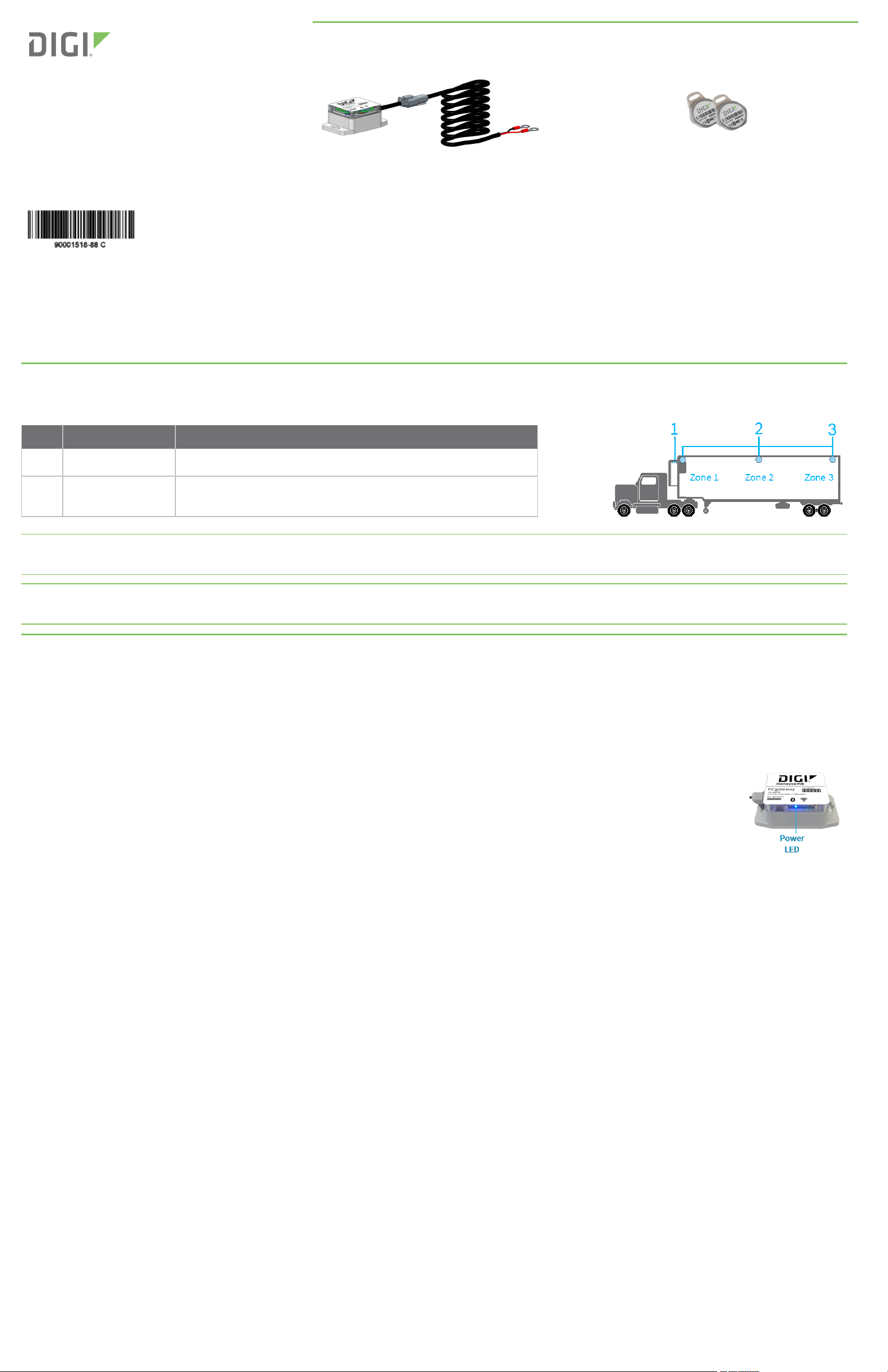
2 Follow installation guidelines
The following table describes where to install each Smart Gateway component, as it relates to a 3-zone installation.
Item Name Notes
1
Smart Gateway Installed in the refrigeration unit and powered by the battery.
2
HCtemp Sensor(s)
Installed in the zones of your trailer. The image on the right
shows an example of a 3-zone trailer.
HCtemp Sensor(s)
Note Operate only indoor when used in band 5150-5250 MHz to reduce the potential for harmful
interference to co-channel mobile satellite systems.
Note High-power radars are allocated as primary users (that is, priority users) of bands 5250-5350 MHz and 5650-5850 MHz and that these
radars could cause interference and/or damage to LE-LAN devices.
3 Install the Smart Gateway
Install the Smart Gateway on the inside of the refrigeration cabinet or on the external wall of the trailer next to the refrigeration cabinet.
To install the Smart Gateway inside of the refrigeration cabinet:
Secure the Smart Gateway toward the top of the cabinet and make sure it is stable and cannot move or come loose.
a. Connect the 3/8 inch ring terminals to the 12 V battery terminals in the refrigeration unit.
Note: The red wire connects to the positive (+) terminal of the battery. The black wire connects to the battery ground (-).
b. Verify the Smart Gateway power LED:
n Solid blue LED on Legacy (non-cellular) gateways indicates power.
n Solid green LED on Late Model (cellular) gateways indicates power.
If NO POWER, make sure the cable ring terminals are securely connected to the battery.
c. Run the cable along the inside wall of the refrigeration unit and use zip ties to secure excess cable length.
d. Use screws to secure the Smart Gateway high up and on the inside of the refrigeration cabinet. Typically, you can secure it to a crossbar.
Verify that the Smart Gateway is tightly fastened so that it cannot move or come loose.
e. Make note of the Smart Gateway ID(such as A001234) and the trailer ID it is installed in. You will need this information for updating the
Digi Host with the Trailer Number/ID information.
To install the Smart Gateway on the exterior wall (outside of the reefer cabinet):
Secure the Smart Gateway to the exterior wall of the trailer using machine tap screws.
a. Mark the mounting hole locations.
b. Drill a pilot hole for the tap screws.
c. Apply silicone sealant to the pilot holes.
d. Mount the Smart Gateway to the trailer wall using the tap screws.
e. Run the cable along the wall of the refrigerator unit and use zip ties to secure excess cable length.
f. Connect the 3/8 inch ring terminals to the 12 V battery terminals in the refrigeration unit.
Note: The red wire connects to the positive (+) terminal of the battery. The black wire connects to the battery ground (-).
© 2017 Digi International Inc.
Digi, Digi International, and the Digi logo are trademarks or registered trademarks in the United States and other countries worldwide. All other trademarks mentioned in this
document are the property of their respective owners.
Page 2

g. Verify the Smart Gateway power LED:
n Solid blue LED on Legacy (non-cellular) gateways indicates power.
n Solid green LED on Late Model (cellular) gateways indicates power.
If NO POWER, make sure the cable ring terminals are securely connected to the battery.
h. Make note of the Smart Gateway ID(such as A001234) and the trailer ID it is installed in. You will need this information for updating the
Digi Host with the Trailer Number/ID information.
4 Install the temperature sensors
Install the temperature sensors inside and toward the top of the trailer, away from the load or other objects that could knock them out of place.
a. Install an HCtemp sensor in the first zone of the trailer:
Note Install the HCtemp sensor with the lowest ID number into Zone 1 and the highest ID number into Zone 3. This allows the system to
auto-configure the order of installed sensors.
n Use a zip tie or screw to secure the sensor high in the box and as close to the refrigeration unit as possible, such as on a
refrigeration line.
n Make note of the HCtemp sensor ID, corresponding Smart Gateway, trailer ID, and its location (for example, Zone 1 or Trailer
Nose).
b. Install additional HCtemp sensors for each zone of the trailer:
n Use a zip tie or screw to secure the sensor high in the box, in the middle or end of the zone.
n Make note of the HCtemp sensor ID, its corresponding Smart Gateway, trailer ID, and location (for example, Zone 1, Zone 2, or
Zone 3).
The Smart Gateway trailer package is now installed.
5 Next steps
For additional guides, videos, and order forms, visit www.digi.com/cold-chain-solutions.
For help with your Smart Gateway system:
n Call (U.S. or Canada): 866.806.COLD (2653)
n Email:
coldchainsupport@digi.com
Regulatory statement
RF Exposure Statement
To comply with RF exposure limits established in the ANSI C95.1 standards, the distance between the antenna or antennas and the user should
not be less than 20 cm.
FCC Certifications and Regulatory Information (USA only)
FCC Part 15 Class B
This device complies with part 15 of the FCC Rules. Operation is subject to the following two conditions:
1. This device may not cause harmful interference, and
2. This device must accept any interference received, including interference that may cause undesired operation.
Changes or modifications made to this equipment not expressly approved by the party responsible for compliance could void the user's
authority to operate the equipment.
Radio Frequency Interface (RFI) (FCC 15.105)
This device has been tested and found to comply with the limits for Class B digital devices pursuant to Part 15 Subpart B, of the FCC rules. These
limits are designed to provide reasonable protection against harmful interference in a residential environment. This equipment generates, uses,
and can radiate radio frequency energy, and if not installed and used in accordance with the instruction manual, may cause harmful
interference to radio communications. However, there is no guarantee that interference will not occur in a particular installation. If this
equipment does cause harmful interference to radio or television reception, which can be determined by turning the equipment off and on, the
user is encouraged to try and correct the interference by one or more of the following measures:
n Reorient or relocate the receiving antenna.
n Increase the separation between the equipment and receiver.
n Connect the equipment into an outlet on a circuit different from that to which the receiver is connected.
n Consult the dealer or an experienced radio/TV technician for help.
When this device is used in band 5150-5250 MHz, operate only indoor to reduce the potential for harmful interference to co-channel mobile
satellite systems.
High-power radars are allocated as primary users (that is, priority users) of bands 5250-5350 MHz and 5650-5850 MHz and that these radars
could cause interference and/or damage to LE-LAN devices.
Page 3

Industry Canada (IC) Certifications
This device complies with Industry Canada’s licence-exempt RSSs. Operation is subject to the following two conditions:
1. This device may not cause interference; and
2. This device must accept any interference, including interference that may cause undesired operation of the device.
Le présent appareil est conforme aux CNR d'Industrie Canada applicables aux appareils radio exempts de licence. L'exploitation est autorisée
aux deux conditions suivantes :
1. L'appareil ne doit pas produire de brouillage, et
2. L'utilisateur de l'appareil doit accepter tout brouillage radioélectrique subi, même si le brouillage est susceptible d'en compromettre le
fonctionnement.
 Loading...