

Page 1

SERVICE MANUAL
PC SCALE PRINTER
SM-5500 SERIES
SM-5000BS
Edition 3
COPYRIGHT © 2010 TERAOKA WEIGH-SYSTEM PTE LTD
Page 2

Table of Content
i) Notice 1
ii) Safety Information.....................................................................................................................................2
iii) Safety Regulations...................................................................................................................................3
iv) Treatment And Recovery of WEEE.........................................................................................................4
1. GENERAL ......................................................................................................................................................10
1.1 Model Specification ............................................................................................................................10
1.2 Operating Specification ......................................................................................................................12
1.3 Overall Dimension (in mm).................................................................................................................13
1.3.1 Bench (B)..............................................................................................................................13
1.3.2 Pole (P).................................................................................................................................14
1.3.3 Elevated (With 2nd Printer) (EV)............................................................................................15
1.3.4 Elevated (Without 2nd Printer) (EV).......................................................................................16
1.3.5 Elevated Electroluminescent Display (With 2nd Printer) (EVEL)..........................................17
1.3.6 Elevated Electroluminescent Display (Without 2nd Printer) (EVEL)......................................18
1.3.7 Elevated PLUS (With 2nd Printer) (EV-PLUS).......................................................................19
1.3.8 Elevated PLUS (Without 2nd Printer) (EV-PLUS)..................................................................20
1.3.9 Pole Electroluminescent Display (PEL) ................................................................................21
1.3.10 Self-Service (SM-5000BS)..................................................................................................22
1.4 Label & Receipt Specifications...........................................................................................................23
1.4.1 Base Printer ..........................................................................................................................23
1.4.2 2nd Printer Receipt Paper......................................................................................................24
2. KEY SHEET AND DISPLAY..........................................................................................................................24
2.1 Key Sheet Layout And Key Function..................................................................................................24
2.1.1 Key Sheet Layout..................................................................................................................24
2.1.2 Key Function.........................................................................................................................25
2.2 Operator And Customer Display And Indicator Layout......................................................................26
2.2.1 Operator Display...................................................................................................................26
2.2.2 Customer Display..................................................................................................................27
3. SOFTWARE FUNTIONAL STRUCTURE......................................................................................................28
4. I/O PORTS, SPAN SWITCH AND W&M SEALING LOCATION...................................................................30
4.1 I/O Ports 30
4.2 Span Switch........................................................................................................................................30
4.3 Location of Sealing Screw/Sticker......................................................................................................31
5. INITIAL SETUP ..............................................................................................................................................33
5.1 Pole Assembly....................................................................................................................................33
5.1.1 SM-5500P.............................................................................................................................33
5.1.2 SM-5500EV...........................................................................................................................35
5.1.3 SM-5500EVEL ......................................................................................................................37
5.1.4 SM-5000BS...........................................................................................................................39
5.2 Level Adjustment................................................................................................................................41
5.3 AC Cord Mounting..............................................................................................................................41
5.4 Cassette Loading................................................................................................................................42
5.4.1 Label Printing........................................................................................................................42
5.4.2 Receipt Printing.....................................................................................................................42
5.4.3 Linerless Label Printing.........................................................................................................42
5.5 Software Setup...................................................................................................................................43
5.5.1 Default Country SPEC..........................................................................................................43
5.5.2 User SPEC............................................................................................................................46
5.5.3 Module SPEC........................................................................................................................48
5.5.4 Scale SPEC ..........................................................................................................................50
5.5.5 Weigh & Measure SPEC.......................................................................................................52
5.5.5.1 SEARCH Function Procedure:..............................................................................55
5.5.6 Date And Time......................................................................................................................57
Page 3

5.5.7 Daylight Saving Time............................................................................................................59
5.6 Span Adjustment (Weight Calibration)...............................................................................................61
6. SYSTEM SETUP ............................................................................................................................................63
6.1 Network Setup....................................................................................................................................63
6.1.1 IP Address Setup..................................................................................................................63
6.1.2 Database IP Address............................................................................................................64
6.1.3 Scale MAC Address..............................................................................................................67
6.1.4 WLAN (RF Bridge) Setup......................................................................................................68
6.2 Base Station (BS-02) Setup ...............................................................................................................72
6.2.1 Serial Port Configuration.......................................................................................................72
6.3 External SVGA Display Setup............................................................................................................73
7. HARDWARE TEST AND MAINTENANCE....................................................................................................77
7.1 Internal Count Mode...........................................................................................................................77
7.2 Printer Test.........................................................................................................................................78
7.2.1 Sensors Status......................................................................................................................78
7.2.2 Sensor Calibration.................................................................................................................80
7.2.3 Thermal Head Type Detection..............................................................................................84
7.3 Database Maintenance.......................................................................................................................85
7.3.1 Database Initialization...........................................................................................................85
7.3.2 Database Backup..................................................................................................................87
7.3.3 Database Restore.................................................................................................................88
7.3.4 Load Default Data.................................................................................................................90
7.3.5 Database Migration...............................................................................................................91
7.3.6 USB Backup / Restore..........................................................................................................92
7.3.6.1 USB Backup..........................................................................................................92
7.3.6.2 USB Restore.........................................................................................................94
7.4 Hardware Test....................................................................................................................................97
7.4.1 Input......................................................................................................................................97
7.4.2 USB.......................................................................................................................................98
7.4.3 RS232...................................................................................................................................99
7.4.4 Ethernet...............................................................................................................................100
7.4.5 Drawer.................................................................................................................................102
7.4.6 LCD.....................................................................................................................................103
7.5 Touch Screen Calibration.................................................................................................................106
7.6 Write AD Checksum.........................................................................................................................109
7.7 System Information...........................................................................................................................111
7.8 Maintenance.....................................................................................................................................113
7.8.1 Thermal Head Cleaning......................................................................................................113
7.8.2 Basic Cleaning....................................................................................................................114
8. FIRMWARE UPGRADING...........................................................................................................................115
8.1 Kernel 115
8.2 PC Scale Application........................................................................................................................122
8.3 Printer Firmware...............................................................................................................................123
9. MAJOR PARTS DISASSEMBLY.................................................................................................................127
9.1 SM-5500B.........................................................................................................................................127
9.1.1 Disassembly of Platter Support...........................................................................................127
9.1.2 Disassembly of CPU & Base Board....................................................................................128
9.1.3 Disassembly of Top Cover and Customer (LCD) Display...................................................129
9.1.4 Disassembly of Power Supply Unit and AD Board.............................................................130
9.1.5 Disassembly of Load Cell ...................................................................................................130
9.1.6 Disassembly of Display Board and Operator (8.4” TFT LCD) Display ...............................131
9.2 SM-5500P.........................................................................................................................................132
9.2.1 Disassembly of Platter Support...........................................................................................132
9.2.2 Disassembly of Pole Block..................................................................................................132
9.2.3 Disassembly of Customer (LCD) Display ...........................................................................134
Page 4

9.2.4 Disassembly of CPU & Base Board....................................................................................135
9.2.5 Disassembly of Top Cover..................................................................................................136
9.2.6 Disassembly of Power Supply Unit and AD Board.............................................................137
9.2.7 Disassembly of Load Cell ...................................................................................................137
9.2.8 Disassembly of Display Board and Operator (8.4” TFT LCD) Display ...............................138
9.3 SM-5500EV......................................................................................................................................139
9.3.1 Disassembly of Platter Support...........................................................................................139
9.3.2 Disassembly of Pole Block..................................................................................................139
9.3.3 Disassembly of Display Board and Operator (8.4” TFT LCD) Display ...............................141
9.3.4 Disassembly of Customer (LCD) Display ...........................................................................142
9.3.5 Disassembly of Receipt & Cutter Controller Board and 2nd Printer ....................................143
9.3.6 Disassembly of CPU & Base Board....................................................................................147
9.3.7 Disassembly of Top Cover..................................................................................................148
9.3.8 Disassembly of Power Supply Unit and AD Board.............................................................149
9.3.9 Disassembly of Load Cell ...................................................................................................149
9.4 SM-5500EVEL..................................................................................................................................150
9.4.1 Disassembly of Platter Support...........................................................................................150
9.4.2 Disassembly of Pole Block..................................................................................................150
9.4.3 Disassembly of Display Board and Operator (8.4” TFT LCD) Display ...............................152
9.4.4 Disassembly of Customer (EL) Display ..............................................................................155
9.4.5 Disassembly of Receipt & Cutter Controller Board and 2nd Printer ....................................156
9.4.6 Disassembly of CPU & Base Board....................................................................................158
9.4.7 Disassembly of Top Cover..................................................................................................159
9.4.8 Disassembly of Power Supply Unit and AD Board.............................................................160
9.4.9 Disassembly of Load Cell ...................................................................................................160
9.5 SM-5000BS......................................................................................................................................161
9.5.1 Disassembly of Platter Support...........................................................................................161
9.5.2 Disassembly of Pole Block..................................................................................................161
9.5.3 Disassembly of CPU & Base Board....................................................................................166
9.5.4 Disassembly of Top Cover..................................................................................................167
9.5.5 Disassembly of Power Supply Unit and AD Board.............................................................168
9.5.6 Disassembly of Load Cell ...................................................................................................168
10. HARDWARE DETAILS..............................................................................................................................169
10.1 Block Diagram................................................................................................................................169
10.1.1 Bench (B)..........................................................................................................................169
10.1.2 Pole (P).............................................................................................................................170
10.1.3 Elevated (EV)....................................................................................................................171
10.1.4 Elevated (EV) (Full Option)...............................................................................................172
10.1.5 Elevated Electroluminescent Display (EVEL)...................................................................173
10.1.6 Pole Electroluminescent Display (PEL) ............................................................................174
10.1.7 Elevated Plus (EV-PLUS).................................................................................................175
10.1.8 Elevated Remote...............................................................................................................176
10.1.9 Self-Service (BS)...............................................................................................................177
10.2 Power Supply Unit..........................................................................................................................178
10.3 CPU Board .....................................................................................................................................178
10.4 Base Board.....................................................................................................................................180
10.5 Touch Screen Board.......................................................................................................................181
11. OPTION KITS INSTALLATION .................................................................................................................182
11.1 WLAN Kits Installation....................................................................................................................182
11.2 12.1” Remote Display Installation...................................................................................................184
11.3 Base Station Installation.................................................................................................................187
12. PORT PIN CONFIGURATION AND CABLE.............................................................................................188
12.1 Ethernet Port ..................................................................................................................................188
12.2 RS232C Port ..................................................................................................................................189
12.3 USB Port.........................................................................................................................................189
12.4 Cash Drawer Port...........................................................................................................................190
Page 5

13. SPECIFICATION LIST ...............................................................................................................................191
13.1 W&M SPEC....................................................................................................................................191
13.1.1 W&M Scale .......................................................................................................................191
13.1.2 W&M Tare.........................................................................................................................192
13.1.3 W&M Price........................................................................................................................193
13.1.4 W&M Operation.................................................................................................................194
13.2 Printer SPEC..................................................................................................................................196
13.2.1 Printer 1 SPEC..................................................................................................................196
13.2.2 Printer 2 SPEC..................................................................................................................197
13.3 User SPEC.....................................................................................................................................198
13.3.1 Barcode.............................................................................................................................198
13.3.1.1 Item Barcode.....................................................................................................198
13.3.1.2 Total Item..........................................................................................................199
13.3.1.3 MultiBarcode.....................................................................................................200
13.3.2 Communication.................................................................................................................200
13.3.3 Label .................................................................................................................................200
13.3.3.1 Advertisement...................................................................................................200
13.3.3.2 Currency Symbol ..............................................................................................201
13.3.3.3 Data Fields........................................................................................................201
13.3.3.4 Field Title...........................................................................................................201
13.3.3.5 Ingredient..........................................................................................................201
13.3.3.6 Label Format.....................................................................................................202
13.3.3.7 Nutrition.............................................................................................................203
13.3.3.8 Other.................................................................................................................203
13.3.3.9 Quantity And Symbol........................................................................................204
13.3.3.10 Shop Name.....................................................................................................204
13.3.4 Receipt..............................................................................................................................204
13.3.4.1 General .............................................................................................................204
13.3.4.2 Talon.................................................................................................................205
13.3.4.3 Void Receipt......................................................................................................206
13.3.5 Settings.............................................................................................................................206
13.3.5.1 Accumulation & Change Mode .........................................................................206
13.3.5.2 Auto Entry & Reentry........................................................................................206
13.3.5.3 Auto PLU Call ...................................................................................................207
13.3.5.4 Auto Printing .....................................................................................................207
13.3.5.5 Barcode Scanner..............................................................................................207
13.3.5.6 Cash Drawer.....................................................................................................207
13.3.5.7 CCD ..................................................................................................................207
13.3.5.8 Commodity Name Shown.................................................................................208
13.3.5.9 Continues Printing.............................................................................................208
13.3.5.10 Cool.................................................................................................................208
13.3.5.11 Customer.........................................................................................................208
13.3.5.12 Date Time Format...........................................................................................208
13.3.5.13 Discount..........................................................................................................209
13.3.5.14 EL Display.......................................................................................................209
13.3.5.15 Email...............................................................................................................209
13.3.5.16 Force Quantity ................................................................................................210
13.3.5.17 Force Shelf Life...............................................................................................210
13.3.5.18 Function Key Related......................................................................................210
13.3.5.19 Hi-Touch..........................................................................................................210
Page 6

13.3.5.20 Image & Text...................................................................................................210
13.3.5.21 LCD Display....................................................................................................210
13.3.5.22 Log..................................................................................................................210
13.3.5.23 Manual Price Entry..........................................................................................210
13.3.5.24 Manual Weigh Entry........................................................................................210
13.3.5.25 Operator..........................................................................................................211
13.3.5.26 Order & Basket ...............................................................................................211
13.3.5.27 Other...............................................................................................................211
13.3.5.28 Password ........................................................................................................212
13.3.5.29 PLU Grouping.................................................................................................212
13.3.5.30 Reset...............................................................................................................213
13.3.5.31 Report .............................................................................................................213
13.3.5.32 Self Service.....................................................................................................213
13.3.5.33 Tare.................................................................................................................213
13.3.5.34 Traceability......................................................................................................214
13.3.5.35 Unit Price Override..........................................................................................214
13.3.5.36 Unit Price Recalculation..................................................................................215
13.4 Module SPEC.................................................................................................................................216
13.4.1 Password ..........................................................................................................................216
13.4.2 E-label & Hi-Touch............................................................................................................216
13.4.3 Queue System & Turn Chime...........................................................................................216
13.4.4 Other.................................................................................................................................217
13.5 Scale SPEC....................................................................................................................................218
13.5.1 Scale Price........................................................................................................................218
13.5.2 Scale Tare.........................................................................................................................218
13.5.3 Scale Tax..........................................................................................................................218
13.5.3 Scale Operation ................................................................................................................219
14. REVISION RECORDS................................................................................................................................220
Page 7

i) Notice
DIGI®
The material contained in this document is proprietary and for information only and is subject to change without
notice. Teraoka Weigh-System Pte Ltd assumes no responsibility for any errors or damages arising from
misinterpretation of any procedure.
Screen displays, operating procedures and supporting features might vary with different software version
releases.
This document shall not be reproduced whether in part or whole without the written consent from Teraoka
Weigh-System Pte Ltd.
Teraoka Weigh-System Pte Ltd
4, Leng Kee Road
#06-01 SIS Building
Singapore 159088
1
Page 8

ii) Safety Information
The operator of the equipment shall comply with the safety and warning indications and procedures outlined in
this document. Teraoka Weigh-System Pte Ltd assumes no responsibility or liability for failure to comply with
these requirements.
• To avoid electric shock, use only the supplied power cords and ensure product is connected to a
properly grounded supply.
• Ensure product is placed on a firm and level surface before operation.
• Avoid overloading the product beyond its rated maximum capacity.
• Care shall be taken during the following operations
o Receipt paper tearing – to prevent injuries from cutting from paper cutter
o Changing of labels and receipt paper - to prevent injuries from cutting from paper cutter and
movable printer mechanism.
• Repair and servicing of product, shall only be carried out by trained and qualified personnel.
Disclaimer:
Specifications are subject to change without notice. All dimensions shown are approximate. Please be aware
that Teraoka Weigh-System Pte Ltd has indicated that its hardware and software used in the product may
require additional updates in the future as our product is continually under development. The need for such
updates most likely applies to the Printer software.
CAUTIONS:
FOR PLUGGABLE EQUIPMENT, THAT THE SOCKET-OUTLET SHALL BE INSTALLED NEAR THE
EQUIPMENT AND SHALL BE EASILY ACCESSIBLE.
POUR LE MATÉRIEL RACCORDÉ PAR PRISE DE COURANT, LE SOCLE DE PRISE DE
COURANT DOIT ÊTRE
INSALLÉ À PROXIMITÉ DU MATÉRIEL ET DOIT ÊTRE AISÉMENT ACCESSIBLE.
FOR CONTINUED PROTECTION AGAINST RISK OF FIRE, REPLACE ONLY WITH SAME TYPE
AND RATING OF FUSE.
POUR NE PAS COMPROMETTRE LA PROTECTION CONTRE LES RISQUES D’INCENDIE,
REMPLACER PAR UN FUSIBLE DE MÊME TYPE ET DE MÊME CARACTÉRISTIQUES
NOMINALES.
DANGER OF EXPLOSION IF BATTERY IS INCORRECTLY REPLACED. REPLACE ONLY WITH
THE SAME OR EQUIVALENT TYPE RECOMMENDED BY THE MANUFACTURER. DISCARD
USED BATTERIES ACCORDING TO THE MANUFACTURER’S INSTRUCTIONS
IL Y A DANGER D’EXPLOSION S’IL Y A REMPLACEMENT INCORRECT DE LA BATTERIE.
REMPLACER UNIQUEMENT AVEC UNE BATTERIE DU MÊME TYPE OU D’UN TYPE
RECOMMANDÉ PAR LE CONSTRUCTEUR. METTRE AU RÉBUT LES BATTERIES USAGÉES
CONFORMÉMENT AUX INSTRUCTIONS DU FABRICANT.
WARNING DISPOSAL:
THE BATTERY MAY BE REGULATED BY NATIONAL OR LOCAL REGULATION. PLEASE FOLLOW
THE INSTRUCTIONS OF PROPER REGULATION. AS ELECTRIC CAPACITY IS LEFT IN A
DISCARDED BATTERY AND IT COMES INTO CONTACT WITH OTHER METALS, IT COULD LEAD TO
DISTORTION, LEAKAGE, OVERHEATING, OR EXPLOSION, SO MAKE SURE TO CUT/BREAK THE
BATTERY LEGS AND COVER THE (+) AND (-) TERMINALS WITH FRICTION TAPE OR SOME OTHER
INSULATOR BEFORE DISPOSAL.
Cut / Break the Battery
Legs
Tape
-
+
Battery
2
Page 9

iii) Safety Regulations
Federal Communication Commission Interference Statement
This equipment has been tested and found to comply with the limits for a Class B digital device, pursuant to
Part 15 of the FCC Rules. These limits are designed to provide reasonable protection against harmful
interference in a residential installation. This equipment generates uses and can radiate radio frequency energy
and, if not installed and used in accordance with the instructions, may cause harmful interference to radio
communications. However, there is no guarantee that interference will not occur in a particular installation. If
this equipment does cause harmful interference to radio or television reception, which can be determined by
turning the equipment off and on, the user is encouraged to try to correct the interference by one of the
following measures:
- Reorient or relocate the receiving antenna.
- Increase the separation between the equipment and receiver.
- Connect the equipment into an outlet on a circuit different from that to which the receiver is connected.
- Consult the dealer or an experienced radio/TV technician for help.
This device complies with Part 15 of the FCC Rules. Operation is subject to the following two conditions: (1)
This device may not cause harmful interference, and (2) this device must accept any interference received,
including interference that may cause undesired operation.
FCC Caution: Any changes or modifications not expressly approved by the party responsible for compliance
could void the user's authority to operate this equipment.
IMPORTANT NOTE:
FCC Radiation Exposure Statement:
This equipment complies with FCC RF radiation exposure limits set forth for an uncontrolled environment. To
maintain compliance with FCC RF exposure compliance requirements, please avoid direct contact to the
transmitting antenna during transmitting.
3
Page 10

iv) Treatment And Recovery of WEEE
Component listing of Hazardous Material
To all user of DIGI product in the European Union
Thank you for using DIGI product.
Product marked with this symbol indicates that it was sold on or after 13th August 2005, which means it should
not be disposed of with general household waste. Please note that our product is for industrial/professional use
only.
Treatment and recovery of WEEE involves removing hazardous substances (such as those covered in the
RoHS Directives) as well as PCBs and liquids. Only licensed operators meeting WEEE regulations will be able
to handle and recover WEEE.
Please contact your DIGI office or DIGI distributor when the product has reached the end of its life. They will
advise you regarding the product take-back.
With your co-operation we are aiming to reduce environmental pollution from waste electrical and electronic
equipment and preserve natural resource through re-use and recycling. Please do not hesitate to ask your DIGI
office or DIGI distributor, if you require further information.
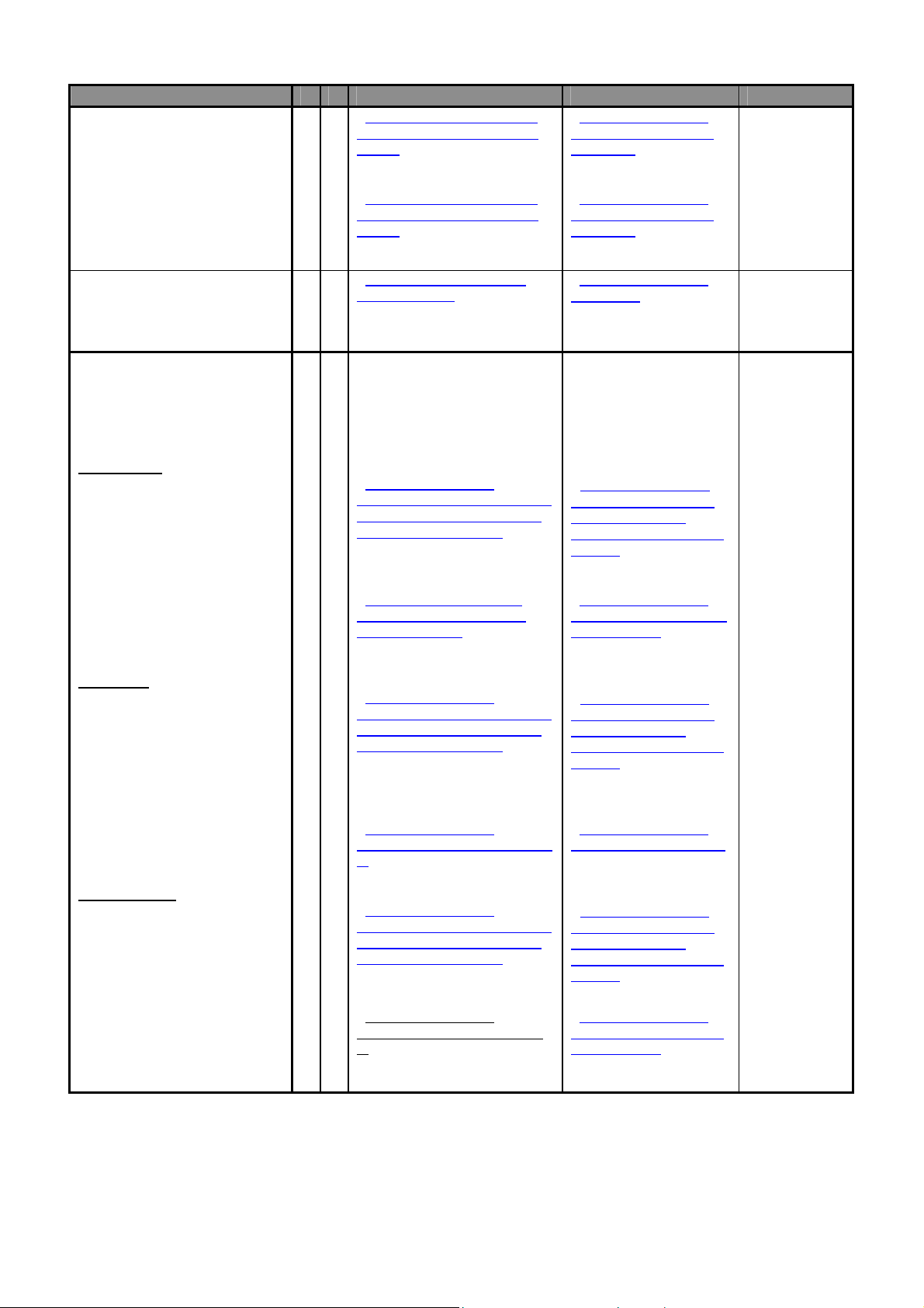
Items required to be removed from product at end of product life as listed in WEEE Annex II
Items Y N Identification Removal procedure Comments
o Fluids
o Polychlorinated biphenyls
(PCB) containing capacitors.
o Mercury containing
components, such as
switches or backlighting
lamps.
o Printed circuit boards of
mobile phones.
o Toner cartridges, liquid and
pasty, as well as color toner.
o Plastic containing
brominated flame-retardants.
o Asbestos waste.
o Cathode ray tubes.
o Chlorofluorocarbons (CFC),
hydro chlorofluorocarbons
(HCFC) orhydrofluorocarbons
(HFC), hydrocarbons (HC).
o Gas discharge lamps.
o Components containing
4
Page 11

Items Y N Identification Removal procedure Comments
refractory ceramic fibred as
described in Commission
Directive 97/69/EC of 5
December 1997.
o
o Components containing
radioactive substances.
o
o External electric cables.
o
o Batteries.
1. Lithium Battery.
o Other printed circuit boards
greater than 10 square
centimeters.
Bench (B):
1) CPU Board
2) Base Board
3) AD Board
4) Power Unit
5) Display Board
AC Power Cord.
- 9.1.2 Disassembly of CPU
and Base Board – Item 1.
-
9.1.2 Disassembly of CPU
and Base Board – Item 2.
- 9.1.4 Disassembly of Power
Unit and AD Board – Item 3.
- 9.1.4 Disassembly of Power
Unit and AD Board – Item 4.
- 9.1.6 Disassembly of Display
Board and Operator (8.4” TFT
LCD) Display Item 5.
-
9.1.6 Disassembly of
CPU and Base Board
- Remove the Battery
from Base Board location
BT1.
9.1.2 Disassembly of
-
CPU and Base Board.
(Step 1 ~ 2)
Refer to Safety
Information
Warning
Disposal
-
9.1.2 Disassembly of
CPU and Base Board.
(Step 1 ~ 2)
- 9.1.1 Disassembly of
Platter Support,
9.1.3 Disassembly of
-
Top Cover and Customer
(LCD) Display.
(Step 1 ~ 2)
-
9.1.4 Disassembly of
Power Unit and AD
Board.
- 9.1.1 Disassembly of
Platter Support,
9.1.3 Disassembly of
-
Top Cover and Customer
(LCD) Display.
(Step 1 ~ 2)
- 9.1.4 Disassembly of
Power Unit and AD
Board.
- 9.1.6 Disassembly of
Key_Scan & TS Board,
Inverter Board and
Operator (8.4” TFT LCD)
Display.
5
Page 12

Items Y N Identification Removal procedure Comments
Pole (P):
1) CPU Board
2) Base Board
3) AD Board
4) Power Unit
- 9.2.4 Disassembly of CPU
and Base Board – Item 1.
- 9.2.4 Disassembly of CPU
and Base Board – Item 12
- 9.2.6 Disassembly of Power
Supply Unit and AD Board –
Item 3.
- 9.2.6 Disassembly of Power
Supply Unit and AD Board –
Item 4
9.2.4 Disassembly of
-
CPU and Base Board.
(Step 1 ~ 2)
- 9.2.4 Disassembly of
CPU and Base Board.
(Step 1 ~ 2)
- 9.2.6 Disassembly of
Power Supply Unit and
AD Board.
- 9.2.6 Disassembly of
Power Unit and AD
Board.
5) Display Board
Elevated (EV):
1) CPU Board
2) Base Board
3) AD Board
- 9.2.8 Disassembly of Display
Board and Operator (TFT 8.4”
LCD) Display – Item 5
- 9.3.6 Disassembly of CPU
and Base Board – Item 1.
- 9.3.6 Disassembly of CPU
and Base Board – Item 2.
-
9.3.8 Disassembly of Power
Unit & AD Board - Item 3.
- 9.2.8 Disassembly of
Display Board and
Operator (TFT 8.4” LCD)
Display.
(Step 1 ~ 2)
- 9.3.6 Disassembly of
CPU and Base Board.
(Step 1 ~ 2)
- 9.3.6 Disassembly of
CPU and Base Board.
(Step 1 ~ 2)
- 9.3.1 Disassembly of
Platter Support,
- 9.3.2 Disassembly of
Pole Block.
(Step 1 ~ 2)
- 9.3.7 Disassembly of
Elevated Type Top
Cover.
(Step 1 ~ 2)
9.3.8 Disassembly of
-
Power Unit & AD Board.
4) Power Unit
-
9.3.8 Disassembly of Power
Unit & AD Board - Item 4.
6
- 9.3.1 Disassembly of
Platter Support,
- 9.3.2 Disassembly of
Pole Block.
(Step 1 ~ 2)
- 9.3.7 Disassembly of
Elevated Type Top
Cover.
(Step 1 ~ 2)
9.3.8 Disassembly of
-
Power Unit & AD Board.
Page 13

Items Y N Identification Removal procedure Comments
5) Display Board
Elevated
Electroluminescent Display
(EVEL):
1) CPU Board
2) Base Board
3) AD Board
4) Power Unit
5) Display Board
SM-5000BS:
1) CPU Board
- 9.3.3 Disassembly of
Key_Scan & TS Board, Inverter
Board and Operator (8.4” TFT
LCD) Display – Item 5.
- 9.4.6 Disassembly of CPU &
Base Board Item 1.
- 9.4.6 Disassembly of CPU &
Base Board Item 2.
- 9.4.8 Disassembly of Power
Supply Unit And AD Board
Item 3.
- 9.4.8 Disassembly of Power
Supply Unit And AD Board
Item 4.
- 9.4.3 Disassembly of
Key_Scan & TS Board, Inverter
Board And Operator Display
Item 5.
9.5.3 Disassembly of CPU &
-
Base Board Item 1.
- 9.3.3 Disassembly of
Key_Scan & TS Board,
Inverter Board and
Operator (8.4” TFT LCD)
Display.
(Step 1 ~ 2)
- 9.4.6 Disassembly of
CPU & Base Board.
(Step 1 ~ 2)
- 9.4.6 Disassembly of
CPU & Base Board.
(Step 1 ~ 2)
- 9.4.1 Disassembly of
Platter Support,
- 9.4.2 Disassembly of
Pole Block.
(Step 1 ~ 2)
- 9.4.7 Disassembly of
Elevated Type Top
Cover.
(Step 1 ~ 2)
9.4.8 Disassembly of
-
Power Unit & AD Board.
- 9.4.1 Disassembly of
Platter Support,
- 9.4.2 Disassembly of
Pole Block.
(Step 1 ~ 2)
- 9.4.7 Disassembly of
Elevated Type Top
Cover.
(Step 1 ~ 2)
- 9.4.8 Disassembly of
Power Unit & AD Board.
- 9.4.3 Disassembly of
Key_Scan & TS Board,
Inverter Board And
Operator Display.
(Step 1 ~ 5)
9.5.3 Disassembly of
-
CPU & Base Board.
(Step 1 ~ 2)
2) Base Board
- 9.5.3 Disassembly of CPU &
Base Board Item 2.
7
9.5.3 Disassembly of
-
CPU & Base Board.
(Step 1 ~ 2)
Page 14
Items Y N Identification Removal procedure Comments
3) AD Board
4) Power Unit
5) Display Board
o Liquid crystal displays
(together with their casing
where appropriate) of a
surface greater than 100 cm2
and all those back-lighted with
gas discharge lamps.
Bench Type:
1) LCD (Operator Display)
2) LCD (Customer Display)
Pole Type:
1) LCD (Operator Display)
2) LCD (Customer Display)
Elevated Type:
1) LCD (Operator Display)
2) LCD (Customer Display)
- 9.5.5 Disassembly of Power
Supply Unit And AD Board
Item 3.
- 9.5.5 Disassembly of Power
Supply Unit And AD Board
Item 4.
- 9.5.2 Disassembly of Pole
Block Item 5.
9.1.6 Disassembly of
-
Key_Scan & TS Board, Inverter
Board and Operator (8.4” TFT
LCD) Display Item 6.
- 9.1.3 Disassembly of Top
Cover and Customer (LCD)
Display Item 7.
- 9.2.8 Disassembly of
Key_Scan & TS Board, Inverter
Board and Operator (8.4” TFT
LCD) Display Item 6.
9.2.3 Disassembly of
-
Customer (LCD) Display Item
7.
9.3.3 Disassembly of
-
Key_Scan & TS Board, Inverter
Board and Operator (8.4” TFT
LCD) Display Item 6.
- 9.3.4 Disassembly of
Customer (LCD) Display (Item
7.
- 9.5.5 Disassembly of
Power Supply Unit And
AD Board.
- 9.5.5 Disassembly of
Power Supply Unit And
AD Board.
9.5.2 Disassembly of
-
Pole Block.
(Step 7 ~ 8)
- 9.1.6 Disassembly of
Key_Scan & TS Board,
Inverter Board and
Operator (8.4” TFT LCD)
Display.
- 9.1.3 Disassembly of
Top Cover and Customer
(LCD) Display.
- 9.2.8 Disassembly of
Key_Scan & TS Board,
Inverter Board and
Operator (8.4” TFT LCD)
Display.
-
9.2.3 Disassembly of
Customer (LCD) Display.
9.3.3 Disassembly of
-
Key_Scan & TS Board,
Inverter Board and
Operator (8.4” TFT LCD)
Display.
- 9.3.4 Disassembly of
Elevated Type Customer
(LCD) Display.
8
Page 15

Items Y N Identification Removal procedure Comments
EVEL Type:
1) LCD (Operator Display)
2) Luminescent LCD (Customer
Display)
BS Type:
1) LCD (Operator Display)
9.4.3 Disassembly of
-
Key_Scan & TS Board, Inverter
Board and Operator (8.4” TFT
LCD) Display Item 6.
- 9.4.4 Disassembly of
Customer Display Item 8.
-
9.5.2 Disassembly of Pole
Block Item 6.
9.4.3 Disassembly of
-
Key_Scan & TS Board,
Inverter Board and
Operator (8.4” TFT LCD)
Display.
- 9.4.4 Disassembly of
Customer Display.
-
9.5.2 Disassembly of
Pole Block.
(Step 7 ~ 9)
9
Page 16

1. GENERAL
1.1 Model Specification
Model
Variation
CPU
System
Memory
SM-5500
:
Description:
:
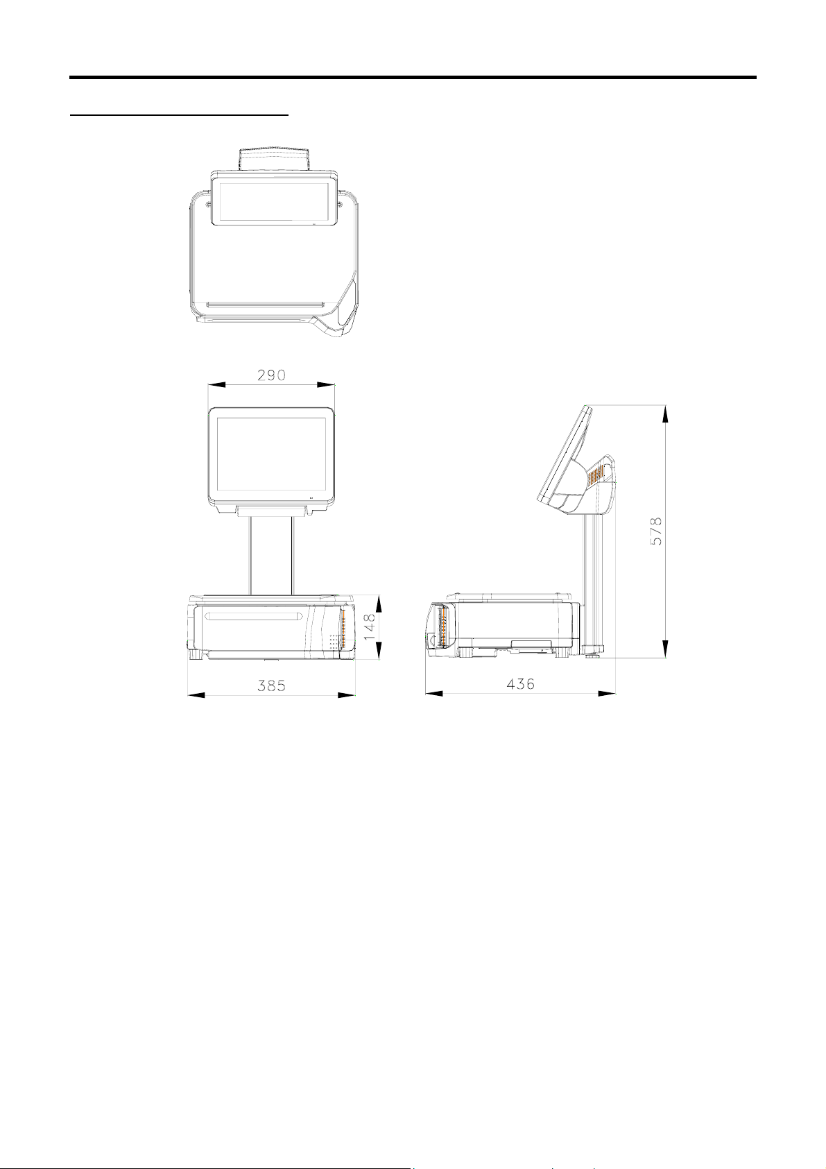
Bench - SM-5500B - 446 (adjustable) x 385 x 148
Pole - SM-5500P Elevated (with 2
Elevated (without 2
Elevated Electroluminescent
Display (Without 2
Elevated Electroluminescent
Display (With 2
Elevated Plus (With 2
Elevated Plus (Without 2
Printer)
Pole Electroluminescent Display - SM-5500PEL - 508 x 385 x 410
Self-Service (Without 2
Printer)
IMX31 533MHz
:
On Board 512MB DDR SDRAM 133MHz
:
SM-5500 Series & SM-5000BS Service Manual 3rd Edition
Type: Dimension (DxWxH in mm):
531 (adjustable) x 385 x 581
nd
Printer) - SM-5500EV -
nd
Printer) - SM-5500EV - 470 x 385 x 511
- SM-5500EVEL -
nd Printer)
SM-5500EVEL
-
nd Printer)
nd
Printer) - SM-5500EVPLUS - 480 (adjustable) x 385 x 471
nd
nd
- SM-5500EVPLUS - 469 (adjustable) x 385 x 426
- SM-5000BS - 436 x 385 x 578
482 x 385 x 517
470 x 385 x 567
481 x 385 x 638
-
SD Card
Operating
System
Capacity
Accuracy
Display
:
2GB & above
LINUX
:
6kg (less than 3kg, e = 1g / more than 3kg, e = 2g)
:
15kg (less than 6kg, e= 2g / more than 6kg, e = 5g)
:
30kg (less than 15kg, e = 5g / more than 15kg, e = 10g)
:
30lb (less than 15lb, e = 0.005lb / more than 30lb, e = 0.01lb)
:
Internal resolution 1/60000
:
Display resolution 1/3000 (Multi-Interval)
:
B / P / EV
:
EVEL
EV Plus
Operator
8.4” TFT VGA with Touch Panel 264 x 64 dots STN LCD 3 color
-
8.4” TFT VGA with Touch Panel 256 x 120 dots EL Display Panel
-
8.4” TFT VGA with Touch Panel 12.1” TFT SVGA LCD
-
Customer
10
Page 17

SM-5500 Series & SM-5000BS Service Manual 3rd Edition
Printing
BS
: Base Printer
Print Media
Paper Width
Print Speed
Max Roll Diameter
Thermal Head Life
nd
: 2
Printer (Option on EV model only)
Print Media
Print Width
Print Speed
Max Roll Diameter
Paper Thickness
Thermal Head Life
Cutter Life
Pattern Roller
12.1” TFT SVGA LCD with Touch
-
Panel
-
-
-
* Subject to the sensitivity of print media
-
-
-
-
-
* Subject to the sensitivity of print media
-
-
-
-
-
Engagement Life
Barcode
Symbol Scanner SE4500
:
Scanner
(Optional)
I/O Interface
Optional
1 x Ethernet 10/100 Base T
:
2 x RS-232 ports
:
1 x RJ11 Cash Drawer
:
1 x USB V2.0
:
1 x SD socket
:
Wi-Fi AP2001g
:
Interface
*Specifications are subject to change without notice
External SVGA Display (not applicable on Electroluminescent Display models)
:
----
Label with liner and linerless, Receipt paper
Maximum 80mm (Label & Receipt)
150mm/s* (Label with liner and linerless, Receipt paper)
φ125 mm
100km abrasion life / 100 million pulse (heater IC life)
Receipt paper
76mm
150mm/s*
φ100mm
60µm – 75µm
100km abrasion life / 100 million pulse (heater IC life)
1 million cuts
More then 10,000 times
(Recommend receipt roll OD (80mm) & Core (20mm) about
Length (80m) able to support)
11
Page 18

1.2 Operating Specification
Power Source
Frequency
Operating
AC Supply 100V / 230V (Selectable by Power Unit Jumper Setting)
:
50 / 60Hz
:
-10 °C to +40 °C
:
Temperature
Operation
Humidity
*Specifications are subject to change without notice
15% to 85%RH
:
SM-5500 Series & SM-5000BS Service Manual 3rd Edition
12
Page 19

1.3 Overall Dimension (in mm)
1.3.1 Bench (B)
SM-5500 Series / SM-5000BS Service Manual 3rd Edition
13
Page 20

SM-5500 Series / SM-5000BS Service Manual 3rd Edition
1.3.2 Pole (P)
14
Page 21

SM-5500 Series / SM-5000BS Service Manual 3rd Edition
1.3.3 Elevated (With 2
nd
Printer) (EV)
15
Page 22

SM-5500 Series / SM-5000BS Service Manual 3rd Edition
1.3.4 Elevated (Without 2
nd
Printer) (EV)
16
Page 23

SM-5500 Series / SM-5000BS Service Manual 3rd Edition
1.3.5 Elevated Electroluminescent Display (With 2
nd
Printer) (EVEL)
17
Page 24

SM-5500 Series / SM-5000BS Service Manual 3rd Edition
1.3.6 Elevated Electroluminescent Display (Without 2
nd
Printer) (EVEL)
18
Page 25

SM-5500 Series / SM-5000BS Service Manual 3rd Edition
Adj
1.3.7 Elevated PLUS (With 2
nd
Printer) (EV-PLUS)
ustable
19
Page 26

SM-5500 Series / SM-5000BS Service Manual 3rd Edition
1.3.8 Elevated PLUS (Without 2
nd
Printer) (EV-PLUS)
Adjustable
20
Page 27

SM-5500 Series / SM-5000BS Service Manual 3rd Edition
1.3.9 Pole Electroluminescent Display (PEL)
21
Page 28
SM-5500 Series / SM-5000BS Service Manual 3rd Edition
1.3.10 Self-Service (SM-5000BS)
22
Page 29

SM-5500 Series_SM-5000BS Service Manual 3rd Edition
1.4 Label & Receipt Specifications
1.4.1 Base Printer
Outer diameter of rolls: Maximum 105mm
Inner diameter of rolls: Minimum 40mm
Wide of receipt: 80mm (Max.)
Wide of label: 80mm (Max.) (max width (liner) is 82mm and max width for printing is 80mm)
WIDE OF LABEL/RECEIPT
LABEL TYPE LABEL SIZE PCS/ROLL
T1
T2
T3
T4/T10
T5/T11
T6
T7/T12
T8
T9
S
A / B
C
F1 – F99
(Free format)
80 (max) x 120 (max) -
60 x 28 1400
60 x 31 1300
60 x 34 1200
60 x 40 1000
60 x 43 960
60 x 46 900
60 x 49 840
60 x 55 750
60 x 37 1100
40 x 28 1400
40 x 46 900
40 x 62 670
REMARKS:
i) LABEL SIZE is in Width X Length and in millimeter unit.
ii) F1 to F99 is self-design free format label. Please note the minimum and maximum size.
23
Page 30
SM-5500 Series_SM-5000BS Service Manual 3rd Edition
1.4.2 2
nd
Printer Receipt Paper
Outer diameter of rolls: Maximum 80mm
Inner diameter of rolls: Minimum 12mm
Wide of receipt: Maximum 80mm
WIDE OF RECEIPT
2. KEY SHEET AND DISPLAY
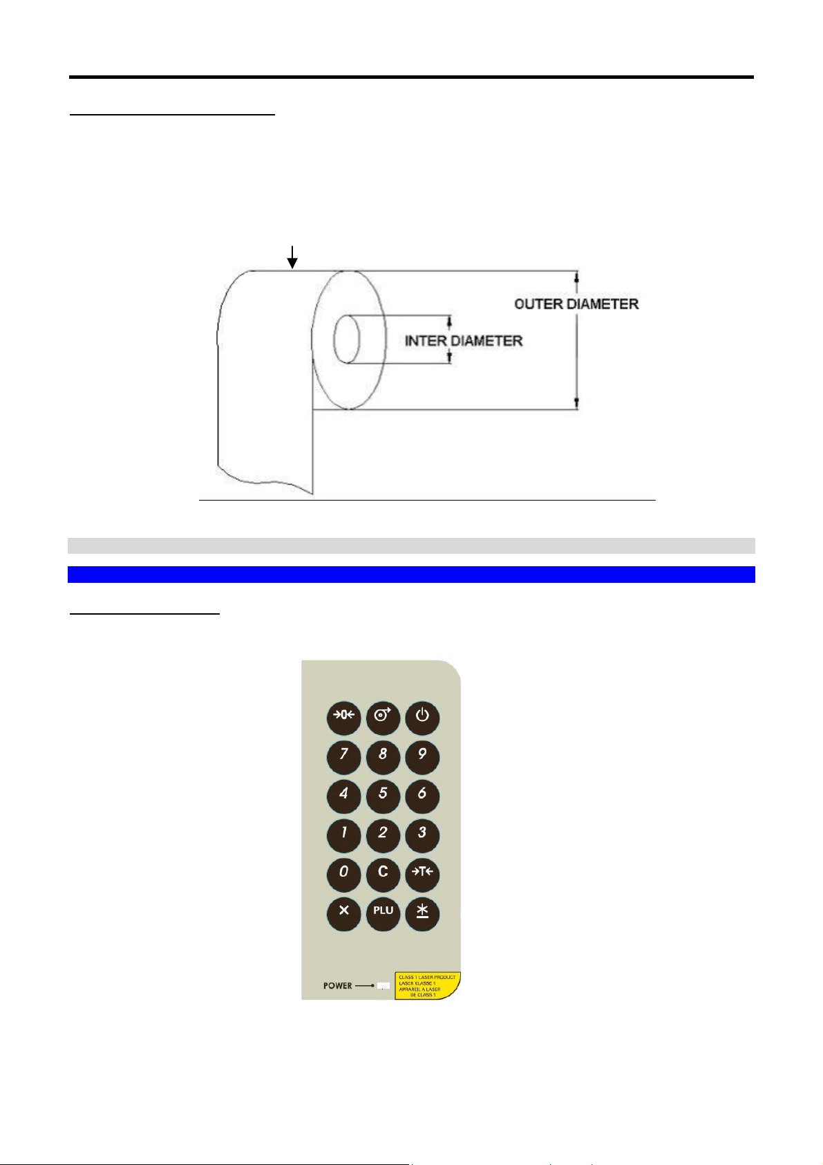
2.1 Key Sheet Layout And Key Function
2.1.1 Key Sheet Layout
*Actual legends and symbols may differ depending on local regulations and requirements.
24
Page 31

SM-5500 Series_SM-5000BS Service Manual 3rd Edition
2.1.2 Key Function
Refer to the followings for detail explanation for each key on the key panel.
Symbol Key Represent Key Function
ON/ OFF Key Turn on/off the display.
0-9 key Enter numeric data.
to
REZERO Key Reset weight to "0".
TARE Key Set or Clear the tare value.
CLEAR Key Clear entered data.
PLU Key
Calling up PLU in Registration mode.
Used as ENTER key in programming mode.
Multiply the number for non-weighing
MULTIPLY Key
product.
Used as ESCAPE key in Programming mode
PRINT Key Printing label or receipt in Registration mode.
FEED Key Feed label or receipt.
25
Page 32

SM-5500 Series_SM-5000BS Service Manual 3rd Edition
2.2 Operator And Customer Display And Indicator Layout
2.2.1 Operator Display
1 5
2 3
6
7
8
9
10
No. Area /Function USAGE
1
2
3
4
5
6
7
8
9
10
11
12
13
14
15
16
17
18
Preset Tare Display
Weight Display
Price Display
Total Price Display
Zero Indicator
Net Indicator
Mode Status Indicator
Commodity Name
Preset keys
Previous Page keys
Next Page keys
Function keys
Prepack/Manual key
Display Preset Tare
Display Weight value
Display Unit Price
Display Total Price
Display when Scale is stable at the zero point
Display when Tare Subtraction is being performed
Indicate the current status (Manual Mode or Prepack Mode)
Shows the Commodity Name of the called up PLU
Used for calling up PLUs / Function keys
Turn to previous page of Preset / Function keys
Turn to next page of Preset / Function keys
Used for calling up Clerk / Function keys
Toggle between Prepack Mode and Manual Mode
Menu key Return to MENU MODE Screen
Message Display Shows operation instructions
Scale Description Display the Scale description
Scale Indicator Shows S when Scale is configure SERVER
Shows C when Scale is configure CLEINT
Shows L when Client is OFF LINE
Date & Time Show the current Date and Time.
18
13
4
17
12
11
14
26
Page 33

SM-5500 Series_SM-5000BS Service Manual 3rd Edition
REMARKS:
1) PREV & NEXT keys will appears when there is more than 1 page of Preset/Function keys.
2) When in Prepack Mode, the Function keys at the bottom if the screen will not be shown.
3) Re-phrase image in Reg. Preset keys, need to select in Programming of Preset Keys.
2.2.2 Customer Display
No. Area /Function Usage
1
2
3
4
5
6
7
Preset Tare Display
Weight Display
Unit Price Display
Total Price Display
Zero Indicator
Net Indicator
Mode Status Indicator
Display Preset Tare
Display Weight value
Display Unit Price
Display Total Price
Display when Scale is stable at the zero point
Display when Tare Subtraction is being performed
Indicate the current status (MAN - Manual Mode or PPK -
Prepack Mode)
8
Commodity Name
Shows the Commodity Name of the called up PLU
27
Page 34

3. SOFTWARE FUNTIONAL STRUCTURE
REGISTRATION WEIGH MODE
MENU
PROGRAMMING
MAINTENANCE
PLU
PRESET
PRINTFMT
PLU RELATED
TRACEABILITY
SETUP
ELABEL
MAINTENANCE
USER SPEC BARCODE
SM-5500 Series_SM-5000BS Service Manual 3rd Edition
SCALE
PRINTER
HARDWARE TEST
DATABASE
SCALE IP (ETHERNET IP – eth0)
SERVICE
ADVANCE
SVGA CUSTOMER
DISPLAY
QUEUE SYSTEM
SCHEDULE
REBOOT
W&M SPEC
CALIBRATION
IR COUNT (INTERNAL COUNT)
AUDIT TRIAL
PRINTER TEST
INPUT
USB
RS232
ETHERNET
DRAWER
LCD
SERVER IP
INIT
BACKUP
RESTORE
LOAD DEFAULT DATA
DATABASE MIGRATION
DATE DATA AND TIME
TIME
DEFAULT DATA
USB BACKUP RESTORE
W&M USER MAINTAIN
DST CONFIG
TOUCH SCREEN CALIBRATION
MAC ADDRESS
RF BRIDGE
ELABEL ID CONFIG
CONFIG FIREWALL
TRUETYPE FONT CONFIG
VNC PASSWORD
/DEV/TTY/S0 SERIAL PORT
/DEV/TTY/S1
MAINTENANCE
SETUP
QUEUE SERVER
QUEUE CONFIG
HOUR
MINUTE
ITEM BARCODE
TOTAL BARCODE
W&M SCALE
W&M TARE
W&M PRICE
W&M OPERATION
PRINTER 1 PRINTER SPEC
PRINTER 2
STATUS
SENSOR
FIRMWARE
THERMAL
INITIALIZE PLAYLIST
RESET DEFAULT
REBOOT
UPGRADE FIRMWARE
28
Page 35

SM-5500 Series_SM-5000BS Service Manual 3rd Edition
OFF Switch off the power supply
MODULE SPEC
SCALE SPEC
SYSTEM INFO
MULTI BARCODE
COMMUNICATION
LABEL
RECEIPT
SETTING
PASSWORD
E-LABEL & HI TOUCH
QUEUE SYSTEM & TURN CHIME
OTHER
SCALE PRICE
SCALE TARE
SCALE TAX
SCALE OPERATION
SCALE
SUBCPU
DATABASE
BOOT FLASH
OS VERSION
MEMORY
DISK SPACE
29
Page 36

SM-5500 Series_SM-5000BS Service Manual 3rd Edition
4. I/O PORTS, SPAN SWITCH AND W&M SEALING LOCATION
4.1 I/O Ports
RS-232 (COM2)
RS-232 (COM1)
SD Slot
USB
Cash Drawer
Ethernet
SD Card Insert Direction
4.2 Span Switch
Open the Span Switch protective cover.
Push Span Switch Right/Left to Enable/Disable.
30
Page 37

SM-5500 Series_SM-5000BS Service Manual 3rd Edition
r
w
r
r
w
r
4.3 Location of Sealing Screw/Sticker
SM-5500 Model Variant & Sealing Position TAW 0815
Sealing Sticke
SealingScre
Sealing Sticke
Sealing Space
Sealing Scre
Span switch cove
Note: We can use Sealing Screw or Sealing Sticker on the Span Switch Cover.
31
Page 38

SM-5500 Series_SM-5000BS Service Manual 3rd Edition
r
w
r
w
r
r
SM-5500 Models with External Load Cell Variant & Sealing Position TAW 0823
Sealing Sticke
Sealing Scre
Span Switch Cove
Sealing Sticke
Sealing Scre
Connector Cove
External Platform Cable
Note: We can use Sealing Screw or Sealing Sticker on the Span Switch Cover.
32
Page 39

5. INITIAL SETUP
5.1 Pole Assembly
5.1.1 SM-5500P
1. Remove Bottom Cover by unscrewing 3-M3 SEM_B
SCREW (To be used back).
Caution:
To avoid scratches, use soft material under the scale
body.
SM-5500 Series_SM-5000BS Service Manual 3rd Edition
2. Remove Pole Rear Long Cover (To be used
back).
3. Locate Pole to the scale Hook (refer to 3a), then
tighten 4pcs M5 Hex Cap screws (refer to 3b).
4. Insert Pole Rear Long Cover and make sure that
Display Cable is long enough to connect to CPU
board.
33
Page 40

SM-5500 Series_SM-5000BS Service Manual 3rd Edition
CN5
5. Connect Display cable to CPU Board CN5.
7. Locate Pole Bottom cover, and then rotate the Pole Bottom Cover as shown
6. Make sure that Sumitube is located as shown in
the picture.
8. Press Pole Bottom Cover down and tighten 2pcs
M4 P-P Tapping screws and assemble the Leg.
Caution:
To avoid scratches, use soft material under the scale
body and display.
9. Tighten Bottom Cover back by using 3pcs M3
Sems B screw. Completed.
34
Page 41

SM-5500 Series_SM-5000BS Service Manual 3rd Edition
5.1.2 SM-5500EV
1. Remove Bottom Cover by unscrewing 3pcs M3
SEMS_B screw (To be used back).
2. Remove EV Pole Rear Long Cover (To be used
back).
3. Locate EV Pole to the scale Hook (refer to 3a), then
tighten 4pcs M5 Hex Cap screws (refer to 3b).
4. Insert EV Pole Rear Long Cover and make sure
that Display Cable is long enough to connect to
CPU board.
35
Page 42

C
N
C
N
5
7
5. Connect Customer Display cable to CPU Board
CN5, and connect Operator Display cable to
CPU Board CN7, then tighten ground wire as
shown in the picture.
SM-5500 Series_SM-5000BS Service Manual 3rd Edition
6. Make sure that Sumitube is located as shown in the
picture.
7. Locate Pole Bottom cover, and then rotate the Pole Bottom Cover as shown.
8. Press Pole Bottom Cover down and tighten 2pcs
M4 P-P Tapping screws and assemble the Leg.
9. Tighten Bottom Cover back by using 3 M3 SEM_B
screws. Completed.
Caution:
To avoid scratches, use soft material under the
scale body and display.
36
Page 43

SM-5500 Series_SM-5000BS Service Manual 3rd Edition
5.1.3 SM-5500EVEL
1. Remove Bottom Cover by unscrewing 3pcs M3
SEMS_B screw (To be used back).
2. Remove EVEL Pole Rear Long Cover (To be
used back).
3. Locate EVEL Pole to the scale Hook (refer to 3a),
then tighten 4pcs M4 Hex Cap screws (refer to 3b).
4. Insert EV Pole Rear Long Cover and make sure
that Display Cable is long enough to connect to
CPU board.
37
Page 44

SM-5500 Series_SM-5000BS Service Manual 3rd Edition
TCW-08832-0
TCW-08765-0
5. Follow the directions and connect the cables as
shown.
6. Follow the direction and connect the cables as
shown.
TCW-0915-0
7. Connect Display cable to CPU Board CN7. 8. Fix all grounding wires as shown.
9. Tighten Pole Bottom Cover down by 2pcs M4 P-P
Tapping Screws, and fix the leg.
Caution: To avoid scratches, use soft material under
the scale body and display.
10. Tighten Bottom Cover back by using 3pcs M3
SEM_B screws. Completed.
38
Page 45

SM-5500 Series_SM-5000BS Service Manual 3rd Edition
5.1.4 SM-5000BS
1. Remove Bottom Cover by unscrewing 3pcs M3
SEMS_B screw (To be used back).
2. Remove Pole Rear Cover (To be used back).
3. Locate Pole and spacer to Scale Hook, then tighten
4pcs Sems B screw.
4. Insert Pole Rear Long Cover and make sure that
Display Cable is long enough to connect to CPU
board.
39
Page 46

SM-5500 Series_SM-5000BS Service Manual 3rd Edition
Ground Wire
location
5. Unscrew the indicated screw and axis, and take out
the insulator.
6. Connect Audio cable to CN3 on
TCW-1138
TCW-1139
GND Wire
Tighten
Point
7. Fix back the insulator by using unscrewed screw and
axis, please ensure the GND wire tighten with
insulator as shown.
9. Tighten Bottom Cover back by using 3pcs M3 Sems
B screws.
8. Press Pole Bottom cover down and tighten 2pcs
M4 P-P Tapping screw and fix 5
th
leg.
10. Insert Platter into the Platter Support.
Completed.
40
Page 47

SM-5500 Series_SM-5000BS Service Manual 3rd Edition
c
5.2 Level Adjustment
Place the scale on the flat surface and adjust the
four legs until the bubble on the level is in the
center as shown.
5.3 AC Cord Mounting
This bracket installation is for avoiding the power cord easier to come out.
Item a
Item b
Item c
1.
a) Bracket BX (44016701805000)
2. Plug in the Power Cord to AC inlet.
b) M4 Self-tapping screw (1pc)
c) M3 Sems B screw (1pc)
Item b
Item
3. Assembly the Bracket BX with M4 self-tapping
screw and M3 Sems B screw.
4. Completed. SM-5500 scale with Power cord.
Bubble
41
Page 48

5.4 Cassette Loading
5.4.1 Label Printing
5.4.2 Receipt Printing
SM-5500 Series_SM-5000BS Service Manual 3rd Edition
Label: (ΔX)
These stickers are paste and set as the default
factory setting.
5.4.3 Linerless Label Printing
Receipt: (O)
This sticker is given together with the accessory items,
for customer to set as an option. Paste the sticker to
the third hole without removing the original label sticker.
( )
( )
42
Page 49

SM-5500 Series_SM-5000BS Service Manual 3rd Edition
5.5 Software Setup
5.5.1 Default Country SPEC
Note: Ensure the Span Switch is set to [Enable].
Procedure Picture
1) In Registration mode, select [MENU] [MAINTENANCE]
[MAINTENANCE] [SERVICE ADVANCE] to go to Service
Advance mode.
2) Keying the Password and select [ENTER] button.
SM-5500 Srs
SM-5000BS
43
Page 50

SM-5500 Series_SM-5000BS Service Manual 3rd Edition
3) Select [DEFAULT SPEC].
SM-5500 Srs
SM-5000BS
4) In DEFAULT SPEC mode, select [LOAD DEFAULT
SPEC].
SM-5500 Srs
SM-5000BS
44
Page 51

SM-5500 Series_SM-5000BS Service Manual 3rd Edition
5) If message appear as shown, select [MENU] to go back to
DEFAULT SPEC mode. Turn ON Span Switch and
proceed to Step 2 again.
SM-5500 Srs
SM-5000BS
6) Touch
icon to select the country.
SM-5500 Srs
SM-5000BS
45
Page 52

SM-5500 Series_SM-5000BS Service Manual 3rd Edition
5.5.2 User SPEC
Procedure Picture
1) In Registration mode, select [MENU] [MAINTENANCE]
[USER SPEC].
2) In USER SPEC mode, select the desired SPEC option,
e.g. [BARCODE].
Note:
Refer to Section 5.5.5.1 on SEARCH function procedures
3) Select the desired SPEC option, e.g. [ITEM BARCODE].
SM-5500 Srs
SM-5000BS
SM-5500 Srs
46
Page 53

SM-5500 Series_SM-5000BS Service Manual 3rd Edition
SM-5000BS
4) Touch the column and enter new setting or touch the
icon to select the new setting.
SM-5500 Srs
SM-5000BS
5) Select [SAVE] button to save the changed setting.
SM-5500 Srs
47
Page 54

SM-5500 Series_SM-5000BS Service Manual 3rd Edition
5.5.3 Module SPEC
SM-5000BS
Procedure Picture
1) In Registration mode, select [MENU] [MAINTENANCE]
[MODULE SPEC].
2) Enter the Password and press [PLU] key button.
SM-5500 Srs
SM-5000BS
48
Page 55

SM-5500 Series_SM-5000BS Service Manual 3rd Edition
3) In MODULE SPEC mode, select the desired SPEC option,
e.g. [E_LABEL & HI-TOUCH].
Note:
Refer to Section
5.5.5.1 on SEARCH function procedures:
SM-5500 Srs
SM-5000BS
4) Touch the column and enter new setting or touch the
icon to select the new setting.
SM-5500 Srs
SM-5000BS
49
Page 56

SM-5500 Series_SM-5000BS Service Manual 3rd Edition
5) Select [SAVE] button to save the changed setting.
5.5.4 Scale SPEC
SM-5500 Srs
SM-5000BS
Procedure Picture
1) In Registration mode, select [MENU] [MAINTENANCE]
[SCALE SPEC].
2) Enter the Password and press [PLU] key button.
SM-5500 Srs
50
Page 57

SM-5500 Series_SM-5000BS Service Manual 3rd Edition
SM-5000BS
3) In SCALE SPEC mode, select the desired SPEC option,
e.g. [SCALE PRICE].
Note:
Refer to Section
5.5.5.1 on SEARCH function procedures:
SM-5500 Srs
SM-5000BS
4) Touch the column and enter new setting or touch the
icon to select the new setting.
SM-5500 Srs
51
Page 58

SM-5500 Series_SM-5000BS Service Manual 3rd Edition
5) Select [SAVE] button to save the changed setting.
5.5.5 Weigh & Measure SPEC
SM-5000BS
SM-5500 Srs
SM-5000BS
Procedure Picture
1) In Registration mode, select [MENU] [MAINTENANCE]
[MAINTENANCE] [SCALE] [W&M SPEC] to go to
W&M (Weigh & Measure) SPEC mode.
52
Page 59

SM-5500 Series_SM-5000BS Service Manual 3rd Edition
2) Enter the Password and press [PLU] key button.
SM-5500 Srs
SM-5000BS
3) In W&M SPEC mode, select desired SPEC option, e.g.
[W&M SCALE].
Note:
Refer to Section 5.5.5.1 on SEARCH function procedures
SM-5500 Srs
SM-5000BS
53
Page 60

SM-5500 Series_SM-5000BS Service Manual 3rd Edition
4) Touch the column and enter new or touch the
select the new setting.
SM-5500 Srs
SM-5000BS
5) Select [SAVE] button to save the changed setting.
SM-5500 Srs
SM-5000BS
icon to
54
Page 61

5.5.5.1 SEARCH Function Procedure:
Procedure Picture
1) Touch [SEARCH] button.
2) Touch the “Search By” column area.
SM-5500 Series_SM-5000BS Service Manual 3rd Edition
SM-5500 Srs
SM-5000BS
SM-5500 Srs
SM-5000BS
55
Page 62

SM-5500 Series_SM-5000BS Service Manual 3rd Edition
3) Keyboard screen will pop out. Enter the SPEC no. or key
word follow by [ENTER] button.
4) Message will display on screen indicating the search
results as shown.
5) All related SPEC would display on the screen.
Spec found
Spec not found
56
Page 63

SM-5500 Series_SM-5000BS Service Manual 3rd Edition
5.5.6 Date And Time
Procedure Picture
1) In Registration mode, select [MENU] [MAINTENANCE]
[MAINTENANCE] [DATE AND TIME] to go to Date And
Time menu.
2) At Date mode, use
select the date.
3) Select [SAVE] button to save the changed setting.
arrow key to select the “Year” and
SM-5500 Srs
SM-5000BS
SM-5500 Srs
57
Page 64

SM-5500 Series_SM-5000BS Service Manual 3rd Edition
SM-5000BS
4) Select [TIME] to go to Time mode, then press “Number”
button to enter the time.
SM-5500 Srs
SM-5000BS
5) Select [SAVE] button to save the change setting.
SM-5500 Srs
58
Page 65

SM-5500 Series_SM-5000BS Service Manual 3rd Edition
5.5.7 Daylight Saving Time
SM-5000BS
Procedure Picture
1) In Registration mode, select [MENU] [MAINTENANCE]
[MAINTENANCE] [SERVICE ADVANCE] to go to Service
Advance mode.
2) Keying the Password and select [ENTER] button.
SM-5500 Srs
SM-5000BS
59
Page 66

SM-5500 Series_SM-5000BS Service Manual 3rd Edition
3) In Service Advance mode, select [DST CONFIG].
4) Keying the “Year”, Start Date”, “End Date” and “Adjust Hours”,
then select [ADD] button to adding the setting and select
[SAVE] button to save the change setting.
SM-5500 Srs
SM-5000BS
60
Page 67

SM-5500 Series_SM-5000BS Service Manual 3rd Edition
5.6 Span Adjustment (Weight Calibration)
Note: Ensure the Span Switch is set to [Enable].
Procedure Picture
1) In Registration mode, select [MENU] [MAINTENANCE]
[MAINTENANCE] [SCALE] [CALIBRATION] to
go to calibration mode.
2) In Calibration mode, touch [START CALIBRATION].
3) Ensure there is no weight on the platter, and touch
[CALIBRATE ZERO].
SM-5500 Srs
SM-5000BS
SM-5500 Srs
61
Page 68

SM-5500 Series_SM-5000BS Service Manual 3rd Edition
SM-5000BS
4) Put capacity weight [e.g. 15Kg] on the platter and touch
[CALIBRATE FULL SPAN].
SM-5500 Srs
SM-5000BS
5) Screen shows “Calibrate complete” indicating the process
is completed.
62
Page 69

SM-5500 Series_SM-5000BS Service Manual 3rd Edition
6. SYSTEM SETUP
6.1 Network Setup
6.1.1 IP Address Setup
Procedure Picture
1) In Registration mode, select [MENU] [MAINTENANCE]
[MAINTENANCE] [SCALE IP] to go to SCALE IP mode.
2) Enter setting (Address, Net Mask, Gateway, DNS) according
and touch [SAVE] button.
3) Select [YES] button to save the changed setting.
Note:
If select [NO] button will return to SCALE IP mode.
SM-5500 Srs
SM-5000BS
SM-5500 Srs
63
Page 70

SM-5500 Series_SM-5000BS Service Manual 3rd Edition
6.1.2 Database IP Address
SM-5000BS
Procedure Picture
1) In Registration mode, select [MENU] [MAINTENANCE]
[MAINTENANCE] [SCALE IP] to go to SCALE IP mode.
2) In Database menu, select [SERVER IP].
3) Keying the Database Server IP address and touch [SAVE] to
continue.
Example:
DB Server Address: 27.0.0.1 (default)
SM-5500 Srs
64
Page 71

SM-5500 Series_SM-5000BS Service Manual 3rd Edition
4) Select [YES] to save the changed setting.
5) Waiting for progress updated server address.
SM-5000BS
SM-5500 Srs
SM-5000BS
SM-5500 Srs
65
Page 72

6) Server Address updated successfully.
SM-5500 Series_SM-5000BS Service Manual 3rd Edition
SM-5000BS
SM-5500 Srs
SM-5000BS
66
Page 73

SM-5500 Series_SM-5000BS Service Manual 3rd Edition
6.1.3 Scale MAC Address
Procedure Picture
1) In Registration mode, select [MENU] [MAINTENANCE]
[MAINTENANCE] [SERVICE ADVANCE] to go to Service
Advance maintenance mode.
2) Keying the Password and select [ENTER] button.
3) In Service Advance mode, touch [MAC ADDRESS].
SM-5500 Srs
SM-5000BS
67
Page 74

SM-5500 Series_SM-5000BS Service Manual 3rd Edition
4) Editing the MAC Address and then press
select [SET] button to save the changed setting.
5) MAC Address changing successfully.
6.1.4 WLAN (RF Bridge) Setup
Ensure the RF Bridge Kit is plug-in to scale.
(Print) key or
Procedure Picture
1) In Registration mode, select [MENU] [MAINTENANCE]
[MAINTENANCE] [SERVICE ADVANCE] to go to Service
Advance maintenance mode.
2) Keying the Password and select [ENTER] button.
SM-5500 Srs
68
Page 75

SM-5500 Series_SM-5000BS Service Manual 3rd Edition
SM-5000BS
3) In Service Advance mode, touch [RF BRIDGE].
4) Scale will retrieve the current RF Bridge setting.
SM-5500 Srs
SM-5000BS
69
Page 76

SM-5500 Series_SM-5000BS Service Manual 3rd Edition
5) Touch the ESSID column area.
SM-5500 Srs
SM-5000BS
6) Change any ESSID name for Access Point e.g. [RFBRIDGE]
and select [ENTER].
7) Select [WEP] for Authentication setting, and touch
[CONFIRM] button to go to WEP key setting.
SM-5500 Srs
70
Page 77

SM-5500 Series_SM-5000BS Service Manual 3rd Edition
SM-5000BS
8) Select the desired “Key No” and “Key Bits” then keying the
WEP key. After that touch [CONFIRM] button to save the
changed setting.
SM-5500 Srs
SM-5000BS
9) Waiting for setting changed.
71
Page 78

SM-5500 Series_SM-5000BS Service Manual 3rd Edition
6.2 Base Station (BS-02) Setup
6.2.1 Serial Port Configuration
Procedure Picture
1) In Registration mode, select [MENU] [MAINTENANCE]
[MAINTENANCE] [SERIAL PORT CONFIG].
2) Select the Com port [/dev/tty/S0] (Com 1) or [/dev/tty/S1]
(Com 2), then use
Example:
Baud Rate: 9600
Parity: None
Data Bits: 8
Stop Bits: 1
3) Touch [APPLY] to confirm save change setting.
key to change the setting.
SM-5500 Srs
SM-5000BS
72
Page 79

SM-5500 Series_SM-5000BS Service Manual 3rd Edition
6.3 External SVGA Display Setup
Procedure Picture
1) In Registration mode, select [MENU] [MAINTENANCE]
[MAINTENANCE] [SVGA CUSTOMER DISPLAY].
2) In SVGA Customer Display menu, select [MAINTENANCE] to go to
server maintenance mode.
3) Select [INITIALIZE PLAYLIST].
Note:
RESET DEFAULT – Change the setting for default setting.
REBOOT – Rebooting the Server.
4) Select [YES].
73
Page 80

SM-5500 Series_SM-5000BS Service Manual 3rd Edition
5) Once operation is completed, machine requested the server
rebooting to take effects, select [REBOOT].
6) If upgrade the server firmware version, select [UPGRADE
FIRMWARE].
7) When upgrade firmware confirmation message appear, select
[YES].
8) Select the firmware upgrading file, and then touch [ENTER].
74
Page 81

SM-5500 Series_SM-5000BS Service Manual 3rd Edition
9) Waiting for connecting the server.
10) In SVGA Customer Display menu, touch [SETUP] to go to server
setup mode.
11) In server setup mode, touch the Layout column will show the
layout listing and select the layout.
12) Touch and hold the scrolling bar to adjust the speaker volume.
75
Page 82

SM-5500 Series_SM-5000BS Service Manual 3rd Edition
13) Select [UPDATE] to connecting the server for save change
setting.
76
Page 83

SM-5500 Series_SM-5000BS Service Manual 3rd Edition
g
7. HARDWARE TEST AND MAINTENANCE
7.1 Internal Count Mode
Procedure Picture
1) In Registration mode, select [MENU] [MAINTENANCE]
[MAINTENANCE] [SCALE] [IR COUNT] to go to
Internal Count mode.
2) Internal Count mode.
No Weigh
Full Wei
h
77
Page 84

SM-5500 Series_SM-5000BS Service Manual 3rd Edition
7.2 Printer Test
7.2.1 Sensors Status
Procedure Picture
1) In Registration mode, select [MENU] [MAINTENANCE]
[MAINTENANCE] [PRINTER] [PRINTER TEST] to go to
printer test mode.
2) In Printer Test menu, select [STATUS] will show the status of
Printer.
3) Open the scale front door; the [Head Open] check box will
appear tick mark that means the Head Open Switch is
working.
SM-5500 Srs
SM-5000BS
SM-5500 Srs
78
Page 85

SM-5500 Series_SM-5000BS Service Manual 3rd Edition
SM-5000BS
4) Pull out the Cassette a little bit; the [Cassette Open] check
box will appear tick mark that means the Head Open sensor
is working.
SM-5500 Srs
SM-5000BS
5) Take a label paper and place in front of the peel sensor, then
check the [Peel Sensor] check box will appear tick mark, that
means the peel sensor is working.
SM-5500 Srs
79
Page 86

SM-5500 Series_SM-5000BS Service Manual 3rd Edition
6) Remove the cassette and the hole 1 and 3 is covered, then
put back the cassette to the scale, and check the [Receipt]
check box will appear tick mark.
7.2.2 Sensor Calibration
SM-5000BS
SM-5500 Srs
SM-5000BS
Procedure Picture
1) In Registration mode, select [MENU] [MAINTENANCE]
[MAINTENANCE] [PRINTER] [PRINTER TEST] to go to
printer test mode.
80
Page 87

SM-5500 Series_SM-5000BS Service Manual 3rd Edition
2) In Printer Test menu, select [SENSOR] and touch [Read All
Value] to read the status of Printer.
SM-5500 Srs
SM-5000BS
3) Select [Lite Calibration] to calibrate the gap sensor. A
reading of Minimum, Maximum and Threshold will appear.
Note:
A Threshold value is total of min. + max. divided by 2.
SM-5500 Srs
SM-5000BS
81
Page 88

SM-5500 Series_SM-5000BS Service Manual 3rd Edition
4) Select [Deep Calibration] to calibrate the gap sensor light
distance. A reading of Minimum, Maximum and Threshold will
appear.
SM-5500 Srs
SM-5000BS
5) Select [Calibration] to calibrate the Peel Sensor. A reading of
Minimum, Maximum and Threshold will appear.
SM-5500 Srs
SM-5000BS
82
Page 89

SM-5500 Series_SM-5000BS Service Manual 3rd Edition
6) Select [Calibration] to calibrate the Paper End Sensor.
SM-5500 Srs
SM-5000BS
7) Remove the label from cassette (without any label or receipt
paper) and put back to scale. Then select [OK].
SM-5500 Srs
SM-5000BS
83
Page 90

SM-5500 Series_SM-5000BS Service Manual 3rd Edition
8) A reading of Minimum, Maximum and Threshold will appear.
7.2.3 Thermal Head Type Detection
SM-5500 Srs
SM-5000BS
Procedure Picture
1) In Registration mode, select [MENU] [MAINTENANCE]
[MAINTENANCE] [PRINTER] [PRINTER TEST] to go to
printer test mode.
2) In Printer Test menu, select [THERMAL] and touch
[DETECT] to read the Printer Thermal head type.
84
Page 91

SM-5500 Series_SM-5000BS Service Manual 3rd Edition
7.3 Database Maintenance
7.3.1 Database Initialization
Procedure Picture
1) In Registration mode, select [MENU] [MAINTENANCE]
[MAINTENANCE] [DATABASE] to go to DATABASE
mode.
2) In Database menu, select [INIT].
3) Select the desired any or all database, then touch [START]
button to start initialization.
SM-5500 Srs
SM-5000BS
85
Page 92

SM-5500 Series_SM-5000BS Service Manual 3rd Edition
4) Select [YES] to confirm initialization database.
5) Waiting for initialization progress.
SM-5500 Srs
SM-5000BS
SM-5500 Srs
SM-5000BS
86
Page 93

SM-5500 Series_SM-5000BS Service Manual 3rd Edition
6) Initialization database successfully.
7.3.2 Database Backup
SM-5500 Srs
SM-5000BS
Procedure Picture
1) In Registration mode, select [MENU] [MAINTENANCE]
[MAINTENANCE] [DATABASE] to go to DATABASE
mode.
2) In Database menu, select [BACKUP].
87
Page 94

SM-5500 Series_SM-5000BS Service Manual 3rd Edition
3) Select [YES] to confirm backup database.
4) Waiting for backup database in process.
5) Backup database successfully.
7.3.3 Database Restore
Procedure Picture
1) In Registration mode, select [MENU] [MAINTENANCE]
[MAINTENANCE] [DATABASE] to go to DATABASE
mode.
88
Page 95

SM-5500 Series_SM-5000BS Service Manual 3rd Edition
2) In Database menu, select [RESTORE].
3) Select [YES] to confirm restore database.
4) Waiting for restore database in process.
5) Restore database successfully.
89
Page 96

SM-5500 Series_SM-5000BS Service Manual 3rd Edition
7.3.4 Load Default Data
Procedure Picture
1) In Registration mode, select [MENU] [MAINTENANCE]
[MAINTENANCE] [DATABASE] to go to DATABASE
mode.
2) In Database menu, select [LOAD DEFAULT DATA].
3) Select [YES] to confirm loading the default data.
4) Waiting for default data loading in machine.
90
Page 97

SM-5500 Series_SM-5000BS Service Manual 3rd Edition
5) Loading default data successfully.
7.3.5 Database Migration
Procedure Picture
1) In Registration mode, select [MENU] [MAINTENANCE]
[MAINTENANCE] [DATABASE] to go to DATABASE
mode.
2) In Database menu, select [DATABASE MIGRATION].
3) Select [YES] button.
91
Page 98

SM-5500 Series_SM-5000BS Service Manual 3rd Edition
4) Waiting for database migration progress.
5) Migration Database successfully.
7.3.6 USB Backup / Restore
Ensure the USB storage device is plug-in to scale USB port.
7.3.6.1 USB Backup
Procedure Picture
1) In Registration mode, select [MENU] [MAINTENANCE]
[MAINTENANCE] [SERVICE ADVANCE] to go to Service
Advance maintenance mode.
2) Keying the Password and select [ENTER] button.
SM-5500 Srs
92
Page 99

SM-5500 Series_SM-5000BS Service Manual 3rd Edition
SM-5000BS
3) In Service Advance mode, touch [USB BACKUP/RESTORE]
to go to USB Backup/Restore mode.
4) Select [BACKUP].
5) Select the desired data and touch [CONFIRM] button.
93
Page 100

SM-5500 Series_SM-5000BS Service Manual 3rd Edition
6) Select the disk e.g. [/dev/sda1] to backup and [CONFIRM]
button.
7) Waiting for Backup progress.
8) Data backup in USB storage device is successfully.
7.3.6.2 USB Restore
Procedure Picture
1) In Registration mode, select [MENU] [MAINTENANCE]
[MAINTENANCE] [SERVICE ADVANCE] to go to Service
Advance maintenance mode.
94
 Loading...