

Page 1

COPYRIGHT © 2010 TERAOKA WEIGH-SYSTEM PTE. LTD.
SERVICE MANUAL
SM-5300
PC SCALE PRINTER
Edition 1
Page 2

Tables of Content
–––––––––––––––––––––––––––––––––––––––––––––––––––––
Tables of Content
Tables of Content .................................................................................................................. 2
Notice .................................................................................................................................... 5
Safety Information ................................................................................................................ 6
Cutter Safety Information ..................................................................................................... 8
Safety Regulations ................................................................................................................ 9
Treatment And Recovery of WEEE ....................................................................................... 11
Production Information ....................................................................................................... 16
1.1 Model Specification ..................................................................................................... 16
1.2 Operating Specification ............................................................................................... 18
1.3 Overall Dimension (in mm) ......................................................................................... 19
1.3.1 Bench (B) ....................................................................................................... 19
1.3.2 Pole (P) .......................................................................................................... 20
1.3.3 Elevated (EV) ................................................................................................. 21
1.3.4 Self Service Pole (SSP) .................................................................................... 22
1.4 Label & Receipt Specifications ..................................................................................... 23
Key Sheet And Display ........................................................................................................ 24
2.1 Key Sheet Layout And Key Function ............................................................................. 24
2.1.1 Key Sheet Layout ............................................................................................ 24
2.1.2 Key Function .................................................................................................. 24
2.2 Operator And Customer Display Indicator Layout .......................................................... 26
2.2.1 Operator Display ............................................................................................. 26
2.2.2 Self Service Display ......................................................................................... 27
Software Functional Structure ............................................................................................ 28
I/O Ports, Span Switch And W&M Sealing .......................................................................... 31
4.1 I/O Ports 31
4.1.1 Bench (B) / Pole (P) ........................................................................................ 31
4.1.2 Elevated (EV) ................................................................................................. 32
4.1.3 Self Service Pole (SSP) .................................................................................... 33
4.2 Span Switch ............................................................................................................... 34
4.3 W&M Sealing ............................................................................................................. 35
Initial Setup ........................................................................................................................ 36
5.1 Level Adjustment ....................................................................................................... 36
5.2 Cassette Belt Tension and Label Guide Adjustment ....................................................... 37
5.3 Cassette Loading and Printing Option ........................................................................... 38
5.4 Sensor Location ......................................................................................................... 39
5.4.1 Peel Sensor .................................................................................................... 39
5.4.2 Gap & Paper End Sensor ................................................................................. 39
5.4.3 Print Media Sensor .......................................................................................... 39
5.4.4 Cassette Detection Sensor ............................................................................... 40
5.4.5 Printer Door Open/Close Sensor ....................................................................... 40
5.5 Software Setup .......................................................................................................... 41
5.5.1 Default Country SPEC ...................................................................................... 41
5.5.2 User SPEC ...................................................................................................... 43
5.5.3 Module SPEC .................................................................................................. 44
5.5.4 Scale SPEC ..................................................................................................... 45
5.5.5 Weight & Measure SPEC .................................................................................. 47
5.5.5.1 SEARCH Function Procedure: .............................................................. 48
5.5.6 Date and Time ................................................................................................ 50
5.5.7 Daylight Saving Time ...................................................................................... 52
5.6 Span Adjustment (Weight Calibration) .......................................................................... 53
SM- 5 3 0 0 S e r v i c e M a n u a l | 2
Page 3

Tables of Content
–––––––––––––––––––––––––––––––––––––––––––––––––––––
5.7 From Self Service Screen Exit to Main Menu Screen ....................................................... 55
System Setup ...................................................................................................................... 56
6.1 Network Setup ........................................................................................................... 56
6.1.1 Network Configuration ..................................................................................... 56
6.1.2 Scale MAC Address.......................................................................................... 57
6.1.3 VNC Password ................................................................................................ 58
6.2 Wireless Adapter Setting ............................................................................................. 61
6.2.1 WLAN AP-3001G Setup .................................................................................... 61
Hardware Test And Maintenance ........................................................................................ 64
7.1 Internal Count Mode ................................................................................................... 64
7.2 Printer Test................................................................................................................ 65
7.2.1 Sensors Status ................................................................................................ 65
7.2.2 Sensor Calibration ........................................................................................... 67
7.2.2.1 Gap Sensor Calibration ....................................................................... 67
7.2.2.2 Peel Sensor Calibration ...................................................................... 68
7.2.2.3 Paper End Sensor Calibration .............................................................. 69
7.2.3 Thermal Head Type Detection .......................................................................... 71
7.3 Database Maintenance ................................................................................................ 72
7.3.1 Database Initialization ..................................................................................... 72
7.3.2 Database Clear Open Transaction ..................................................................... 73
7.3.3 Load Default Data ........................................................................................... 74
7.3.4 Database Backup ............................................................................................ 76
7.3.5 Database Restore ........................................................................................... 79
7.3.6 Database Migration ......................................................................................... 82
7.3.7 USB Backup / Restore ..................................................................................... 85
7.3.7.1 USB Backup ...................................................................................... 85
7.3.7.2 USB Restore ...................................................................................... 88
7.4 Hardware Test ........................................................................................................... 90
7.4.1 Input ............................................................................................................. 90
7.4.2 USB ............................................................................................................... 91
7.4.3 Ethernet ......................................................................................................... 92
7.4.4 Drawer........................................................................................................... 93
7.4.5 LCD ............................................................................................................... 94
7.5 Touch Screen Calibration ............................................................................................ 95
7.6 Write AD Checksum .................................................................................................... 98
7.7 System Information .................................................................................................. 100
7.8 VNC Client Theme Viewer ......................................................................................... 102
7.9 Maintenance ............................................................................................................ 103
7.9.1 Thermal Head Cleaning ................................................................................. 103
7.9.2 Scale Surface Cleaning .................................................................................. 104
7.9.3 Dismantled Thermal Head ............................................................................. 104
7.9.4 Important Note to open Display Rear Cover .................................................... 105
Firmware Upgrading ......................................................................................................... 106
8.1 PCScale Software ..................................................................................................... 106
8.2 Printer Firmware ...................................................................................................... 107
Major Parts Disassembly ................................................................................................... 109
9.1 SM-5300B ................................................................................................................ 109
9.1.1 Disassembly of Platter Support and Top Cover ................................................ 109
9.1.2 Disassembly of Customer Display LCD ............................................................ 111
9.1.3 Disassembly of Base BD, Keyboard and Operator Display LCD .......................... 112
9.1.4 Disassembly of Power Unit ............................................................................. 114
SM- 5 3 0 0 S e r v i c e M a n u a l | 3
Page 4

Tables of Content
–––––––––––––––––––––––––––––––––––––––––––––––––––––
9.1.5 Disassembly of AD Board ............................................................................... 115
9.2 SM-5300P ................................................................................................................ 116
9.2.1 Disassembly of Pole, Customer Display Board and LCD..................................... 116
9.2.2 Disassembly of Top Cover ............................................................................. 118
9.2.3 Disassembly of Base BD, Keyboard and Operator Display LCD .......................... 119
9.2.4 Disassembly of Power Unit ............................................................................. 121
9.2.5 Disassembly of AD Board ............................................................................... 122
Hardware Details .............................................................................................................. 123
10.1 Block Diagram ........................................................................................................ 123
10.1.1 Bench (B) & Pole (P) ................................................................................... 123
10.1.2 Elevated (EV) & Self Service Pole (SSP) ......................................................... 124
10.2 Base Board (TWB-13670-0 Rev G) (For Bench & Pole) ............................................... 125
10.3 Base Board (TWB-14000-0 Rev C) (For Elevated & Self Service) ................................. 127
10.4 Relay Board (TWB-14010-0 Rev A) (For Elevated & Self Service) ................................ 129
Port Pin Configuration ....................................................................................................... 130
11.1 Ethernet Port / USB Port / Cash Drawer Port ............................................................. 130
Revision Records ............................................................................................................... 131
SM- 5 3 0 0 S e r v i c e M a n u a l | 4
Page 5

Notice
–––––––––––––––––––––––––––––––––––––––––––––––––––––––––––––––––––––––––––––
The material contained in this document is proprietary and for information only and is subject to change
without notice. Teraoka Weigh-System Pte. Ltd. assumes no responsibility for any errors or damages
arising from misinterpretation of any procedure.
Screen displays, operating procedures and supporting features might vary with different software
version releases.
This document shall not be reproduced whether in part or whole without the written consent from
Teraoka Weigh-System Pte. Ltd..
Notice
DIGI®
Teraoka Weigh-System Private Limited
4 Leng Kee Road
#06-01 SiS Building
Singapore 159088
SM- 5 3 0 0 S e r v i c e M a n u a l | 5
Page 6

Safety Information
––––––––––––––––––––––––––––––––––––––––––––––––––
FOR PLUGGABLE EQUIPMENT, THAT THE SOCKET-OUTLET SHALL BE INSTALLED NEAR
THE EQUIPMENT AND SHALL BE EASILY ACCESSIBLE.
POUR LE MATÉRIEL RACCORDÉ PAR PRISE DE COURANT, LE SOCLE DE PRISE DE
COURANT DOIT ÊTRE
INSALLÉ À PROXIMITÉ DU MATÉRIEL ET DOIT ÊTRE AISÉMENT ACCESSIBLE.
FOR CONTINUED PROTECTION AGAINST RISK OF FIRE, REPLACE ONLY WITH SAME TYPE
AND RATING OF FUSE.
POUR NE PAS COMPROMETTRE LA PROTECTION CONTRE LES RISQUES D’INCENDIE,
REMPLACER PAR UN FUSIBLE DE MÊME TYPE ET DE MÊME CARACTÉRISTIQUES
NOMINALES.
Safety Information
The operator of the equipment shall comply with the safety and warning indications and procedures
outlined in this document. Teraoka Weigh-System Pte. Ltd. assumes no responsibility or liability for
failure to comply with these requirements.
To avoid electric shock, use only the supplied power cords and ensure product is connected to a
properly grounded supply.
Ensure product is placed on a firm and level surface before operation.
Avoid overloading the product beyond its rated maximum capacity.
Care shall be taken during the following operations
o Receipt paper tearing – to prevent injuries from cutting from paper cutter
o Changing of labels and receipt paper - to prevent injuries from cutting from paper cutter
and movable printer mechanism.
Repair and servicing of product, shall only be carried out by trained and qualified personnel.
Disclaimer:
Specifications are subject to change without notice. All dimensions shown are approximate. Please be
aware that Teraoka Weigh-System Pte. Ltd. has indicated that its hardware and software used in the
product may require additional updates in the future as our product is continually under development.
The need for such updates most likely applies to the Printer software.
CAUTIONS:
SM- 5 3 0 0 S e r v i c e M a n u a l | 6
Page 7
Safety Information
–––––––––––––––––––––––––––––––––––––––––––––––––
DANGER OF EXPLOSION IF BATTERY IS INCORRECTLY REPLACED. REPLACE ONLY
WITH THE SAME OR EQUIVALENT TYPE RECOMMENDED BY THE MANUFACTURER AND
REPLACE BY QUALIFIED SERVICE PERSONEL. DISCARD USED BATTERIES ACCORDING
TO THE MANUFACTURER’S INSTRUCTIONS.
IL Y A DANGER D’EXPLOSION S’IL Y A REMPLACEMENT INCORRECT DE LA BATTERIE.
REMPLACER UNIQUEMENT AVEC UNE BATTERIE DU MÊME TYPE OU D’UN TYPE
RECOMMANDÉ PAR LE CONSTRUCTEUR ET REMPLACER PAR DU PERSONEL QUALIFIÉ.
METTRE AU RÉBUT LES BATTERIES USAGÉES CONFORMÉMENT AUX INSTRUCTIONS DU
FABRICANT.
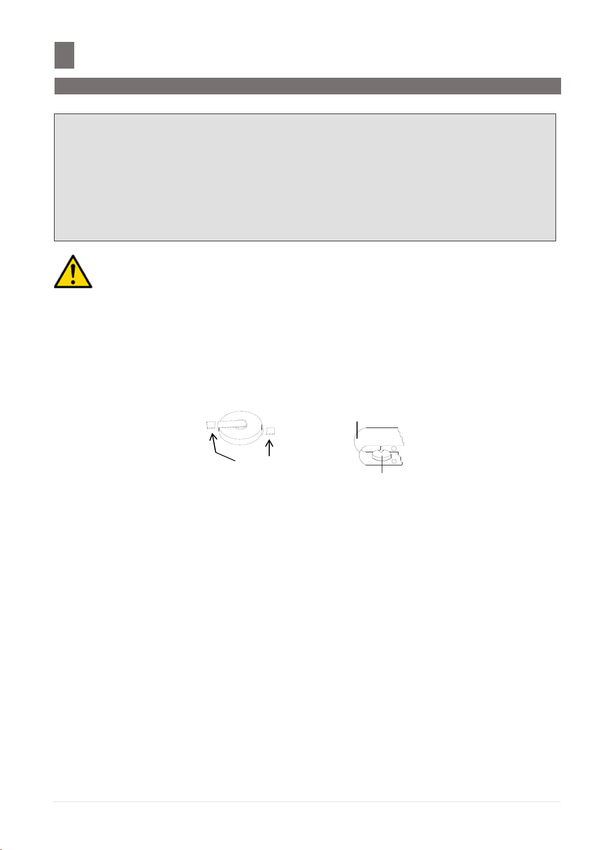
Cut / Break the
Battery Legs
+
-
Tape
Battery
WARNING DISPOSAL:
THE BATTERY MAY BE REGULATED BY NATIONAL OR LOCAL REGULATION. PLEASE
FOLLOW THE INSTRUCTIONS OF PROPER REGULATION. AS ELECTRIC CAPACITY IS LEFT
IN A DISCARDED BATTERY AND IT COMES INTO CONTACT WITH OTHER METALS, IT
COULD LEAD TO DISTORTION, LEAKAGE, OVERHEATING, OR EXPLOSION, SO MAKE SURE
TO CUT/BREAK THE BATTERY LEGS AND COVER THE (+) AND (-) TERMINALS WITH
FRICTION TAPE OR SOME OTHER INSULATOR BEFORE DISPOSAL.
SM- 5 3 0 0 S e r v i c e M a n u a l | 7
Page 8
Cutter Safety Information
–––––––––––––––––––––––––––––––––
Caution For Pinching Hand
ATTENTION RISQUE DE PINCEMENT
Caution For Cutter
ATTENTION AU COUTEAU
Blade Hazard
LAME TRANCHANTE
Cutter Safety Information
1. Please careful the hand when close the printer door.
Note: This label only applies to machine come with Auto Cutter.
2. Please careful the hand when press the cutter release lever.
Note: This label only applies to machine come with Auto Cutter.
3. Please keep hands clear while operating.
SM- 5 3 0 0 S e r v i c e M a n u a l | 8
Page 9

Safety Regulation
––––––––––––––––––––––––––––––––––––––––––––– –––––
Safety Regulations
Federal Communication Commission Interference Statement
This equipment has been tested and found to comply with the limits for a Class B digital device,
pursuant to Part 15 of the FCC Rules. These limits are designed to provide reasonable protection
against harmful interference in a residential installation. This equipment generates uses and can radiate
radio frequency energy and, if not installed and used in accordance with the instructions, may cause
harmful interference to radio communications. However, there is no guarantee that interference will
not occur in a particular installation. If this equipment does cause harmful interference to radio or
television reception, which can be determined by turning the equipment off and on, the user is
encouraged to try to correct the interference by one of the following measures:
- Reorient or relocate the receiving antenna.
- Increase the separation between the equipment and receiver.
- Connect the equipment into an outlet on a circuit different from that to which the receiver is
connected.
- Consult the dealer or an experienced radio/TV technician for help.
This device complies with Part 15 of the FCC Rules. Operation is subject to the following two
conditions: (1) This device may not cause harmful interference, and (2) this device must accept any
interference received, including interference that may cause undesired operation.
FCC Caution: Any changes or modifications not expressly approved by the party responsible for
compliance could void the user's authority to operate this equipment.
IMPORTANT NOTE:
FCC Radiation Exposure Statement:
This equipment complies with FCC RF radiation exposure limits set forth for a portable uncontrolled
environment. To maintain compliance with FCC RF exposure compliance requirements:
1) Please do not attach any decorative components with metal parts to this equipment.
2) The antenna must not be co-located or operating in conjunction with any other antenna or
transmitter.
FCC Radiation Exposure Statement: (Canada)
This equipment complies with FCC RF radiation exposure limits set forth for an uncontrolled
environment. To comply with FCC RF exposure compliance requirements:
1) The antenna used for this transmitter must be installed and operated with minimum 20cm between
the antenna and users.
2) The antenna must not be co-located or operating in conjunction with any other antenna or
transmitter.
SM- 5 3 0 0 S e r v i c e M a n u a l | 9
Page 10

Safety Regulation
––––––––––––––––––––––––––––––––––––––––––––––––––
IDA Compliance Statement: (Singapore)
This equipment registered to comply with IDA (Info-Communications Development Authority of
Singapore) Standard under Dealer's Class License.
IDA Label
SM- 5 3 0 0 S e r v i c e M a n u a l | 10
Page 11

Safety Regulation
––––––––––––––––––––––––––––––––––––––––––––––––––
Items
Y N Identification
Removal procedure
Comments
o Fluids
o Polychlorinated
biphenyls (PCB)
containing capacitors.
o Mercury containing
components, such as
switches or
backlighting lamps.
o Printed circuit boards
of mobile phones.
o Toner cartridges, liquid
and pasty, as well as
color toner.
Treatment And Recovery of WEEE
Component listing of Hazardous Material
To all user of DIGI product in the European Union
Thank you for using DIGI product.
Product marked with this symbol indicates that it was sold on or after 13th August 2005, which means
it should not be disposed of with general household waste. Please note that our product is for
industrial/professional use only.
Treatment and recovery of WEEE involves removing hazardous substances (such as those covered in
the RoHS Directives) as well as PCBs and liquids. Only licensed operators meeting WEEE regulations
will be able to handle and recover WEEE.
Please contact your DIGI office or DIGI distributor when the product has reached the end of its life.
They will advise you regarding the product take-back.
With your co-operation we are aiming to reduce environmental pollution from waste electrical and
electronic equipment and preserve natural resource through re-use and recycling. Please do not
hesitate to ask your DIGI office or DIGI distributor, if you require further information.
Items required to be removed from product at end of product life as listed in WEEE Annex
II
SM- 5 3 0 0 S e r v i c e M a n u a l | 11
Page 12

Treatment And Recovery of WEEE
–––––––––––––––––
Items
Y N Identification
Removal procedure
Comments
o Plastic containing
brominated flameretardants.
o Asbestos waste.
o Cathode ray tubes.
o Chlorofluorocarbons
(CFC), hydro
chlorofluorocarbons
(HCFC)
orhydrofluorocarbons
(HFC), hydrocarbons
(HC).
o Gas discharge lamps.
o Components containing
refractory ceramic
fibred as described in
Commission Directive
97/69/EC of 5
December 1997.
o
o Components containing
radioactive substances.
o
o External electric cables.
o
AC Power Cord.
o Batteries.
1. Lithium Battery.
Refer to
Safety
Information
Warning
Disposal
SM- 5 3 0 0 S e r v i c e M a n u a l | 12
Page 13

Treatment And Recovery of WEEE
–––––––––––––––––
Items
Y N Identification
Removal procedure
Comments
o Other printed circuit
boards greater than 10
square centimeters.
Bench Type:
1. Base Board
- 9.1.3 Disassembly of
Base Board, Keyboard
and Operator Display
LCD – Item 1.
- 9.1.3 Disassembly of
Base Board, Keyboard
and Operator Display
LCD.
(Step 1 ~ 2)
2. Keyboard
- 9.1.3 Disassembly of
Base Board, Keyboard
and Operator Display
LCD – Item 2.
- 9.1.3 Disassembly of
Base Board, Keyboard
and Operator Display
LCD.
(Step 1 ~ 4)
3. Power Unit
- 9.1.4 Disassembly of
Power Unit – Item 3.
- 9.1.1 Disassembly of
Platter Support and Top
Cover.
(Step 1 ~ 4)
- 9.1.4 Disassembly of
Power Unit.
4. AD Board
- 9.1.5 Disassembly of
AD Board – Item 4.
- 9.1.1 Disassembly of
Platter Support and Top
Cover.
(Step 1 ~ 4)
- 9.1.5 Disassembly of
AD Board.
(Step 1 ~ 2)
SM- 5 3 0 0 S e r v i c e M a n u a l | 13
Page 14

Treatment And Recovery of WEEE
–––––––––––––––––
Items
Y N Identification
Removal procedure
Comments
Pole Type:
1. Base Board
- 9.2.3 Disassembly of
Base Board, Keyboard
and Operator Display
LCD – Item 1.
- 9.2.3 Disassembly of
Base Board, Keyboard
and Operator Display
LCD.
(Step 1 ~ 2)
2. Keyboard
- 9.2.3 Disassembly of
Base Board, Keyboard
and Operator Display
LCD – Item 2.
- 9.2.3 Disassembly of
Base Board, Keyboard
and Operator Display
LCD.
(Step 1 ~ 4)
3. Power Unit
- 9.2.4 Disassembly of
Power Unit – Item 3.
- 9.2.2 Disassembly of
Top Cover.
(Step 1 ~ 2)
- 9.2.4 Disassembly of
Power Unit.
4. AD Board
- 9.2.5 Disassembly of
AD Board – Item 4.
- 9.2.2 Disassembly of
Top Cover.
(Step 1 ~ 2)
- 9.2.5 Disassembly of
AD Board – Item 4.
(Step 1 ~ 2)
5. IO Board
- 9.2.1 Disassembly of
Pole, Customer Display
Board & LCD – Item 5.
- 9.2.1 Disassembly of
Pole, Customer Display
Board & LCD.
(Step 1 ~ 2)
SM- 5 3 0 0 S e r v i c e M a n u a l | 14
Page 15

Treatment And Recovery of WEEE
–––––––––––––––––
Items
Y N Identification
Removal procedure
Comments
o Liquid crystal displays
(together with their
casing where
appropriate) of a
surface greater than
100 cm2 and all those
back-lighted with gas
discharge lamps.
Bench Type:
1. Operator Display LCD
- 9.1.3 Disassembly of
Base Board, Keyboard
and Operator Display
LCD – Item 5.
- 9.1.3 Disassembly of
Base Board, Keyboard
and Operator Display
LCD.
2. Customer Display LCD
- 9.1.2 Disassembly of
Customer Display LCD
– Item 6.
- 9.1.1 Disassembly of
Platter Support and Top
Cover.
(Step 1 ~ 2)
- 9.1.2 Disassembly of
Customer Display LCD.
(Step 2)
Pole Type:
1. Operator Display LCD
- 9.2.3 Disassembly of
Base Board, Keyboard
and Operator Display
LCD – Item 5.
- 9.2.3 Disassembly of
Base Board, Keyboard
and Operator Display
LCD.
(Step 1 ~ 4)
2. Customer Display LCD
- 9.2.1 Disassembly of
Pole, Customer Display
Board & LCD – Item 6.
- 9.2.2 Disassembly of
Pole, Customer Display
Board & LCD.
(Step 1)
SM- 5 3 0 0 S e r v i c e M a n u a l | 15
Page 16

Product Information
––––––––––––––––––––––––––––––––––––––––––––––
1.1 Model Specification
Variation
:
Description:
Model:
Dimension (D x W x H in mm):
Bench
-
SM-5300B
-
472 (adjustable) x 360 x 136
Pole
-
SM-5300P
-
500 (adjustable) x 360 x 542
Elevated
-
SM-5300EV
-
438 x 360 x 550
Self Service Pole
-
SM-5300SSP
-
480 x 442 x 757
CPU
:
iMX6Solo Single Core Arm Cortex® A9™ 1GHz
SD Card
:
8GB Class 10 SDHC Card
RAM
:
On board 512MB DDR3
Operating
System
:
LINUX
Loadcell
:
NMB type
(For all countries except USA & Canada)
K-type
(For USA & Canada only)
Capacity
:
6kg (3kg and less, e = 1g / more than 3kg, e = 2g)
15kg (6kg and less, e= 2g / more than 6kg, e = 5g)
30kg (15kg and less, e = 5g / more than 15kg, e = 10g)
30lb (15lb and less, e = 0.005lb / more than 30lb, e = 0.01lb)
Keyboard
:
23 x Alphanumeric Function Keys
28 x Preset Keys
Display
Resolution
:
1/3000, 1/6000 or 1/7500 (Single-interval)
Operator
Display
:
B / P / EV
-
7” (800 x 480) TFT WVGA LCD with LED Backlight, Touch Panel
SSP
-
19” (1280 x 1024) TFT SXGA LCD with LED Backlight, Touch
Panel
Customer
Display
:
B / P / EV
-
7” (800 x 480) TFT WVGA LCD with LED Backlight
SSP
-
Nil
Weight
:
SM-5300B
-
11.5kg
SM-5300P
-
11.8kg
SM-5300EV
-
12.5kg
SM-5300SSP
-
19.0kg
Production Information
1.1 Model Specification
SM- 5 3 0 0 S e r v i c e M a n u a l | 16
Page 17

Product Information
––––––––––––––––––––––––––––––––––––––––––––––
1.1 Model Specification
Printing
: Print Media
-
Label / Receipt paper
Paper Width
-
60mm (max.)
Print Speed
-
120mm/s
* Subject to the sensitivity of print media
Print Width
-
56mm
Print Length
-
350mm (max.)
Max Roll Diameter
-
105mm
Resolution
-
200dpi
I/O
Interface
:
1 x Ethernet 10/100 Base T
4 x USB (2.0)
Optional
Interface
:
AP-3001G (USB)
BS-03 (USB)
SM- 5 3 0 0 S e r v i c e M a n u a l | 17
Page 18

Product Information
––––––––––––––––––––––––––––––––––––––––––––––
1.2 Operating Specification
Power Source
:
AC Supply 100 ~ 240V (Auto-switching)
Power
Consumption
:
AC Supply 100 ~ 120V_(nominal: 14W, 0.25A) / (max: 55W, 1.0A)
AC Supply 220 ~ 240V_(nominal: 14W, 0.16A) / (max: 55W, 0.55A)
Frequency
:
50 / 60Hz
Operating
Temperature
:
-10 °C to +40 °C
Operating
Humidity
:
15% to 85%RH
1.2 Operating Specification
*Specifications are subject to change without notice
SM- 5 3 0 0 S e r v i c e M a n u a l | 18
Page 19

Product Information
––––––––––––––––––––––––––––––––––––––––––––––
1.3 Overall Diamension (in mm)
1.3 Overall Dimension (in mm)
1.3.1 Bench (B)
SM- 5 3 0 0 S e r v i c e M a n u a l | 19
Page 20

Product Information
––––––––––––––––––––––––––––––––––––––––––––––
1.3 Overall Diamension (in mm)
1.3.2 Pole (P)
SM- 5 3 0 0 S e r v i c e M a n u a l | 20
Page 21

Product Information
––––––––––––––––––––––––––––––––––––––––––––––
1.3 Overall Diamension (in mm)
1.3.3 Elevated (EV)
SM- 5 3 0 0 S e r v i c e M a n u a l | 21
Page 22

Product Information
––––––––––––––––––––––––––––––––––––––––––––––
1.3 Overall Diamension (in mm)
1.3.4 Self Service Pole (SSP)
SM- 5 3 0 0 S e r v i c e M a n u a l | 22
Page 23

Product Information
––––––––––––––––––––––––––––––––––––––––––––––
1.4 Label & Receipt Specifications
Outer diameter of rolls:
Maximum 105mm
Inner diameter of rolls:
Minimum 40mm
Wide of label/linerless label:
60mm
LABEL TYPE
LABEL SIZE
PCS/ROLL
T1
60 x 28
1400
T2
60 x 31
1300
T3
60 x 34
1200
T4/T10
60 x 40
1000
T5/T11
60 x 43
960
T6
60 x 46
900
T7/T12
60 x 49
840
T8
60 x 55
750
T9
60 x 37
1100
S
40 x 28
1400
A / B
40 x 46
900
C
40 x 62
670
F1 – F99 (Free format)
60 (max) x 350 (max)
-
REMARKS:
i) LABEL SIZE is in Width X Length and in millimeter unit.
ii) F1 to F99 is self-design free format label. Please note the minimum and maximum size.
WIDE OF LABEL / LINERLESS LABEL
1.4 Label & Receipt Specifications
SM- 5 3 0 0 S e r v i c e M a n u a l | 23
Page 24

Keysheet And Display
–––––––––––––––––––––––––––––––––––––––––––
2.1 Key Sheet Layout And Key Function
Key Button
Key Function
Description
ON/ OFF Key
Turn on/off the display.
to
0-9 key
Enter numeric data.
REZERO Key
Reset weight to "0".
TARE Key
Set or Clear the tare value.
CLEAR Key
Clear entered data.
Key Sheet And Display
2.1 Key Sheet Layout And Key Function
2.1.1 Key Sheet Layout
*Actual legends and symbols may differ depending on local regulations and requirements.
2.1.2 Key Function
Refer to the followings for detail explanation for each key on the key panel.
SM- 5 3 0 0 S e r v i c e M a n u a l | 24
Page 25

Keysheet And Display
–––––––––––––––––––––––––––––––––––––––––––
2.1 Key Sheet Layout And Key Function
PLU Key
Calling up PLU in Registration mode.
Used as ENTER key in programming mode.
MULTIPLY Key
Multiply the number for non-weighing product.
Used as ESCAPE key in programming mode.
PRINT Key
Printing label or receipt in Registration mode.
FEED Key
Feed label or receipt.
SM- 5 3 0 0 S e r v i c e M a n u a l | 25
Page 26
Keysheet And Display
–––––––––––––––––––––––––––––––––––––––––––
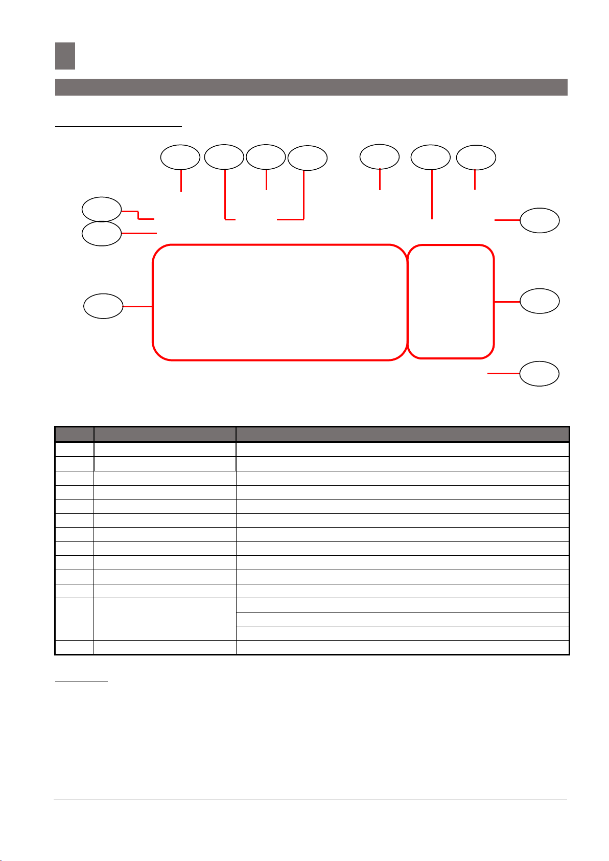
2.2 Operator And Customer Display Indicator Layout
No.
Area /Function
USAGE
1
Tare Display
Display Tare Value
2
Weight Display
Display Weight value
3
Unit Price Display
Display Unit Price
4
Total Price Display
Display Total Price
5
Zero Indicator
Display when Scale is stable at the zero point
6
Net Indicator
Display when Tare Subtraction is being performed
7
Mode Status Indicator
Indicate the current status (Manual Mode or Prepack Mode)
8
Commodity Name
Shows the Commodity Name of the called up PLU
9
Preset keys
Used for calling up PLUs / Function keys
10
Next Page keys
Turn to next page of Preset / Function keys
11
Function keys
Used for calling up Clerk / Function keys
12
Scale Indicator
Shows S when Scale is configure SERVER
Shows C when Scale is configure CLIENT
Shows L when Client is OFF LINE
13
Date & Time
Show the current Date and Time
13 4 3
10
11
12 5 2 6 7
1 9 8
2.2 Operator And Customer Display Indicator Layout
2.2.1 Operator Display
REMARKS:
1) PREV & NEXT keys will appears when there is more than 1 page of Preset/Function keys.
2) When in Prepack Mode, the Function keys at the bottom if the screen will not be shown.
3) Re-phrase image in Reg. Preset keys, need to select in Programming of Preset Keys.
SM- 5 3 0 0 S e r v i c e M a n u a l | 26
Page 27

Keysheet And Display
–––––––––––––––––––––––––––––––––––––––––––
2.2 Operator And Customer Display Indicator Layout
No.
Area /Function
Usage
1
Tare Display
Display Tare Value
2
Zero Indicator
Display when Scale is stable at the zero point/value
3
Weight Indicator
Display Weight or Net Weight Indicator
i) Display as “Net Weight” when Tare Subtraction is being performed
ii) Display as “Weight” when no tare performed
4
Weight Display
Display Weight value
5
Unit Price Display
Display Unit Price amount
6
Total Price Display
Display Total Price amount
7
Data/Instruction Display
Display data, operation, instruction, keypad and etc
1 2 3 4 5 6 7
2.2.2 Self Service Display
SM- 5 3 0 0 S e r v i c e M a n u a l | 27
Page 28

Software Functional Structure
––––––––––––––––––––––––
MENU
Registration
Weighing Mode
Maintenance
Maintenance
Service Advance Daily Scheduler Serial Port Config Date & Time Informat Server
Scale
PLU Preset Key Barcode PLU Related Traceability CCD EL Display
Programming
Product Info Customer Print Format Scroll Info Setup Advanced Setup E-Label
Maintenance Module Spec System Info USB Image Transfer User Spec SQL Log Restore
Data Transmission Viewer Scale Spec @ Label Cloud Config Info Collect USB Backup Restore
Registration Programming Maintenance Report Closing Report
Web Browser Self Service Kiosk Queue Training Mode
Scale Printer Database Hardware Test Scale IP Network Test
Plug ‘N’ Weigh Setting Queue System Camera Maintenance Display Setting
W&M Spec Calibration IR Count Audit Trial Write Checksum Scale Level
Software Functional Structure
SM- 5 3 0 0 S e r v i c e M a n u a l | 28
Page 29

Software Functional Structure
––––––––––––––––––––––––
Printer
Printer Spec Printer Test Printer Server Config External Printer IP
Printer Spec
Printer 1 Printer 2
Printer Test
Status Sensor Firmware Thermal Head Cutter
Hardware Test
Input USB Ethernet Cash Drawer LCD RS232
Database
INIT Restore Database Migration Server IP
Date and Time
Date Time
Service Advance
Backup Load Default Data Clear Open Transaction Transaction
USB Backup
Restore
VNC
RF Bridge
E-Label
Hardware
Auto Test
Printer Test
W&M User
Maintenance
Time Zone
NTP/DST
TrueType
Font Config
Kiosk Order
Test
Informat MAC
Address
MAC Address
Config Firewall
Default Data
TWS TCP Test
Wireless Setting
Replication Verifier
Touch Screen
Calibration
SM- 5 3 0 0 S e r v i c e M a n u a l | 29
Page 30

Software Functional Structure
––––––––––––––––––––––––
Serial Port
/dev/tty/S0 /dev/tty/S1 /dev/ttyTWSBS /dev/ttyTWSBS2
Network Test
Manual Servers
Daily Schedule
Hour Minute
User Spec
Barcode CCTV Communication Label Receipt Settings
Module Spec
Scale Spec
Scale Price Scale Tare Scale Operation Scale Tax
System Info
Scale Sub CPU Database Boot Flash System SD Card Bank Terminal
Password CCD Others Colli Traceability Price List
Web Browser Language Proximity Card Auto Cutter
TWSWTCP Communication Queue System E-Label, Hi-Touch & InfoCard
Note: To activate the highlighted functional in above, required to enable the spec.
SM- 5 3 0 0 S e r v i c e M a n u a l | 30
Page 31

I/O Port, Span Switch and W&M Sealing
––
4.1 I/O Port
SD Card Protective Bracket
Bottom View
Latch
Side View
SD Card insert direction
Ethernet Port
USB Port (x4)
Cash Drawer
SD Slot
I/O Ports, Span Switch And W&M Sealing
4.1 I/O Ports
4.1.1 Bench (B) / Pole (P)
SM- 5 3 0 0 S e r v i c e M a n u a l | 31
Page 32

I/O Port, Span Switch and W&M Sealing
––
4.1 I/O Port
Unscrew the 2pcs Yuriya screw to
remove the bottom cover.
SD Card Insert Direction
Unscrew the M3x8 binding head
screw to open the SD Card cover.
Rear View from Operator Display
Cash Drawer USBx4 Ethernet
4.1.2 Elevated (EV)
SM- 5 3 0 0 S e r v i c e M a n u a l | 32
Page 33

I/O Port, Span Switch and W&M Sealing
––
4.1 I/O Port
Unscrew the 2pc Yuriya screw
to remove the bottom cover.
Location of SD Card
Unscrew the M3x8 Sems
B screw to open the SD
Card cover.
Rear View from Operator Display
SD Card Insert Direction
Cash Drawer USBx4 Ethernet
4.1.3 Self Service Pole (SSP)
SM- 5 3 0 0 S e r v i c e M a n u a l | 33
Page 34

I/O Port, Span Switch And W&M Sealing
––
4.2 Span Switch
Enable
Disable
Unscrew 2 pcs Sealing screw
to remove the bracket.
4.2 Span Switch
SM- 5 3 0 0 S e r v i c e M a n u a l | 34
Page 35

I/O Port, Span Switch And W&M Sealing
––
4.3 W&M Sealing
Bottom View
Sealing Screw
Sealing Thread
Sealing Sticker
Sealing Cover
Note: We can use Sealing Screw & Thread or Sticker on the Sealing cover
SM-5300 Model Variant & Sealing Position
4.3 W&M Sealing
SM- 5 3 0 0 S e r v i c e M a n u a l | 35
Page 36

Initial Setup
––––––––––––––––––––––––––––––––––––––––––––––––––––––––––––––––
5.1 Lever Adjustment
Place the scale on the flat surface and adjust the
four legs until the bubble on the lever is in the
Bubble
Initial Setup
5.1 Level Adjustment
SM- 5 3 0 0 S e r v i c e M a n u a l | 36
Page 37

Initial Setup
––––––––––––––––––––––––––––––––––––––––––––––––––––––––––––––––
5.2 Cassette Belt Tension and Label Guide Adjustment
Loosen the screw and
adjust the bracket for
Belt Tension becomes
the Tight (Up) or Loose
(Down).
Loosen the Yuriya screw
and adjust the Cassette
Label Guide position.
Yuriya
screw
5.2 Cassette Belt Tension and Label Guide Adjustment
5.3 Cassette Label Guide Adjustment
SM- 5 3 0 0 S e r v i c e M a n u a l | 37
Page 38

Initial Setup
––––––––––––––––––––––––––––––––––––––––––––––––––––––––––––––––
5.3 Cassette Loading and Printing Option
Label Printing
Receipt Printing
Unblock
Block
(cover by white paper)
5.3 Cassette Loading and Printing Option
If printer spec setting [143A016 Printer 1 Label/Receipt Control] is set to [0: By Sensor], the
table in below shows the holes setting for the cassette.
*Note: For Printer firmware version V12.80 and above.
SM- 5 3 0 0 S e r v i c e M a n u a l | 38
Page 39

Initial Setup
––––––––––––––––––––––––––––––––––––––––––––––––––––––––––––––––
5.4 Sensor Location
Print Media Sensor:
Depend on Cassette 3 hole covered to change the
LABEL or RECEIPT printing method.
Label Gap Sensor:
When Gap Label Cassette to used.
Note: There are two position to set depend on
Label type.
Peel Sensor:
When Gap Label Cassette to used.
5.4 Sensor Location
5.4.1 Peel Sensor
5.4.2 Gap & Paper End Sensor
5.4.3 Print Media Sensor
SM- 5 3 0 0 S e r v i c e M a n u a l | 39
Page 40

Initial Setup
––––––––––––––––––––––––––––––––––––––––––––––––––––––––––––––––
5.4 Sensor Location
If the Printer door not properly to closed, this switch
will open and the printing function will not working.
If Cassette loading not properly, the switch will open
and the printing function will not working.
5.4.4 Cassette Detection Sensor
5.4.5 Printer Door Open/Close Sensor
SM- 5 3 0 0 S e r v i c e M a n u a l | 40
Page 41

Initial Setup
––––––––––––––––––––––––––––––––––––––––––––––––––––––––––––––––
5.5 Software Setup
Procedure
Picture
1) In Registration mode, press and follow by
key button to MENU [MAINTENANCE]
[MAINTENANCE] [SERVICE ADVANCE] to go to
Service Advance mode.
2) Keying the Password and select [ENTER] button.
Password: 0953
3) Select [DEFAULT DATA].
4) In DEFAULT SPEC mode, select [LOAD FACTORY
DEFAULT].
5.5 Software Setup
5.5.1 Default Country SPEC
Note: Ensure the Span Switch is set to [Enable].
SM- 5 3 0 0 S e r v i c e M a n u a l | 41
Page 42

Initial Setup
––––––––––––––––––––––––––––––––––––––––––––––––––––––––––––––––
5.5 Software Setup
Procedure
Picture
5) If message appear as shown, select [MENU] to go
back to DEFAULT SPEC mode. Turn ON Span Switch
and proceed to Step 2 again.
6) Touch icon to select the country. And then click
[CONTINUE].
SM- 5 3 0 0 S e r v i c e M a n u a l | 42
Page 43

Initial Setup
––––––––––––––––––––––––––––––––––––––––––––––––––––––––––––––––
5.5 Software Setup
Procedure
Picture
1) In Registration mode, press and follow by
key button to MENU [MAINTENANCE] [USER
SPEC].
2) In USER SPEC mode, select the desired SPEC
option, e.g. [BARCODE].
Note:
Refer to Section 5.5.5.1 on SEARCH function
procedures
3) Select the desired SPEC option, e.g. [ITEM
BARCODE].
4) Touch the column and enter new setting or touch
the icon to select the new setting.
5.5.2 User SPEC
SM- 5 3 0 0 S e r v i c e M a n u a l | 43
Page 44

Initial Setup
––––––––––––––––––––––––––––––––––––––––––––––––––––––––––––––––
5.5 Software Setup
Procedure
Picture
5) Select [SAVE] button to save the changed setting.
Procedure
Picture
1) In Registration mode, press and follow by
key button to MENU [MAINTENANCE]
[MODULE SPEC].
2) Enter the Password and press [PLU] key button.
Password: 6289
3) In MODULE SPEC mode, select the desired SPEC
option, e.g. [e.LABEL, HI-TOUCH & INFO-CARD].
Note:
Refer to Section 5.5.5.1 on SEARCH function
procedures:
5.5.3 Module SPEC
SM- 5 3 0 0 S e r v i c e M a n u a l | 44
Page 45

Initial Setup
––––––––––––––––––––––––––––––––––––––––––––––––––––––––––––––––
5.5 Software Setup
Procedure
Picture
4) Touch the column and enter new setting or touch
the icon to select the new setting.
5) Select [SAVE] button to save the changed setting.
Procedure
Picture
1) In Registration mode, press and follow by
key button to MENU [MAINTENANCE] [SCALE
SPEC].
2) Enter the Password and press key button.
Password: 3846
5.5.4 Scale SPEC
SM- 5 3 0 0 S e r v i c e M a n u a l | 45
Page 46

Initial Setup
––––––––––––––––––––––––––––––––––––––––––––––––––––––––––––––––
5.5 Software Setup
Procedure
Picture
3) In SCALE SPEC mode, select the desired SPEC
option, e.g. [SCALE PRICE].
Note:
Refer to Section 5.5.5.1 on SEARCH function
procedures:
4) Touch the column and enter new setting or touch
the icon to select the new setting.
5) Select [SAVE] button to save the changed setting.
SM- 5 3 0 0 S e r v i c e M a n u a l | 46
Page 47

Initial Setup
––––––––––––––––––––––––––––––––––––––––––––––––––––––––––––––––
5.5 Software Setup
Procedure
Picture
1) In Registration mode, press and follow by
key button to MENU [MAINTENANCE]
[MAINTENANCE] [SCALE] [W&M SPEC] to
go to W&M (Weight & Measure) SPEC mode.
2) Turn on the Span Switch and press key
button.
3) In W&M SPEC mode, select desired SPEC option,
e.g. [W&M SCALE].
Note:
Refer to Section 5.5.5.1 on SEARCH function
procedures
4) Touch icon to select the new setting.
5.5.5 Weight & Measure SPEC
SM- 5 3 0 0 S e r v i c e M a n u a l | 47
Page 48

Initial Setup
––––––––––––––––––––––––––––––––––––––––––––––––––––––––––––––––
5.5 Software Setup
Procedure
Picture
5) Select [SAVE] button to save the changed setting.
Procedure
Picture
1) Touch [SEARCH] button.
2) Touch the “Search By” column area.
3) Keyboard screen will pop out. Enter the SPEC no.
or key word follow by [ENTER] button.
5.5.5.1 SEARCH Function Procedure:
SM- 5 3 0 0 S e r v i c e M a n u a l | 48
Page 49

Initial Setup
––––––––––––––––––––––––––––––––––––––––––––––––––––––––––––––––
5.5 Software Setup
Procedure
Picture
4) Message will display on screen indicating the search
results as shown.
5) All related SPEC would display on the screen.
Spec found
Spec not found
SM- 5 3 0 0 S e r v i c e M a n u a l | 49
Page 50

Initial Setup
––––––––––––––––––––––––––––––––––––––––––––––––––––––––––––––––
5.5 Software Setup
Procedure
Picture
1) In Registration mode, press and follow by
key button to MENU [MAINTENANCE]
[MAINTENANCE] [DATE AND TIME] to go to
Date And Time menu.
2) At Date mode, use arrow key to select the
“Year” and select the date.
3) Select [SAVE] button to save the changed setting.
4) Select [TIME] to go to Time mode, then press
“Number” button to enter the time.
5.5.6 Date and Time
SM- 5 3 0 0 S e r v i c e M a n u a l | 50
Page 51

Initial Setup
––––––––––––––––––––––––––––––––––––––––––––––––––––––––––––––––
5.5 Software Setup
Procedure
Picture
5) Select [SAVE] button to save the change setting.
SM- 5 3 0 0 S e r v i c e M a n u a l | 51
Page 52

Initial Setup
––––––––––––––––––––––––––––––––––––––––––––––––––––––––––––––––
5.5 Software Setup
Procedure
Picture
1) In Registration mode, press and follow by
key button to MENU [MAINTENANCE]
[MAINTENANCE] [SERVICE ADVANCE] to go
to Service Advance mode.
2) Keying the Password and select [ENTER] button.
Password: 0953
3) In Service Advance mode, select [TIME ZONE /
NTP / DST CONFIG].
4) Set the setting and touch [SAVE] button to save
the setting changed.
5.5.7 Daylight Saving Time
SM- 5 3 0 0 S e r v i c e M a n u a l | 52
Page 53

Initial Setup
––––––––––––––––––––––––––––––––––––––––––––––––––––––––––––––––
5.6 Span Adjustment (Weight Calibration)
Procedure
Picture
1) In Registration mode, press and follow by
key button to MENU [MAINTENANCE]
[MAINTENANCE] [SCALE] [CALIBRATION]
to go to calibration mode.
2) In Calibration mode, check the setting and touch
[NEXT] to continue.
3) Ensure there is no weight on the platter, and touch
[NEXT].
4) Wait for Zero Weight calibration in progress.
5.6 Span Adjustment (Weight Calibration)
Note: Ensure the Span Switch is set to [Enable].
SM- 5 3 0 0 S e r v i c e M a n u a l | 53
Page 54

Initial Setup
––––––––––––––––––––––––––––––––––––––––––––––––––––––––––––––––
5.6 Span Adjustment (Weight Calibration)
Procedure
Picture
5) Put capacity weight [e.g. 15Kg] on the platter and
touch [NEXT].
6) Waiting for Full Weight calibration in progress.
7) Screen shows “CALIBRATION COMPLETE”
indicating the process is completed.
SM- 5 3 0 0 S e r v i c e M a n u a l | 54
Page 55

Initial Setup
––––––––––––––––––––––––––––––––––––––––––––––––––––––––––––––––
5.7 From Service Screen Exit to Main Menu Screen
Procedure
Picture
1) In the Registration Mode screen, touch the
Top/Bottom display corner area point follow by
Note: Ensure the Weight is zero modes.
2) Keying the Password [1234] (default) and touch
[Enter] button.
Note: If touch the [Back] button, the display will go
back to Registration Mode screen.
3) Touch [Quit] button to enter Self-Service Main
Menu.
4) This is SM-5300SSP Self-Service Pole Main Menu. If
want return to Self Service Registration Mode screen
touch [Self Service] button.
1
2 3 4
2 3 4
1
5.7 From Self Service Screen Exit to Main Menu Screen
SM- 5 3 0 0 S e r v i c e M a n u a l | 55
Page 56

System Setup
–––––––––––––––––––––––––––––––––––––––––––––––––––––––––––––
6.1 Network Setup
Procedure
Picture
1) In Registration mode, press and follow by
key button to MENU [MAINTENANCE]
[MAINTENANCE] [SCALE IP] to go to SCALE IP
mode.
2) Enter setting (Interface, Address, Net Mask,
Gateway, DNS) and touch [SAVE] button.
3) Select [YES] button to save the changed setting.
Note:
If select [NO] button will return to SCALE IP mode.
System Setup
6.1 Network Setup
6.1.1 Network Configuration
SM- 5 3 0 0 S e r v i c e M a n u a l | 56
Page 57

System Setup
–––––––––––––––––––––––––––––––––––––––––––––––––––––––––––––
6.1 Network Setup
Procedure
Picture
1) In Registration mode, press and follow by
key button go to MENU [MAINTENANCE]
[MAINTENANCE] [SERVICE ADVANCE] to go
to Service Advance maintenance mode.
2) Keying the Password and select [ENTER] button.
Password: 0953
3) In Service Advance mode, touch [MAC
ADDRESS].
4) Editing the MAC Address and then press (Print)
key or select [SET] button to save the changed
setting.
6.1.2 Scale MAC Address
SM- 5 3 0 0 S e r v i c e M a n u a l | 57
Page 58

System Setup
–––––––––––––––––––––––––––––––––––––––––––––––––––––––––––––
6.1 Network Setup
Procedure
Picture
1) In Registration mode, press and follow by
key button go to MENU [MAINTENANCE]
[MAINTENANCE] [SERVICE ADVANCE] to go to
Service Advance maintenance mode.
2) Keying the Password and select [ENTER] button.
Password: 0953
3) In Service Advance mode, touch [VNC
PASSWORD].
4) Touch the column of “Enter New Password”.
6.1.3 VNC Password
SM- 5 3 0 0 S e r v i c e M a n u a l | 58
Page 59

System Setup
–––––––––––––––––––––––––––––––––––––––––––––––––––––––––––––
6.1 Network Setup
Procedure
Picture
5) Keying the Password (max. 8 number/character)
6) Touch the column of “Confirm New Password”.
7) Keying the same Password for confirmation.
8) Touch [SAVE] to save the setting.
SM- 5 3 0 0 S e r v i c e M a n u a l | 59
Page 60

System Setup
–––––––––––––––––––––––––––––––––––––––––––––––––––––––––––––
6.1 Network Setup
Procedure
Picture
9) Touch [YES] to reboot the scale.
SM- 5 3 0 0 S e r v i c e M a n u a l | 60
Page 61

System Setup
–––––––––––––––––––––––––––––––––––––––––––––––––––––––––––––
6.2 Wireless Adapter Setting
Procedure
Picture
1) In Registration mode, press and follow by
key button go to MENU [MAINTENANCE]
[MAINTENANCE] [SERVICE ADVANCE] to go to
Service Advance maintenance mode.
2) Keying the Password and select [ENTER] button.
Password: 0953
3) In Service Advance mode, touch [WIRELESS
SETTING].
4) Touch the column of “ESSID”.
6.2 Wireless Adapter Setting
6.2.1 WLAN AP-3001G Setup
SM- 5 3 0 0 S e r v i c e M a n u a l | 61
Page 62

System Setup
–––––––––––––––––––––––––––––––––––––––––––––––––––––––––––––
6.2 Wireless Adapter Setting
Procedure
Picture
5) Keying the ESSID.
(E.g. SM-5300).
Then touch
[ENTER].
6) Select the column of “SECURITY MODE”.
7) Select desired security mode
(E.g. WPA2PSK),
then
touch [SAVE] to save change setting.
8) Select the column of “KEY”.
SM- 5 3 0 0 S e r v i c e M a n u a l | 62
Page 63

System Setup
–––––––––––––––––––––––––––––––––––––––––––––––––––––––––––––
6.2 Wireless Adapter Setting
Procedure
Picture
9) Keying the Password.
(E.g. 1234567890).
Then
touch [ENTER].
10) Touch [SAVE] button to save setting changed.
11) Setting Successfully changed.
SM- 5 3 0 0 S e r v i c e M a n u a l | 63
Page 64

Hardware Test And Maintenance
–––––––––––––––––––
7.1 Internal Count
Procedure
Picture
1) In Registration mode, press and follow by
key button to MENU [MAINTENANCE]
[MAINTENANCE] [SCALE] [IR COUNT] to
go to Internal Count mode.
2) Internal Count mode.
No Weight
Full Weight
Hardware Test And Maintenance
7.1 Internal Count Mode
SM- 5 3 0 0 S e r v i c e M a n u a l | 64
Page 65

Hardware Test And Maintenance
–––––––––––––––––––
7.2 Printer Test
Procedure
Picture
1) In Registration mode, press and follow by
key button to MENU [MAINTENANCE]
[MAINTENANCE] [PRINTER] [PRINTER
TEST] to go to printer test mode.
2) In Printer Test menu, select [STATUS] will show
the status of Printer.
3) Open the scale front door; the [Head Open]
check box will appear tick mark that means the Head
Open Switch is working.
4) Pull out the Cassette a little bit; the [Cassette
Open] check box will appear tick mark that means
the Head Open sensor is working.
7.2 Printer Test
7.2.1 Sensors Status
SM- 5 3 0 0 S e r v i c e M a n u a l | 65
Page 66

Hardware Test And Maintenance
–––––––––––––––––––
7.2 Printer Test
Procedure
Picture
5) Take a label paper and place in front of the peel
sensor, and then check the [Peel Sensor] check box
will appear tick mark, that means the peel sensor is
working.
6) Remove the cassette and the hole [2] is covered,
then put back the cassette to the scale, and check the
[Receipt] check box will appear tick mark.
SM- 5 3 0 0 S e r v i c e M a n u a l | 66
Page 67

Hardware Test And Maintenance
–––––––––––––––––––
7.2 Printer Test
Procedure
Picture
1) In Registration mode, press and follow by
key button to MENU [MAINTENANCE]
[MAINTENANCE] [PRINTER] [PRINTER
TEST] to go to printer test mode.
2) In Printer Test menu, select [SENSOR].
3) Under “Gap” column, touch [Deep Calibration]
to calibrate the gap sensor. A reading of Minimum,
Maximum and Threshold will appear.
Note:
Threshold value is total of min. + max. divided by 2.
4) Touch [Lite Calibration] to calibrate the gap
sensor. A reading of Minimum, Maximum and
Threshold will appear.
Note:
Threshold value is total of min. + max. divided by 2.
7.2.2 Sensor Calibration
7.2.2.1 Gap Sensor Calibration
SM- 5 3 0 0 S e r v i c e M a n u a l | 67
Page 68

Hardware Test And Maintenance
–––––––––––––––––––
7.2 Printer Test
Procedure
Picture
1) In Registration mode, press and follow by
key button to MENU [MAINTENANCE]
[MAINTENANCE] [PRINTER] [PRINTER
TEST] to go to printer test mode.
2) In Printer Test menu, select [SENSOR].
3) Under “Peel” column, Touch [Calibration] to
calibrate the Peel Sensor. A reading of Minimum,
Maximum and Threshold will appear.
7.2.2.2 Peel Sensor Calibration
SM- 5 3 0 0 S e r v i c e M a n u a l | 68
Page 69

Hardware Test And Maintenance
–––––––––––––––––––
7.2 Printer Test
Procedure
Picture
1) In Registration mode, press and follow by
key button to MENU [MAINTENANCE]
[MAINTENANCE] [PRINTER] [PRINTER
TEST] to go to printer test mode.
2) In Printer Test menu, select [SENSOR].
3) Under “Paper End” column, Touch [Calibration]
to calibrate the Paper End Sensor.
4) Remove the label from cassette (without any label
or receipt paper) and put back to scale. Then select
[YES].
7.2.2.3 Paper End Sensor Calibration
SM- 5 3 0 0 S e r v i c e M a n u a l | 69
Page 70

Hardware Test And Maintenance
–––––––––––––––––––
7.2 Printer Test
Procedure
Picture
5) A reading of Minimum, Maximum and Threshold will
appear. Then touch [Calibration] button again.
6) Put back the label to cassette. The Threshold value
should be lower than without label/receipt paper
value
. (E.g. 267 lower than 993)
SM- 5 3 0 0 S e r v i c e M a n u a l | 70
Page 71

Hardware Test And Maintenance
–––––––––––––––––––
7.2 Printer Test
Procedure
Picture
1) In Registration mode, press and follow by
key button go to MENU [MAINTENANCE]
[MAINTENANCE] [PRINTER] [PRINTER
TEST] to go to printer test mode.
2) In Printer Test menu, select [THERMAL] and
touch [DETECT] to read the Printer Thermal head
type.
7.2.3 Thermal Head Type Detection
SM- 5 3 0 0 S e r v i c e M a n u a l | 71
Page 72

Hardware Test And Maintenance
–––––––––––––––––––
7.3 Database Maintenance
Procedure
Picture
1) In Registration mode, press and follow by
key button go to MENU [MAINTENANCE]
[MAINTENANCE] [DATABASE] to go to
DATABASE mode.
2) In Database menu, select [INIT].
3) Select the desired any or all database, then touch
[START] button to start initialization.
4) Select [YES] to confirm initialization database.
7.3 Database Maintenance
7.3.1 Database Initialization
SM- 5 3 0 0 S e r v i c e M a n u a l | 72
Page 73

Hardware Test And Maintenance
–––––––––––––––––––
7.3 Database Maintenance
Procedure
Picture
5) Waiting for initialization progress.
6) Initialization database successfully.
Procedure
Picture
1) In Registration mode, press and follow by
key button go to MENU [MAINTENANCE]
[MAINTENANCE] [DATABASE] to go to
DATABASE mode.
2) In Database menu, select [CLEAR OPEN
TRANSACTION].
7.3.2 Database Clear Open Transaction
SM- 5 3 0 0 S e r v i c e M a n u a l | 73
Page 74

Hardware Test And Maintenance
–––––––––––––––––––
7.3 Database Maintenance
Procedure
Picture
3) Select [YES] button.
4) Waiting for database clear open transaction in
progress.
5) Clear Open Transaction Database successfully.
Procedure
Picture
1) In Registration mode, press and follow by
key button go to MENU [MAINTENANCE]
[MAINTENANCE] [DATABASE] to go to
DATABASE mode.
7.3.3 Load Default Data
SM- 5 3 0 0 S e r v i c e M a n u a l | 74
Page 75

Hardware Test And Maintenance
–––––––––––––––––––
7.3 Database Maintenance
Procedure
Picture
2) In Database menu, select [LOAD DEFAULT
DATA].
3) Select [YES] to confirm loading the default data.
4) Waiting for default data loading in machine.
5) Loading default data successfully.
SM- 5 3 0 0 S e r v i c e M a n u a l | 75
Page 76

Hardware Test And Maintenance
–––––––––––––––––––
7.3 Database Maintenance
Procedure
Picture
1) In Registration mode, press and follow by
key button go to MENU [MAINTENANCE]
[MAINTENANCE] [DATABASE] to go to
Database mode.
2) In Database menu, select [BACKUP].
3) Select [YES] to confirm backup database.
Switch
Ethernet
Cable
Ethernet
Cable
7.3.4 Database Backup
This “Database Backup” method is allow the scale to back-up data file for further “Database Restore”
and “Database Migration” to use.
(Note: Please refer to “7.3.5 Database Backup” and “7.3.6 Database Migration”).
SM- 5 3 0 0 S e r v i c e M a n u a l | 76
Page 77

Hardware Test And Maintenance
–––––––––––––––––––
7.3 Database Maintenance
Procedure
Picture
4) Waiting for backup database in process.
5) Backup database successfully.
Note: From below Step 6 to 10 is show the backup file
location in scale.
6) In PC, run the Filezilla Client program.
7) Keying the scale IP address, User name and
Password. Then click [Connect] to connecting the
scale.
IP address: 192.168.XXX.XXX
User: root (Default)
Password: teraoka (Default)
8) Under the [root] directory, double click [..] to go to
upper level directory.
SM- 5 3 0 0 S e r v i c e M a n u a l | 77
Page 78

Hardware Test And Maintenance
–––––––––––––––––––
7.3 Database Maintenance
Procedure
Picture
9) Under [/] directory, select [opt] folder.
10) Select [database] folder.
11) The display will show the backup file E.g.
[SM880.dat_backup.zip].
Note:
Please copy backup file to PC any desired folder
location (e.g. C drive) for further database restore to
used.
SM- 5 3 0 0 S e r v i c e M a n u a l | 78
Page 79

Hardware Test And Maintenance
–––––––––––––––––––
7.3 Database Maintenance
Procedure
Picture
1) In PC, run the Filezilla Client program.
2) Keying the scale IP address, User name and
Password. Then click [Connect] to connecting the
scale.
IP address: 192.168.XXX.XXX
User: root (Default)
Password: teraoka (Default)
3) Under the [root] directory, double click [..] to go
to upper level directory.
Ethernet
Cable
Switch
Ethernet
Cable
7.3.5 Database Restore
- This “Database Restore” method is allow to restore the database backup file from one scale to the
other scale in same PCScale software version.
- Please refer to instruction of “7.3.4 Database Backup” for database backup file.
(Note: For those database restore in different PCScale software version please follow the instruction of
“7.3.6 Database Migration”.)
SM- 5 3 0 0 S e r v i c e M a n u a l | 79
Page 80

Hardware Test And Maintenance
–––––––––––––––––––
7.3 Database Maintenance
Procedure
Picture
4) Under [/] directory, select [opt] folder.
5) Open the [database] folder.
6) From PC copy the previous save backup file E.g.
[SM880.dat_backup.zip] to inside this database
folder.
7) In Scale Registration mode, press and follow
by key button go to MENU [MAINTENANCE]
[MAINTENANCE] [DATABASE] to go to
Database mode.
SM- 5 3 0 0 S e r v i c e M a n u a l | 80
Page 81

Hardware Test And Maintenance
–––––––––––––––––––
7.3 Database Maintenance
8) In Database menu, select [RESTORE].
9) Select [YES] to confirm restore database.
10) Waiting for restore database in process.
11) Restore database successfully. Click [OK] to exit.
SM- 5 3 0 0 S e r v i c e M a n u a l | 81
Page 82

Hardware Test And Maintenance
–––––––––––––––––––
7.3 Database Maintenance
Procedure
Picture
1) In PC, run the Filezilla Client program.
2) Keying the scale IP address, User name and
Password. Then click [Connect] to connecting the
scale.
IP address: 192.168.XXX.XXX
User: root (Default)
Password: teraoka (Default)
3) Under the [root] directory, double click [..] to go
to upper level directory.
Ethernet
Cable
Switch
Ethernet
Cable
7.3.6 Database Migration
- This “Database Migration” method is allow to migrate the database backup file from one scale to the
other scale in different PCS version.
- Please refer to instruction of “7.3.4 Database Backup” for database backup file.
(Note: Ensure migrate the file from “Lower” to “Upper” PCScale software version)
SM- 5 3 0 0 S e r v i c e M a n u a l | 82
Page 83

Hardware Test And Maintenance
–––––––––––––––––––
7.3 Database Maintenance
Procedure
Picture
4) Under [/] directory, select [opt] folder.
5) Open the [database] folder.
6) From PC copy the previous save backup file E.g.
[SM880.dat_backup.zip] to inside this database
folder.
7) In Scale Registration mode, press and follow
by key button go to MENU [MAINTENANCE]
[MAINTENANCE] [DATABASE] to go to
Database mode.
SM- 5 3 0 0 S e r v i c e M a n u a l | 83
Page 84

Hardware Test And Maintenance
–––––––––––––––––––
7.3 Database Maintenance
Procedure
Picture
8) In Database menu, select [DATABASE
MIGRATION].
9) Select [YES] button.
10) Waiting for database migration in progress.
11) Migration Database successfully. Click [OK] to
exit.
SM- 5 3 0 0 S e r v i c e M a n u a l | 84
Page 85

Hardware Test And Maintenance
–––––––––––––––––––
7.3 Database Maintenance
Procedure
Picture
1) In Registration mode, press and follow by
key button go to MENU [MAINTENANCE]
[USB BACKUP/RESTORE] to go to USB
Backup/Restore mode.
2) Select [MANUAL BACKUP].
3) Select the desired data and touch [CONFIRM]
button.
4) Select the USB storage disk [USB 1 (/dev/sda1)]
and click [CONFIRM] button to start backup the file.
USB Storage Device
7.3.7 USB Backup / Restore
- Plug in the USB storage device to scale USB port.
7.3.7.1 USB Backup
(Note: Make sure the Backup data file restore for other scale is the same PCScale software version.)
SM- 5 3 0 0 S e r v i c e M a n u a l | 85
Page 86

Hardware Test And Maintenance
–––––––––––––––––––
7.3 Database Maintenance
Procedure
Picture
5) Data backup in USB storage device is successfully.
Then touch [OK] and [EXIT] (x2) return back to USB
Backup/Restore menu.
6) In USB Backup/Restore menu, select [SCHEDULE
BACKUP] to set the backup schedule.
7) Select [SCHEDULE WEEKLY BACKUP] or
[SCHEDULE DAILY BACKUP].
SM- 5 3 0 0 S e r v i c e M a n u a l | 86
Page 87

Hardware Test And Maintenance
–––––––––––––––––––
7.3 Database Maintenance
Procedure
Picture
8) Set the desired setting and click the [CONFIRM].
Weekly Backup screen
Daily Backup screen
SM- 5 3 0 0 S e r v i c e M a n u a l | 87
Page 88

Hardware Test And Maintenance
–––––––––––––––––––
7.3 Database Maintenance
Procedure
Picture
1) In Registration mode, press and follow by
key button go to MENU [MAINTENANCE]
[USB BACKUP/RESTORE] to go to USB
Backup/Restore mode.
2) In USB Backup/Restore mode, Select [RESTORE
MANUAL BACKUP].
3) Select the USB storage disk [USB 1 (/dev/sda1)]
and touch [CONFIRM] button.
4) Select the desired data and touch [CONFIRM]
button to start restore the backup file.
7.3.7.2 USB Restore
(Note: Make sure Backup data file restore from other scale is the same PCScale software version.)
SM- 5 3 0 0 S e r v i c e M a n u a l | 88
Page 89

Hardware Test And Maintenance
–––––––––––––––––––
7.3 Database Maintenance
Procedure
Picture
5) Data restored from USB storage device is
successfully.
SM- 5 3 0 0 S e r v i c e M a n u a l | 89
Page 90

Hardware Test And Maintenance
–––––––––––––––––––
7.4 Hardware Test
Procedure
Picture
1) In Registration mode, press and follow by
key button go to MENU [MAINTENANCE]
[MAINTENANCE] [HARDWARE TEST] to go to
Hardware Test menu.
2) At Hardware Test menu, touch [INPUT] then press
scale key button, scan barcode or slide the magnetic
card.
3) The screen will show the value (Value may different
depend on different data input). If not any response on
the screen that mean the input test fail.
7.4 Hardware Test
7.4.1 Input
SM- 5 3 0 0 S e r v i c e M a n u a l | 90
Page 91

Hardware Test And Maintenance
–––––––––––––––––––
7.4 Hardware Test
Procedure
Picture
1) In Registration mode, press and follow by
key button go to MENU [MAINTENANCE]
[MAINTENANCE] [HARDWARE TEST] to go to
Hardware Test menu.
2) At Hardware Test menu, connect USB
keyboard/Mouse to scale USB port, then select [USB]
and touch [DETECT] button.
3) If Ok, the screen will display message [I:
Bus=0003 Vendor=413c Product=2106…], If fail
the message will display [NO USB HID DEVICE
DETECTED].
Ok
Fail
7.4.2 USB
SM- 5 3 0 0 S e r v i c e M a n u a l | 91
Page 92

Hardware Test And Maintenance
–––––––––––––––––––
7.4 Hardware Test
Procedure
Picture
1) In Registration mode, press and follow by
key button go to MENU [MAINTENANCE]
[MAINTENANCE] [HARDWARE TEST] to go to
Hardware Test menu.
2) At Hardware Test menu, connect Ethernet LAN
cable from PC to Scale and select [ETHENET], then
touch [DETECT eth0] button.
(Ensure the PC &
Scale is to set the IP Address already)
3) Scrolls down the screen will display the Ethernet
information, TX and RX data transit rate. Please check
the RX & TX data transit rate as below.
Example for OK:
RX bytes: 2394444 (2.2 MiB)
TX bytes: 26683491 (27.1 MiB)
Example for Fail:
RX bytes: 0 (0.0 b)
TX bytes: 0 (0.0 b)
7.4.3 Ethernet
SM- 5 3 0 0 S e r v i c e M a n u a l | 92
Page 93

Hardware Test And Maintenance
–––––––––––––––––––
7.4 Hardware Test
Procedure
Picture
1) In Registration mode, press and follow by
key button go to MENU [MAINTENANCE]
[MAINTENANCE] [HARDWARE TEST] to go to
Hardware Test menu.
2) At Hardware Test menu, select [CASH DRAWER]
then connect the Cash Drawer cable to the Scale cash
drawer port.
3) Touch [OPEN] the status message will show
[OPENED] and the Drawer door should be open.
Note:
i. Sometime the cash drawer not opening maybe is
the powers energize not enough, when this case
happening can try to set the different value e.g.
[100ms] in Drawer1 Open Pulse Width.
ii. This scale are allow to support 2 unit cash drawer
at the same time in 1 cash drawer port, but need
to using special cable for connecting 2 unit.
7.4.4 Drawer
SM- 5 3 0 0 S e r v i c e M a n u a l | 93
Page 94

Hardware Test And Maintenance
–––––––––––––––––––
7.4 Hardware Test
Procedure
Picture
1) In Registration mode, press and follow by
key button go to MENU [MAINTENANCE]
[MAINTENANCE] [HARDWARE TEST] to go to
Hardware Test menu.
2) At Hardware Test menu, select [LCD].
7.4.5 LCD
SM- 5 3 0 0 S e r v i c e M a n u a l | 94
Page 95

Hardware Test And Maintenance
–––––––––––––––––––
7.5 Touch Screen Calibration
Procedure
Picture
1) In Registration mode, press and follow by
key button go to MENU [MAINTENANCE]
[MAINTENANCE] [SERVICE ADVANCE] to go
to Service Advance maintenance mode.
2) Keying the Password and select [ENTER] button.
Password: 0953
3) In Service mode, touch [TOUCH SCREEN
CALIBRATION].
4) Touch and hold [Circle point] 2 second at left
side top corner.
7.5 Touch Screen Calibration
SM- 5 3 0 0 S e r v i c e M a n u a l | 95
Page 96

Hardware Test And Maintenance
–––––––––––––––––––
7.5 Touch Screen Calibration
Procedure
Picture
5) Touch and hold [Circle point] 2 second at left
side bottom corner.
6) Touch and hold [Circle point] 2 second at right
side center area.
7) Touch and hold [Circle point] 2 second at left
side center area.
8) Touch and hold [Circle point] 2 second at center
top area.
SM- 5 3 0 0 S e r v i c e M a n u a l | 96
Page 97

Hardware Test And Maintenance
–––––––––––––––––––
7.5 Touch Screen Calibration
Procedure
Picture
9) If completed, the screen will display message
[Touch Screen Calibration Success], press and
hold anywhere for 3 second will to exit.
SM- 5 3 0 0 S e r v i c e M a n u a l | 97
Page 98

Hardware Test And Maintenance
–––––––––––––––––––
7.6 Write AD Checksum
Procedure
Picture
1) In Registration mode, press and follow by
key button go to MENU [MAINTENANCE]
[MAINTENANCE] [SCALE] to go to DATABASE
mode.
2) At Scale menu, select [WRITE CHECKSUM].
3) Keying the Password or Enable the Span Switch,
then touch [CONFIRM] button.
4) Waiting for write checksum in process.
7.6 Write AD Checksum
Note:
1) Ensure the Span Switch is set to “Enable”.
2) This procedure will done when the scale replacement a new AD board.
SM- 5 3 0 0 S e r v i c e M a n u a l | 98
Page 99

Hardware Test And Maintenance
–––––––––––––––––––
7.6 Write AD Checksum
Procedure
Picture
5) Write Checksum successfully.
SM- 5 3 0 0 S e r v i c e M a n u a l | 99
Page 100

Hardware Test And Maintenance
–––––––––––––––––––
7.7 System Information
Procedure
Picture
1) In Registration mode, press and follow by
key button go to MENU [MAINTENANCE]
[SYSTEM INFO].
2) In System Info mode, select [SCALE] will show the
information of “Software Version”, “Model Name”, “AD
Version”, “Checksum” and “QT version”
3) Select [SUBCPU] will show the information of
“Printer version”, and “Printer Boot Loader version”.
4) Select [BOOT FLASH] will show the information of “Boot
Flash” and “Boot Loader”.
7.7 System Information
SM- 5 3 0 0 S e r v i c e M a n u a l | 100
 Loading...