

Page 1

SERVICE MANUAL
MODEL : SM-100
Æ
EDITION
Month Year
1
st
December 2004
2nd March 2006
3rd February 2007
4th February 2009
SHANGHAI TERAOKA ELECTRONIC CO., LTD
TECHNICAL SUPPORT DEPARTMENT
1rd Floor of 2nd Building, Jia Yuan Business Center,
51# Long Wu Road, Shanghai China 200232.
TEL : +86-21-6408-5151 FAX : +86-21-6408-3468
EMAIL ADDRESS :steservice@digi-scale.com
Page 2

Table of Content
1. GENERAL INFORMATION ........................................................................ 1
1.1 Overall View ................................................................................................................................................... 1
1.2 Display Panel .................................................................................................................................................. 3
1.3 Key Panel ........................................................................................................................................................... 3
1.4 Thermal Printer Head ............................................................................................................................ 9
1.5 Features ............................................................................................................................................................. 10
1.6 Specification .................................................................................................................................................. 11
1.7 Label Type ...................................................................................................................................................... 12
2. Initial Setup .................................................................................................................. 13
2.1 Setup .................................................................................................................................................................... 13
2.2 Location of Switches and Connectors .................................................................................. 15
2.3 Memory Initialisation ............................................................................................................................ 15
2.4 Default Specification Setting ......................................................................................................... 16
3. Calibration ..................................................................................................................... 18
3.1 Calibration Operation .......................................................................................................................... 18
3.2 Exit Calibration .......................................................................................................................................... 19
Page 3

4. Software Setting ....................................................................................................... 20
4.1 Software Version Upgrade .............................................................................................................. 20
4.2 Specification Setting .............................................................................................................................. 32
5. Adjustment ................................................................................................................... 34
5.1. Peer Sensor Voltage and Label Sensor Sensitivity Adjustment.................... 34
5.2. Adjustment of Printing Position ............................................................................................... 37
5.3. Voltage Checkpoint .............................................................................................................................. 38
6. Interface ......................................................................................................................... 39
6.1. PC Interface ................................................................................................................................................. 39
6.2. Scale Ethernet Address ..................................................................................................................... 40
6.3. Scale IP Address ...................................................................................................................................... 41
6.4. Connection Method ............................................................................................................................. 42
6.5. Wire Configuration ............................................................................................................................... 44
7. Miscellaneous ............................................................................................................ 46
7.1. Mode Change ............................................................................................................................................. 46
7.2. Span Switch Status ................................................................................................................................. 46
7.3. Clear All PLU Data ............................................................................................................................... 46
7.4. Thermal Head Usage ........................................................................................................................... 47
7.5. IP ADDRESS ............................................................................................................................................ 47
Page 4

7.6. SERVER IP ADDRESS .................................................................................................................. 47
7.7. SUBNET MASK .................................................................................................................................... 47
7.8. MAC ADDRESS .................................................................................................................................... 48
7.9. SERIAL NO ............................................................................................................................................... 48
8.0. ASCII CHARACTER ........................................................................................................................ 49
8. Appendix ...........................................................................................................................
A. SpecificationList_V200
B. FlexibleL Barcode Setting Guide
C. Traceability Setting Guide
D. Nutrition Setting Guide
E. PC-FL1 Operation Guide
F. Circuit
9. Error Message ..........................................................................
Page 5
SM 100 GENERAL
1
1. GENERAL
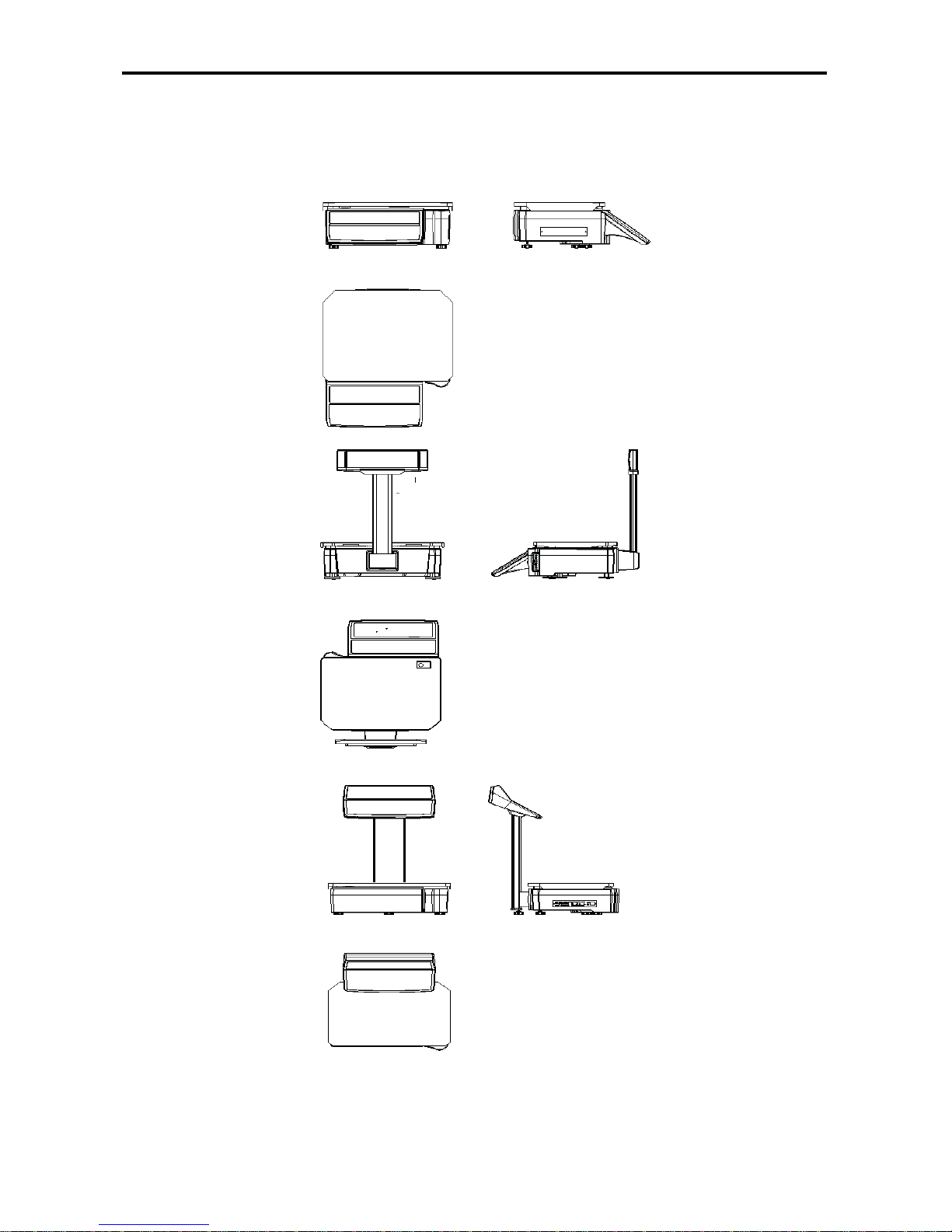
1.1 OVERALL VIEW
” Bench Type
” Pole Type
” Elevated Type
Page 6

SM 100 GENERAL
2
” Bench-CS Type
” Pole-CS Type
” Hand Type
Page 7
SM 100 GENERAL
3
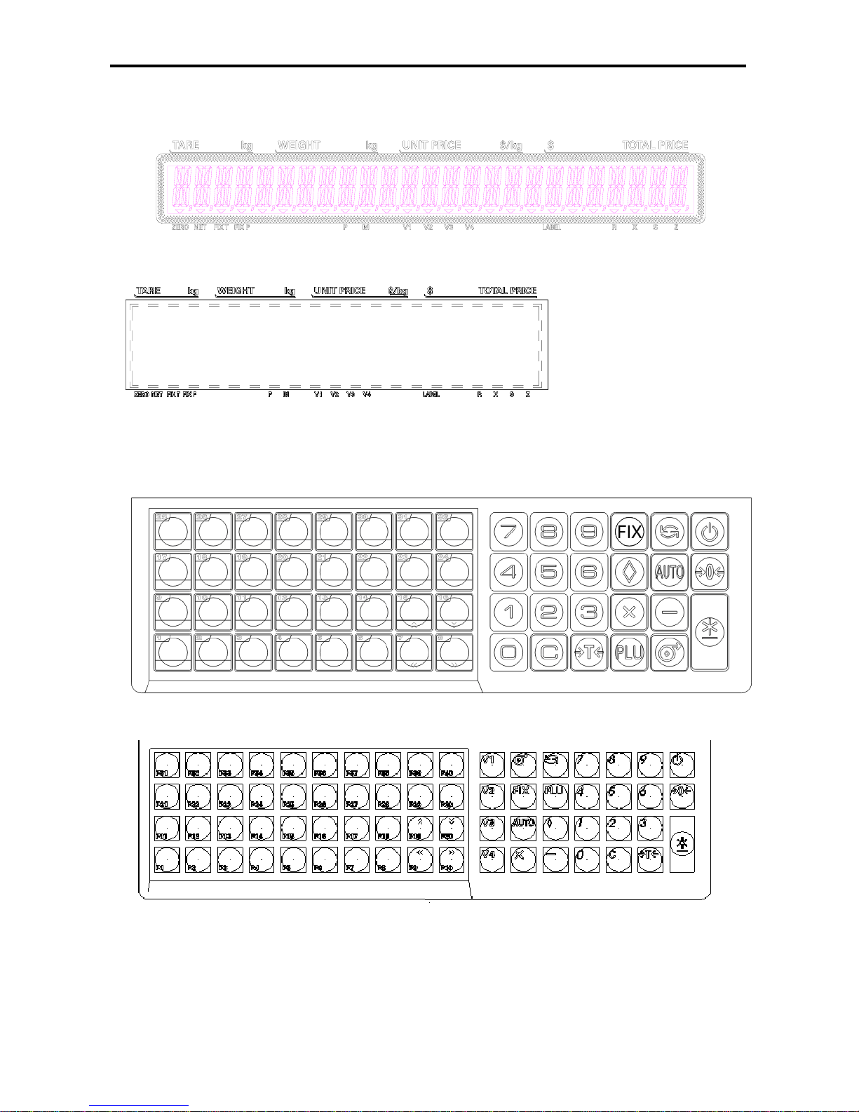
1.2 DISPLAY PANEL
” 25 digits × 19 segments TN type LCD
” 32 × 202 full dot Matrix Green LCD
1.3 KEY PANEL
” Preset Keys Type ------ B/P
32 Preset keys:
40Preset Keys:
Page 8
SM 100 GENERAL
4
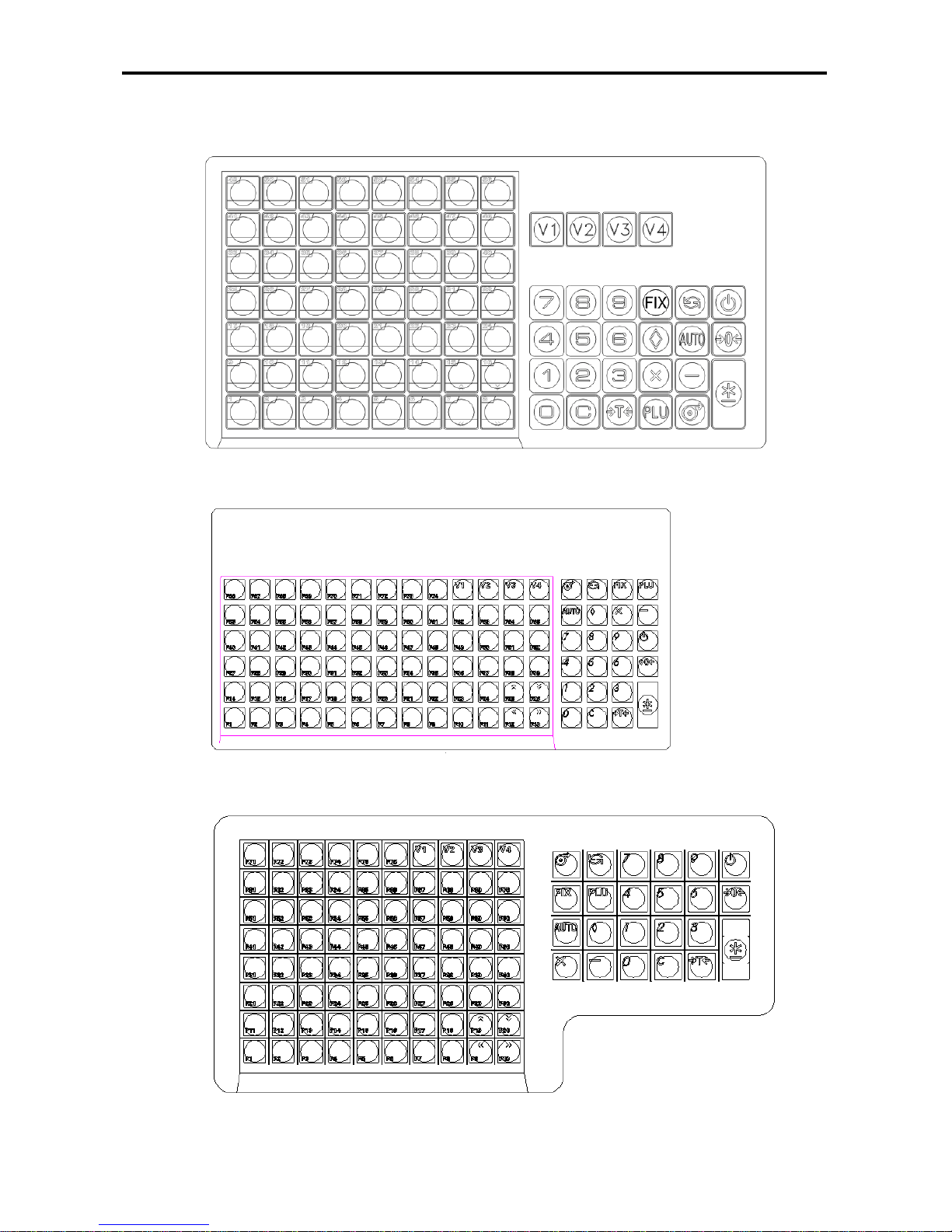
” 56 Preset Keys Type ------ PCS(New), PCS+ (New)
” 74 Preset Keys Type ------ EV, PCS(Old)
” 76 Preset Keys Type (Hanging)
Page 9
SM 100 GENERAL
5
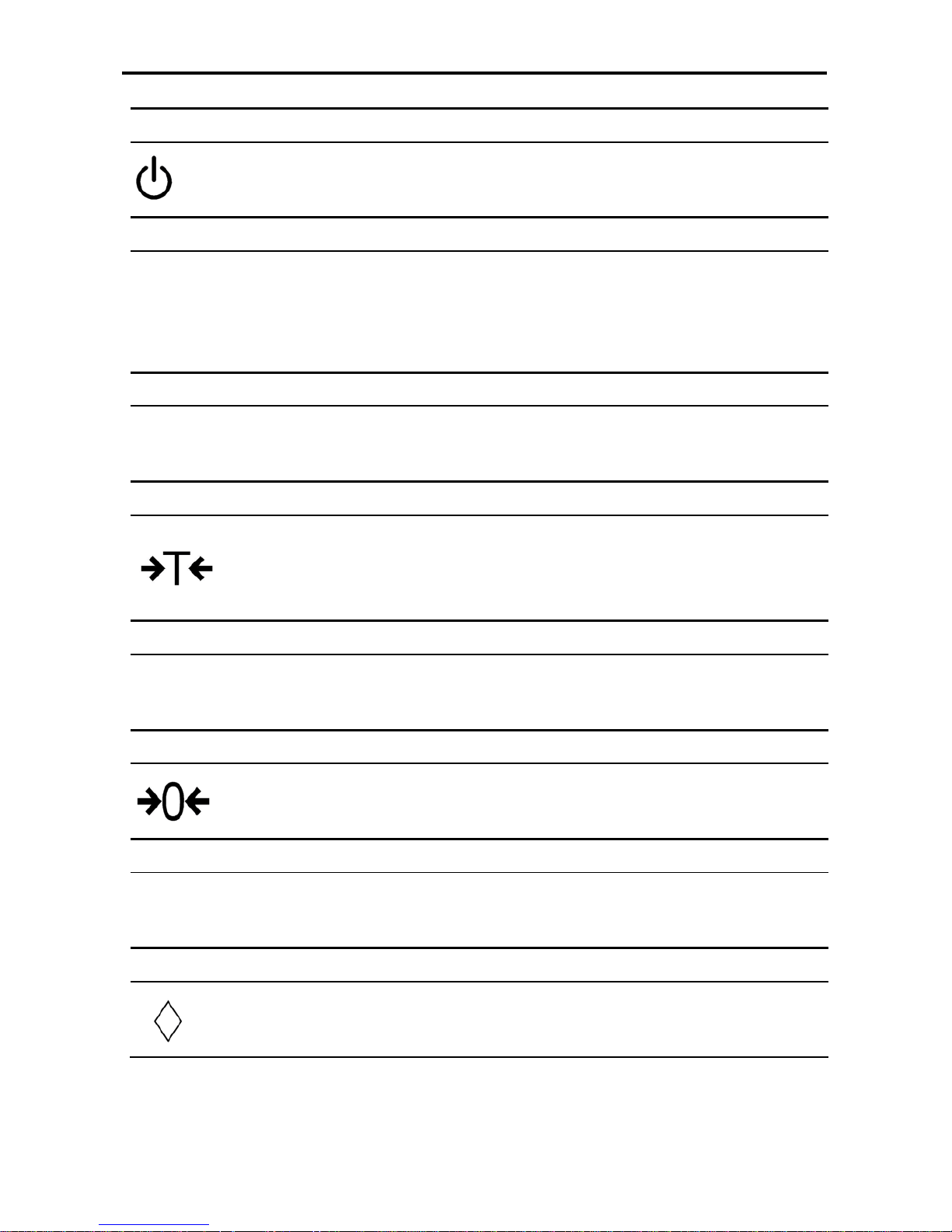
ON/OFF KEY
¬ Turn display "ON" or "OFF".
PRESET KEY
P1 ~ P40 (B/P)
P1 ~ P74 (EV)
P1~P32(BCS)
P1~P56(PCS)
P1~P76(H)
¬ Set up or call either unit price and tare value.
NUMERIC KEYS
0 ~ 9
¬ Enter numeric data.
TARE KEY
¬ Set or Clear Tare value.
¬ Select "NO" in S and Z Mode.
¬ Item test print in S Mode.
CLEAR KEY
C
¬ For Back space or Clear numeric value.
¬ Select "YES" in S and Z Mode.
RE-ZERO KEY
¬ Reset weight to ZERO.
PREPACK KEY
AUTO
¬ Switch Manual mode and Pre-pack mode alternatively.
(The mode status will be indicated in the P and M indicator.)
P - PRE-PACK MODE M - MANUAL MODE
CHANGE KEY
¬ Calculate the Changed Amount.
¬ Escape the Programming screen without saving data in S Mode.
Page 10
SM 100 GENERAL
7
MULTIPLLE KEY
X
¬ Register the number of Non-Weight products.
¬ Select programming item such as PLU data, Shop Name in S Mode.
¬ Select Report Type in X Mode.
¬ Select Data Transaction Type in Z Mode.
CLERK KEY
V1~V4
¬ Accumulate the Total Price.
VOID KEY
−
¬ Correct the sales data.
PLU KEY
PLU
¬ Call up PLU data in R Mode.
¬ Store the programmed data in S Mode.
FEED KEY
¬ Feed Label or Receipt paper
PRINT KEY
¬ Print out Label or Receipt.
Note: BCS or PCS stands for the scale with cassette.
Page 11
SM 100 GENERAL
8
MODE SELECT KEY
¬ Five Modes can be selected using this key.
• Indicator R - REGISTRATION MODE (All the sales transactions are
performed.)
• Indicator X - CHECK MODE (Printing out and sales report.)
• Indicator S - PROGRAM MODE (Programming preset data, such as
products, data, shop name, etc.)
• Indicator Z - TOTAL MODE (Clear sales data stored.)
• Indicator X (Blink) - Password Setting Mode (Set PASS WORD for X, S, Z
mode, set PASSWORD for PASSWORD MODE when all indicators(R, X, S,
Z) blink)
Decrease/Increase Specification Count key
,
¬ Decrease/Increase Only used when Setting SPEC 141 & 142
<<,>>
¬ Select parameter data such as SPEC data. Move cursor left or right.
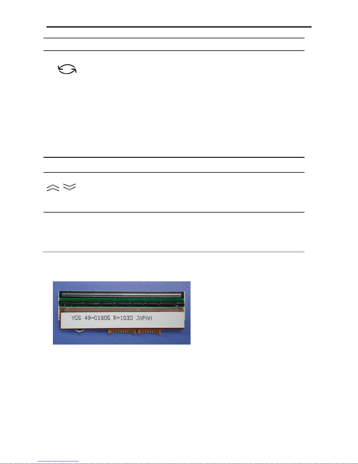
1.4 Thermal Printer Head
” Max Printing With: 56mm
Page 12
SM 100 GENERAL
9
1.5 FEATURES
„ Digital printing scale consists of electronic cash registers function and label printing function.
„ High-speed, high reliability thermal head printer.
„ Easy paper handing achieved special designed mechanism.
„ Built-in clock automatically updates data and time.
„ Quick response to weight changes.
„ Capacity and Resoultion
Capacity 3kg 6kg 12kg 15kg 30kg 60kg
Resolution 1/3000
1/3000S,
1/3000M,
1/6000S
1/3000
1/3000S,
1/3000M,
1/7500S
1/3000S,
1/3000M,
1/6000S
1/3000
Capacity 3lb 6lb 12lb 15lb 30lb 60lb
Resolution
1/3000S,
1/3000M
1/6000S
1/3000
1/3000S,
1/3000M,
1/7500S
1/3000S,
1/3000M,
1/6000S
1/3000S,
1/3000M,
1/6000S
1/3000S,
1/3000M,
1/6000S
Internal count: 1/90000.
„ Calibrating by software.
„ Customer and operator display (optional customer pole display).
SM-100:
25 digits x 19 segments TN type LCD with back-light for numeric digit and character display.
SM-100+:
32 x 202 full dot Martix Green LCD display.
„ membrane keys
a. ON/OFF key
b. 10 Numeric keys, to key in numeric data.
c. Preset keys, to preset PLU or function into the key.
d. 16 Operational keys, to perform various functional operations.
„ 18 data files, Department, Main Group, PLU, etc.
„ Various reports, PLU daily report, Sales daily report,24 hours daily report, etc.
„ Ethernet function.
„ Optional wireless Ethernet bridge.
„ RS232C interface for data communicate and barcode scanner connection.
„ Optional cash drawer.
„ Compact housing.
Page 13

SM 100 GENERAL
10
1.6 SPECIFICATION
1.6.1 Display
SM-100
25 digits × 19 segment TN type LCD with back-light for numeric digit and character display.
„ Tare weight display : 4 digits.
„ Weight display : 5 digits.
„ Unit price display : 6 digits.
„ Total price display : 7 digits.
SM-100+
32 x 202 full dot Martix Green LCD display.
„ Tare weight display : 4 digits.
„ Weight display : 5 digits.
„ Unit price display : 6 digits.
„ Total price display : 7 digits.
1.6.2 Operating Conditions
” Power Source : AC 110V,220V(+10%,-15%), 50~60Hz.
” Operating Temperature : -10 °C ~ +40 °C.
” Operating Humidity : 15% ~ 85% RH.
” Power Consumption : 70 W.
1.6.3 Dimensions
” Platter size
Bench, Pole and Elevated : 386(W) x 270(D) mm.
Bench-CS and Pole-CS : 359(W) x 277(D) mm.
Hanging : 274(d) x 35(h) mm.
” Overall size
a) Bench : 386(W) x 415(D) x 127(H) mm.
b) Pole : 386(W) x 478(D) x 480(H) mm.
c) Elevated : 386(W) x 416(D) x 550(H) mm.
d) Bench-CS : 380(W) x 360(D) x 162(H) mm.
e) Pole-CS : 380(W) x 380(D) x 509(H) mm.
f) Hand : 340(W) x 310(D) x 544(H) mm.
Page 14
SM 100 GENERAL
11
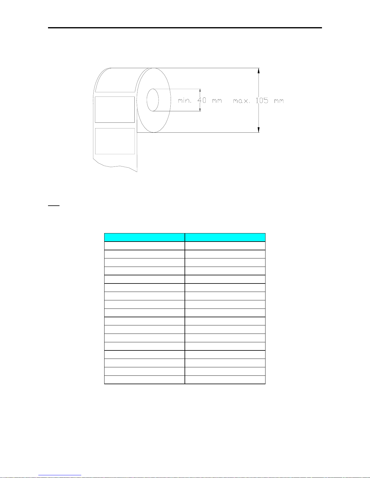
1.7 LABEL TYPE
The label diameter range is from 40 to 105 mm.
Note
: Labels must be winding outwards (on top backing paper) and not inwards (under backing paper) within the
core (see diagram above). If labels are wound wrongly, printing problem may result. We do not recommend the
use of varnish labels.
Label Type Dimension (mm)
T1 28 X 56
T2 31 X 56
T3 34 X 56
T4 40 X 56
T5 43 X 56
T6 46 X 56
T7 49 X 56
T8 55 X 56
T9 37 X 56
T10 40 X 56
T11 43 X 56
T12 49 X 56
S 28 X 37
A 46 X 37
B 46 X 37
C 62 X 37
F1 – F99 Free Format
Page 15
SM 100 INITIAL SETUP
13
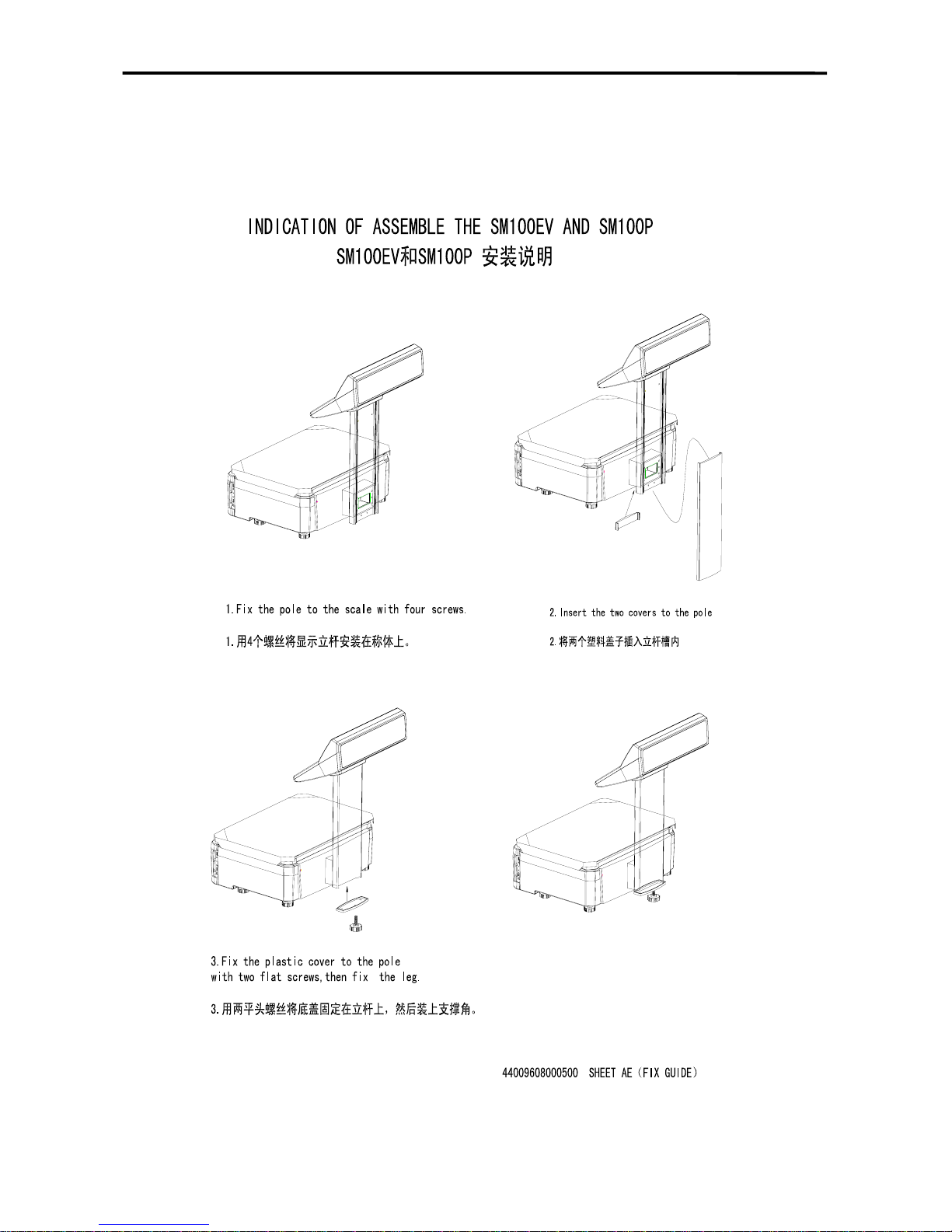
2. INITIAL SETUP
2.1 SETUP
Ü Indication of Assemble
Page 16
SM 100 INITIAL SETUP
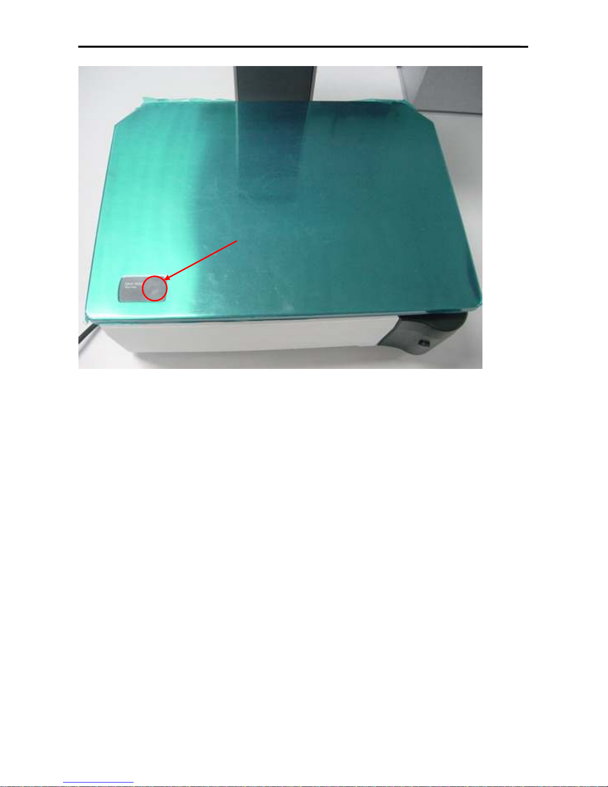
14
Ü Bubble Adjustment
Place the scale on the flat surface and adjust the four legs until the bubble on the level is in the
centre as shown above.
Bubble
Page 17
SM 100 INITIAL SETUP
15
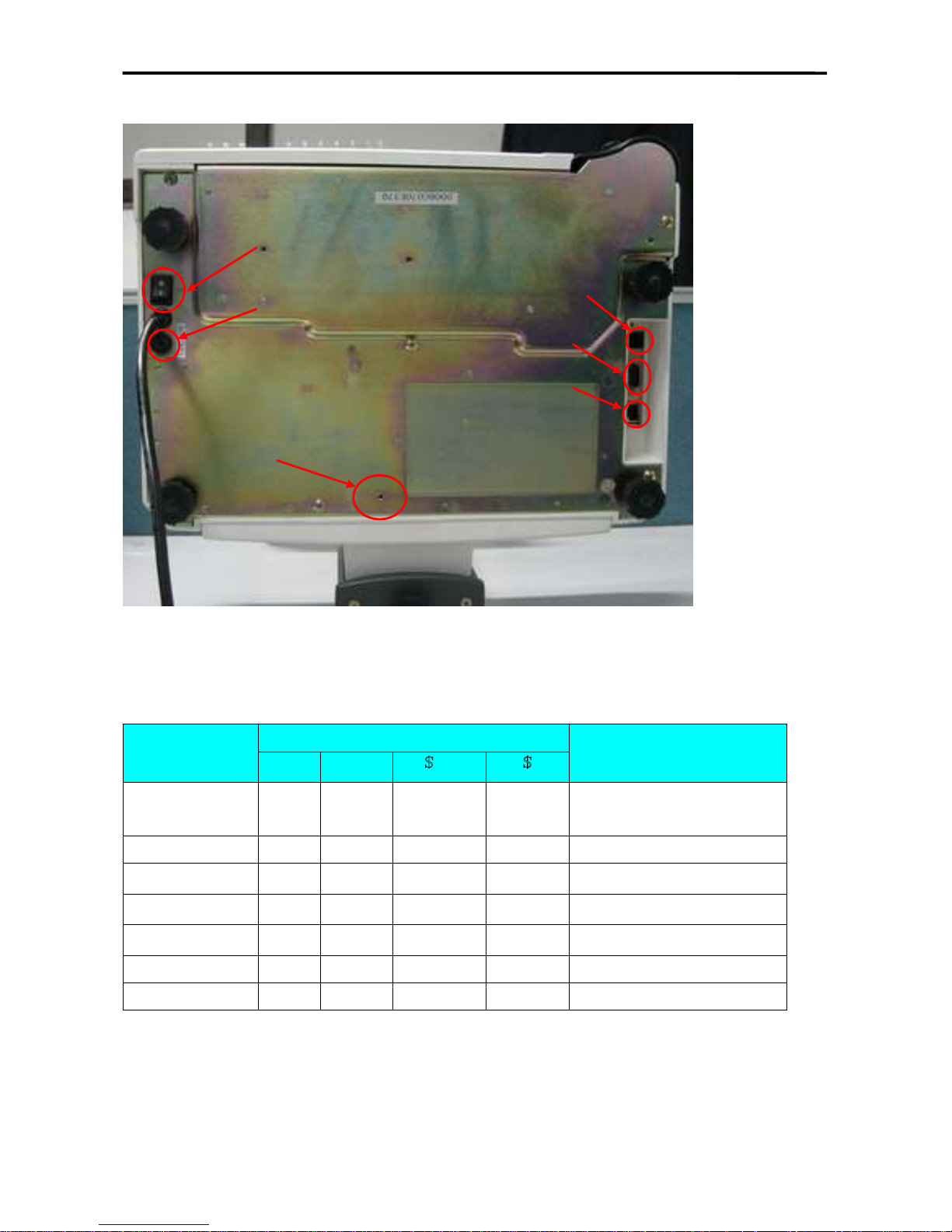
2.2 LOCATION OF SWITCHES AND CONNECTORS
2.3 MEMORY INITIALISATION
To clear all memory.
OPERATION
DISPLAY
REMARK
PT kg
/kg
Z1.0 RESET SALES DAILY
Z mode.
Lamp Z turns on.
[Rezero]+[2][3][0] CLEAR PLU FILE PLU file.
[]
CLEAR VENDER DATA
Vender transaction data.
[]
CLEAR REPORT FILES
Report files.
[]
CLEAR MEMORY DATA
All files in memory.
[*] CLEAR MEMORY Y-C N-T [C] to clear file data,[T] to quit.
[C] or [T] Z1.0 RESET SALES DAILY Return to Z mode.
Span Switch
Power
Switch
Cash Drawer Port
RS232 Port
Ethernet Port
Fuse
Holder
Page 18
SM 100 INITIAL SETUP
16
2.4 DEFAULT SPECIFICATION SETTING
Default SPEC setting of individual country.
(Please turn on the span switch before proceed this process.)
Ü Country Set
OPERATION
DISPLAY
REMARK
PT kg
/kg
Z1.0 RESET SALES DAILY Z mode.Lamp Z turns on.
[Rezero]+[8][8][2][2] SPEC 2-STD COUNTRY Set country setting.
[>>] SPEC 3-CN COUNTRY
[>>],[<<] or [X] to select country.[*]
to update country setting.
[*] LOAD DEFAULT SPEC Y-C N-T
[C] to load default SPEC setting,[T]
to skip.
[C] SCALE
TYPE
POLE
Set scale type.
[X] SCALE
TYPE
BENCH
[X],[] to select type,[*] to update
type setting.
[*] SCALE
CAP.
3KG
Set scale capacity.
[X] SCALE
CAP.
6KG
[X],[ ] to select capacity,[*] to
update capacity setting.
[*] SCALE
RES.
1/3000S
Set resolution.
[X] SCALE
RES.
1/3000M
[X],[ ] to select resolution,[*] to
update resolution setting.
[*] CLEAR MEMORY Y-C N-T [C] to clear memory,[T] to skip.
[C] Z1.0 RESET SALES DAILY Return to Z mode.
Note 1: For the first using of SM-100,Please take this operation for initialization.
Note 2: Enter a number that represent a country in the country list (refer to the table below) to
initialise and country set.
Page 19
SM 100 INITIAL SETUP
17
COUNTRY LIST
No. Country Code Country No. Country Code Country
0 AA Japan 41 SA Saudi Arabs
1 U1 U.S.A. 42 IC Iceland
2 STD Standard 43 IE Indonesia
3 CN China 44 CB Cuba
4 HK Hong Kong 45 KY Kenya
5 TW Taiwan 46 IR Israel
6 EX Export 47 VY Slovenia
7 KE Korea 48 MS Malaysia
8 AR Australia And New Zealand 49 SN Spain
9 SF South Africa 50 VZ Venezuela
10 CS Cyprus 51 CO Croatia
11 GC Greece 52 MA Macedonian
12 TU Turkey 53 FR France
13 CV Czech Republic 54 WG Germany
14 HG Hungary 55 BL Bulgaria
15 PL Poland 56 BW Botswans
16 UR Russia 57 CP Comores
17 AS Austria 58 LS Lesotho
18 DM Denmark 59 MU Mauritius
19 FL Finland 60 MW Malawi
20 NW Norway 61 MZ Mozambique
21 SD Sweden 62 NM Namibia
22 PG Portugal 63 RE Reunion
23 UK United Kingdom 64 SH Seychelles
24 IL Ireland (Kg) 65 SW Swaziland
25 IL (LB) Ireland (Lb) 66 WZ Zimbabwe
26 CA Canada (Kg) 67 ZW Zambia
27 CA (LB) Canada (Lb) 68 AE U.A.E
28 AG Argentina 69 TT Trinidad and Tobago
29 MX Mexico 70 UD Uganda
30 BZ Brazil 71 LV Latvia
31 CE Chile 72 CVS Slovakia
32 EA Egypt 73 SK Sri Lanka
33 JD Jordan 74 SV Slovenia
34 LN Lebanon 75 UA Ukraine
35 IRN Iran 76 KZ Kazakhstan
36 CR Canary Islands 77 IT Italy
37 TL Thailand 78 SZ Switzerland
38 EC European Community 79 ID India
39 NL Netherlands 80 CD New Caledonia
40 BG Belgium
Page 20
SM100 CALIBRATION
18
3. CALIBRATION
Prior to Calibration, please refer that the specification indicating weight capacity, minimum
graduation, and load cell sensitivity are correctly set.
Caution:
” It can only work when SPAN SWITCH is on (ENABLE).
Before Calibrating, please enter Z mode.
3.1 CALIBRATION OPERATION
OPERATION
DISPLAY
REMARK
PT kg
/kg
Press SPAN SWITCH Z1.0 RESET SALES DAILY
SPAN SWITCH is on
(ENABLE).
[Rezero]+[8][7][1][5] CAL 00
Enter [8][7][1][5] while
depressing [Rezero].
Ensure no weight on
platter,[*]
------
Calibrating zero point.
After storing the zero
Point ‘IR’ count
CAL SP
Put full capacity weight
on platter.[*]
------
Calibrating Span.
After calibration Z1.0 RESET SALES DAILY
Go back to Z mode. Lamp Z
always light.
Page 21
SM100 CALIBRATION
19
3.2 EXIT CALIBRATION
OPERATION
DISPLAY
REMARK
PT kg
/kg
Press SPAN SWITCH Z1.0 RESET SALES DAILY
SPAN SWITCH is
on(ENABLE).
[Rezero]+[8][7][1][5] CAL 00
Enter [8][7][1][5] while
depressing [Rezero].
[T] Z1.0 RESET SALES DAILY
Escape to Z mode. Lamp Z
always light
[Rezero]+[8][7][1][5]
[*]
CAL 00
------
The ‘IR’ count will be taken as
the zero point ‘IR’ count.
After storing the zero
Point ‘IR’ count
CAL SP
Calibrating Span.
[T] Z1.0 RESET SALES DAILY
Escape to Z mode. Lamp Z
always light.
Page 22
SM 100 SOFTWARE SETTING
20
4 SOFTWARE SETTING
4.1 SOFTWARE VERSION UPGRADE
Æ Update Method Introduction
SM-100 use flash RAM instead of EPROM for the main program storage of the scale.
Before the boot program Version 1.10, we just have one method to update the scale’s
software: PC to scale via RS232 interface.
After the boot program Version 1.10 (including V1.10), we add a new method to update
the scale’s software: update the scale by ethernet. So you can choose either method
between these two ones to update your scale.
Now we will set two parts to introduce the steps of these two updating methods.
Æ Update Steps Introduction
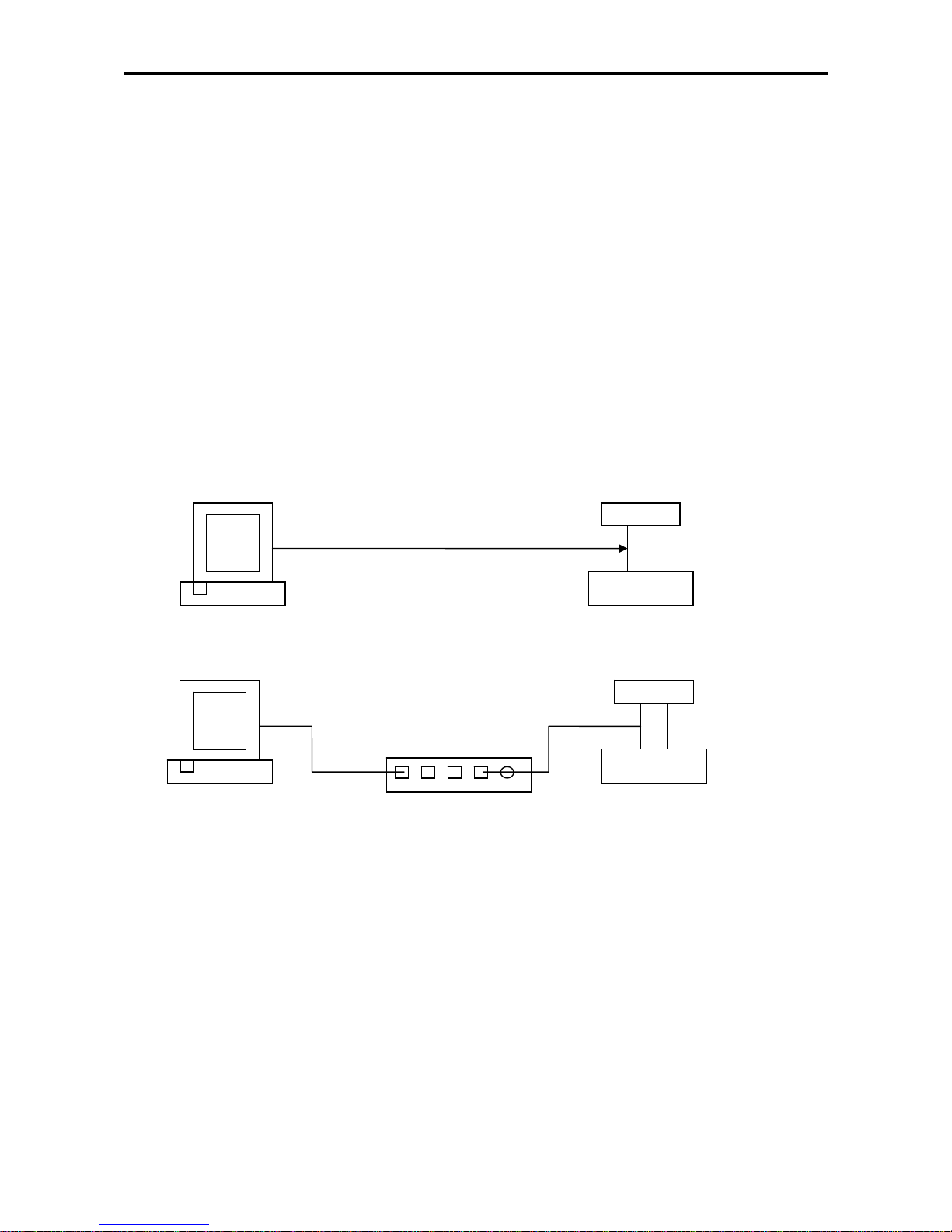
I. Ethernet Update Method
1. Cable & Connection
There are also two ways to connect the PC and the scale in updating the scale by
ethernet.
1) PC to Scale
2) Connect by Hub
PC
Sm-100
Crossing Twisted Cable
PC
Sm-100
Normal Normal
Twisted Cable Twisted Cable
HUB
Page 23
SM 100 SOFTWARE SETTING
21
These two twisted cable obey the EIT/TIA 568 standard.
T568A line series
1 Green &White
2 Green
3 Orange & White
4 Blue
5 Blue & White
6 Orange
7 Brown & White
8 Brown
crossing twisted cable: one end with T568A line series, another with T568B line
series
normal twisted cable: two ends both with T568B line series
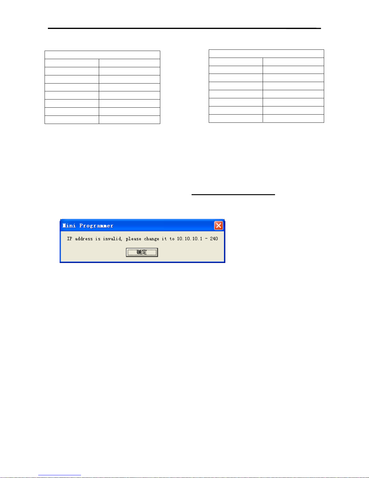
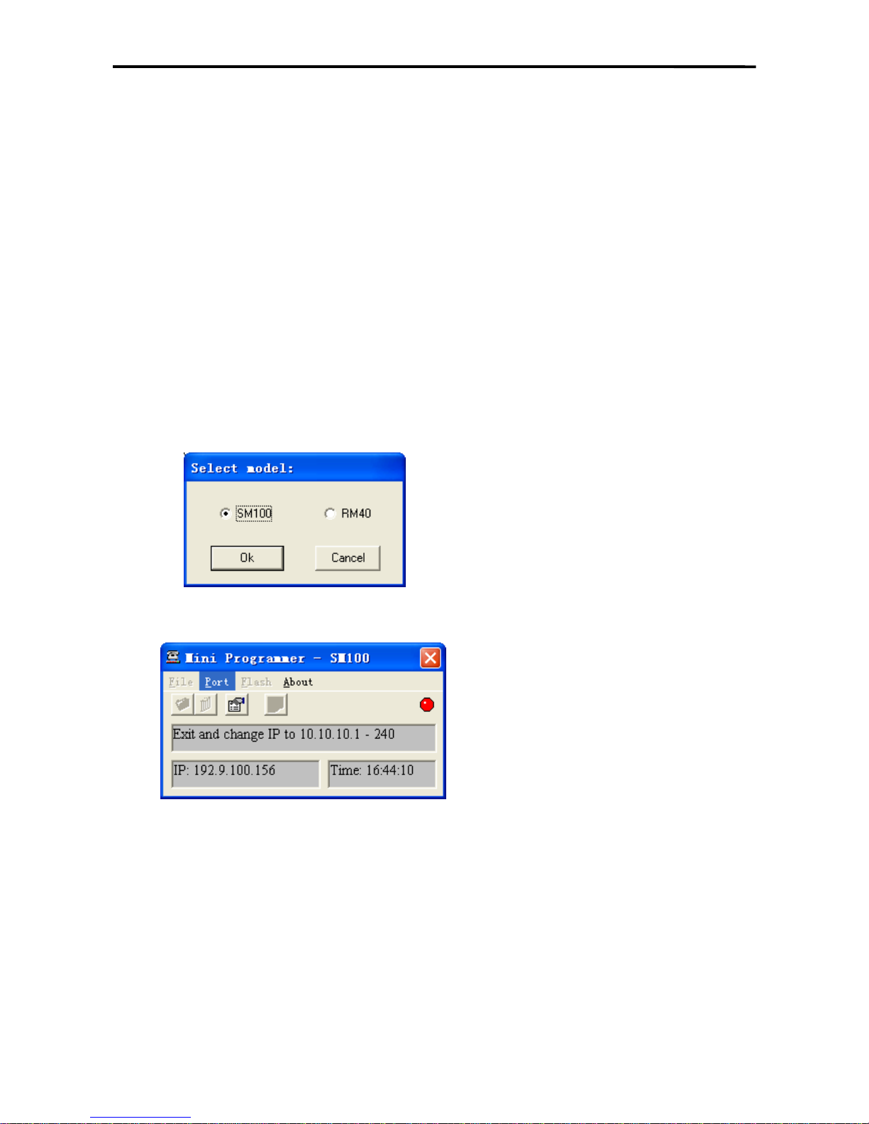
2. PC Setting & Programmer Version
We use “Mini Programmer (Version 2.00)” as the tool to update the scale. As it
needs a default visual IP address for the PC by this kind of update method, You must
set your PC’s IP address within the range of 10.10.10.1-----10.10.10.240
, before you
start the software to update the scale.
If you don’t set the IP address like this, you can see an alarm window as Pic. 1 when
you start “Mini Programmer”.
Pic. 1
3. Updating Steps
1) How to start ethernet updating?
A. Turn on the switch on the bottom of the scale.
B. Power off the scale by pressing On/Off Key.
C. After that, press and hold [Re-Zero] and [Preset 22], then start the scale by
pressing the On/Off Key.
D. The screen will display the version of the current boot program for two seconds.
E. Only in new versions(version of the boot program newer than 1.10),
you
can choose 2-ethernet.
2) Display on the scale’s screen
A. If you choose 2 and the scale’s connection is correct, it will display “waiting for
connect”.
B. Then the message on the scale’s screen is “getting IP address”.
C. After this, it will display “001 scale ready update”.
D. You can’t stop it unless you press On/Off key. If you want to continue
updating. You also don’t need to press any key on the scale until Mini
Programmer begin to run.
T568B line series
1 Orange & White
2 Orange
3 Green &White
4 Blue
5 Blue & White
6 Green
7 Brown & White
8 Brown
Page 24
SM 100 SOFTWARE SETTING
22
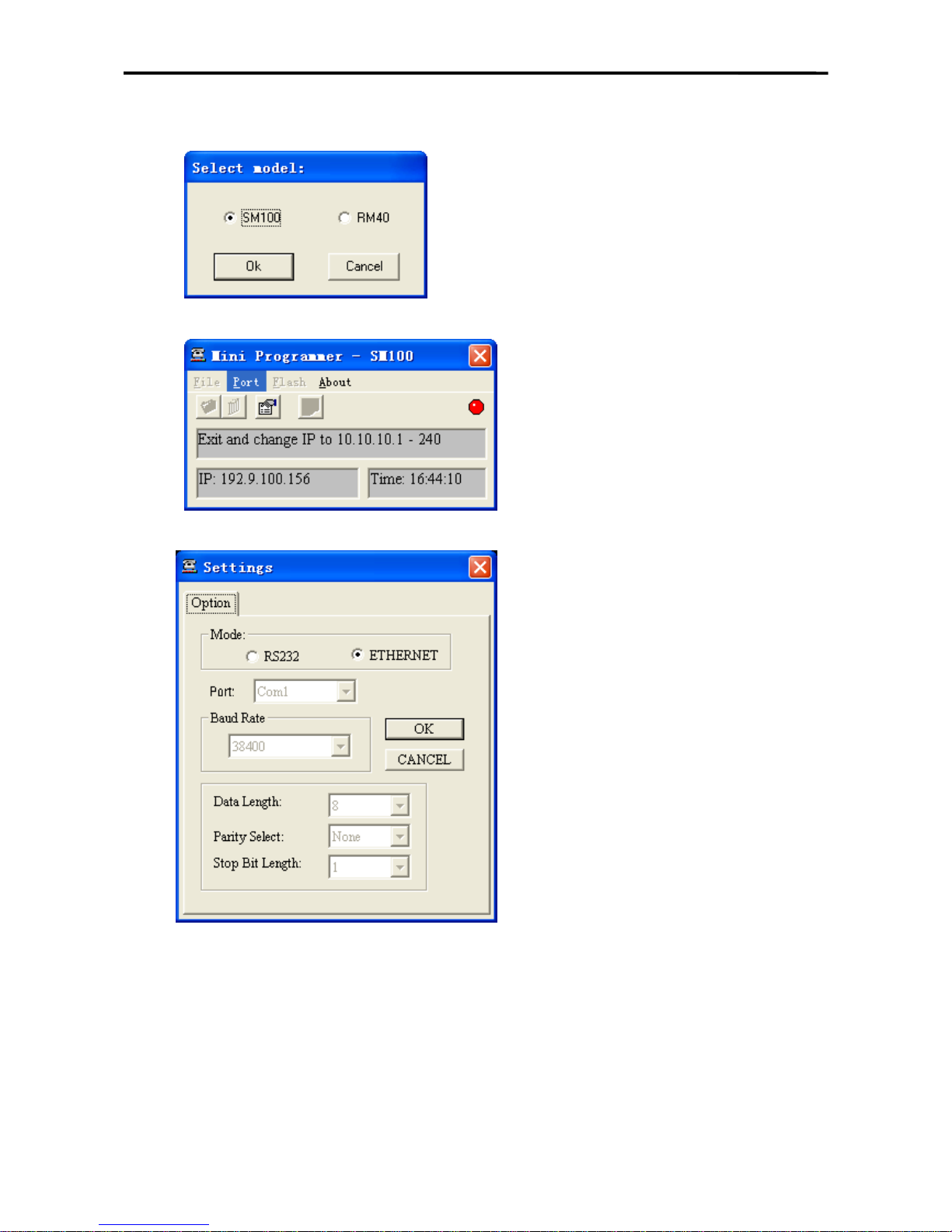
3) How to upload the scale by Mini Programmer?
A. Select SM-100 and press “ok”
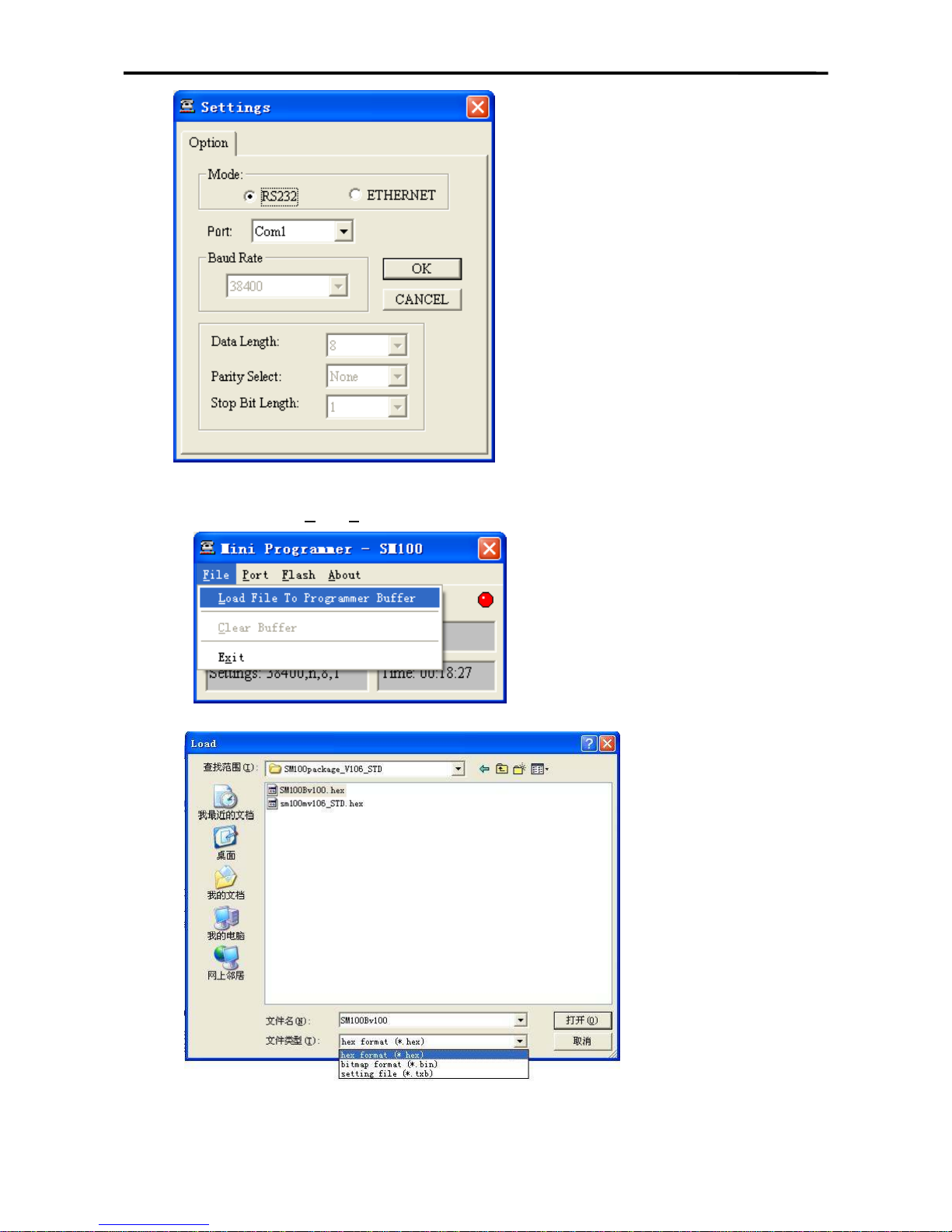
B. Set the port
Select “ethernet” and press “OK”
Page 25

SM 100 SOFTWARE SETTING
23
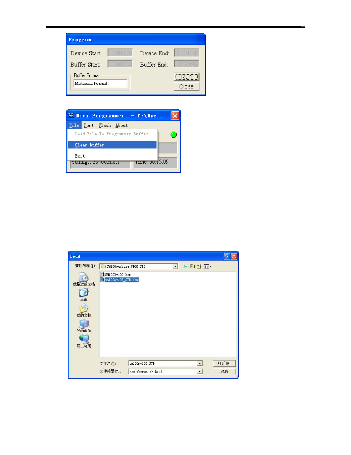
C. Download boot program and update the scale
Select menu “F
ile->Load File To Programmer Buffer”
Open the source file of boot program (e.g. sm100bv100.hex)
You can see a speed mode select window here.
Select menu “F
lash->Program”
Notice: The message “001 scale ready update” must be displayed on the
screen of the scale before pressing the “run” button.
Page 26
SM 100 SOFTWARE SETTING
24
After the transmission has completed, select menu “File->Clear Buffer”.
Notice: 1.If the boot program of this version is already in the scale, you don’t
need to upload it again, skip it and upload the main program.
2.If the scale is updated from 1.xx to 2.xx,firstly you must update the
boot program of the version.
D. Download main program file
You must power off the scale and start the ethernet upload method again when
you have finished a program uploading.
The steps of uploading the main program file is also like uploading the boot
program file. The file you need to open is like Pic. 2
Pic. 2
Page 27
SM 100 SOFTWARE SETTING
25
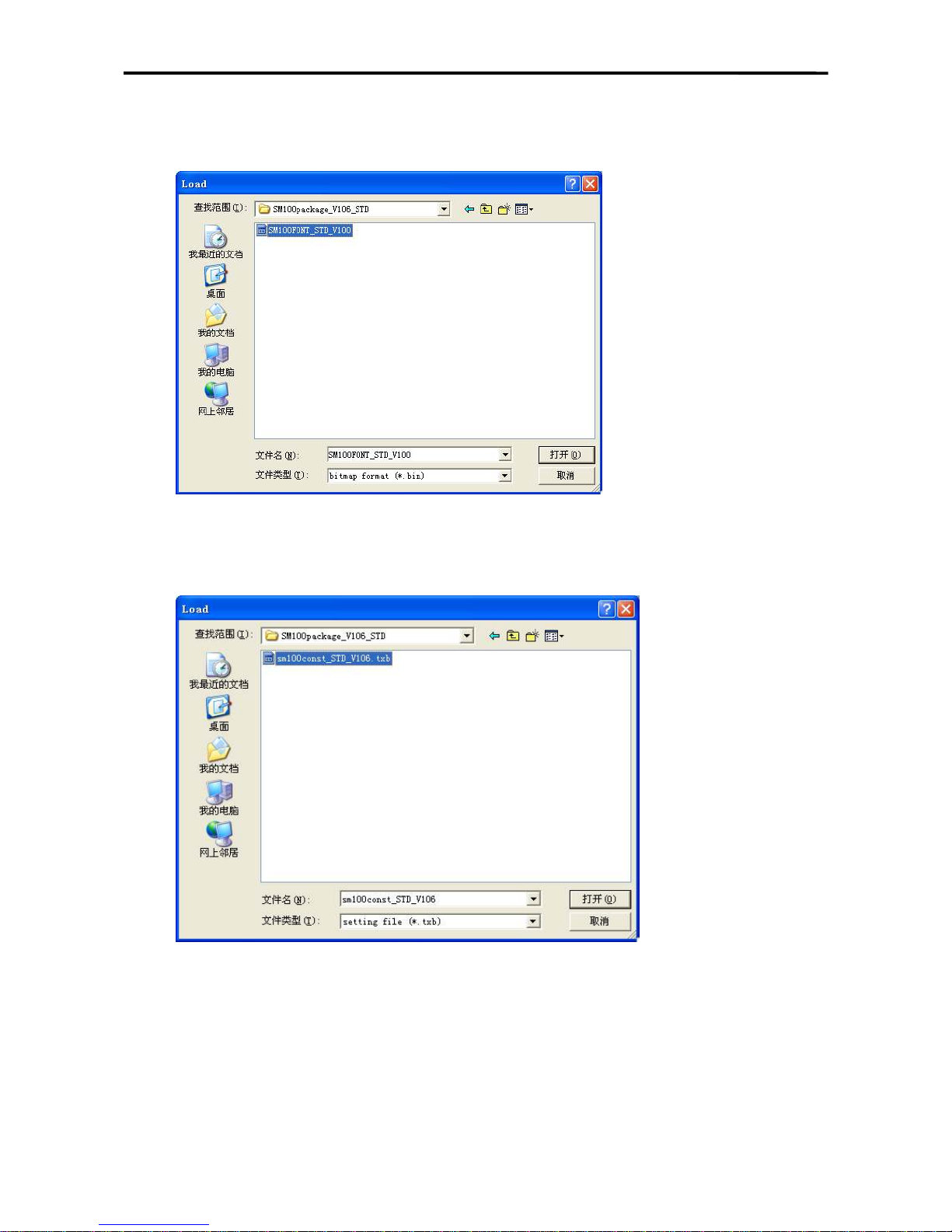
E. Download word-stock file
The steps of uploading the word-stock file is also like uploading the boot program
file. The file you need to open is like Pic. 3
Pic. 3
F. Download const text file
The steps of uploading the const text file is also like uploading the boot program.
The file you need to open is like Pic. 4
Pic. 4
G. Exit Mini Programmer
Note: please update the scale according to sequence above.
Page 28
SM 100 SOFTWARE SETTING
26
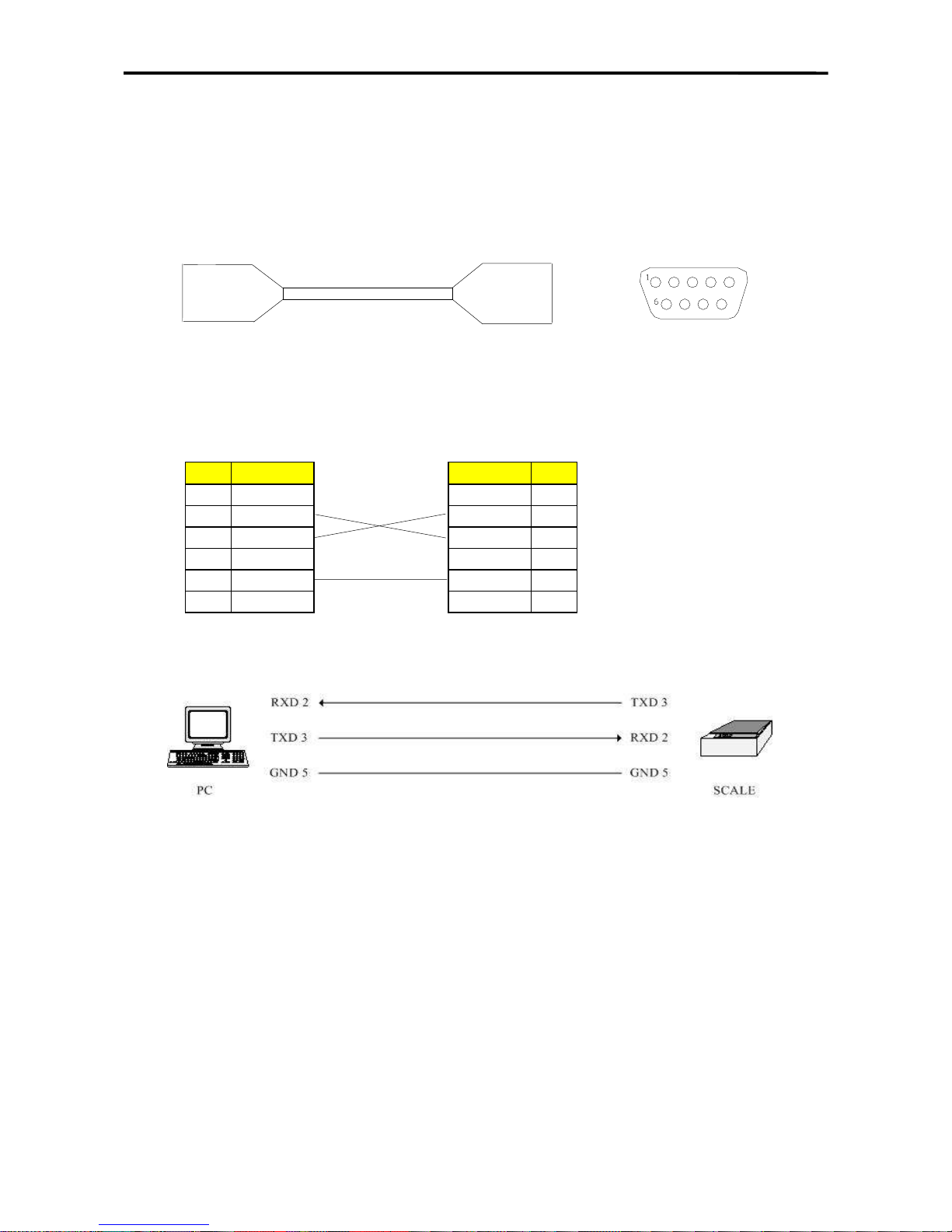
RS232C Method
4. Cable Connection
3 Pins are used for data transmission between PC and SM-100
9 Pin D-Sub Female Connectors for this cable:
PC Serial Port SM-100 RS-232C
9 Pin D-Sub (Female) 9 Pin D-Sub (Female)
Pin Signal Signal Pin
1 N.C. N.C. 1
2 RXD RXD 2
3 TXD TXD 3
4 N.C. N.C. 4
5 GND GND 5
6 - 9 GND N.C. 6 - 9
Page 29
SM 100 SOFTWARE SETTING
27
5. Update Steps
1) How to start RS232C updating
A. Turn on the switch on the bottom of the scale.
B. Power off the scale by pressing the On/Off Key.
C. After that press and hold [Re-Zero] & [Preset 22], then start the scale by press
ing the On/Off Key.
D. It will display the version of the current boot program for two seconds.
E.
Ü If the scale boot version is newer than 1.10, it will display a updating method
choice like “1-RS232 2-ETHERNET” on the screen. you can press Numeric 1
to choose 1-RS232C.
Ü If the boot version is older than 1.10, the scale will not display the choice.
F. Then the Scale will display “PROGRAM”. You can’t stop it, unless you press
Tare or On/Off Key.
2) Start Mini Programmer
1. Select SM-100 and press “Ok”
2. Set the Port:
Select RS232 and press “OK”
Page 30
SM 100 SOFTWARE SETTING
28
3. Download the boot program and update the scale
Select menu “F
ile->Load File To Programmer Buffer”
Open the source file of the boot program (e.g. sm100bv100.hex)
Page 31

SM 100 SOFTWARE SETTING
29
Select menu “Flash->Program”
Notice: The message “001 scale ready update” must be displayed on the
scale before pressing the “run” button.
After the transmission has completed, select menu “File->Clear Buffer”.
Notice: If the boot program of this version is already in the scale, you don’t
need to upload it again, skip it and upload the main program.
Page 32

SM 100 SOFTWARE SETTING
30
4. Download main program file
You must power off the scale and start the ethernet upload method again when
you have finished a program uploading.
The steps of uploading the main program file is also like uploading the boot
program file. The file you need to open is like Pic. 2
Pic. 2
5. Download word-stock file
The steps of uploading the word-stock file is also like uploading the boot program
file. The file you need to open is like Pic. 3
Pic. 3
6. Download const text file
The steps of uploading the const text file is also like uploading the boot program.
The file you need to open is like Pic. 4
Page 33

SM 100 SOFTWARE SETTING
31
Pic. 4
7. Exit Mini Programmer
Page 34

SM 100 SOFTWARE SETTING
32
4.2 SPECIFICATION SETTING
Before Specification setting, please press the mode button to enter Z mode.
The detail specification list , please see the appendix.
4.2.1 Customer SPEC Setting
To change setting of the Customer SPEC if there are some SPEC setting in it need to be alter.
OPERATION
DISPLAY
REMARK
PT kg
/kg
Z1.0 RESET SALES DAILY
Z mode.
Lamp Z turns on.
[Rezero]+[1][4][1] SPEC 000
XXX
(setting)
XXX
(former)
Enter [1][4][1] while depressing
[Rezero].
XXX:SPEC data
[]
SPEC 001 XXX XXX
[]key only increase specification
count, it does not update SPEC data.
[]
SPEC 000 XXX XXX
[]key only decrease specification
count, it does not update SPEC data.
[1][7]
[X]
SPEC 000
SPEC 017
017
XXX
XXX
XXX
It goes to a designed specification
count.
(000~441 is enabled)
[>>] SPEC 017 XXX XXX
[>>] key select SPEC data.
Move cursor right.
[<<] SPEC 017 XXX XXX
[<<] key select SPEC data.
Move cursor left.
[1]
[*]
SPEC 017
SPEC 018
001
XXX
XXX
XXX
[C] SPEC 018 000 XXX Clear the enter data.
[PLU]
* Note 1
Z1.0 RESET SALES DAILY
Store the updated specification and
escape to Z mode.
* Remark: The Weight in the display window will display the SPEC number. The Unit Price
window will display the new value setting entered. The Total Price window will
display the old value setting. The selection you have made will be highlighted in the
dot matrix display. Please use [] to increase spec count, [] to decrease spec count,
[*] to store a new value and [PLU] to save spec setting.
4.2.2 Weight & Measurement SPEC Setting
Page 35

SM 100 SOFTWARE SETTING
33
To change the setting of the Weight & Measurement SPEC if there are some SPEC need to alter.
(Please turn on the span switch when using this process)
OPERATION
DISPLAY
REMARK
PT kg
/kg
Press SPAN
SWITCH
Z1.0 RESET SALES DAILY SPAN SWITCH is on(ENABLE).
[Rezero]+[1][4][2] SPEC 600
XXX
(setting)
XXX
(former)
Enter [1][4][2] while depressing
[Rezero].
XXX:SPEC data
[]
SPEC 601 XXX XXX
[]key only increase specification
count, it does not update SPEC data.
[]
SPEC 600 XXX XXX
[]key only decrease specification
count, it does not update SPEC data.
[6][1][5]
[X]
SPEC 600
SPEC 615
615
XXX
XXX
XXX
It goes to a designed specification
count.
(600~709 is enabled)
[>>] SPEC 615 XXX XXX
[>>] key select SPEC data.
Move cursor right.
[<<] SPEC 615 XXX XXX
[<<] key select SPEC data.
Move cursor left.
[1]
[*]
SPEC 615
SPEC 616
001
XXX
XXX
XXX
[*] key to update specification,
increase specification count.
[2] SPEC 616 002 XXX
[C] SPEC 616 000 XXX Clear the enter data.
[PLU]
* Note 1
Z1.0 RESET SALES DAILY
Store the updated specification and
escape to Z mode.
Note 1: If press [T] key, it does not store the updated specification and escape to Z mode.
* Remark: The Weight in the display window will display the SPEC number. The Unit Price
window will display the new value setting entered. The Total Price window will
display the old value setting. The selection you have made will be highlighted in the
dot matrix display. Please use [] to increase spec count, [] to decrease spec count,
[*] to store a new value and [PLU] to save spec setting.
Page 36

SM100 ADJUSTMENT
34
5. ADJUSTMENT
5.1 PEEL SENSOR VOLTAGE AND LABEL SENSOR SENSITIVITY ADJUSTMENT
LOCATION OF PEEL AND LABEL SENSOR
Page 37

SM100 ADJUSTMENT
35
5.1.1 Peel Sensor Voltage
To set the peel sensor voltage if the peel sensor is not working normally in some situations like temperature
and humidity change.
OPERATION
DISPLAY
REMARK
PT kg
/kg
Z1.0 RESET SALES DAILY
Z mode.
Lamp Z turns on.
[Rezero]+[5][1][5] PEEL PFD 0.5 0.0
Enter [5][1][5] while depressing
[Rezero].
/kg window displays label paper
peel sensor voltage, window
displays new setting value.
[T] Z1.0 RESET SALES DAILY [T] key to exit.
5.1.2 Label Sensor Sensitivity
When the label came out three or more when feeding or printing, the sensitivity of the sensor need to be
adjusted to sense the gap between the label better. There is a variable resistor near the sensor. Adjust it to
increase or decrease the sensitivity. Clockwise is to increase the sensitivity and anti-clockwise is to decrease
the sensitivity.
Adjust here for sensor
Page 38

SM100 ADJUSTMENT
36
OPERATION
DISPLAY
REMARK
PT kg
/kg
Z1.0 RESET SALES DAILY
Z mode.
Lamp Z turns on.
[Rezero]+[5][1][6] GAP PFD 2.0 3.1
Enter [5][1][6] while
depressing [Rezero].
/kg window displays
label paper gap sensor
voltage, window
displays new setting
value.
[T] Z1.0 RESET SALES DAILY [T] key to exit.
Page 39

SM100 ADJUSTMENT
37
5.2 ADJUSTMENT OF PRINTING POSITION
This function is used to adjust the print position on label.
OPERATION
DISPLAY
REMARK
PT kg
/kg
Z1.0 RESET SALES DAILY
Z mode.
Lamp Z turns on.
[Rezero]+[5][1][4] ADJ PFD 0 0
Enter [5][1][4] while depressing
[Rezero].
/kg window display old setting,
window display new setting.
[1][0] ADJ PFD 0 10
To move up the point position on
label, enter the new value by numeric
key (Ex. 10 dots).
[1][0][]
ADJ PFD 0
10
If you want to move down the print
position, please enter the new value
by numeric key (Ex. 10dots), and
then press [−
] key.
[PLU] 0.000 0.000 0.00 0.00
Save the feed setting.
[T] Z1.0 RESET SALES DAILY
If you want to exit without saves the
setting, press [T] key to exit.
PRINTING TOO HIGH CORRECT POSITION PRINTING TOO LOW
(ADJUST DOWNWARD) (ADJUST UPWARD)
Page 40

SM100 ADJUSTMENT
38
5.3 VOLTAGE CHECKPOINT
There are several voltage checkpoints on the PCB boards. Below are some reference voltage points that are
commonly use.
VOLTAGE POINT VOLTAGE PURPOSE
VCC 3.3 V Provide voltage for most of the IC
VTH 24 V Provide voltage mainly to the thermal head
VBB 3 V Provide backup voltage for the RAM IC
HVcc 5 V
The tolerance of all the voltage is about ± 5% except V
TH
is +2% and -5%
Page 41

SM100 INTERFACE
39
6. INTERFACE
6.1 PC INTERFACE
SM 100 can be connect to PC through Ethernet interface and RS232C. See below for the connection
method.
CONFIGURATION OF PC ETHERNET CARD
Window version client driver
Any Ethernet cards can be used for PC running the Window version client driver
Windows 98
My Computer →
Control Panel → Network→TCP/IP of Ethernet card (Select Properties)
IP address : 192.168.1.XXX ------ XXX - can be any number. But preferable 100 to 255.
Submask : 255.255.255.0
Above IP address is use as a standard address to use for SM 100 Ethernet communication.
If whatever reason, the IP address had to be change, it may do so. But the scale IP address had to be
change at the SM 100 scale also so that they are within the same network. Eg. If the computer IP
address is 192.168.1.XXX, the SM 100 scale IP address has to be change to 192.168.1.XXX. The last
three digits of the IP address should not be similar within the computer and scales at all time. As can
see the first three set of number of the IP address of the computer and scale must be the same.
Page 42

SM100 INTERFACE
40
Before setting the SPEC setting of the scale, please check below.
6.2 SCALE ETHERNET ADDRESS
The main board have a Scale Ethernet Address that is set during production. This address is a
hardware setting for Ethernet communication. But when changing a new main board, the new main
board did not have any this address. If the scale is using Ethernet communication, a Scale Ethernet
Address is needed apart from software IP address. Please take note that the Scale Ethernet Address
can only input once after saving. Please view and note down the Scale Ethernet Address of the old
main board before changing the new main board. Below procedure is to view and input the Scale
Ethernet Address. Please turn on the span switch before proceed.
KEY TO PRESS DISPLAY OPERATION
PT kg
/kg
Go to Z mode Z1.0 RESET SALES Daily At Z mode
[REZERO] +
[0][6][1][2]
ETHER NET ……. ……. Viewing of Ethernet address
For new main board, it can
act as input of the address if
the address shown ……..
Else it would not let you to
input
.
[0][0][0][6][C][0]
[0][0][0][0][2]
[4]
ETHER NET 0006C 0000024 For input only. Enter
Ethernet address e.g.
0006C 0000024
[PLU] Z1.0 RESET SALES Daily Save address and escape to Z
mode. After saving it will
not be able to input again.
[T] Z1.0 RESET SALES Daily Escape to Z mode without
saving.
Power off the scale
Turn off the power and do
the memory clear process.
* IMPORTANT : Please take note that this is a one time setting. It cannot be change after setting
it. Please check the old address and input accordingly. As same internal Ethernet
address in a network may conflict during communication.
6.3 SCALE IP ADDRESS
Page 43

SM100 INTERFACE
41
This is to set the IP address for PC communication using Ethernet for specific IP address. It should
not be confused with the Scale Ethernet Address as above. The Scale Ethernet Address is mainly for
hardware and Scale IP Address is for software. The software when communicating to the scale must
specify the same IP address on the scale else it will give error. The default is 192.168.000.000 where
the last three digit will change when SPEC 135 change. Please turn on the span switch before
proceed.
KEY TO PRESS DISPLAY OPERATION
PT kg
/kg
Go to Z mode Z1.0 RESET SALES Daily At Z mode
[REZERO] +
[0][4][1][6]
SCALE IP ……. ……. Input or viewing of IP
address
[1][9][2][1][6][8]
[0][0][1][0][1][6]
SCALE IP 192168 001016 Enter IP address e.g.
192.168.001.016
( The last 3 digits cannot be
input as it will change when
SPEC 135 change)
[PLU] Z1.0 RESET SALES Daily Save address and escape to Z
mode
[T] Z1.0 RESET SALES Daily Escape to Z mode without
saving.
Page 44

SM100 INTERFACE
42
6.4 CONNECTION METHOD
6.4.1 RS232C Interface with PC
PC Scale
* Note : Only 1 scale can be connect in this method.
SPEC setting on scale
:
SPEC 48 Scale number (For 4 line / RS232C port)
Enter number between 1 to 999,999
SPEC 51 Baud rate for SIO (RS232C port)
0 1200 2 4800 4 19200
1 2400 3 9600 5 38400
6 76800
SPEC 52 Data length for SIO (For RS232C port)
0 7 bit 1 8 bit
SPEC 53 Parity for SIO (For RS232C port)
0 None 1 Odd 2 Even
SPEC 54 Stop bit for SIO (For RS232C port)
0 1 bit 1 2 bits
6.4.2 Ethernet Connection (Ethernet Interface)
Com 1 / Com 2 RS232C Port
Page 45

SM100 INTERFACE
43
Scale #1 Scale #2 Scale #3 Scale #4 Scale #5
PC
HUB
SPEC setting on scale :
SPEC 49 CLIENT / SERVER INTERFACE
0 No interface 3 Not used
1 Ethernet - Coaxial Cable 4 4 lines, RS485 (For future use)
2 Ethernet - Twisted Cable
SPEC 50 CLIENT / SERVER
0 Client 2 Back-up server
1 Server / Workstation
SPEC 135 PORT NUMBER
* Enter number from 1 to 254
Page 46

SM100 INTERFACE
44
6.5 WIRE CONFIGURATION
6.5.1 Ethernet Wire - Straight Cable and Crossover Cable
Straight cable is for Client / Server connection. Crossover cable is for Hub to Hub
connection. (Some models of the hub do not need crossover cable for hub to hub connection.
Please refer to the hub operation manual if in doubt)
Telephone Modular Plug (Category 5) -
Preferable type : CviLux CJP3 / CviLux CJP4 (with insert bar)
CABLE TYPE -
Cable type : 4 pair 100MHz Cat.5 AWG 24 or 26 UTP / FTP / STP.
Preferable type : Cat. 5 AWG 24 or 26 FTP / Cat. 5 AWG 24 or 26 STP
(Recommended for CISPR 22B conformance)
PIN CONFIGURATION
1 8
SM 100 HUB
8 1
Solder to braid wire of the Ethernet
wire if using plug without insert bar
1 8
SM 100 HUB
8 Solder the braid wire of the Ethernet 1
wire if using plug with insert bar
STRAIGHT CONNECTION
CROSSOVER CONNECTION
SCALE HUB HUB HUB
PIN SIGNAL SIGNAL PIN PIN SIGNAL SIGNAL PIN
1 TX+ TX+ 1 1 TX+ TX+ 3
2 TX- TX- 2 2 TX- TX- 6
3 RX+ RX+ 3 3 RX+ RX+ 1
6 RX- RX- 6 6 RX- RX- 2
5,7,8 N.A. N.A. 5,7,8 5,7,8 N.A. N.A. 5,7,8
Page 47

SM100 INTERFACE
45
6.5.2 RS232C Wire
PC (9 PIN) TO SCALE RS232C PORT
6.5.3 Cash Drawer Connector
SM-100 uses normal phone mike plug to connect cash drawer and the scale.
Plug in the scale Connector of Cash Drawer
Pin Output
Input Pin
1 Not used.
Not used 1
2 + 8 V
Voltage + 2
3 GDD
GDD 3
4 Not used.
Not used 4
RS-232
PC
Pin
Pin
1
Not used
Not used 1
2 RXD TXD 2
3
TXD
RXD 3
4 DTR Not used 4
5 GND GND 5
6 DSR Not used 6
7 DTR Not used 7
8 DSR Not used 8
9 Not used Not used 9
RS232C Port9 Pin PC COM Port9 Pin
1 pin
4 pin
1 pin
4 pin
Page 48

SM 100 MISCELLANEOUS
46
7. MISCELLANEOUS
7.1 MODE CHANGE
To toggle between R, X, S, Z and Password mode.
OPERATION
DISPLAY
REMARK
PT kg
/kg
0.000 0.000 0.00 0.00 Weight mode.Lamp R turns on.
[MODE],[MODE]
(within 3 seconds)
XMODE
Enter X mode.Lamp X turns on.
[MODE] S1
PLU FILE
Enter S mode.Lamp S turns on.
[MODE] Z1.0 RESET SALES DAILY Enter Z mode.Lamp Z turns on.
[MODE] PWD X 0 SET
Enter Password Set mode.Lamp X
flicker
[MODE] 0.000 0.000 0.00 0.00 Back to Weight mode.Lamp R turns on.
** The “X ” mark on the X, S, Z and R mean the indicator light is on. When in Passwomode, the
indicator light will be blinking.
7.2 SPAN SWITCH STATUS
To check the status of the span switch.
OPERATION
DISPLAY
REMARK
PT kg
/kg
Go to Z mode Z1.0 RESET SALES DAILY
Z mode.
Lamp Z turns on.
[Rezero]+[2][8][4] STE16 VX.XX S-OFF
Enter [2][8][4] while depressing
[Rezero].
Z1.0 RESET SALES DAILY Exit after 3 seconds.
7.3 CLEAR ALL PLU DATA
To clear all the PLU data only, the span switch status must be on.
OPERATION
DISPLAY
REMARK
PT kg
/kg
Go to Z mode Z1.0 RESET SALES DAILY
Z mode.
Lamp Z turns on.
[Rezero]+[2][3][0] CLEAR PLU FILE
Enter [2][3][0] while depressing
[Rezero].
* CLEAR PLU Y--C N--T Enter C for Yes, Enter T for No..
C(T) Z1.0 RESET SALES DAILY Back to Z mode
7.4 THERMAL HEAD USAGE
Page 49

SM 100 MISCELLANEOUS
47
To check how many time the thermal head had been printing.
OPERATION
DISPLAY
REMARK
PT kg
/kg
Go to Z mode
Z1.0 RESET SALES DAILY
Z mode.
Lamp Z turns on.
[Rezero]+[0][8][2][3] PRINTER USAGE 5
Display thermal printer usage
condition(meter).
[T] Z1.0 RESET SALES DAILY [T] key to exit.
7.5 IP ADDRESS
To check and modify the scale IP address.
OPERATION
DISPLAY
REMARK
PT kg
/kg
Go to Z mode
Z1.0 RESET SALES DAILY
Z mode.
Lamp Z turns on.
[Rezero]+[0][4][1][6] SCALE IP 19216800 0000 Display the scale IP address.
[1][9][2][0][0]
[9][1][0] [0]
SCALE IP 19200910 0000
Modify the IP address.
[#] ----------
Save the new IP address.
Press [T] key to exit.
7.6 SERVER IP ADDRESS
To check and modify the server IP address.
OPERATION
DISPLAY
REMARK
PT kg
/kg
Go to Z mode
Z1.0 RESET SALES DAILY
Z mode.
Lamp Z turns on.
[Rezero]+[0][4][1]7] SERVER IP 25525525 5000 Display the server IP address.
[1][9][2][0][0]
[9][1][0] [0]
SCALE IP 19200910 0000
Modify the server IP address.
[#] ----------
Save the new IP address.
Press [T] key to exit.
7.7 SUBNET MASK
Page 50

SM 100 MISCELLANEOUS
48
To check and modify the subnet mask.
OPERATION
DISPLAY
REMARK
PT kg
/kg
Go to Z mode
Z1.0 RESET SALES DAILY
Z mode.
Lamp Z turns on.
[Rezero]+[0][4][1]8] SERVER IP 25525525 5000 Display the server IP address.
[1][9][2][0][0]
[9][1][0] [0]
SCALE IP 19200910 0000
Modify the server IP address.
[#] ----------
Save the new IP address.
Press [T] key to exit.
7.8 MAC ADDRESS
To check the MAC address.
Please turn on the span switch before proceed.
OPERATION
DISPLAY
REMARK
PT kg
/kg
Go to Z mode Z1.0 RESET SALES
DAILY Z mode.
Lamp Z turns on.
[Rezero]+[0][6][1]2]
ETHERN
ET
0006C071 96BE
Display the
MAC address.
[T] Z1.0 RESET SALES DAILY Press [T] key to exit.
7.9 SERIAL NO
To check the serial NO..
OPERATION
DISPLAY
REMARK
PT kg
/kg
Go to Z mode
Z1.0 RESET SALES DAILY
Z mode.
Lamp Z turns on.
[Rezero]+[1][1][1] SCALE S/N 05386686 Display the serial NO..
[T] Z1.0 RESET SALES DAILY Press [T] key to exit.
8.0 ASCII CHARACTER
Below are the common use of characters of ASCII code in HEX value. Please enter the hex value
when entering commodity name, advertisement, shop name, clerk name, special message,
ingredient, text etc. when using the SM-100.
A B C D E F G H I J K L M
Page 51

SM 100 MISCELLANEOUS
49
41 42 43 44 45 46 47 48 49 4A 4B 4C 4D
N O P Q R S T U V W X Y Z
4E 4F 50 51 52 53 54 55 56 57 58 59 5A
a b c d e f g h i j k l m
61 62 63 64 65 66 67 68 69 6A 6B 6C 6D
n o p q r s t u v w x y z
6E 6F 70 71 72 73 74 75 76 77 78 79 7A
0 1 2 3 4 5 6 7 8 9 ! @ #
30 31 32 33 34 35 36 37 38 39 21 40 23
$ % ^ & * ( )
: ; " '
+ <
24 25 5D 26 2A 28 29 3A 3B 22 27 2B 3C
> = / ?
·
,
Space
3E 3D 2F 3F 2E 2C 20
Page 52

Specification List SM-100 V2.00 26 December, 2006
2
nd
R&D Dept, SHANGHAI TERAOKA ELECTRONIC CO., LTD. 1 of 32
TITLE
REVISION NO.
ISSUED DATE
:
:
:
SM-100 SPECIFICATION LIST
0
17 August, 2004
Rev.
No.
Modification Details
Software
Version
0 First Release 1.00
Page 53

Specification List SM-100 V2.00 26 December, 2006
2
nd
R&D Dept, SHANGHAI TERAOKA ELECTRONIC CO., LTD. 2 of 32
SPEC
NO.
SPECIFICATION DESCRIPTION SM-100
CUSTOMER SPECIFICATION [REZERO] + [1][4][1]
00 Item Barcode
X
0 F1F2 CCCCC XCD XXXX CD 13 F1X2 CCCCCC XXXX CD
All are 13 digits non-PLU
barcode unless
otherwise stated.
#1 13 digits PLU
barcode
#2 8 digits PLU barcode
#3 8 digits non-PLU
barcode
1 F2 CCCCCC XCD XXXX CD 14 F1F2 CCCC XCD XXXXX CD
2 F1F2 CCCCC 0 XXXX CD 15 F2 CCCCC XCD XXXXX CD
3 F1F2 CCCCCC XXXX CD 16 F1F2 CCC XXXXXXX CD
4 F1F2 CCCCC XXXXX CD 17 F1F2 CC XXXXXXXX CD
5 F2 CCCCCC XXXXX CD 18 CCC WWWW PPPPP CD
6 F2 CCCCC XXXXXX CD 19 No Barcode
7 F1F2 CCCCCCCCCC CD #1 20 F1F2 CCCCC PCD XXXX CD
8 F1F2 CCCC XXXXXX CD
9 F1F2 CCCCC CD #2
10 F2 CC XXXX CD #3
11 No Barcode
12 F1X2 CCCCC XCD XXXX CD
01 Right Side Data of Item Barcode
X
0 Quantity 4 Original Price
# Related to SPEC153.
1 Price 5 Weight / Quantity
2 Weight 6 Unit Price
3 User Programmable # 7 Unit Price after discount
02 Right Side Price Data of Item Barcode
X
0 Price before Tax 1 Price after Tax
Effective when SPEC1 =
1
03 Flag Data F1 and F2 for 13 Digits Non-PLU Barcode
X
Enter value from range 0 to 99
04 Flag Data F1 and F2 for 13 Digits PLU Barcode
X
Enter value from range 0 to 99
05 Flag Data F2 for 8 Digit Non-PLU Barcode
X
Enter value from range 0 to 9
06 Flag Data F1 and F2 for 8 Digit PLU Barcode
X
Enter value from range 0 to 99
07 Total Barcode
X
0 F1F2 CCCCC XCD XXXX CD 12 F1X2 CCCCC XCD XXXX CD
All are 13 digits non-PLU
barcode unless
otherwise stated.
#1 13 digits PLU
barcode
#2 8 digits PLU barcode
#3 8 digits non-PLU
barcode
1 F2 CCCCCC XCD XXXX CD 13 F1X2 CCCCCC XXXX CD
2 F1F2 CCCCC 0 XXXX CD 14 F1F2 CCCC XCD XXXXX CD
3 F1F2 CCCCCC XXXX CD 15 F2 CCCCC XCD XXXXX CD
4 F1F2 CCCCC XXXXX CD 16 F1F2 CCC XXXXXXX CD
5 F2 CCCCCC XXXXX CD 17 F1F2 CC XXXXXXXX CD
6 F2 CCCCC XXXXXX CD 18 CCC WWWW PPPPP CD
7 F1F2 CCCCCCCCCC CD #1 19 No Barcode
8 F1F2 CCCC XXXXXX CD 20 F1F2 CCCC PCD XXXX CD
9 F1F2 CCCC CD #2
10 F2 CC XXXX CD #3
11 No Barcode
08 Left Side Data of Total Label
X
0 Scale No. 3 Clerk No.
1 Last Accumulated Item Code 4 Fixed No.
2 Receipt No.
09 Fixed Data for Left Side Data of Total Barcode
X
Enter value from range 0 to 9 999 999 999
10 Flag Data F0, F1 and F2 for Total Barcode
X
Enter value from range 0 to 999
Page 54

Specification List SM-100 V2.00 26 December, 2006
2
nd
R&D Dept, SHANGHAI TERAOKA ELECTRONIC CO., LTD. 3 of 32
SPEC
NO.
SPECIFICATION DESCRIPTION SM-100
11 Right Side Data of Total Barcode
X
0 Quantity 2 Weight
1 Price
12 Total Barcode Print on Receipt
X
0 No 1 Yes
13 Print Readable Character of F1 for Item and Total Barcode (for EAN only)
W
0 No Print 1 Print
14 Printing Position for Advertisement Message
X
0 First Line 2 Above
1 Below 3 Not Used
15 Turnover Printing for Advertisement Message
0 No 1 Yes
16 Exit from “Change” Mode within Specified Interval
X
0 No 3 10 sec
1 3 sec 4 15 sec
2 6 sec
17 Order of the Month, Day and Year for Print
X
0 MM/DD/YY 2 YY/MM/DD
1 DD/MM/YY 3 Not Used
18 1 or 2 Line(s) Commodity Name on Receipt
X
0 2 Lines
2 No Print
1 1 Line
19 Label Printing by Clerk Key
X
0 No Print 2 Print without Accumulated
1 Print with Accumulation
20 Total Label Printing
X
0 No Print 1 Print
21 Printing Operator Name on Receipt and Label
X
0 Code 1 Name
22 Receipt Paper Width
W
0 60 mm 2 50 mm
1 40 mm
23 Manual Price Entry for Printing or Accumulating
X
0 Allow 1 Inhibit
24 Default Label Format for Item Printing
X
0 T1 (A)
12 S (T7)
Formats in ( ) are for U1
and CA only.
F1 to F8 are Free
Format.
1 T2 (B)
13 A (T8)
2 T3 (C)
14 B (T9)
3 T4 (U2)
15 C (T10)
4 T5 (U3)
16 F1 (F1)
5 T6 (U4)
17 F2 (F2)
6 T7 (U5)
18 F3 (F3)
7 T8 (U6)
19 F4 (F4)
8 T9 (U7)
20 F5 (F5)
9 T10 (U8)
21 F6 (F6)
10 T11 (T5)
22 F7 (F7)
11 T12 (T6)
23 F8 (F8)
Page 55

Specification List SM-100 V2.00 26 December, 2006
2
nd
R&D Dept, SHANGHAI TERAOKA ELECTRONIC CO., LTD. 4 of 32
SPEC
NO.
SPECIFICATION DESCRIPTION SM-100
25 Default Label Format for Total Printing
X
0 T1 (A)
12 S (T7)
Formats in ( ) are for U1
and CA only.
F1 to F8 are Free
Format.
1 T2 (B)
13 A (T8)
2 T3 (C)
14 B (T9)
3 T4 (U2)
15 C (T10)
4 T5 (U3)
16 F1 (F1)
5 T6 (U4)
17 F2 (F2)
6 T7 (U5)
18 F3 (F3)
7 T8 (U6)
19 F4 (F4)
8 T9 (U7)
20 F5 (F5)
9 T10 (U8)
21 F6 (F6)
10 T11 (T5)
22 F7 (F7)
11 T12 (T6)
23 F8 (F8)
26 Shop Name Printing on Label
X
0 No Print 1 Print
27 Forced Tare Function
X
0 Disable 1 Enable
28 Peel Sensor Function in Prepack Mode
X
0 Disable 1 Enable
29 Continuous Print for Label in Prepack Mode
X
0 Inhibit 1 Allow
30 Selection of CDV
W
0 Inhibit 1 Allow
For SF only.
31 CDV Type
W
0 CDV 1 Tear-off
For SF only.
32 CDV Modulus
W
0 Modulus 10 1 Modulus 11
For SF only.
Effective when SPEC30
and 31 = 1.
33 On Spot Correction
X
0 Allow 1 Inhibit
34 Search Correction
W
0 Allow 1 Inhibit
35 Move Back Correction
X
0 Allow 1 Inhibit
36 Past Sales Data Correction
0 Allow 1 Inhibit
37 Label Print Density
X
0 Low 2 High-mid
1 Mid 3 High
38 Receipt Print Density
X
0 Low 2 High-mid
1 Mid 3 High
39 Calling of PLU
X
0 Manual 2 Time-out
Related to SPEC40.
1 Auto
40 PLU Digits for Auto PLU Calling/Time-out Calling
X
0 3 Digits / 0.5 sec 2 5 Digits / 1.5 sec
Effective when SPEC39
= 1.
1 4 Digits / 1.0 sec 3 6 Digits / 2.0 sec
Page 56

Specification List SM-100 V2.00 26 December, 2006
2
nd
R&D Dept, SHANGHAI TERAOKA ELECTRONIC CO., LTD. 5 of 32
SPEC
NO.
SPECIFICATION DESCRIPTION SM-100
41 Unit Price of Weigh PLU Can Use for Price of Non-weigh PLU and Vice Versa
X
0 Allow 1 Inhibit
Effective when SPEC643
= 0.
42 Unit Price Override
X
0 Allow 1 Inhibit
43 Main Usage for Commodity Name, Shop Name and Special Message
X
0 Receipt 1 Label
Always set to 0 for SM-
200.
44 Tare Override
X
0 Allow 1 Inhibit
45 Item Printing
X
0 Allow 1 Inhibit
46 Default Data of Printing Shop Name Number for Label
X
Enter value from range 0 to 32
47 Default Data of Printing Shop Name Number for Receipt
X
Enter value from range 0 to 32
48 Setting of Scale Number
X
Enter value from range 0 to 999 999
49 Type of Client / Server Interface
X
0 No Interface 3 Not Used
Related SPECs for
Ethernet I/F are
SPEC50, 135, 214.
1
Ethernet (Coaxial Cable) 4 4-Lines (RS-485)
2 Ethernet (Twisted Pairs)
50 Setting of Client / Server
X
0
Client 2 Backup Server
Related SPECs for S/C
setting are SPEC61, 150,
163, 165, 187, 194, 208,
229, 252, 253, 254, 255,
265, 276.
1 Server / Workstation
51 Baud Rate of SIO (RS-232C Port)
X
0 1 200 bps 4 19 200 bps
Apply to both RS-232C
and RS-485 ports setting
for SM-300.
Related SPECs are
SPEC48, 52, 53, 54, 60,
134.
1 2 400 bps 5 38 400 bps
2 4 800 bps
6 76 800 bps
3 9 600 bps
52 Data Length of SIO (RS-232C Port)
X
0 7 Bits 1 8 Bits
Apply to both RS-232C
and RS-485 ports setting
for SM-300.
53 Parity Bit of SIO (RS-232C Port)
X
0 None 2 Even
Apply to both RS-232C
and RS-485 ports setting
for SM-300.
1 Odd
54 Stop Bit of SIO (RS-232C Port)
X
0 1 Bit 1 2 Bits
Apply to both RS-232C
and RS-485 ports setting
for SM-300.
55 Baud Rate of Multi-drop SIO (RS-485 / 4-Lines Port)
W
0 1 200 bos 3 9 600 bps
Related SPECS are
SPEC48, 56, 57, 58, 59,
134.
1 2 400 bps 4 19 200 bps
2 4 800 bps 5 38 400 bps
56 Data Length of Multi-drop SIO (RS-485 / 4-Lines Port)
W
0 7 Bits 1 8 Bits
Page 57

Specification List SM-100 V2.00 26 December, 2006
2
nd
R&D Dept, SHANGHAI TERAOKA ELECTRONIC CO., LTD. 6 of 32
SPEC
NO.
SPECIFICATION DESCRIPTION SM-100
57 Parity Bit of Multi-drop SIO (RS-485 / 4-Lines Port)
W
0 None 2 Even
1 Odd
58 Stop Bit of Multi-drop SIO (RS-485 / 4-Lines Port)
W
0 1 Bit 1 2 Bits
59 Multi-drop SIO (RS-485 / 4-Lines Port) Select Job
W
0 No Operation 2 Pick ‘N’ Pay #2
#1 Either SPEC59 or 60
can be selected at any
one time.
#2 For SF only.
1 FIS 3000 #1
60 SIO (RS-232C Port) Select Job
W
0 No Operation 3 Point ‘N’ Shop
Apply for both RS-232C
and RS-485 ports setting
for SM-300.
#1 Refer to SPEC59’s
comments #1.
#2 For SM-300 only
1 FIS 30000 #1 4 Barcode Scanning
2 FL-1 5 Video Control #2
61 Floating Clerk
W
0 Inhibit 1 Allow
62 Receipt Free Format
W
0 Disable 1 Enable
Exclude AA.
63 SM-90 and DI-10 RS-232C Communication
W
0 No 1 Yes
64 Enable Password Mode
X
0 Allow 2 Allow Multi Password
1 Inhibit
65 Report Printing in Daily and Term Transaction Clea
r
X
0 Inhibit 1 Allow
66 Pack Quantity Function Key Enable
X
0 Allow 1 Inhibit
67 Advertisement Function Key Enable
X
0 Allow 1 Inhibit
68 Fixed Total Price Discount Function Key Enable
X
0 Allow 1 Inhibit
69 Total Price Percentage Discount Function Key Enable
X
0 Allow 1 Inhibit
70 Fixed Unit Price Function Key Enable
X
0 Allow 1 Inhibit
71 Fixed Unit Price Percentage Function Key Enable
X
0 Allow 1 Inhibit
72 Pack Date Function Key Enable
X
0 Allow 1 Inhibit
73 Minus Pack Date Function Key Enable
X
0 Allow 1 Inhibit
74 Sell by Date Function Key Enable
X
0 Allow 1 Inhibit
75 Unit Symbol Function Key Enable
0 Allow 1 Inhibit
Page 58

Specification List SM-100 V2.00 26 December, 2006
2
nd
R&D Dept, SHANGHAI TERAOKA ELECTRONIC CO., LTD. 7 of 32
SPEC
NO.
SPECIFICATION DESCRIPTION SM-100
76 Quantity Set Function Key Enable
0 Allow 1 Inhibit
77 Price Change Function Key Enable
0 Allow 1 Inhibit
78 Refund Item Function Key Enable
X
0 Allow 1 Inhibit
79 Shop Name Function Key Enable
X
0 Allow 1 Inhibit
80 Logo Function Key Enable
X
0 Allow 1 Inhibit
81 Print Select Function Key Enable
X
0 Allow 1 Inhibit
82 Print of Place of Production on Label
X
0 Inhibit 1 Allow
83 Selection of Markdown
X
0 No Markdown 2 Total Price Markdown
1 Unit Price Markdown 3 Unit and Total Price Markdown
84 Sub-total Function Key Enable
X
0 Allow 1 Inhibit
85 Grand Total Function Key Enable
X
0 Allow 1 Inhibit
86 Label Sensor Gap Value
W
Enter value range from 0 to 255
87 Label Type
X
0 Gap 1 No Gap
88 Sell by Date Title Print out
W
0 Inhibit 1 Allow
For AA only.
89 ASCII Code Entry in S Mode
W
0 Inhibit 1 Allow
For AA only.
90 Sub-total Markdown
X
0 No Markdown 1 Markdown
91 Printer Speed for Receipt
X
0 Slow 2 High
1 Normal
92 Printer Speed for Label
X
0 Slow 2 High
1 Normal
Printer Strode
W
0 Single 2 Not Used
1 Double
93 Print Second Receipt
X
0 No Print 3 3 sec Delay
1 Continuous Print 4 User Select
2 1 sec Delay
94 Position of Currency Symbol (on Label)
X
0 Before Price 1 After Price
Page 59

Specification List SM-100 V2.00 26 December, 2006
2
nd
R&D Dept, SHANGHAI TERAOKA ELECTRONIC CO., LTD. 8 of 32
SPEC
NO.
SPECIFICATION DESCRIPTION SM-100
95 Receipt Printing with Dual Copy
W
0 Inhibit 1 Allow
96 Advertisement Message on All Label
X
0 Inhibit 1 Allow
97 Manual Print in Prepack Mode for Weigh Item
X
0 Inhibit 1 Allow
98 Quantity and Unit Symbol Print Out for Non-weigh Item in Manual Mode
X
0 Allow 1 Inhibit
99 Unit Print Out for Non-weigh Item in Manual Mode
W
0 Inhibit 1 Allow
100 Discount in PLU Programming
W
0 Allow 1 Inhibit
101 Zero Suppress for Date and Time
X
0 Disable 1 Enable
102 Discount Presentation in Receipt
W
0 Discounted Unit Price and
Original Price
1 Original Unit Price and Price
103 Unit Price Assignment Function Key for PLU
0 Enable 1 Disable
104 Discount Price Rounding Method
X
0 Rounding 2 Cut Up
1 Cut Down
105 Fixed Total Price Markdown Function Key Enable
X
0 Allow 1 Inhibit
106 Total Price Percentage Markdown Function Key Enable
X
0 Allow 1 Inhibit
107 Fixed Unit Price Markdown Function Key Enable
X
0 Allow 1 Inhibit
108 Fixed Unit Price Percentage Markdown Function Key Enable
X
0 Allow 1 Inhibit
109 Source of Sell by Date
X
0 Real Time Clock 1 Packed Date
110 Year Type
W
0 Standard 1 Japanese / Taiwan
For AA and TW only.
111 Price Symbol on Receipt
W
0 No Print 2 Yen
For AA only.
1 Kanji Yen
112 Default Data of Printing Special Message Number for Receipt
X
Enter value range from 0 to 16
113 Label Logo Printing Status
X
0 No Print 3 Logo 3
1 Logo 1 4 Logo 4
2 Logo 2
Page 60

Specification List SM-100 V2.00 26 December, 2006
2
nd
R&D Dept, SHANGHAI TERAOKA ELECTRONIC CO., LTD. 9 of 32
SPEC
NO.
SPECIFICATION DESCRIPTION SM-100
114 Receipt Logo Printing Status
0 No Print 4 Logo 3
1 Logo 1 5 Logo 4
2 Logo 2 6 Logo 1, 2, 3 and 4
3 Logo 1 and 2
115 Type of Entry for Used by Date and Sell by Date
W
0 By Day 1 By Hour
For NICHII only.
116 Barcode Printing in First Label for Dual Label Printout
W
0 Print 1 No Print
For NICHII only.
117 Zero Minutes Printing
W
0 No Print 1 Print
For NICHII only.
118 Both Price before and after Discount
W
0 Price before and after Discount 1 Price befor e Discount only
For NICHII only.
119 Unit Symbol Printout in Receipt
X
0 Depend on PLU Programming 2 No Print
For AA only.
1 Japanese PCS
120 PLU Number Print
X
0 No Zero Suppress 1 Zero Suppress
121 Thick Japanese Character Printout
W
0 Thick Character 1 Thin Character
For AA only.
122 Prepare Mode after Power On
W
0 Manual Mode 1 Prepack Mode
Always set to 0 for SM-
200.
123 Printing Thank You Message on Receipt
W
0 Enable 1 Disable
124 PLU Unit Price after Discount
X
0 Unit Price after Discount 1 Unit Price Discount Amount
125 Position of Special Message on Receipt
X
0 Bottom 1 Top
126 Function Keys Protection for Self-service
W
0 No Protection 2 Partial Protection
1 Full Protection
127 Printing of Checksum for Item Barcode
0 Disable 1 Enable
128 Setting of Host Number (For SM-15 Multi-drop)
W
Enter value between 0 to 99
For IR only.
129 Type of Host to be Communicated
W
0 Standalone 2 POS ECR
For IR only.
Use with SPEC128.
1 TMR ECR
130 Selection of Print Item on Prepack Total Label
X
0 Based on Status on Item Label 1 Based on Status on Manual Total
Label
131 Print PLU Setting Quantity in Manual Mode
X
0 No 1 Yes
Effective when SPEC98
= 0.
132 Receipt Total Report
W
0 No 1 Yes For DM only.
Page 61

Specification List SM-100 V2.00 26 December, 2006
2
nd
R&D Dept, SHANGHAI TERAOKA ELECTRONIC CO., LTD. 10 of 32
SPEC
NO.
SPECIFICATION DESCRIPTION SM-100
133 Change All PLU Default Format when Default SPEC Change
X
0 Yes 1 No
134 Host Communication
W
0 No Operation 1 Enable
Host Communication
0 RS-232C 1 RS-485
135 Port Number
X
Enter value from range 1 to 254
136 One or Two Touch for Self-service Operation
X
0 One Touch 1 Two Touches
137 Centering of Ingredient Data
X
0 Yes 1 No
138 Permanent Price or Discount Price Change via Function Key
X
0 No Update to PLU 1 Update to PLU
139 Number of Digits for Teraoka Code
W
0 2 Digits 1 3 Digits
140 AA Message Size
W
0 24 x 24 1 16 x 16
For AA only.
141 Year Format
X
0 YY 1 YYYY
142 Selection of Day Display for Sell by Date
X
0 Disable 1 Enable
143 Peel Sensor Trigger Voltage
W
0 High 1 Low
144 Display Prepack Quantity Balance
W
0 Enable 1 Disable
145 Print Select Function Across the Board
X
0 Disable 1 Enable
146 Label Format 1, 2 Function Key Enable
X
0 Inhibit 1 Allow
Exclude AA.
147 Prepack Non-add Function Key Enable
0 Inhibit 1 Allow
Exclude AA.
148 FIS3000 Code
W
0 SM-80/90 FIS3D 1 SM-25 FIS3D
149 Main Group Function Key Enable
0 Inhibit 1 Allow
Exclude AA.
150 Preset Key Assignment for Client
0 Local Assign 1 Central Assign
151 Change Sell by Date or Used by Date when Packed Date Changed
0 No 1 Yes
152 Sell by Date or Sell by Time for Individual PLU
0 Disable 1 Enable
153 User Programmable Right Side Data for Item Barcode
X
0 With Identification Digit 1 Without Identification Digit
Page 62

Specification List SM-100 V2.00 26 December, 2006
2
nd
R&D Dept, SHANGHAI TERAOKA ELECTRONIC CO., LTD. 11 of 32
SPEC
NO.
SPECIFICATION DESCRIPTION SM-100
154 Keysheet Letter Size
W
0 Small Letter 1 Capital Letter
For FL & AS only.
155 Test Print on Receipt
W
0 No Print 1 Print
For SD only.
156 Image Copy from Free Format
X
0 Disable 1 Enable
157 Training Mode
W
0 Disable 1 Enable
Exclude DEC.
158 FSD Price and Image
W
0 Disable 1 Enable
For U1 only.
159 ½ and ¼ Key Function
W
0 Disable 1 Enable
160 Twisted Pair Cable for Ethernet
W
0 Shield 1 Unshielded
Not in used.
161 Discount Label Format
W
0 Enable 1 Disable
For SD only.
162 Item Code Function Key Enable
0 Enable 1 Disable
163 Transaction Data Store in Client Memory
0 Disable 1 Enable
164 Maximum Label Length
W
0 120 mm 1 240 mm
165 Update Report for Client / Server System
0 Yes 1 No
166 Average Price and Weight Label Function
X
0 Disable 1 Enable
167 Label Date Title Print
X
0 No Print 1 Print
Exclude AA.
168 GB Code
W
0 GB Code 1 Shift GB Code
For CN and MS only.
169 Print PLU Setting Unit in Manual Mode
0 No 1 Yes
170 User Specification (REZERO + 141) Accessible from Z Mode Only
W
0 No 1 Yes
171 Euro Mode
X
0 Disable 1 Enable
172 Dual Declarations
X
0 No 1 Yes
For U1 only.
173 Mask 7-segment Display in X, S and Z Mode
W
0 No 1 Yes
For double display types
only.
174 Fixed Clerk Assign to Preset Key 8, 16, 24 and 32
W
0 Clerk Keys 1 Function Keys
For bench type only.
Page 63

Specification List SM-100 V2.00 26 December, 2006
2
nd
R&D Dept, SHANGHAI TERAOKA ELECTRONIC CO., LTD. 12 of 32
SPEC
NO.
SPECIFICATION DESCRIPTION SM-100
175 30 lb to 15 kg Conversion
W
0 Disable 1 Enable
For UK only.
176 Discount Time on Daily Basis
X
0 No 1 Yes
177 Weight Check Function
W
0 No 1 Yes
178 Unit Price Override per PLU
X
0 No 1 Yes
179 Black Bar Sensing Label
X
0 Normal 1 Black Bar Sensing
180 Scroll Message Group
0 Disable 1 Enable
181 Continuos Label
X
0 Disable 1 Enable
182 Character Size for Barcode Data
X
0 Large 1 Small
183 PLU Clear after 10 seconds Time-out
W
0 No 1 Yes
184 Duplicate Unit and Total Price on Label
W
0 No Print 1 Print
Effective when SPEC158
= 1.
185 Weigh PLU Can Use for Non-weigh PLU and Vice Versa Function Key Enable
0 Disable 1 Enable
186 Print $ and Weight Unit on Label
X
0 No Print 1 Print
187 Clear Total Data by Server
0 Both Server and Client 1 Server
188 Tare Decimal Point Left Shift for SM-25 FIS3D
W
0 No 1 Yes
189 PLU Auto Delete
0 No Delete 2 30 Days
1 15 Days 3 90 Days
190 Swap Weight and Unit Price on Receipt
W
0 No 1 Yes
191 Default Item Code Equals to PLU Numbe
r
X
0 No 1 Yes
192 Nutrition Template
W
0 Standard 3 Standard Condensed
For U1 and CA only.
1 Simplified 4 Tabulated
2 Simplified Condensed 5 Tabulated Extra Condensed
193 Nutrition Adjustment Feed
X
Enter value from range 0 to 255
For U1 and CA only.
194 Server IP Address
X
Enter a value between 1 to 254
For Client scale only.
Page 64

Specification List SM-100 V2.00 26 December, 2006
2
nd
R&D Dept, SHANGHAI TERAOKA ELECTRONIC CO., LTD. 13 of 32
SPEC
NO.
SPECIFICATION DESCRIPTION SM-100
195 Weight Print for Non-weigh Item
X
0 No 1 Yes
196 Scale File
0 Disable 1 Enable
197 Print Format of Month
X
0 Number 2 3 Alphabetic
1 2 Alphabetic
198 FSD Saving Calculation
W
0 Net Value 1 Cent Off
For U1 only.
199 FIS3000 Time Out
W
0 2 sec 2 32 sec
1 8 sec
200 PLU Call Up Range
0 Disable 1 Enable
201 Sell by Date for Manual Mode
0 Programmed Sell by Date 1 Zero Sell by Date
202 Printing of Item Label when Barcode Data Overflow
X
0 Print 1 No Print
203 Preset Keys Pages
X
0 1 Page 2 3 Pages by Shift Key
1 3 Pages by Toggle
204 Reference PLU Function Key Enable
0 Inhibit 1 Allow
205 Print Function Key Enable
W
0 Inhibit 1 Allow
206 Print Barcode when Right Side Data Overflow
0 No print 1 Print Barcode Digits
207 Weight Decimal Point Position for Barcode and Label Printing
W
0 Same as SPEC607 1 0.000
Effective when SPEC607
= 2.
208 Network Time Out
X
0 3 sec 2 x4
1 x2 3 x10
209 FSD Calculation
W
0 Unit Price 1 Price Percentage Off
For U1 only.
210 PLU Repeat Function Key Enable
0 Inhibit 1 Allow
211 Pick ‘N’ Pay Protocol
W
0 Old 1 New
For SF only.
212 Department Number for Pick ‘N’ Pay
W
Enter a value between 1 to 99
For SF only.
213 Flag Code Function Key Enable
0 Inhibit 1 Allow
214 DHCP Function
0 Disable 1 Enable
Page 65

Specification List SM-100 V2.00 26 December, 2006
2
nd
R&D Dept, SHANGHAI TERAOKA ELECTRONIC CO., LTD. 14 of 32
SPEC
NO.
SPECIFICATION DESCRIPTION SM-100
215 Centering of Special Message
X
0 Yes 1 No
216 JIS Code Table
W
0 New 1 Old
For AA only.
217 Default Label Format 2 for Item Printing
0 Not Used 5 F5
1 F1 6 F6
2 F2 7 F7
3 F3 8 F8
4 F4
218 Zero Unit Price for Unit Price Change Function Key
0 Inhibit 1 Allow
219 Numeric Key Entry Reset
X
0 3 sec 2 Disable
For AA only.
1 5 sec
220 Item Barcode Right Side Data Dependent on Unit
W
0 Disable 1 Enable
Effective when SPEC1 =
0 or 2.
221 Receipt with Tax Information Function Key Enable
W
0 Inhibit 1 Allow
222 Open Cash Drawer without Sales Function Key Enable
X
0 Inhibit 1 Allow
223 Negative Unit Price Function
W
0 Disable 1 Enable
224 FIS3000 Wire Type
W
0 4 wires 1 2 wires
225 Prepack Grand Total for Individual PLU
0 Yes 1 No
226 Reverse Calculation of ITF Check Digit
X
0 No 1 Yes
227 Unit Price Override Password Function
0 Inhibit 1 Allow
Effective when SPEC178
= 1.
228 Individual PLU Total Transaction
X
0 No 1 Yes
229 Preset Key Group
0 Disable 1 Enable
Effective when SPEC150
= 1.
230 Auto Print after PLU Call
X
0 No 1 Yes
231 Zero Unit Price for PLU and Unit Price Override
X
0 Inhibit 1 Allow
232 Feed for Continuous Label
X
0 No 1 Yes
233 Time Format
X
0 24 Hours 1 12 Ho urs (AM/PM)
Page 66

Specification List SM-100 V2.00 26 December, 2006
2
nd
R&D Dept, SHANGHAI TERAOKA ELECTRONIC CO., LTD. 15 of 32
SPEC
NO.
SPECIFICATION DESCRIPTION SM-100
234 Sub-total and Grand Total Barcode
X
0 Based on Item Barcode 1 Based on Total Barcode
235 Mask Barcode Last Human Readable Check Digit
X
0 No 1 Yes
236 Character Generator for Korea
W
0 Old 1 New
For KE only.
237 Half-key Function
0 Inhibit 1 Allow
238 FIS3000 Free Format Unit
X
0 mm 2 SM-25 Dots
1 Dots
239 Cheque and Credit Payment Function Key
X
0 Inhibit 1 Allow
240 Voucher Payment Function Key
0 Inhibit 1 Allow
241 PLU Code for IR POS and TMR
0 6 Digits 1 7 Digits
242 Discount without Limit Function Key
0 Inhibit 1 Allow
243 Concatenate Commodity Name Display
W
0 No 1 Yes
244 Enable PLU Price Change Flag
0 No 1 Yes
245 Print Sell by Date or Used by Date when Date Equals Packed Date
X
0 Yes 1 No
246 Print First and Check Digits Outside Barcode
X
0 No 1 Yes
247 Print Packed date
X
0 Manual and Prepack Mode 2 Prepack Mode
1 Manual 3 No Print
248 Print Sell by Date
X
0 Manual and Prepack Mode 2 Prepack Mode
1 Manual Mode 3 No Print
249 Print Used by Date
X
0 Manual and Prepack Mode 2 Prepack Mode
1 Manual Mode 3 No Print
250 Centering Shop Name on Label
X
0 No 1 Yes
251 Shop Name on Receipt
X
0 Top 1 Bottom
252 Auto Reconnect when Server Down
0 Disable 2 Every 3 min
1 Every 2 min 3 Every 15 min
Page 67

Specification List SM-100 V2.00 26 December, 2006
2
nd
R&D Dept, SHANGHAI TERAOKA ELECTRONIC CO., LTD. 16 of 32
SPEC
NO.
SPECIFICATION DESCRIPTION SM-100
253 Client Auto PLU Update
0 Update / Delete Existing PLU 3 Update All Server PLU
1 Update / Delete All Sever PLU 4 Disable
2 Update Existing PLU
254 Auto Update of Client Off-line Report
0 Disable 1 Enable
255 Retry Ethernet Communication
0 2 times 1 5 times
256 Display Price with Tax after Clerk Key Press
W
0 Yes 1 No
For AA only.
257 Change Place Name to PLU via Function Key
0 No 1 Yes
For AA only.
258 Beef Labeling
X
0 No 1 Yes
259 Auto Print Sub-total Label in Prepack
X
0 No 1 Yes
260 Beef Labeling : Print Country
X
0 Code 1 Name
261 External Rewinder
0 Disable 1 Enable
262 Selection of Receipt / Label
W
0 Label 1 Receipt
Always set to 1 for SM-
200.
263 FSD Net Value Minimum
W
0 Off 1 On
For U1 only.
264 Print Ingredient Data on Next Label
X
0 Disable 1 Enable
265 Client Using Local Free Format Label
0 No 1 Yes
266 FSD Weight
W
0 Back Computed (Single Range) 2 Exact Weight
For U1 only.
1 Back Computed (Dual Range)
267 CPDL Language Selection
W
0 First Language 1 Second Language
268 Display Special Scale Message for Discounted Item
0 No 1 Yes
Exclude AA, HK, CN, TW
and KE.
269 Auto Clerk Accumulation (for scanner)
X
0 No 4 V4
For IR only.
1 V1 5 V5
2 V2 6 V6
3 V3 7 V7
270 Individual Report Print and Clear in Z Mode
0 Disable 2 Auto Clear
1 Manual Clear
271 Store Total Report Clear
0 Store Total Report Only 1 All Report
Effective when SPEC270
= 1 or 2.
Page 68

Specification List SM-100 V2.00 26 December, 2006
2
nd
R&D Dept, SHANGHAI TERAOKA ELECTRONIC CO., LTD. 17 of 32
SPEC
NO.
SPECIFICATION DESCRIPTION SM-100
272 Beef Reference Number
X
0 Code 1 Date
273 Item Code Follow PLU Number
X
0 Yes 1 No
274 Bench Key Pad
W
0 New 1 Old
275 Taiwan Receipt Printer
W
0 Disable 1 Enable
For TW only.
Apply for POS1 FLEX
PP2000 srs. 2 only.
276 Floating Server
0 Disable 1 Enable
277 Real Time Buffe
r
X
0 No 4 5 Days
1 2 Days 5 6 Days
2 3 Days 6 7 Days
3 4 Days 7 Unlimited
278 Traceability Report
X
0 Disable 3 By Date and Reference No.
1 By Reference No. 4 By Date and PLU No.
2 By PLU No.
279 U1 Self-service
W
0 Disable 1 Enable
For U1 only.
280 Real Time Customer Number
0 No 1 Yes
281 Real Time Buffer Receipt
W
0 Detail 1 Total Only
282 Barcode Function
W
0 Without CR 1 With CR
283 Barcode Look-up-table (LUT) Contents
W
0 Non-weigh Item Only 1 All Items
284 Open Cash Drawer on Credit Payment
X
0 Allow 1 Inhibit
285 Australia ECR Function
W
0 No 1 Yes
For AR only.
286 Enforce Amount Tendered
X
0 No 1 Yes
287 Enforce Change Key
X
0 No 1 Yes
288 Planned Price Printed in Report
0 Enable 1 Disable
289 Repeat PLU Call
0 No 1 Yes
290 Payment Key
W
0 Disable 1 Enable
For DEC countries only.
Page 69

Specification List SM-100 V2.00 26 December, 2006
2
nd
R&D Dept, SHANGHAI TERAOKA ELECTRONIC CO., LTD. 18 of 32
SPEC
NO.
SPECIFICATION DESCRIPTION SM-100
291 Gap Value In-feed Operation
X
0 Re-adjustable 1 No Change
292 SM-200 Power Save
W
0 Back Light Off 1 Power Off
293 SM-200 Power Save Timeout
W
0 3 Min 2 10 Min
1 5 Min 3 2 Min
PLU Scrolling Message Display Interval
X
0 Disable 4 1 Min
For U1 only.
1 3S 5 2 Min
2 10S 6 5 Min
3 30S
294 SM-200 Battery Option
W
0 Yes 1 No
295 SM-300 Scrolling Message Update Rate
W
0 6 Lines 1 12 Lines
296 Ingredient File-Size Expansion
W
0 Maximum 99 records 1 Maximum 255 records
For SF only.
297 Print PLU Ingredient in Receipt
W
0 No 1 Yes
298 Traceability Update Function
0 No 1 Yes
299 Keyboard Selection
W
0 Normal Keyboard # 2 80 Preset Keys
# 32/56 Preset Keys.
Identical to SPEC672.
1 100 Preset Keys
300 SM-500 Self-Service
W
0 No 1 Yes
96 Preset Keyboard.
Identical to SPEC688.
301 Print Receipt after Accumulation
X
0 Yes 1 No
302 Fixed Port Number for Ethernet
Enter value from 1 to 254
303 DHCP IP Address Lease Time
0 Disable 1 Enable
304 Server Port Number
Enter value from 1 to 254
305 Character Spreading Speed Up
W
0 Disable 1 Enable
(S3, S4, M3 & M4)
For U1 only.
306 Unit Print on Receipt
0 Pcs 1 Items
307 Code Page
W
0 DOS 1 ANSI
For IR only.
308 SM-500 2
n
d
Receipt Printer
W
0 Disable 1 Enable
309 Praxis Function
W
0 Disable 1 Enable
For DEC countries only.
Page 70

Specification List SM-100 V2.00 26 December, 2006
2
nd
R&D Dept, SHANGHAI TERAOKA ELECTRONIC CO., LTD. 19 of 32
SPEC
NO.
SPECIFICATION DESCRIPTION SM-100
310 Multi Barcode Type
X
0 EAN128 2 CODE128
For AI 01 only.
1 RSS
311 Operator Logging Function
0 Disable 1 Enable
312 Price Change Password
X
0 Disable 1 Enable
For CA only.
313 Price Change Log File
X
0 Disable 1 Enable
For CA only.
314 Training Mode
W
0 Disable 2 Enable (Clerk Report)
For DEC only.
1 Enable
315 Print PLU Traceability in Receipt
W
0 Yes 1 No
316 Include Prepack Total in Manual Total Report
X
0 Yes 1 No
317 Wireless Communication
X
0 No 1 Yes
318 Wireless FTP Port Number
Enter value range from 1 to 9999
Not in used.
319 Delete Traceability Record
X
0 Yes 1 No
320 PLU Link to Text Field
0 Disable 1 Enable
321 Julian Date for Packed and Sell Date
W
0 No 1 Yes
For U1 only.
322 Price Printing Size (Large Font)
0 No 1 Yes
323 Auto PLU Broadcasting
0 Disable 1 Enable
324 Decimal Point For Unit Price And Total Price
W
0 Disable 1 Enable
325 Peel Sensor Value
0 Re-adjust 1 No Change
326 ON/Off Key
X
0 Enable 1 Disable
327 SM300 Print Control
W
0 1 Enable
328 TU 9 Digit Total Price
W
0 Disable 1 Enable
For Tu only.
329 PLU Tare Call up
W
0 Allow 1 Inhibit
330 Individual Scale Store Total Report
W
0 No 1 Yes
Page 71

Specification List SM-100 V2.00 26 December, 2006
2
nd
R&D Dept, SHANGHAI TERAOKA ELECTRONIC CO., LTD. 20 of 32
SPEC
NO.
SPECIFICATION DESCRIPTION SM-100
331 Default ITF for Barcode
X
0 Disable 1 Enable
332 ITEM Text (5-16) Print on Total Label
X
0 Disable 1 Enable
333 Image at Top Receipt
Enter range from 0 to 99
334 Image at Bottom Receipt
Enter range from 0 to 99
335 Traceability Eat By Date
0 Disable 1 Enable
336 Traceability Max Weight
0 Disable 1 Enable
337 Traceability Default Label Format
0 Not Used 5 F5
1 F1 6 F6
2 F2 7 F7
3 F3 8 F8
4 F4
338 Traceability Barcode
0 EAN13 1 EAN128
339 Flag Data (EAN13)
Enter range from 0 to 99
340 Enforce Scan
0 No 1 Yes
341 TVP2000 (SM300)
0 Not Send T10 1 Send T10 Label Format
342 LCD 1 Line Scroll
0 Disable 1 Enable
343 Clear Key in Prepack
0 Enable 1 Disable
344 Print Pack Date
0 Yes 1 No
345 Update Spec For Server/Client System
0 Enable 1 Disable
346 Update Label Turn-over In Receipt Buffe
r
0 No 2 Only In Prepack Mode
1 Only In Registration Mode 3 Both
347 Internet Broadcast
0 No 1 Yes
348 Taiwan POP Label
0 Disable 1 Enable
For TW only
349 Direct Access To Clerk Mode
0 Disable 1 Enable
Page 72

Specification List SM-100 V2.00 26 December, 2006
2
nd
R&D Dept, SHANGHAI TERAOKA ELECTRONIC CO., LTD. 21 of 32
SPEC
NO.
SPECIFICATION DESCRIPTION SM-100
350 Additional Rounding In Receipt
0 Print 1 No Print
351 Gratuitous ARP
0 Disable 1 Enable
Page 73

Specification List SM-100 V2.00 26 December, 2006
2
nd
R&D Dept, SHANGHAI TERAOKA ELECTRONIC CO., LTD. 22 of 32
SPEC
NO.
SPECIFICATION DESCRIPTION SM-100
400 Auto Power-Off Function
X
0 Inhibit 3 30 Minutes
1 3 Minutes 4 1 Hour
2 10 Minutes 5 3 Hours
401 RTS/CTS Handshaking of RS-232C
X
0 On 1 Off
402 Reset Receipt consecutive Number after Reset Report
X
0 No 1 Yes
403 Vender Number Display in Registration Mode
X
0 Allow 1 Inhibit
404 Number of Vender Keys
X
0 4 Vender Keys 2 6 Vender Keys
1 5 Vender Keys 3 7 Vender Keys
405 Priority of Shop Name and Special Message on Receipt
X
0 Shop Name Priority 1 Special Message Priority
406 Centering of shop name on Receipt
X
0 Allow 1 Inhibit
407 Centering of special Message on Receipt
X
0 Allow 1 Inhibit
408 One or Two Touch for Receipt Printing in AMT/TEND
X
0 One Touch 1 Two Touch
409 PLU Number Printing on Receipt
X
0 Inhibit 1 Allow
410 Sale Item Entry Method
X
0 Total 1 Item
411 Default Vender Transaction by Print Key
X
0 Allow 1 Inhibit
412 Print Checking Line
X
0 Print 1 No Print
413 Source of Used by Date
X
0 Current Date 1 Packed Date
414 In-Store Barcode for Barcode Scanner Ente
r
X
0 F1F2 CCCCCC TTTT CD 5 F1F2 CCCCC XCD TTTT CD
#1: F1F2 - 20~29
#2: CC ~ CCCCCC Item code.
#3: TTTT ~ TTTTTTTT
Total Price
1 F1F2 CCCCC TTTTT CD 6 F1F2 CCCC XCD TTTTT CD
2 F1F2 CCCC TTTTTT CD 7 F1F2 CCCCC PCD TTTT CD
3 F1F2 CCC TTTTTTT CD 8 F1F2 CCCCC 0 TTTT CD
4 F1F2 CC TTTTTTTT CD
415 Non-PLU Item Enter by Barcode Scanne
r
X
0 Allow 1 Inhibit
416 Barcode Scanne
r
X
0 Allow 1 Inhibit
417 Centering of Commodity Name on Label
X
0 Allow 1 Inhibit
Page 74

Specification List SM-100 V2.00 26 December, 2006
2
nd
R&D Dept, SHANGHAI TERAOKA ELECTRONIC CO., LTD. 23 of 32
SPEC
NO.
SPECIFICATION DESCRIPTION SM-100
418 Weight Data Synchronization Function
X
0 Allow 1 Inhibit
419 Open Cash Drawer when Issue Label
X
0 Allow 1 Inhibit
420 Print Grand Total on Sales Report
X
0 Allow 1 Inhibit
421 Constitution of Report
X
0 Receipt Data 2 Receipt Data & Label Data
1 Label Data
422 Currency Symbol for Total Amount on Receipt
X
0 No Print 2 Suffixation
1 Prefixion
423 Print Total Number of Pieces on Receipt
X
0 Allow 1 Inhibit
424 Total Barcode on Receipt for Total Price in 2
n
d
Currency
X
0 Allow 1 Inhibit
For FR only.
425 Second Currency as Reference Price
X
0 No 2 For Label
1 For Receipt 3 For Receipt and Label
426 Print Tare Weight when Unit Price is 0
X
0 Allow 1 Inhibit
427 Eliminate Cash Line on Receipt when No change Operation
X
0 Allow 1 Inhibit
428 PRINT Tax List on Receipt
X
0 Allow 1 Inhibit
Effective when SPEC603
= 1
429 Non-Weigh PLU Unit Price Display
X
0 Total Price Column 1 Unit Price Column
430 Items on PLU / Main Group / Dept / Tax Report
X
0 Registered Items 1 All Items
431 Eliminate Vender Data on Sales Report
X
0 Allow 1 Inhibit
432 Font Size for Commodity Name on Receipt
X
0 Standard Font Size 2 Largest Font Size
1 Larger Font Size
433 Condition of Additional Price Rounding for Total Price
X
0 Cash Payment Only 1 Always
434 Item Barcode Type
X
0 EAN Type 2 User Programmable
1 ITF Type
435 Total Barcode Type
X
0 EAN Type 1 ITF Type
436 In-Store Barcode Type for Barcode Scanner Ente
r
X
0 EAN Type 1 ITF Type
437 Print Rounding on Receipt
X
0 Allow 1 Inhibit
Page 75

Specification List SM-100 V2.00 26 December, 2006
2
nd
R&D Dept, SHANGHAI TERAOKA ELECTRONIC CO., LTD. 24 of 32
SPEC
NO.
SPECIFICATION DESCRIPTION SM-100
438 Print Sub-Total on Receipt
X
0 Allow 1 Inhibit
439 Pulse width for Opening Cash Drawe
r
X
0 20ms (Default Value) 3 200ms
1 50ms 4 300ms
2 100ms 5 400ms
440 R Mode Password Function
X
0 Inhibit 2 Power On & Password R Key
1 Password R Key
441 Set / Reset Auto PLU Call Function Key Enable
X
0 Allow 1 Inhibit
442 Chang e Main Group Co d e f o r Auto Plu Call Functio n Key Enable
X
0 Allow 1 Inhibit
443 Prefix Fixed Code to PLU Code for Auto PLU Calling
X
0 No 2 2 Digits
Effective when Spec39 =
1, Spec40 = 0
1 1 Digit 3 3 Digits
444 Decimal Point Position for Second Currency
X
0 None 2 0.00
1 0.0 3 0.000
445 Unit Price Change for PLU after Label Printing
X
0 Inhibit 1 Allow
446 Print Tare Weight on Receipt
0 Allow 1 Inhibit
447 Place Change for PLU after Label Printing
X
0 Inhibit 1 Allow
For KE only.
448 Sell Date Change for PLU after Label Printing
X
0 Inhibit 1 Allow
For KE only.
449 Trace Auto Clea
r
0 Inhibit 1 Allow
For KE only.
450 Trace per PLU
0 Inhibit 1 Allow
For KE only.
451 Trace Auto Update
0 Inhibit 1 Allow
For KE only. Effective
when Spec450 = 1.
452 Trace Confirm
0 Inhibit 1 Allow
For KE only.
453 Trace C/D Check
0 Inhibit 1 Allow
For KE only.
Page 76

Specification List SM-100 V2.00 26 December, 2006
2
nd
R&D Dept, SHANGHAI TERAOKA ELECTRONIC CO., LTD. 25 of 32
SPEC
NO.
SPECIFICATION DESCRIPTION SM-100
454 Forced Tare when Tare Value in PLU is 9999
X
0 Inhibit 1 Allow
For CA only.
455 Printing of Servings Fact
X
0 SS Top & SC Bottom 2 SS Print Only
For CA only.
1 SS Bottom & SC Top 3 SC Print only
456 Special ‘FOR’ operation
X
0 Inhibit 1 Allow
For U1 only.
457 CN Weight Trace function
X
0 Inhibit 1 Allow
For CN only.
458 CN Weight Quota function
X
0 Inhibit 1 Allow
For CN only.
459 Symbol Format for Date Print
X
0 Dash 1 Period
460 CN Weight Trace Password
X
0 Inhibit 1 Allow
For CN only.
461 Unit and Currency Symbol for each line in Receipt
X
0 Inhibit 1 Allow
For U1 only.
462 1000 Separator for total line print on receipt
X
0 Inhibit 1 Allow
For IN only.
463 Print SHAMSI date
X
0 Inhibit 1 Allow
For IN only.
Page 77

Specification List SM-100 V2.00 26 December, 2006
2
nd
R&D Dept, SHANGHAI TERAOKA ELECTRONIC CO., LTD. 26 of 32
[REZERO] + [1][4][2] WEIGHT AND MEASUREMENT SPECIFICATION
(Span Switch must be ENABLE when accessing this mode.)
SPEC
NO.
SPECIFICATION DESCRIPTION SM-100
600 Price Base for Price Calculation for Weighed Items
X
0 100 g Base
2 1 lb Base
1 1 kg Base
601 Auto Zero Function
X
0 Enable 1 Disable
602 Display Type
W
0 Single Display 1 Three Display
603 Tax
X
0 No Tax 1 Tax
604 Minus Weight Masking
X
0 Minus Gross > 9e 1 Minus Gross Weight Mask
605 Manual Scale Start
W
0 Auto Start 1 Manual Start
606 Zero Lamp Lighting Position
W
0 Gross Zero +/- ¼d 1 Net Zero +/- ¼d
607 Decimal Point Position for Weight
X
0 None 2 0.00
1 0.0 3 0.000
608 Zero Point Setting Range when A/C Display Switch On
X
0 +/- 10% of Capacity 2 +/- 3% of Capacity
1 +/- 5% of Capacity 3 +/- 2% of Capacity
609 Decimal Point for Unit Price and Total Price
X
0 None 2 0.00
1 0.0 3 0.000
610 Unit Price Decimal Right Shift
W
0 Inhibit 1 Allow
611 Unit Price Decimal Left Shift
W
0 Inhibit 1 Allow
612 Switching of Price Base
X
0 Inhibit
2 500 g / 1 kg
1 100 g / 1 kg
613 Exit from Accumulation Mode after within Specified Interval
X
0 Inhibit 2 5 Sec
1 15 Sec 3 10 Sec
614 Zero Setting Range when Weight Reset Switch is On or Zero Tracking
W
0 +/- 10% of Capacity 2 +/- 2% of Capacity
(Power on Start Point +/- 6000 IR)
(Power on Start Point +/- 1200 IR)
1 +/- 5% of Capacity 3 +/- 0.6% of Capacity
(Power on Start Point +/- 3000 IR)
(Power on Start Point +/- 360 IR)
615 Minimum Display
X
0 1 2 5
1 2 3 10
Page 78

Specification List SM-100 V2.00 26 December, 2006
2
nd
R&D Dept, SHANGHAI TERAOKA ELECTRONIC CO., LTD. 27 of 32
SPEC
NO.
SPECIFICATION DESCRIPTION SM-100
616 Selection of Resolution
X
0 1/3000 2 1/7500
1 1/6000
617 New A/D
W
0 No 1 Yes
618 Weight Single Interval or Multi-Interval
X
0 Single Interval 1 Multi-Interval
619 PLU Weight Item Commodity Name Display
W
0 Full Display 2 No Display
For EB and EP type.
1 Half Display
620 Tare Accumulation
X
0 Allow 1 Inhibit
Effective when SPEC632
= 0.
621 Tare Subtraction
X
0 Allow 1 Inhibit
Effective when SPEC632
= 0.
622 Manual Clear of Tare
X
0 Allow 1 Inhibit
623 Weight Reset Operation during Tare
X
0 Allow 1 Inhibit
624 Zero Tracking during Tare
X
0 Allow 1 Inhibit
625 Accumulation when Tare
X
0 Allow 1 Inhibit
626 Digit Tare
X
0 Allow 1 Inhibit
627 Decimal Point Figure
X
0 Period 1 Comma
628 Price Rounding Method for Decimal Digits on Weighed Item
X
0 Rounding 2 Cut Up
1 Truncating
629 Additional Price Rounding Method for Item Price
X
0 No Addition Rounding 4 Rounding for 1
s
t
Digit
1 ¼ Rounding (25 step) 5 Truncate 1
s
t
Digit
2 Special Rounding (5 step) 6 Cut Up 1
s
t
Digit
3 5 Floor Rounding (0~4: 0, 5~9: 5)
630 Selection of Auto Clear of Unit Price
X
0 Inhibit 1 Allow
631 Selection of Maximum Capacity
W
0 Capacity +1d 1 Capacity +9d
632 Selection of Tare Value Exchange
W
0 Allow 1 Inhibit
Related to SPEC620 and
621.
633 Auto Clear of Tare
X
0 Inhibit 1 Allow
Page 79

Specification List SM-100 V2.00 26 December, 2006
2
nd
R&D Dept, SHANGHAI TERAOKA ELECTRONIC CO., LTD. 28 of 32
SPEC
NO.
SPECIFICATION DESCRIPTION SM-100
634 Auto Tare Clear when Rezero
X
0 Inhibit 1 Allow
Effective when SPEC623
= 0.
635 Trigger Point of Tare / Unit Price Auto Clea
r
X
0 Over Net 5d and Gross 21d and
Weight Stability
1 >= Net 1d and Price > 0 and Weight
Stability
Effective when SPEC633
= 1.
636 Auto Zero Reset
W
0 Inhibit 1 Allow
637 Negative Weight Tare Clear
W
0 Allow 1 Inhibit
Effective when SPEC622
= 0.
638 Tare Range
W
0 < 50% of Capacity 2 Maximum 200 g
1 < 5% of Capacity 3 Not Used
639 Exit From Accumulation Mode when Weight Change
X
0 Inhibit 1 Allow
640 Price Accumulation with Weight Change More than +/- 10d
X
0 Inhibit 1 Allow
641 Accumulation Available Only after Scale Shows Weight is Equal Zero
X
0 Inhibit 1 Allow
Effective when SPEC640
= 0.
642 Tare Display for One Touch Tare
W
0 Allow 1 Inhibit
643 Weight Range for Non-weigh Item
X
0 Only Net 0d 1 Always
644 Weight Stability Condition
X
0 Loose 2 Tight
1 Normal 3 Stringent
645 Weight Range for R Mode Printing
X
0 Over Net 5d and Over Gross 21d
and Weight Stability
2 Over Net 19d and Weight Stability
1 Over Net 1d and Weight Stability 3 Over Net 20d and Weight Stability
646 Weight Range for Prepack
X
0 Over Net 5d and Over Gross 21d
and Weight Stability
2 Over Net 19d and Weight Stability
1 Over Net 1d and Weight Stability 3 Over Net 20d and Weight Stability
647 PLU Tare
X
0 Allow 1 Inhibit
648 Item Print when Tare
X
0 Allow 1 Inhibit
649 Tax Rounding Method
W
0 Rounding 1 Truncation
650 Checking Span Switch for Internal Count
X
0 No 1 Yes
651 Certain Function Key Order
W
0 Function Key Precede Numeric Key 1 Numeric Key Precede Function Key
Page 80

Specification List SM-100 V2.00 26 December, 2006
2
nd
R&D Dept, SHANGHAI TERAOKA ELECTRONIC CO., LTD. 29 of 32
SPEC
NO.
SPECIFICATION DESCRIPTION SM-100
652 Angle Rotation for Certain Items Printing
X
0 Anti-clockwise 1 Clockwise
653 Total Price Discount
X
0 Allow 1 Inhibit
654 Packed Date Function in Manual Mode
X
0 Inhibit 1 Allow
655 Prepack Mode
X
0 Allow 1 Inhibit
Always set to 1 for SM-
200.
656 Scale Type
X
0 Pole
5 Cassette-B
Always set to 0 for SM-
200.
1 Bench
6 Cassette-P
2 Elevated 7 B-CS
3 Hanging 8 P-CS
4 Self-service
657 Password Setting
X
0 Allow 1 Inhibit
By-pass Span Switch.
658 Extra Label for Prepack Printing
W
0 Inhibit 1 Allow
659 Item Price Printing
W
0 Item Price before Tax 1 Item Price after Tax
660 Barcode Check Line
X
0 Print 1 No Print
661 Additional Price Rounding Method for Total Price
X
0 No Addition Rounding 4 Rounding for 1
s
t
Digit
1 ¼ Rounding (25 step) 5 Truncate 1
s
t
Digit
2 Special Rounding (5 step) 6 Cut Up 1
s
t
Digit
3 5 Floor Rounding (0~4: 0, 5~9: 5)
662 Unit Price Recalculation
W
0 Inhibit 1 Allow
663 Nordic Country
W
0 Inhibit 1 Allow
664 Self-service Type
X
0 Inhibit 1 Allow
Related SPECs are 126,
136, 672.
665 Swap of Unit Price and Total Price Display in R Mode
W
0 Inhibit 1 Allow
666 Multiplication Operation in Prepack Mode
X
0 Inhibit 1 Allow
667 Dot Matrix Display Scanning Rate
W
0 Normal 2 High
1 Slow 3 Very High
R Mode Display Configuration
W
0 Standard 2 Not Used
1 Without Tare Weight 3 Not Used
Page 81

Specification List SM-100 V2.00 26 December, 2006
2
nd
R&D Dept, SHANGHAI TERAOKA ELECTRONIC CO., LTD. 30 of 32
SPEC
NO.
SPECIFICATION DESCRIPTION SM-100
668 Commodity Name Display Interval
X
0 0.5 Sec 2 1.5 Sec #
For EB and EP type.
# Effective when
SPEC619 = 0.
1 1.0 Sec 3 2.0 Sec #
16 x 16 Commodity Name Display
W
0 1.0 Sec 2 2.0 Sec
For CN, HK, MS and TW.
1 1.5 Sec 3 2.5 Sec
669 Mask Weight Display
W
0 No 1 Yes
670 Scroll Message Display
W
0 Full Length 1 Half Length
For EB and EP type.
671 Display CPU Selection
W
0 Below Version 0.16 1 Version 0.16 and Above
672 Keyboard Selection
W
0 Normal Keyboard # 2 80 Preset Keys
# 32/56 Preset Keys.
1 100 Preset Keys
673 Hanging Scale
W
0 No 1 Yes
674 Masking Last Digit Over 15 lb
W
0 No 1 Yes
675 Auto Zero Adjustment Range
W
0 +/- 5d 1 2% of Capacity
Effective when SPEC636
= 1.
676 Right Side Barcode Data Shifting for Item and Total Barcode
X
0 No 3 Left Shift Twice
(left shift valid for
quantity only)
1 Right Shift Once 4 Left Shift 3 Times
2 Right Shift Twice 5 Left Shift Once
677 Manual Weight Function Key
X
0 Disable 1 Enable
678 Printing of Item Label after Weight Change
W
0 Inhibit 1 Allow
For SS type.
Effective when SPEC640
and 641 = 1.
679 Catty (Kati) and Tael
W
0 Disable 1 Enable
Available in special
version only.
680 Tare Clear when Exit From Z mode, Password Mode, Changing of Customer, and
Weight and Measure Specification
W
0 No 1 Yes
681 Euro Second Price Rounding Method
X
0 Rounding 2 Cut Up
1 Truncating
682 Additional Euro Second Price Rounding Method
X
0 No Addition Rounding 4 Rounding for 1
s
t
Digit
1 ¼ Rounding (25 step) 5 Truncate 1
s
t
Digit
2 Special Rounding (5 step) 6 Cut Up 1
s
t
Digit
3 5 Floor Rounding (0~4: 0, 5~9: 5)
683 Foreign Code for Standard Countries
W
0 Inhibit 2 Korean Code
Not effective for AA, CN,
HK, KE, MS and TW.
1 GB Code
Page 82

Specification List SM-100 V2.00 26 December, 2006
2
nd
R&D Dept, SHANGHAI TERAOKA ELECTRONIC CO., LTD. 31 of 32
SPEC
NO.
SPECIFICATION DESCRIPTION SM-100
684 Calibration at 1/5 of the Capacity
W
0 Disable 1 Enable
Not effective when
SPEC615 = 0.
685 Auto Selection Between Two Label Format
W
0 Inhibit 1 Allow
686 Rounding for Weight
X
0 No 1 Yes
687 Proportional Tare
X
0 No 1 Yes
688 SM-500 Self-service
W
0 No 1 Yes
689 Consecutive Display
W
0 1 Sec Stop 2 4 Sec Stop
1 2 Sec Stop 3 6 Sec Stop
690 Test Program
W
0 Disable 1 Enable
691 One Touch Tare
W
0 Enable 1 Disable
692 RESERVED
W
693 Flexi Self-Service Key Grouping
X
0 No 1 Yes
694 Weight Hold Function
W
0 Disable 1 Enable
695 Clerk Password Setting
X
0 Disable 1 Enable
For CA only.
696 Quantity Symbol Re-calculation
W
0 No 1 Yes
697 RESERVED
W
698 DEC PLU Tare
W
0 No 1 Yes
699 Right side Data of Barcode Shift
X
0 Normal 2 Weight
1 Quantity 3 Price
Page 83

Specification List SM-100 V2.00 26 December, 2006
2
nd
R&D Dept, SHANGHAI TERAOKA ELECTRONIC CO., LTD. 32 of 32
SPEC
NO.
SPECIFICATION DESCRIPTION SM-100
700 Version Display When Power On
X
0 Allow 1 Inhibit
701 Re-Zero Function
X
0 Allow 1 Inhibit
702 Total Price Display
X
0 Allow 1 Inhibit
703 Tax Rounding Method for Tax Value Excluded in Price
X
0 Rounding 2 Cut Up
1 Truncation
704 Tax Rounding Method for Tax Value Included in Price
X
0 Rounding 2 Cut Up
1 Truncation
705 Commodity Name Display When Call PLU in Label Mode
X
0 Allow 1 Inhibit
706 Commodity Name Display When Call PLU in Receipt Mode
X
0 Allow 1 Inhibit
707 Price Fix
X
0 Inhibit 2 Via FIX Key
1 Allow
708 Tare Fix
X
0 Inhibit 2 Via FIX Key
1 Allow
709 Printing of Item Label Condition in Prepack Mode
X
0 Weight Change (More than +/-10e) 1 Remove Weight
710 Net / Gross Multi-interval
X
0 Gross Multi-interval 1 Net Multi-interval
711 Priority of Tare Operation
0 One Touch Tare Priority 1 Digit Tare Priority
712 Receipt mode
X
0 Allow 1 Inhibit
Page 84

SM-100 Flexible Barcode Setting Guide
Operation
Display
Remark
tare weight Unit price/kg price
Press [mode] third
times
S1 -- --> PLU FILE Enter programmer.
Press numeric 4 and 6 S46 -- --> FLEXI BARCODE
Enter Flexible Barcode
programme.
Press [*] S46.0 F BAR 0 NO SET Program Flexible Barcode.
Enter numeric 1 S46.0 F BAR 1 NO SET Program Flexible Barcode 1.
Press [*] S46.1 F BAR 0 FLAG
Program Flag Code.0 for F21
for F1F22 for non.
Press [*] S46.2 F BAR 0 ITEM CODE Enter item code length.
Press [*] S46.3 F BAR 0 DATA1
Enter data format for DATA1.( 0
for weight,1 for quantity,2 for unit
price.3 for weight/quantity,4 for
total price,5 for original price,6 for
user programmable.)
Press [*] S46.4 F BAR 0 DIGIT Enter DATA1 length.
Press [*] S46.5 F BAR 0 SHIFT
Shift for DATA1.( 0 for no right
shift,1 for right shift, 2 for right
shift x2, 3 for left shift, 4 for left
shift x2, 5 for left shift x3.
Press [*] S46.6 F BAR 0 DATA2
Enter data format for DATA2.( 0
for weight,1 for quantity,2 for unit
price.3 for weight/quantity,4 for
total price,5 for original price,6 for
user programmable.)
Page 85

Operation
Display
Remark
tare weight Unit price/kg price
Press [*] S46.7 F BAR 0 DIGIT Enter DATA2 length.
Press [*] S46.8 F BAR 0 SHIFT
Shift for DATA2.( 0 for no right
shift,1 for right shift, 2 for right
shift x2, 3 for left shift, 4 for left
shift x2, 5 for left shift x3.
Press [*] S46.9 F BAR NO MIDDLE CD
Press [] to select the middle
check digit.
Press [*] S46.1 F BAR NO L AST CD
Press [] to select the last check
digit.
Press [*] S46.1 F BAR ITF BARCODE
Press [] to swith ITF and EAN
barcode.
Press [#] S46 -- --> FLEXI BARCODE Save the flexible barcode 1.
Note: See the Flexible Barcode Usage Note at 3.6.1 PLU programming in SM-100 Operation
manual.
Page 86

SM-100 Traceability Setting Guide
Prepare
Ü Set SPEC258 to “1”
Traceability Programming
Operation
Display
Remark
tare weight Unit price/kg price
[Mode] [Mode] [Mode] S1
å
PLU FILE Enter S mode
[3] [4] S34
å
COUNTRY FILE Enter country file programming
[*] [1] S34.0 1 NO SET Program country No. 1
[*][C][H][I][N][A] S34.1 COUN CHINA Name 5 Program country name “CHINA”
[#] S34
å
COUNTRY FILE Save Country No. 1
[3] [5] S35
å
CUTTING HALL Enter cutting hall programming
[*] [1] S35.0 HALL 1 NO SET Program cutting hall No. 1
[*][1] S35.1 HALL 1 COUNTRY Program cutting hall country No. 1
[*][C][U][T] S35.2 HALL CUT Name 3 Program cutting hall name “CUT”
[#] S35
å
CUTTING HALL Save cutting hall No. 1
Page 87

Operation
Display
Remark
tare weight Unit price/kg price
[3][6] S36 å SLAUGHTER HOUSE
Enter slaughter house
programming
[*][1] S36.0 HOUSE 1 NO SET Program slaughter house No. 1
[*][1] S36.1 HOUSE 1 COUNTRY
Program slaughter house country
No.1
[*][S][L][A][U][G] S36.2 HOUSE SLAUG NAME 5
Program slaughter house name
“SLAUG”
[#] S36 å SLAUGHTER HOUSE Save slaughter house No. 1
[4][7] S47
å
KIND FLIE Enter kind file programming
[*][1] S47.0 KIND 1 NO SET Program kind file No. 1
[*][M][E][A][T] S47.1 KIND MEAT NAME 4 Program kind name “MEAT”
[#] S47
å
KIND FILE Save kind file No. 1
[4][8] S48
å
CATEGORY FILE Enter category file programming
[*][1] S48.0 CATEG 1 NO SET Program category No. 1
[*][B][E][E][F] S48.1 CATEG BEEF NAME 4 Program category name “BEEF”
[#] S48
å
CATEGORY FILE Save category file No. 1
Page 88

Operation
Display
Remark
tare weight Unit price/kg price
[4][9] S49
å
BREED FILE Enter breed file programming
[*][1] S49.0 BREED 1 NO SET Program breed file No. 1
[*][B][U][L][L] S49.1 BREED BULL NAME 4 Program breed name “BULL”
[#] S49
å
BREED FILE Save breed file No. 1
[3][7] S37
å
TRACEABILITY Enter traceability programming
[*][1] S37.0 TRACE 1 NO SET Program traceability No. 1
[*][1] S37.1 TRACE 1 BORN Choose born country No. 1
[*][1] S37.2 TRACE 1 FATTEN Choose fatten country No. 1
[*][1] S 37.3 TRACE 1 S HOUSE Choose slaughter house No. 1
[*][1] S37.4 S CNT 1 LNK 1
Choose link country No. 1 for
slaughter house
[*][1] S37.5 TRACE 1 C HALL Choose cutting house No. 1
[*][1] S37.6 C CNT 1 LNK 1
Choose link country No. 1 for
cutting hall
[*][1] S37.7 TRACE 1 ORIGIN Choose original country No. 1
Page 89

Operation
Display
Remark
tare weight Unit price/kg price
[*][R][C][D] S37.8 R-CD RCD NAME 3 Program R-CD content “RCD”
[*][G][T][I][N] S37.9 GTIN GTIN NAME 4 Program GTIN content “GTIN”
[*][L][O][T] S37.10 LOT LOT NAME 3 Program LOT content “LOT”
[*][1] S37.11 TRACE 1 KIND Choose kind No. 1
[*][1] S37.12 TRACE 1 CATEG Choose category No. 1
[*][1] S37.13 TRACE 1 BREED Choose breed No. 1
[*][C][O][N][T] S37.14 CONT CONT NAME 4 Program cont content “CONT”
[*][0][6][0][3][1][0] S37.15 TRACE 060310 EAT D Program eat by date “06/03/10”
[*][5][0][0][0] S37.16 TRACE 5.000 WEGHT Program maximum weight “5kg”
[*][S][C][D] S37.17 S CD SCD NAME 3 Program S CD content “SCD”
[*][S][N][M] S37.18 S NM SNM NAME 3 Program S NM content “SNM”
[*][S][A][D][1] S37.19 S AD1 SAD1 NAME 4 Program S AD1 content “SAD1”
[*][S][A][D][2] S37.20 S AD2 SAD2 NAME 4 Program S AD2 content “SAD2”
[#] S37
å
TRACEABILITY Save traceability No. 1
Page 90

Free Format Programming
Ü Enter “S12 å FREE FORMAT”, press [*]
Ü Edit the correlative items for traceability in free format
PLU ITEM Programming
Ü Enter “S19 å PLU ITEM”, press [*]
Ü Set “ Item TRACE” to “PROGRAM” and press [#] to save
PLU Programming
Ü When you edit PLU, set “S1.64 PLU” to “TRACE ALLOW” and press [*]
Ü Input traceability number and press [#] to save
Ü In the end, when you call the PLU and print label, you’ll see the traceability
information on the label
Page 91

SM-100 Nutrition Fact Setting Guide
Concept
Nutrition uses fix template to print. Totally It has 12 fix templates(No. 70 ~ No. 81).
Setting Method
1. Enter S mode
2. Enter “S19 --- PLU ITEM” and set “IMAGE” and “NUTRI” to “PROGRAM”
3. Enter “S12 --- FREE FORMAT”
4. Enter “S12.5 IMG 1 ä 47 F ITEM” to “S12.5 IMG 10 ä 56 F ITEM” to set the print
area of Nutrition. (In each label format, totally you can print 10 images)
5. Enter “S1 --- PLU FILE” to create PLU.
6. Enter “S1.50 PLU 0 IMAGE 1” to choose the template number for IMAGE 1
(From No. 70~ No. 81).
…
7. Enter “S1.59 PLU 0 IMAGE 10” to choose the template number for IMAGE 10
(From No. 70~ NO. 81).
8. Set “S1.81 PLU PRINT NUTRI” to set nutrition print status to “Print”.
9. Enter from S1.82 to S1.10 to input nutrition contents.
10. For extra details on the Nutrition Fact, Enter S11: TXT form to edit by hands.
11. Enter “S12 --- FREE FORMAT” to set up the TXT position.
12. Press [PLU] key to save.
Page 92

PCFL-1 Operation Guide
Shanghai TERAOKA Electronic Co., Ltd. --- Technical Support Dept.
Tel: +86-21-6408-5151 Fax: +86-21-6408-3468
E-Mail:
steservice@digi-scale.com
Note: this guide is available just for SM series expect the SM-100.
The link of the hardware
Link the PC with scale via RS232C.
Operation
1. The Spec setting in the scale
3 for SPEC51 (The SIO baud rate is 9600. )
1 for SPEC52 (The SIO data length is 8.)
0 for SPEC53 (No SIO parity digit.)
0 for SPEC54 (1 bit stop bit.)
2 for SPEC60 (SIO work via PCFL-1)
2. The setting in the software
1) open the software
Page 93

PCFL-1 Operation Guide
Shanghai TERAOKA Electronic Co., Ltd. --- Technical Support Dept.
Tel: +86-21-6408-5151 Fax: +86-21-6408-3468
E-Mail:
steservice@digi-scale.com
2) the com port setting
Please note:
a) The com port should be the same as the one used in your
computer.
b) The com port setting must be same as setting in the scale.
3) the folder for save
Page 94

PCFL-1 Operation Guide
Shanghai TERAOKA Electronic Co., Ltd. --- Technical Support Dept.
Tel: +86-21-6408-5151 Fax: +86-21-6408-3468
E-Mail:
steservice@digi-scale.com
Note:
You could set the default folder for save the data received from the scale.
3. Operation
1) receive the data from the scale
Page 95

PCFL-1 Operation Guide
Shanghai TERAOKA Electronic Co., Ltd. --- Technical Support Dept.
Tel: +86-21-6408-5151 Fax: +86-21-6408-3468
E-Mail:
steservice@digi-scale.com
Note: You could press the key to receive the data from scale.
2) send the data to scale
Note: You could press the key to send the data to scale.
2) the operation in the scale
Operation
Display Remark
Weight Unit price Price Z
[M][0][M][M] DAILY 0 CLR X
Enter the [Z] mode
[zero]+[0][1][0] BAC PLU FILE X
Press preset key [7]or [8] to select
the transmit item: PLU, Format,
Others or All.
Preset key [8] BAC FOR FILE X
Preset key [8] BAC OTH FILE X
Preset key [8] BAC ALL FILE X
Page 96

PCFL-1 Operation Guide
Shanghai TERAOKA Electronic Co., Ltd. --- Technical Support Dept.
Tel: +86-21-6408-5151 Fax: +86-21-6408-3468
E-Mail:
steservice@digi-scale.com
[*] BAC SA TO FL-1 X
Press preset key [7]or [8] to select
the transmit method: save data to
FL-1,read data from FL-1,verify
data with FL-1.
Preset key [8] BAC RD FR FL-1 X
Preset key [8] BAC COMP FL-1 X
[*] T-OUT OPN GOOD X
Transmit successfully.
[Tare] DAILY 0 CLR X
Back to Z mode.
Jasonzhou,
Shanghai Teraoka Electronic Co.,Ltd
Technical Service Dept.
Dec. 7
th
,2005
Page 97

SM100 ERROR MESSAGE
9. SM100 ERROR MESSAGE
ERROR MESSAGE
The machine beeps and following error messages appear on display, if incorrect
operation is performed.
No. Error Message Causes
1 PAPER END
Label sensor sense no label. No more labels. Replace
label roll
2 FEED PAPER FIRST Label miss feed, press FEED key to align label.
3 PEEL LABEL Peel sensor activated, remove label away from sensor.
4 CHANGE PAPER Change paper mode between label and receipt.
6 NON PRINT No manual printing.
7 UNIT PRICE OVERFLOW Please check unit price.
9 NON LABEL
No free format is programs. Set a free format or use
standard format.
12 MEMO NOT INITIALIZED Memory problem. Please clear the memory.
14 HEAD IS NOT CLOSED Thermal head no closed. Please close thermal head.
16 FILE MEMORY FULL
Not enough memory. Expand memory or delete
unnecessary data.
18 PLEASE REMOVE WEIGHT Fixed price item, please remove weigh.
19 PLU NOT EXIST No such PLU data or number exists.
20 TOTAL PRICE IS 0
No total price for item. Unit price, weight or quantity is
0.
24 WEIGHT OF W eight over maximum capacity when print.
26 TOTAL PRICE OVERFLOW Total price over the limit to display or print.
29 PLEASE SET TARE VALUE When force tare is enable, a tare weight must be entered.
39 PLEASE PRESS PLU KEY Press PLU(#) key. To save data in some procedure.
44 KEY ALREADY ASSIGNED Preset key already been assigned with function or PLU.
48 PLU DATA INVALID U1 only. Quantity setting incorrect when using FOR.
49 QTY OF Quantity data over the limit.
54 BELOW MIN WEIGHT Weight is below min weight set when printing.
57 PRICE ACC OF Accumulated quantity over the limit.
59 PLEASE SEE LABEL QTY Set print label quantity when the function is use.
61 GRAND TOTAL OF Grand total price over the limit.
71 PRINT INHIBITED Cannot print weigh item at Prepack mode.
74 SELF SERVICE MODE Can only use Self-service procedure only.
95 CAL00 ERROR Zero point calibration error.
96 CALSP ERROR Full scale point Calibration error.
97 FORMAT ERROR No free format is program.
98 NO DATA IN REPORT There is no data in report when printing report.
99 EXCEED WEIGHT QUOTA CN only. Please reset weight quota.
Page 98

SM100 ERROR MESSAGE
FATAL MESSAGE
No. Fatal Error Message
F002 External flash memory erase error
F003 External flash memory program error
F004 External flash memory program error
F005 Internal RAM read/write error
F006 External RAM read/write error
F007 External ethernet IC read/write error
 Loading...