

Page 1

XBee® Wi-Fi RF Module
S6B
User Guide
Page 2

Revision history—90002180
Revision Date Description
R June
2017
S March
2019
T June
2019
U August
2019
Modified regulatory and certification information as required by RED (Radio
Equipment Directive).
Re-organized the AT commands to match the order in XCTU. Noted that PKis
the wi-fi password. Updated the AP, MK,and GW descriptions.
Added FCC publication 996369 related information.
Removed Brazilian certification information.
Trademarks and copyright
Digi, Digi International, and the Digi logo are trademarks or registered trademarks in the United
States and other countries worldwide. All other trademarks mentioned in this document are the
property of their respective owners.
© 2019 Digi International Inc. All rights reserved.
Disclaimers
Information in this document is subject to change without notice and does not represent a
commitment on the part of Digi International. Digi provides this document “as is,” without warranty of
any kind, expressed or implied, including, but not limited to, the implied warranties of fitness or
merchantability for a particular purpose. Digi may make improvements and/or changes in this manual
or in the product(s) and/or the program(s) described in this manual at any time.
Warranty
To view product warranty information, go to the following website:
www.digi.com/howtobuy/terms
Customer support
Gather support information: Before contacting Digi technical support for help, gather the following
information:
Product name and model
Product serial number (s)
Firmware version
Operating system/browser (if applicable)
Logs (from time of reported issue)
Trace (if possible)
Description of issue
Steps to reproduce
XBee Wi-Fi RF Module User Guide
2
Page 3

Contact Digi technical support: Digi offers multiple technical support plans and service packages.
Contact us at +1 952.912.3444 or visit us at www.digi.com/support.
Feedback
To provide feedback on this document, email your comments to
Include the document title and part number (XBee Wi-Fi RF Module User Guide, 90002180 U) in the
subject line of your email.
techcomm@digi.com
XBee Wi-Fi RF Module User Guide
3
Page 4

Contents
Applicable firmware and hardware 12
Technical specifications
General specifications 14
RF characteristics 14
RF data rates 15
Receiver sensitivity 15
RF transmit power - typical 16
Error vector magnitude (EVM) maximum output power - typical 17
Electrical specifications 18
Serial communication specifications 19
UART pin assignments 20
SPI pin assignments 20
GPIO specifications 20
Regulatory conformity summary 21
Hardware
Mechanical drawings 23
Through-hole device 23
Surface-mount device 24
Pin signals 24
Design notes 26
Power supply 26
Pin connection recommendations 27
Board layout 27
Antenna performance 27
Design notes for RF pad devices 30
Mounting considerations 32
Operation
Serial interface 34
UART data flow 34
Serial data 34
SPI communications 35
Select the SPI port 36
Serial buffers 36
Serial receive buffer 37
XBee Wi-Fi RF Module User Guide
4
Page 5

Serial transmit buffer 37
UART flow control 37
CTS flow control 37
RTS flow control 37
The Commissioning Button 38
Connection indicators 39
The Associate LED 39
TCP connection indicator 39
Remote Manager connection indicator 40
Perform a serial firmware update 40
Modes
Serial modes 42
Transparent operating mode 42
API operating mode 42
Command mode 45
Modes of operation 47
Idle mode 47
Transmit mode 47
Receive mode 48
Configuration mode 48
Sleep mode 49
Sleep modes 49
Soft AP mode 49
Enable Soft AP mode 50
Station (STA) connection in Soft AP Provisioning mode 50
Use the webpage to configure a connected device 50
Station (STA) connection in Soft AP Pass Through mode 51
Sleep modes
About sleep modes 53
Use the UARTSleep mode 53
Use SPI Sleep mode 53
AP Associated Sleep mode 54
Pin Sleep mode 54
Cyclic Sleep mode 54
Deep Sleep (Non-Associated Sleep) mode 54
Pin Sleep mode 55
Cyclic Sleep mode 55
Use sleep modes to sample data 55
802.11 bgn networks
Infrastructure networks 57
Infrastructure Wireless Network 57
Ad Hoc networks 57
Set Ad Hoc creator parameters 57
Set Ad Hoc joiner parameters 58
Network basics 58
802.11 standards 58
Encryption 59
XBee Wi-Fi RF Module User Guide
5
Page 6

Authentication 59
Open authentication 59
Shared Key 59
Channels 59
IP services
XBee Application Service 62
Local host access 62
Network client access 63
Serial Communication Service 68
Transparent mode 68
UDP 68
TCP 69
API mode 69
UDP mode 69
TCP mode 69
I/O support
Analog and digital I/O lines 72
Through-hole device 72
Surface-mount device 72
Configure I/O functions 73
I/O sampling 74
Queried sampling 75
Periodic I/O sampling 75
Change detection sampling 76
Example 76
RSSI PWM 76
Wi-Fi Protected Setup (WPS)
Enable WPS 79
Use WPS 79
Pre-shared key (PSK) mode security 79
General Purpose Flash Memory
General Purpose Flash Memory 81
Work with flash memory 81
Access General Purpose Flash Memory 81
General Purpose Flash Memory commands 82
PLATFORM_INFO_REQUEST (0x00) 83
PLATFORM_INFO (0x80) 83
ERASE (0x01) 83
ERASE_RESPONSE (0x81) 84
WRITE (0x02) and ERASE_THEN_WRITE (0x03) 85
WRITE _RESPONSE (0x82) and ERASE_THEN_WRITE_RESPONSE (0x83) 85
READ (0x04) 86
READ_RESPONSE (0x84) 86
FIRMWARE_VERIFY (0x05) and FIRMWARE_VERIFY_AND_INSTALL(0x06) 87
FIRMWARE_VERIFY_RESPONSE (0x85) 88
XBee Wi-Fi RF Module User Guide
6
Page 7

FIRMWARE_VERIFY _AND_INSTALL_RESPONSE (0x86) 88
Update the firmware over-the-air 89
Over-the-air firmware updates 89
Distribute the new application 89
Verify the new application 90
Install the application 90
Configure the XBee Wi-Fi RF Module in Digi Remote Manager
Use XCTU to enable Remote Manager 92
Configure the device 92
Output control 92
IO command bits 93
Send I/O samples to Remote Manager 94
View I/O samples in Remote Manager 94
Update the firmware from Remote Manager 95
Send data requests 95
Enable messages to the host 95
About the device request and frame ID 95
Populate and send a Device Request frame (0xB9) 96
Transparent mode data 97
Send data to Remote Manager 97
AT command settings to put serial data in Remote Manager 97
Send files 98
Send binary data points 98
Receive data from Remote Manager 98
Operate in API mode
API mode overview 100
Use the AP command to set the operation mode 100
API frame format 100
API operation (AP parameter = 1) 100
API operation with escaped characters (AP parameter = 2) 101
API serial exchanges 104
AT command frames 104
Transmit and receive RF data 104
Remote AT commands 105
API frames
64-bit Transmit Request - 0x00 107
Description 107
Format 107
Examples 108
Remote AT Command Request - 0x07 109
Description 109
Format 109
Examples 110
Local AT Command Request - 0x08 112
Description 112
Format 112
Examples 112
XBee Wi-Fi RF Module User Guide
7
Page 8

Queue Local AT Command Request - 0x09 113
Description 113
Examples 114
Transmit Request - 0x10 115
Transmit options bit field 116
Examples 116
Explicit Addressing Command Request - 0x11 118
Description 118
64-bit addressing 118
16-bit addressing 118
Reserved endpoints 118
Reserved cluster IDs 118
Reserved profile IDs 119
Transmit options bit field 120
Examples 120
Remote AT Command Request - 0x17 122
Examples 123
Transmit (TX) Request: IPv4 - 0x20 125
Send Data Request - 0x28 127
Device Response - 0x2A 129
64-bit Receive Packet - 0x80 130
Format 130
Examples 131
Remote Command Response - 0x87 132
Description 134
Examples 135
Set local command parameter 135
Query local command parameter 135
Transmit Status - 0x89 136
Description 136
Delivery status codes 137
Examples 138
Modem Status - 0x8A 139
Description 139
Modem status codes 140
Examples 141
Extended Transmit Status - 0x8B 142
Delivery status codes 143
Examples 144
I/O Data Sample RX Indicator frame - 0x8F 145
Receive Packet - 0x90 147
Examples 148
Explicit Receive Indicator - 0x91 149
Description 149
Examples 150
Remote AT Command Response- 0x97 151
Examples 152
RX (Receive) Packet: IPv4 - 0xB0 154
Send Data Response frame - 0xB8 156
Device Request frame - 0xB9 157
Device Response Status frame - 0xBA 158
Frame Error - 0xFE 159
XBee Wi-Fi RF Module User Guide
8
Page 9

AT commands
MAC/PHY commands 161
AI (Association Indication) 161
DI (Remote Manager Indicator) 161
CH (Channel) 162
LM (Link Margin) 162
PL (Power Level) 162
Network commands 163
AH (Network Type) 163
CE (Infrastructure Mode) 163
ID (SSID) 163
EE (Encryption Enable) 164
PK (Security Key) 164
IP (IP Protocol) 164
MA (IP Addressing Mode) 165
TM (Timeout) 165
TS (TCP Server Socket Timeout) 166
DO (Device Options) 166
EQ (Remote Manager FQDN) 166
Addressing commands 167
SH (Serial Number High) 167
SL (Serial Number Low) 167
NS (DNS Address) 167
LA (Lookup IP Address of FQDN) 167
DL (Destination Address Low) 168
NI (Node Identifier) 168
KP (Device Description) 168
KC (Contact Information) 168
KL (Device Location) 168
C0 (Serial Communication Service Port) 169
DE (Destination port) 169
GW (Gateway IP Address) 169
MK (IP Address Mask) 170
MY (IP Network Address) 170
PG (Ping an IP Address) 170
DD (Device Type Identifier) 170
NP (Maximum RF Payload Bytes) 171
Serial interfacing commands 171
BD (Baud Rate) 171
NB (Serial Parity) 172
SB (Stop Bits) 172
RO (Packetization Timeout) 172
FT (Flow Control Threshold) 173
AP (API Enable) 173
AO (API Output Options) 173
I/O settings commands 174
D0 (DIO0/AD0/ CB Configuration) 174
D1 (DIO1/AD1 Configuration) 174
D2 (DIO2/AD2 Configuration) 174
D3 (DIO3/AD3 Configuration) 175
D4 (DIO4/AD4 Configuration) 175
D5 (DIO5 Configuration) 176
D6 (DIO6 Configuration) 176
D7 (DIO7 Configuration) 177
XBee Wi-Fi RF Module User Guide
9
Page 10

D8 (DIO8 Configuration) 177
D9 (DIO9 Configuration) 178
P0 (DIO10 Configuration) 178
P1 (DIO11 Configuration) 179
P2 (DIO12 Configuration) 179
P3 (DOUT) 180
P4 (DIN) 180
P5 (DIO15 Configuration) 180
P6 (DIO16 Configuration) 181
P7 (DIO17 Configuration) 181
P8 (DIO18 Configuration) 182
P9 (DIO19 Configuration) 182
PD (Pull Direction) 182
PR (Pull-up Resistor) 183
DS (Drive Strength) 184
M0 (PWM0 Duty Cycle) 184
M1 (PWM1 Duty Cycle) 184
LT (Associate LED Blink Time) 184
RP(RSSI PWM Timer) 185
IS (Force Sample) 185
I/O sampling commands 185
AV (Analog Voltage Reference) 185
IC (Digital Change Detection) 186
IF (Sample from Sleep Rate) 186
IR (I/O Sample Rate) 186
TP (Temperature) 186
%V (Supply Voltage) 187
Output Control 187
OM (Output Mask) 187
T0 (Set time to hold DIO0) 187
T1 (Set time to hold DIO1) 187
T2 (Set time to hold DIO2) 188
T3 (Set time to hold DIO3) 188
T4 (Set time to hold DIO4) 188
T5 (Set time to hold DIO5) 188
T6 (Set time to hold DIO6) 189
T7 (Set time to hold DIO7) 189
T8 (Set time to hold DIO8) 189
T9 (Set time to hold DIO9) 189
Q0 (Set time to hold DIO10) 189
Q1 (Set time to hold DIO11) 190
Q2 (Set time to hold DIO12) 190
Q3 (Set time to hold DIO13) 190
Q4 (Set time to hold DIO14) 190
Q5 (Set time to hold DIO15) 190
Q6 (Set time to hold DIO16) 191
Q7 (Set time to hold DIO17) 191
Q8 (Set time to hold DIO18) 191
Q9 (Set time to hold DIO19) 192
IO (Set Output Pins) 192
Sleep commands 192
SA (Association Timeout) 192
SM (Sleep Mode) 192
SO (Sleep Options) 193
SP (Sleep Period) 193
XBee Wi-Fi RF Module User Guide
10
Page 11

ST (Wake Time) 193
WH (Wake Host) 194
Command mode options 194
CC (Command Mode Character) 194
CT (Command Mode Timeout) 194
GT (Gaurd Times) 195
CN (Exit Command Mode) 195
Diagnostics interfacing 195
VR (Firmware Version) 195
HV (Hardware Version) 195
HS (Hardware Series) 196
AS (Active scan for network environment data) 196
CK (Configuration Code) 196
Execution commands 197
AC (Apply Changes) 197
WR (Write) 197
RE (Restore Defaults) 197
FR (Software Reset) 198
NR (Network Reset) 198
CB (Commissioning Button) 198
Regulatory information
United States (FCC) 200
OEM labeling requirements 200
FCC notices 200
FCC-approved antennas (2.4 GHz) 202
RF exposure 208
FCC publication 996369 related information 208
Europe (CE) 210
Maximum power and frequency specifications 210
OEM labeling requirements 210
Declarations of conformity 211
Approved antennas 211
Innovation, Science and Economic Development Canada (ISED) 212
Labeling requirements 212
Transmitters with detachable antennas 212
Detachable antenna 212
Australia (RCM)/New Zealand (R-NZ) 213
Manufacturing information
Recommended solder reflow cycle 215
Recommended footprint 215
Mount the devices 217
Flux and cleaning 218
Rework 219
XBee Wi-Fi RF Module User Guide
11
Page 12

XBee Wi-Fi RF Module User Guide
The XBee Wi-Fi RF Module provides wireless connectivity to end-point devices in 802.11 bgn networks.
Using the 802.11 feature set, these devices are interoperable with other 802.11 bgn devices, including
devices from other vendors. With XBee Wi-Fi RF Module, you can have an 802.11 bgn network up and
running in a matter of minutes.
The XBee Wi-Fi RF Modules are compatible with other devices that use 802.11 bgn technology. These
include Digi external 802.11x devices like the ConnectPort products and the Digi Connect Wi-SP, as
well as embedded products like the ConnectCore series and Digi Connect series of products.
For instructions on how to get started with a kit, see the XBee Wi-Fi Cloud Kit documentation.
Applicable firmware and hardware
This manual supports the following firmware:
n x202x and above
Note This manual uses the placeholder value "xx" in the firmware versions listed above, as the
manual documents the released features as of the time of its writing. Digi International periodically
releases new firmware containing bug fixes and new features. As new firmware is released and
distributor stock is refreshed, the new firmware will gradually become available without the need to
update. However, no guarantees can be made that a specific version of the firmware will be populated
on any given XBee as delivered. If a specific revision is desired, it is the user's responsibility to ensure
that version is loaded onto all XBees purchased.
It supports the following hardware:
n XB2B-WFxx-xxx
XBee Wi-Fi RF Module User Guide
12
Page 13

Technical specifications
General specifications 14
RF characteristics 14
RF data rates 15
Receiver sensitivity 15
RF transmit power - typical 16
Error vector magnitude (EVM) maximum output power - typical 17
Electrical specifications 18
Serial communication specifications 19
GPIO specifications 20
Regulatory conformity summary 21
XBee Wi-Fi RF Module User Guide
13
Page 14

Technical specifications General specifications
General specifications
The following table describes the general specifications for the devices.
XBee Wi-Fi surface-
Specification XBee Wi-Fi through-hole
Dimensions 2.438 cm x 2.761 cm (0.960 in x 1.087 in) 2.200 x 3.378 cm (0.866 x
Operatingtemperature -30 to 85 °C
mount
1.330 in)
Antenna options PCB antenna, U.FL connector, RPSMA
RF characteristics
The following table provides the RF characteristics for the device.
Specification XBee Wi-Fi through-hole XBee Wi-Fi surface-mount
Frequency Industrial, scientific and medical (ISM) 2.4 - 2.5 GHz
Number of channels 13
Adjustable power Yes
Wi-Fi standards 802.11 b, g, and n
Transmit power output
(average)
FCC/IC test transmit power
range (peak)
connector, or integrated wire
Up to +16 dBm
+13 dBm for Europe/Australia and New Zealand; see RF transmit
power - typical
802.11b 2.73 to 26.81
dBm
802.11g 7.87 to 28.52
dBm
PCB antenna, U.FL
connector, or RF pad
802.11b 2.08 to 26.13
dBm
802.11g 7.15 to 27.72
dBm
RF data rates 1 Mb/s to 72.22 Mb/s; see
Serial data interface UART up to 1 Mb/s, SPI up to 6 MHz
Serial data throughput UART up to 320 Kb/s, SPI up to 1 Mb/s
Receiver sensitivity
(25 °C, <10% PER)
XBee Wi-Fi RF Module User Guide
802.11n (800
ns GI)
802.11n (400
ns GI)
-93 to -71 dBm; see Receiver sensitivity
8.03 to 28.75
dBm
8.04 to 28.64
dBm
RF data rates
802.11n (800
ns GI)
802.11n (400
ns GI)
7.02 to 27.89
dBm
7.33 to 28.20
dBm
14
Page 15

Technical specifications RF data rates
RF data rates
The following table provides the RF data rates for the device.
Standard Data rates (Mb/s)
802.11b 1, 2, 5.5, 11
802.11g 6, 9, 12, 18, 24, 36, 48, 54
Data rates (Mb/s)
Standard MCSindex
802.11n 0 6.5 7.22
1 13 14.44
2 19.5 21.67
3 26 28.89
4 39 43.33
5 52 57.78
6 58.5 65
7 65 72.22
Receiver sensitivity
The following table lists the available data rates along with the corresponding receiver sensitivity.
Receiver sensitivity (25 °C, < 10% PER)
Standard Data rate Sensitivity (dBm)
802.11b 1 Mb/s -93
800 ns guard interval 400 ns guard interval
XBee Wi-Fi RF Module User Guide
2 Mb/s -91
5.5 Mb/s -90
11 Mb/s -87
15
Page 16

Technical specifications RF transmit power - typical
Receiver sensitivity (25 °C, < 10% PER)
Standard Data rate Sensitivity (dBm)
802.11g 6 Mb/s -91
9 Mb/s -89
12 Mb/s -88
18 Mb/s -86
24 Mb/s -83
36 Mb/s -80
48 Mb/s -76
54 Mb/s -74
802.11n MCS 0 6.5/7.22 Mb/s -91
MCS 1 13/14.44 Mb/s -88
MCS 2 19.5/21.67 Mb/s -85
RF transmit power - typical
The following table provides the average RF transmit power for the device.
Standard Data rate
802.11b 1 Mb/s 16 13
2 Mb/s
5.5 Mb/s
11 Mb/s
MCS 3 26/28.89 Mb/s -82
MCS 4 39/43.33 Mb/s -78
MCS 5 52/57.78 Mb/s -74
MCS 6 58.5/65 Mb/s -73
MCS 7 65/72.22 Mb/s -71
Power (dBm)
North
America/Japan
Europe/Australia and New
Zealand
XBee Wi-Fi RF Module User Guide
16
Page 17

Technical specifications Error vector magnitude (EVM) maximum output power - typical
Power (dBm)
North
Standard Data rate
802.11g 6 Mb/s 16 13
9 Mb/s
12 Mb/s
18 Mb/s
24 Mb/s
36 Mb/s
48 Mb/s 14 13
54 Mb/s
802.11n MCS 0 6.5/7.22 Mb/s 15 13
MCS 1 13/14.44 Mb/s
MCS 2 19.5/21.67 Mb/s
MCS 3 26/28.89 Mb/s
MCS 4 39/43.33 Mb/s
MCS 5 52/57.78 Mb/s
America/Japan
Europe/Australia and New
Zealand
MCS 6 58.5/65 Mb/s 14 13
MCS 7 65/72.22 Mb/s 8.5 8.5
Error vector magnitude (EVM) maximum output power - typical
The following table shows the EVM at 25 °C, maximum output power.
Standard Data rate EVM (dB)
802.11b 1 Mb/s -40
2 Mb/s -40
5.5 Mb/s -38
11 Mb/s -36
XBee Wi-Fi RF Module User Guide
17
Page 18

Technical specifications Electrical specifications
Standard Data rate EVM (dB)
802.11g 6 Mb/s -18
9 Mb/s -20
12 Mb/s -21
18 Mb/s -22
24 Mb/s -22
36 Mb/s -23
48 Mb/s -25
54 Mb/s -26
802.11n MCS 0 6.5/7.22 Mb/s -19
MCS 1 13/14.44 Mb/s -21
MCS 2 19.5/21.67 Mb/s -22
MCS 3 26/28.89 Mb/s -24
MCS 4 39/43.33 Mb/s -25
MCS 5 52/57.78 Mb/s -25
MCS 6 58.5/65 Mb/s -26
MCS 7 65/72.22 Mb/s -28
Electrical specifications
The following table provides the electrical specifications for the XBee Wi-Fi RF Module.
Specification XBee Wi-Fi
Supply voltage 3.14 - 3.46 VDC
XBee Wi-Fi RF Module User Guide
18
Page 19

Technical specifications Serial communication specifications
Specification XBee Wi-Fi
Operating current (transmit,
maximum output power)
802.11b 1 Mb/s 309mA
2 Mb/s
5.5 Mb/s
11 Mb/s
802.11g 6 Mb/s 271 mA
9 Mb/s
12 Mb/s
18 Mb/s
24 Mb/s
36 Mb/s
48 Mb/s 225 mA
54 Mb/s
802.11n MCS 0 6.5/7.22 Mb/s 260 mA
MCS 1 13/14.44 Mb/s
MCS219.5/21.67Mb/s
Operating current (receive) 100 mA
Deep sleep current 6 µA @ 25 °C
Associated sleep current
2 mA asleep, 100 mA awake. For more information, see AP
Associated Sleep mode.
Serial communication specifications
The XBee Wi-Fi RF Module supports both Universal Asynchronous Receiver / Transmitter (UART) and
Serial Peripheral Interface (SPI)serial connections.
MCS 3 26/28.89 Mb/s
MCS 4 39/43.33 Mb/s
MCS 5 52/57.78 Mb/s
MCS658.5/65Mb/s 217 mA
MCS765/72.22Mb/s 184 mA
XBee Wi-Fi RF Module User Guide
19
Page 20

Technical specifications GPIO specifications
UART pin assignments
Specifications Device pin number
UART pins XBee (surface-mount) XBee (through-hole)
DIO13/DOUT 3
DIO14/DIN 4
DIO7/CTS 25
DIO6/RTS 29
For more information on UART operation, see UART data flow.
2
3
12
16
SPI pin assignments
Specifications Device pin number
SPI pins XBee (surface-mount) XBee (through-hole)
DIO2/SPI_SCLK 14
DIO3/SPI_SSEL 15
DIO4/SPI_MOSI 16
DIO12/SPI_MISO 17
DIO1/SPI_ATTN
12 19
18
17
11
4
For more information on SPI operation, see SPI communications.
GPIO specifications
The XBee Wi-Fi RF Modules have 14 (through-hole version) and 20 (surface-mount version) General
Purpose Input Output (GPIO)ports available. The exact list depends on the device configuration, as
some GPIO pads are used for purposes such as serial communication.
See I/O sampling for more information on configuring and using GPIO ports. The following table
provides the electrical specifications for the GPIO pads.
Parameter Condition Min Max Units
Input low voltage 0.3VDD V
Input high voltage 0.7VDD V
Output high voltage relative to VDD Sourcing 2 mA, VDD = 3.3 V 85 %
Output low voltage relative to VDD Sinking 2 mA, VDD = 3.3 V 15 %
XBee Wi-Fi RF Module User Guide
20
Page 21

Technical specifications Regulatory conformity summary
Parameter Condition Min Max Units
Output fall time 2 mA drive strength and load
capacitance CL= 350 - 600 pF.
I/O pin hysteresis
(VIOTHR+ - VIOTHR-)
Pulse width of pulses to be removed
by the glitch suppression filter
VDD = 3.14 to 3.46 V 0.1 VDD V
Regulatory conformity summary
This table describes the agency approvals for the devices.
Country
United States (FCC Part 15.247) FCC ID: MCQ-XBS6B
Innovation, Science and Economic Development
Canada (ISED)
Europe (CE) Yes
Australia RCM
New Zealand R-NZ
20+0.1CL 250 ns
10 50 ns
XBee Wi-Fi throughhole
IC: 1846A-XBS6B
XBee Wi-Fi surfacemount
FCC ID: MCQ-S6BSM
IC: 1846A-S6BSM
Yes
RCM
R-NZ
Japan R210-101056 R210-101057
For details about FCC Approval (USA), see Regulatory information.
XBee Wi-Fi RF Module User Guide
21
Page 22

Hardware
Mechanical drawings 23
Pin signals 24
Design notes 26
Design notes for RF pad devices 30
Mounting considerations 32
XBee Wi-Fi RF Module User Guide
22
Page 23
Hardware Mechanical drawings
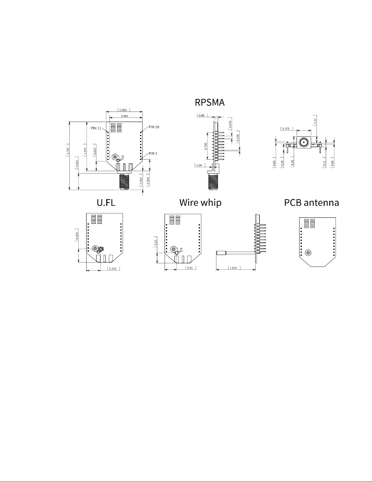
Mechanical drawings
The following figures show the mechanical drawings for the XBee Wi-Fi RF Module. The drawings do
not show antenna options. All dimensions are in inches.
Through-hole device
XBee Wi-Fi RF Module User Guide
23
Page 24
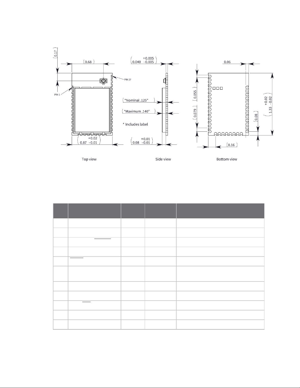
Hardware Pin signals
Surface-mount device
Pin signals
The following table describes the pin assignments for the through-hole device. A horizontal line above
the signal name indicates low-asserted signals.
Pin
# Name Direction
1 VCC - - Power supply
2 DIO13/DOUT Both Output UART data out
3
4 DIO12/SPI_MISO Both Disabled GPIO/ SPI slave out
5
6 DIO10/RSSI
7 DIO11/PWM1 Both Disabled GPIO
8 Reserved - - Do not connect
9
10 GND - - Ground
DIO14/DIN/CONFIG
RESET
PWM/PWM0
DIO8/DTR/SLEEP_RQ
Default
state Description
Both Input UART data In
Input Input Device reset
Both Output RX signal strength indicator/GPIO
Both Input Pin sleep control line /GPIO
11 DIO4/SPI_MOSI Both Disabled GPIO/SPI slave In
XBee Wi-Fi RF Module User Guide
24
Page 25

Hardware Pin signals
Pin
# Name Direction
12
13
14 VREF - - Not connected
15 DIO5/ASSOCIATE Both Output Associate indicator/GPIO
16
17
18 DIO2/AD2 /SPI_CLK Both Disabled Analog input/GPIO/SPI clock
19
20 DIO0/AD0/CB Both Disabled Analog Input/Commissioning
The following table describes the pin assignments for the surface-mount device. A horizontal line
above the signal name indicates low-asserted signals.
Pin
# Name Direction
DIO7/CTS
DIO9/ON_SLEEP
DIO6/RTS
DIO3/AD3 /SPI_SSEL
DIO1/AD1 /SPI_ATTN
Both Output Clear-to-send flow control/GPIO
Both Output Device status indicator/GPIO
Both Input Request-to-send flow control/GPIO
Both Disabled Analog input/GPIO/SPI slave select
Both Disabled Analog input/GPIO/SPI attention
Default
state Description
Button/GPIO
Default
state Description
1 GND - - Ground
2 VCC - - Power supply
3 DIO13/DOUT Both Output UART data out
4
5 DIO12 Both Disabled GPIO
6
7 DIO10/ RSSI
8 DIO11/PWM1 Both Disabled GPIO
9 Reserved - - Do not connect
10
11 GND - - Ground
12
13 GND - - Ground
14 DIO18/SPI_CLK Both Input GPIO/SPI clock
15
DIO14/DIN/CONFIG
RESET
PWM/PWM0
DIO8/DTR/SLEEP_RQ
DIO19/SPI_ATTN
DIO17/SPI_SSEL
Both Input UART data in
Input Input Device reset
Both Output RX signal strength indicator/GPIO
Both Input GPIO
Both Output GPIO/SPI attention
Both Input GPIO/SPI slave select
XBee Wi-Fi RF Module User Guide
25
Page 26

Hardware Design notes
Pin
# Name Direction
16 DIO16/SPI_SI Both Input GPIO/SPI slave in
17 DIO15/SPI_SO Both Output GPIO/SPI slave out
18 Reserved - - Do not connect
19 Reserved - - Do not connect
20 Reserved - - Do not connect
21 Reserved - - Do not connect
22 GND - - Ground
23 Reserved - - Do not connect
24 DIO4 Both Disabled GPIO
25
26
27 VREF - - Not connected
28 DIO5/ASSOC Both Output Associate indicator/GPIO
29
DIO7/CTS
DIO9/ON_SLEEP
DIO6/RTS
Both Output Clear-to-send flow control/ GPIO
Both Output Device status indicator/GPIO
Both Input Request-to-send flow control/ GPIO
Default
state Description
30 DIO3/AD3 Both Disabled Analog input/GPIO
31 DIO2/AD2 Both Disabled Analog input/GPIO
32 DIO1/AD1 Both Disabled Analog input/GPIO
33 DIO0/AD0/CB Both Disabled Analog input/Commissioning
34 Reserved - - Do not connect
35 GND - - Ground
36 RF Both - RF I/O for RF pad variant
37 Reserved - - Do not connect
Design notes
The XBee devices do not specifically require any external circuitry specific connections for proper
operation. However, there are some general design guidelines that we recommend for help in
troubleshooting and building a robust design.
Power supply
A poor power supply can lead to poor device performance, especially if you do not keep the supply
voltage within tolerance or if it is excessively noisy. To help reduce noise, place a 1.0 μF and 8.2 pF
capacitor as near as possible to pin 1 on the PCB. If you are using a switching regulator for the power
Button/GPIO
XBee Wi-Fi RF Module User Guide
26
Page 27

Hardware Design notes
supply, switch the frequencies above 500 kHz. Limit the power supply ripple to a maximum 50 mV
peak to peak.
Pin connection recommendations
The only required pin connections are VCC, GND, and either DOUT and DIN or SPI_CLK, SPI_SSEL, SPI_
MOSI, and SPI MISO. To support serial firmware updates, you should connect VCC, GND, DOUT, DIN,
RTS, and DTR.
Leave all unused pins disconnected. Use the PRcommand to pull all of the inputs on the device high
using 40 k internal pull-up resistors. You do not need a specific treatment for unused outputs.
For applications that need to ensure the lowest sleep current, never leave inputs floating. Use internal
or external pull-up or pull-down resistors, or set the unused I/O lines to outputs. You can achieve the
deep sleep (pin sleep) current specification using a standard XBee Interface Board with the XBee Wi-Fi
RF Module's pull-up and pull-down resistors configured as default.
You can connect other pins to external circuitry for convenience of operation. For example, the
Associate signal (TH pin 15/SMT pin 28) and the ON_SLEEP signal (TH pin 13/SMT pin 26) will change
level or behavior based on the state of the device.
Board layout
When designing the host PCB, account for the device dimensions shown in Mechanical drawings. See
Manufacturing information for the recommended footprints and required keepout areas. Use good
design practices when connecting power and ground, making those traces wide enough to
comfortably support the maximum currents or using planes if possible.
Antenna performance
Antenna location is important for optimal performance. The following suggestions help you achieve
optimal antenna performance. Point the antenna up vertically (upright). Antennas radiate and receive
the best signal perpendicular to the direction they point, so a vertical antenna's omnidirectional
radiation pattern is strongest across the horizon.
Position the antennas away from metal objects whenever possible. Metal objects between the
transmitter and receiver can block the radiation path or reduce the transmission distance. Objects
that are often overlooked include:
n metal poles
n metal studs
n structure beams
n concrete, which is usually reinforced with metal rods
If you place the device inside a metal enclosure, use an external antenna. Common objects that have
metal enclosures include:
n vehicles
n elevators
n ventilation ducts
n refrigerators
n microwave ovens
XBee Wi-Fi RF Module User Guide
27
Page 28

Hardware Design notes
n batteries
n tall electrolytic capacitors
Do not place XBee devices with the chip or integrated PCB antenna inside a metal enclosure.
Do not place any ground planes or metal objects above or below the antenna.
For the best results, mount the device at the edge of the host PCB. Ensure that the ground, power,
and signal planes are vacant immediately below the antenna section.
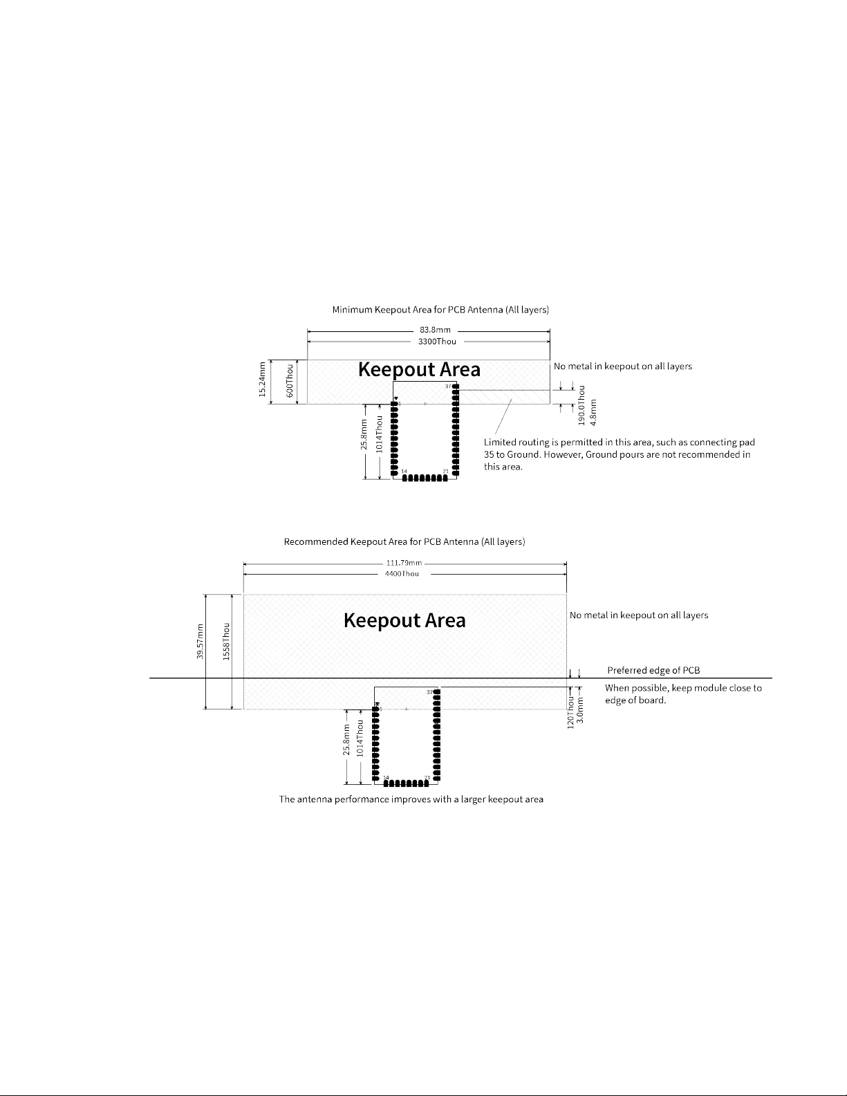
Keepout area
The following drawings show important recommendations for designing with the PCB antenna device
using the through-hole and surface-mount devices. Do not mount the surface-mount PCB antenna
device on the RF Pad footprint because that footprint requires a ground plane within the keepout
area.
Through-hole keepout
XBee Wi-Fi RF Module User Guide
28
Page 29
Hardware Design notes
Notes
1. We recommend non-metal enclosures. For metal enclosures, use an external antenna.
2. Keep metal chassis or mounting structures in the keepout area at least 2.54 cm (1 in) from the
antenna.
3. Maximize the distance between the antenna and metal objects that might be mounted in the
keepout area.
4. These keepout area guidelines do not apply for wire whip antennas or external RFconnectors.
Wire whip antennas radiate best over the center of a ground plane.
Surface-mount keepout
Notes
1. We recommend non-metal enclosures. For metal enclosures, use an external antenna.
2. Keep metal chassis or mounting structures in the keepout area at least 2.54 cm (1 in) from the
antenna.
3. Maximize the distance between the antenna and metal objects that might be mounted in the
keepout area.
XBee Wi-Fi RF Module User Guide
29
Page 30

Hardware Design notes for RF pad devices
4. These keepout area guidelines do not apply for wire whip antennas or external RFconnectors.
Wire whip antennas radiate best over the center of a ground plane.
Design notes for RF pad devices
The RF pad is a soldered antenna connection. The RF signal travels from pin 33 the RF pad connection
(pad 33 on micro modules and pad 36 on surface-mount modules) on the device to the antenna
through an RF trace transmission line on the PCB. Any additional components between the device and
antenna violates modular certification. The controlled impedance for the RF trace is 50 Ω.
We recommend using a microstrip trace, although you can also use a coplanar waveguide if you need
more isolation. A microstrip generally requires less area on the PCB than a coplanar waveguide. We do
not recommend using a stripline because sending the signal to different PCB layers can introduce
matching and performance problems.
Following good design practices is essential when implementing the RF trace on a PCB. Consider the
following points:
n Minimize the length of the trace by placing the RPSMA jack close to the device.
n Connect all of the grounds on the jack and the device to the ground planes directly or through
closely placed vias.
n Space any ground fill on the top layer at least twice the distance d (in this case, at least 0.028")
from the microstrip to minimize their interaction.
Additional considerations:
n The top two layers of the PCB have a controlled thickness dielectric material in between.
n The second layer has a ground plane which runs underneath the entire RF pad area. This
ground plane is a distance d, the thickness of the dielectric, below the top layer.
n The top layer has an RF trace running from pin 33 of the device to the RF pin of the RPSMA
connector.
n The RF trace width determines the impedance of the transmission line with relation to the
ground plane. Many online tools can estimate this value, although you should consult the PCB
manufacturer for the exact width.
Implementing these design suggestions helps ensure that the RF pad device performs to its
specifications.
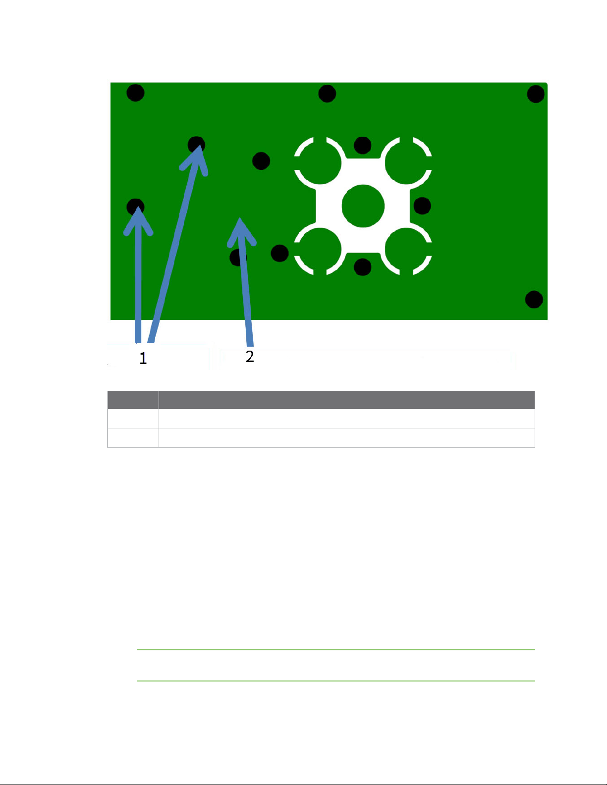
The following figures show a layout example of a host PCB that connects an RF pad device to a right
angle, through-hole RPSMA jack.
XBee Wi-Fi RF Module User Guide
30
Page 31

Hardware Design notes for RF pad devices
Number Description
1
2 Device pin 33.
2 RF pad pin.
3 50 Ω microstrip trace.
4 RF connection of RPSMA jack.
The width in this example is approximately 0.025 in for a 50 Ω trace, assuming d = 0.014 in, and that
the dielectric has a relative permittivity of 4.4. This trace width is a good fit with the device footprint's
0.335" pad width.
Note We do not recommend using a trace wider than the pad width, and using a very narrow trace
(under 0.010") can cause unwanted RF loss.
The following illustration shows PCB layer 2 of an example RF layout.
Maintain a distance of at least 2 d between microstrip and ground fill.
XBee Wi-Fi RF Module User Guide
31
Page 32
Hardware Mounting considerations
Number Description
1
Use multiple vias to help eliminate ground variations.
2 Put a solid ground plane under RF trace to achieve the desired impedance.
Mounting considerations
We design the through-hole device to mount into a receptacle so that you do not have to solder the
device when you mount it to a board. The interface boards provided in the XBee Wi-Fi Development Kit
has two ten-pin receptacles for connecting the device.
Century Interconnect manufactures the receptacles used on Digi development boards. Several other
manufacturers provide comparable mounting solutions; however, Digi currently uses the following
receptacles:
n Through-hole single-row receptacles: Samtec part number: MMS-110-01-L-SV (or equivalent)
n Through-hole single-row receptacles: Mill-Max part number: 831-43-0101-10-001000
n Surface-mount double-row receptacles: Century Interconnect part number: CPRMSL20-D-0-1
(or equivalent)
n Surface-mount single-row receptacles: Samtec part number: SMM-110-02-SM-S
Note We recommend that you print an outline of the device on the board to indicate the
correct orientation for mounting the device.
XBee Wi-Fi RF Module User Guide
32
Page 33

Operation
Serial interface 34
UART data flow 34
Serial data 34
SPI communications 35
Serial buffers 36
UART flow control 37
The Commissioning Button 38
Connection indicators 39
Perform a serial firmware update 40
XBee Wi-Fi RF Module User Guide
33
Page 34
Operation Serial interface
Serial interface
The XBee Wi-Fi RF Module interfaces to a host device through a serial port. The device's serial port can
communicate:
n Through a logic and voltage compatible universal asynchronous receiver/transmitter (UART).
n Through a level translator to any serial device, for example, through an RS-232 or USB
interface board.
n Through a serial peripheral interface (SPI) port.
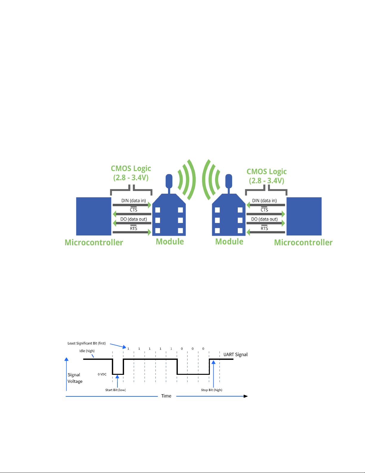
UART data flow
Devices that have a UART interface connect directly to the pins of the XBee Wi-Fi RF Module as shown
in the following figure. The figure shows system data flow in a UART-interfaced environment. Lowasserted signals have a horizontal line over the signal name.
Serial data
A device sends data to the XBee Wi-Fi RF Module's UART through TH pin 3/SMT pin 4 DIN as an
asynchronous serial signal. When the device is not transmitting data, the signals should idle high.
For serial communication to occur, you must configure the UART of both devices (the microcontroller
and the XBee Wi-Fi RF Module) with compatible settings for the baud rate, parity, start bits, stop bits,
and data bits.
Each data byte consists of a start bit (low), 8 data bits (least significant bit first) and a stop bit (high).
The following diagram illustrates the serial bit pattern of data passing through the device. The
diagram shows UART data packet 0x1F (decimal number 31) as transmitted through the device.
You can configure the UART baud rate, parity, and stop bits settings on the device with the BD, NB,
and SB commands respectively. For more information, see Serial interfacing commands.
XBee Wi-Fi RF Module User Guide
34
Page 35
Operation SPI communications
In the rare case that a device has been configured with the UART disabled, you can recover the device
to UART operation by holding DIN low at reset time. DIN forces a default configuration on the UART at
9600 baud and it brings the device up in Command mode on the UART port. You can then send the
appropriate commands to the device to configure it for UART operation. If those parameters are
written, the device comes up with the UART enabled on the next reset.
SPI communications
The XBee Wi-Fi RF Module supports SPI communications in slave mode. Slave mode receives the clock
signal and data from the master and returns data to the master. The following table shows the
signals that the SPI port uses on the device.
Signal Function
SPI_MOSI
Inputs serial data from the master
(MasterOut,SlaveIn)
SPI_MISO(Master
Outputs serial data to the master
In,Slave Out)
SPI_SCLK
Clocks data transfers on MOSI and MISO
(SerialClock)
SPI_SSEL
Enables serial communication with the slave
(SlaveSelect)
SPI_ATTN (Attention) Alerts the master that slave has data queued to send. The XBee Wi-Fi RF
Module asserts this pin as soon as data is available to send to the SPI
master and it remains asserted until the SPI master has clocked out all
available data.
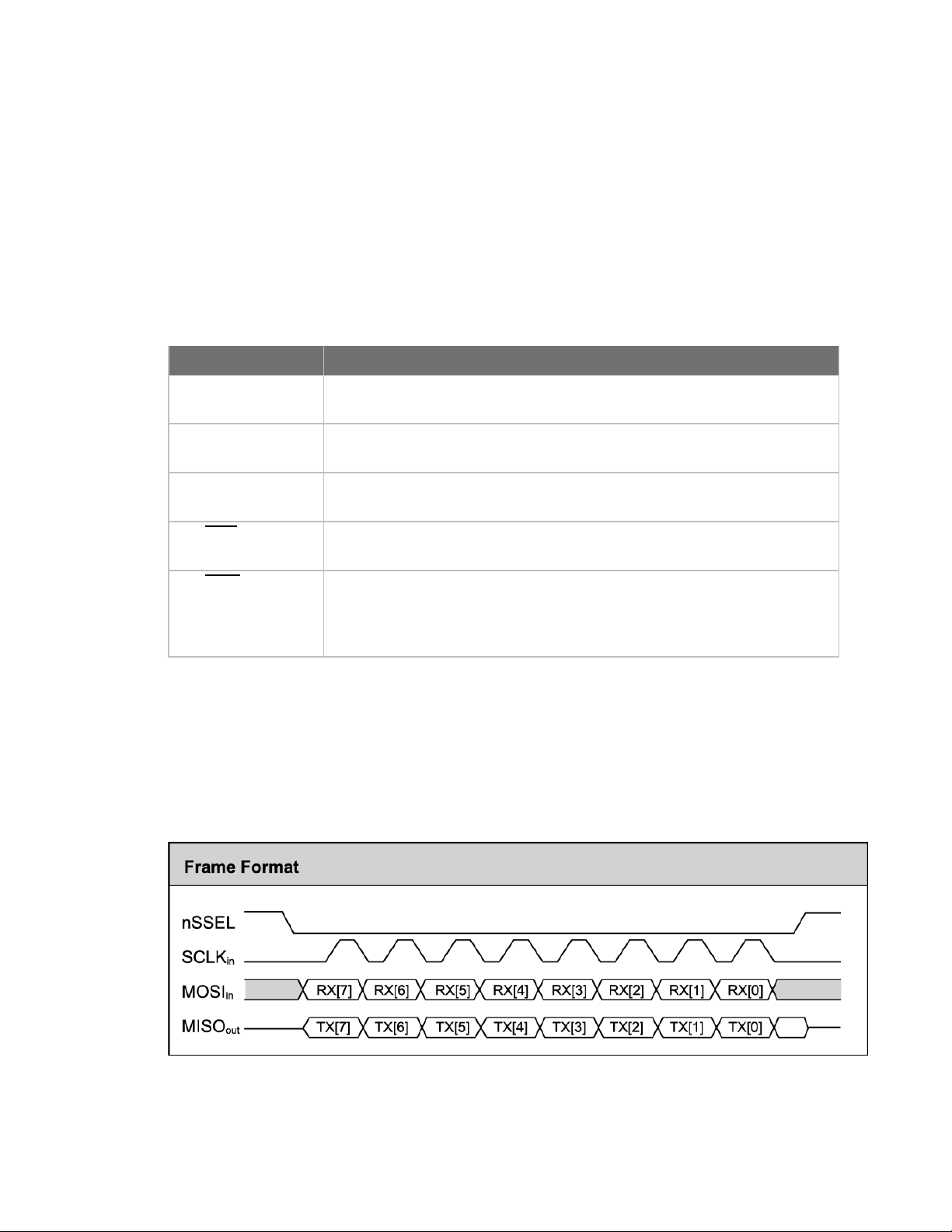
In this mode:
n Data is most significant bit (MSB) first; bit 7 is the first bit of a byte sent over the interface.
n Frame Format mode 0 is used. This means CPOL= 0 (idle clock is low) and CPHA = 0 (data is
sampled on the clock’s leading edge).
n The SPI port only supports API Mode (AP = 1).
The following diagram shows the frame format mode 0 for SPI communications.
SPI mode is chip to chip communication. We do not supply a SPI communication option on the device
development evaluation boards.
XBee Wi-Fi RF Module User Guide
35
Page 36

Operation Serial buffers
Select the SPI port
On the through-hole devices, you can force SPI mode by holding DOUT/DIO13 low while resetting the
device until SPI_ATTN asserts. This causes the device to disable the UART and go straight into SPI
communication mode. Once configuration is complete, the device queues a modem status frame to
the SPI port, which causes the SPI_ATTN line to assert. The host can use this to determine that the
SPI port is configured properly. This method forces the configuration to provide full SPI support for the
following parameters:
n D1 (This parameter will only be changed if it is at a default of zero when the method is
invoked.)
n D2
n D3
n D4
n P2
As long as the host does not issue a WR command, these configuration values revert to previous
values after a power-on reset. If the host issues a WR command while in SPI mode, these same
parameters are written to flash. After a reset, parameters that were forced and then written to flash
become the mode of operation.
If the UART is disabled and the SPI is enabled in the written configuration, then the device comes up in
SPI mode without forcing it by holding DOUT low. If both the UART and the SPI are enabled at the time
of reset, then output goes to the UART until the host sends the first input. If that first input comes on
the SPI port, then all subsequent output goes to the SPI port and the UART is disabled. If the first
input comes on the UART, then all subsequent output goes to the UART and the SPI is disabled.
Once you select a serial port (UART or SPI), all subsequent output goes to that port, even if you apply a
new configuration. The only way to switch the selected serial port is to reset the device. On surfacemount devices, forcing DOUT low at the time of reset has no effect. To use SPI mode on the SMT
devices, assert the SPI_SSEL (TH pin 17/SMT pin 15) low after reset and before any UART data is input.
When the master asserts the slave select (SPI_SSEL) signal, SPI transmit data is driven to the output
pin SPI_MISO, and SPI data is received from the input pin SPI_MOSI. The SPI_SSEL pin has to be
asserted to enable the transmit serializer to drive data to the output signal SPI_MISO. A rising edge
on SPI_SSEL causes the SPI_MISO line to be tri-stated such that another slave device can drive it, if so
desired.
If the output buffer is empty, the SPI serializer transmits the last valid bit repeatedly, which may be
either high or low. Otherwise, the device formats all output in API mode 1 format, as described in
Operate in API mode. The attached host is expected to ignore all data that is not part of a formatted
API frame.
Serial buffers
The XBee Wi-Fi RF Module maintains internal buffers to collect serial and RF data that it receives. The
serial receive buffer collects incoming serial characters and holds them until the device can process
them. The serial transmit buffer collects the data it receives via the RF link until it transmits that data
out the UART or SPI port. The following figure shows the process of device buffers collecting received
serial data.
XBee Wi-Fi RF Module User Guide
36
Page 37

Operation UART flow control
Serial receive buffer
When serial data enters the device through the DIN pin (or the MOSI pin), it stores the data in the
serial receive buffer until the device can process it. Under certain conditions, the device may not be
able to process data in the serial receive buffer immediately. If large amounts of serial data are sent
to the device such that the serial receive buffer would overflow, then it discards new data. If the UART
is in use, you can avoid this by the host side honoring CTS flow control.
Serial transmit buffer
When the device receives RF data, it moves the data into the serial transmit buffer and sends it out
the UART or SPI port. If the serial transmit buffer becomes full and the system buffers are also full,
then it drops the entire RF data packet. Whenever the device receives data faster than it can process
and transmit the data out the serial port, there is a potential of dropping data, even in TCP mode.
UART flow control
You can use the RTS and CTS pins to provide RTS and/or CTS flow control. CTS flow control provides an
indication to the host to stop sending serial data to the device. RTS flow control allows the host to
signal the device to not send data in the serial transmit buffer out the UART. To enable RTS/CTS flow
control, use the D6 and D7 commands.
Note Serial port flow control is not possible when using the SPI port.
CTS flow control
The FT command allows you to specify how many bytes of data can be queued up in the serial
transmit buffer before the device asserts CTS low. The serial receive buffer can hold up the 2100
bytes, but FT cannot be set any larger than 2083 bytes, leaving 17 bytes that can be sent by the host
before the data is dropped.
By default, FT is 2035 (0x7F3), which allows the host to send 65 bytes to the device after the device
asserts CTS before the data is dropped. In either case, CTS is not re-asserted until the serial receive
buffer has FT-17 or less bytes in use.
RTS flow control
If you send D6 (DIO6 Configuration) to enable RTS flow control, the device does not send data in the
serial transmit buffer out the DOUT pin as long as RTS is de-asserted (set high). Do not de-assert RTS
XBee Wi-Fi RF Module User Guide
37
Page 38
Operation The Commissioning Button
for long periods of time or the serial transmit buffer will fill. If the device receives an RF data packet
and the serial transmit buffer does not have enough space for all of the data bytes, it discards the
entire RF data packet.
If the device sends data out the UART when RTS is de-asserted (set high) the device could send up to
four characters out the UART port after RTS is de-asserted. This means your application needs to deassert RTS by the time its receive capacity is within 4 bytes of full.
The Commissioning Button
The XBee Wi-Fi RF Module supports a set of commissioning and LED functions to help you deploy and
commission devices. These functions include the Commissioning Button definitions and the associated
LED functions.
To enable the Commissioning Button functionality on TH pin 20/SMT pin 33, set DO (Device Options) to
1. The functionality is enabled by default.
Use the CB command to simulate button presses in software. Send CB with a parameter set to the
number of button presses to perform. For example, if you send CB2, the device performs the action(s)
associated with two button presses, CB4 is four button presses. See CB (Commissioning Button).
It provides two different services:
n Two button presses in fast sequence invoke WPS; see Wi-Fi Protected Setup (WPS).
n Four button presses in fast sequence force the device into Soft AP Provisioning mode by
clearing the SSID and security parameters. It also ensures that Soft AP mode is enabled. After
the four button presses clear the security parameters, they are NOT written. Send a separate
WR (Write), if desired.
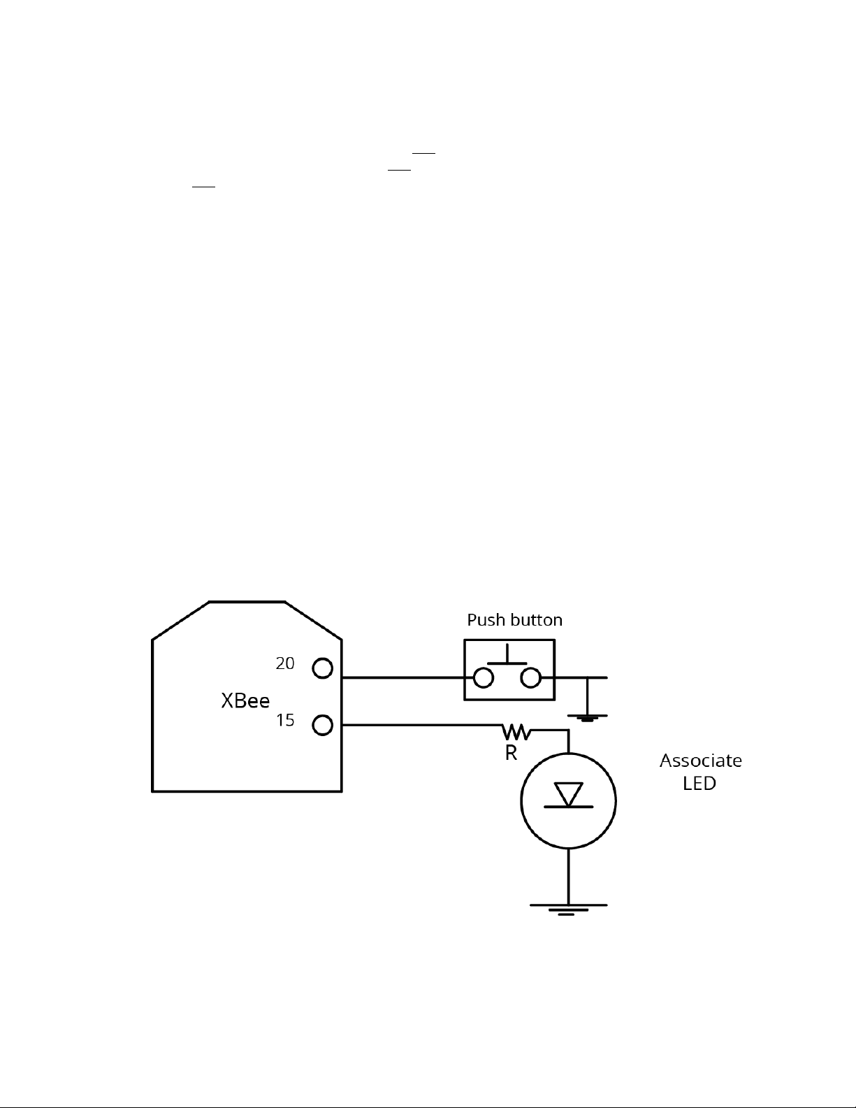
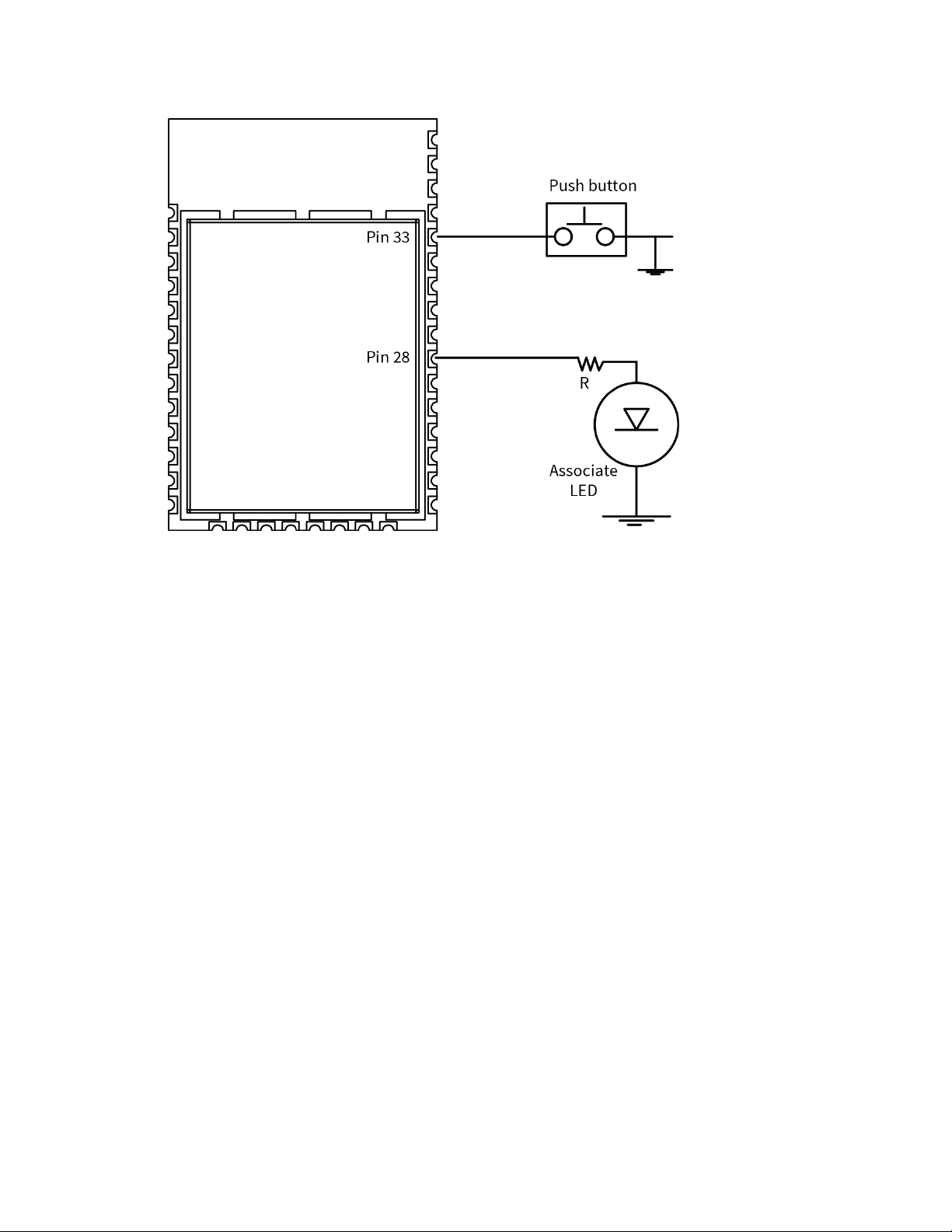
The following features can be supported in hardware. Connect a pushbutton and an LED to XBee Wi-Fi
RF Module pins 33 and 28 (SMT), or pins 20 and 15 (TH) respectively to support Commissioning Button
definitions and the associated LED functions.
XBee Wi-Fi RF Module User Guide
38
Page 39
Operation Connection indicators
Connection indicators
There are four connection indicators in this software:
n AI (Association Indication)
n The Associate LED
n TCP connection indicator
n Remote Manager connection indicator
The Associate LED
The Associate pin (TH pin 15/SMT pin 28) provides an indication of when the device associates with an
access point (AP). To take advantage of these indications, connect an LED to the Associate pin.
To enable the Associate LED functionality, set D5 (DIO5 Configuration) to 1; it is enabled by default. If
enabled, the Associate pin is configured as an output.
Use LT (Associate LED Blink Time) to override the blink rate of the Associate pin. If you set LT to 0, the
device uses the default blink time: 250 ms.
TCP connection indicator
In Transparent mode, only one TCP connection is allowed and you can configure DIO12 (also known as
CD) to indicate whether or not that TCP socket is connected. To enable DIO12, set P2 (DIO12
Configuration) to 6. When so configured, DIO12 outputs a low signal when the TCP socket is connected
and it outputs a high signal when the TCP socket is disconnected. The high signal remains when
operating in UDP mode because there is no TCP connection.
XBee Wi-Fi RF Module User Guide
39
Page 40

Operation Perform a serial firmware update
Remote Manager connection indicator
AI (Association Indication) and the Associate LED indicate when the device is fully associated with the
access point (AP), but there is another level of connectivity provided by DI (Remote Manager Indicator)
that tells whether or not the TCP socket to Digi Remote Manager is connected. The values defined for
DI are:
n 0 = Connected to Remote Manager
n 1 = Configured, but not yet associated to AP
n 2 = Associated to AP, but not yet connected to Remote Manager
n 3 = Disconnecting from Remote Manager
n 4 = Not configured to connect to Remote Manager
When DI is either 2 or 3, the Associate LED has a different blink pattern that looks like this:
Where the low signal means LED off and the high signal means LED on.
The normal association LED signal alternates evenly between high and low as shown below:
Perform a serial firmware update
Serial firmware updates use the XBee bootloader which ships in all devices. This bootloader allows you
to update the firmware. Normally, the running application can be told to invoke the bootloader
through a command from XCTU. If that command is not available in the currently loaded firmware, the
bootloader includes a modified entry mechanism using pins TH pin 3/SMT pin 4, TH pin 9/SMT pin 10,
and TH pin 16/SMT pin 29 (DIN, DTR, and RTS, respectively).
To force the XBee bootloader to run and load a new version of the firmware, at the time the device is
reset:
1. Drive DIN low.
2. Drive DTR low.
3. Drive RTS high.
This method works even when the current firmware version does not support the firmware update
feature. XCTU can update firmware on the XBee Wi-Fi RF Module over the UART port, but not over the
SPI port. Contact Digi support for details.
XBee Wi-Fi RF Module User Guide
40
Page 41

Modes
Serial modes 42
Modes of operation 47
Sleep modes 49
Soft AP mode 49
XBee Wi-Fi RF Module User Guide
41
Page 42

Modes Serial modes
Serial modes
The firmware operates in several different modes. Two top-level modes establish how the device
communicates with other devices through its serial interface: Transparent operating mode and API
operating mode. Use the AP command to choose Serial mode. XBee Wi-Fi RF Modules use Transparent
operation as the default serial mode.
The following modes describe how the serial port sends and receives data.
Transparent operating mode
Devices operate in this mode by default. The device acts as a serial line replacement when it is in
Transparent operating mode. The device queues all UART data it receives through the DIN pin for RF
transmission. When a device receives RF data, it sends the data out through the DOUT pin. You can set
the configuration parameters using Command mode.
Note Transparent operating mode is not available when using the SPI interface; see SPI
communications.
Serial-to-RF packetization
The device buffers data in the serial receive buffer until one of the following causes the data to be
packetized and transmitted:
n The device receives no serial characters for the amount of time determined by the RO
(Packetization Timeout) parameter. If RO = 0, packetization begins when a character is
received. If RO is non-zero, the data is packetized after RO character times of no transitions on
the DIN pin. However, if the time required for RO characters is less than 100 microseconds,
then DIN must still be idle for at least 100 microseconds, which is the minimal idle time
required for packetizing packets at any baud rate.
n The device receives the Command Mode Sequence (GT + CC + GT). Any character buffered in
the serial receive buffer before the sequence is transmitted.
n The device receives the maximum number of characters that fits in an RF packet (100 bytes).
API operating mode
Application programming interface (API) operating mode is an alternative to Transparent mode. It is
helpful in managing larger networks and is more appropriate for performing tasks such as collecting
data from multiple locations or controlling multiple devices remotely. API mode is a frame-based
protocol that allows you to direct data on a packet basis. It can be particularly useful in large
networks where you need control over the operation of the radio network or when you need to know
which node a data packet is from. The device communicates UART or SPI data in packets, also known
as API frames. This mode allows for structured communications with serial devices.
The application programming interface (API) provides alternative means of configuring devices and
routing data at the host application layer. A host application can send data frames to the device that
contain address and payload information instead of using Command mode to modify addresses. The
device sends data frames to the application containing status packets, as well as source and payload
information from received data packets.
For more information, see API mode overview.
XBee Wi-Fi RF Module User Guide
42
Page 43

Modes Serial modes
Comparing Transparent and API modes
The XBee Wi-Fi RF Module can use its serial connection in two ways:Transparent mode or API
operating mode. You can use a mixture of devices running API mode and transparent mode in a
network.
The following table compares the advantages of transparent and API modes of operation:
Feature Description
Transparent mode features
Simple interface All received serial data is transmitted unless the device is in Command
mode
Easy to support It is easier for an application to support Transparent operation and
Command mode
API mode features
Easy to manage data
transmissions to
multiple destinations
Transmitting RF data to multiple remote devices only requires the
application to change the address in the API frame. This process is much
faster than in Transparent mode where the application must enter
Command mode, change the address, exit Command mode, and then
transmit data.
Each API transmission
can return a transmit
status frame indicating
Because acknowledgments are sent out of the serial interface, this
provides more information about the health of the RF network and can
be used to debug issues after the network has been deployed.
the success or reason
for failure
Received data frames
All received RF data API frames indicate the source address
indicate the sender's
address
Advanced addressing
support
Advanced networking
diagnostics
API transmit and receive frames can expose addressing fields including
source and destination endpoints, cluster ID, and profile ID
API frames can provide indication of I/O samples from remote devices,
and node identification messages.
Some network diagnostic tools such as
Trace Route, NACK, and Link Testing can only be performed in API mode.
Remote Configuration Set/read configuration commands can be sent to remote devices to
configure them as needed using the API
We recommend API mode when a device:
n Sends RF data to multiple destinations
n Sends remote configuration commands to manage devices in the network
n Receives RF data packets from multiple devices, and the application needs to know which
device sent which packet
API mode is required when:
XBee Wi-Fi RF Module User Guide
43
Page 44

Modes Serial modes
n Receiving I/O samples from remote devices
n Using SPI for the serial port
n Sends RF data to multiple destinations
n Sends remote configuration commands to manage devices in the network
n Receives IO samples from remote devices
n Receives RF data packets from multiple devices, and the application needs to know which
device sent which packet
n Needs to use the send data request and device request features of Remote Manager
If the conditions listed above do not apply (for example, a sensor node, router, or a simple application),
then Transparent operation might be suitable. It is acceptable to use a mixture of devices running API
mode and Transparent mode in a network.
The following table provides a comparison of the two modes.
Transparent operating mode API operating mode
When to use:
n The conditions for using API mode
do not apply.
Advantages:
n Provides a simple interface.
n It is easy for an application to
support; what you send is exactly
what other devices get, and vice
versa.
n Works very well for two-way
communication between XBee
devices.
When to use:
n The device sends wireless data to multiple
destinations.
n The device configures remote devices in the
network.
n The device receives wireless data packets from
multiple XBee devices, and the application needs
to identify which devices send each packet.
n The device receives I/O samples from remote
XBee devices.
Advantages:
n You can set or read the configuration of remote
XBee devices in the network.
n You can transmit data to one or multiple
destinations; this is much faster than
Transparent mode where the configuration must
be updated to establish a new destination.
n Received data includes the sender's address.
n Received data includes transmission details and
reasons for success or failure.
n This mode has several advanced features, such
as advanced networking diagnostics, and
firmware updates.
XBee Wi-Fi RF Module User Guide
44
Page 45

Modes Serial modes
Transparent operating mode API operating mode
Disadvantages:
n You cannot set or read the
configuration of remote XBee
devices in the network.
n You must first update the
configuration to establish a new
destination and transmit data.
n You cannot identify the source of
received data, as it does not
include the sender's address.
n Received data does not include
Disadvantages:
n The interface is more complex; data is structured
in packets with a specific format.
n This mode is more difficult to support;
transmissions are structured in packets that
need to be parsed (to get data) or created (to
transmit data).
n Sent data and received data are not identical;
received packets include some control data and
XTend vB information.
transmission details or the
reasons for success or failure.
n This mode does not offer the
advanced features of API mode,
including advanced networking
diagnostics, and firmware
updates.
Command mode
Command mode is a state in which the firmware interprets incoming characters as commands. It
allows you to modify the device’s configuration using parameters you can set using AT
commands.When you want to read or set any parameter of the XBee Wi-Fi RF Module using this mode,
you have to send an AT command.Every AT command starts with the lettersATfollowed by the two
characters that identify the command and then by some optional configuration values.
The operating modes of the XBee Wi-Fi RF Module are controlled by the AP (API Enable) setting,
butCommand mode is always available as a mode thedevice can enter while configured for any of the
operating modes.
Command mode is available on the UART interface for all operating modes. You cannot use the SPI
interface to enter Command mode.
Enter Command mode
To get a device to switch into Command mode, you must issue the following sequence:+++within one
second. There must be at least one second preceding and following the+++sequence. Both the
command character (CC) and the silence before and after the sequence (GT) are configurable. When
the entrance criteria are met the device responds with OK\r on UART signifying that it has entered
Command mode successfully and is ready to start processing AT commands.
If configured to operate in Transparent operating mode, when entering Command mode the XBee WiFi RF Module knows to stop sending data and start accepting commands locally.
Note Do not press Return or Enter after typing+++because it interrupts the guard time silence and
prevents you from entering Command mode.
When the device is in Command mode, it listens for user input and is able to receive AT commands on
the UART. IfCTtime (default is 10 seconds) passes without any user input, the device drops out of
XBee Wi-Fi RF Module User Guide
45
Page 46

Modes Serial modes
Command mode and returns to the previous operating mode. You can force the device to leave
Command mode by sending CN (Exit Command Mode).
You can customize the command character, the guard times and the timeout in the device’s
configuration settings. For more information, seeCC (Command Mode Character),CT (Command
Mode Timeout)andGT (Gaurd Times).
Troubleshooting
Failure to enter Command mode is often due to baud rate mismatch. Ensure that the baud rate of the
connection matches the baud rate of the device. By default, BD (Baud Rate) = 3 (9600 b/s).
There are two alternative ways to enter Command mode:
n A serial break for six seconds enters Command mode. You can issue the "break" command
from a serial console, it is often a button or menu item.
n Asserting DIN (serial break) upon power up or reset enters Command mode. XCTU guides you
through a reset and automatically issues the break when needed.
Both of these methods temporarily set the device's baud rate to 9600 and return anOKon the UART
to indicate that Command mode is active. When Command mode exits, the device returns to normal
operation at the baud rate that BDis set to.
Send AT commands
Once the device enters Command mode, use the syntax in the following figure to send AT commands.
Every AT command starts with the lettersAT, which stands for "attention." TheATis followed by two
characters that indicate which command is being issued, then by some optional configuration values.
To read a parameter value stored in the device’s register, omit the parameter field.
Multiple AT commands
You can send multiple AT commands at a time when they are separated by a comma in Command
mode; for example,ATNIMy XBee,AC<cr>.
The preceding example changes theNI (Node Identifier) to My XBeeand makes the setting active
through AC (Apply Changes).
Parameter format
Refer to the list of AT commands for the format of individual AT command parameters. Valid formats
for hexidecimal values include with or without a leading0xfor exampleFFFFor0xFFFF.
Response to AT commands
When using AT commands to set parameters the XBee Wi-Fi RF Module responds with OK<cr> if
successful and ERROR<cr> if not.
XBee Wi-Fi RF Module User Guide
46
Page 47

Modes Modes of operation
Apply command changes
Any changes you make to the configuration command registers using AT commands do not take effect
until you apply the changes. For example, if you send theBDcommand to change the baud rate, the
actual baud rate does not change until you apply the changes. To apply changes:
1. Send AC (Apply Changes).
2. Send WR (Write).
or:
3. Exit Command mode.
Make command changes permanent
Send a WR (Write) command to save the changes. WR writes parameter values to non-volatile memory
so that parameter modifications persist through subsequent resets.
Send as RE (Restore Defaults) to wipe settings saved using WR back to their factory defaults.
Note You still have to use WR to save the changes enacted with RE.
Exit Command mode
1. Send CN (Exit Command Mode) followed by a carriage return.
or:
2. If the device does not receive any valid AT commands within the time specified byCT
(Command Mode Timeout), it returns to Transparent or API mode. The default Command mode
timeout is10seconds.
For an example of programming the device using AT Commands and descriptions of each configurable
parameter, see AT commands.
Modes of operation
Idle mode
When not receiving or transmitting data, the device is in Idle mode. During Idle mode, the device
listens for valid data on both the RF and serial ports.
The device shifts into the other modes of operation under the following conditions:
n Transmit mode (serial data in the serial receive buffer is ready to be packetized).
n Receive mode (valid RF data received through the antenna).
n Sleep mode (Sleep mode condition is met).
n Command mode (Command mode sequence issued).
Transmit mode
When the device receives serial data and is ready to packetize it, the device attempts to transmit the
serial data. The destination address determines which node(s) will receive and send the data.
XBee Wi-Fi RF Module User Guide
47
Page 48

Modes Modes of operation
Receive mode
This is the default mode for the XBee Wi-Fi RF Module. The device is in Receive mode when it is not
transmitting data. If a destination node receives a valid RF packet, the destination node transfers the
data to its serial transmit buffer.
Configuration mode
You may not always know the parameters that the XBee Wi-Fi RF Module is configured with. If those
parameters affect how the XBee Wi-Fi RF Module enters Command mode, and if the parameters were
previously written to non-volatile memory, then Command mode is not available to either read the
parameters or to set them to known values. This makes configuring the device difficult unless you can
successfully guess the configuration to allow it to enter Command mode.
An example of this problem is when the UART baud rate is unknown. In this case, the +++ sequence to
enter Command mode is not recognized due to a baud rate mismatch, preventing the device from
entering Command mode.
Force the device to enter Configuration mode
To overcome the issue of unknown configuration parameters, you can force the XBee Wi-Fi RF Module
into Command mode with a known configuration as follows:
While holding DIN low (asserting the break key), reset the device.
Rather than coming up in Transparent mode, which is normal, it comes up in Command mode and
issues the OK prompt with the following default parameters applied for operation while in Command
mode:
Parameter setting Meaning
P3 = 1, P4 = 1
BD = 3
SB = 0
NB = 0
RO = 3
D6 = 0 No RTS flow control
D7 = 1 CTS flow control
FT 65 characters left in transmission buffer before CTS is turned off
CC = 0x2b + is used for Command mode character
GT = 0x3e8
CT = 0x64
If the XBee Wi-Fi RF Module exits Configuration mode without changing any parameter values, then all
parameters revert to their previous unknown state after it exits Command mode. Also, any values
that you query return the previously written settings rather than the temporarily applied default
settings described above.
UART enabled—only set for SPI-enabled devices
9600 baud rate
One stop bit
No parity
Three character times with no change on DIN before transmission
One second guard time
Ten second Command mode timeout
XBee Wi-Fi RF Module User Guide
48
Page 49

Modes Sleep modes
Recover from an unknown configuration
To recover from an unknown configuration to a known configuration, do the following:
1. Set up the interface to the XBee Wi-Fi RF Module to match the default configuration described
in Force the device to enter Configuration mode.
2. Press and hold DIN low while resetting the XBee Wi-Fi RF Module.
3. Release DIN (let it be pulled high) so the device can receive UART data.
4. At the OK prompt, enter the desired configuration settings. If desired, configuration settings
which were unknown may be read before setting them in this state.
5. Use the WR command to write the desired configuration to non-volatile memory.
6. Set up the interface to the XBee Wi-Fi RF Module to match the configuration just written to
non-volatile memory.
7. Optionally, reset the device and begin operation in the new mode.
Use XCTU to enter Configuration mode
XCTU is designed to support a forced configuration on a UART interface using the following
instructions. XCTU does not work directly over a SPI interface.
1. Connect an asynchronous serial port of the PC (either RS-232 or USB) to the development
board that the XBee Wi-Fi RF Module is plugged into.
2. Open XCTU.
3. To add your device to XCTU, see Add radio modules to XCTU in the XCTU User Guide.
4. The device(s) appear under the Radio Modules section on the left of the display.
5. To configure the settings, see Configure your modules in he XCTU User Guide.
6. When you are done entering the parameters, click the Write module settings button.
When the write is complete, all of the settings on the device are updated.
Click the Consoles working mode button on the toolbar and begin normal Transparent operation.
Sleep mode
Sleep modes allow the device to enter states of low power consumption when not in use. The XBee
Wi-Fi RF Module supports both pin sleep (Sleep mode entered on pin transition) and cyclic sleep
(device sleeps for a fixed time).
Sleep modes
Sleep modes allow the device to enter states of low power consumption when not in use. The XBee
Wi-Fi RF Module supports both pin sleep (sleep mode entered on pin transition) and cyclic sleep (device
sleeps for a fixed time). For both pin sleep and cyclic sleep the sleep level may be either deep sleep or
associated sleep. See Sleep modes for more information.
Soft AP mode
The XBee Wi-Fi RF Module can operate in Soft AP mode, also known as Wi-Fi Direct. In this mode the
XBee Wi-Fi RF Module emulates an access point (AP) rather than a station (STA). This allows another
Wi-Fi client device (STA) to connect to the XBee device directly without requiring a separate AP. WPA2
XBee Wi-Fi RF Module User Guide
49
Page 50

Modes Soft AP mode
security is available in Soft AP mode, but not WPA or WEP security. By default, Soft AP operates with
no security.
Enable Soft AP mode
The device operates in Soft AP mode in two different ways:
1. Provisioning mode
2. Pass through mode
You enable these two modes differently. To enable Pass through mode:
Set CE (Infrastructure Mode) to 1, which is not the default configuration. When CE is 1, it overrides
parameters for Provisioning mode.
Provisioning mode is enabled by default. To disable it:
Clear bit 1 of DO (Device Options).
To enable Provisioning mode, SSID must be NULL. SSID is NULL by default and you can force it to NULL
by issuing NR (Network Reset).
Station (STA) connection in Soft AP Provisioning mode
When the device operates in Soft AP Provisioning mode, it waits for a connection from a STA device.
Because the Service Set Identifier (SSID) is not configured, AI (Association Indication) is 0x23. The STA
device must:
n Support Wi-Fi
n Have an HTTP browser operating on TCP port 80
Examples of devices that might connect to the XBee Wi-Fi RF Module operating in Soft AP mode are
smart phones, tablets, and laptop computers.
The connecting STA device should scan for an AP. The XBee Wi-Fi RF Module advertises an SSID of:
xbee<MAC>
where <MAC> is the 6 byte MAC address of the XBee Wi-Fi RF Module formatted as follows:
xbee-XXXXXXXXXXXX
where each X represents a hex digit.
The STA needs to connect to that SSID, and then open a browser by entering 192.168.1.10 into the
address bar. This opens the webpage from the XBee Wi-Fi RF Module to allow you to configure it as
desired. The primary purpose of this webpage is to configure the XBee Wi-Fi RF Module to connect to
the desired access point with the desired security settings. The secondary purpose is to configure any
other parameters.
Use the webpage to configure a connected device
The webpage displays the current value of each configuration field.
1. Enter the desired parameters.
2. Click the Apply button at the bottom of the page.
The selected parameters are written to the non-volatile memory on the XBee Wi-Fi RF Module.
However, the network access parameters are only written if you enter a valid set of parameters. The
device tests the validity of those parameters by attempting to connect to the given access point.
XBee Wi-Fi RF Module User Guide
50
Page 51

Modes Soft AP mode
n The Soft AP webpage provides the same configuration options that are available in XCTU.
n The webpage is divided into sections that expand or collapse by clicking Show or Hide. The only
section expanded by default is the Network Access section.
n All fields proceeded with 0x must be hex values.
Note Do not programmatically configure the device in Soft AP mode because it is subject to change.
Station (STA) connection in Soft AP Pass Through mode
When the XBee Wi-Fi RF Module operates in Soft AP Pass Through mode, it does not use HTTP on port
80 and it operates the same as it would in STA mode with a few exceptions:
n Only one device may connect and the connecting device must be operating in STA mode.
n A TCP listening socket on the port specified by C0 (Serial Communication Service Port) is open
to accept connections, but no UDP listening socket is available.
n ID (SSID) specifies the SSID sent by the XBee Wi-Fi RF Module in the beacon, but if ID is NULL, it
advertises an SSID based on the device’s MAC address. For details, see Enable Soft AP mode.
n AI (Association Indication) is 0x23 while in Soft AP Provisioning mode (because ID is NULL), but
AI is 0 in Soft AP Pass Through mode as soon as the XBee Wi-Fi RF Module is ready to accept a
connection from a STA device. This is true whether or not ID is null.
XBee Wi-Fi RF Module User Guide
51
Page 52

Sleep modes
About sleep modes 53
Use the UARTSleep mode 53
Use SPI Sleep mode 53
AP Associated Sleep mode 54
Deep Sleep (Non-Associated Sleep) mode 54
Use sleep modes to sample data 55
XBee Wi-Fi RF Module User Guide
52
Page 53

Sleep modes About sleep modes
About sleep modes
The XBee Wi-Fi RF Module supports two different sleep modes:
n Pin Sleep
n Cyclic Sleep
In addition, you can modify the sleep mode current draw with the following sleep options:
n AP Associated Sleep
n Deep Sleep
Pin sleep allows an external microcontroller to determine when the XBee Wi-Fi RF Module should
sleep and when it should wake by using either the SLEEP_RQ pin (default) or the SPI_SSEL pin. In
contrast, cyclic sleep allows the sleep period and wake times to be configured using AT commands.
The device can stay associated to the access point or can enter a deeper sleep and associate to the
access point for each sleep/wake occurrence. The sleep mode is configurable with the SM and SO
commands.
Each of the sleep modes operate differently based on the serial interface (UART or SPI).
Use the UARTSleep mode
When the serial interface is UART, the ON_SLEEP pin is used to indicate that the device is entering
sleep mode, unless it is configured for a different usage. If you configure D9 (DIO9 Configuration) for
ON_SLEEP, then it is driven low when asleep and high when awake, whether using pin sleep or cyclic
sleep.
If you enable CTS hardware flow control with D7 (DIO7 Configuration), the CTS pin is de-asserted
(high) when entering sleep to indicate that serial data should not be sent to the device. The device will
not respond to serial or RF data when it is sleeping. Applications that use the UART are encouraged to
observe CTS flow control in any of the sleep modes. When the XBee Wi-Fi RF Module wakes from sleep
with flow control enabled, the CTS pin is asserted (low).
If using pin sleep, you must configure D8 (DIO8 Configuration) for SLEEP_RQ to put the device to sleep.
Otherwise, there is no sleep at all, meaning the device always stays awake in full power mode. When
you configure D8 for SLEEP_RQ, the host should drive SLEEP_RQ high to put the device to sleep, and
the host should drive SLEEP_RQ low to wake up the device.
Use SPI Sleep mode
When the serial interface is SPI, SPI_ATTN is used as an attention indicator to tell the SPI master
when it has data to send. Since SPI only operates in API mode, it asserts SPI_ATTN and sends out a
modem status indicator after initialization. The host can use this to know when the device is ready to
operate as a SPI slave. Since the function of SPI_ATTN is to indicate when the device has data to send
to the host, it may legitimately be driven high or low while the device is awake.
When using SPI, you can use either SLEEP_RQ or SPI_SSEL for pin sleep. If D8 (DIO8 Configuration) is
configured as a peripheral (1), then it is used for pin sleep. If not, and SPI_SSEL is configured as a
peripheral (which it must be to enable SPI operation), then SPI_SSEL is used for pin sleep.
Using SPI_SSEL for pin sleep has the advantage of requiring one less physical pin connection to
implement pin sleep on SPI. It has the disadvantage of putting the device to sleep whenever the SPI
master negates SPI_SSEL, even if that was not the intent. Therefore, if you can control SPI_SSEL,
whether or not data needs to be transmitted, then sharing the pin may be a good option. It makes the
SLEEP_RQ pin available for another purpose, or it simply requires one less pin to the SPI interface.
XBee Wi-Fi RF Module User Guide
53
Page 54

Sleep modes AP Associated Sleep mode
AP Associated Sleep mode
This option allows the device to sync up with beacons sent from the Access Point (AP) which contains
the Delivery Traffic Indication Message (DTIM). The DTIM indicates when broadcast and multicast data
is sent on the network. This property is configured on the AP and is typically configured as the number
of beacons between each beacon with DTIM.
The current draw in Associated Sleep mode varies significantly. When the device is awake it draws
approximately 100 mA. When it is asleep, it draws approximately 2 mA. Total current draw increases
when the DTIM rate is higher and it decreases when the DTIM rate is lower on the access point.
The sleep modes described in this user guide have this option enabled.
Pin Sleep mode
UART data can be received in pin sleep mode, whether or not the host asserts the SLEEP_RQ pin. For
example, if RF data is received by the device while SLEEP_RQ is asserted, the device wakes up long
enough to send the data out the UART and then immediately resumes sleeping. If wake host is
configured, the device asserts the appropriate I/O lines (indicating that it is awake), then waits for
wake host timer to expire, then outputs the data, and then immediately resumes sleeping.
In this mode, when SLEEP_RQ is asserted the device powers down the Wi-Fi circuitry. When SLEEP_RQ
is de-asserted, the Wi-Fi circuitry is powered up. This causes the device to associate to the access
point for each wake event. If the device was associated when it went to sleep, it should be ready to
transmit data as soon as the ON_SLEEP pin indicates that the device is awake. If the device was not
associated when it went to sleep, the host must wait until the device is associated before a
transmission can occur. In API mode, a modem status frame is received when the device becomes
associated. Outside of API mode, the AI command must be used to determine when the device is
associated.
SPI operation is similar except that the device asserts ATTN when data becomes available and then
the local host is expected to assert SPI_SSEL and to provide a clock until the data available is sent out.
When the local UART host needs to send data it de-asserts SLEEP_RQ. Once the appropriate status
I/O lines are asserted (CTS and/or ON_SLEEP) the device is ready to accept data. However data will
be queued and not sent until the next DTIM.
When the local SPI host needs to send data it asserts SPI_SSEL. If SPI_SSEL is being used for pin sleep,
asserting SPI_SSEL is enough to awaken the device to receive the incoming data. But, if SLEEP_RQ is
being used to control sleep, then SPI_SSEL must be asserted and SLEEP_RQ must be de-asserted to
awaken the device to receive the data. This wakes up the device, which then accepts the incoming
data; however, data is queued and not sent until the next DTIM.
Cyclic Sleep mode
The device remains associated to the Access Point (AP) and sleeps based on the SP (Sleep Period)
parameter. After SP expires, the device wakes for 30 milliseconds to check for data from the AP and
to allow the host to send data or commands. This time is factored in as part of the overall ST time.
When data is received or sent within 30 ms, the device remains awake for ST time and any further
activity does not restart this time. When no data is received or sent within 30 ms, the device resumes
sleep immediately, without waiting for ST time-out.
Deep Sleep (Non-Associated Sleep) mode
This option—configured with the SO command—allows the Wi-Fi circuitry to be powered down
resulting in the lowest sleep current (about 6 µA) but at the expense of losing packets received during
XBee Wi-Fi RF Module User Guide
54
Page 55

Sleep modes Use sleep modes to sample data
the time the device is asleep. This is because the Access Point behaves like the device is in full power
mode while it is asleep and it will not hold back packets until the device wakes up.
Pin Sleep mode
In this mode when SLEEP_RQ is asserted the device powers down the Wi-Fi circuitry. When SLEEP_RQ
is de-asserted the Wi-Fi circuitry is powered up. This causes the device to associate to the access
point for each wake event. If the device was associated when it went to sleep, it should be ready to
transmit data as soon as the ON_SLEEP pin indicates that the device is awake. If the device was not
associated when it went to sleep, the host must wait until the device is associated before a
transmission can occur. In API mode, a modem status frame is received when the device becomes
associated. Outside of API mode, AI (Association Indication) must be used to determine when the
device is associated.
Note When deep sleep mode is set (SO = 0x100) and Remote Manager is enabled (set with the DO
command) the XBee Wi-Fi RF Module takes about a second to go to sleep after SLEEP_RQ is asserted.
Cyclic Sleep mode
In this mode the device enters and exits sleep based on the SP (Sleep Period), ST (Wake Time), and SA
(Association Timeout) commands. SP specifies the sleep time and ST specifies the wake time of the
device after it is associated. SA specifies the maximum time to wait for association before starting the
ST timer. If SA expires before the association process completes, then the device sleeps anyway.
When it wakes from this state, then it starts the SA timer again to seek to establish association.
Under normal conditions, SA is used for a time out for the first association following reset and ST is
used for short wake cycles thereafter. To conserve battery power, SA should be long enough for
association and ST should be as short as possible for the application.
Note If the device is configured to use Remote Manager (DO bit 0) and Deep Sleep mode is enabled
(SO = 0x100) the XBee Wi-Fi RF Module takes approximately 1 second longer to sleep than ST
indicates.
Use sleep modes to sample data
To sample data when waking from any sleep mode:
1. Enable an ADC or digital input.
2. Set IR (I/O Sample Rate) appropriately with respect to ST (Wake Time) to obtain the desired
number of samples.
If you want multiple samples during the wake period then user IR. This provides ST/IR+1 samples.
Each sample is sent separately.
WH (Wake Host) delays UART and sample data from being initiated until the timer has expired. This
allows the host to wake up before receiving data or a sensor to power up before an I/O sample is
taken.
Digital outputs and special function outputs such as ON_SLEEP and CTS are not affected by WH. This is
to allow these signals to be used to wake up devices.
For deep sleep, WH must be expired and the device must be associated before I/O samples are taken.
XBee Wi-Fi RF Module User Guide
55
Page 56

802.11 bgn networks
Infrastructure networks 57
Ad Hoc networks 57
Network basics 58
802.11 standards 58
Encryption 59
Authentication 59
Open authentication 59
Shared Key 59
Channels 59
XBee Wi-Fi RF Module User Guide
56
Page 57

802.11 bgn networks Infrastructure networks
Infrastructure networks
The main type of wireless network involve a number of wireless devices called stations talking
through a master wireless device known as an access point (AP) or station (STA). This type of setup is
called an Infrastructure or Basic Service Set (BSS) network. Most wireless networks are of this type.
The following illustration is an example of an infrastructure wireless network.
Infrastructure Wireless Network
By default, the XBee Wi-Fi RF Module operates as a STA in the infrastructure network, which means it
associates to an AP and all data to and from the device goes through that AP.
If you configure CE (Infrastructure Mode) to 1, the device takes the position of an AP in the network,
allowing STA devices to associate to the XBee Wi-Fi RF Module operating in Soft AP mode.
Ad Hoc networks
Wireless devices can join a wireless network without an access point. This is called an Ad Hoc or
Independent Basic Service Set (IBSS) network.
Note Ad Hoc networks are point to point: there can only be two nodes in the network, a creator and a
joiner. Set up the creator first, and then the joiner.
Set Ad Hoc creator parameters
Set the following parameters for the creator:
Parameter Function
AH1
MA1
Designates the node as an Ad Hoc creator.
Specifies the static IP addresses. No DHCP is supported in Ad Hoc mode.
XBee Wi-Fi RF Module User Guide
57
Page 58

802.11 bgn networks Network basics
Parameter Function
EE0
CH
ID
MY
DL
MK
Specifies no security. Security is not available in Ad Hoc mode.
May be any channel from 1 to 0xB.
Sets the SSID, which is any string of choice, as long as it is not the same as another
SSID in the vicinity.
Sets the IP address of the creator node.
Specifies the IP address of the joiner node.
Sets the IP mask for both of the above addresses.
Set Ad Hoc joiner parameters
Set the following parameters for the joiner:
Parameter Function
AH0
MA1
EE0
ID
Designates the node as an Ad Hoc joiner.
Specifies the static IP addresses. No DHCP is supported in Ad Hoc mode.
Specifies no security. Security is not available in Ad Hoc mode.
Sets the SSID, which must match the ID of the creator. Problems arise if it matches the
SSID of an access point in the vicinity.
MY
DL
MK
Sets the IP address of the joiner node.
Specifies the IP address of the creator node.
Sets the IP mask for both of the above addresses.
Network basics
Clients need to join the wireless network before they can send data across it. This is called
association. In order for a device to associate it must know the following items about the desired
wireless network:
n SSID: the name of the wireless network.
n Encryption: if and how the network encrypts or scrambles its data.
n Authentication: how and if the network requires its members to prove their identity.
n Channel: what channel (frequency range) the wireless network uses.
Once a device is associated it can send and receive data from other associated devices on the same
network. When the client is done or needs to leave, it then can dis-associate and be removed from the
wireless network.
802.11 standards
The XBee Wi-Fi RF Module operates in three of the available 802.11 standards, they are:
802.11 b
XBee Wi-Fi RF Module User Guide
58
Page 59

802.11 bgn networks Encryption
The 802.11b standard was approved in July 1999 and can be considered the second generation.
802.11b operates in the 2.4 GHz frequency ISM band. The data rate is from 1 to 11 Mb/s.
802.11 g
The 802.11g standard was approved in 2003. It provides a maximum data rate of 54 Mb/s. In addition,
the standard is also fully backwards-compatible with existing 802.11b wireless networks.
802.11 n
The 802.11n standard was approved in 2009. It provides for data rates up to 300 Mb/s. The XBee Wi-Fi
module uses the single stream n mode with 20 MHz bandwidth and is capable of up to 72.2 Mb/s over
the air in n mode.
Encryption
Encryption is a method of scrambling a message that makes it unreadable to unwanted parties,
adding a degree of secure communications. There are different protocols for providing encryption, and
the XBee Wi-Fi RF Module supports WPA, WPA2, and WEP.
Authentication
Authentication deals with proving the identity of the wireless device attempting to associate with the
network. There are different methods of doing this. The XBee Wi-Fi RF Module supports Open and
Shared Key authentication in WEP mode and it only supports shared key authentication in WPA and
WPA2 modes.
Open authentication
Open authentication is when the access point simply accepts the wireless devices identity without
verifying or proving it. The benefits to this are simplicity and compatibility (all devices can do it). In this
mode, which is only available when using WEP, a connection to the access point occurs even if the WEP
key is wrong. However, no real communication can occur because of mismatched keys. If DHCP is
configured, it fails too, causing the AI indicator to get stuck in the AI 41 state.
If, on the other hand, the AP is configured for shared key authentication, no connection occurs with an
incorrect WEP key. Instead, AI gets stuck in the FF state, indicating scanning. Although shared key
authentication sounds better, it exposes a big security flaw with WEP. The challenge text, its
encrypted result, and a success/failure result are passed in the clear and can easily be caught over the
air to determine the WEP key.
Shared Key
Shared Key is when the wireless devices must present the proper key to get on the network. Although
Shared Key has more security than Open authentication it should not be considered secure. One of
the benefits of Shared Key authentication is simplicity.
Channels
The XBee Wi-Fi RF Module operates in the 2412 - 2472 MHz range. The frequency range is broken
down into thirteen channels. Data is transmitted on a channel by radio frequencies over a certain
frequency range. In order to avoid bad performance caused by the overlapping (collision) of channel
frequencies in a wireless LAN environment, it is very important that you select the channels of
neighboring access points accordingly.
XBee Wi-Fi RF Module User Guide
59
Page 60

802.11 bgn networks Channels
The center frequencies of the thirteen possible channels range from 2412 to 2472 MHz, with each
channel being 22 MHz wide and centered in 5 MHz intervals. This means that only 3 channels (1, 6, and
11) in North America are not subject to overlapping.
XBee Wi-Fi RF Module User Guide
60
Page 61

IP services
The XBee Wi-Fi RF Module provides services using Internet Protocol (IP) for XBee and other clients on
the network. IP services provide functionality to allow XBee device configuration and direct serial port
access. There are two XBee services:
XBee Application Service 62
Serial Communication Service 68
XBee Wi-Fi RF Module User Guide
61
Page 62

IP services XBee Application Service
XBee Application Service
This service primarily provides for XBee device configuration. It also provides API compatibility for
customers who have designed around other XBee devices. It uses UDP to transfer packets to and
from port number 0xBEE. Packets are optionally acknowledged by the service but retries are not
available. An extra header is added to the packet data to define commands for configuration and
serial data transfer.
Access the service from a local host or network client. Use C0 (Serial Communication Service Port)
and DE (Destination port) to configure the source and destination ports for the serial communication
service. The XBee application service uses hard coded port 0xBEE for both source and destination and
there is no option to configure another port.
Note Do not configure C0 and/or DE to 0xBEE to use the XBee Application Service. Doing so causes an
error (AI = 42), and the transceiver will neither send nor receive data.
Local host access
From a local host, access XBee Application Service using API frames. There are remote AT command
frames as well as transmission frames. The API frames are:
n 64-bit Transmit Request - 0x00
n 64-bit Receive Packet - 0x80 (This frame is generated by the XBee Wi-Fi RF Module)
n Remote AT Command Request - 0x07
n General Purpose Memory command (Access General Purpose Flash Memory)
TX64 and RX64 API frames
The transmit and receive 64-bit API frames provide a standardized set of API frames to use for a point
to multipoint network—a closed network of XBee Wi-Fi RF Modules. The format of these frames is
standardized to work with other XBee products, such as the API frames of the 802.15.4 device.
Note The XBee Wi-Fi RF Module cannot communicate with an XBee 802.15.4 module.
Transmit and receive data
Transmit data
The local host uses the TX64 frame to send data to another XBee device using this service. When the
device receives the frame through the serial port it converts the contents of the frame to a serial data
transfer command as defined by the XBee Application Service.
Receive data
A received serial data transfer command goes to the serial port. The serial port's mode determines
the data format. When in API mode, the data is sent to the host using the RX 64-bit frame.
Note We do not recommended using this service to send data to a network client. Use the serial
communication service.
Change configuration on a remote device
Use the Remote AT command frame to change configuration on a remote device. See Remote AT
Command Request - 0x07 for more information.
XBee Wi-Fi RF Module User Guide
62
Page 63

IP services XBee Application Service
Update the firmware
To perform firmware updates from the local host, send Zigbee explicit API frames (type 0x11) to the IP
address of the desired node with cluster ID 0x23. For details about the sequence of operations to
follow for firmware updates, see Update the firmware over-the-air.
Explicit Addressing Command Request - 0x11 has this name because it has fields that are uniquely
Zigbee, such as endpoint and cluster ID. To perform firmware updates the same on all XBee devices,
we chose this frame type, even though all XBee devices (including the XBee Wi-Fi RF Module) do not
support the Zigbee standard.
The XBee Wi-Fi RF Module also supports other Zigbee frame types. These are frame types 0x10, 0x17,
0x8B, 0x90, 0x91, and 0x97. These frame types do not allow XBee Wi-Fi RF Modules to execute the
Zigbee protocol and they do not allow OTA compatibility between the two protocols. If you want to
implement these API frame types on your host program, you can continue to use them, even with the
XBee Wi-Fi RF Module. If you are developing a new host program for the XBee Wi-Fi RF Module, you
should not use these frame types because the WiFi frame types (0x20, and 0xB0) make more sense
and have less API overhead.
Frame 0x11 is required across all protocols for firmware updates.
Network client access
To access this port, send a packet from the client using the UDP protocol on port 0xBEE. Data sent to
this port must have an additional header preceding the data. See the following table for the header's
description.
Field
Field name Offset
Number1 0 2 Can be any random number
Number2 2 2 Number1 ^ 0x4242 (Exclusive OR of Number1 and constant
PacketID 4 1 Reserved for later use (0 for now)
EncPad 5 1 Reserved for later use (0 for now)
Command ID 6 1
Command
options
All of the commands and command responses that follow are preceded with this application header.
7 1
length Description
0x4242)
0x00 = Data
0x02 = Remote Command
0x03 = General Purpose Memory Command
0x04 = I/O Sample
0x80 = Data Acknowledgment
0x82 = Response to remote command
0x83 = Response to General Purpose Memory Command
bit 0 – encrypted if set (Reserved for later use)
bit 1 – set to request an ACK
bits 2:7 - unused (Set to 0 for forward compatibility.)
XBee Wi-Fi RF Module User Guide
63
Page 64

IP services XBee Application Service
Send configuration commands
A network client can send AT commands to the XBee Wi-Fi RF Module. The following packet structure
demonstrates how to query the SSID from a network client:
Packet fields Offset Example Description
Applicationheader Number1 0 0x4242
Number2 2 0x0000 Number1 ^ Number2 = 0x4242.
Packet ID 4 0x00 Reserved for later use (0 for now).
Encryption
pad
Command ID 6 0x02 Indicates remote AT command.
Command
options
Commandspecificdata
The response is sent back to the host with the following bytes.
Frame ID 8 0x01
Configuration
options
AT command 10 0x49 (I) Command Name - Two ASCII characters
Parameter
value
5 0x00
7 0x00 Options are not available for this command.
9 0x02
11 0x44(D)
12 If present, indicates the requested
0 – Queue command parameter. Must send
AC command or use apply changes option to
apply changes.
2 – Apply changes to all changed commands.
that identify the AT command.
parameter value to set the given command.
If no characters present, command is
queried.
XBee Wi-Fi RF Module User Guide
64
Page 65

IP services XBee Application Service
Packet fields Offset Example Description
Applicationheader Number1 0 0x4242
Number2 2 0x0000 Number1 ^ Number2 = 0x4242.
Packet ID 4 0x00 Reserved for later use (0 for now).
Command-specific
data
Encryption
pad
CommandID6 0x82 Indicates remote AT command response.
Command
options
Frame ID 8 0x01 Copied from the command.
AT
Command
Status 11 0x00
Parameter
Value
5 0x00
7 0x00 Options not available for this response.
9 0x49 (I) Command Name - Two ASCII characters that
identify the AT command.
10 0x44 (D)
0 = OK
1 = ERROR
2 = Invalid Command
3 = Invalid Parameter
12 0x41 (A) Data in binary or ASCII format, based on the
command. For the ID command, the data is in
ASCII format. If the command was set, then
this field is not returned.
13 0x63 (c)
14 0x63 (c)
15 0x65 (e)
16 0x73 (s)
17 0x73 (s)
18 0x50 (p)
19 0x6F (o)
20 0x69 (i)
21 0x6E (n)
22 0x74 (t)
Send the serial data command
Using the IPservice to send data out the serial port is not required. Most users choose to use the
Serial Communication Service to send data from a network client. One reason to use the XBee
Application Service to send the serial data command from a network client is to receive an
acknowledgment when sending a UDP packet.
XBee Wi-Fi RF Module User Guide
65
Page 66

IP services XBee Application Service
The client can request an acknowledgment from the device but must wait to receive the
acknowledgment before sending the next packet. The client is responsible for retransmissions due to
missed acknowledgments. When resending packets, duplicates can be received at the destination due
to a successful serial data command and a failed acknowledgment packet. The host in this case must
be able to handle duplicate packets. The following packet structures are examples of sending data
and receiving an acknowledgment using the XBee Application Service:
Serial data command
Packet fields Offset Example Description
Application
header
Commandspecific data
Serial data command acknowledgment - if requested
Number1 0 0x4242
Number2 2 0x0000 Number1 ^ Number2 = 0x4242.
Packet ID 4 0x00 Reserved for later use (0 for now).
Encryption
pad
CommandID6 0x00 Indicates transmission data.
Command
options
Serial data 8 0x48 (H) Can be up to 1492 bytes. Data will be sent out
5 0x00
7 0x02 Request acknowledgment.
the device's serial port.
9 0x65 (e)
10 0x6C (l)
11 0x6C (l)
12 0x6F (o)
Packet fields Offset Example Description
Application header Number1 0 0x4242
Command specific
data
XBee Wi-Fi RF Module User Guide
Number2 2 0x0000 Number1 ^ Number2 = 0x4242.
Packet ID 4 0x00 Reserved for later use (0 for now).
Encryption Pad 5 0x00
Command ID 6 0x80 Indicates data acknowledgment.
Command
Options
Serial Data 8 No command specific data.
7 0x0 Options not available for this
response.
66
Page 67

IP services XBee Application Service
Receive I/O sample data
Sample data generated by the device is sent to the address configured by the DL commands. This
data can be sent to another XBee device or to a network client. It is sent using UDP from the 0xBEE
port as with other XBee Application services. Sample data is received by the client as follows:
Frame fields Offset Example Description
Applicationheader Number1 0 0x4242
Number2 2 0x0000 Number1 ^ Number2 = 0x4242.
Packet ID 4 0x00 Reserved for later use (0 for now).
Command-specific
data
Encryption
pad
CommandID6 0x04 Indicates I/O sample data.
Command
options
Number of
Samples
Digital
Mask
Analog
Mask
Digital
Sample
5 0x00
7 0x00 Options not available for this response.
8 0x01 Indicates one sample set.
MSB 9 0x01 Bit Mask. Each bit represents an enabled DIO
line starting with DIO0 at bit 0.
LSB 10 0x01
11 0x02 Bit Mask. Each bit represents an enabled ADC
starting with ADC0 at bit 0. This selects ADC1
for analog sampling.
MSB120x00 This field is only present if at least one DIO line
is enabled in the digital mask specified above.
Each bit represents a DIO line. Start with bit 0
for DIO0.
LSB 13 0x01
Send over-the-air firmware updates
A network client can also use the XBee IP services to send a firmware update to the device. This is
done by sending a frame formatted with an application header, followed by a GPM header, followed by
GPM data. The format of the application header is provided in Network client access. See General
Purpose Flash Memory for details about GPM headers format options. Make sure each GPM header is
preceded by an application header. The following table shows an example of the final step of a
firmware update process.
XBee Wi-Fi RF Module User Guide
Analog
Sample
MSB140x02 0x200 indicates that reading is half of VREF.
For a default VREF of 2.5 V, 0x200 represents
1.25 volts on ADC1 in this example.
LSB15 0x00
67
Page 68

IP services Serial Communication Service
Packet fields Offset Example Description
Application
header
Commandspecific data
Number1 0 0x4242 This is an easy number to create an
accepted frame.
Number2 2 0x0000 Number1 ^ Number2 = 0x4242 (This is an
easy way to send a frame that software will
not reject).
Packet ID 4 0x00 Reserved for later use (0 for now).
EncPad 5 0x00
Command ID 6 0x03 General Purpose Memory Command.
CommandOptions 7 0x00 Do not request an acknowledgment.
GPM_CMD_ID 8 0x06 Firmware verify and install command.
GPM_OPTIONS 9 0x00 Reserved for later use (0 for now).
GPM_BLOCK_
NUM
GPM_START_
INDEX
GPM_NUM_BYTES 14 0x0000
GPM_DATA 16 This field is unused for this command.
10 0x00
12 0x00
Serial Communication Service
The Serial Communication Service connects an IP port to the serial peripheral (UART or SPI) of the
XBee Wi-Fi RF Module. No additional formatting or header is required and data is transferred between
the RF hardware and Serial Communication hardware as received.
Use C0 (Serial Communication Service Port) and DE (Destination port) to configure the IP ports. Port
0xBEE is reserved for the XBee Application Service and should not be used for the Serial
Communication Service. The behavior of this service varies based on the mode of the serial port.
Transparent mode
In Transparent mode, only one port is available, and that port may be either UDP or TCP depending on
the configuration specified in IP (IP Protocol). Data received on the serial port is packetized and sent
to the RF port and data received on the RF port is sent to the serial port without any formatting of the
data. For details about how data is packetized, see Transparent operating mode.
UDP
When IP (IP Protocol) is configured for User Datagram Protocol (UDP), serial data is sent to the IP
address specified by DL (Destination Address Low) and it is sent to the UDP port specified by DE
(Destination port). The source of the packet is defined by C0 (Serial Communication Service Port). No
connection is established
XBee Wi-Fi RF Module User Guide
68
Page 69

IP services Serial Communication Service
TCP
When IP (IP Protocol) is configured for Transmission Control Protocol (TCP), only one connection is
allowed at a time. If a transmission is attempted while a TCP connection exists, the data is sent on
that connection, ignoring the DL (Destination Address Low) and DE (Destination port) parameters. This
connection can be initiated by a local host or by a network client.
A local host initiates a connection by sending data to the serial port. A connection is created based on
the DL and DE commands. However, if DL is a broadcast address, then UDP is used, ignoring the TCP
configuration.
A network client establishing a TCP connection to the XBee Wi-Fi RF Module uses the port defined by
C0 (Serial Communication Service Port). When established, any data sent by the local host does not
create a new connection based on DL and DE, but rather uses the existing connection.
API mode
API mode allows you to specify the protocol (UDP or TCP) destination address, destination port, and
source port for transmission.
UDP mode
If you specify UDP mode in the Transmit (TX) Request: IPv4 - 0x20, no connection is made to the
destination address and port. Instead, the data is packetized and sent directly, providing the source
port matches the local port specified by C0 (Serial Communication Service Port).
TCP mode
In API mode, multiple TCP connections are allowed simultaneously. A TCP connection is fully defined
by these four entities:
n Local IP address
n Local port number
n Remote IP address
n Remote port number
When an Transmit (TX) Request: IPv4 - 0x20 is sent to the device, it specifies a destination address and
port. To send data on an existing TCP connection, the destination address and port given in the API
frame must match the remote address and port of an existing TCP connection. The search for a
matching connection ignores the source port number given in the API frame. This means that only one
TCP connection is allowed per remote port.
The source port matters in the event that a matching TCP connection is not found. If it is 0, then an
attempt is made to create a new connection prior to sending the data. If not, the data is dropped with
an error.
For purposes of the following discussion, a client requests a TCP connection of a server and a server
accepts a TCP connection request from a client.
As a client, the best strategy is to specify a source port of 0 and a destination port to match the
listening socket [C0 (Serial Communication Service Port)] of the receiving device or the server port for
any other network device. This way, if a connection is not found, a new one is created.
As a server, the best strategy is to swap the source and destination ports found in the IPv4 receive
packet and place them in the response, which is an IPv4 transmit packet. This allows the response to
be sent back on the same socket as the received data. If the data is sent to the listening socket of the
XBee Wi-Fi RF Module User Guide
69
Page 70

IP services Serial Communication Service
other device rather than to the source socket given in the IPv4 receive packet, then an extra socket is
created. While this still works, it unnecessarily creates an extra socket connection.
XBee Wi-Fi RF Module User Guide
70
Page 71

I/O support
The following topics describe analog and digital I/O line support, line passing and output control.
Analog and digital I/O lines 72
Configure I/O functions 73
I/O sampling 74
Queried sampling 75
Periodic I/O sampling 75
Change detection sampling 76
RSSI PWM 76
XBee Wi-Fi RF Module User Guide
71
Page 72

I/O support Analog and digital I/O lines
Analog and digital I/O lines
XBee Wi-Fi RF Module firmware supports a number of analog and digital I/O pins that are configured
through software commands. You can set or query analog and digital I/O lines. The following tables list
the configurable I/O pins and the corresponding configuration commands.
Through-hole device
Pin names Device pin AT command Command range Default value
DIO1/AD1/ SPI_ATTN
DIO2/AD2/SPI_CLK 18 D2 0-5 0
DIO3/AD3/SPI_SSEL
DIO4/SPI_MOSI 11 D4 0-1, 3-5 0
DIO5/ASSOCIATE 15 D5 0-1, 3-5 1
DIO6/RTS
DIO7/CTS
DIO8/DTR/SLEEP_RQ
DIO9/On_SLEEP
DIO10/RSSI PWM/PWM0 6 P0 0-5 1
DIO11/PWM1 7 P1 0, 2-5 0
DIO12/SPI_MISO 4 P2 0-1, 3-5 0
DIO13/DOUT 2 P3 0-1 1
DIO14/DIN/CONFIG
19 D1 0-5 0
17 D3 0-5 0
16 D6 0-1, 3-5 0
12 D7 0-1, 3-7 1
9 D8 0-1, 3-5 1
13 D9 0-1, 3-5 1
3 P4 0-1 1
Surface-mount device
Pin names Device pin AT command Command range Default value
DIO1/AD1 32 D1 0, 2-5 0
DIO2/AD2 31 D2 0, 2-5 0
DIO3/AD3 30 D3 0, 2-5 0
DIO4 24 D4 0, 3-5 0
DIO5/ASSOCIATE 28 D5 0-1, 3-5 1
DIO6/RTS
DIO7/CTS
XBee Wi-Fi RF Module User Guide
29 D6 0-1, 3-5 0
25 D7 0-1, 3-7 1
72
Page 73

I/O support Configure I/O functions
Pin names Device pin AT command Command range Default value
DIO8/DTR/SLEEP_RQ
DIO9/On_SLEEP
DIO10/RSSI PWM/PWM0 7 P0 0-5 1
DIO11/PWM1 8 P1 0, 2-5 0
DIO12 5 P2 0, 3-5 0
DIO13/DOUT 3 P3 0-1 1
DIO14/DIN/CONFIG
DIO15/SPI_MISO 17 P5 0-1, 4-5 1
DIO16/SPI_MOSI 16 P6 0-1, 4-5 1
DIO17/SPI_SSEL
DIO18/SPI_CLK 14 P8 0-1, 4-5 1
DIO19/SPI_ATTN
Configure I/O functions
To enable an analog or digital I/O function on one or more device pin(s):
10 D8 0-1, 3-5 1
26 D9 0-1, 3-5 1
4 P4 0-1 1
15 P7 0-1, 4-5 1
12 P9 0-1, 4-6 1
1. Issue the appropriate configuration command with the correct parameter.
2. Apply the changes on the device for the I/O settings to take effect.
You can use PR (Pull-up Resistor) to set pull-up/down resistors for each digital input line. The PR value
enables or disables the pull-up/down resistors, and PD (Pull Direction) determines if a pull-up or pulldown is used. Internal pull-up/down resistors are not available for digital output pins, analog input
pins, or for disabled pins.
Pin command parameter Description
0 Disabled
1 Peripheral control
2 Analog input or PWM output
3 Data in monitored
4 Data out default low
5 Data out default High
6 RS-485 enable low
7 RS-485 enable high
>7 Unsupported
XBee Wi-Fi RF Module User Guide
73
Page 74

I/O support I/O sampling
I/O sampling
The XBee Wi-Fi RF Module has the ability to monitor and sample the analog and digital I/O lines. I/O
samples indicate the current state of I/O lines. These samples may be output on the local (serial) port,
transmitted to a remote device, or sent to Remote Manager.
There are three ways to obtain I/O samples, either locally or remotely:
n Queried sampling
n Periodic sampling
n Change detection sampling
I/O sample data is formatted as shown in following table.
Bytes Name Description
1 Sample Sets Number of sample sets in the packet. Always set to 1.
2 Digitalchannelmask
1 Analog channel
mask
Variable Sampled data set
Digital I/O line on the device.
bit 0 = DIO0
bit 1 = DIO1
bit 2 = DIO2
bit 3 = DIO3
bit 4 = DIO4
bit 5 = DIO5
bit 6 = DIO6
bit 7 = DIO7
bit 8 = DIO8
bit 9 = DIO9
bit 10 = DIO10
bit 11 = DIO11
bit 12 = DIO12
For example, a digital channel mask of 0x002F means DIO0 1, 2, 3,
and 5 are enabled as digital I/O.
Indicates which lines have analog inputs enabled for sampling.
Each bit in the analog channel mask corresponds to one analog
input channel.
bit 0 = AD0
bit 1 = AD1
bit 2 = AD2
bit 3 = AD3
If any digital I/O lines are enabled, the first two bytes of the data
set indicate the state of all enabled digital I/O. Only digital
channels that are enabled in the Digital channel mask bytes have
any meaning in the sample set. If no digital IO is enabled on the
device, these two bytes will be omitted.
Following the digital I/O data (if any), each enabled analog channel
will return two bytes. The data starts with AD0 and continues
sequentially for each enabled analog input channel up to AD3.
The sampled data set includes two bytes of digital I/O data only if one or more I/O lines on the device
are configured as digital I/O. If no pins are configured as digital I/O, these two bytes are omitted.
The digital I/O data is only relevant if the same bit is enabled in the digital I/O mask.
XBee Wi-Fi RF Module User Guide
74
Page 75

I/O support Queried sampling
Analog samples are 10 bit values and aligned on a 16 bit boundary. The analog reading is scaled such
that 0x0000 represents 0 V, and 0x3FF = VREF. VREF may be either 1.25 V or 2.5 V based on the setting
of AV (Analog Voltage Reference), where 2.5 V is the default. The analog inputs on the device are
capped at 0x3FF. Analog samples are returned in order starting with AD0 and finishing with AD3. Only
enabled analog input channels return data as shown in the example below.
To convert the A/D reading to mV, do the following:
AD (mV) = (A/D reading (converted to decimal) * VREF) / 1023 where VREF may be 1250 or 2500
Assuming that AV is set to the default value, the reading in the sample frame represents voltage
inputs of 2385.14 mV (0x3D0) and 713.59 mV (0x124) for AD0 and AD1 respectively.
Queried sampling
IS (Force Sample) can be sent to a device locally, or to a remote device using Remote AT Command
Request - 0x07. When the IS command is sent and at least one I/O line is enabled as an input or an
output, the receiving device samples all enabled digital I/O and analog input channels and returns an
I/O sample. When no I/O line is enabled, IS returns an error. If IS is sent locally, the I/O sample is sent
out the UART or SPI port. If the IS command was received as a remote command, the I/O sample is
sent over-the-air to the device that sent the IS command.
If the IS command is issued in Command mode, the device returns a carriage return-delimited list
containing the above-listed fields. If the IS command is issued in API mode, the device returns an API
command response packet with the I/O data included in the command data portion of the response
frame.
The following table shows an example of the fields in an IS response.
Example Sample AT response
0x01 [1 sample set]
0x0C0C [Digital Inputs: DIO 2, 3, 10, 11 selected]
0x03 [Analog Inputs; A/D 0,1]
0x0408 [Digital input states: DIO 3,10 high, DIO 2,11 low]
0x03D0 [Analog input ADIO 0=0x3D0]
0x0124 [Analog input ADIO 1=0x120]
Periodic I/O sampling
Periodic sampling allows the XBee Wi-Fi RF Module to take an I/O sample and transmit it to a remote
device at a periodic rate. The periodic sample rate is set by IR (I/O Sample Rate). If IR is set to 0 or
there are no active I/O lines, periodic sampling is disabled. For all other values of IR, data is sampled
after IR milliseconds have elapsed and transmitted to a remote device. However, the device cannot
keep up with transmitting an I/O sample more often than every three milliseconds. Therefore, when
IR is set to 1 or 2, many samples are lost.
When Remote Manager is enabled (see Network commands), samples are sent as a data stream. See
Transparent mode data to learn how to view the data streams. When DO bits 0 and 3 are both set
(0x09), I/O samples are sent to the Remote Manager and to DL.
When Remote Manager is not enabled, the I/O sample is sent to the address specified by DL
(Destination Address Low). When DL points to another device, that device must have API mode
enabled. Otherwise, the data is dropped by the receiving device and is not sent out the serial port.
XBee Wi-Fi RF Module User Guide
75
Page 76

I/O support Change detection sampling
When DL points to a network client, the I/O sample is sent to that network client. See Network client
access for the format of I/O samples sent to a network client.
IR can be used with sleep. A device transmits periodic I/O samples at the IR rate until the device
resumes sleeping. Even if the IR rate is set longer than the ST defined wake time, at least one I/O
sample is still sent before the device returns to sleep because it sends one immediately upon wake
up. If it is not desired that a sample is sent every wake cycle, IF (Sample from Sleep Rate) can be used
to configure how many wake cycles should elapse before sending I/O samples at the IR rate.
Change detection sampling
Devices can be configured to transmit a data sample immediately whenever a monitored digital I/O
pin changes state. Change detect sampling cannot be triggered by an enabled analog input. IC (Digital
Change Detection) is a bitmask that can be used to set which digital I/O lines should be monitored for
a state change. If one or more bits in IC is set, an I/O sample is transmitted as soon as a state change
is observed in one of the monitored digital IO lines. Change detection samples are transmitted to the
IPv4 address specified by DL (Destination Address Low), to Remote Manager, or to both, depending on
the setting of DO (Device Options). Viewing I/O samples on the remote device or Remote Manager is
the same for change detect sampling as it is for periodic sampling.
Example
Configure the following I/O settings on the XBee Wi-Fi RF Module:
1. To configure DIO1/AD1 as a digital input, issue D1 (DIO1/AD1 Configuration) with a parameter
2. To enable pull-up resistors on the same pin, issue PR (Pull-up Resistor) with bit 3 set (for
3. To configure DIO2/AD2 as an analog input, issue D2 (DIO2/AD2 Configuration) with a parameter
4. To configure DIO4 as a digital output, driving high, issue D4 (DIO4/AD4 Configuration) with a
5. After issuing these commands, apply the changes so the device's I/O pins update to the new
RSSI PWM
The XBee Wi-Fi RF Module features an RSSI/PWM pin (TH pin 6/SMT pin 7) that, if enabled, adjusts the
PWM output to indicate the signal strength of the last received packet. Use P0 (DIO10 Configuration)
to enable the RSSI pulse width modulation (PWM) output on the pin. If P0 is set to 1, the RSSI/PWM pin
outputs a PWM signal where the frequency is adjusted based on the received signal strength of the
last packet.
When a data packet is received, if P0 is set to enable the RSSI/PWM feature, the RSSI PWM output is
adjusted based on the link margin of the last packet. The RSSI/PWM output is enabled for a time
based on RP(RSSI PWM Timer). Each time an RF packet is received, the RSSI/PWM output is adjusted
based on the link margin of the new packet, and the RSSI timer is reset. If the RSSI timer expires, the
RSSI/PWM pin is driven low. RP is measured in 100 ms units and defaults to a value of 40 (4 seconds).
If running on the XBIB development board, DIO10 is connected to the RSSI LEDs, which may be
interpreted as follows:
of 3 (ATD13).
example ATPR8, ATPR1FFF, and so forth).
of 2 to enable the analog input (ATD22).
parameter value of 5 (ATD45).
states. Issue AC (Apply Changes) or CN (Exit Command Mode) to apply the changes.
XBee Wi-Fi RF Module User Guide
76
Page 77

I/O support RSSI PWM
PWM duty cycle Number of LEDs turned on Link margin
79.39% or more 3 30 db or more
62.42%to79.39% 2 20 db to 30 db
45.45% to 62.42% 1 10 db to 20 db
Less than 45.45% 0
Less than 10 db or no reception for RP time
XBee Wi-Fi RF Module User Guide
77
Page 78

Wi-Fi Protected Setup (WPS)
The XBee Wi-Fi RF Module may be configured using Wi-Fi Protected Setup (WPS). WPS allows for easy
establishment of a secure wireless network because security parameters are learned from a nearby
access point without having to enter them manually. The device only supports WPS with the push
button method. There are security concerns with using WPS with the pin method because the security
information is passed in the clear.
Enable WPS 79
Use WPS 79
Pre-shared key (PSK) mode security 79
XBee Wi-Fi RF Module User Guide
78
Page 79

Wi-Fi Protected Setup (WPS) Enable WPS
Enable WPS
WPS is enabled by default, but it is disabled if SSID is configured [ID (SSID) is not NULL] or if the device
is connected in Soft AP mode.
To use WPS with the Commissioning button, enable it by configuring D0 (DIO0/AD0/ CB Configuration)
to 1.
Use WPS
To invoke WPS:
1. Press the Commissioning button twice if D0 (DIO0/AD0/ CB Configuration) is set to 1.
or
1. Enter CB2 to use the CB (Commissioning Button) command.
2. Then, you must press a corresponding WPS button on a nearby WPS-capable access point (AP) ,
which allows the security parameters to be exchanged and the connection to the AP to occur.
Pre-shared key (PSK) mode security
Pre-shared key (PSK) mode, also known as Personal mode, is designed for home and small office
networks that do not require the complexity of an 802.1X authentication server. Each wireless
network device encrypts the network traffic using a 256 bit key. You can enter this key either as a
string of 64 hexadecimal digits, or as a passphrase of 8 to 63 printable ASCII characters. If you use
ASCII characters, the 256 bit key is calculated by applying the PBKDF2 key derivation function to the
passphrase, using the SSID as the salt and 4096 iterations of HMAC-SHA1.
XBee Wi-Fi RF Module User Guide
79
Page 80

General Purpose Flash Memory
General Purpose Flash Memory 81
Work with flash memory 81
Access General Purpose Flash Memory 81
General Purpose Flash Memory commands 82
Update the firmware over-the-air 89
XBee Wi-Fi RF Module User Guide
80
Page 81

General Purpose Flash Memory General Purpose Flash Memory
General Purpose Flash Memory
XBee Wi-Fi RF Modules provide 160 4096-byte blocks of flash memory that an application can read and
write to. This memory provides a non-volatile data storage area that an application uses for many
purposes. Some common uses of this data storage include:
n Storing logged sensor data
n Buffering firmware update data for a host microcontroller
n Storing and retrieving data tables needed for calculations performed by a host microcontroller
The General Purpose Memory (GPM) is also used to store a firmware update file for over-the-air
firmware updates of the device itself.
Work with flash memory
When working with the General Purpose Memory, observe the following limitations:
n Flash memory write operations are only capable of changing binary 1s to binary 0s. Only the
erase operation can change binary 0s to binary 1s. For this reason, you should erase a flash
block before performing a write operation.
n When performing an erase operation, you must erase the entire flash memory block—you
cannot erase parts of a flash memory block.
n Flash memory has a limited lifetime. The flash memory on which the GPM is based is rated at
20,000 erase cycles before failure. Take care to ensure that the frequency of erase/write
operations allows for the desired product lifetime. Digi's warranty does not cover products that
have exceeded the allowed number of erase cycles.
n Over-the-air firmware updates erase the entire GPM. Any user data stored in the GPM will be
lost during an over-the-air update.
Access General Purpose Flash Memory
The GPM of a target node can be accessed from the XBee Wi-Fi RF Module's serial port or from a nonXBee network client.
To access the GPM of a target node locally or over-the-air, send commands to the MEMORY_ACCESS
cluster ID (0x23) on the DIGI_DEVICE endpoint (0xE6) of the target node using explicit API frames.
Explicit API frames have frame identifier 0x11. For a description of Explicit API frames, see Operate in
API mode.
Access from a non-XBee network client is performed by sending UDP frames to the target node on
port 0x0BEE. The payload begins with an application header followed by the GPM header described
below. See Network client access to learn how to format the application header.
Use the following header to generate a GPM command. Use it whether you use serial port access or
network client access. For network client access, an application header needs to precede the GPM
header. This section describes the perspective of serial port access, without the application header.
Do not forget to precede each frame with an application header if you use a network client for GPM
access.
XBee Wi-Fi RF Module User Guide
81
Page 82

General Purpose Flash Memory General Purpose Flash Memory commands
Byte offset
in payload
0 1 GPM_CMD_ID Specific GPM commands are described
1 1 GPM_OPTIONS Command-specific options.
2 2* GPM_BLOCK_NUM The block number addressed in the
4 2* GPM_START_INDEX The byte index within the addressed
6 2* GPM_NUM_BYTES The number of bytes in the GPM_DATA
8 varies GPM_DATA
* Specify multi-byte parameters with big-endian byte ordering.
When a device sends a GPM command to another device via a unicast, the receiving device sends a
unicast response back to the requesting device's source endpoint specified in the request packet. It
does not send a response for broadcast requests. If the source endpoint is set to the DIGI_DEVICE
endpoint (0xE6) or Explicit API mode is enabled on the requesting device, then the requesting node
outputs a GPM response as an explicit API RX indicator frame (assuming it has API mode enabled).
The format of the response is similar to the request packet:
Number of
bytes Field name General field description
in detail in the topics that follow.
GPM.. Ranges from 0 to 159 (0x9F).
GPM block.
field, or in the case of a READ, the
number of bytes requested.
Byte offset in
payload
0 1 GPM_CMD_ID This field is the same as the request
1 1 GPM_STATUS Status indicating whether the
2 2* GPM_BLOCK_NUM The block number addressed in the
4 2* GPM_START_INDEX The byte index within the addressed
6 2* GPM_NUM_BYTES The number of bytes in the GPM_
8 varies GPM_DATA
* Specify multi-byte parameters with big-endian byte ordering.
Number of
bytes Fieldname General field description
General Purpose Flash Memory commands
This section provides information about commands that interact with GPM:
field.
command was successful.
GPM.. Ranges from 0 to 159 (0x9F).
GPM block.
DATA field.
XBee Wi-Fi RF Module User Guide
82
Page 83

General Purpose Flash Memory General Purpose Flash Memory commands
PLATFORM_INFO_REQUEST (0x00)
A PLATFORM_INFO_REQUEST frame can be sent to query details of the GPM structure.
Field name Command-specific description
GPM_CMD_ID Should be set to PLATFORM_INFO_REQUEST (0x00).
GPM_OPTIONS This field is unused for this command. Set to 0.
GPM_BLOCK_NUM This field is unused for this command. Set to 0.
GPM_START_INDEX This field is unused for this command. Set to 0.
GPM_NUM_BYTES This field is unused for this command. Set to 0.
GPM_DATA No data bytes should be specified for this command.
PLATFORM_INFO (0x80)
When a PLATFORM_INFO_REQUEST command request has been unicast to a node, that node sends a
response in the following format to the source endpoint specified in the requesting frame.
Field name Command-specific description
GPM_CMD_ID Should be set to PLATFORM_INFO (0x80).
GPM_STATUS A 1 in the least significant bit indicates an error occurred. All other
bits are reserved at this time.
GPM_BLOCK_NUM Indicates the number of GPM blocks available.
GPM_START_INDEX Indicates the size, in bytes, of a GPM block.
GPM_NUM_BYTES The number of bytes in the GPM_DATA field. For this command,
this field will be set to 0.
GPM_DATA No data bytes are specified for this command.
Example
A PLATFORM_INFO_REQUEST sent to a device with a serial number of 0x0013a200407402AC should
be formatted as follows (spaces added to delineate fields):
7E 001C 11 01 0013A200407402AC FFFE E6 E6 0023 C105 00 00 00 00 0000 0000 0000 24
Assuming all transmissions were successful, the following API packets would be output the source
node's serial interface:
7E 0007 8B 01 FFFE 00 00 00 76
7E 001A 91 0013A200407402AC FFFE E6 E6 0023 C105 C1 80 00 0077 0200 0000 EB
ERASE (0x01)
The ERASE command erases (writes all bits to binary 1) one or all of the GPM flash blocks. You can also
use the ERASE command to erase all blocks of the GPM by setting the GPM_NUM_BYTES field to 0.
XBee Wi-Fi RF Module User Guide
83
Page 84

General Purpose Flash Memory General Purpose Flash Memory commands
Field name Command-specific description
GPM_CMD_ID Should be set to ERASE (0x01).
GPM_OPTIONS There are currently no options defined for the ERASE command.
Set this field to 0.
GPM_BLOCK_NUM Set to the index of the GPM block that should be erased. When
erasing all GPM blocks, this field is ignored (set to 0).
GPM_START_INDEX The ERASE command only works on complete GPM blocks. The
command cannot be used to erase part of a GPM block. For this
reason GPM_START_INDEX is unused (set to 0).
GPM_NUM_BYTES Setting GPM_NUM_BYTES to 0 has a special meaning. It indicates
that every flash block in the GPM should be erased (not just the
one specified with GPM_BLOCK_NUM). In all other cases, the
GPM_NUM_BYTES field should be set to the GPM flash block size.
GPM_DATA No data bytes are specified for this command.
ERASE_RESPONSE (0x81)
When an ERASE command request has been unicast to a node, that node sends a response in the
following format to the source endpoint specified in the requesting frame.
Field name Command-specific description
GPM_CMD_ID Should be set to ERASE_RESPONSE (0x81).
GPM_STATUS A 1 in the least significant bit indicates an error occurred. All
other bits are reserved at this time.
GPM_BLOCK_NUM Matches the parameter passed in the request frame.
GPM_START_INDEX Matches the parameter passed in the request frame.
GPM_NUM_BYTES The number of bytes in the GPM_DATA field. For this command,
this field will be set to 0.
GPM_DATA No data bytes are specified for this command.
Example
To erase flash block 42 of a target radio with serial number of 0x0013a200407402ac format an ERASE
packet as follows (spaces added to delineate fields):
7E 001C 11 01 0013A200407402AC FFFE E6 E6 0023 C105 00 C0 01 00 002A 0000 0200 37
Assuming all transmissions were successful, the following API packets would be output the source
node's serial interface:
7E 0007 8B 01 FFFE 00 00 00 76
7E 001A 91 0013A200407402AC FFFE E6 E6 0023 C105 C1 81 00 002A 0000 0000 39
XBee Wi-Fi RF Module User Guide
84
Page 85

General Purpose Flash Memory General Purpose Flash Memory commands
WRITE (0x02) and ERASE_THEN_WRITE (0x03)
The WRITE command writes the specified bytes to the GPM location specified. Before writing bytes to
a GPM block it is important that the bytes have been erased previously. The ERASE_THEN_WRITE
command performs an ERASE of the entire GPM block specified with the GPM_BLOCK_NUM field prior
to doing a WRITE.
Field name Command-specific description
GPM_CMD_ID Should be set to WRITE (0x02) or ERASE_THEN_WRITE (0x03).
GPM_OPTIONS There are currently no options defined for this command. Set this
field to 0.
GPM_BLOCK_NUM Set to the index of the GPM block that should be written. Ranges
from 0 to 159 (0x9F).
GPM_START_INDEX Set to the byte index within the GPM block where the given data
should be written.
GPM_NUM_BYTES Set to the number of bytes specified in the GPM_DATA field. If the
command is ERASE_THEN_WRITE (0x03), the GPM is erased
before it is written. For the WRITE (0x02) command, the area
being written should have previously been erased.
Note If this parameter is zero, the command erases the entire
GPM and writes nothing.
Only one GPM block can be operated on per command. For this
reason, GPM_START_INDEX + GPM_NUM_BYTES cannot be
greater than the GPM block size. The number of bytes sent in an
explicit API frame (including the GPM command fields) cannot
exceed the maximum payload size of the device. The maximum
payload size can be queried with the NP command.
GPM_DATA The data to be written.
WRITE _RESPONSE (0x82) and ERASE_THEN_WRITE_RESPONSE (0x83)
When a WRITE or ERASE_THEN_WRITE command request has been unicast to a node, that node sends
a response in the following format to the source endpoint specified in the requesting frame.
Field name Command-specific description
GPM_CMD_ID Should be set to WRITE_RESPONSE (0x82) or ERASE_THEN_WRITE_
RESPONSE (0x83)
GPM_STATUS A 1 in the least significant bit indicates an error occurred. All other
bits are reserved at this time
GPM_BLOCK_NUM Matches the parameter passed in the request frame
GPM_START_INDEX Matches the parameter passed in the request frame
XBee Wi-Fi RF Module User Guide
85
Page 86

General Purpose Flash Memory General Purpose Flash Memory commands
Field name Command-specific description
GPM_NUM_BYTES The number of bytes in the GPM_DATA field. For this command, this
field will be set to 0
GPM_DATA No data bytes are specified for these commands
Example
To write 15 bytes of incrementing data to flash block 22 of a target radio with serial number of
0x0013a200407402ac a WRITE packet should be formatted as follows (spaces added to delineate
fields):
7E 002B 11 01 0013A200407402AC FFFE E6 E6 0023 C105 00 C0 02 00 0016 0000 000F
0102030405060708090A0B0C0D0E0F C5
Assuming all transmissions were successful and that flash block 22 was previously erased, the
following API packets would be output the source node's serial interface:
7E 0007 8B 01 FFFE 00 00 00 76
7E 001A 91 0013A200407402AC FFFE E6 E6 0023 C105 C1 82 00 0016 0000 0000 4C
READ (0x04)
You can use the READ command to read the specified number of bytes from the GPM location
specified. Data can be queried from only one GPM block per command.
Field name Command-specific description
GPM_CMD_ID Should be set to READ (0x04).
GPM_OPTIONS There are currently no options defined for this command. Set this
field to 0.
GPM_BLOCK_NUM Set to the index of the GPM block that should be read. Ranges from
0 to 159 (0x9F).
GPM_START_INDEX Set to the byte index within the GPM block where the given data
should be read.
GPM_NUM_BYTES Set to the number of data bytes to be read. Only one GPM block can
be operated on per command. For this reason, GPM_START_INDEX +
GPM_NUM_BYTES cannot be greater than the GPM block size. The
number of bytes sent in an explicit API frame (including the GPM
command fields) cannot exceed the maximum payload size of the
device. You can query the maximum payload size with the NP AT
command.
GPM_DATA No data bytes should be specified for this command.
READ_RESPONSE (0x84)
When a READ command request has been unicast to a node, that node sends a response in the
following format to the source endpoint specified in the requesting frame.
XBee Wi-Fi RF Module User Guide
86
Page 87

General Purpose Flash Memory General Purpose Flash Memory commands
Field name Command-specific description
GPM_CMD_ID Should be set to READ_RESPONSE (0x84).
GPM_STATUS A 1 in the least significant bit indicates an error occurred. All other
bits are reserved at this time.
GPM_BLOCK_NUM Matches the parameter passed in the request frame.
GPM_START_INDEX Matches the parameter passed in the request frame.
GPM_NUM_BYTES The number of bytes in the GPM_DATA field.
GPM_DATA The bytes read from the GPM block specified.
Example
To read 15 bytes of previously written data from flash block 22 of a target radio with serial number of
0x0013a200407402ac a READ packet should be formatted as follows (spaces added to delineate
fields):
7E 001C 11 01 0013A200407402AC FFFE E6 E6 0023 C105 00 C0 04 00 0016 0000 000F 3B
Assuming all transmissions were successful and that flash block 22 was previously written with
incrementing data, the following API packets would be output the source node's serial interface:
7E 0007 8B 01 FFFE 00 00 00 76
7E 0029 91 0013A200407402AC FFFE E6 E6 0023 C105 C1 84 00 0016 0000 000F
0102030405060708090A0B0C0D0E0F C3
FIRMWARE_VERIFY (0x05) and FIRMWARE_VERIFY_AND_INSTALL (0x06)
Use the FIRMWARE_VERIFY and FIRMWARE_VERIFY_AND_INSTALL commands when remotely
updating firmware on a device. For more inoformation about firmware updates, see Update the
firmware over-the-air. These commands check if the GPM contains a valid over-the-air update file. For
the FIRMWARE_VERIFY_AND_INSTALL command, if the GPM contains a valid firmware image then the
device resets and begins using the new firmware.
Field name Command-specific description
GPM_CMD_ID Should be set to FIRMWARE_VERIFY (0x05) or FIRMWARE_
VERIFY_AND_INSTALL (0x06)
GPM_OPTIONS There are currently no options defined for this command. Set
this field to 0.
GPM_BLOCK_NUM This field is unused for this command. Set to 0.
GPM_START_INDEX This field is unused for this command. Set to 0.
GPM_NUM_BYTES This field is unused for this command. Set to 0.
GPM_DATA This field is unused for this command
XBee Wi-Fi RF Module User Guide
87
Page 88

General Purpose Flash Memory General Purpose Flash Memory commands
FIRMWARE_VERIFY_RESPONSE (0x85)
When a FIRMWARE_VERIFY command request has been unicast to a node, that node sends a response
in the following format to the source endpoint specified in the requesting frame.
Field name Command-specific description
GPM_CMD_ID Should be set to FIRMWARE_VERIFY_RESPONSE (0x85)
GPM_STATUS A 1 in the least significant bit indicates the GPM does not contain a
valid firmware image. A 0 in the least significant bit indicates the
GPM does contain a valid firmware image. All other bits are
reserved at this time.
GPM_BLOCK_NUM This field is unused for this command. Set to 0.
GPM_START_INDEX This field is unused for this command. Set to 0.
GPM_NUM_BYTES This field is unused for this command. Set to 0.
GPM_DATA This field is unused for this command
FIRMWARE_VERIFY _AND_INSTALL_RESPONSE (0x86)
When a FIRMWARE_VERIFY_AND_INSTALL command request has been unicast to a node, that node
sends a response in the following format to the source endpoint specified in the requesting frame only
if the GPM memory does not contain a valid image. If the image is valid, the device resets and begins
using the new firmware.
Field name Command-specific description
GPM_CMD_ID Should be set to FIRMWARE_VERIFY_AND_INSTALL_RESPONSE
(0x86).
GPM_STATUS A 1 in the least significant bit indicates the GPM does not contain a
valid firmware image. All other bits are reserved at this time.
GPM_BLOCK_NUM This field is unused for this command. Set to 0.
GPM_START_INDEX This field is unused for this command. Set to 0.
GPM_NUM_BYTES This field is unused for this command. Set to 0.
GPM_DATA This field is unused for this command.
Example
To verify a firmware image previously loaded into the GPM on a target device with serial number
0x0013a200407402ac, format a FIRMWARE_VERIFY packet as follows (spaces added to delineate
fields):
7E 001C 11 01 0013A200407402AC FFFE E6 E6 0023 C105 00 00 05 00 0000 0000 0000 1F
Assuming all transmissions were successful and that the firmware image previously loaded into the
GPM is valid, the following API packets would be output the source node's serial interface:
7E 0007 8B 01 FFFE 00 00 00 76
7E 001A 91 0013A200407402AC FFFE E6 E6 0023 C105 C1 85 00 0000 0000 0000 5F
XBee Wi-Fi RF Module User Guide
88
Page 89

General Purpose Flash Memory Update the firmware over-the-air
Update the firmware over-the-air
This section provides instruction on how to update your firmware using wired updates and over-theair updates.
Over-the-air firmware updates
There are two methods of updating the firmware on the device. You can update the firmware locally
with XCTU using the device's serial port interface. You can also update firmware using the device's RF
interface (over-the-air updating.)
The over-the-air firmware update method provided is a robust and versatile technique that you can
tailor to many different networks and applications. OTAupdates are reliable and minimize disruption
of normal network operations.
In the following sections, we refer to the node that will be updated as the target node. We refer to the
node providing the update information as the source node. In most applications the source node is
locally attached to a computer running update software.
There are three phases of the over-the-air update process:
1. Distribute the new application
2. Verify the new application
3. Install the application
Distribute the new application
The first phase of performing an over-the-air update on a device is transferring the new firmware file
to the target node. Load the new firmware image in the target node's GPM prior to installation. XBee
Wi-Fi RF Modules use an encrypted binary (.ebin) file for both serial and over-the-air firmware updates.
These firmware files are available on the Digi Support website and via XCTU.
Send the contents of the .ebin file to the target device using general purpose memory WRITE
commands. Erase the entire GPM prior to beginning an upload of an .ebin file. The contents of the .ebin
file should be stored in order in the appropriate GPM memory blocks. The number of bytes that are
sent in an individual GPM WRITE frame is flexible and can be catered to the user application.
Example
If the size of the .ebin file is 217,088 bytes, then it could be sent to the device in 1024 byte blocks as
follows:
GPM_BLOCK_NUM GPM_START_INDEX GPM_NUM_BYTES .ebin bytes
0 0 1024 0 to 1023
0 1024 1024 1024 to 2047
0 2048 1024 2048 to 3071
0 3072 1024 3071 to 4095
1 0 1024 4096 to 5119
1 1024 1024 5120 to 6143
XBee Wi-Fi RF Module User Guide
89
Page 90

General Purpose Flash Memory Update the firmware over-the-air
GPM_BLOCK_NUM GPM_START_INDEX GPM_NUM_BYTES .ebin bytes
- - - -
- - - -
- - - -
52 1024 214,016 to 215,039
52 2048 215,040 to 216,063
52 3072 216,064 to 217,087
Verify the new application
For an uploaded application to function correctly, every single byte from the .ebin file must be properly
transferred to the GPM. To guarantee that this is the case, GPM VERIFY functions exist to ensure that
all bytes are properly in place. The FIRMWARE_VERIFY function reports whether or not the uploaded
data is valid. The FIRMWARE_VERIFY_AND_INSTALL command reports if the uploaded data is invalid. If
the data is valid, it begins installing the application. No installation takes place on invalid data.
Install the application
When the entire .ebin file is uploaded to the GPM of the target node, you can issue a FIRMWARE_
VERIFY_AND_INSTALL command. Once the target receives the command it verifies the .ebin file
loaded in the GPM. If it is valid, then the device installs the new firmware. This installation process can
take up to eight seconds. During the installation the device is unresponsive to both serial and RF
communication. To complete the installation, the target device resets. AT parameter settings which
have not been written to flash using the WR command will be lost.
Important considerations
The firmware update process requires that the device resets itself. Because of this reset parameters
which have not been written to flash are lost after the reset. To avoid this, write all parameters with
the WR command before doing a firmware update.
Because explicit API Tx frames can be addressed to a local node (accessible via the SPI or UART) or a
remote node (accessible over the RF port) the same process can be used to update firmware on a
device in either case.
XBee Wi-Fi RF Module User Guide
90
Page 91

Configure the XBee Wi-Fi RF Module in Digi Remote Manager
Use Digi Remote Manager (https://remotemanager.digi.com/) to perform the operations in this
section. Each operation requires that you enable Remote Manager with the DO command that you
connect the XBee Wi-Fi RF Module to an access point that has an external Internet connection to allow
access to Digi Remote Manager.
For full XBee Wi-Fi RF Module functionality use the Classic Remote Manager interface. To access
Classic Remote Manager, click the account name at the top right of Remote Manager. Select Open
Classic Remote Manager.
Use XCTU to enable Remote Manager 92
Configure the device 92
Output control 92
IO command bits 93
Send I/O samples to Remote Manager 94
View I/O samples in Remote Manager 94
Update the firmware from Remote Manager 95
Send data requests 95
Enable messages to the host 95
About the device request and frame ID 95
Populate and send a Device Request frame (0xB9) 96
Transparent mode data 97
XBee Wi-Fi RF Module User Guide
91
Page 92

Configure the XBee Wi-Fi RF Module in Digi Remote Manager Use XCTU to enable Remote Manager
Use XCTU to enable Remote Manager
To enable an XBee Wi-Fi RF Module connected to XCTU for Remote Manager:
1. Select the device in the Radio Modules list.
2. In the Working area of XCTU, type 1 in the DO (Device Options) command field; this enables
Remote Manager for the device.
3. Click the Write button.
To add devices to Digi Remote Manager see Add devices to Remote Manager.
Configure the device
If your XBee devices are connected to Remote Manager, you can query and configure the XBee Wi-Fi
RF Module through Remote Manager. To do this:
1. Log in to Remote Manager: remotemanager.digi.com.
2. Click the account name at the top right of Remote Manager. Select Open Classic Remote
Manager.
3. Click the Device Management tab.
4. Click the XBee Networks tab.
5. Double click the device you want to configure.
6. Click Configuration. A list of AT command types displays.
7. Click the category of AT commands that you want to modify, Network Settings for example.
8. Change the settings of the appropriate AT command(s).
9. Click the Refresh button to query the current configuration.
10. Click the Save button to save the current configuration changes. If the changes are valid,
Remote Manager writes them to non-volatile memory and applies them.
11. If you want to apply these changes later, click the drop-down arrow on the Save button and
select Schedule.
12. The Save Device Properties dialog allows you to schedule changes to connected devices to be
either:
a. Immediate (default)
b. One-Time: Schedule a one-time reboot at a specified date and time.
c. Recurring: Set a recurring reboot schedule, with start and end dates and times, as well as
frequency.
d. Schedule Offline: Queue device reboot to occur the next time this device connects to
Remote Manager.
13. Click the Export button to export the device’s settings; the Export Properties dialog appears.
14. Choose the Export all option (default) or Export all except unique network and device
identity properties.
15. Click OK. A message appears, asking whether you want to open or save the downloaded file.
Output control
You can find Executable Commands in Device Management. Select an XBee Wi-Fi RF Module and click
System Information. The executable commands are the IO (Set Output Pins) and OM (Output Mask)
XBee Wi-Fi RF Module User Guide
92
Page 93

Configure the XBee Wi-Fi RF Module in Digi Remote Manager IO command bits
commands.
1. Log in to Remote Manager.
2. Click the Device Management tab.
3. Click the XBee Networks tab.
4. Double click the device you want to configure.
5. Click System Information. A list of AT command types displays.
6. Click Executable commands.
7. In the (IO) Set output pins field, configure the pins that you want to set the output to the
desired level. None of the pins are configured for output by default. The parameter given to the
IO command is a bit map that specifies which IO lines are set to which levels; see IO command
bits for details on the bits.
8. In the (OM) Set mask for IO command field set the bits you want to control.
The OM command is an output mask that enables (1) or disables (0) the corresponding bit in
the IO command. To control the output level of a pin with an IO command, you set the
corresponding bit in the OM command and you configure the corresponding pin (for example
DIO2 for bit 2) as an output low (4) or output high (5).
9. Send the IO command to set the output to the desired level. (0 sets it low and 1 sets it high.)
Each pin also has an associated timer to be used in conjunction with the IO command. The timer
determines how long the IO command remains effective for each IO pin that is set to a level different
than its configured value. If the timer is set to a default value of 0, then the IO command remains in
effect until it is overridden by another IO command or you reset the device. Otherwise, the timer
specifies the number of tenth second (100 ms) units that the device stays at the selected level before
reverting to its configured level. The maximum value allowed is 6000 (0x1770), which allows for ten
minutes.
The AT commands for these timers are T0 through T9 for pins DIO0 through DIO9 and Q0 through Q9
for pins DIO10 through DIO19. To modify these commands, click Configuration > Input and Output
Settings and use the choice menu to modify the time.
IO command bits
The IO command sets the level of output pins to high or low. The parameter you give to the IO
command is a bit map that specifies which I/O pins are set to which levels. The following table shows
the bits and the corresponding pin.
No pins are configured for output by default.
Bit I/O pin
0 DIO0
1 DIO1
2 DIO2
3 DIO3
4 DIO4
XBee Wi-Fi RF Module User Guide
93
Page 94

Configure the XBee Wi-Fi RF Module in Digi Remote Manager Send I/O samples to Remote Manager
Bit I/O pin
5 DIO5
6 DIO6
7 DIO7
8 DIO8
9 DIO9
10 DIO10
11 DIO11
12 DIO12
13 DIO13
14 DIO14
15 DIO15 (surface-mount device only)
16 DIO16 (surface-mount device only)
17 DIO17 (surface-mount device only)
18 DIO18 (surface-mount device only)
19 DIO19 (surface-mount device only)
Send I/O samples to Remote Manager
To send I/O samples to Remote Manager:
1. Set IR to a non-zero value.
2. Activate at least one I/O line.
3. Enable Remote Manager.
If Remote Manager is not enabled, then I/O samples go to the address specified by the DL command.
See Periodic I/O sampling.
View I/O samples in Remote Manager
1. In your Remote Manager account, click Device Management > Devices.
2. Double click the device.
3. Click Home.
4. Click the View Device Streams button.
or
1. Click Data Services > Data Streams.
2. In the Stream column, click the MAC address of the module/serial/0.
The data streams are organized by the serial number of the sending device and then by the signal line
being monitored.
XBee Wi-Fi RF Module User Guide
94
Page 95

Configure the XBee Wi-Fi RF Module in Digi Remote Manager Update the firmware from Remote Manager
Update the firmware from Remote Manager
The XBee Wi-Fi RF Module supports Remote Manager firmware updates.
Send data requests
The Send Data request allows the host to use the XBee Wi-Fi RF Module to send a file to Remote
Manager. To send a request, a host connected to the serial port of the device sends a Send Data
Request - 0x28 API frame.
Enable messages to the host
If you have a host application connected to the serial port of the XBee Wi-Fi RF Module, you can enable
Remote Manager to send a message to the host, as the following sequence shows.
1. In Remote Manager, send the Device Request frame - 0xB9 to the host.
2. If the Device Request frame (0xB9) ID is non-zero, then after the Device Request frame (0xB9)
goes out the serial port, the host has up to five seconds to send back a Device Response frame
(0x2A).
3. If the host does not send a Device Response - 0x2A, the XBee Wi-Fi RF Module sends a timeout
response to Remote Manager.
4. After the host sends a Device Response frame (0x2A), the XBee Wi-Fi RF Module sends a Device
Response Status frame - 0xBA to the host.
About the device request and frame ID
The firmware uses two identifiers in these three frames to correlate the messages:
1. The device request ID identifies the device request
2. The frame ID identifies the device response
The host reads the Device Request frame (0xB9) ID when it is received on the serial port. If the device
request ID is non-zero, it generates a device response containing that same device request ID. A
mismatch causes an error. In addition to the Device Request frame (0xB9) ID, the Device Response
frame (0x2A) that the host generates contains a frame ID. A frame ID of 0 instructs the XBee device
not to send a Device Response Status frame (0xBA). A non-zero frame ID is a request for a Device
Response Status frame (0xBA), which includes the designated frame ID. Therefore, a Device Request
frame (0xB9) contains a device request ID, a Device Response frame (0x2A) contains a device request
ID and a frame ID, and a Device Response Status frame (0xBA) contains only a frame ID.
XBee Wi-Fi RF Module User Guide
95
Page 96
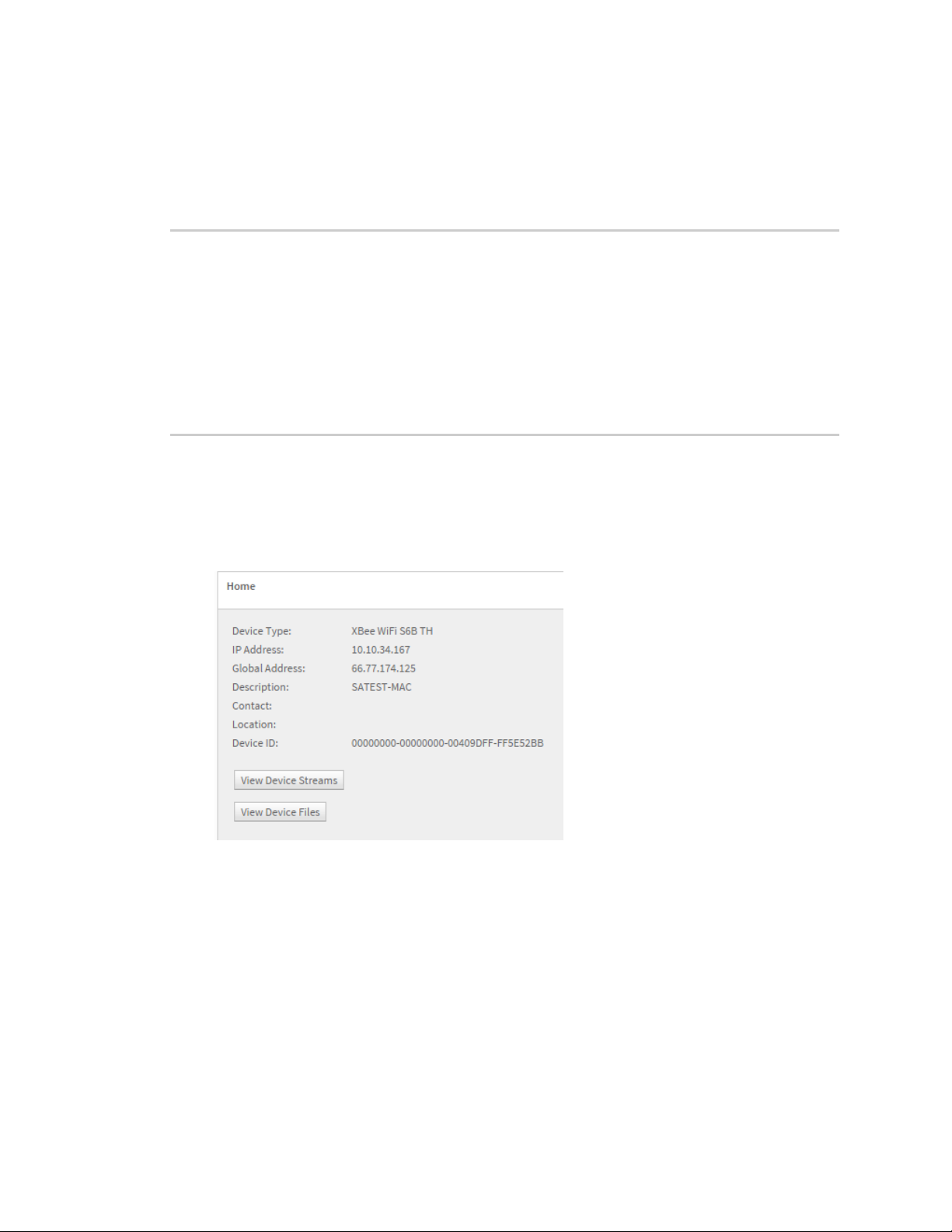
Configure the XBee Wi-Fi RF Module in Digi Remote Manager Populate and send a Device Request frame (0xB9)
Populate and send a Device Request frame (0xB9)
1. In Remote Manager, click Documentation > API Explorer.
2. Click Examples > SCI > Data Service > Send request. A sample XML file that you can modify
appears as seen in the following code sample:
<sci_request version="1.0">
<data_service>
<targets>
<device id="00000000-00000000-00000000-00000000"/>
</targets>
<requests>
<device_request target_name="myTarget">
my payload string
</device_request>
</requests>
</data_service>
</sci_request>
3. Under <targets> type the MAC address of the XBee Wi-Fi RF Module in this format:
00000000-00000000-010203FF-FF040506
where 01 to 06 are the first through sixth bytes of the MAC address, respectively, and 00 and
FF are literally 00 and FF. In Remote Manager, you can find the device MAC address in this
format in the device’s Home field.
4. Under <requests>, you can type a target name as desired, but any target name beginning with
XBee (case insensitive) is reserved for use on the XBee device itself and will not be sent out the
serial port.
5. Type the string that will be output in the device request. Both the target name and the device
request string depend on your application and the XBee device passes these strings on,
unmodified.
6. In the HTTP Method field, select the POST option button.
7. Click Send. The device response appears in the Web Services Responses pane.
XBee Wi-Fi RF Module User Guide
96
Page 97

Configure the XBee Wi-Fi RF Module in Digi Remote Manager Transparent mode data
Transparent mode data
The XBee Wi-Fi RF Module also supports Remote Manager transmissions and receptions in
Transparent mode. Transparent data is sent to Remote Manager using the Send Data interface and
Transparent data is received from Remote Manager using the Device Request interface. Some parts
of those interfaces are lost due to not using the API interface.
Send data to Remote Manager
The device can send serial data to Remote Manager as files or as binary data points. To make this
selection, use bit 4 of DO (Device Options). If you set DO bit 4, then the serially-connected host sends
Transparent data to Remote Manager as binary data points. Otherwise, it sends the data as a file.
Files are static and permanent. Data streams are dynamic and you can graph them to understand
changes.
AT command settings to put serial data in Remote Manager
AP (API Enable) command:
0: Transparent Mode
1: API Mode without escapes
2: API Mode with escapes
EQ (Remote Manager FQDN) command:
The URL for Remote Manager should be remotemanager.digi.com
DO (Device Options) command:
Bits 0-7: Encoded in Hex.
0: Enable Remote Manager (1), Disable (0).
1: Soft AP when ID = None. This has nothing to do with Remote Manager.
2: Send Transparent Data to Remote Manager (1), send to DL (0).
3: Send IO both to Remote Manager and DL (1), Remote Manager only (0).
4: Send Transparent data as a data stream (1), file data (0) – must have bit 2.
5: If bit 4 is 0, replace file (1), append to file (0).
Hence, the following values:
00: Do not use Remote Manager at all.
05: Send Transparent data to Remote Manager as a file which is appended (00000101).
/ws/FileData/~/00000000-00000000-00409DFF-FFxxxxxx/serial/0
25: Send transparent data to Remote Manager as a file which is overwritten (00100101)
/ws/FileData/~/00000000-00000000-00409DFF-FFxxxxxx/serial/0
15: Send transparent data to Remote Manager as a data point – encoded in BINARY
/ws/v1/streams/inventory/00000000-00000000-00409DFF-FF5DB54F/serial/0
/ws/DataPoint/00000000-00000000-00409DFF-FF5DB54F/serial/0
/ws/DataStream/00000000-00000000-00409DFF-FF5DB54F/serial/0
01: Connect to Remote Manager, but send Transparent data to the address and port of DL/DE using
the protocol in IP.
This is convenient if you want to use the TCP or UDP method for posting at datapoint.
XBee Wi-Fi RF Module User Guide
97
Page 98

Configure the XBee Wi-Fi RF Module in Digi Remote Manager Transparent mode data
Send files
The file name that is written on Remote Manager is named serial/0. The file type is text/plain. DO
(Device Options) bit 5 selects whether to append to an existing file or to replace it. If replacing an
existing file and the size of the data being sent exceeds the maximum frame size allowed (1400
bytes), then that frame isbroken up and only the last part shows up in the file because the last part
will replace rather than append to the first part.
Send binary data points
To send binary data points to Remote Manager in Transparent mode: set DO (Device Options) to 0x15
or 0x17, which means:
n Set DO to bit 4.
n Set DO bit 0 to enable Remote Manager.
n Set DO bit 2 so Transparent data goes to Remote Manager.
To view the files:
1. Double click the device.
2. Click Home.
3. Click the View Device Streams button.
or
1. Click Data Services > Data Streams.
2. In the Stream column, click the MAC address of the module/serial/0.
Receive data from Remote Manager
Transparent data is received from Remote Manager using the Device Request interface if the device is
operating in Transparent mode (AP = 0) and Remote Manager is enabled with DO bit 0. Only the raw
data is seen on the serial interface and the target string to which Remote Manager sent the data is
not available.
You must use API mode to see the target string. In Transparent mode, Remote Manager should not
request a response because none is given.
XBee Wi-Fi RF Module User Guide
98
Page 99

Operate in API mode
API mode overview 100
Use the AP command to set the operation mode 100
API frame format 100
API serial exchanges 104
XBee Wi-Fi RF Module User Guide
99
Page 100

Operate in API mode API mode overview
API mode overview
As an alternative to Transparent operating mode, you can use API operating mode. API mode provides
a structured interface where data is communicated through the serial interface in organized packets
and in a determined order. This enables you to establish complex communication between devices
without having to define your own protocol. The API specifies how commands, command responses
and device status messages are sent and received from the device using the serial interface or the
SPIinterface.
We may add new frame types to future versions of firmware, so build the ability to filter out additional
API frames with unknown frame types into your software interface.
Use the AP command to set the operation mode
Use AP (API Enable) to specify the operation mode:
AP command
setting Description
AP = 0
AP = 1
AP = 2
The API data frame structure differs depending on what mode you choose.
API frame format
An API frame consists of the following:
n Start delimeter
n Length
n Frame data
n Checksum
API operation (AP parameter = 1)
This is the recommended API mode for most applications. The following table shows the data frame
structure when you enable this mode:
Transparent operating mode, UARTserial line replacement with API modes
disabled. This is the default option.
API operation.
API operation with escaped characters (only possible on UART).
Frame fields Byte Description
Start delimiter 1 0x7E
Length 2 - 3 Most Significant Byte, Least Significant Byte
Frame data 4 - number (n) API-specific structure
Checksum n + 1 1 byte
XBee Wi-Fi RF Module User Guide
100
 Loading...