

Page 1

Digi International Inc.
11001 Bren Road East
Minnetonka, MN 55343
877 912-3444 or 952 912-3444
http://www.digi.com
XBee®/XBee-PRO® ZB RF Modules
ZigBee RF Modules by Digi International
Models: XBEE2, XBEEPRO2, PRO S2B
Hardware: S2 and S2B
Firmware Versions:
- 20xx - Coordinator - AT/Transparent Operation
- 21xx - Coordinator - API Operation
- 22xx - Router - AT/Transparent Operation
- 23xx - Router - API Operation
- 28xx - End Device - AT/Transparent Operation
- 29xx - End Device - API Operation
90000976_D
11/5/2009
Page 2

XBee®/XBee‐PRO®ZBRFModules
© 2009 Digi International, Inc. All rights reserved
Nopartofthecontentsofthismanualmaybetransmittedorreproducedinany
formorbyanymeanswithoutthewrittenpermissionofDigiInternational,Inc.
®isaregisteredtrademarkoftheZigBeeAlliance.
ZigBee
XBee®andXBee‐PRO®areregisteredtrademarksofDigiInternational,Inc.
Technical Support: Phone: (866) 765-9885 toll-free U.S.A. & Canada
(801) 765-9885 Worldwide
8:00 am - 5:00 pm [U.S. Mountain Time]
Live Chat: www.digi.com
Online Support: http://www.digi.com/support/eservice/login.jsp
Email: rf-experts@digi.com
©2009DigiInternational,Inc. 2
Page 3

XBee®/XBee‐PRO®ZBRFModules
Contents
Overview 6
What's New in 2x7x 6
Firmware 6
Manual 7
Key Features 8
Worldwide Acceptance 8
Specifications 9
Mechanical Drawings 10
SIF Header Interface 11
Mounting Considerations 11
Pin Signals 12
EM250 Pin Mappings 13
Design Notes 13
Power Supply Design 13
Recommended Pin Connections 13
Board Layout 14
Electrical Characteristics 16
RF Module Operation 17
Serial Communications 17
UART Data Flow 17
Serial Buffers 17
Serial Flow Control 18
Serial Interface Protocols 19
Modes of Operation 21
Idle Mode 21
Transmit Mode 21
Receive Mode 22
Command Mode 22
Sleep Mode 23
XBee ZigBee Networks 24
Introduction to ZigBee 24
ZigBee Stack Layers 24
Networking Concepts 24
Device Types 24
PAN ID 25
Operating Channel 26
ZigBee Application Layers: In Depth 26
Application Support Sublayer (APS) 26
Application Profiles 26
Coordinator Operation 27
Forming a Network 27
Channel Selection 28
PAN ID Selection 28
Security Policy 28
Persistent Data 28
XBee ZB Coordinator Startup 28
Permit Joining 29
Resetting the Coordinator 29
Leaving a Network 30
Replacing a Coordinator (Security Disabled Only)
30
Example: Starting a Coordinator 31
Example: Replacing a Coordinator (security dis-
abled) 31
Router Operation 31
Discovering ZigBee Networks 31
Joining a Network 32
Authentication 32
Persistent Data 32
XBee ZB Router Joining 32
Permit Joining 34
Joining Always Enabled 34
Joining Temporarily Enabled 34
Router Network Connectivity 34
Leaving a Network 36
Resetting the Router 37
Example: Joining a Network 37
End Device Operation 37
Discovering ZigBee Networks 37
Joining a Network 38
Parent Child Relationship 38
End Device Capacity 38
Authentication 38
Persistent Data 38
Orphan Scans 39
XBee: ZB End Device Joining 39
Parent Connectivity 40
Resetting the End Device 40
Leaving a Network 40
Example: Joining a Network 41
Channel Scanning 41
Managing Multiple ZigBee Networks 41
PAN ID Filtering 42
Preconfigured Security Keys 42
Permit Joining 42
Application Messaging 42
Data Transmission, Addressing, and Routing 43
©2009DigiInternaitonal,Inc. 3
Page 4

XBee®/XBee‐PRO®ZBRFModules
Contents
Addressing 43
64-bit Device Addresses 43
16-bit Device Addresses 43
Application Layer Addressing 43
Data Transmission 43
Broadcast Transmissions 44
Unicast Transmissions 44
Data Transmission Examples 46
RF Packet Routing 48
Link Status Transmission 48
AODV Mesh Routing 49
Many-to-One Routing 51
Source Routing 52
Encrypted Transmissions 55
Maximum RF Payload Size 56
Throughput 56
ZDO Transmissions 56
ZigBee Device Objects (ZDO) 57
Sending a ZDO Command 57
Receiving ZDO Commands and Responses 57
Transmission Timeouts 59
Unicast Timeout 59
Extended Timeout 59
Transmission Examples 60
Security 62
Security Modes 62
ZigBee Security Model 62
Network Layer Security 62
Frame Counter 63
Message Integrity Code 63
Network Layer Encryption and Decryption 63
Network Key Updates 64
APS Layer Security 64
Message integrity Code 64
APS Link Keys 64
APS Layer Encryption and Decryption 65
Network and APS Layer Encryption 65
Trust Center 65
Forming and Joining a Secure Network 65
Implementing Security on the XBee 66
Enabling Security 66
Setting the Network Security Key 66
Setting the APS Trust Center Link Key 66
Enabling APS Encryption 66
Using a Trust Center 67
XBee Security Examples 67
Example 1: Forming a network with security
(pre-configured link keys) 67
Example 2: Forming a network with security (obtaining keys during joining) 68
Network Commissioning and Diagnostics 69
Device Configuration 69
Device Placement 69
Link Testing 69
RSSI Indicators 70
Device Discovery 70
Network Discovery 70
ZDO Discovery 70
Joining Announce 70
Commissioning Pushbutton and Associate LED
71
Commissioning Pushbutton 71
Associate LED 72
Managing End Devices 74
End Device Operation 74
Parent Operation 74
End Device Poll Timeouts 75
Packet Buffer Usage 75
Non-Parent Device Operation 76
XBee End Device Configuration 76
Pin Sleep 76
Cyclic Sleep 78
Transmitting RF Data 81
Receiving RF Data 81
IO Sampling 82
Waking End Devices with the Commissioning
Pushbutton 82
Parent Verification 82
Rejoining 82
XBee Router/Coordinator Configuration 83
RF Packet Buffering Timeout 83
Child Poll Timeout 83
Transmission Timeout 83
Putting it all Together 84
Short Sleep Periods 84
Extended Sleep Periods 84
Sleep Examples 84
©2009DigiInternaitonal,Inc. 4
Page 5

XBee®/XBee‐PRO®ZBRFModules
Contents
XBee Analog and Digital IO Lines 86
IO Configuration 86
IO Sampling 86
Queried Sampling 88
Periodic IO Sampling 88
Change Detection Sampling 88
RSSI PWM 88
IO Examples 89
API Operation 90
API Frame Specifications 90
API Examples 92
API UART Exchanges 93
AT Commands 93
Transmitting and Receiving RF Data 93
Remote AT Commands 93
Source Routing 94
Supporting the API 94
API Frames 94
AT Command 94
AT Command - Queue Parameter Value 95
ZigBee Transmit Request 95
Explicit Addressing ZigBee Command Frame 97
Remote AT Command Request 99
Create Source Route 100
AT Command Response 101
Modem Status 101
ZigBee Transmit Status 102
ZigBee Receive Packet 103
ZigBee Explicit Rx Indicator 104
ZigBee IO Data Sample Rx Indicator 105
XBee Sensor Read Indicator 106
Node Identification Indicator 108
Remote Command Response 109
Over-the-Air Firmware Update Status 110
Route Record Indicator 111
Many-to-One Route Request Indicator 112
Sending ZigBee Device Objects (ZDO) Commands with the API 113
Sending ZigBee Cluster Library (ZCL) Commands with the API 115
Sending Public Profile Commands with the API
117
XBee Command Reference Tables 118
Module Support 128
X-CTU Configuration Tool 128
Customizing XBee ZB Firmware 128
Design Considerations for Digi Drop-In Net-
working 128
XBee Bootloader 128
Programming XBee Modules 129
Serial Firmware Updates 129
Invoke XBee Bootloader 129
Send Firmware Image 129
SIF Firmware Updates 130
Writing Custom Firmware 130
Regulatory Compliance 130
Enabling GPIO 1 and 2 130
Detecting XBee vs. XBee-PRO 131
Ensuring Optimal Output Power 131
Improving Low Power Current Consumption
132
XBee (non-PRO) Initialization: 13 2
When sleeping (end devices): 132
When waking from sleep (end devices): 132
Appendix A:Definitions 133
Appendix B: Agency Certifications 135
Appendix C:Migrating from ZNet 2.5 to XBee ZB
143
Appendix D:Additional Information 144
©2009DigiInternaitonal,Inc. 5
Page 6

1.Overview
This manual describes the operation of the XBee/XBeePRO ZB RF module, which consists of ZigBee firmware
loaded onto XBee S2 and S2B hardware, models: XBEE2,
XBEEPRO2 and PRO S2B. The XBee/XBee-PRO ZB RF
Modules are designed to operate within the ZigBee
protocol and support the unique needs of low-cost, lowpower wireless sensor networks. The modules require
minimal power and provide reliable delivery of data
between remote devices.
The modules operate within the ISM 2.4 GHz frequency band and are compatible with the
following:
• XBee RS-232 Adapter
• XBee RS-485 Adapter
• XBee Analog I/O Adapter
• XBee Digital I/O Adapter
• XBee Sensor
• XBee USB Adapter
•XStick
• ConnectPort X Gateways
• XBee Wall Router.
The XBee/XBee-PRO ZB firmware release can be installed on XBee ZNet or ZB modules. The XBee
ZB firmware is based on the EmberZNet 3.x ZigBee PRO Feature Set mesh networking stack, while
the XBee ZNet 2.5 firmware is based on Ember's proprietary "designed for ZigBee" mesh stack
(EmberZNet 2.5.x). ZB and ZNet 2.5 firmware are similar in nature, but not over-the-air
compatible. Devices running ZNet 2.5 firmware cannot talk to devices running the ZB firmware.
What's New in 2x7x
Firmware
XBee/XBee-PRO ZB firmware includes the following new features (compared with 2x6x):
• Using Ember stack version 3.4.1.
• Support for the PRO S2B with temperature compensati on and an overvoltage chec k. Within 15
seconds of the supply voltage exceeding 3.9V, the API will emit a 0x08 modem status (Overvoltage) message, and then the AT/API versions will do a watchdog reset.
• ZDO passthru added. If AO=3, then ZDO requests which are not supported by the stack will
be passed out the UART.
• An attempt to send an oversized packet (256+ bytes) will result in a Tx Status message with
a status code of 0x74.
• End devices have two speed polling. 7.5 seconds is the slow rate, which switches to the fast
rate to trasact with its parent. When transactions are done, it switches back to the slow rate.
• A new receive option bit (0x40) indicates if the packet came from an end device.
• If the extended timeout option is enabled, then use it because end devices need more time
than routers to ack their packets.
• An option bit (0x01) was added to disable APS retries.
• If an end device has not had its polls answered for 5 secs, it will leave and attempt to rejoin
the network.
• XBee S2B has a new TP command which returns the temperature compensation sensor reading in units if Celsius degrees.
• The PP command returns the power dBm setting when PL4 is selected.
• The PO command sets the slow polling rate on end devices. Range is 1-0x1770 in units of 10
msec (10 msec to 60 sec). Default is 0 which invokes a 100 msec delay.
©2009DigiInternational,Inc. 6
Page 7

XBee®/XBee‐PRO®ZBRFModules
• Rejoining now can proceed without a NR or NRO command after a Mgmt_Leave_req is processed.
• Command ranges were changed for the SC, IR, and LT commands.
• A PAN Id corruption problem was fixed.
See the 2x7x release notes for a complete list of new features and bug fixes at www.digi.com/
support.
Manual
The XBee/XBee-PRO/S2B ZB 2x7x manual includes the following corrections over the 2x6x
manual:
• Descriptions and specification for th e PRO S2B.
• SIF Header Interface, pin 8 relabeled as pin 10.
• Pin mappings for pins 22 and 24 updated.
• New modem status codes were added.
• Corrections to the ZigBee Receive Packet description.
• Description changes for the SC, PL, PP, AO, IR, %V, and PO commands.
• Updates to Appendix B.
©2009DigiInternational,Inc. 7
Page 8

XBee®/XBee‐PRO®ZBRFModules
High Performance, Low Cost
XBee
• Indoor/Urban: up to 133’ (40 m)
• Outdoor line-of-sight: up to 400’ (120 m)
• Transmit Power: 2 mW (3 dBm)
• Receiver Sensitivity: -96 dBm
XBee-PRO (S2)
• Indoor/Urban: up to 300’ (90 m), 200' (60
m) for International variant
• Outdoor line-of-sight: up to 1 mile (1600
m), 2500' (750 m) for International variant
• Transmit Power: 50mW (17dBm), 10mW
(10dBm) for International variant
• Receiver Sensitivity: -102 dBm
XBee-PRO (S2B)
• Indoor/Urban: up to 300’ (90 m), 200' (60
m) for International variant
• Outdoor line-of-sight: up to 1 mile (1600
m), 2500' (750 m) for International variant
• Transmit Power: 68mW (18dBm), 10mW
(10dBm) for International variant
• Receiver Sensitivity: -102 dBm
Advanced Networking & Security
Retries and Acknowledgements
DSSS (Direct Sequence Spread Spectrum)
Each direct sequence channel has over
65,000 unique network addresses available
Point-to-point, point-to-multipoint
and peer-to-peer topologies supported
Self-routing, self-healing and fault-tolerant
mesh networking
Low Power
XBee
• TX Peak Current: 40 mA (@3.3 V)
• RX Current: 40 mA (@3.3 V)
• Power-down Current: < 1 uA
XBee-PRO (S2)
• TX Peak Current: 295mA (170mA for
international variant)
• RX Current: 45 mA (@3.3 V)
• Power-down Current: < 10 uA
XBee-PRO (S2B)
• TX Peak Current: 205mA (117mA for
international variant)
• RX Current: 47 mA (@3.3 V)
• Power-down Current: < 10 uA
Easy-to-Use
No configuration necessary for out-of box
RF communications
AT and API Command Modes for
configuring module parameters
Small form factor
Extensive command set
Free X-CTU Software
(Testing and configuration software)
Free & Unlimited Technical Support
Key Features
Worldwide Acceptance
FCC Approval (USA) Refer to Appendix A for FCC Requirements.
Systems that contain XBee®/XBee-PRO® ZB RF Modules inherit Digi Certifications.
ISM (Industrial, Scientific & Medical) 2.4 GHz frequency band
Manufactured under ISO 9001:2000 registered standards
XBee®/XBee-PRO® ZB RF Modules are optimized for use in US, Canada, Europe,
Australia, and Japan (contact Digi for complete list of agency approvals).
©2009DigiInternational,Inc. 8
Page 9

XBee®/XBee‐PRO®ZBRFModules
Specifications
SpecificationsoftheXBee®/XBee‐PRO®ZBRFModule
Specification XBee XBee-PRO (S2) XBee-PRO (S2B)
Performance
Indoor/Urban Range up to 133 ft. (40 m)
Outdoor RF line-of-sight
Range
Transmit Power Output
RF Data Rate 250,000 bps 250,000 bps 250,000 bps
Data Throughput up to 35000 bps (see chapter 4) up to 35000 bps (see chapter 4) up to 35000 bps (see chapter 4)
Serial Interface Data Rate
(software selectable)
Receiver Sensitivity
Power Requirements
Supply Voltage 2.1 - 3.6 V 3.0 - 3.4 V 2.7 - 3.6 V
Operating Current
(Transmit, max output
power)
Operating Current
(Receive))
Idle Current (Receiver off) 15mA 15mA 15mA
Power-down Current
General
Operating Frequency
Band
Dimensions 0.960” x 1.087” (2.438cm x 2.761cm) 0.960 x 1.297 (2.438cm x 3.294cm) 0.960 x 1.297 (2.438cm x 3.294cm)
Operating Temperature -40 to 85º C (industrial) -40 to 85º C (industrial) -40 to 85º C (industrial)
Antenna Options
Networking & Security
Supported Network
Topologies
Number of Channels 16 Direct Sequence Channels 14 Direct Sequence Channels 15 Direct Sequence Channels
Addressing Options
Agency Approvals
United States (FCC Part
15.247)
Industry Canada (IC) IC: 4214A-XBEE2 IC: 1846A-XBEEPRO2 IC: 1846A-PROS2B
Europe (CE) ETSI ETSI ETSI
Australia C-Tick C-Tick C-Tick
Up to 300 ft. (90 m), up to 200 ft (60 m)
international variant
up to 400 ft. (120 m)
2mW (+3dBm), boost mode enabled
1.25mW (+1dBm), boost mode
disabled
1200 bps - 1 Mbps
(non-standard baud rates also
supported)
-96 dBm, boost mode enabled
-95 dBm, boost mode disabled
40mA (@ 3.3 V, boost mode
enabled)
35mA (@ 3.3 V, boost mode
disabled)
40mA (@ 3.3 V, boost mode
enabled)
38mA (@ 3.3 V, boost mode
disabled)
o
< 1 uA @ 25
ISM 2.4 GHz ISM 2.4 GHz ISM 2.4 GHz
Integrated Whip, Chip, RPSMA, or
U.FL Connector
Point-to-point, Point-to-multipoint,
Peer-to-peer, and Mesh
PAN ID and Addresses, Cluster IDs
and Endpoints (optional)
FCC ID: OUR-XBEE2 FCC ID: MCQ-XBEEPRO2 FCC ID: MCQ-PROS2B
C < 10 uA @ 25oC < 10 uA @ 25oC
Up to 1 mile (1600 m), up to 2500 ft
(750 m) international variant
50mW (+17 dBm)
10mW (+10 dBm) for International
variant
1200 bps - 1 Mbps
(non-standard baud rates also
supported)
-102 dBm -102 dBm
295mA (@3.3 V)
170mA (@3.3 V) international variant
45 mA (@3.3 V) 47 mA (@3.3 V)
Integrated Whip, Chip, RPSMA, or U.FL
Connector
Point-to-point, Point-to-multipoint, Peerto-peer, and Mesh
PAN ID and Add resses, Cluster IDs a nd
Endpoints (optional)
Up to 300 ft. (90 m), up to 200 ft (60 m)
international variant
Up to 1 mile (1600 m), up to 2500 ft (750 m)
international variant
63mW (+18 dBm)
10mW (+10 dBm) for International variant
1200 bps - 1 Mbps
(non-standard baud rates also supported)
205mA (@3.3 V)
117mA (@3.3 V) internation al variant
Integrated Whip, Integrated PCB, RPSMA,
or U.FL Connector
Point-to-point, Point-to-multipoint, Peer-topeer, and Mesh
PAN ID and Addresses, Cluster IDs and
Endpoints (optional)
©2009DigiInternational,Inc. 9
Page 10

XBee®/XBee‐PRO®ZBRFModules
SpecificationsoftheXBee®/XBee‐PRO®ZBRFModule
Specification XBee XBee-PRO (S2) XBee-PRO (S2B)
Japan R201WW07215215 R201WW08215142
RoHS Compliant Compliant Compliant
Mechanical Drawings
MechanicaldrawingsoftheXBee®/XBee‐PRO®ZBRFModules(antennaoptionsnotshown)
MechanicalDrawingsfortheRPSMAVari a n t
.
©2009DigiInternational,Inc. 10
Page 11

XBee®/XBee‐PRO®ZBRFModules
SIF Header Interface
The XBee/XBee-PRO ZB modules include a SIF programming header that can be used with
Ember's programming tools to upload custom firmware images onto the XBee module. The SIF
header orientation and pinout are shown below.
A male header can be populated on the XBee that mates with Ember's 2x5 ribbon cable. The male
header and ribbon cables are available from Samtec:
2x5 Male Header - FTSH-105-01-F-DV-K
2x5 Ribbon Cable - FFSD-05-D-12.00-01-N
Mounting Considerations
The XBee modules were designed to mount into a receptacle (socket) and therefore does not
require any soldering when mounting it to a board. The XBee-PRO Development Kits contain RS232 and USB interface boards which use two 20-pin receptacles to receive modules.
XBee‐PROModuleMountingtoanRS‐232InterfaceBoard.
The receptacles used on Digi development boards are manufactured by Century Interconnect.
Several other manufacturers pro vide compar able mounting sol utions; however, Digi currently uses
the following receptacles:
• Through-hole single-row receptacles -
Samtec P/N: MMS-110-01-L-SV (or equivalent)
• Through-hole single-row receptacles -
Mill-Max P/N: 831-43-0101-10-001000
• Surface-mount double-row receptacles -
Century Interconnect P/N: CPRMSL20-D-0-1 (or equivalent)
©2009DigiInternational,Inc. 11
Page 12

XBee®/XBee‐PRO®ZBRFModules
• Surface-mount single-row receptacles -
Samtec P/N: SMM-110-02-SM-S
Digi also recommends printing an outline of the module on the board to indicate the orientation the
module should be mounted.
Pin Signals
XBee®/XBee‐PRO®ZBRFModulePinNumber
(topsidesshown‐shieldsonbottom)
PinAssignmentsfortheXBee‐PROModules
Pin # Name Direction Description
1 VCC - Power supply
2 DOUT Output UART Data Out
3 DIN / CONFIG
4 DIO12 Either Digital I/O 12
5 RESET
6 RSSI PWM / DIO10 Either RX Signal Strength Indicator / Digital IO
7 DIO11 Either Digital I/O 11
8 [reserved] - Do not connect
9DTR
10 GND - Ground
11 DIO4 Either Digital I/O 4
12 CTS
13 ON / SLEEP
14 VREF Input
15 Associate / DIO5 Ei ther Associated Indicator, Digital I/O 5
16 RTS
17 AD3 / DIO3 Either Analog Input 3 or Digital I/O 3
18 AD2 / DIO2 Either Analog Input 2 or Digital I/O 2
19 AD1 / DIO1 Either Analog Input 1 or Digital I/O 1
20
(Low‐assertedsignalsaredistinguishedwithahorizontallineabovesignalname.)
Input UART Data In
Input Module Reset (reset pulse must be at least 200 ns)
/ SLEEP_RQ/ DIO8 Either Pin Sleep Control Line or Digital IO 8
/ DIO7 Ei ther
/ DIO6 Either
AD0 / DIO0 / Commissioning
Button
Output Module Status Indicator or Digital I/O 9
Either Analog Input 0, Digital IO 0, or Commissioning Button
Clear-to-Send Flow Control or Digital I/O 7. CTS, if enabled, is
an output.
Not used on this module. For compatibility with other XBee
modules, we recommend connecting this pin to a voltage
reference if Analog sampling is desired. Otherwise, connect to
GND.
Request-to-Send Flow Control, Digital I/O 6. RTS, if e nabled, is
an input.
• Signal Direction is specified with respect to the module
• See Design Notes section below for details on pin co nnections.
©2009DigiInternational,Inc. 12
Page 13

XBee®/XBee‐PRO®ZBRFModules
EM250 Pin Mappings
The following table shows how the EM250 pins are used on the XBee.
EM250 Pin Number XBee Pin Number Other Usage
13 (Reset) 5 Connected to pin 8 on 2x5 SIF header.
19 (GPIO 11) 16
20 (GPIO 12) 12
21 (GPIO 0)
22 (GPIO 1)
24 (GPIO 2)
25 (GPIO 3) 13
26 (GPIO 4 / ADC 0) 20 Connected to pin 9 on 2x5 SIF header.
27 (GPIO 5 / ADC 1) 19 Connected to pin 10 on 2x5 SIF header.
29 (GPIO 6 /ADC 2) 18
30 (GPIO 7 / ADC 3 17
31 (GPIO 8) 4
32 (GPIO 9) 2
33 (GPIO 10) 3
34 (SIF_CLK) Connected to pin 6 on 2x5 SIF header.
35 (SIF_MISO) Connected to pin 2 on 2x5 SIF header.
36 (SIF_MOSI) Connected to pin 4 on 2x5 SIF header.
37 (SIF_LOAD) Connected to pin 7 on 2x5 SIF header.
40 (GPIO 16) 7
41 (GPIO 15) 6
42 (GPIO 14) 9
43 (GPIO 13) 11
15
XBee
Tied to ground (module identification)
XBee-PRO (S2)
Low-asserting shutdown line for output power compensation circuitry.
XBee-PRO (S2B)
Used to communicate with Temp Sensor and control Shutdown for low power mode.
XBee
Not connected. Configured as output low.
XBee-PRO (S2)
Powers the output power compensation circuitry.
XBee-PRO (S2B)
Used to communicate with Temp Sensor and control Shutdown for low power mode.
Design Notes
The XBee modules do not specifically require any external circuitry or specific connections for
proper operation. However, there are some general design guidelines that are recommended for
help in troubleshooting and building a robust design.
Power Supply Design
Poor power supply can lead to poor radio performance especially if the supply voltage is not kept
within tolerance or is excessively noisy. To help reduce noise a 1uF and 8.2pF capacitor are
recommended to be placed as near to pin1 on the PCB as possible. If using a switching regulator
for your power supply, switching frequencies above 500kHz are preferred. Power supply ripple
should be limited to a maximum 250mV peak to peak.
Recommended Pin Connections
The only required pin connections are VCC, GND, DOUT and DIN. To support serial firmware
updates, VCC, GND, DOUT, DIN, RTS, and DTR should be connected.
©2009DigiInternational,Inc. 13
Page 14

XBee®/XBee‐PRO®ZBRFModules
All unused pins should be left disconnected. All inputs on the radio can be pulled high with 30k
internal pull-up resistors using the PR software command. No specific treatment is needed for
unused outputs.
For applications that need to ensu re th e l owe st sleep current, inputs should never be left floating.
Use internal or external pull-up or pull-down resistors, or set the unused I/O lines to outputs.
Other pins may be connected to external circuitry for convenience of operation including the
Associate LED pin (pin 15) and the Commissioning pin (pin 20). The Associate LED pin will flash
differently depending on the state of the module to the network, and a pushbutton attached to pin
20 can enable various join functions without having to send UART commands. Please see the
commissioning pushbutton and associate LED section in chapter 7 for more details. The source
and sink capabilities are limited to 4mA for all pins on the modu le.
The VRef pin (pin 14) is not used on this module. For compatibility with other XBee modules, we
recommend connecting this pin to a voltage reference if analog sampling is desired. Otherwise,
connect to GND.
Board Layout
XBee modules do not have any specific sensitivity to nearby processors, crystals or other PCB
components. Other than mechanical considerations, no special PCB placement is required for
integrating XBee radios except for those with integral antennas. In general, Power and GND tr aces
should be thicker than signal traces and be able to comfortably support the maximum currents.
The radios are also designed to be self sufficient and work with the integrated and external
antennas without the need for additional ground planes on the host PCB. However, considerations
should be taken on the choice of antenna and antenna location. Metal objects that are near an
antenna cause reflections and may reduce the ability for an antenna to efficiently radiate. Using an
integral antenna (like a wire whip antenna) in an enclosed metal box will greatly reduce the range
of a radio. For this type of application an external antenna would be a better choice.
External antennas should be positioned away from metal objects as much as possible. Metal
objects next to the antenna or between transmitting and receiving antennas can often block or
reduce the transmission distance. Some objects that are often overlooked are metal poles, metal
studs or beams in structures, concrete (it is usua lly reinforced with metal rods), metal enclosures,
vehicles, elevators, ventilation ducts, refrigerators and microwave ovens.
Wire Whip Antennas should be straight and perpendicular to the ground plane and/or chassis. It
should reside above or away from any metal objects like batteries, tall electrolytic capacitors or
metal enclosures. If the antenna is bent to fit into a tight space, it should be bent so that as much
of the antenna as possible is away from metal. Caution should be used when bending the antenna,
since this will weaken the solder joint where the antenna connects to the module. Antenna
elements radiate perpendicular to the direction they point. Thus a vertical antenna emits across
the horizon.
Embedded or Chip Antennas should not have any ground planes or metal objects above or below
the module at the antenna location. For best results the module should be in a plastic enclosure,
instead of metal one. It should be placed at t he edge of the PCB to which it is mounted. The
ground, power and signal planes should be vacant immediately below the antenna section (See
drawing for recommended keepout area).
©2009DigiInternational,Inc. 14
Page 15

XBee®/XBee‐PRO®ZBRFModules
©2009DigiInternational,Inc. 15
Page 16

XBee®/XBee‐PRO®ZBRFModules
Electrical Characteristics
DCCharacteristicsoftheXBee/XBee‐PRO
Symbol Parameter Condition Min Typical Max Units
VIL Input Low Voltage All Digital I nputs - - 0.2 * VCC V
V
IH
V
OL
V
OH
II
IN
I
OHS
I
OHH
I
OLS
I
OLH
I
OH + IOL
Input High Voltage All Digital Inputs 0.8 * VCC - - V
Output Low Voltage VCC >= 2.7 V - - 0.18*VCC V
Output High Voltage VCC >= 2.7 V 0.82*VCC - - V
Input Leakage Current
Output source current (standard)
Output source current (high
current)
Output sink current (standard
Output sink current (high current) RSSI/PWM, DIO10, DIO4 digital outputs 8 mA
Total output current for all I/O pins All digital outputs 40 mA
= VCC or GND, all inputs, per pin
V
IN
All digital outputs except
RSSI/PWM, DIO10, DIO4
- - 0.5uA uA
4mA
RSSI/PWM, DIO10, DIO4 digital outputs 8 mA
All digital inputs except
RSSI/PWM, DIO10, DIO4
4mA
©2009DigiInternational,Inc. 16
Page 17

2.RFModuleOperation
DIN (data in)
DIN (data in)
DOUT (data out )
DOUT (data out)
Serial Communications
The XBee RF Modules interface to a host device through a logic-level asynchronous serial port.
Through its serial port, the module can communicate with any logic and voltage compatible UART ;
or through a level translator to an y se rial devic e (for e xample: through a RS-232 or USB int erface
board).
UART Data Flow
Devices that have a UART interface can connect directly to the pins of the RF module as shown in
the figure below.
SystemDataFlowDiagraminaUART‐interfacedenvironment
(Low‐assertedsignalsdistinguishedwithhorizontallineoversignalname.)
Serial Data
Data enters the module UART through the DIN (pin 3) as an asynchronous serial signal. The signal
should idle high when no data is being transmitted.
Each data byte consists of a start bit (low), 8 data bits (least significant bit first) and a stop bit
(high). The following figure illustrates the serial bit pattern of data passing through the module.
UARTdatapacket0x1F(decimalnumberʺ31ʺ)astransmittedthroughtheRFmodule
ExampleDataFormatis8‐N‐1(bits‐parity‐#ofstopbits)
Serial communications depend on the two UAR Ts (the microcontroller's and the RF module's) to be
configured with compatible settings (baud rate, parity, start bits, stop bits, data bits).
The UART baud rate, parity, and stop bits settings on the XBee module can be configured with the
BD, NB, and SB commands respectively. See the command table in chapter 10 for details.
Serial Buffers
The XBee modules maintain small buffers to collect received serial and RF data, which is illustrated
in the figure below. The serial receive buffer collects incoming serial characters and holds them
until they can be processed. The serial transmit buffer collects data that is received via the RF link
that will be transmitted out the UART.
©2009DigiInternational,Inc. 17
Page 18

XBee®/XBee‐PRO®ZBRFModules
Serial
Receiver
Buffer
RF TX
Buffer
Transmitter
RF Switch
Antenna
Port
Receiver
Serial Transmit
Buffer
RF RX
Buffer
Processor
DIN
DOUT
CTS
RTS
TInternalDataFlowDiagram
Serial Receive Buffer
When serial data enters the RF module through the DIN Pin (pin 3), the data is st ored in the serial
receive buffer until it can be processed. Under certain conditions, the module may not be able to
process data in the serial receive buffer immediately. If large amounts of serial data are sent to
the module, CTS
Cases in which the serial receive buffer may become full and possibly overflow:
1.If the module is receiving a continuous stream of RF data, the data in the serial receive buffer
will not be transmitted until the module is no longer receiving RF data.
2.If the module is transmitting an RF data packet, the module may need to discover the destination address or establish a route to the destination. After transmitting the data, the module
may need to retransmit the data if an acknowledgment is not received, or if the transmission is
a broadcast. These issues could delay the processing of data in the serial receive buffer.
flow control may be required to avoid overflowing the serial receive buffer.
Serial Transmit Buffer
When RF data is received, the data is moved into the serial tr ansmit buffer and se nt out the UAR T.
If the serial transmit buffer becomes full enough such that all data in a received RF packet won’t fit
in the serial transmit buffer, the entire RF data packet is dropped.
Cases in which the serial transmit buffer may become full resulting in dropped RF
packets
1. If the RF data rate is set higher than the interface data rate of the module, the module
could receive data faster than it can send the data to the host.
2. If the host does not allow the module to transmit data out from the serial transmit buffer
because of being held off by hardware flow control.
Serial Flow Control
The RTS and CTS module pins can be used to provide RTS and/or CTS flow control. CTS flow
control provides an indication to the host to stop sending serial data to the module. RTS flow
control allows the host to signal the module to not send data in the serial transmit buffer out the
uart. RTS
CTS Flow Control
If CTS flow control is enabled (D7 command), when the serial receive buffer is 17 bytes away from
being full, the module de-asserts CTS
serial data. CTS
and CTS flow control are enabled using the D6 and D7 commands.
(sets it high) to signal to the host device to stop sending
is re-asserted after the serial receive buffer has 34 bytes of space.
©2009DigiInternational,Inc. 18
Page 19

XBee®/XBee‐PRO®ZBRFModules
RTS Flow Control
If RTS flow control is enabled (D6 command), data in the serial transmit buffe r will not be sent out
the DOUT pin as long as RTS
for long periods of time to avoid filling the serial transmit buffer. If an RF data packet is received,
and the serial transmit buffer does not have enough space for all of the data bytes, the entire RF
data packet will be discarded.
Note: If the XBee is sending data out the UART when RTS
could send up to 5 characters out the UART after RTS
Serial Interface Protocols
The XBee modules support both transparent and API (Application Programming Interface) serial
interfaces.
Transparent Operation
When operating in transparent mode, the modules act as a serial line replacement. All UART data
received through the DIN pin is queued up for RF transmission. When RF data is received, the data
is sent out through the DOUT pin. The module configuration parameters are configured using the
AT command mode interface.
Data is buffered in the serial receive buffer until one of the following causes the data to be
packetized and transmitted:
• No serial characters are received for the amount of time determined by the RO (Packetization
Timeout) parameter. If RO = 0, packetization begins when a character is received.
• The Command Mode Sequence (GT + CC + GT) is received. Any character buffered in the
serial receive buffer before the sequence is transmitted.
• The maximum number of characters that will fit in an RF packet is received.
RF modules that contain the following firmware versions will support Transparent Mode:
20xx (AT coordinator), 22xx (AT router), and 28xx (AT end device).
is de-asserted (set high). The host device should not de-assert RTS
is de-asserted (set high), the XBee
is de-asserted.
API Operation
API operation is an alternative to transparent operati on. The fr ame-bas ed API ext ends th e lev el to
which a host application can interact with the networking capabilities of the module. When in API
mode, all data entering and leaving the module is contained in frames that define operations or
events within the module.
Transmit Data Frames (received through the DIN pin (pin 3)) include:
• RF Transmit Data Frame
• Command Frame (equivalent to AT commands)
Receive Data Frames (sent out the DOUT pin (pin 2)) include:
• RF-received data frame
• Command response
• Event notifications such as reset, associate, disassociate, etc.
The API provides alternative means of configuring modules and routing data at the host
application layer. A host application can send data frames to the module that contain address and
payload information instead of using command mode to modify addresses. The module will send
data frames to the application containing status packets; as well as source, and payload
information from received data packets.
The API operation option facilitates many operations such as the examples cited below:
-> Transmitting data to multiple destinations without entering Command Mode
->Receive success/failure status of each transmitted RF packet
-> Identify the source address of each received packet
RF modules that contain the following firmware versions will support API operation: 21xx (API
coordinator), 23xx (API router), and 29xx (API end device).
©2009DigiInternational,Inc. 19
Page 20

XBee®/XBee‐PRO®ZBRFModules
A Comparison of Transparent and API Operation
The following table compares the advantages of transparent and API modes of operation:
Simple Interface All received serial data is transmitted unless the module is in command mode.
Easy to support It is easier for an application to support transparent operation and command mode
Easy to manage data
transmissions to multiple
destinations
Received data frames
indicate the sender's
address
Advanced ZigBee
addressing support
Advanced networking
diagnostics
Remote Configuration
Transparent Operation Features
API Operation Features
Transmitting RF data to mu ltiple remotes only requires changing the address in the API frame. This
process is much faster than in transparent operation where the app lication must e nter AT command
mode, change the address, exit command mode, and then transmit data.
Each API transmission can return a transmit status frame indicating the success or reason for
failure.
All received RF data API frames indicate the source address.
API transmit and receive frames can expose ZigBee addressing fields including source and
destination endpoints, cluster ID and profile ID. This makes it easy to support ZDO commands and
public profile traffic.
API frames can provide indication of IO samples from remote devices, and node identifica tion
messages.
Set / read configuration commands can be sent to remote devices to configure them as needed
using the API.
As a general rule of thumb, API firmware is recommended when a device:
• sends RF data to multiple destinations
• sends remote configuration commands to manage devices in the network
• receives IO samples from remote devices
• receives RF data packets from multiple devices, and the application needs to know which
device sent which packet
• must support multiple ZigBee endpoints, cluster IDs, and/or profile IDs
• uses the ZigBee Device Profile services.
If the above conditions do not apply (e.g. a sensor node, router, or a simp le application), then AT
firmware might be suitable. It is acceptable to use a mixture of devices running API and AT
firmware in a network.
©2009DigiInternational,Inc. 20
Page 21

XBee®/XBee‐PRO®ZBRFModules
16-bit Network
Address Discovery
Data Discarded
Successful
Transmi ssion
Yes
No
New
Transmission
16-bit Network
Add ress D iscovered?
Route Known?
Rou te Dis covered ?
16-bit Network
Address Known?
Rou te Discovery
Transmit Data
Idle Mode
No
Yes
No No
Yes Yes
Modes of Operation
Idle Mode
When not receiving or transm itting data, the RF modu le is in Idle Mode. The module shifts into the
other modes of operation under the following conditions:
• Transmit Mode (Serial data in the serial receive buffer is ready to be packetized)
• Receive Mode (Valid RF data is received through the antenna)
• Sleep Mode (End Devices only)
• Command Mode (Command Mode Sequence is issued)
Transmit Mode
When serial data is received and is ready for packetization, the RF module will exit Idle Mode and
attempt to transmit the data. The destination address determines which node(s) will receive the
data.
Prior to transmitting the dat a, th e m o dul e en su re s th at a 1 6-bi t n e twork address and route to the
destination node have been established.
If the destination 16-bit network address is not known, network address discovery will take place.
If a route is not known, route discovery will take place for the purpose of establishing a route to
the destination node. If a module with a matching network address is not discovered, the packet is
discarded. The data will be transmitted once a route is established. If route discovery fails to
establish a route, the packet will be discarded.
Tra n smitModeSequence
©2009DigiInternational,Inc. 21
Page 22

XBee®/XBee‐PRO®ZBRFModules
When data is transmitted from one node to another, a network-level acknowledgement is
transmitted back across the established route to the source node. This acknowledgement packet
indicates to the source node that the data packet was received by the destination node. If a
network acknowledgement is not received, the source node will re-transmit the data.
It is possible in rare circumstances for the destination to receiv e a data packet, but for the source
to not receive the network acknowledgment. In this case, the source will retransmit the data,
which could cause the destination to receive the same data packet multiple times. The XBee
modules do not filter out duplicate packets. The application should include provisions to address
this potential issue
See Data Transmission and Routing in chapter 4 for more information.
Receive Mode
If a valid RF packet is received, the data is transferred to the serial transmit buffer.
Command Mode
To modify or read RF Module parameters, the module must first enter into Command Mode - a
state in which incoming serial characters are interpreted as commands. Refer to the API Mode
section in chapter 9 for an alternate means of configuring modules.
AT Command Mode
To Enter AT Command Mode:
Send the 3-character command sequence “+++” and observe guard times before and after the
command characters. [Refer to the “Default AT Command Mode Sequence” below.]
Default AT Command Mode Sequence (for transition to Command Mode):
• No characters sent for one second [GT (Guard Times) parameter = 0x3E8]
• Input three plus characters (“+++”) within one second [CC (Command Sequence Character)
parameter = 0x2B.]
• No characters sent for one second [GT (Guard Times) parameter = 0x3E8]
Once the AT command mode sequence has been issued, the module sends an "OK\r" out the
DOUT pin. The "OK\r" characters can be delayed if the module has not finished transmitting
received serial data.
When command mode has been entered, the command mode timer is started (CT command), and
the module is able to receive AT commands on the DIN pin.
All of the parameter values in the sequence can be modified to reflect user preferences.
NOTE: Failure to enter AT Command Mode is most commonly due to baud rate mismatch. By default,
the BD (Baud Rate) parameter = 3 (9600 bps).
To Send AT Commands:
Send AT commands and parameters using the syntax shown below.
Figure2‐01.SyntaxforsendingATCommands
To read a parameter value stored in the RF module’s register, omit the parameter field.
The preceding example would change the RF module Destination Address (Low) to “0x1F”. To store
the new value to non-volatile (long term) memory, subsequently send the WR (Write) command.
For modified parameter values to persist in the module’s registry after a reset, changes must be
saved to non-volatile memory using the WR (Write) Command. Otherwise, parameters are
restored to previously saved values after the module is reset.
©2009DigiInternational,Inc. 22
Page 23

XBee®/XBee‐PRO®ZBRFModules
Command Response
When a command is sent to the module, the module will parse and execute the command. Upon
successful execution of a command, the module returns an “OK” message. If execution of a
command results in an error, the module returns an “ERROR” message.
Applying Command Changes
Any changes made to the configuration command registers through AT commands will not take
effect until the changes are applied. For example, sending the BD command to change the baud
rate will not change the actual baud r ate until changes are applied. Changes can be applied in one
of the following ways:
• The AC (Apply Changes) command is issued.
• AT command mode is exited.
To Exit AT Command Mode:
1. Send the ATCN (Exit Command Mode) command (followed by a carriage return).
[OR]
2. If no valid AT Commands are received within the time specified by CT (Command Mode
Timeout) Command, the RF module automatically returns to Idle Mode.
For an example of programming the RF module using AT Commands and descriptions of each configurable parameter, please see the Command Reference Table chapter.
Sleep Mode
Sleep modes allow the RF module to enter states of low power consumption when not in use. The
XBee RF modules support both pin sleep (sleep mode entered on pin transition) and cyclic sleep
(module sleeps for a fixed time). XBee sleep modes are discussed in detail in chapter 6.
©2009DigiInternational,Inc. 23
Page 24

3.XBeeZigBeeNetworks
Introduction to ZigBee
ZigBee is an open global standard built on the IEEE 802.15.4 MAC/PHY. ZigBee defines a network
layer above the 802.15.4 layers to support advanced mesh routing capabilities. The ZigBee
specification is developed by a growing consortium of companies that make up the ZigBee
Alliance. The Alliance is made up of over 300 members, including semiconductor, module, stack,
and software developers.
ZigBee Stack Layers
The ZigBee stack consists of several layers including the PHY, MAC, Network, Application Support
Sublayer (APS), and ZigBee Device Objects (ZDO) layers. Technically, an Application Framework
(AF) layer also exists, but will be grouped with the APS layer in remaining discussions. The ZigBee
layers are shown in the figure below.
A description of each layer appears in the following table:
ZigBee Layer Description
PHY Defines the physical operation of the ZigBee device
MAC Manages RF data transactions between neighboring
Network Adds routing capabilities that allows RF data packets
APS (AF) Application layer that defines various addressing
ZDO Application layer that provides device and service
including receive sensitivity , channel reje ction, outpu t
power, number of channels, chip modulation, and
transmission rate specifications. Most ZigBee
applications operate on the 2.4 GHz ISM band at a
250kbps data rate. See the IEEE 802.15.4
specification for details.
devices (point to point). The MAC includes services
such as transmission retry and acknowledgment
management, and collision avoidance techniques
(CSMA-CA).
to traverse multiple devices (multiple "hops") to route
data from source to destination (peer to peer).
objects including profiles, clusters, and endpoints.
discovery features and advanced network
management capabilities.
Networking Concepts
Device Types
ZigBee defines three different device types: coordinator, router, and end device.
Node Types / Sample of a Basic ZigBee Network Topology
A coordinator has the following characteristics: it
• Selects a channel and PAN ID (both 64-bit and 16-bit) to start the network
• Can allow routers and end devices to join the network
• Can assist in routing data
• Cannot sleep--should be mains powered
• Can buffer RF data packets for sleeping end device children.
©2009DigiInternational,Inc. 24
Page 25

XBee®/XBee‐PRO®ZBRFModules
A router has the following characteristics: it
• Must join a ZigBee PAN before it can transmit, receive, or route data
• After joining, can allow routers and end devices to join the network
• After joining, can assist in routing data
• Cannot sleep--should be mains powered.
• Can buffer RF data packets for sleeping end device children.
An end device has the following characteristics: it
• Must join a ZigBee PAN before it can transmit or receive data
• Cannot allow devices to join the network
• Must always transmit and receive RF data through its parent. Cannot route data.
• Can enter low power modes to conserve power and can be battery-powered.
An example of such a network is shown below:
In ZigBee networks, the coordinator must select a P AN ID (64-bi t and 16-bit ) and channel to start
a network. After that, it behaves essentially like a router. The coordinator and routers can allow
other devices to join the network and can route data.
After an end device joins a router or coordinator, it must be able to transmit or receive RF data
through that router or coordinator. The router or coordinator that allowed an end device to join
becomes the "parent" of the end device. Since the end device can sleep, the parent must be able
to buffer or retain incoming data packets destined for the end device until the end device is able to
wake and receive the data.
PAN ID
ZigBee networks are called personal area networks or P ANs. Each network is defined with a unique
PAN identifier (P AN ID ). Thi s i den ti fie r is common among all devices of the same network. ZigBee
devices are either preconfigured with a PAN ID to join, or they can discovery nearby networks and
select a PAN ID to join.
ZigBee supports both a 64-bit and a 16-bit PAN ID. Both PAN IDs are used to uniquely identify a
network. Devices on the same ZigBee network must share the same 64-bit and 16-bit PAN IDs. If
multiple ZigBee networks are operating within range of each other, each should have unique PAN
IDs.
The 16-bit PAN ID is used as a MAC layer addressing field in all RF data transmissions between
devices in a network. However, due to the limited addressing space of the 16-bit PAN ID (65,535
possibilities), there is a possibility that multiple ZigBee networks (within range of each other)
could use the same 16-bit PAN ID . To resolve potential 16-bit PAN ID conflicts, the ZigBee Alliance
created a 64-bit PAN ID.
The 64-bit PAN ID (also called the extended PAN ID), is intended to be a unique, non-duplicated
value. When a coordinator starts a network, it can either start a network on a preconfigured 64-bit
PAN ID, or it can select a random 64-bit PAN ID. The 64-bit PAN ID is used during joining; if a
device has a preconfigured 64-bit PAN ID, it will only join a network with the same 64-bit PAN ID.
Otherwise, a device could join any detected PAN and inherit the PAN ID from the network when it
joins. The 64-bit PAN ID is included in all ZigBee beaco ns and is used in 16-bit PAN ID conflict
resolution.
©2009DigiInternational,Inc. 25
Page 26

XBee®/XBee‐PRO®ZBRFModules
Routers and end devices are typically configured to join a network with any 16-bit PAN ID as long
as the 64-bit PAN ID is valid. Coordinators typically select a random 16-bit PAN ID for their
network.
Since the 16-bit PAN ID only allows up to 65,535 unique values, and since the 16-bit PAN ID is
randomly selected, provisions exist in ZigBee to detect if two networks (with different 64-bit PAN
IDs) are operating on the same 16-bit PAN ID. If such a conflict is detected, the ZigBee stack can
perform PAN ID conflict resolution to change the 16-bit PAN ID of the network in order to resolve
the conflict. See the ZigBee specification for details.
To summarize, ZigBee routers and end devices should be configured with the 64-bit PAN ID of the
network they want to join. They typically acquire the 16-b it PAN ID when they join a network.
Operating Channel
ZigBee utilizes direct-sequ ence s pread spectru m modulation and oper ates on a fixe d channel. The
802.15.4 PHY defines 16 operating channels in the 2.4 GHz frequency band. XBee modules
support all 16 channels and XBee-PRO modules support 14 of the 16 channels.
ZigBee Application Layers: In Depth
This section provides a more in-depth look at the ZigBee application stack layers (APS, ZDO)
including a discussion on ZigBee endpoints, clusters, and profiles. Much of the material in this
section can introduce unnecessary details of the ZigBee stack that are not required in many cases.
Skip this section if
• The XBee does not need to interoperate or talk to non-Digi ZigBee devices
• The XBee simply needs to send data between devices.
Read this section if
• The XBee may talk to non-Digi ZigBee devices
• The XBee requires network management and discovery capabilities of the ZDO layer
• The XBee needs to operate in a public application profile (smart energy, home automation,
etc.)
Application Support Sublayer (APS)
The APS layer in ZigBee adds support for application profiles, cluster IDs, and endpoints.
Application Profiles
Application profiles specify various device descriptions including required functionality for various
devices. The collection of device descriptions forms an application profile. Application profiles can
be defined as "Public" or "Private" profiles. Private profiles are defined by a manufacturer whereas
public profiles are defined, developed, and maintained by the ZigBee Alliance. Each application
profile has a unique profile identifier assigned by the ZigBee Alliance.
Examples of public profiles include:
• Home Automation
• Smart Energy
• Commercial Building Automation
The Smart Energy profile, for example, defines various device types including an energy service
portal, load controller, thermostat, in-home display, etc. The Smart Energy profile defines required
functionality for each device type. For example, a load controller must respond to a defined
command to turn a load on or off. By defining standard communication protocols and device
functionality, public profiles allow interoperable ZigBee solutions to be developed by independent
manufacturers.
Digi XBee ZB firmware operates on a private profile called the Digi Drop-In Networking profile.
However, the API firmware in the module can be used in many cases to talk to devices in public
profiles or non-Digi private profiles. See the API Operations chapter for details.
©2009DigiInternational,Inc. 26
Page 27

XBee®/XBee‐PRO®ZBRFModules
Clusters
A cluster is an application message type defined within a profile. Clusters are used to specify a
unique function, service, or action. For example, the following are some clusters defined in the
home automation profile:
• On/Off - Used to switch devices on or off (lights, thermostats, etc.)
• Level Control - Used to control devices that can be set to a level between on and off
• Color Control - Controls the color of color capable devices.
Each cluster has an associated 2-byte cluster identifi er (cluster ID). The cluster ID is inc luded in all
application transmissions. Clusters often have associated request and response messages. For
example, a smart energy gateway (service portal) might send a load control event to a load
controller in order to schedule turning on or off an appliance. Upon executing the event, the load
controller would send a load control report message back to the gateway.
Devices that operate in an application profile (private or public) must respond correctly to all
required clusters. For example, a light switch that will operate in the home automation public
profile must correctly implement the On/Off and other required clusters in order to interoperate
with other home automation devices. The ZigBee Alliance has defined a ZigBee Cluster Library
(ZCL) that contains definitions or various general use clusters that could be implemented in any
profile.
XBee modules implement various clusters in the Digi private profile. In addition, the API can be
used to send or receive messages on any cluster ID (and profile ID or endpoint). See the Explicit
Addressing ZigBee Command API frame in chapter 3 for details.
Endpoints
The APS layer includes supports for endpoints. An endpoint can be thought of as a running
application, similar to a TCP/IP port. A single device can support one or more endpoints. Each
application endpoint is identified by a 1-byte value, ranging from 1 to 240. Each defined endpoint
on a device is tied to an application profile. A device could, for example, implement one endpoint
that supports a Smart Energy load controller, and another endpoint that supports other
functionality on a private profile.
ZigBee Device Profile
Profile ID 0x0000 is reserved for the ZigBee Device Profile. This profile is implemented on all
ZigBee devices. Device Profile defines many device and service discovery features and network
management capabilities. Endpoint 0 is a reserved endpoint that supports the ZigBee Device
Profile. This endpoint is called the ZigBee Device Objects (ZDO) endpoint.
ZigBee Device Objects (ZDO)
The ZDO (endpoint 0) supports the discovery and management capabilities of the ZigBee Device
Profile. A complete listing of all ZDP services is included in the ZigBee specification. Each service
has an associated cluster ID.
The XBee ZB firmware allows applications to e asily send ZDO messages to devices in the networ k
using the API. See the ZDO Transmissions section in chapter 4 for details.
Coordinator Operation
Forming a Network
The coordinator is responsible for selecting the channel, PAN ID (16-bit and 64-bit), security
policy, and stack profile for a network. Since a coordinator is the only device type that can start a
network, each ZigBee network must have one coordinator. After the coordinator has started a
network, it can allow new devices to join the network. It can also route data packets and
communicate with other devices on the network.
To ensure the coordinator starts on a good channel and unused PAN ID, the coordinator performs
a series of scans to discover any RF activity on different channels (energy scan) and to discover
©2009DigiInternational,Inc. 27
Page 28

XBee®/XBee‐PRO®ZBRFModules
any nearby operating PANs (PAN scan). The process for selecting the channel and PAN ID are
described in the following sections.
Channel Selection
When starting a network, the coordinator must select a "good" channel for the net work to oper ate
on. To do this, it performs an energy scan on multiple channels (frequencies) to detect energy
levels on each channel. Channels with excessive energy levels are removed from its list of
potential channels to start on.
PAN ID Selection
After completing the energy scan, the coordinator scans its list of potential channels (remaining
channels after the energy scan) to obtain a list of neighboring PANs. To do this, the coordinator
sends a beacon request (broadcast) transmission on each potential channel. All nearby
coordinators and routers (that have already joined a ZigBee network) will respond to the beacon
request by sending a beacon back to the coordinator. The beacon contains information about the
PAN the device is on, including the PAN identifiers (16-bit and 64-bit). This scan (collecting
beacons on the potential channels) is typically called an active scan or PAN scan.
After the coordinator completes the channel and PAN scan, it selects a random channe l and
unused 16-bit PAN ID to start on.
Security Policy
The security policy determines wh ich devices are allowed to join the network, and which device(s)
can authenticate joining devices. See chapter 5 for a detailed discussion of various security
policies.
Persistent Data
Once a coordinator has started a network, it retains the following information through power cycle
or reset events:
•PAN ID
•Operating channel
• Security policy and frame counter values
• Child table (end device children that are joined to the coordinator).
The coordinator will retain this information indefinitely until it leaves the network. Wh en the
coordinator leaves a network and starts a new network, the previous PAN ID, operating channel,
and child table data are lost.
XBee ZB Coordinator Startup
The following commands control the coordinator network formation process.
Networkformationcommandsusedbythecoordinatortoformanetwork.
Command Description
ID Used to determine the 64-bit PAN ID. If set to 0 (default), a random 64-bit PAN ID will be selected.
SC Determines the scan channels bitmask (up to 16 channels) used by the coordinator when forming a
SD Set the scan duration period. This value determines how long the coordinator performs an energy scan or
ZS Set the ZigBee stack profile for the netw ork.
EE Enable or disable security in the network.
network. The coordinator will perform an energy scan on all enabled SC channels. It will then perform a
PAN ID scan and th en form the network on one of the SC channels.
PAN ID scan on a given cha nnel.
©2009DigiInternational,Inc. 28
Page 29

XBee®/XBee‐PRO®ZBRFModules
NK Set the network security key for the network. If set to 0 (default), a random network security key will be
KY Set the trust center link key for the network. If set to 0 (default), a random link key will be used.
EO Set the security policy for the network.
Once the coordinator starts a network, the network configuration settings and child table data
persist through power cycles as mentioned in the "Persistent Data" section.
When the coordinator has successfully started a network, it
These behaviors are configurable using the following commands:
Command Description
NJ Sets the permit-join time on the coordinator,
D5 Enables the Associate LED functionality.
LT Sets the Associate LED blink time when
If any of the command values in the network formation commands table changes, the coordinator
will leave its current network and start a new network, possibly on a different channel. Note that
command changes must be applied (AC or CN command) before taking effect.
used.
• Allows other devices to join the network for a time (see NJ command)
•Sets AI=0
• Starts blinking the Associate LED
• Sends an API modem status frame ("coordinator started") out the UART (API firmware only).
measured in seconds.
joined. Default is 1 blink per second.
Permit Joining
The permit joining attribute on the coordinator is configurable with the NJ command. NJ can be
configured to always allow joining, or to allow joining for a short time.
Joining Always Enabled
If NJ=0xFF (default), joining is permanently enabled. This mode should be used carefully. Once a
network has been deployed, the application should strongly consider disabling joining to prevent
unwanted joins from occurring.
Joining Temporarily Enabled
If NJ < 0xFF, joining will be enabled only for a number of seconds, based on the NJ parameter. The
timer is started once the XBee joins a network. Joining will not be re-enabled if the module is
power cycled or reset. The following mechanisms can restart the permit-joining timer:
• Changing NJ to a different value (and applying changes with the AC or CN commands)
• Pressing the commissioning button twice (enables joining for 1 minute)
• Issuing the CB command with a parameter of 2 (software emulation of a 2 button press enables joining for 1 minute).
Resetting the Coordinator
When the coordinator is reset or power cycled, it checks its PAN ID, operating channel and stack
profile against the network configuration settings (ID, CH, ZS). It also verifies the saved security
policy against the security configuration settings (EE, NK, KY). If the coordinator's PAN ID,
operating channel, stack profile, or security policy is not valid based on its network and security
configuration settings, then the coordinator will leave the network and attempt to form a new
network based on its network formation command values.
To prevent the coordinator from leaving an existing network, the WR command should be issued
after all network formation commands have been configured in order to retain these settings
through power cycle or reset events.
©2009DigiInternational,Inc. 29
Page 30

XBee®/XBee‐PRO®ZBRFModules
Leaving a Network
There are a couple of mechanisms that will caus e the coordinator to leav e its current P AN and start
a new network based on its network formation parameter values. These include the following:
• Change the ID command such that the current 64-bit PAN ID is invalid.
• Change the SC command such that the current channel (CH) is not included in the channel
mask.
• Change the ZS or any of the security command values (excluding NK).
• Issue the NR0 command to cause the coordinator to leave.
• Issue the NR1 command to send a broadcast transmission, causing all devices in the network
to leave and migrate to a different channel.
• Press the commissioning button 4 times or issue the CB command with a parameter of 4.
Note that changes to ID, SC, ZS, and security command values only take effect when changes are
applied (AC or CN commands).
Replacing a Coordinator (Security Disabled Only)
In rare occasions, it may become necessary to replace an existing coordinator in a network with a
new physical device. If security is not enabled in the network, a replacement XBee coordinator can
be configured with the PAN ID (16-bit and 64-bit) , channel, and stack profil e settings of a running
network in order to replace an existing coordinator.
NOTE: Having two coordinators on the same channel, stack profil e, and P AN ID (16-bit and 64-bit)
can cause problems in the network and should be avoided. When replacing a coordinator, the old
coordinator should be turned off before starting the new coordinator.
To replace a coordinator, the following commands should be read from a device on the network:
AT C o m m and Description
OP Read the operating 64-bit PAN
OI Read the operating 16-bit PAN
CH Read the operating channel.
ZS Read the stack profile.
Each of the commands listed above can be read from any device on the network. (These
parameters will be the same on all devi ces in t he network. ) Af ter re ading the se comman ds from a
device on the network, these parameter values should be programmed into the new coordinator
using the following commands.
AT C o m m and Description
ID Set the 64-bit PAN ID to match
II Set the initial 16-bit PAN ID to
SC Set the scan channels bitmask
ID.
ID.
the read OP value.
match the read OI value.
to enable the read operating
channel (CH command). For
example, if the operating
channel is 0x0B, set SC to
0x0001. If the operating channel
is 0x17, set SC to 0x1000.
©2009DigiInternational,Inc. 30
Page 31

XBee®/XBee‐PRO®ZBRFModules
ZS Set the stack profile to match the
Note: II is the initial 16-bit PAN ID. Under certain conditions, the ZigBee stack can change the 16bit PAN ID of the network. For this reason, the II command cannot be saved using the WR
command. Once II is set, the coordinator leaves the network and starts on the 16-bit PAN ID
specified by II.
read ZS value.
Example: Starting a Coordinator
1. Set SC and ID to the desired scan channels and PAN ID values. (The defaults should suffice.)
2. If SC or ID is changed from the default, issue the WR command to save the changes.
3. If SC or ID is changed from the default, apply changes (make SC and ID changes take effect)
either by sending the AC command or by exiting AT command mode.
4. The Associate LED will start blinking once the coordinator has selected a channel and PAN ID.
5. The API Modem Status frame ("Coordinator Started") is sent out the UART (API firmware only).
6. Reading the AI command (association status) will return a value of 0, indicati ng a successful
startup.
7. Reading the MY command (16-bit address) will return a value of 0, the ZigBee-defined 16-bit
address of the coordinator.
After startup, the coordinator will allow joining based on its NJ value.
Example: Replacing a Coordinator (security disabled)
1. Read the OP, OI, CH, and ZS commands on the running coordinator.
2. Set the ID, SC, and ZS parameters on the new coordinator, followed by WR command to save
these parameter values.
3. Turn off the running coordinator.
4. Set the II parameter on the new coordinator to match the read OI value on the old coordinator.
5. Wait for the new coordinator to start (AI=0).
Router Operation
Routers must discover and join a valid ZigBee network before they can participate in a ZigBee
network. After a router has joined a network, it can allow new devices to join the network. It can
also route data packets and communicate with other devices on the network.
Discovering ZigBee Networks
To discover nearby ZigBee networks, the router performs a PAN (or active) scan, just like the
coordinator does when it starts a network. During the PAN scan, the router sends a beacon
request (broadcast) transmission on the first channel in its scan channels list. All nearby
coordinators and routers operating on that channel (that are already part of a ZigBee network)
respond to the beacon request by sending a beacon back to the router. The beacon contains
information about the PAN the nearby device is on, including the PAN identifier (PAN ID), and
whether or not joining is allowed. The router evaluates each beacon received on the channel to
determine if a valid PAN is found. A router considers a PAN to be valid if the PAN:
• Has a valid 64-bit PAN ID (PAN ID matches ID if ID > 0)
• Has the correct stack profile (ZS command)
• Is allowing joining.
If a valid PAN is not found, the router performs the PAN scan on the next channel in its scan
channels list and continues scanning until a valid network is found, or until all channels have been
©2009DigiInternational,Inc. 31
Page 32

XBee®/XBee‐PRO®ZBRFModules
scanned. If all channels have been scanned and a valid PAN was not discovered, all channels will
be scanned again.
The ZigBee Alliance requires that certified solutions not send beacon request messages too
frequently . To meet certification requirements, the XBee firmware attempts 9 scans per minute for
the first 5 minutes, and 3 scans per minute thereafter. If a valid PAN is within range of a joining
router, it should typically be discovered within a few seconds.
Joining a Network
Once the router discovers a v alid network, it sends an association request to the device that sent a
valid beacon requesting a join on the ZigBee network. The device allowing the join then sends an
association response frame that either allows or denies the join.
When a router joins a network, it receives a 16-bit address from the device that allowed the join.
The 16-bit address is randomly selected by the device that allowed the join.
Authentication
In a network where security is enabled, the router must then go through an authentication
process. See the Security chapter for a discussion on security and authentication.
After the router is joined (and authenticated, in a secure network), it can allow new devices to join
the network.
Persistent Data
Once a router has joined a network, it retains the following information through power cycle or
reset events:
•PAN ID
•Operating channel
• Security policy and frame counter values
• Child table (end device children that are joined to the coordinator).
The router will retain this information indefinitely until it leaves the network. When the router
leaves a network, the previous PAN ID, operating channel, and child table data are lost.
XBee ZB Router Joining
When the router is powered on, if it is not already joined to a valid ZigBee network, it immediately
attempts to find and join a valid ZigBee network.
Note: The DJ command can be set to 1 to disable joining. The DJ parameter cannot be written wit h
WR, so a power cycle always clears the DJ setting.
©2009DigiInternational,Inc. 32
Page 33

XBee®/XBee‐PRO®ZBRFModules
The following commands control the router joining process.
Command Description
ID Sets the 64-bit PAN ID to join. Setting ID=0 allows the router to join any
64-bit PAN ID.
SC Set the scan channels bitmask that determines which channels a router
SD Set the scan duration, or time that th e router will listen for beacons on
ZS Set the stack profile on the device.
EE Enable or disable security in the network. This must be set to match the
KY Set the trust center link key. If set to 0 (default), t he link key is expect ed to
will scan to find a valid network. SC on the router should be se t to match
SC on the coordinator. For example, setting SC to 0x281 enables
scanning on channels 0x0B, 0x12, and 0x14, in that order.
each channel.
EE value (security policy) of the coordinator.
be obtained (unencrypted) during joining.
Once the router joins a network, the network configuration settings and child table data persist
through power cycles as mentioned in the "Persistent Data" section previously. If joining fails, the
status of the last join attempt can be read in the AI command register.
If any of the above command values change, when command register changes are applied (AC or
CN commands), the router will leave its current network and attempt to discover and join a new
valid network.
When a ZB router has successfully joined a network, it:
• Allows other devices to join the network for a time
•Sets AI=0
• Starts blinking the Associate LED
• Sends an API modem status frame ("associated") out the UART (API firmware only).
©2009DigiInternational,Inc. 33
Page 34

XBee®/XBee‐PRO®ZBRFModules
These behaviors are configurable using the following commands:
Command Description
NJ Sets the permit-join time on
D5 Enables the Associate LED
LT Sets the Associate LED blink
Permit Joining
The permit joining attribute on the router is configurable with the NJ command. NJ can be
configured to always allow joining, or to allow joining for a short time.
Joining Always Enabled
the router, or the time that it
will allow new devices to join
the network, measured in
seconds. If NJ=0xFF, permit
joining will always be enabled.
functionality.
time when joined. Default is 2
blinks per second (router).
If NJ=0xFF (default), joining is permanently enabled. This mode should be used carefully. Once a
network has been deployed, the application should strongly consider disabling joining to prevent
unwanted joins from occurring.
Joining Temporarily Enabled
If NJ < 0xFF, joining will be enabled only for a number of seconds, based on the NJ parameter. The
timer is started once the XBee joins a network. Joining will not be re-enabled if the module is
power cycled or reset. The following mechanisms can restart the permit-joining timer:
• Changing NJ to a different value (and applying changes with the AC or CN commands)
• Pressing the commissioning button twice (enables joining for 1 minute)
• Issuing the CB command with a parameter of 2 (software emulation of a 2 button press enables joining for 1 minute)
• Causing the router to leave and rejoin the network.
Router Network Connectivity
Once a router joins a ZigBee network, it remains connected to the network on the same channel
and PAN ID as long as it is not forced to leave. (See Leaving a Network section for details.) If the
scan channels (SC), PAN ID (ID) and security settings (EE, KY) do not change after a power cycle,
the router will remain connected to the network after a power cycle.
If a router may physically move out of range of the network it initially joined, the application
should include provisions to detect if the router can still communicate with the original network. If
communication with the original network is lo st , the application may choose to force the router to
leave the network (see Leaving a Network section for details). The XBee firmware includes two
provisions to automatically detect the presence of a network, and leave if the check fails.
Power-On Join Verification
The JV command (join verification) enables the power-on join verification check. If enabled, the
XBee will attempt to discover the 64-bit address of the coordinator when it first joins a network.
Once it has joined, it will also attempt to discover the 64-bit address of the coordinator after a
power cycle event. If 3 discovery attempts fail, the router will leave the network and try to join a
new network. Power-on join verification is disabled by default (JV defaults to 0).
©2009DigiInternational,Inc. 34
Page 35

XBee®/XBee‐PRO®ZBRFModules
Network Watchdog
The NW command (network watchdog timeout) can be used for a powered router to periodically
check for the presence of a coordinator to verify network connectivity . The NW command specifies
a timeout in minutes where the router must receive communication from the coordinator or data
collector. The following events restart the network watchdog timer:
• RF data received from the coordinator
• RF data sent to the coordinator and an acknowledgment was received
• Many-to-one route request was received (from any device)
• Changing the value of NW.
If the watchdog timer expires (no valid data received for NW time), the router will attempt to
discover the 64-bit address of the coordinator. If the address cannot be discovered, the router
records one watchdog timeout. Once three consecutive network watchdog timeouts have expired
(3 * NW) and the coordinator has not responded to the address discovery attempts, the router will
leave the network and attempt to join a new network. Anytime a router receives valid data from
the coordinator or data collector, it will clear the watchdog timeouts counter and restart the
watchdog timer. The watchdog timer (NW command) is settable to several days. The network
watchdog feature is disabled by default (NW defaults to 0).
©2009DigiInternational,Inc. 35
Page 36

XBee®/XBee‐PRO®ZBRFModules
Clear Network Watchdog Failure Count
Restart Network Watchdog Timer
Received RF
Communi cation from
Coordinator or Data
Collector
Yes
Network Watchdog
Timer Expired?
No
No
Discover Coordinator
Yes
Coordinator
Found?
Yes
Network Watchdog Failure
Count +=1
No
Network
Watchdog
Failure Count
=3 ?
Leave
Yes
No
Network Watchdog Behavior
Leaving a Network
There are a couple of mechanisms that will cause the router to leave its current PAN and attempt
to discover and join a new network based on its network joining parameter values.
These include the following:
• Change the ID command such that the current 64-bit PAN ID is invalid.
• Change the SC command such that the current channel (CH) is not included in the channel
mask.
• Change the ZS or any of the security command values.
• Issue the NR0 command to cause the ro uter to leave.
• Issue the NR1 command to send a broadcast transmission, causing all devices in the network
to leave and migrate to a different channel.
©2009DigiInternational,Inc. 36
Page 37

XBee®/XBee‐PRO®ZBRFModules
• Press the commissioning button 4 times or issue the CB command with a parameter of 4.
Note that changes to ID, SC, ZS, and security command values only take effect when changes are
applied (AC or CN commands).
Resetting the Router
When the router is reset or power cycled, it checks its PAN ID, operating channel and stack profile
against the network configuration settings (I D, SC, ZS). It also v erifies the saved sec urity policy is
valid based on the security configuration commands (EE, KY). If the router's PAN ID, operating
channel, stack profile, or security policy is invalid, the router will leave the network and attempt to
join a new network based on its network joining command values.
To prevent the router from leaving an existing network, the WR command should be issued after
all network joining commands have been configured in order to retain these settings through
power cycle or reset events.
Example: Joining a Network
After starting a coordinator (that is allowing joins), the following steps will cause a router to join
the network:
1. Set ID to the desired 64-bit PAN ID, or to 0 to join any PAN.
2. Set SC to the list of channels to scan to find a valid network.
3. If SC or ID is changed from the default, apply changes (make SC and ID changes take effect)
by issuing the AC or CN command.
4. The Associate LED will start blinking once the router has joined a PAN.
5. If the Associate LED is not blinking, the AI command can be read to determine the cause of join
failure.
6. Once the router has joined, the OP an d CH c ommands will indicate the operating 64-bit PAN ID
and channel the router joined.
7. The MY command will reflect the 16-bit address the router received when it joined.
8. The API Modem Status frame ("Associated") is sent out the UART (API firmware only).
9. The joined router will allow other devices to join for a time based on its NJ setting.
End Device Operation
Similar to routers, end devices must also discover and join a valid ZigBee network before they can
participate in a network. After an end device has joined a network, it can communicate with other
devices on the network. Since end devices are intended to be battery powered and therefore
support low power (sleep) modes, end devices cannot allow other devices to join, nor can they
route data packets.
Discovering ZigBee Networks
End devices go through the same process as routers to discover networks by issuing a PAN scan.
After sending the broadcast beacon request transmission, the end device listens for a short time in
order to receive beacons sent by nearby routers and coordinators on the same channel. The end
device evaluates each beacon received on the channel to determine if a valid PAN is found. An end
device considers a PAN to be valid if the PAN:
• Has a valid 64-bit PAN ID (PAN ID matches ID if ID > 0)
• Has the correct stack profile (ZS command)
• Is allowing joining
• Has capacity for additional end devices (see End Device Capacity section below).
If a valid PAN is not found, the end device performs the PAN scan on the next channel in its scan
channels list and continues this proce ss until a valid network is found, or until all channels have
been scanned. If all channels have been scanned and a valid PAN was not discovered, the end
device may enter a low power sleep state and scan again later.
©2009DigiInternational,Inc. 37
Page 38

XBee®/XBee‐PRO®ZBRFModules
If scanning all SC channels fails to discover a valid PAN, XBee ZB modules will attempt to enter a
low power state and will retry scanning all SC channels after the module wakes from sleeping. If
the module cannot enter a low power state, it will retry scanning all channels, similar to the router.
To meet ZigBee Alliance requirements, the end device will attempt up to 9 scans per minute for
the first 5 minutes, and 3 scans per minute thereafter.
Note: The XBee ZB end device will not enter sleep until it has completed scanning all SC channels
for a valid network.
Joining a Network
Once the end device discovers a valid network, it joins the network, similar to a router, by sending
an association request (to the device that sent a valid beacon) to request a join on the ZigBe e
network. The device allowing the join then sends an association response frame that either allows
or denies the join.
When an end device joins a network, it receives a 16-bit address from the device that allowed the
join. The 16-bit address is randomly selecte d by the device that allowed the join.
Parent Child Relationship
Since an end device may enter low power sleep modes and not be immediately responsive, the
end device relies on the device that allowed the join to receive and buffer incoming messages in its
behalf until it is able to wake and receive those messages. The device that allowed an end device
to join becomes the parent of the end device, and the end device becomes a child of the device
that allowed the join.
End Device Capacity
Routers and coordinators maintain a table of all child devices that have joined called the child
table. This table is a finite size and determines how many end devices can join. If a router or
coordinator has at least one unused entry in its child table, the device is said to have end device
capacity. In other words, it can allow one or more additional end devices to join. ZigBee networks
should have sufficient routers to ensure adequate end device capacity.
In the XBee ZB 2x6x firmware, a coordinator can support 10 end devices, and a router can support
12 end devices.
In ZB firmware, the NC command (number of remaining end device children) can be used to
determine how many additional end devices can join a router or coordinator. If NC returns 0, then
the router or coordinator device has no more end device capacity. (Its child table is full.)
Also of note, since routers cannot sleep, there is no equivalent need for routers or coordinators to
track joined routers. Therefore, there is no limit to the number of routers that can join a given
router or coordinator device. (There is no "router capacity" metric.)
Authentication
In a network where security is enabled, the end device must then go through an authentication
process. See chapter 5 for a discussion on security and authentication.
Persistent Data
The end device can retain its PAN ID, oper ating channel , and security policy informati on through a
power cycle. However, since end devices rely heavily on a parent, the end device does an orphan
scan to try and contact its parent. If the end device does not receive an orphan scan response
(called a coordinator realignment command), it will lea ve the network and try to disc ove r and join
a new network. When the end device leaves a network, the previous PAN ID and operating channel
settings are lost.
©2009DigiInternational,Inc. 38
Page 39

XBee®/XBee‐PRO®ZBRFModules
Orphan Scans
When an end device comes up from a power cycle, it performs an orphan scan to verify it still has
a valid parent. The orphan scan is sent as a broadcast transmission and contains the 64-bit
address of the end device. Nearby routers and coordinator devices that receive the broadcast
check their child tables for an entry that contains the end device's 64-bit address. If an entry is
found with a matching 64-bit address, the device sends a coordinator realignment command to
the end device that includes the end device's 16-bit address , 1 6-bit PAN ID, operating channel,
and the parent's 64-bit and 16-bit addresses.
If the orphaned end device receives a coordinator realignment command, it is conside red joined to
the network. Otherwise, it will attempt to discover and join a valid network.
XBee: ZB End Device Joining
When an end device is powered on, if it is not joined to a valid ZigBee network, or if the orphan
scan fails to find a parent, it immediately attempts to find and join a valid ZigBee network.
Note: The DJ command can be set to 1 to disable joining. The DJ parameter cannot be written wit h
WR, so a power cycle always clears the DJ setting.
Similar to a router, the following commands control the end device joining process.
Networkjoiningcommandsusedbyanenddevicetojoinanetwork.
Command Description
ID Sets the 64-bit PAN ID to join. Sett ing ID=0 allows the router
SC Set the scan channels bitmask that determines which
SD Set the scan duration, or time t hat the end device will listen
ZS Set the stack profile on the device.
EE Enable or disable security in the network. This must be se t to
KY Set the trust center link key. If set to 0 (default), the link key
to join any 64-bit PAN ID.
channels an end device will scan to find a valid network. SC
on the end device should be set to match SC on the
coordinator and routers in the desired network. For example,
setting SC to 0x281 enables scanning on channels 0x0B,
0x12, and 0x14, in that order.
for beacons on each channel.
match the EE value (security policy) of the coordinator.
is expected to be obtained (unencrypted) during joining.
Once the end device joins a network, the network configuration settings can persist through power
cycles as mentioned in the "Persistent Data" section previously. If joining fails, the status of the
last join attempt can be read in the AI command register.
If any of these command values changes, when command register changes are applied, the end
device will leave its current network and attempt to discover and join a new valid network.
©2009DigiInternational,Inc. 39
Page 40

XBee®/XBee‐PRO®ZBRFModules
When a ZB end device has successfully started a network, it
•Sets AI=0
• Starts blinking the Associate LED
• Sends an API modem status frame ("associated") out the UART (API firmware only)
• Attempts to enter low power modes.
These behaviors are configurable using the following commands:
Command Description
D5 Enables the Associate LED functionality.
LT Sets the Associate LED blink time when joined. Default is 2 blinks per
SM, SP, ST, SN, SOParameters that configure the sleep mode characteristics. (See
second (end devices).
Managing End Devices chapter for details.)
Parent Connectivity
The XBee ZB end device sends regular poll tr ansmissions to its parent when it is awak e. These poll
transmissions query the parent fo r any new received data packets. The parent always sends a MAC
layer acknowledgment back to the end device. The acknowledgment indicates whether the parent
has data for the end device or not.
If the end device does not receive an acknowledgment for 3 consecutive poll reques ts, it consid ers
itself disconnected from its parent and will attempt to discover and join a valid ZigBee network.
See "Managing End Devices" chapter for details.
Resetting the End Device
When the end device is reset or power cycled, if the orphan scan successfully locates a parent, the
end device then checks its PAN ID, operating channel and stack profile against the network
configuration settings (ID, SC, ZS). It also verifies the saved security policy is valid based on the
security configuration commands (EE, KY). If the end device's PAN ID, operating channel, stack
profile, or security policy is invalid, the end device will leave the network and attempt to join a new
network based on its network joining command values.
To prevent the end device from leaving an existing network, the WR command should be issued
after all network joining commands have been configured in order to retain these settings through
power cycle or reset events.
Leaving a Network
There are a couple of mechanisms that will cause the router to leave its current PAN and attempt
to discover and join a new network based on its network joining parameter values. These include
the following:
• The ID command changes such that the current 64-bit PAN ID is invalid.
• The SC command changes such that the current oper ating ch annel (CH) is no t include d in the
channel mask.
• The ZS or any of the security command values change.
• The NR0 command is issued to cause the end device to leave.
• The NR1 command is issued to send a broadcast transmission, causing all devices in the network to leave and migrate to a different channel.
• The commissioning button is pressed 4 times or the CB command is issued with a parameter
of 4.
©2009DigiInternational,Inc. 40
Page 41

XBee®/XBee‐PRO®ZBRFModules
• The end device's parent is powered down or the end device is moved out of range of the parent such that the end device fails to receive poll ackn owledgment messages.
Note that changes to command values only take effect when changes are applied (AC or CN
commands).
Example: Joining a Network
After starting a coordinator (that is allowing joins), the following steps will cause an XBee end
device to join the network:
1. Set ID to the desired 64-bit PAN ID, or to 0 to join any PAN.
2. Set SC to the list of channels to scan to find a valid network.
3. If SC or ID is changed from the default, apply changes (make SC and ID changes take effect)
by issuing the AC or CN command.
4. The Associate LED will start blinking once the end device has joined a PAN.
5. If the Associate LED is not blinking, the AI command can be read to determine the cause of join
failure.
6. Once the end device has joined, the OP and CH commands will indicate the operating 64-bit
PAN ID and channel the end device joined.
7. The MY command will reflect the 16-bit address the router received when it joined.
8. The API Modem Status frame ("Associated") is sent out the UART (API firmware only).
9. The joined end device will attempt to enter low power sleep modes based on its sleep
configuration commands (SM, SP, SN, ST, SO).
Channel Scanning
As mentioned previously, routers and end devices must scan one or more channels to discover a
valid network to join. When a join attempt begins, the XBee sends a beacon request transmission
on the lowest channel specified in the SC (scan channels) command bitmask. If a valid PAN is
found on the channel, the XBee will attempt to join the PAN on that channel. Otherwise, if a valid
PAN is not found on the channel, it will attempt scanning on the next higher channel in the SC
command bitmask. The XBee will continue to scan each channel (from lowest to highest) in the SC
bitmask until a valid PAN is found or all channels have been scanned. Once all channels have been
scanned, the next join attempt will start scanning on the lowest channel specified in the SC
command bitmask.
For example, if the SC command is set to 0x400F, the XBee would start scanning on channel 11
(0x0B) and scan until a valid beacon is found, or until channels 11, 12, 13, 14, and 25 have been
scanned (in that order).
Once an XBee router or end device joins a network on a given channel, if the XBee is told to leave
(see "Leaving a Network" section), it will leave the channel it joined on and continue scanning on
the next higher channel in the SC bitmask.
For example, if the SC command is set to 0x400F, and the XBee joins a PAN on channel 12 (0x0C),
if the XBee leaves the channel, it will start scanning on channel 13, followed by channels 14 and
25 if a valid network is not found. Once al l channels hav e been scanned, the next join attempt will
start scanning on the lowest channel specified in the SC command bitmask.
Managing Multiple ZigBee Networks
In some applications, multiple ZigBee networks may exist in proximity of each other. The
application may need provisions to ens ure the XBee joins the desired network. There are a number
of features in ZigBee to manage joining among multiple networks. These include th e f ollowing:
•PAN ID Filtering
• Preconfigured Security Keys
• Permit Joining
• Application Messaging
©2009DigiInternational,Inc. 41
Page 42

XBee®/XBee‐PRO®ZBRFModules
PAN ID Filtering
The XBee can be configured with a fixed PAN ID by setting the ID command to a non-zero value. If
the PAN ID is set to a non-zero value, the XBee will only join a network with the same PAN ID.
Preconfigured Security Keys
Similar to PAN ID filtering, this method requires a known security key be installed on a router to
ensure it will join a ZigBee network with the same security key. If the security key (KY command)
is set to a non-zero value, and if security is enabled (EE command), an XBee router or end device
will only join a network with the same security key.
Permit Joining
The Permit Joining parameter can be disabled in a network to prevent unwanted devices from
joining. When a new device must be added to a network, permit-joining can be enabled for a short
time on the desired network. In the XBee firmwa re, joining is disabled by setting the NJ command
to a value less than 0xFF on all routers and coordinator devices. Joining can be enabled for a short
time using the commissioning push-button (see Network Commissioning chapter for details) or the
CB command.
Application Messaging
If the above mechanisms are not feasible, the application could build in a messaging framework
between the coordinator and devices that join its network. For example, the application code in
joining devices could send a transmission to the coordinator after joining a network, and wait to
receive a defined reply message. If the application does not receive the expect ed response
message after joining, the application could force the XBee to leave and continue scanning (see
NR parameter).
©2009DigiInternational,Inc. 42
Page 43

4.DataTransmission,Addressing,andRout‐
ing
Addressing
All ZigBee devices have two different addresses, a 64-bit and a 16-bit address. The characteristics
of each are described below.
64-bit Device Addresses
The 64-bit address is a unique device address assigned during manufacturing. This address is
unique to each physical device. The 64-bit address includes a 3-byte Organizationally Unique
Identifier (OUI) assigned by the IEEE. The 64-bit address is also called the extended address.
16-bit Device Addresses
A device receives a 16-bit address when it joins a ZigBee network. For this reason, the 16-bit
address is also called the "network address". The 16-bit address of 0x0000 is reserved for the
coordinator. All other devices receive a randomly generated address from the router or coordinator
device that allows the join. The 16-bit address can change under certain conditions:
• An address conflict is detected where two devices are found to have the same 16-bit address
• A device leaves the network and later joins (it can receive a different address)
All ZigBee transmissions are sent using the source and destination 16-bit addresses. The routing
tables on ZigBee devices also use 16-bit addresses to determine how to route data packets
through the network. However, since the 16-bit address is not static, it is not a reliable way to
identify a device.
To solve this problem, the 64-bit destination address is often included in data transmissions to
guarantee data is delivered to the correct destination. The ZigBee stack can discover the 16-bit
address, if unknown, before transmitting data to a remote.
Application Layer Addressing
ZigBee devices can support multiple application profiles, clus ter ID s, and endpo ints . (See "Zi gBe e
Application Layers - In Depth" in chapter 3.) Application layer addressing allows data
transmissions to be addressed to specific profile IDs, cluster IDs, and endpoints. Application layer
addressing is useful if an application must
• Interoperate with other ZigBee devices outside of the Digi application profile
• Utilize service and network management capabilities of the ZDO
• Operate on a public application profile such as Home Controls or Smart Energy.
The API firmware provides a simple yet powerful interface that can easily send data to any profile
ID, endpoint, and cluster ID combination on any device in a ZigBee network.
Data Transmission
ZigBee data packets can be sent as either unicast or broadcast transmissions. Unicast
transmissions route data from one source device to one destination device, wher eas broadcast
transmissions are sent to many or all devices in the network.
©2009DigiInternational,Inc. 43
Page 44

XBee®/XBee‐PRO®ZBRFModules
C
R
R
E
R
E
R
E
E
R
E
R
Legend
C=Coordinator
R=R outer
E=En d D evice
E
Broadcast Transmissions
Broadcast transmissions within the ZigBee protocol are intended to be propagated throughout the
entire network such that all nodes receive the transmission. To accomplish this, the coordinator
and all routers that receive a broadcast transmission will retransmit the packet three times.
Note: when a router or coordinator delivers a broadcast transmission to an end device child, the
transmission is only sent once (immediately after the end device wakes and polls the parent for
any new data). See Parent Operation section in chapter 6 for details.
BroadcastDataTran s missi o n
Each node that transmits the broadcast will also create an entry in a local broadcast transmission
table. This entry is used to keep track of each received broadcast packet to ensure the packets are
not endlessly transmitted. Each entry persists for 8 seconds. The broadcast transmission table
holds 8 entries.
For each broadcast transmission, the ZigBee stack must reserve buffer space for a copy of the
data packet. This copy is used to retransmit the packet as needed. Large broadcast packets will
require more buffer space. This information on buffer space is provided for general knowledge; the
user does not and cannot change any buffer spacing. Buffer spacing is handled automatically by
the XBee module.
Since broadcast transmissions are retransmitted by each device in the network, broadcast
messages should be used sparingly.
Unicast Transmissions
Unicast transmissions are sent from one source device to another destination device. The
destination device could be an immediate neighbor of the sourc e, or it could be sev eral hops away.
Unicast transmissions that are sent along a multiple hop path require some means of establishing
a route to the destination device. See the "RF Packet Routing" section in chapter 4 for details.
©2009DigiInternational,Inc. 44
Page 45

XBee®/XBee‐PRO®ZBRFModules
Address Resolution
As mentioned previously, each device in a ZigBee network has both a 16-bit (network) address
and a 64-bit (extended) address. The 64-bit address is unique and assigned to the device during
manufacturing, and the 16-bit address is obtained after joining a network. The 16-bit address can
also change under certain conditions.
When sending a unicast transmission, the ZigBee netw ork layer uses the 16-bit address of the
destination and each hop to route the data packet. If the 16-bit address of the destination is not
known, the ZigBee stack includes a discovery provision to automatically discover the destination
device's 16-bit address before routing the data.
To discover a 16-bit address of a remote, the device initiating the discovery sends a broadcast
address discovery transmission. The address discovery broadcast includes the 64-bit address of
the remote device whose 16-bit address is being requested. All nodes that receive this
transmission check the 64-bit address in the payload and compare it to their own 64-bit address.
If the addresses match, the device sends a response packet back to the initiator. This response
includes the remote's 16-bit address. When the discovery response is received, the initiator will
then transmit the data.
Address Table
Each ZigBee device maintains an address table that maps a 64-bit address to a 16-bit address.
When a transmission is addressed to a 64-bit address, the ZigBee stack searches the address
table for an entry with a matching 64-bit address, in hopes of determining the destination's 16-bit
address. If a known 16-bit address is not found, the ZigBee stack will perform address discovery
to discover the device's current 16-bit address.
SampleAddressTable
64-bit Address 16-bit Address
0013 A200 4000 0001 0x4414
0013 A200 400A 3568 0x1234
0013 A200 4004 1122 0xC200
0013 A200 4002 1123 0xFFFE (unknown)
The XBee modules can store up to 10 address table entries. For applications where a single device
(e.g. coordinator) may send unicast transmissions to more than 10 devices, the application should
implement an address table to store the 16-bit and 64-bit addresses for each remote device. Any
XBee that will send data to more than 10 remotes should also use API firmware. The application
can then send both the 16-bit and 64-bit addresses to the XBee in the API transmit frames which
will significantly reduce the number of 16-bit address discoveries and greatly improve data
throughput.
If an application will support an address table, the size should ideally be larger than the maximum
number of destination addresses the device will communicate with. Each entry in the address table
should contain a 64-bit destination address and its last k nown 16-bit address.
When sending a transmission to a destination 64-bit address, the application should search the
address table for a matching 64-bit address. If a match is found, the 16-bit address should be
populated into the 16-bit address field of the API frame. If a match is not found, the 16-bit
address should be set to 0xFFFE (unknown) in the API transmit frame.
The API provides indication of a remote device's 16-bit address in the following frames:
• All receive data frames
Rx Data (0x90)
Rx Explicit Data (0x91)
IO Sample Data (0x92)
Node Identification Indicator (0x95)
Route Record Indicator (0xA1)
©2009DigiInternational,Inc. 45
Page 46

XBee®/XBee‐PRO®ZBRFModules
etc.
• Transmit status frame (0x8B)
The application should always update the 16-bit address in the address table when one of these
frames is received to ensure the table has the most recently known 16-bit address. If a
transmission failure occurs, the application should set the 16-bit address in the table to 0xFFFE
(unknown).
Fragmentation
Each unicast transmission may support up to 84 bytes of RF payload. (Enabling security or using
source routing can reduce this number. See the NP command for details.) However, the XBee ZB
firmware supports a ZigBee feature called fragmentation that allows a single large data packet to
be broken up into multiple RF transmissions and reassembled by the receiver before sending data
out its UART. This is shown in the image below.
The API transmit frame can include up to 255 bytes of data, which will be broken up into multiple
transmissions and reassembled on the receiving side. If one or more of the fr agm ented me ssages
are not received by the receiving device , the receiv er will drop th e entire mess age, and the sende r
will indicate a transmission failure in the Tx Status API frame.
Applications that do not wish to use fragmentation should avoid sending more than the maximum
number of bytes in a single RF transmission. See the "Maximum RF Payload Size" section for
details.
Devices will not receive or reassemble fragmented RF packets if RTS flow control is enabled (D6
command).
Data Transmission Examples
AT Firmware
To send a data packet in AT firmware, the DH and DL commands must be set to match the 64-bit
address of the destination device. DH must match the upper 4-bytes, and DL must match the
lower 4 bytes. Since the coordinator always receives a 16-bit address of 0x0000, a 64-bit address
of 0x0000000000000000 is defined as the coordinator's address (in ZB firmware). The default
values of DH and DL are 0x00, which sends data to the coordinator.
Example 1: Send a transmission to the coordinator.
(In this example, a '\r' refers to a carriage return character.)
A router or end device can send data in two ways. First, set the destination address (DH and DL
commands) to 0x00.
1. Enter command mode ('+++')
2. After receiving an OK\r, issue the following commands:
a. ATDH0\r
b. ATDL0\r
©2009DigiInternational,Inc. 46
Page 47

XBee®/XBee‐PRO®ZBRFModules
c. ATCN\r
3. Verify that each of the 3 commands returned an OK\r response.
4. After setting these command values, all serial characters will be sent as a unicast transmission
to the coordinator.
Alternatively, if the coordinator's 64-bit address is known, DH and DL can be set to the
coordinator's 64-bit address. Suppose the coordinator's address is 0x0013A200404A2244.
1. Enter command mode ('+++')
2. After receiving an OK\r, issue the following commands:
a. ATDH13A200\r
b. ATDL404A2244\
c. ATCN\r
3. Verify that each of the 3 commands returned an OK\r response.
4. After setting these command values, all serial characters will be sent as a unicast transmission
to the coordinator.
API Firmware
Use the transmit request, or explic it transmit request frame (0x10 and 0x11 respec tiv ely) t o send
data to the coordinator. The 64-bit address can either be set to 0x0000000000000000, or to the
64-bit address of the coordinator. The 16-bit address should be set to 0xFFFE when using the 64bit address of all 0x00s.
To send an ascii "1" to the coordinator's 0x00 address, the following API frame can be used:
7E 00 0F 10 01 0000 0000 0000 0000 FFFE 00 00 31 C0
If the explicit transmit frame is used, the cluster ID should be set to 0x0011, the profile ID to
0xC105, and the source and destination endpoints to 0xE8 (recommended defaults for data
transmissions in the Digi profile. ) The same transmission could be sent using the following ex plici t
transmit frame:
7E 00 15 11 01 0000 0000 0000 0000 FFFE E8 E8 0011 C105 00 00 31 18
Notice the 16-bit address is set to 0xFFFE. This is required when sending to a 64-bit address of
0x00s.
Now suppose the coordinator's 64-bit address is 0x0013A200404A2244. The following transmit
request API frame (0x10) will send an ASCII "1" to the coordinator:
7E 00 0F 10 01 0013 A200 404A 2244 0000 0000 31 18
Example 2: Send a broadcast transmission.
(In this example, a '\r' refers to a carriage return character.)
Perform the following steps to configure a broadcast transmission:
1. Enter command mode ('+++')
2. After receiving an OK\r, issue the following commands:
a. ATDH0\r
b. ATDLffff\r
c. ATCN\r
3. Verify that each of the 3 commands returned an OK\r response
4. After setting these command values, all serial characters will be sent as a broadcast
transmission.
API Firmware
This example will use the transmit request API frame (0x10) to send an ASCII "1" in a broadcast
transmission.
To send an ascii "1" as a broadcast transmission, the following API frame can be used:
©2009DigiInternational,Inc. 47
Page 48

XBee®/XBee‐PRO®ZBRFModules
7E 00 0F 10 01 0000 0000 0000 FFFF FFFE 00 00 31 C2
Notice the destination 16-bit address is set to 0xFFFE for broadcast t ransmissions.
RF Packet Routing
Unicast transmissions may requir e some type of routing. ZigBee includes sev eral di fferent ways to
route data, each with its own advantages and disadvantages. These are summarized in the table
below.
Routing Approach Description When to Use
Ad hoc On-demand
Distance Vector (AODV)
Mesh Routing
Routing paths are created between source and
destination, possibly traversing multiple nodes
(“hops”). Each device knows who to send data
to next to eventually reach the destination
Use in networks that will not scale beyond about
40 destination devices.
Many-to-One Routing A single broadcast transmission configured
Source Routing Data packets include the entire route the packet
Note – End devices do not make use of these routing protocols. Rather, an end device sends a
unicast transmission to its parent and allows the parent to route the data packet in its behalf.
reverse routes on all devices into the device that
sends the broadcast
should traverse to get from source to
destination
Useful when many remote devices must send
data to a single gateway or collector device.
Improves routing efficiency in large networks
(over 40 remote devices)
Link Status Transmission
Before discussing the various routing protocols, it is worth understanding the primary mechanism
in ZigBee for establishing reliable bi-directional links. This mechanism is especially useful in
networks that may have a mixture of devices with v arying output power and/or receiver sensi tivity
levels.
Each coordinator or router device periodically sends a link status message. This message is sent
as a 1-hop broadcast transmission, received only by one-hop neighbors. The link status message
contains a list of neighboring devices and incoming and outgoing link qualities for each neighbor.
Using these messages, neighboring devices can determine the quality of a bi-directional link with
each neighbor and use that information to select a route that works well in both directions.
For example, consider a network of two neighboring devices that send periodic link status
messages. Suppose that the output power of device A is +18dBm, and the output power of device
B is +3dBm (considerably less than the output power of device A). The link status messages might
indicate the following:
©2009DigiInternational,Inc. 48
Page 49

XBee®/XBee‐PRO®ZBRFModules
This mechanism enables devices A and B to recognize that the link is not reliable in both directions
and select a different neighbor when establishing routes. (Such links are called asymmetric links,
meaning the link quality is not similar in both directions.)
When a router or coordinator device powers on, it sends link status messages every couple
seconds to attempt to discover link qualities with its neighbors quickly. After being powered on for
some time, the link status messages are sent at a much slower rate (about every 3-4 times per
minute).
AODV Mesh Routing
ZigBee employs mesh routing to establish a route between the source device and the destination.
Mesh routing allows data packets to traverse multiple nodes (hops) in a network to route data
from a source to a destination. Routers and coordinators can participate in establishing routes
between source and destination devices using a process called route discovery. The Route
discovery process is based on the AODV (Ad-hoc On-demand Distance Vector routing) protocol.
SampleTransmissionThroughaMeshNetwork
©2009DigiInternational,Inc. 49
Page 50

XBee®/XBee‐PRO®ZBRFModules
AODV (Ad-hoc On-demand Distance Vector) Routing Algorithm
Routing under the AODV protocol is accomplished using tables in each node that store the next
hop (intermediary node between source and destination nodes) for a destination node. If a next
hop is not known, route discovery must take place in order to find a path. Since only a limited
number of routes can be stored on a Router, route discovery will take place more often on a large
network with communication between many different nodes.
Node Destination Address Next Hop Address
R3
C
R5
When a source node must discover a route to a destination node, it sends a broadcast route
request command. The route request command contains the source network address, the
destination network address and a path cost field (a metric for measuring route quality) . As the
route request command is propagated through the network (refer to the Broadcast Transmission),
each node that re-broadcasts the message updates the path cost field and creates a temporary
entry in its route discovery table.
SampleRouteRequest(Broadcast)TransmissionWhereR3isTryi n gtoDiscoveraRoutetoR6
Router 6 Coordinat or
Router 6 Router 5
Router 6 Router 6
When the destination node receives a route request, it compares the ‘path cost’ field against
previously received route request commands. If the path cost stored in the route request is better
than any previously received, the destination node will transmit a route reply packet to the node
that originated the route request. Intermediate nodes receive and forward the route reply packet
to the source node (the node that originated route request).
©2009DigiInternational,Inc. 50
Page 51

XBee®/XBee‐PRO®ZBRFModules
SampleRouteReply(Unicast)WhereR6SendsaRouteReplytoR3.
Note: R6 could send multiple replies if it identifies a better route.
Retries and Acknowledgments
ZigBee includes acknowledgment packets at both the Mac and Application Support (APS) layers.
When data is transmitted to a remote device, it may traverse multiple hops to reach the
destination. As data is transmitted from one node to its neighbor, an acknowledgment packet
(Ack) is transmitted in the opposite direction to indicate that the transmission was successfully
received. If the Ack is not received, the transmitting device will retransmit the data, up to 4 times.
This Ack is called the Mac layer acknowledgment.
In addition, the device that originated the transmission expects to receive an ac knowledgment
packet (Ack) from the destination device. This Ack will traverse the same path that the data
traversed, but in the opposite direction. If the originator fails to receive this Ack, it will retransmit
the data, up to 2 times until an Ack is received. This Ack is called the ZigBee APS layer
acknowledgment.
Refer to the ZigBee specification for more details.
Many-to-One Routing
In networks where many devices must send data to a central collector or gateway device, AODV
mesh routing requires significant overhead. If every device in the network had to discover a route
before it could send data to the data collector, the network could easily become inundated with
broadcast route discovery messages.
Many-to-one routing is an optimization for these kinds of networks. Rather than require each
device to do its own route discovery , a single many -to-one broadcast transmi ssion is sent from the
data collector to establish reverse routes on all devices. This is shown in the figure below. The left
side shows the many broadcasts the devices can send when they cre a te their own routes and the
route replies generated by the data collector. The right side shows the benefits of many-to-one
routing where a single broadcast creates reverse routes to the data collector on all routers.
The many-to-one broadcast is a route request message with the target discovery address set to
the address of the data collector . Devices that receive this route request create a reverse many-toone routing table entry to create a path back to the data collector. The ZigBee stack on a device
uses historical link quality information about each neighbor to select a reliable neighbor for the
reverse route.
When a device sends data to a data collector, and it finds a many- to-one ro ute in its routin g table,
it will transmit the data without performing a route discovery. The many-to-one route request
should be sent periodically to update and refresh the reverse routes in the network.
©2009DigiInternational,Inc. 51
Page 52

XBee®/XBee‐PRO®ZBRFModules
Applications that require multiple data collectors can also use many-to-one routing. If more than
one data collector device sends a many-to-one broadcast, devices will create one reverse routing
table entry for each collector.
In ZB firmware, the AR command is used to enable many-to-one broadcasting on a device. The AR
command sets a time interval (measured in 10 second units) for sending the many to one
broadcast transmission. (See the command table for details.)
Source Routing
In applications where a device must transmit data to many remotes, AODV routing would require
performing one route discovery for each destination device to establish a route. If there are more
destination devices than there are routing table entries, established AODV routes would be
overwritten with new routes, causing route discoveries to occur more regularly. This could result in
larger packet delays and poor network performance.
ZigBee source routing helps solve these problems. In contrast to many-to-one routing that
establishes routing paths from many devices to one data collector, source routing allows the
collector to store and specify routes for many remotes.
T o use source routing, a device must use the API firmware, and it must send periodic many -to-one
route request broadcasts (AR command) to create a many-to-one route to it on all devices. When
remote devices send RF data using a many-to-one route, they first send a route record
transmission. The route record transmission is unicast along the many-to-one route until it
reaches the data collector. As the route record traverses the many-to-one route, it appends the
16-bit address of each device in the route into the RF payload. When the route record reaches the
data collector, it contains the address of the sender, and the 16-bit address of each hop in the
route. The data collector can store the routing information and retrieve it later to send a source
routed packet to the remote. This is shown in the images below.
©2009DigiInternational,Inc. 52
Page 53

XBee®/XBee‐PRO®ZBRFModules
The data collector sends a many-to-one route
request broadcast to create reverse routes on
all devices.
A remote device sends
an RF data packet to
the data collector.
(This is prefaced by a
route record
transmission to the
data collector.)
After obtaining a
source route, the
data collector sends
a source routed
transmission to the
remote device.
©2009DigiInternational,Inc. 53
Page 54
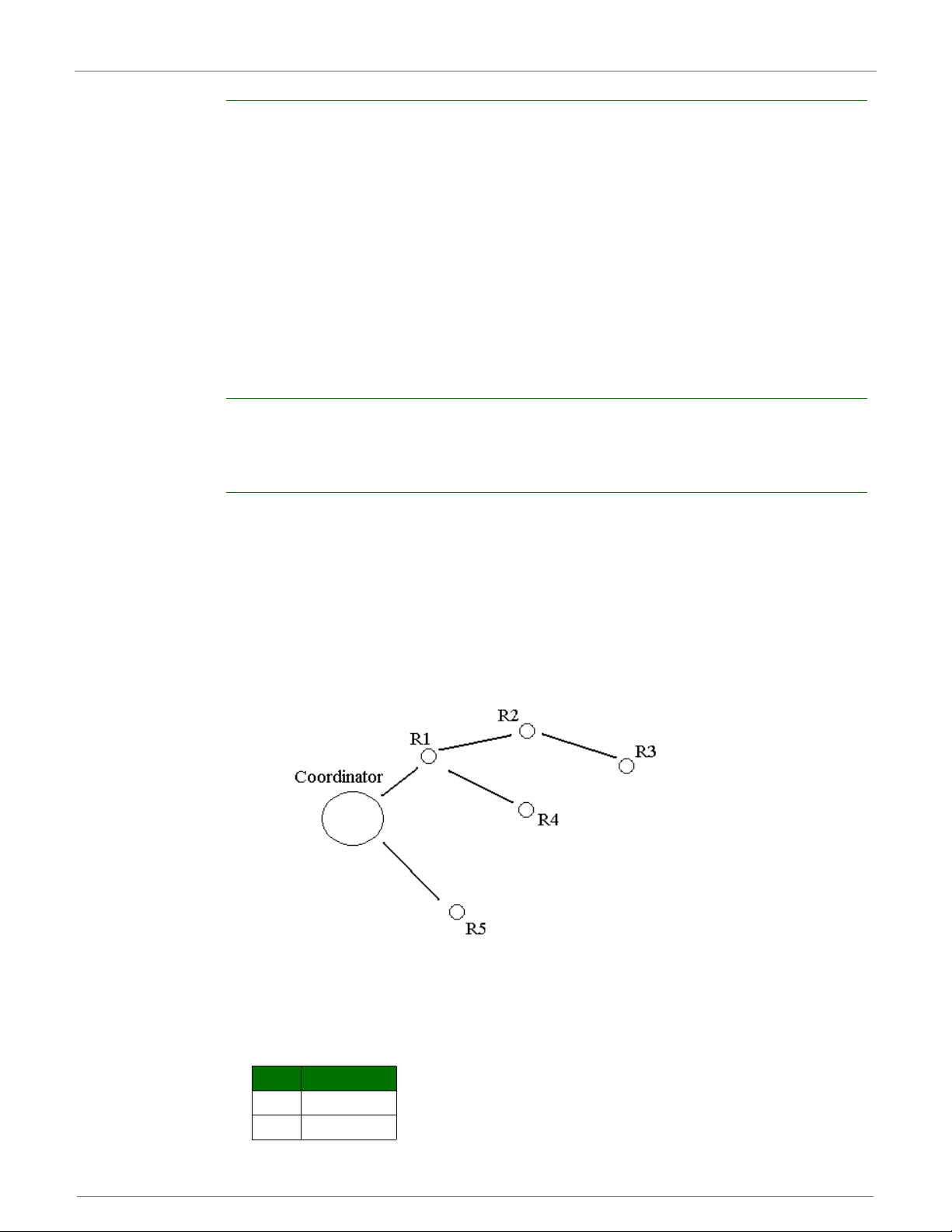
XBee®/XBee‐PRO®ZBRFModules
Acquiring Source Routes
Acquiring source routes requires the remote devices to send a unicast to a data collector (device
that sends many-to-one route request broadcasts). There are several ways to force remotes to
send route record transmissions.
1. If the application on remote devices periodically sends data to the data collector, each
transmission will force a route record to occur.
2. The data collector can issue a network discovery command (ND command) to force all XBee
devices to send a network discovery response. Each network discovery response will be prefaced
by a route record.
3. Periodic IO sampling can be enabled on remotes to force them to send data at a regular rate.
Each IO sample would be prefaced by a route record. (See chapter 8 for details.)
4. If the NI string of the remote device is known, the DN command can be issued with the NI
string of the remote in the payload. The remote device with a matching NI string would send a
route record and a DN response.
Storing Source Routes
When a data collector receives a route record, it sends it out the UAR T as a R oute Record Indicator
API frame (0xA1). T o use source routing, the application should receive these frames and store the
source route information.
Sending a Source Routed Transmission
To send a source routed transmission, the application should send a Create Source Route API
frame (0x21) to the XBee to create a source route in its internal source route table. After sending
the Create Source Route API frame, the application can send data transmission or remote
command request frames as needed to the same destination, or any destination in the source
route. Once data must be sent to a new destination (a destination not included in the last source
route), the application should first send a new Create Source Route API frame. The XBee can
buffer one source route that includes up to 10 hops (excluding source and destination).
For example, suppose a network exists with a coordinat or and 5 routers (R 1, R2, R3, R4, R 5) with
known source routes as shown below.
T o s end a source-routed pack et to R3, th e application must se nd a Create Source R oute API fr ame
(0x21) to the XBee, with a destination of R3, and 2 hops (R1 and R2). If the 64- bit address of R3
is 0x0013A200 404a1234 and the 16-bit addresses of R1, R2, and R3 are:
Device 16-bit address
R1 0xAABB
R2 0xCCDD
©2009DigiInternational,Inc. 54
Page 55

XBee®/XBee‐PRO®ZBRFModules
R3 0xEEFF
Then the Create Source Route API frame would be:
7E 0012 21 00 0013A200 404A1234 EEFF 00 02 CCDD AABB 5C
Where:
0x0012 - length
0x21 - API ID (create source route)
0x00 - frame ID (set to 0 always)
0x0013A200 404A1234 - 64-bit address of R3 (destination)
0xEEFF - 16-bit address of R3 (destination)
0x00 - Route options (set to 0)
0x02 - Number of intermediate devices in the source route
0xCCDD - Address of furthest device (1-hop from target)
0xAABB - Address of next-closer device
0x5C - Checksum (0xFF - SUM (all bytes after length))
Repairing Source Routes
It is possible in a network to have an existing source route fail (i.e. a device in the route moves or
goes down, etc.). If a device goes down in a source routed network, all ro utes that used the device
will be broken.
As mentioned previously, source routing must be used with many-to-one routing. (A device that
uses source routing must also send a periodic many-to-one broadcast in order to keep routes
fresh). If a source route is broken, remote devices must send in new route record transmissions to
the data collector to provide it with a new source route. This requires that remote devices
periodically send data transmissions into the data collector. See the earlier "Acquiring Source
Routes" section for details.
Retries and Acknowledgments
ZigBee includes acknowledgment packets at both the Mac and Application Support (APS) layers.
When data is transmitted to a remote device, it may traverse multiple hops to reach the
destination. As data is transmitted from one node to its neighbor, an acknowledgment packet
(Ack) is transmitted in the opposite direction to indicate that the transmission was successfully
received. If the Ack is not received, the transmitting device will retransmit the data, up to 4 times.
This Ack is called the Mac layer acknowledgment.
In addition, the device that originated the transmission expects to receive an ac knowledgment
packet (Ack) from the destination device. This Ack will traverse the same path that the data
traversed, but in the opposite direction. If the originator fails to receive this Ack, it will retransmit
the data, up to 2 times until an Ack is received. This Ack is called the ZigBee APS layer
acknowledgment.
Refer to the ZigBee specification for more details.
Encrypted Transmissions
Encrypted transmissions are routed similar to non-encrypted transmissions with one exception. As
an encrypted packet propagates from one device to another, each device decrypts the packet
using the network key, and authenticates the packet by verifying packet integrity. It then reencrypts the packet with its own source address and frame counter values, and sends the
message to the next hop. This process adds some overhead latency to unicast transmissions, but
it helps prevent replay attacks. See chapter 5 for details.
©2009DigiInternational,Inc. 55
Page 56

XBee®/XBee‐PRO®ZBRFModules
Maximum RF Payload Size
XBee ZB firmware includes a command (ATNP) that returns the maximum number of RF payload
bytes that can be sent in a unicast transmission. Querying the NP command, like most other
commands, returns a HEXADECIMAL value. This number will change based on whether security is
enabled or not. If security is enabled (EE command), the maximum number of RF payload bytes
decreases since security requires additional overhead.
After reading the NP value, the following conditions can affect the maxi mum number of data b ytes
in a single RF transmission:
• Broadcast transmissions can support 8 bytes more than unicast transmissions.
• If source routing is used, the 16-bit addresses in the source route are inserted into the RF
payload space. For example, if NP returns 84 bytes, and a source route must traverse 3 intermediate hops (3 16-bit addresses), the total number of bytes that can be sent in one RF
packet is 78.
• Enabling APS encryption (API tx option bit set) will reduce the number of payload byt es by 4.
Throughput
Throughput in a ZigBee network can vary by a number of variables, including: number of hops,
encryption enabled/disabled, sleeping end devices, failures/route discoveries. Our empirical
testing showed the following throughput performance in a robust operating environment (low
interference).
Data Throughput*
Configuration Data Throughput
1 hop, RR, SD 35kbps
1 hop, RR, SE 19kbps
1 hop, RE, SD 25kbps
1 hop, RE, SE 16kbps
1 hop, ER, SD 21kbps
1 hop, ER, SE 16kbps
4 hops, RR, SD 10kbps
4 hops, RR, SE 5kbps
RR = router to router,
RE = router to end device (non-sleeping),
ER = end device (non-sleeping) to router,
SD = security disabled,
SE = security enabled.
4 hops = 5 nodes total, 3 intermediate router nodes
* Data throughput measurements were made setting the serial interface rate to 115200 bps, and
measuring the time to send 100,000 bytes from source to destination. During the test, no route
discoveries or failures occurred.
ZDO Transmissions
ZigBee defines a ZigBee Device Objects layer (ZDO) that can provide device and service discovery
and network management capabilities. This layer is described below.
©2009DigiInternational,Inc. 56
Page 57

XBee®/XBee‐PRO®ZBRFModules
ZigBee Device Objects (ZDO)
The ZigBee Device Objects (ZDO) is supported to some extent on all ZigBee devices. The ZDO is
an endpoint that implements services described in the ZigBee Device Profile in the ZigBee
specification. Each service has an assigned cluster ID, and most service requests have an
associated response. The following table describes some common ZDO services.
Cluster Name Cluster ID Description
Network Address
Request
Active Endpoints
Request
LQI Request 0x0031 Request data from a neighbor table
Routing Table
Request
Network Address
Response
Cluster Name Cluster ID Description
LQI Response 0x8031 Response that includes neighbor
Routing Table
Response
Refer to the ZigBee specification for a detailed description of all ZigBee Device Profile services.
0x0000 Request a 16-bit address of the
0x0005 Request a list of endpoints from a
0x0032 Request to retrieve routing table
0x8000 Response that includes the 16-bit
0x8032 Response that includes routing
radio with a matching 64-bit
address (required parameter).
remote device.
of a remote device.
entries from a remote device.
address of a device.
table data from a remote device.
table entry data from a remote
device.
Sending a ZDO Command
To send a ZDO command, an explicit transmit API frame must be used and formatted correctly.
The source and destination endpoints must be set to 0, and the profile ID must be set to 0. The
cluster ID must be set to match the cluster ID of the appropriate service. For example, to send an
active endpoints request, the cluster ID must be set to 0x0005.
The first byte of payload in the API frame is an application sequence number (transaction
sequence number) that can be set to any single byte value. This same value will be used in the
first byte of the ZDO response. All remaining payload bytes must be set as required by the ZDO.
All multi-byte values must be sent in little endian byte order.
Receiving ZDO Commands and Responses
In XBee ZB firmware, ZDO commands can easily be sent using the API. In order to receive
incoming ZDO commands, receiver application addressing must be enabled with the AO command.
(See examples later in this section.) Not all incoming ZDO commands are passed up to the
application.
When a ZDO message is received on endpoint 0 and profile ID 0, the cluster ID indicates the type
of ZDO message that was received. The first byte of payload is generally a sequence number that
corresponds to a sequence number of a request. The remaining bytes are set as defined by the
ZDO. Similar to a ZDO request, all multi-byte values in the response are in little endian byte order.
Example 1: Send a ZDO LQI Request to read the neighbor table contents of a remote.
Looking at the ZigBee specification, the cluster ID for an LQI Request is 0x0031, and the payload
only requires a single byte (start index). This example will send an LQI request to a remote device
with a 64-bit address of 0x0013A200 40401234. The start index will be set to 0, and the
transaction sequence number will be set to 0x76
©2009DigiInternational,Inc. 57
Page 58

XBee®/XBee‐PRO®ZBRFModules
API Frame:
7E 0016 11 01 0013A200 40401234 FFFE 00 00 0031 0000 00 00 76 00 CE
0x0016 - length
0x11 - Explicit transmit request
0x01 - frame ID (set to a non-zero value to enable the transmit status message, or set to 0 to
disable)
0x0013A200 40401234 - 64-bit address of the remote
0xFFFE - 16-bit address of the remote (0xFFFE = unknown). Optionally, set to the 16-bit address
of the destination if known.
0x00 - Source endpoint
0x00 - Destination endpoint
0x0031 - Cluster ID (LQI Request, or Neighbor table request)
0x0000 - Profile ID (ZigBee Device Profile)
0x00 - Broadcast radius
0x00 - Tx Options
0x76 - Transaction sequence number
0x00 - Required payload for LQI request command
0xCE - Checksum (0xFF - SUM (all bytes after length))
Description:
This API frame sends a ZDO LQI request (neighbor table request) to a remote device to obtain
data from its neighbor table. Recall that the AO command must be set correctly on an API device
to enable the explicit API receive frames in order to receive the ZDO response.
Example 2: Send a ZDO Network Address Request to discover the 16-bit address of a remote.
Looking at the ZigBee specification, the cluster ID for a network Address Request is 0x0000, and
the payload only requires the following:
[64-bit address] + [Request Type] + [Start Index]
This example will send a Network Address Request as a broadcast t ransmi ssion to disco ver the 16-
bit address of the device with a 64-bit address of 0x0013A200 40401234. The request type and
start index will be set to 0, and the transaction sequence number will be set to 0x44
API Frame:
7E 001F 11 01 00000000 0000FFFF FFFE 00 00 0000 00 00 00 00 44 34124 040 00A213 00 00 00
33
0x001F - length
0x11 - Explicit transmit request
0x01 - frame ID (set to a non-zero value to enable the transmit status message, or set to 0 to
disable)
0x00000000 0000FFFF - 64-bit address for a broadcast transmission
0xFFFE - Set to this value for a broadcast transmission.
0x00 - Source endpoint
0x00 - Destination endpoint
0x0000 - Cluster ID (Network Address Request)
0x0000 - Profile ID (ZigBee Device Profile)
0x00 - Broadcast radius
0x00 - Tx Options
0x44 - Transaction sequence number
©2009DigiInternational,Inc. 58
Page 59

XBee®/XBee‐PRO®ZBRFModules
0x34124040 00A21300 00 00 - Required payload for Network Address Request command
0x33 - Checksum (0xFF - SUM (all byte s after length))
Description:
This API frame sends a broadcast ZDO Network Address Request to obtain the 16-bit address of a
device with a 64-bit address of 0x0013A200 40401234. Note the bytes for the 64-bit address were
inserted in little endian byte order. All multi-byte fields in the API payload of a ZDO command must
have their data inserted in little endian byte order. Also recall that the AO command must be set
correctly on an API device to enable the explicit API receive frames in order to receive the ZDO
response.
Transmission Timeouts
The ZigBee stack includes two kinds of transmission timeouts, depending on the nature of the
destination device. For destination devices such as routers whose receiver is always on, a unicast
timeout is used. The unicast timeout estimates a timeout based on the number of unicast hops the
packet should traverse to get data to the destination device. For transmissions destined for end
devices, the ZigBee stack uses an extended timeout that includes the unicast timeout (to route
data to the end device's parent), and it includes a timeout for the end device to finish sleeping,
wake, and poll the parent for data.
The ZigBee stack includes some prov isions for a device to detect if the destination is an end device
or not. The ZigBee stack uses the unicast timeout unless it knows the destination is an end device.
The XBee API includes a transmit options bit that can be set to specify if the extended timeout
should be used for a given transmission. If this bit is set , the exten ded ti me ou t wil l be u sed whe n
sending RF data to the specified destination. To improve routing reliability, applications should set
the extended timeout bit when sending data to end devices if:
• The application sends data to 10 or more remote devices, some of which are end devices,
AND
• The end devices may sleep longer than the unicast timeout
Equations for these timeouts are computed in the following sections.
Note: The timeouts in this section are worst-case timeouts and should be padded by a few
hundred milliseconds. These worst-case timeouts apply when an existing route breaks down (e.g.
intermediate hop or destination device moved).
Unicast Timeout
The unicast timeout is settable with the NH command. The actual unicast timeout is computed as
((50 * NH) + 100). The default NH value is 30 which equates to a 1.6 second timeout.
The unicast timeout includes 3 transmission attempts (1 attempt and 2 retries). The maximum
total timeout is about:
3 * ((50 * NH) + 100).
For example, if NH=30 (0x1E), the unicast timeout is ab out
3 * ((50 * 30) + 100), or
3 * (1500 + 100), or
3 * (1600), or
4800 ms, or
4.8 seconds.
Extended Timeout
The worst-case transmission timeout when sending data to an end device is somewhat larger than
when transmitting to a router or coordinator. As described later in chapter 6, RF data packets are
actually sent to the parent of the end device, who buffers the packet until the end device wakes to
receive it. The parent will buffer an RF data packet for up to (1.2 * SP) time.
©2009DigiInternational,Inc. 59
Page 60

XBee®/XBee‐PRO®ZBRFModules
To ensure the end device has adequate time to wake and receive the data, the extended
transmission timeout to an end device is:
(50 * NH) + (1.2 * SP)
This timeout includes the packet buffering timeout (1.2 * SP) and time to account for routing
through the mesh network (50 * NH).
If an acknowledgment is not received within this time, the sender will resend the transmission up
to two more times. With retries included, the longest transmission tim eo ut when sending data to
an end device is:
3 * ((50 * NH) + (1.2 * SP))
The SP value in both equations must be entere d in millisecond units. (The SP command setting
uses 10ms units and must be converted to milliseconds to be used in this equation.)
For example, suppose a router is configured with NH=30 (0 x1E) and SP=0x3E8 (10, 000 ms), and
that it is either trying to send data to one of its end device children, or to a remote end device. The
total extended timeout to the end device is about:
3 * ((50 * NH) + (1.2 * SP)), or
3 * (1500 + 12000), or
3 * (13500), or
40500 ms, or
40.5 seconds.
Transmission Examples
Example 1: Send a unicast API data transmission to the coordinator using 64-bit address 0, with payload "TxData".
API Frame:
7E 0014 10 01 00000000 00000000 FFFE 00 00 54 78 44 61 74 61 AB
Field Composition:
0x0014 - length
0x10 - API ID (tx data)
0x01 - frame ID (set greater than 0 to enable the tx-status response)
0x00000000 00000000 - 64-bit address of coordinator (ZB definition)
0xFFFE - Required 16-bit address if sending data to 64-bit address of 0.
0x00 - Broadcast radius (0 = max hops)
0x00 - Tx options
0x54 78 44 61 74 61 - ASCII representation of "TxData" string
0xAB - Checksum (0xFF - SUM (all bytes after lengt h))
Description:
This transmission sends the string "TxData" to the coordinator, without knowing the coordinator
device's 64-bit address. A 64-bit address of 0 is defined as the coordinator in ZB firmware. If the
coordinator's 64-bit address was known, the 64-bit address of 0 could be replaced with the
coordinator's 64-bit address, and the 16-bit address could be set to 0.
Example 2 - Send a broadcast API data transmission that all devices can receive (including sleeping end devices), with payload "TxData".
API Frame:
7E 0014 10 01 00000000 0000FFFF FFFE 00 00 54 78 44 61 74 61 AD
Field Composition:
0x0014 - length
0x10 - API ID (tx data)
©2009DigiInternational,Inc. 60
Page 61

XBee®/XBee‐PRO®ZBRFModules
0x01 - frame ID (set to a non-zero value to enable the tx-status response)
0x00000000 0000FFFF - Broadcast definition (including sleeping end devices
0xFFFE - Required 16-bit address to send broadcast transmission.
0x00 - Broadcast radius (0 = max hops)
0x00 - Tx options
0x54 78 44 61 74 61 - ASCII representation of "TxData" string
0xAD - Checksum (0xFF - SUM (all bytes after length))
Description:
This transmission sends the string "TxData" as a broadcast transmission. Since the destination
address is set to 0xFFFF, all devices, including sleeping end devices can receive this broadcast.
If receiver application addressing is enabled, the XBee will report all received data frames in the
explicit format (0x91) to indicate the source and destination endpoints, cluster ID, and profile ID
that each packet was received on. (Status messages like modem status and route record
indicators are not affected.)
To enable receiver application addressing, s et the AO command to 1 using the A T command frame
(0x08). Here's how to do this:
API Frame:
7E 0005 08 01 414F 01 65
Field Composition:
0x0005 - length
0x08 - API ID (at command)
0x01 - frame ID (set to a non-zero value to enable AT command response frames)
0x414F - ASCII representation of 'A','O' (the command being issued)
0x01 - Parameter value
0x65 - Checksum (0xFF - SUM (all byte s after length))
Description:
Setting AO=1 is required for the XBee to use the explicit receive API frame (0x91) when RF data
packets are received. This is required if the application needs indication of source or destination
endpoint, cluster ID, and/or profile ID values used in received ZigBee data packets. ZDO
messages can only be received if AO=1.
©2009DigiInternational,Inc. 61
Page 62

5.Security
ZigBee supports various levels of security that can be configured depending on the needs of the
application. Security provisions include:
The first half of this chapter describes various security features defined in the ZigBee-PRO
specification, while the last half illustrates how the XBee and XBee-PRO modules can be configured
to support these features
Security Modes
The ZigBee standard supports three security modes – residential, standard, and high security.
Residential security was first supported in the ZigB ee 2006 standard. This level of s ecurity requires
a network key be shared among devices. Standard security adds a number of optional security
enhancements over residential security, including an APS layer link key. High security adds entity
authentication, and a number of other features not widely supported.
XBee ZB modules primarily support standard security, although end devices that support
residential security can join and interoperate with standard security devices. The remainder of this
chapter focuses on material that is relevant to standard security.
• 128-bit AES encryption
• Two security keys that can be preconfigured or obtained during joining
• Support for a trust center
• Provisions to ensure message integrity, confidentiality, and authentication.
ZigBee Security Model
ZigBee security is applied to the Network and APS layers. Packets are encrypted with 128-bit AES
encryption. A network key and optional link key can be used to encrypt data. Only devices with the
same keys are able to communicate together in a network. Routers and end devices that will
communicate on a secure network must obtain the correct security keys.
Network Layer Security
The network key is used to encrypt the APS layer and application data. In addition to encrypting
application messages, network security is also applied to route request and reply messages, APS
commands, and ZDO commands. Network encryption is not applied to MAC layer transmissions
such as beacon transmissions, etc. If security is enabled in a network, all data packets will be
encrypted with the network key.
Packets are encrypted and authenticated using 128-bit AES. This is shown in the figure below.
©2009DigiInternational,Inc. 62
Page 63

XBee®/XBee‐PRO®ZBRFModules
Frame Counter
The network header of encrypted packets includes a 32-bit frame counter. Each device in the
network maintains a 32-bit frame counter that is incremented for every transmi ssion. In addi tion ,
devices track the last known 32-bit frame counter for each of its neighbors. If a device receives a
packet from a neighbor with a smaller frame counter than it has previously seen, the packet is
discarded. The frame counter is used to protect against replay attacks.
If the frame counter reaches a maximum value of 0xFFFFFFFF, it does not wrap to 0 and no more
transmissions can be sent. Due to the size of the frame counters, reaching the maximum value is
a very unlikely event for most applications. The following table shows the required time under
different conditions, for the frame counter to reach its maximum value.
Average Transmission Rate Time until 32-bit frame counter expires
1 / second 136 years
10 / second 13.6 years
T o clear the fr ame counters without compromisi ng security, the network key can be changed in the
network. When the network key is updated, the frame counters on all devices reset to 0. (See the
Network Key Updates section for details.)
Message Integrity Code
The network header, APS header, and application data are all authenticated with 128-bit AES. A
hash is performed on these fields and is appended as a 4-byte message integrity code (MIC) to the
end of the packet. The MIC allows receiving devices to ensure the message has not been changed.
The MIC provides message integrity in the ZigBee security model. If a device receives a packet
and the MIC does not match the device’s own hash of the data, the packet is dropped.
Network Layer Encryption and Decryption
Packets with network layer encryption are encrypted and decrypted by each hop in a route. When
a device receives a packet with network encryption, it decrypts the packet and authenti cates the
packet. If the device is not the destination, it then encrypts and authenticates the packet, using its
own frame counter and source address in the network header section.
©2009DigiInternational,Inc. 63
Page 64

XBee®/XBee‐PRO®ZBRFModules
Since network encryption is performed at each hop, packet latency is slightly longer in an
encrypted network than in a non-encrypted network. Also, security requires 18 bytes of overhead
to include a 32-bit frame counter, an 8-byte source address, 4-byte MIC, and 2 other bytes. This
reduces the number of payload bytes that can be sent in a data packet.
Network Key Updates
ZigBee supports a mechanism for changing the network key in a network. When the network key
is changed, the frame counters in all devices reset to 0.
APS Layer Security
APS layer security can be used to encrypt application data using a key that is shar ed between
source and destination devices. Where network layer security is applied to all data transmissions
and is decrypted and re-encrypted on a hop-by-hop basis, APS security is optional and provides
end-to-end security using an APS link key that only the source and destination device know. APS
security can be applied on a packet-by-packet basis. APS security cannot be applied to broadcast
transmissions.
If APS security is enabled, packets are encrypted and authenticated using 128-bit AES. This is
shown in the figure below:
Message integrity Code
If APS security is enabled, the APS header and data payload are authenticated with 128-bit AES. A
hash is performed on these fields and appended as a 4-byte message integrity code (MIC) to the
end of the packet. This MIC is different than the MIC appended by the network layer. The MIC
allows the destination device to ensure the message has not been changed. If the destination
device receives a packet and the MIC does not match the destination device’s own hash of the
data, the packet is dropped.
APS Link Keys
There are two kinds of APS link keys – trust center link keys and application link keys. A trust
center link key is established between a device and the trust center, where an application link key
is established between a device and another device in the network where neither device is the
trust center.
©2009DigiInternational,Inc. 64
Page 65

XBee®/XBee‐PRO®ZBRFModules
APS Layer Encryption and Decryption
Packets with APS layer encryption are encrypted at the source and only decrypted by the
destination. Since APS encryption requires a 5-byte header and a 4-byte MIC, the maximum data
payload is reduced by 9 bytes when APS encryption is used.
Network and APS Layer Encryption
Network and APS layer encryption can both be applied to data. The following figure demonstrates
the authentication and encryption performed on the final ZigBee packet when both are applied.
Trust Center
ZigBee defines a trust center device that is responsible for authenticating devices that join the
network. The trust center also manages link key distribution in the network.
Forming and Joining a Secure Network
The coordinator is responsible for selecting a network encryption key. This key can either be
preconfigured or randomly selected. In addition, the coordinator generally operates as a trust
center and must therefore select the trust cent er link key. The trust center link key can also be
preconfigured or randomly selected.
Devices that join the network must obtain the ne two r k k e y whe n th ey jo in . Wh e n a dev ice joi n s a
secure network, the network and link keys can be sent to the joining device. If the joining device
has a pre-configured trust center link key, the network key will be sent to the joining device
encrypted by the link key. Otherwise, if the joining device is not pre-configured with the link key,
the device could only join the network if the network key is sent unencrypted (“in the clear”). The
trust center must decide whether or not to send the network key unencrypted to joining devices
©2009DigiInternational,Inc. 65
Page 66

XBee®/XBee‐PRO®ZBRFModules
that are not pre-configured with the link key. Sending the network key unencrypted is not
recommended as it can open a security hole in the network. To maximize security, devices shou ld
be pre-configured with the correct link key.
Implementing Security on the XBee
If security is enabled in the XBee ZB firmware, devices acquire the network key when they join a
network. Data transmissions are always encrypted with the network key, and can optionally be
end-to-end encrypted with the APS link key. The following sections discuss the security settings
and options in the XBee ZB firmware.
Enabling Security
To enable security on a device, the EE command must be set to 1. If the EE command value is
changed and changes are applied (e.g. AC command), the XBee module will leave the network
(PAN ID and channel) it was operating on, and attempt to form or join a new network.
If EE is set to 1, all data transmissions will be encrypted with the network key. When security is
enabled, the maximum number of bytes in a single RF transmission will be reduced. See the NP
command for details.
Note: The EE command must be set the same on all devices in a network. Changes to the EE
command should be written to non-v olatile memor y (to be preserv ed through power cycle or reset
events) using the WR command.
Setting the Network Security Key
The coordinator must select the network security key for the network. The NK command (writeonly) is used to set the network key. If NK=0 (default), a random network key will be selected.
(This should suffice for most applications.) Otherwise, if NK is set to a non-zero v alue, the network
security key will use the value specified by NK. NK is only supported on the coordinator.
Routers and end devices with security enabled (A TEE=1) acquire the network key when they join a
network. They will receive the network key encrypted with the link key if they share a preconfigured link key with the coordinator. See the following section for details.
Setting the APS Trust Center Link Key
The coordinator must also select the trust center link key, using the KY command. If KY=0
(default), the coordinator will select a random trust center link key (not recommended).
Otherwise, if KY is set greater than 0, this value will be used as the pre-configured trust center link
key. KY is write-only and cannot be read.
Note: Application link keys (s ent between two de vices where neither device is the coordinator) are
not supported in ZB firmware at this time.
Random Trust Center Link Keys
If the coordinator selects a random trust center link key (KY=0, default), then it will allow devices
to join the network without having a pre-co nfi gured link k ey. However, this will cause the network
key to be sent unencrypted over-the-air to joining devices and is not recommended.
Pre-configured Trust Center Link Keys
If the coordinator uses a pre-configured link key (KY > 0), then the coordinator will not send the
network key unencrypted to joining devices. Only devices with the correct pre-c onfig ured li nk k ey
will be able to join and communicate on the network.
Enabling APS Encryption
APS encryption is an optional layer of security that uses the link key to encrypt the data payload.
Unlike network encryption that is decrypted and encrypted on a hop-by-hop basis, APS encryption
©2009DigiInternational,Inc. 66
Page 67

XBee®/XBee‐PRO®ZBRFModules
is only decrypted by the destination device. The XBee must be configured with security enabled
(EE set to 1) to use APS encryption.
APS encryption can be enabled in API firmware on a per-packet basis. To enable AP S encryption
for a given transmission, the "enable APS encryption" transmit options bit should be set in the API
transmit frame. Enabling APS encryption decreases the maximum payload size by 9 bytes.
Using a Trust Center
The EO command can be used to define the coordinator as a trust center. If the coordinator is a
trust center, it will be alerted to all new join attempts in the network. The trust center also has the
ability to update or change the network key on the network.
In ZB firmware, a secure network can be established with or without a trust center. Network and
APS layer encryption are supported if a trust center is used or not.
Updating the Network Key with a Trust Center
If the trust center has started a network and the NK value is changed, the coordinator will update
the network key on all devices in the network . (Changes to NK will not force the device to leave
the network.) The network will continue to ope rate on the sa me channel and PAN ID, but the
devices in the network will update their netw ork key, increment their network key sequence
number, and restore their frame counters to 0.
Updating the Network Key without a Trust Center
If the coordinator is not running as a trust center, the network reset command (NR1) can be used
to force all devices in the network to leave the current network and rejoin the network on another
channel. When devices leave and reform then network, the frame counters are reset to 0. This
approach will cause the coordinator to form a new network that the remaining devices should join.
Resetting the network in this manner will bring the coordinator and routers in the network down
for about 10 seconds, and will likely cause the 16-bit PAN ID and 16-bit addresses of the devices
to change.
XBee Security Examples
This section covers some sample XBee configur at ions to s upport differe nt securi ty modes. Sever a l
AT commands are listed with suggested parameter values. The notation in this section includes an
'=' sign to indicate what each command register should be set to - for example, EE=1. This is not
the correct notation for setting command values in the XBee. In AT command mode, each
command is issued with a leading 'AT' and no '=' sign - for example ATEE1. In the API, the two
byte command is used in the command field, and parameters are populated as binary values in the
parameter field.
Example 1: Forming a network with security (pre-configured link keys)
1. Start a coordinator with the following settings:
a. ID=2234 (arbitrarily selected)
b. EE=1
c. NK=0
d. KY=4455
e. WR (save networking parameters to preserve them through power cycle)
2. Configure one or more routers or end devices with the following settings:
a. ID=2234
b. EE=1
c. KY=4455
d. WR (save networking parameters to preserve them through power cycle)
©2009DigiInternational,Inc. 67
Page 68

XBee®/XBee‐PRO®ZBRFModules
3. Read the AI setting on th e coordi nator an d joining devices until they return 0 (formed or joined
a network).
In this example, EE, ID, and KY are set the same on all devices. After successfully joining the
secure network, all application data transmissions will be encrypted by the network key. Since NK
was set to 0 on the coordinator, a random network key was selected. And since the link key (KY)
was configured the same on all devices, to a non-zero value, the network key was sent encrypted
by the pre-configured link key (KY) when the devices joined.
Example 2: Forming a network with security (obtaining keys during joining)
1. Start a coordinator with the following settings:
a. ID=2235
b. EE=1
c. NK=0
d. KY=0
e. WR (save networking parameters to preserve them through power cycle)
2. Configure one or more routers or end devices with the following settings:
a. ID=2235
b. EE=1
c. KY=0
d. WR (save networking parameters to preserve them through power cycle)
3. Read the AI setting on the coordinator and joining devices until they re turn 0 (formed or join ed
a network).
In this example, EE, ID, and KY are set the same on all devices. Since NK was set to 0 on the
coordinator, a random network key was selected. And since KY was set to 0 on all devices, the
network key was sent unencrypted ("in the clear") when the devices joined. This approach
introduces a security vulnerability into the network and is not recommended.
©2009DigiInternational,Inc. 68
Page 69

6.NetworkCommissioningandDiagnostics
Network commissioning is the process whereby devices in a mesh network are discovered and
configured for operation. The XBee modules include several features to support device discovery
and configuration. In addition to configuring devices, a strategy must be developed to place
devices to ensure reliable routes.
To accommodate these requirements, the XBee modules include various features to aid in device
placement, configuration, and network diagnostics.
Device Configuration
XBee/XBee-PRO ZB modules can be configured locally through serial commands (AT or API), or
remotely through remote API comm ands. API devic es can send configur ation commands t o set or
read the configuration settings of any device in the network.
Device Placement
For a mesh network installation to be successful, the installer must be able to determine where to
place individual XBee devices to establish reliable links throughout the mesh network.
Link Testing
A good way to measure the performance of a mesh network is to send unicast data through the
network from one device to another to determine the success rate of many transmissions. To
simplify link testing, the modules support a loopback cluster ID (0x12) on the data endpoint
(0xE8). Any data sent to this cluster ID on the data endpoint will be transmitted back to the
sender. This is shown in the figure below:
The configuration steps to send data to the loopback cluster ID depend on the firmware type.
AT Firmware
To send data to the loopback cluster ID on the data endpoint of a remote device, set the CI
command value to 0x12. The SE and DE commands should be set to 0xE8 (default value). The DH
©2009DigiInternational,Inc. 69
Page 70

XBee®/XBee‐PRO®ZBRFModules
and DL commands should be set to the address of the remote (0 for t he coordin ator, or the 64-bit
address of the remote). After exiting command mode, any received serial characters will be
transmitted to the remote device, and returned to the sender.
API Firmware
Send an Explicit Addressing ZigBee Command API frame (0x11) using 0x12 as the cluster ID and
0xE8 as the source and destination endpoint. Data packets received by the remote will be echoed
back to the sender.
RSSI Indicators
It is possible to measure the received signal strength on a device using the DB command. DB
returns the RSSI value (measured in –dBm ) of the last receiv ed packet. Howev er, this number can
be misleading. The DB value only indicates the received signal strength of the last hop. If a
transmission spans multiple hops, the DB value provides no indication of the overall transmission
path, or the quality of the worst link – it only indicates the quality of the last link and shou ld be
used sparingly.
The DB value can be determine d in hardw are usi ng the RS SI/PWM module pin (pin 6). If the RSSI
PWM functionality is enabled (P0 command), when the modu le receive s data, the RSSI PWM is set
to a value based on the RSSI of the received packet. (Again, this value only indicates the quality of
the last hop.) This pin could potentially be connected to an LED to indicate if the link is stable or
not.
Device Discovery
Network Discovery
The network discovery command can be used to discover all Digi modules that have joined a
network. Issuing the ND command sends a broadcast node discovery command throughout the
network. All devices that receive the command will send a response that includes the device’s
addressing information, node identifier string (see NI command), and other relevant information.
This command is useful for generating a list of all module addresses in a network.
When a device receives the node discovery command, it waits a random time before sending its
own response. The maximum time delay is set on the ND sender with the NT command. The ND
originator includes its NT setting in the transmission to provide a delay window for all devices in
the network. Large networks may need to increase NT to improve network discovery reliability.
The default NT value is 0x3C (6 seconds).
ZDO Discovery
The ZigBee Device Profile includes provisions to discover devices in a network that are supported
on all ZigBee devices (including non-Digi products). These include the LQI Request (cluster ID
0x0031) and the Network Update Request (cluster ID 0x0038). The LQI Request can be used to
read the devices in the neighbor table of a remote device, and the Network Update Request can be
used to have a remote device do an active scan to discover all nearby ZigBee devices. Both of
these ZDO commands can be sent using the XBee Explicit API transmit frame (0x11). See the API
chapter for details. Refer to the ZigBee specification for formatting details of these two ZDO
frames.
Joining Announce
All ZigBee devices send a ZDO Device Announce broadcast transmission when the y join a ZigBee
network (ZDO cluster ID 0x0013). These frames will be sent out the XBee's UART as an Explicit Rx
Indicator API frame (0x91) if AO is set to 1. The device announce payload includes the following
information:
[ Sequence Number] + [16-bit address] + [64-bit address] + [Capability]
©2009DigiInternational,Inc. 70
Page 71

XBee®/XBee‐PRO®ZBRFModules
XBee
20
15
Push button
R
Associate
LED
A pushbutton and an LED can be connected to module pins 20 and 15 respectively to
support the commissioning pushbutton and associate LED functionalities.
The 16-bit and 64-bit addresses are received in little-endian byte order (LSB first). See the ZigBee
specification for details.
Commissioning Pushbutton and Associate LED
The XBee modules support a set of commissioning and LED behaviors to aid in device deployment
and commissioning. These include the commissioning pushbutton definitions and associate LED
behaviors. These features can be supported in hardware as shown below.
CommissioningPushbuttonandAssociateLEDFunctionalities
Commissioning Pushbutton
The commissioning pushbutton definitions pro vide a v ariety of simple functions to aid in deploying
devices in a network. The commissioning button functionality on pin 20 is enabled by setting the
D0 command to 1 (enabled by default).
If module is not joined to a net-
work
• Wakes an end device for
30 seconds
• Blinks a numeric error
code on the Associate pin
indicating the cause of
join failure (see section
6.4.2).
•N/A
1
2
Button
Presses
If module is joined to a network
• Wakes an end device for
30 seconds
• Sends a node identification broadcast transmission
• Sends a broadcast transmission to enable joining
on the coordinator and all
devices in the network for
1 minute. (If joining is
permanently enabled on a
device (NJ = 0xFF), this
action has no effect on
that device.)
©2009DigiInternational,Inc. 71
Page 72

XBee®/XBee‐PRO®ZBRFModules
Δt
Device Not Joined
Dev ice has joi ned a netw ork
Associate
The associate pin can indicate the joined status of a device . Once the device has joined a
network, the associate pin toggles state at a regular interval (Δt). The time can be set by
using the LT command.
If module is not joined to a net-
work
• Issues ATRE to restore
module parameters to
default values, including
ID and SC.
• The device attempts to
join a network based on
its ID and SC settings.
Presses
4
Button
If module is joined to a network
• Causes the device to leave
the PAN.
• Issues ATRE to restore
module parameters to
default values, including
ID and SC.
• The device attempts to
join a network based on
its ID and SC settings.
Button presses may be simulated in software using the ATCB command. ATCB should be issued
with a parameter set to the number of button presses to ex ecute. (e.g. sending ATCB1 will execu te
the action(s) associated with a single button press.)
The node identification frame is similar to the node discovery response frame – it contains the
device’s address, node identifier string (NI command), and other relevant data. All API devices
that receive the node identification frame send it out their UART as an API Node Identification
Indicator frame (0x95).
Associate LED
The Associate pin (pin 15) can provide indication of the device’s network status and diagnostics
information. To take advantage of these indications, an LED can be con nected to the Asso ciate pin
as shown in the figure above. The Associate LED functionality is enabled by setting the D5
command to 1 (enabled by default). If enabled, the Associate pin is configured as an output and
will behave as described in the following sections.
Joined Indication
The Associate pin indicates the network status of a device. If the module is not joined to a
network, the Associate pin is set high. On ce the module successfu lly joins a network, the Ass ociate
pin blinks at a regular time interval. This is shown in the following figure.
JoinedStatusofaDevice
The L T command defines the blink time of the Associate pin. If set to 0, the device uses the default
blink time (500ms for coordinator, 250ms for routers and end devices).
Diagnostics Support
The Associate pin works with the commissioning pushbutton to provide additional diagnostics
behaviors to aid in deploying and testing a network. If the commissioning push button is pressed
once, and the device has not joined a network, the Associate pin blinks a numeric error code to
indicate the cause of join failure. Th e number of blinks is equal to ( AI v alue – 0x20). For example,
if AI=0x22, 2 blinks occur.
If the commissioning push button is pressed once, and the device has joined a network, the device
transmits a broadcast node identification packet. If the Associate LE D fun ct ion ali t y is enabled (D5
command), a device that receives this transmission will blink its Associate pin rapidly for 1 second.
©2009DigiInternational,Inc. 72
Page 73

XBee®/XBee‐PRO®ZBRFModules
Associate
(D5 = 1
Device not joined)
A single commissioning button press when the device has not joined a network that
causes the associate pin to blink to indicate the AI Code where: AI = # blinks + 0x20.
In this example, AI = 0x22.
AD0/DIO0
Associate Pin
(D5 = 1)
AD0/DIO0 Pi n
(Remote Device)
A single button press on a remote device causes a broadcast node identification transmission
to be sent. All devices that receive this transmission blink their associate pin rapidly for one
second if the associate LED functionality is enabled. (D5 = 1)
The following figures demonstrate these behaviors.
AI=0x22
BroadcastNodeIdentificationTransmission
©2009DigiInternational,Inc. 73
Page 74

7.ManagingEndDevices
ZigBee end devices are intended to be battery-powered devices capable of sleeping for extended
periods of time. Since end devices may not be awake to receive RF data at a given time, routers
and coordinators are equipped with additional capabilities (including packet buffering and
extended transmission timeouts) to ensure reliable data delivery to end devices.
End Device Operation
When an end device joins a ZigBee network, it must find a router or coordinator device that is
allowing end devices to join. Once the end device joins a network, a parent-child relationship is
formed between the end device and the router or coordinator that allowed it to join. See chapter 3
for details.
When the end device is awake, it sends poll request messages to its parent. When the parent
receives a poll request, it chec ks a packet queue to see if it has any buffered messages fo r the end
device. It then sends a MAC layer acknowledgment back to the end device that indicates if it has
data to send to the end device or not.
If the end device receives the acknowledgment and finds that the parent has no data for it, the
end device can return to idle mode or sleep. Otherwise, it will remain awake to receive the data.
This polling mechanism allows the end device to enter idle mode and turn its receiver off when RF
data is not expected in order to reduce current consumption and conserve battery life.
The end device can only send data directly to its parent. If an end device must send a broadcast or
a unicast transmission to other devices in the network, it sends the message directly to its parent
and the parent performs any necessary route or address discoveries to route the packet to the
final destination.
Parent Operation
Each router or coordinator maintains a child table that contains the addresses of its end device
children. A router or coordinator that has unused entries in its child table is said to have end
device capacity, or the ability to allow new end devices to join. If the child table is completely filled
(such that the number of its end device children matches the number of child table entries), the
device cannot allow any more end devices to join to it.
©2009DigiInternational,Inc. 74
Page 75

XBee®/XBee‐PRO®ZBRFModules
Since the end device children are not guaranteed to be awake at a given time, the parent is
responsible for managing incoming data packets in behalf of its end device children. If a parent
receives an RF data transmission destined for one of its end device children, and if the parent has
enough unused buffer space, it will buffer the packet. The data packet will remain buffered until a
timeout expires, or until the end device sends a poll request to retrieve the data.
The parent can buffer one broadcast transmission for all of its end device children. When a
broadcast transmission is received and buffered, the parent sets a flag in its child table when each
child polls and retrieves the packet. Once all children have received the broadcast packet, the
buffered broadcast packet is discarded. If all children have not received a buffered broadcast
packet and a new broadcast is received, the old broadcast packet is discarded, the child table flags
are cleared, and the new broadcast packet is buffered for the end device children. This is
demonstrated in the figure below.
When an end device sends data to its parent that is destined for a remote device in the network,
the parent buffers the data packet until it can establish a route to the destination. The parent ma y
perform a route or 16-bit address discovery in behalf of its end device children. Once a route is
established, the parent sends the data transmission to the remote device.
End Device Poll Timeouts
To better support mobile end devices (end devices that can move around in a network), parent
router and coordinator devices have a poll timeout for each end device child. If an end device does
not send a poll request to its parent within the poll timeout, the parent will remove the end device
from its child table. This allows the child table on a router or coordinator to better accommodate
mobile end devices in the network.
Packet Buffer Usage
Packet buffer usage on a router or coordinator varies depending on the application. The following
activities can require use of packet buffers for up to several seconds:
• Route and address discoveries
• Application broadcast transmissions
• Stack broadcasts (e.g. ZDO "Device Announce" messages when devices join a network)
• Unicast transmissions (buffered until acknowledgment is received from destination or retries
exhausted)
• Unicast messages waiting for end device to wake.
Applications that use regular broadcasting or that require regular address or route discoveries will
use up a significant number of buffers, reducing the buffer availability for managing packets for
end device children. Applications should reduce the number of required application broadcasts,
and consider implementing an external address table or many-to-one and source routing if
necessary to improve routing efficiency.
©2009DigiInternational,Inc. 75
Page 76

XBee®/XBee‐PRO®ZBRFModules
Non-Parent Device Operation
Devices in the ZigBee network treat data transmissions to end devices differently than
transmissions to other routers and coordinators. Re call that when a unicast tran smission is sent, i f
a network acknowledgment is not received within a timeout, th e device re sends the transmission.
When transmitting data to remote coordinator or router devices, the transmission timeout is
relatively short since these devices are powered and responsive. However, since end devices may
sleep for some time, unicast transmissions to end devices use an extended timeout mechanism in
order to allow enough time for the end device to wake and receive the data transmission from its
parent.
If a non-parent device does not know the destination is an end device, it will use the standard
unicast timeout for the transmission. However, provisions exist in the Ember ZigBee stack for the
parent to inform the message sender that the destination is an end device. Once the sender
discovers the destination device is an end device, future transmissions will use the extended
timeout. See the XBee Router / Coordinator Configuration section in this chapter for details.
XBee End Device Configuration
XBee end devices support two different sleep modes:
•Pin Sleep
•Cyclic Sleep.
Pin sleep allows an external microcontroller to determine when the XBee should sleep and when it
should wake by controlling the Sleep_RQ pin. In contrast, cyclic sleep allows the sleep period and
wake times to be configured through the use of AT commands. The sleep mode is configurable
with the SM command.
In both pin and cyclic sleep modes, XBee end devices poll their parent every 100ms while they are
awake to retrieve buffered data. When a poll request has been sent, the end device enables the
receiver until an acknowledgment is received from the parent. (It generally takes less than 10ms
from the time the poll request is sent until the acknowledgment is received.) The acknowledgment
indicates if the parent has buffered data for the end device child or not. If the acknowledgment
indicates the parent has pending data, the end device will leave the receiver on to receive t he
data. Otherwise, the end device will turn off the receiver and enter idle mode (until the next poll
request is sent) to reduce current consumption (and improve battery life).
Once the module enters sleep mode, th e On/Sleep pin ( pin 13) is de- asserted (l ow) to indicate th e
module is entering sleep mode. If CTS hardware flow control is enabled (D7 command), the CTS
pin (pin 12) is de-asserted (high) when entering sleep to indicate that serial data should not be
sent to the module. The module will not respond to serial or RF data when it is sleeping.
Applications that must communicate serially to sleeping end devices are encouraged to observe
CTS flow control.
When the XBee wakes from sleep, the On/Sleep pin is asserted (high), and if flow control i s
enabled, the CTS pin is also asserted (l ow). If the modu le ha s not joine d a network, it will s can all
SC channels after waking to try and find a valid network to join.
Pin Sleep
Pin sleep allows the module to sleep and wake according to the state of the Sleep_RQ pin (pin 9).
Pin sleep mode is enabled by setting the SM command to 1.
When Sleep_RQ is asserted (high), the module wi ll finish any transmit or receive operations and
enter a low power state. For example, if the module has not joined a network and Sleep_RQ is
asserted (high), the module will sleep once the current join attempt com pletes (i.e. when sc anning
for a valid network completes). The module will wake from pin slee p when the Sleep_RQ pin is deasserted (low).
©2009DigiInternational,Inc. 76
Page 77

XBee®/XBee‐PRO®ZBRFModules
In the figure above, t1, t2, and t3 represent the following events:
•T1 - Time when Sleep_RQ is asserted (high)
• T2 - Time when the XBee enters sleep (CTS state change only if hardware flow control is
enabled)
• T3 - Time when Sleep_RQ is de-asserted (low) and the module wakes.
The time between T1 and T2 varies depending on the state of the module. In the worst case
scenario, if the end device is trying to join a network, or if it is waiting for an acknowledgment
from a data transmission, the delay could be up to a few seconds.
When the XBee is awake and is joined to a network, it sends a poll request to its parent to see if
the parent has any buffered data for it. The end device will continue to send poll requests every
100ms while it is awake.
©2009DigiInternational,Inc. 77
Page 78

XBee®/XBee‐PRO®ZBRFModules
DemonstrationofPinSleep
Parent and remote devices must be configured to buffer data correctly and to utilize adequate
transmission timeouts. See the XBee R outer / Coordina tor Configurat ion section in this chapte r for
details.
Cyclic Sleep
Cyclic sleep allows the module to sleep for a specified time and wake for a short time to poll its
parent for any buffered data messages before returning to sleep again. Cyclic sleep mode is
enabled by setting the SM command to 4 or 5. SM5 is a slight variation of SM4 that allows the
module to be woken prematurely by asserting the Sleep_RQ pin (pin 9). In SM5, the XBee can
wake after the sleep period expires, or if a high-to-low transition occurs on the Sleep_RQ pin.
Setting SM to 4 disables the pin wake option.
In cyclic sleep, the module sleeps for a specified time, and then wakes and sends a poll request to
its parent to discover if the parent has any pending data for the end device. If the parent has
buffered data for the end device, or if serial data is received, the XBee will remain awake for a
time. Otherwise, it will enter sleep mode immediately.
The On/Sleep line is asserted (high) when the module wakes, and is de-asserted (low) when the
module sleeps. If hardware flow control is enabled (D7 command), the CTS pin will assert (low)
when the module wakes and can receive serial data, and de-assert (high) when the module sleeps.
©2009DigiInternational,Inc. 78
Page 79

XBee®/XBee‐PRO®ZBRFModules
In the figure above, t1, t2, and t3 represent the following events:
• T1 - Time when the module wakes from cyclic sleep
• T2 - Time when the module returns to sleep
• T3 - Later time when the module wakes from cyclic sleep.
The wake time and sleep time are configurable with software commands as described in the
sections below.
Wake Time (Until Sleep)
In cyclic sleep mode (SM=4 or 5), if serial or RF data is received, the module will start a sleep
timer (time until sleep). Any data received serially or over the RF link will restart the timer. The
sleep timer value is settable with the ST command. While the module is awake, it will send poll
request transmissions every 100ms to check its parent for buffered data messages. The module
returns to sleep when the sleep timer expires, or if the SI command is sent to it. The following
image shows this behavior.
©2009DigiInternational,Inc. 79
Page 80

XBee®/XBee‐PRO®ZBRFModules
DIN
A cyclic sleep end device enters sleep mode when no serial or RF data is received for ST time .
ST = Time Awake
On/Sleep
Legend
On/Sleep
Transmitting Poll
Request
Sleep Period
The sleep period is configured based on the SP, SN, and SO commands. The following table lists
the behavior of these commands.
Command Range Description
SP
SN
0x20 - 0xAF0 (x 10 ms)
(320 - 28,000 ms)
1 - 0xFFFF
Configures the sleep period of the module.
Configures the number of sleep periods
multiplier.
Defines options for sleep mode behavior.
SO
0 - 0xFF
0x02 - Always wake for full ST time
0x04 - Enable extended sleep (sleep for full
(SP * SN) time)
The XBee module supports both a short cyclic sleep and an extended cyclic sleep that make use of
these commands. These two modes allow the sleep period to be configured according to the
application requirements.
Short Cyclic Sleep
In short cyclic sleep mode, the sleep behavior of the module is defined by the SP and SN
commands, and the SO command must be set to 0x00 (default) or 0x02. In short cyclic sleep
mode, the SP command defines the sleep period and is settable up to 28 seconds. When the XBee
enters short cyclic sleep, it remains in a low power state until the SP time has expired.
After the sleep period expires, the XBee sends a poll request transmission to its parent to
determine if its parent has any buffered data waiting for the end device. Since router and
coordinator devices can buffer data for end device children up to 30 seconds, the SP range (up to
28 seconds) allows the end device to poll regularly enough to receive buffered data. If the parent
has data for the end device, the end device will start its sleep timer (ST) and continue polling
every 100ms to receive data. If the end device wakes and finds that its parent has no data for it,
the end device can return to sleep immediately.
The SN command can be used to control when the On/Sleep line is asserted (high). If SN is set to
1 (default), the On/Sleep line will be set high each time the XBee wakes from sleep. Otherwise, if
SN is greater than 1, the On/Sleep line will only be set high if RF data is received, or after SN wake
cycles occur . This allows an external device to remain powered off until RF data is received, or until
a number of sleep periods have expired (SN sleep periods). This mechanism allows the XBee to
wake at regular intervals to poll its parent for data without waking an external device for an
extended time (SP * SN time). This is shown in the figure below.
©2009DigiInternational,Inc. 80
Page 81

XBee®/XBee‐PRO®ZBRFModules
On/Sleep
Δt = SP
Δt = SP * SN
(SN = 1)
Setting SN > 1 allows the XBee to silently poll for data without asserting On /Sleep. If RF data is received
when polling, On/Sleep will immediately assert .
Transmitting poll reques t to parent
Δt = SP
Sleep_RQ
Transmitting Poll
Reques t
Legend
Δt = SP * SN
On/Sleep
(SN = 3)
Transmitting poll request to parent
Note: SP controls the packet buffer time on routers and coordinators. SP should be set on all
router and coordinator devices to match the longest end device SP ti me. See the XBee Router /
Coordinator Configuration section for details.
Extended Cyclic Sleep
In extended cyclic sleep operation, an end device can sleep for a multiple of SP time which can
extend the sleep time up to several days. The sleep period is configured using the SP and SN
commands. The total sleep period is equal to (SP * SN) where SP is measured in 10ms units . The
SO command must be set correctly to enable extended sleep.
Since routers and coordinators can only buffer incoming RF data for their end device children for
up to 30 seconds, if an end device sleeps longer than 30 seconds, devices in the network need
some indication when an end device is awake before they can send data to it. End devices that use
extended cyclic sleep should send a transmission (such as an IO sample) when they wake to
inform other devices that they are awake and can receive data. It is recommended that extended
sleep end devices set SO to wake for the full ST time in order to provide other devices with enough
time to send messages to the end device.
Similar to short cyclic sleep, end devices running in this mode will return to sleep when the sleep
timer expires, or when the SI command is received.
Transmitting RF Data
An end device may transmit data when it wakes from sleep and has joined a network. End devices
transmit directly to their p arent and then wait for an acknowledgment to be received. The parent
will perform any required address and route discoveries to help ensure the packet reaches the
intended destination before reporting the transmission status to the end device.
Receiving RF Data
After waking from sleep, an end device sends a poll reques t to its parent to determine if the parent
has any buffered data for it. In pin sleep mode, the end device polls every 100ms while the
Sleep_RQ pin is de-asserted (low). In cyclic sleep mode, the end device will only poll once before
returning to sleep unless the sleep timer (ST) is start ed (serial or RF data i s received) . If the sleep
timer is started, the end device will continue to poll every 100ms until the sleep timer expires.
©2009DigiInternational,Inc. 81
Page 82

XBee®/XBee‐PRO®ZBRFModules
The XBee ZB 2x6x firmware includes an adaptive polling enhancement where, if an end device
receives RF data from its parent, it sends another poll after a very short delay to check for more
data. The end device continues to poll at a faster rate as long as it receives data from its parent.
This feature greatly improves data throughput to end devices. When th e end device no longer
receives data from its parent, it resumes polling every 100ms.
IO Sampling
End devices can be configured to send one or more IO samples when they wake from sleep. To
enable IO sampling on an end device, the IR command must be set to a non-zero value, and at
least one analog or digital IO pin must be enabled for sampling (D0 - D9, P0-P 2 commands). If IO
sampling is enabled, an end device sends an IO sample when it wakes and starts the ST timer. It
will continue sampling at the IR rate until the sleep timer (ST) has expired. See chapter 8 for
details.
Waking End Devices with the Commissioning Pushbutton
If the commissioning pushbutton functionality is enabled (D0 command), a high-to-low transition
on the AD0/DIO0 pin (pin 20) will cause an end device to wake for 30 seconds. See the
Commissioning Pushbutton section in chapter 7 for details.
Parent Verification
Since an end device relies on its parent to maintain connectivity with other dev ices in the network,
XBee end devices include provisions to verify its connection with its parent. End devices monitor
their link with their parent when sending poll messages and after a power cycle or reset event as
described below.
When an end device wakes from sleep, it sends a poll request to its parent. In cyclic sleep, if RF or
serial data is not received and the sleep timer is not started, the end device polls one time and
returns to sleep for another sleep period. Otherwise, the end device continues polling every
100ms. If the parent does not send an acknowledgment response to three consecutive poll
request transmissions, the end device assumes the parent is out of range, and attempts to find a
new parent.
After a power-up or reset event, the end device does an orphan scan to locate its parent. If the
parent does not send a response to the orphan scan, the end device attempts to find a new
parent.
Rejoining
Once all devices have joined a ZigBee network, the permit-joining attribute should be disabled
such that new devices are no longer allowed to join the network. Permit-joining can be enabled
later as needed for short times. This provides some protection in preventing other devices from
joining a live network.
If an end device cannot communicate with its parent, the end device must be able to join a new
parent to maintain network connectivity. However, if permit-joining is disabled in the network, the
end device will not find a device that is allowing new joins.
To overcome this problem, ZigBee supports rejoining, where an end device can obtain a new
parent in the same network even if joining is not enabled. When an end device joins using
rejoining, it performs a PAN ID scan to discover nearby networks. If a network is discovered that
has the same 64-bit PAN ID as the end device, it will join the network by sending a rejoin request
to one of the discovered devices. The device that receives the rejoin request will send a rejoin
response if it can allow the device to join the network (i.e. child table not full). The rejoin
mechanism can be used to allow a device to join the same network even if permit-joining is
disabled.
To enable rejoining, NJ should be set less than 0xFF on the device that will join. If NJ < 0xFF, the
device assumes the network is not allowing joining and first tries to join a network using rejoining.
If multiple rejoining attempts fail, or if NJ=0xFF, the device will attempt to join using association.
©2009DigiInternational,Inc. 82
Page 83

XBee®/XBee‐PRO®ZBRFModules
XBee Router/Coordinator Configuration
XBee routers and coordinators may require some configuration to ensure the following are set
correctly:
• RF packet buffering timeout
•Child poll timeout
• Transmission timeout.
The value of these timeouts depends on the sleep time used by the end devices. Each of these
timeouts are discussed below.
RF Packet Buffering Timeout
When a router or coordinator receives an RF data packet intended for one of its end device
children, it buffers the packet until the end device wakes and polls for the data, or until a packet
buffering timeout occurs. This timeout is settable using the SP command. The actual timeout is
(1.2 * SP), with a minimum timeout of 1.2 seconds and a maximum of 30 seconds. Since the
packet buffering timeout is set slightly larger than the SP setting, SP should be set the same on
routers and coordinators as it is on cyclic sleep end devices. For pin sleep devices, SP should be
set as long as the pin sleep device can sleep, up to 30 seconds.
Note: In pin sleep and extended cyclic slee p, end device s can sleep longer t han 30 seconds. If end
devices sleep longer than 30 seconds, parent and non-parent devices must know when the end
device is awake in order to reliably send data. F or applications that require sleeping longer than 30
seconds, end devices should transmit an IO sample or other data when they wake to alert other
devices that they can send data to the end device.
Child Poll Timeout
Router and coordinator devices maintain a timestamp for each end device child indicating when
the end device sent its last poll request to check for buffered data packets. If an end device does
not send a poll request to its parent for a certain period of time, the parent will assume the end
device has moved out of range and will remove the end device from its child table. This allows
routers and coordinators to be responsive to changing network conditions. The NC command can
be issued at any time to read the number of remaining (unused) child table entries on a router or
coordinator.
The child poll timeout is settable with the SP and SN commands. SP and SN should be set such
that SP * SN matches the longest expected sle ep time of any end devices in the network. The
actual timeout is calculated as (3 * SP * SN), with a minimum of 5 seconds. For networks
consisting of pin sleep end devices, the SP and SN values on the coordinator and routers should be
set such that SP * SN matches the longest expected sleep period of any pin sleep device. The 3
multiplier ensures the end device will not be removed unless 3 sleep cycl es pass without receivin g
a poll request. The poll timeout is settable up to a couple of months.
Transmission Timeout
As mentioned in chapter 4, when sending RF data to a remot e router, since routers are always on,
the timeout is based on the number of hops the transmission may traverse. This timeout it
settable using the NH command. (See chapter 4 for details.)
Since end devices may sleep for lengthy periods of time, the transmission timeout to end devices
also includes some allowance for the sleep period of the end device. When sending data to a
remote end device, the transmission timeout is calculated using the SP and NH commands. If the
timeout occurs and an acknowledgment has not been received, the source device will resend the
transmission until an acknowledgment is received, up to two more times.
The transmission timeout per attempt is:
3 * ((unicast router timeout) + (end device sleep time)), or
3 * ((50 * NH) + (1.2 * SP)), where SP is measured in 10ms units.
©2009DigiInternational,Inc. 83
Page 84

XBee®/XBee‐PRO®ZBRFModules
Putting it all Together
Short Sleep Periods
Pin and cyclic sleep devices that sleep less than 30 sec onds can receiv e data transmissions at any
time since their parent device(s) will be able to buffer data long enough for the end devices to
wake and poll to receive the data. SP should be set the same on all devices in the network. If end
devices in a network have more than one SP setting, SP on the routers and coordinators should be
set to match the largest SP setting of any end device. This will ensure the RF packet buffering, poll
timeout, and transmission timeouts are set correctly.
Extended Sleep Periods
Pin and cyclic sleep devices that might sleep longer than 30 seconds cannot receive data
transmissions reliably unless certain design approaches are taken. Specifically, the end devices
should use IO sampling or another mechanism to transmit data when they wake to inform the
network they can receive data. SP and SN should be set on routers and coordinators such that (SP
* SN) matches the longest expected sleep time. This configures the poll timeout so end devices
are not expired from the child table unless a poll request is not received for 3 consecutive sleep
periods.
As a general rule of thumb, SP and SN should be set the same on all devices in almost all cases.
Sleep Examples
This section covers some sample X Bee configur ations to su pport different sleep mode s. Sever al AT
commands are listed with suggested parameter values. The notation in this section includes an '='
sign to indicate what each command register should be set to - for example, SM=4. This is not the
correct notation for setting command values in the XBee. In AT command mode, each command is
issued with a leading 'A T' and no '=' sign - for example ATSM4. In the API, the two byte command
is used in the command field, and parameters are populated as binary values in the parameter
field.
Example 1
Configure a device to sleep for 20 seconds, but set SN such that the On/Sleep line will
remain de-asserted for up to 1 minute.
The following settings should be configured on the end device.
SM = 4 (cyclic sleep) or 5 (cyclic sleep, pin wake)
SP = 0x7D0 (2000 decimal). This causes the end device to sleep for 20 seconds since SP is
measured in units of 10ms.
SN = 3. (With this setting, the On/Sleep pin will assert once every 3 sleep cycles, or when RF data
is received)
SO = 0
All router and coordinator devices on the network should set SP to match SP on the end device.
This ensures that RF packet buffering times and transmission timeouts will be set correctly.
Since the end device wakes after each sleep period (A TSP), the SN command can be set to 1 on all
routers and the coordinator.
Example 2
Configure an end device to sleep for 20 seconds, send 4 IO samples in 2 seconds, and
return to sleep.
Since SP is measured in 10ms units, and ST and IR are measured in 1ms units, configure an end
device with the following settings:
SM = 4 (cyclic sleep) or 5 (cyclic sleep, pin wake)
SP = 0x7D0 (2000 decimal). This causes the end device to sleep for 20 seconds.
©2009DigiInternational,Inc. 84
Page 85

XBee®/XBee‐PRO®ZBRFModules
SN = 1
SO = 0
ST = 0x7D0 (2000 decimal). This sets the sleep timer to 2 seconds.
IR = 0x258 (600 decimal). Set IR to a value greater than (2 seconds / 4) to get 4 samples in 2
seconds. The end device sends an IO sample at the IR rate until the sleep timer has expired.
At least one analog or digital IO line must be enabled for IO sampling to work. To enable pin 19
(AD1/DIO1) as a digital input line, the following must be set:
D1 = 3
All router and coordinator devices on the network should set SP to match SP on the end device.
This ensures that RF packet buffering times and transmission timeouts will be set correctly.
Example 3
Configure a device for extended sleep: to sleep for 4 minutes.
SP and SN must be set such that SP * SN = 4 minutes. Since SP is measured in 10ms units, the
following settings can be used to obtain 4 minute sleep.
SM = 4 (cyclic sleep) or 5 (cyclic sleep, pin wake)
SP = 0x7D0 (2000 decimal, or 20 seconds)
SN = 0x0B (12 decimal)
SO = 0x04 (enable extended sleep)
With these settings, the modu le will sleep for SP * SN time, or (20 se conds * 12) = 240 seconds =
4 minutes.
For best results, the end device should send a transmission when it wakes to inform the
coordinator (or network) when it wakes. It should also remain awake for a short time to allow
devices to send data to it. The following are recommended settings.
ST = 0x7D0 (2 second wake time)
SO = 0x06 (enable extended sleep and wake for ST time)
IR = 0x800 (send 1 IO sample after waking). At least one analog or digital IO sample should be
enabled for IO sampling.
With these settings, the end device will wake after 4 minutes and send 1 IO sample. It will then
remain awake for 2 seconds before returning to sleep.
SP and SN should be set to the same values on all routers and coordinators that could allow the
end device to join. This will ensure the parent does not timeout the end device from its child table
too quickly.
The SI command can optionally be sent to the end device to cause it to sleep before the sleep
timer expires.
©2009DigiInternational,Inc. 85
Page 86

8.XBeeAnalogandDigitalIOLines
XBee ZB firmware supports a number of analog and digital IO pins that are configured through
software commands. Analog and digital IO lines can be set or queried. The following table lists the
configurable IO pins and the corresponding configuration commands.
Module Pin Names Module Pin Numbers Configuration Command
CD/DIO12 4 P2
PWM0/RSSIM/DIO10 6 P0
PWM/DIO11 7 P1
DIO4 11 D4
CTS/DIO7 12 D7
ASSOC/DIO5 15 D5
RTS/DIO6 16 D6
AD3/DIO3 17 D3
AD2/DIO2 18 D2
AD1/DIO1 19 DI
AD0/DIO0 20 D0
IO Configuration
To enable an analog or digital IO function on one or more XBee module pin(s), the appropriate
configuration command must be issued with the correct parameter. After issuing the configuration
command, changes must be applied on the module for the IO settings to take effect.
Pin Command Parameter Description
0 Unmonitored digital input
1 Reserved for pin-specific alternate functionalities
2 Analog input, single ended (A/D pins only)
3 Digital input, monitored
4 Digital output, default low
5 Digital output, default high
6-9 Alternate functionalities, where applicable
Pull-up resistors can be set for each digital input line using the PR command. The PR value updates
the state of all pull-up resistors.
IO Sampling
The XBee ZB modules have the ability to monitor and sample the analog and digital IO lines. IO
samples can be read locally or transmitted to a remote device to provide indication of the current
IO line states. (Only API firmware devices can send remote IO sample data out their UART.)
There are three ways to obtain IO samples, either locally or remotely:
©2009DigiInternational,Inc. 86
Page 87

XBee®/XBee‐PRO®ZBRFModules
•Queried Sampling
•Periodic Sampling
• Change Detection Sampling.
IO sample data is formatted as shown in the table below
Bytes Name Description
1 Sample Sets Number of sample sets in the packet. (Always set to 1.)
2 Digital Channel Mask
1 Analog Channel Mask
Variable Sampled Data Set
Indicates which digital IO lines have sampling enabled. Each bit corresponds to one
digital IO line on the module.
• bit 0 = AD0/DIO0
• bit 1 = AD1/DIO1
• bit 2 = AD2/DIO2
• bit 3 = AD3/DIO3
• bit 4 = DIO4
• bit 5 = ASSOC/DIO5
•bit 6 = RTS/DIO6
•bit 7 = CTS/GPIO7
• bit 8 = N/A
• bit 9 = N/A
• bit 10 = RSSI/DIO10
• bit 11 = PWM/DIO11
• bit 12 = CD/DIO12
For example, a digital channel mask of 0x002F means DIO0,1,2,3, and 5 are enabled
as digital IO.
Indicates which lines have analog inputs enabled f or samp ling. Ea ch bit in th e ana log
channel mask corresponds to one analog input channel.
• bit 0 = AD0/DIO0
• bit 1 = AD1/DIO1
• bit 2 = AD2/DIO2
• bit 3 = AD3/DIO3
• bit 7 = Supply Voltage
A sample set consisting of 1 sample for each enabled ADC and/or DIO channel,
which has voltage inputs of 1 143.75 and 342.1875mV .
If any digital IO lines are enabled, the first two bytes of the data set indicate the stat e
of all enabled digital IO. Only digital channels that are enabled in the Digital Channel
Mask bytes have any meaning in the sample set. If no digital IO are enabled on the
device, these 2 bytes will be omitted.
Following the digital IO data (if any), each enabled analog channel will return 2 byte s.
The data starts with AIN0 and continues sequentially for each enabled analog input
channel up to AIN3, and the supply voltage (if enabled) at the end.
The sampled data set will include 2 bytes of digital IO data only if one or more IO lines on the
device are configured as digital IO. If no pins are configured as digital IO, these 2 bytes will be
omitted.
The digital IO data is only relevant if the same bit is enabled in the digital IO mask.
Analog samples are returned as 10-bit values. The analog reading is scaled such that 0x0000
represents 0V, and 0x3FF = 1.2V. (The analog inputs on the module cannot read more than 1.2V.)
Analog samples are returned in order starting with AIN0 and finishing with AIN3, and the supply
voltage. Only enabled analog input channels return data as shown in the figure below.
To convert the A/D reading to mV, do the following:
AD(mV) = (A/D reading * 1200mV) / 1024
©2009DigiInternational,Inc. 87
Page 88

XBee®/XBee‐PRO®ZBRFModules
The reading in the sample frame represents voltage inputs of 1143.75 and 342.1875mV for AD0
and AD1 respectively.
Queried Sampling
The IS command can be sent to a device locally, or to a remote device using the API remote
command frame (see chapter 8 for details). When the IS command is sent, the receiving device
samples all enabled digital IO and analog input channels and returns an IO sample. If IS is sent
locally, the IO sample is sent out the UART. If the IS command was received as a remote
command, the IO sample is sent over-the-air to the device that sent the IS command.
If the IS command is issued in AT firmware, the module returns a carriage return-delimited list
containing the above-listed fields. The API firmware returns an AT command response packet with
the IO data included in the command data portion of the response frame.
The following table shows an example of the fields in an IS response.
0x01 [1 sample set]
0x0C0C [Digital Inputs: DIO 2, 3, 10, 11 low]
0x03 [Analog Inputs: A/D 0, 1]
0x0408 [Digital input states: DIO 3, 10 high, DIO 2, 11 low]
0x03D0 [Analog input ADIO 0= 0x3D0]
0x0124 [Analog input ADIO 1=0x120]
Example Sample AT Response
Periodic IO Sampling
Change Detection Sampling
RSSI PWM
Periodic sampling allows an XBee/XBee-PRO module to take an IO sample and transmit it to a
remote device at a periodic rate. The periodic sample rate is set by the IR command. If IR is set to
0, periodic sampling is disabled. For all other values of IR, data will be sampled after IR
milliseconds have elapsed and transmitted to a remote device. The DH and DL commands
determine the destination address of the IO samples. DH and DL can be set to 0 to transmit to the
coordinator, or to the 64-bit address of the remote device (SH and SL). Only devices running API
firmware can send IO data samples out their UART. Devices running AT firmware will discard
received IO data samples.
A sleeping end device will transmit periodic IO samples at the IR rate until the ST timer expires
and the device can resume sleeping.
Modules can be configured t o transmit a d ata sample immediat ely whenever a monitore d digital IO
pin changes state. The IC command is a bitmask that can be used to set which digital IO lines
should be monitored for a state change. If one or more bits in IC is set, an IO sample will be
transmitted as soon as a state change is observed in one of the monitored digital IO lines. Change
detection samples are transmitted to the 64-bit address specified by DH and DL.
The XBee module features an RSSI/PWM pin (pin 6) that, if enabled, will adjust the PWM output to
indicate the signal strength of the last received packet. The P0 (P-zero) command is used to
enable the RSSI pulse width modula tion (P WM) ou tput on t he pin . If P0 is se t to 1, the R SSI/P WM
pin will output a pulse width modulated signal where the frequency is adjusted based on the
received signal strength of the last packet. Otherwise, for all other P0 settings, the pin can be used
for general purpose IO.
When a data packet is received, if P0 is set to enable the RSSI/PWM feature, the RSSI PWM output
is adjusted based on the RSSI of the last packet. The RSSI/PWM output will be enabled for a time
based on the RP command. Each time an RF packet is received, the RSSI/PWM output is adjusted
based on the RSSI of the new packet, and the RSSI timer is reset. If the RSSI timer expires, the
©2009DigiInternational,Inc. 88
Page 89

XBee®/XBee‐PRO®ZBRFModules
RSSI/PWM pin is driven low. RP is measured in 100ms units and defaults to a value of 40 (4
seconds).
The RSSI PWM runs at 12M Hz and has 2400 total counts (200us period).
RSSI (in dBm) is converted to PWM counts using the following equation:
PWM counts = (41 * RSSI_Unsigned) - 5928
IO Examples
Example 1: Configure the following IO settings on the XBee.
Configure AD1/DIO1 as a digital input with pullup resistor enabled
Configure AD2/DIO2 as an analog input
Configure DIO4 as a digital output, driving high.
T o configure AD1 /DIO1 as an input, issue the ATD1 command with a par ameter of 3 ( "ATD13"). To
enable pull-up resistors on the same pin, the PR command should be issued with bit 3 set (e.g.
ATPR8, ATPR1FFF, etc.).
The ATD2 command should be issued with a parameter of 2 to enable the analog input ("ATD22").
Finally , DIO4 can be set as an output, driving high by issuing the ATD4 command with a parameter
value of 5 ("ATD45").
After issuing these commands, changes must be applied before the module IO pins will be updated
to the new states. The AC or CN commands can be issued to apply changes (e.g. ATAC).
Example 2: Calculate the PWM counts for a packet received with an RSSI of -84dBm.
RSSI = -84 = 0xAC = 172 decimal (unsigned)
PWM counts = (41 * 172) - 5928
PWM counts = 1124
With a total of 2400 counts, this yields an ON time of (1124 / 2400) = 46.8%
Example 3: Configure the RSSI/PWM pin to operate for 2 seconds after each received RF
packet.
First, ensure the RSSI/PWM functionality is enabled by reading the P0 (P-zero) command. It
should be set to 1 (default).
To configure the duration of the RSSI/PWM output, set the RP command. To achieve a 2 second
PWM output, set RP to 0x14 (20 decimal, or 2 seconds) and apply changes (AC command).
After applying changes, all received RF data packets should set the RSSI timer for 2 seconds.
©2009DigiInternational,Inc. 89
Page 90

9.APIOperation
Length
(Bytes 2-3)
Checksum
(Byte n + 1)
MSB LSB 1 Byte
Start Delimiter
(Byte 1)
0x7E
Frame Data
(Bytes 4-n)
API-specific Structure
Start Delimiter
(Byte 1)
Length
(Bytes 2-3)
Frame Data
(Bytes 4-n)
Checksum
(Byte n + 1)
0x7E MSB LSB API-specific Structure 1 Byte
Characters Escaped If Needed
As an alternative to Transparent Operation, API (Application Programming Interface) Operations
are available. API operation requires that communication with the module be done through a
structured interface (data is communicated in frames in a defined order). The API specifies how
commands, command responses and module status messages are sent and received from the
module using a UART Data Frame.
Please note that Digi may add new API frames to future versions of firmware, so please build into
your software interface the ability to filter out additional API frames with unknown Frame Types.
API Frame Specifications
Two API modes are supported and both can be enabled using the AP (API Enable) command. Use
the following AP parameter values to configure the module to operate in a particular mode:
•AP = 1: API Operation
•AP = 2: API Operation (with escaped characters)
API Operation (AP parameter = 1)
When this API mode is enabled (AP = 1), the UA RT data frame structure is defined as follows:
UARTDataFrameStructure:
MSB=MostSignificantByte,LSB=LeastSignificantByte
Any data received prior to the start delimiter is silently discarded. If the frame is not received
correctly or if the checksum fails, the module will reply with a module status frame indicating the
nature of the failure.
API Operation - with Escape Characters (AP parameter = 2)
When this API mode is enabled (AP = 2), the UA RT data frame structure is defined as follows:
UARTDataFrameStructure‐withescapecontrolcharacters:
MSB=MostSignificantByte,LSB=LeastSignificantByte
Escape characters. When sending or receiving a UART data frame, specific data values must be
escaped (flagged) so they do not interfere with the data frame sequencing. To escape an
interfering data byte, insert 0x7D and follow it with the byte to be escaped XOR’d with 0x20.
©2009DigiInternational,Inc. 90
Page 91

XBee®/XBee‐PRO®ZBRFModules
Length
(Bytes 2-3)
Checksum
(Byte n + 1)
MSB LSB 1 Byte
Start Delimiter
(Byte 1)
0x7E
Frame Data
(Bytes 4-n)
API-specific Structure
Identifier-specific Data
cmdData
API Identifier
cmdID
Data bytes that need to be escaped:
• 0x7E – Frame Delimiter
•0x7D – Escape
• 0x11 – XON
• 0x13 – XOFF
Example - Raw UART Data Frame (before escaping interfering bytes):
0x7E 0x00 0x02 0x23 0x11 0xCB
0x11 needs to be escaped which results in the following frame:
0x7E 0x00 0x02 0x23 0x7D 0x31 0xCB
Note: In the above example, the length of the raw data (excluding the checksum) is 0x0002 and
the checksum of the non-escaped data (excluding frame delimiter and length) is calculated as:
0xFF - (0x23 + 0x11) = (0xFF - 0x34) = 0xCB.
Length
The length field has a two-byte value that specifies the number of bytes that will be contained in
the frame data field. It does not include the checksum field.
Frame Data
Frame data of the UART data frame forms an API-specific structure as follows:
UARTDataFrame&API‐specificStructure:
The cmdID frame (API-identifier) indicates which API messages will be contai ned in the cmdData
frame (Identifier-specific data). Note that multi-byte values are sent big endian.The XBee modules
support the following API frames:
APIFrameNamesandVal u e s
API Frame Names API ID
AT Command - Queue Parameter Value
ZigBee Transmit Request 0x10
Explicit Addressing ZigBee Command Frame 0x11
Remote Command Request
AT Command Response
ZigBee Receive Packet (AO=0) 0x90
ZigBee Explicit Rx Indicator (AO=1) 0x91
ZigBee IO Data Sample Rx Indicator 0x92
XBee Sensor Read Indicator (AO=0) 0x94
Node Identification Indicator (AO=0) 0x95
Remote Command Response
Over-the-Air Firmware Update Status
Many-to-One Route Request Indicator
AT Command
0x08
0x09
0x17
Create Source Route
0x21
0x88
Modem Status 0x8A
ZigBee Transmit Status 0x8B
0x97
0xA0
Route Record Indicator
0xA1
0xA3
©2009DigiInternational,Inc. 91
Page 92

XBee®/XBee‐PRO®ZBRFModules
Checksum
To test data integrity, a checksum is calculated and verified on non-escaped data.
To calculate: Not including frame delimiters and length, add all bytes keeping only the lowest 8
bits of the result and subtract the result from 0xFF.
To verify: Add all bytes (include checksum, but not the delimiter and length). If the checksum is
correct, the sum will equal 0xFF.
API Examples
Example: Create an API AT command frame to configure an XBee to allow joining (set NJ to
0xFF). The frame should look like:
0x7E 0x00 0x05 0x08 0x01 0x4E 0x4A 0xFF 5F
Where 0x0005 = length
0x08 = AT Command API frame type
0x01 = Frame ID (set to non-zero value)
0x4E4A = AT Command ('NJ')
0xFF = value to set command to
0x5F = Checksum
The checksum is calculated as [0xFF - (0x08 + 0x01 + 0x4E + 0x4A + 0xFF)]
Example: Send an ND command to discover the devices in the PAN. The frame should look like:
0x7E 0x00 0x04 0x08 0x01 0x4E 0x44 0x64
Where 0x0004 = length
0x08 = AT Command API frame type
0x01 = Frame ID (set to non-zero value)
0x4E44 = AT command ('ND')
0x64 = Checksum
The checksum is calculated as [0xFF - (0x08 + 0x01 + 0x4E + 0x44)]
Example: Send a remote command to the coordinator to s et AD1/DIO1 as a digital input (D1=3)
and apply changes to force the IO update. The API remote command frame should look like:
0x7E 0x00 0x10 0x17 0x01 0x00 0x00 0x00 0x00 0x00 0x00 0x00 0x00 0xFF 0xFE 0x02
0x44 0x31 0x03 0x70
Where
0x10 = length (16 bytes excluding checksum)
0x17 = Remote Command API frame type
0x01 = Frame ID
0x0000000000000000 = Coordinator's address (can be replaced with coordinator's actual 64-
bit address if known)
0xFFFE = 16- bit Destination Address
0x02 = Apply Changes (Remote Command Options)
0x4431 = AT command ('D1')
0x03 = Command Parameter (the parameter could also be sent as 0x0003 or 0x00000003)
0x70 = Checksum
©2009DigiInternational,Inc. 92
Page 93

XBee®/XBee‐PRO®ZBRFModules
API UART Exchanges
AT Commands
The following image shows the API frame ex change that takes place at the UART when sending an
AT command request to re ad or se t a modu le parameter. The response can be disabled by setting
the frame ID to 0 in the request.
Transmitting and Receiving RF Data
The following image shows the API exchanges that take place at the UART when sending RF data
to another device. The transmit status frame is always sent at the end of a data transmission
unless the frame ID is set to 0 in the transmit request. If the packet cannot be delivered to the
destination, the transmit status frame will indicate the cause of failure. The received data frame
(0x90 or 0x91) is set by the AP command.
Remote AT Commands
The following image shows the API frame exchanges that take place at the UART when sending a
remote AT command. A remote command response frame is not sent out the UART if the remote
device does not receive the remote command.
©2009DigiInternational,Inc. 93
Page 94

XBee®/XBee‐PRO®ZBRFModules
(
_
switch(papiFrame->api_id){
case RX_RF_DATA_FRAME:
//process r ec e ive d RF data frame
break;
case RX_IO_SAMPLE _ FRAM E :
//process I O s a mple frame
break;
case NO DE_IDENTIFICAT ION_FRAME:
//process node ide n tificatio n frame
break;
default:
//Discard any other API frame types that are not being used
break;
}
}
Source Routing
The following image shows the API frame exchanges that take place at the UART when sending a
source routed transmission.
Supporting the API
Applications that support the API should make provisions to deal with new API frames that may be
introduced in future releases. For example, a section of code on a host microprocessor that
handles received serial API frames (sent out the module's DOUT pin) might look like this:
void XBee_HandleRxAPIFrame
API Frames
The following sections illustrate the types of frames encountered while using the API.
AT Command
Frame Type: 0x08
Used to query or set module parameters on the local device. This API command applies changes
after executing the command. (Changes made to module parameters take effect once changes are
applied.) The API example below illustrates an API frame when modifying the NJ parameter value
of the module
apiFrameUnion *papiFrame){
©2009DigiInternational,Inc. 94
Page 95

XBee®/XBee‐PRO®ZBRFModules
Start Delimiter 00x7E
Length MSB 1 0x00
A
P
Frame-specific Data Frame Type 30x08
I
P
a
c
k
e
t
Checksum 7 0x0D 0xFF - the 8 bit sum of bytes from offset 3 to this byte.
The above example illustrates an AT command when querying an NJ value.
AT Command - Queue Parameter Value
Frame Type: 0x09
This API type allows module parameters to be queried or set. In contrast to the “A T Command” API
type, new parameter values are queued and not applied until either the “AT Command” (0x08) API
type or the AC (Apply Changes) command is issued. Register queries (reading parameter values)
are returned immediately.
Example: Send a command to change the baud rate (BD) to 115200 baud, but don't apply
changes yet. (Module will continue to operate at the previous baud rate until changes are applied.)
Frame Fields Offset Example Description
LSB 2 0x04
Frame ID 4 0x52 (R)
AT Command 50x4E (N)
60x4A (J)
Parameter Value
(optional)
Number of bytes between the length and the checksum
Identifies the UART data frame for the host to correlate
with a subsequent ACK (acknowledgement). If set to 0,
no response is sent.
Command Name - Two ASCII charac ters t hat identify t he
AT Command.
If present, indicates the requested parameter
value to set the given register.
If no characters present, register is queried.
Frame Fields Offset Example Description
Start Delimiter 00x7E
Length MSB 1 0x00
A
P
Frame-specific Data Frame Type 30x09
I
P
Frame ID 40x01
a
c
k
e
t
Checksum 8 0x68 0xFF - the 8 bit sum of bytes from offset 3 to this byte.
Note: In this example, the parameter could have been sent as a zero-padded 2-byte or 4-byte
value.
AT Command
Parameter Value
(ATBD7 = 115200
baud)
LSB 2 0x05
5 0x42 (B)
6 0x44 (D)
70x07
Number of bytes between the length and the checksum
Identifies the UART data frame for the host to correlate
with a subsequent ACK (acknowledgement). If set to 0,
no response is sent.
Command Name - Two ASCII charac ters t hat identify t he
AT Command.
If present, indicates the requested parameter
value to set the given register.
If no characters present, register is queried.
ZigBee Transmit Request
Frame Type: 0x10
A Transmit Request API frame causes the module to send data as an RF packet to the specified
destination.
The 64-bit destination address should be set to 0x000000000000FFFF for a broadcast
transmission (to all devices). The coordinator can be addressed by either setting the 64-bit
address to all 0x00s and the 16-bit address to 0xFFFE, OR by setting the 64-bit address to the
coordinator's 64-bit address and the 16-bit address to 0x 0000. F or all othe r transm issions, setti ng
the 16-bit address to the correct 16-bit addre s s c an help improve performance when trans mi tt ing
©2009DigiInternational,Inc. 95
Page 96

XBee®/XBee‐PRO®ZBRFModules
to multiple destinations. If a 16-bit address is not known, this field should be set to 0xFFFE
(unknown). The Transmit Status frame (0x8B) will indicate the discovered 16-bit address, if
successful.
The broadcast radius can be set from 0 up to NH. If set to 0, the value of NH specifies the
broadcast radius (recommended). This parameter is only used for broadcast transmissions.
The maximum number of payload bytes can be read with the NP command.
Note: if source routing is used, the RF payload will be reduced by two bytes per intermediate hop
in the source route. This example shows if escaping is disabled (AP=1).
Start Delimiter 00x7E
Length MSB 1 0x00
Frame-specific Data Frame Type 30x10
A
P
I
P
a
c
k
e
t
Frame Fields Offset Example Description
LSB 2 0x16
Frame ID 40x01
MSB 5 0x00
60x13
64-bit Destination
Address
16-bit Destination
Network Address
Broadcast Radius 15 0x00
70xA2
80x00
90x40
10 0x0A
11 0x01
LSB 12 0x27
MSB 13 0xFF Set to the 16-bit address of the destination device, if
LSB 14 0xFE
Number of bytes between the length and the checksum
Identifies the UART data frame for the host to correlate
with a subsequent ACK (acknowledgement). If set to 0,
no response is sent.
Set to the 64-bit address of the destination device. The
following addresses are also supported:
0x0000000000000000 - Reserved 64-bit address for the
coordinator
0x000000000000FFFF - Broadcast address
known. Set to 0xFFFE if the address is unknown, or if
sending a broadcast.
Sets maximum number of hops a
broadcast transmission can occur.
If set to 0, the broadcast radius will
be set to the maximum hops value.
Bitfield of supported transmission options. Supported
values include the following:
0x20 - Enable APS encryption (if EE=1)
0x40 - Use the extended transmission timeout for this
destination
Options 16 0x00
17 0x54
18 0x78
19 0x44
RF Data
Checksum 25 0x13 0xFF - the 8 bit sum of bytes from offset 3 to this byte.
20 0x61
21 0x74
22 0x61
23 0x30
24 0x41
Enabling APS encryption decreases the maximum
number of RF payload bytes by 4 (below the value
reported by NP).
Setting the extended timeout bit causes the stack to set
the extended transmission timeout for the destination
address. (See chapter 4.)
All unused and unsupported bits must be set to 0.
Data that is sent to the destination device
©2009DigiInternational,Inc. 96
Page 97

XBee®/XBee‐PRO®ZBRFModules
Example: The example above shows how to send a transmission to a module where escaping is
disabled (AP=1) with destination address 0x0013A200 40014011, payload "TxData1B". If
escaping is enabled (AP=2), the frame should look like:
0x7E 0x00 0x16 0x10 0x01 0x00 0x7D 0x33 0xA2 0x00 0x40 0x0A 0x01 0x27
0xFF 0xFE 0x00 0x00 0x54 0x78 0x44 0x61 0x74 0x61 0x30 0x41 0x7D 0x33
The checksum is calculated (on al l non-escape d bytes) as [0xFF - (sum of all bytes from API frame
type through data payload)].
Example: Send a transmission to the coordinator without specifying the coordinator's 64-bit
address. The API transmit request frame should look like:
0x7E 0x00 0x16 0x10 0x01 0x00 0x00 0x00 0x0 0 0x00 0x00 0x00 0x0 0 0xFF 0xFE 0x00
0x00 0x54 0x78 032 0x43 0x6F 0x6F 0x72 0x64 0xFC
Where 0x16 = length (22 bytes excluding checksum)
0x10 = ZigBee Transmit Request API frame type
0x01 = Frame ID (set to non-zero value)
0x0000000000000000 = Coordinator's address (can be replaced with coordinator's actual
64-bit address if known
0xFFFE = 16-bit Destination Address
0x00 = Broadcast radius
0x00 = Options
0x547832436F6F7264 = Data payload ("Tx2Coord")
0xFC = Checksum
Explicit Addressing ZigBee Command Frame
Frame Type: 0x11
Allows ZigBee application layer fields (endpoint and cluster ID) to be specified for a data
transmission.
Similar to the ZigBee Transmit Request, but also requires ZigBee application layer addressing
fields to be specified (endpoints, cluster ID, profile ID). An Explicit Addressing Request API frame
causes the module to send data as an RF packet to the specified destination, using the specified
source and destination endpoints, cluster ID, and profile ID.
The 64-bit destination address should be set to 0x000000000000FFFF for a broadcast
transmission (to all devices). The coordinator can be addressed by either setting the 64-bit
address to all 0x00s and the 16-bit address to 0xFFFE, OR by setting the 64-bit address to the
coordinator's 64-bit address and the 16-bit address to 0x 0000. F or all othe r transm issions, setti ng
the 16-bit address to the correct 16-bit addre s s c an help improve performance when trans mi tt ing
to multiple destinations. If a 16-bit address is not known, this field should be set to 0xFFFE
(unknown). The Transmit Status frame (0x8B) will indicate the discovered 16-bit address, if
successful.
The broadcast radius can be set from 0 up to NH. If set to 0, the value of NH specifies the
broadcast radius (recommended). This parameter is only used for broadcast transmissions.
The maximum number of payload bytes can be read with the NP command. Note: if source routing
is used, the RF payload will be reduced by two bytes per intermediate hop in the source route.
©2009DigiInternational,Inc. 97
Page 98

XBee®/XBee‐PRO®ZBRFModules
Start Delimiter 00x7E
Length MSB 1 0x00
Frame-specific Data Frame Type 30x11
A
P
I
P
a
c
k
e
t
Frame Fields Offset Example Description
LSB 2 0x1A
Frame ID 40x01
MSB 5 0x00
60x00
64-bit Destination
Address
16-bit Destination
Network Address
Source Endpoint 15 0xA0 Source endpoint for the transmission.
Destination Endpoint 16 0xA1
Cluster ID
Profile ID
Broadcast Radius 21 0x00
70x00
80x00
90x00
10 0x00
11 0x00
12 0x00
MSB 13 0xFF Set to the 16-bit address of the destination device, if
LSB 14 0xFE
17 0x15
18 0x54
19 0xC1
20 0x05
Number of bytes between the length and the checksum
Identifies the UART data frame for the host to correlate
with a subsequent ACK (acknowledgement). If set to 0,
no response is sent.
Set to the 64-bit address of the destination device. The
following addresses are also supported:
0x0000000000000000 - Reserved 64-bit address for the
coordinator
0x000000000000FFFF - Broadcast address
known. Set to 0xFFFE if the address is unknown, or if
sending a broadcast.
Destination endpoint for the
transmission.
Cluster ID used in the transmission
Profile ID used in the transmission
Sets the maximum number of hops a broadcast
transmission can traverse. If set to 0, the transmission
radius will be set to the network maximum hops value.
Bitfield of supported transmission options. Supported
values include the following:
0x20 - Enable APS encryption (if EE=1)
0x40 - Use the extended transmission timeout for this
destination
Transmit Options 22 0x00
23 0x54
24 0x78
Data Payload
Checksum 29 0x3A 0xFF - the 8 bit sum of bytes from offset 3 to this byte.
Example: Send a data transmission to the coordinator (64-bit address of 0x00s) using a source
endpoint of 0xA0, destination endpoint 0xA1, cluster ID =0x1554, and profile ID 0xC105. P ayload
will be "TxData".
25 0x44
26 0x61
27 0x74
28 0x61
Enabling APS encryption decreases the maximum
number of RF payload bytes by 4 (below the value
reported by NP).
Setting the extended timeout bit causes the stack to set
the extended transmission timeout for the destination
address. (See chapter 4.)
All unused and unsupported bits must be set to 0.
Data that is sent to the destination device
©2009DigiInternational,Inc. 98
Page 99

XBee®/XBee‐PRO®ZBRFModules
Remote AT Command Request
Frame Type: 0x17
Used to query or set module parameters on a remote device. For parameter changes on the
remote device to take effect, changes must be applied, either by setting the apply changes options
bit, or by sending an AC command to the remote.
Start Delimiter 00x7E
Length MSB 1 0x00
Frame-specific Data Frame Type 30x17
A
P
I
P
a
c
k
e
t
Checksum 19 0xF5 0xFF - the 8 bit sum of bytes from offset 3 to this byte.
Frame Fields Offset Example Description
LSB 2 0x10
Frame ID 40x01
MSB 5 0x00
60x13
64-bit Destination
Address
16-bit Destination
Network Address
Remote Command
Options
AT Command
Command Parameter 18 0x01
70xA2
80x00
90x40
10 0x40
11 0x11
LSB 12 0x22
MSB 13 0xFF Set to the 16-bit address of the destination device, if
LSB 14 0xFE
0x02 (apply
15
changes)
16 0x42 (B)
17 0x48 (H)
Number of bytes between the length and the checksum
Identifies the UART data frame for the host to correlate
with a subsequent ACK (acknowledgement). If set to 0,
no response is sent.
Set to the 64-bit address of the destination device. The
following addresses are also supported:
0x0000000000000000 - Reserved 64-bit address for the
coordinator
0x000000000000FFFF - Broadcast address
known. Set to 0xFFFE if the address is unknown, or if
sending a broadcast.
Bitfield to enable various remote command options.
Supported values include:
0x02 - Apply changes on remote. (If
not set, AC command must be sent
before changes will take effect.)
All other bits must be set to 0.
All unused and unsupported bits must be set to 0.
Name of the
command
If present, indicates the requested
parameter value to set the given
register. If no characters present,
the register is queried.
Example: Send a remote command to change the broadcast hops register on a remote device to
1 (broadcasts go to 1-hop neighbors only), and apply changes so the new configuration value
immediately takes effect. In this example, the 64-bit address of the remote is 0x0013A200
40401122, and the destination 16-bit address is unknown.
©2009DigiInternational,Inc. 99
Page 100

XBee®/XBee‐PRO®ZBRFModules
Create Source Route
Frame Type: 0x21
This frame creates a source route in the module. A source route specifies the complete route a
packet should traverse to get from source to destination. Source routing should be used with
many-to-one routing for best results.
Note: Both the 64-bit and 16-bit destination addresses are requi red when creati ng a source route.
These are obtained when a Route Record Indicator (0xA1) frame is received.
Start Delimiter 00x7E
Length MSB 1 0x00
Frame-specific Data Frame Type 30x21
Checksum 23 0x01 0xFF - the 8 bit sum of bytes from offset 3 to this byte.
Frame Fields Offset Example Description
LSB 2 0x14
Frame ID 4 0x00 The Frame ID should always be set to 0.
MSB 5 0x00
60x13
64-bit Destination
Address
16-bit Destination
Network Address
Route Command
Options
Number of Addresses 16 0x03
Address 1
Address 2 (closer hop 19 0xCC
Address 3
70xA2
80x00
90x40
10 0x40
11 0x11
LSB 12 0x22
MSB 13 0x33 Set to the 16-bit address of the destination device, if
LSB 14 0x44
15 0x00 Set to 0.
17 0xEE
18 0xFF
20 0xDD
21 0xAA
22 0xBB
Number of bytes between the length and the checksum
Set to the 64-bit address of the destination device. The
following addresses are also supported:
0x0000000000000000 - Reserved 64-bit address for the
coordinator
0x000000000000FFFF - Broadcast address
known. Set to 0xFFFE if the address is unknown, or if
sending a broadcast.
The number of addresses in the
source route (excluding source
and destination).
(neighbor of
destination)
Address of intermediate hop
(neighbor of source)
Example: Intermediate hop addresses must be ordered starting with the neighbor of the
destination, and working closer to the source. For example, suppose a route is found between A
and E as shown below.
A ' B ' C ' D ' E
If device E has the 64-bit and 16-bit addresses of 0x0013A200 40401122 and 0x3344, and if
devices B, C, and D have the following 16-bit addresses:
B = 0xAABB
C = 0xCCDD
D = 0xEEFF
The example above shows how to send the Cre ate Sourc e R oute fr am e to establi sh a sourc e route
between A and E.
©2009DigiInternational,Inc. 100
 Loading...