

Page 1

8VHU·V*XLGH
PortServer II®
,QWHOOLJHQW1HWZRUN&RPPXQLFDWLRQV
DQG7HUPLQDO6HUYHU
Page 2

Page 3

© Digi International Incorporated 1995-1996. All Rights Reserved.
Digi In ternational™, PortServer II™, DigiWARE ™, RealPort™, PO RTS/16em™, PORTS/8em™, PORTS/8emp™
and the Digi log o are trademarks of Digi Inter national Inc. All othe r registered and unregi s tered trademarks are the
property of their respective holders.
Informat ion in this document is subject to change without notice and does not represent a co mmitm ent on the part of
Digi International.
Digi Inter nati on al pro vi des thi s doc umen t “as is, ” wit hout warr an ty of any ki nd , either e xpress ed or impl ied, incl uding ,
but not limited to, the implied warranties of fitness or merchantability for a particular purpose. Digi International may
make improvements and/or changes in this manual or in the product(s) and/or the program(s) described in this manual
at any time.
Digi International assumes no responsibility for any errors, technical inaccuracies, or typographical errors. Changes
are periodically made to the infor mation herein; these changes may be incorpo ra ted in new editio ns of the pub lica tio n.
Page i 90030500B
Page 4

90030500B Page ii
Page 5

Table of Contents
About this User’s Guide . . . . . . . . . . . . . . . . . . . . . . . . . . . . . . . . xvii
Where do I look for more information? . . . . . . . . . . . . . . . . . . . . . . . . . . . . . . . . . . xvii
Which chapters should I read? . . . . . . . . . . . . . . . . . . . . . . . . . . . . . . . . . . . . . . . . xvi ii
Document Conventions . . . . . . . . . . . . . . . . . . . . . . . . . . . . . . . . . . . . . . . . . . . . . . xix
Other PortServer II Documentation . . . . . . . . . . . . . . . . . . . . . . . . . . . . . . . . . . . . . xix
Chapter 1 Introduction . . . . . . . . . . . . . . . . . . . . . . . . . . . . . . . . . . . 1
When should I read this Chapter? . . . . . . . . . . . . . . . . . . . . . . . . . . . . . . . . . . . . . . . . . . . . . . . 1
In this Chapter . . . . . . . . . . . . . . . . . . . . . . . . . . . . . . . . . . . . . . . . . . . . . . . . . . . . . . . . . . . . . . 1
Features and Functions. . . . . . . . . . . . . . . . . . . . . . . . . . . . . . . . . . . . . . . . . . . . . . . . . 2
Basic Operation . . . . . . . . . . . . . . . . . . . . . . . . . . . . . . . . . . . . . . . . . . . . . . . . . . . . . . 5
Configuration of seria l ports. . . . . . . . . . . . . . . . . . . . . . . . . . . . . . . . . . . . . . . . . . . . . 5
Terminals and users . . . . . . . . . . . . . . . . . . . . . . . . . . . . . . . . . . . . . . . . . . . . . . . . . . . . . . . . . . 5
Printers . . . . . . . . . . . . . . . . . . . . . . . . . . . . . . . . . . . . . . . . . . . . . . . . . . . . . . . . . . . . . . . . . . . . 5
Modems and dial-up links . . . . . . . . . . . . . . . . . . . . . . . . . . . . . . . . . . . . . . . . . . . . . . . . . . . . . 6
PPP . . . . . . . . . . . . . . . . . . . . . . . . . . . . . . . . . . . . . . . . . . . . . . . . . . . . . . . . . . . . . . . . 6
SLIP and CSLIP . . . . . . . . . . . . . . . . . . . . . . . . . . . . . . . . . . . . . . . . . . . . . . . . . . . . . . 7
Filters and scripts . . . . . . . . . . . . . . . . . . . . . . . . . . . . . . . . . . . . . . . . . . . . . . . . . . . . . 7
RADIUS . . . . . . . . . . . . . . . . . . . . . . . . . . . . . . . . . . . . . . . . . . . . . . . . . . . . . . . . . . . . 7
Frame Relay . . . . . . . . . . . . . . . . . . . . . . . . . . . . . . . . . . . . . . . . . . . . . . . . . . . . . . . . . 7
SNMP . . . . . . . . . . . . . . . . . . . . . . . . . . . . . . . . . . . . . . . . . . . . . . . . . . . . . . . . . . . . . . 8
RealPort protocol . . . . . . . . . . . . . . . . . . . . . . . . . . . . . . . . . . . . . . . . . . . . . . . . . . . . . 8
Authentication an d secur ity . . . . . . . . . . . . . . . . . . . . . . . . . . . . . . . . . . . . . . . . . . . . . 8
Ethernet connecti on and dynami c IP addressing . . . . . . . . . . . . . . . . . . . . . . . . . . . . . 9
Statistics and logg ing . . . . . . . . . . . . . . . . . . . . . . . . . . . . . . . . . . . . . . . . . . . . . . . . . . 9
Remote configuration . . . . . . . . . . . . . . . . . . . . . . . . . . . . . . . . . . . . . . . . . . . . . . . . . . 9
Expanding PortServer II with additional ports. . . . . . . . . . . . . . . . . . . . . . . . . . . . . .10
Description of PortSe rver II Hardware. . . . . . . . . . . . . . . . . . . . . . . . . . . . . . . . . . . . 10
Typical Applicati ons. . . . . . . . . . . . . . . . . . . . . . . . . . . . . . . . . . . . . . . . . . . . . . . . . . 11
Terminal server confi gur ation - local devices and RealPort . . . . . . . . . . . . . . . . . . . 11
Terminal server confi gur ation - remote devices and RealPort. . . . . . . . . . . . . . . . . . 12
Terminal server confi gur ation - multiple remote device s at several locations. . . . . . 13
TIP — Leased Lines . . . . . . . . . . . . . . . . . . . . . . . . . . . . . . . . . . . . . . . . . . . . . . . . . . . . . . . . 14
Communications server con fi guration - remote dial-in users at several locations. . . 15
Communications server con fi guration - dial-out access to the Internet. . . . . . . . . . . 16
Specifications . . . . . . . . . . . . . . . . . . . . . . . . . . . . . . . . . . . . . . . . . . . . . . . . . . . . . . . 17
Page iii 90030500B
Page 6

Network compatibility . . . . . . . . . . . . . . . . . . . . . . . . . . . . . . . . . . . . . . . . . . . . . . . . 17
Ports . . . . . . . . . . . . . . . . . . . . . . . . . . . . . . . . . . . . . . . . . . . . . . . . . . . . . . . . . . . . . . 17
Power Requirements. . . . . . . . . . . . . . . . . . . . . . . . . . . . . . . . . . . . . . . . . . . . . . . . . . 17
Environment requirements . . . . . . . . . . . . . . . . . . . . . . . . . . . . . . . . . . . . . . . . . . . . . 17
Dimensions. . . . . . . . . . . . . . . . . . . . . . . . . . . . . . . . . . . . . . . . . . . . . . . . . . . . . . . . . 17
Limits . . . . . . . . . . . . . . . . . . . . . . . . . . . . . . . . . . . . . . . . . . . . . . . . . . . . . . . . . . . . . 18
Chapter 2 Operation . . . . . . . . . . . . . . . . . . . . . . . . . . . . . . . . . . . . 19
When should I read this Chapter? . . . . . . . . . . . . . . . . . . . . . . . . . . . . . . . . . . . . . . . . . . . . . . 19
In this Chapter . . . . . . . . . . . . . . . . . . . . . . . . . . . . . . . . . . . . . . . . . . . . . . . . . . . . . . . . . . . . . 19
PortServer II Front Panel . . . . . . . . . . . . . . . . . . . . . . . . . . . . . . . . . . . . . . . . . . . . . . 20
LED indicators . . . . . . . . . . . . . . . . . . . . . . . . . . . . . . . . . . . . . . . . . . . . . . . . . . . . . . 20
Alphanumeric display. . . . . . . . . . . . . . . . . . . . . . . . . . . . . . . . . . . . . . . . . . . . . . . . . 20
Pushbuttons. . . . . . . . . . . . . . . . . . . . . . . . . . . . . . . . . . . . . . . . . . . . . . . . . . . . . . . . . 21
Interpreting the LED Indicators . . . . . . . . . . . . . . . . . . . . . . . . . . . . . . . . . . . . . . . . . 22
Serial port status . . . . . . . . . . . . . . . . . . . . . . . . . . . . . . . . . . . . . . . . . . . . . . . . . . . . . 22
Ethernet activity . . . . . . . . . . . . . . . . . . . . . . . . . . . . . . . . . . . . . . . . . . . . . . . . . . . . . 23
PortServer II Side and Rear Panels. . . . . . . . . . . . . . . . . . . . . . . . . . . . . . . . . . . . . . . 25
Side panel . . . . . . . . . . . . . . . . . . . . . . . . . . . . . . . . . . . . . . . . . . . . . . . . . . . . . . . . . . 25
Power on/off switch and socket . . . . . . . . . . . . . . . . . . . . . . . . . . . . . . . . . . . . . . . . . 25
EBI Out connector . . . . . . . . . . . . . . . . . . . . . . . . . . . . . . . . . . . . . . . . . . . . . . . . . . . 25
Thinnet connector, twisted pair connector . . . . . . . . . . . . . . . . . . . . . . . . . . . . . . . . . 26
Rear panel . . . . . . . . . . . . . . . . . . . . . . . . . . . . . . . . . . . . . . . . . . . . . . . . . . . . . . . . . . 26
Chapter 3 Installation . . . . . . . . . . . . . . . . . . . . . . . . . . . . . . . . . . . 27
When should I read this Chapter? . . . . . . . . . . . . . . . . . . . . . . . . . . . . . . . . . . . . . . . . . . . . . . 27
In this Chapter . . . . . . . . . . . . . . . . . . . . . . . . . . . . . . . . . . . . . . . . . . . . . . . . . . . . . . . . . . . . . 27
Before you Begin . . . . . . . . . . . . . . . . . . . . . . . . . . . . . . . . . . . . . . . . . . . . . . . . . . . . 28
Surveying the Instal lat ion Site . . . . . . . . . . . . . . . . . . . . . . . . . . . . . . . . . . . . . . . . . . 28
Interference limitation . . . . . . . . . . . . . . . . . . . . . . . . . . . . . . . . . . . . . . . . . . . . . . . . 28
Recommended maximum distance limitations. . . . . . . . . . . . . . . . . . . . . . . . . . . . . . 30
Ethernet . . . . . . . . . . . . . . . . . . . . . . . . . . . . . . . . . . . . . . . . . . . . . . . . . . . . . . . . . . . . . . . . . . 30
EIA RS-232 serial ports. . . . . . . . . . . . . . . . . . . . . . . . . . . . . . . . . . . . . . . . . . . . . . . . . . . . . . 30
Inspecting PortSer ver II . . . . . . . . . . . . . . . . . . . . . . . . . . . . . . . . . . . . . . . . . . . . . . . 31
Tools and equipment require d . . . . . . . . . . . . . . . . . . . . . . . . . . . . . . . . . . . . . . . . . . 31
Site Preparation. . . . . . . . . . . . . . . . . . . . . . . . . . . . . . . . . . . . . . . . . . . . . . . . . . . . . . 32
Site environment. . . . . . . . . . . . . . . . . . . . . . . . . . . . . . . . . . . . . . . . . . . . . . . . . . . . . 32
Safe installat ion prac tices . . . . . . . . . . . . . . . . . . . . . . . . . . . . . . . . . . . . . . . . . . . . . . 33
Installing and Connect ing PortServer II . . . . . . . . . . . . . . . . . . . . . . . . . . . . . . . . . . . 34
90030500B Page iv
Page 7

General procedure. . . . . . . . . . . . . . . . . . . . . . . . . . . . . . . . . . . . . . . . . . . . . . . . . . . . 34
Connecting PortServ er II to the Ethernet LAN . . . . . . . . . . . . . . . . . . . . . . . . . . . . . 34
Connecting PortServ er II to seria l devices . . . . . . . . . . . . . . . . . . . . . . . . . . . . . . . . . 35
General. . . . . . . . . . . . . . . . . . . . . . . . . . . . . . . . . . . . . . . . . . . . . . . . . . . . . . . . . . . . . . . . . . . 35
Ten pin RJ-45. . . . . . . . . . . . . . . . . . . . . . . . . . . . . . . . . . . . . . . . . . . . . . . . . . . . . . . . . . . . . . 36
Eight pin RJ-45 . . . . . . . . . . . . . . . . . . . . . . . . . . . . . . . . . . . . . . . . . . . . . . . . . . . . . . . . . . . . 37
Six pin RJ-11 . . . . . . . . . . . . . . . . . . . . . . . . . . . . . . . . . . . . . . . . . . . . . . . . . . . . . . . . . . . . . . 38
Four pin RJ-11 . . . . . . . . . . . . . . . . . . . . . . . . . . . . . . . . . . . . . . . . . . . . . . . . . . . . . . . . . . . . . 39
Connecting the configu ration terminal. . . . . . . . . . . . . . . . . . . . . . . . . . . . . . . . . . . . 40
Connecting to terminals a nd PCs . . . . . . . . . . . . . . . . . . . . . . . . . . . . . . . . . . . . . . . . 41
Connecting to modems. . . . . . . . . . . . . . . . . . . . . . . . . . . . . . . . . . . . . . . . . . . . . . . . 43
ALTPIN . . . . . . . . . . . . . . . . . . . . . . . . . . . . . . . . . . . . . . . . . . . . . . . . . . . . . . . . . . . . . . . . . . 44
Connecting to printer s. . . . . . . . . . . . . . . . . . . . . . . . . . . . . . . . . . . . . . . . . . . . . . . . . 45
Connecting to Frame Relay . . . . . . . . . . . . . . . . . . . . . . . . . . . . . . . . . . . . . . . . . . . . 47
Wiring Ports for Specific Devices . . . . . . . . . . . . . . . . . . . . . . . . . . . . . . . . . . . . . . . 48
dev=host (Computer or other devices) . . . . . . . . . . . . . . . . . . . . . . . . . . . . . . . . . . . . 48
dev=hdial . . . . . . . . . . . . . . . . . . . . . . . . . . . . . . . . . . . . . . . . . . . . . . . . . . . . . . . . . . 49
dev=hio. . . . . . . . . . . . . . . . . . . . . . . . . . . . . . . . . . . . . . . . . . . . . . . . . . . . . . . . . . . . 49
dev=term (Terminals) . . . . . . . . . . . . . . . . . . . . . . . . . . . . . . . . . . . . . . . . . . . . . . . . . 49
dev=prn (Printers). . . . . . . . . . . . . . . . . . . . . . . . . . . . . . . . . . . . . . . . . . . . . . . . . . . . 50
dev=min (Modem In) . . . . . . . . . . . . . . . . . . . . . . . . . . . . . . . . . . . . . . . . . . . . . . . . . 50
dev=mout (Modem Out). . . . . . . . . . . . . . . . . . . . . . . . . . . . . . . . . . . . . . . . . . . . . . . 50
dev=mio (Modem In & Out) . . . . . . . . . . . . . . . . . . . . . . . . . . . . . . . . . . . . . . . . . . . 51
Connecting to the External Bus Inter face. . . . . . . . . . . . . . . . . . . . . . . . . . . . . . . . . . 52
Chapter 4 Basic Configuration . . . . . . . . . . . . . . . . . . . . . . . . . . . . 55
When should I read this Chapter? . . . . . . . . . . . . . . . . . . . . . . . . . . . . . . . . . . . . . . . . . . . . . . 55
In this Chapter . . . . . . . . . . . . . . . . . . . . . . . . . . . . . . . . . . . . . . . . . . . . . . . . . . . . . . . . . . . . . 55
Entering Configura tion Commands . . . . . . . . . . . . . . . . . . . . . . . . . . . . . . . . . . . . . . 56
Abbreviations . . . . . . . . . . . . . . . . . . . . . . . . . . . . . . . . . . . . . . . . . . . . . . . . . . . . . . . 56
Editing keystrokes . . . . . . . . . . . . . . . . . . . . . . . . . . . . . . . . . . . . . . . . . . . . . . . . . . . 57
Specifying the range of set configuration commands. . . . . . . . . . . . . . . . . . . . . . . . . 58
Saving configurat ion change s to flash ROM . . . . . . . . . . . . . . . . . . . . . . . . . . . . . . . 59
On-Line Help . . . . . . . . . . . . . . . . . . . . . . . . . . . . . . . . . . . . . . . . . . . . . . . . . . . . . . . 60
Help menu. . . . . . . . . . . . . . . . . . . . . . . . . . . . . . . . . . . . . . . . . . . . . . . . . . . . . . . . . . 60
Command-specific help . . . . . . . . . . . . . . . . . . . . . . . . . . . . . . . . . . . . . . . . . . . . . . . 60
Logging on to PortServer II . . . . . . . . . . . . . . . . . . . . . . . . . . . . . . . . . . . . . . . . . . . . 61
Configuring the Ethern et Connection. . . . . . . . . . . . . . . . . . . . . . . . . . . . . . . . . . . . . 62
Configuring PortSer ver II over the Ethernet . . . . . . . . . . . . . . . . . . . . . . . . . . . . . . . 64
Page v 90030500B
Page 8

Running RARP on the server. . . . . . . . . . . . . . . . . . . . . . . . . . . . . . . . . . . . . . . . . . . . . . . . . . 64
Testing the network connection . . . . . . . . . . . . . . . . . . . . . . . . . . . . . . . . . . . . . . . . . 65
PortServer II TCP/IP Port Numbers . . . . . . . . . . . . . . . . . . . . . . . . . . . . . . . . . . . . . . 66
Configuring a User. . . . . . . . . . . . . . . . . . . . . . . . . . . . . . . . . . . . . . . . . . . . . . . . . . . 67
Creating a new user . . . . . . . . . . . . . . . . . . . . . . . . . . . . . . . . . . . . . . . . . . . . . . . . . . 67
Using the IP Pool . . . . . . . . . . . . . . . . . . . . . . . . . . . . . . . . . . . . . . . . . . . . . . . . . . . . 74
Creating a pool . . . . . . . . . . . . . . . . . . . . . . . . . . . . . . . . . . . . . . . . . . . . . . . . . . . . . . 74
Assigning a device to use an address from the IP pool . . . . . . . . . . . . . . . . . . . . . . . 74
Configuring a user for manual or automatic login and connection to a host . . . . . . . 75
Configuring a user for manual login. . . . . . . . . . . . . . . . . . . . . . . . . . . . . . . . . . . . . . 75
Configuring a new user for automat ic log in and connection . . . . . . . . . . . . . . . . . . . 77
Providing a navigation menu for each user . . . . . . . . . . . . . . . . . . . . . . . . . . . . . . . . 78
Removing a user. . . . . . . . . . . . . . . . . . . . . . . . . . . . . . . . . . . . . . . . . . . . . . . . . . . . . 79
Changing a user’s name . . . . . . . . . . . . . . . . . . . . . . . . . . . . . . . . . . . . . . . . . . . . . . . 79
Users logging on to PortServer II. . . . . . . . . . . . . . . . . . . . . . . . . . . . . . . . . . . . . . . . 80
Using configuration commands . . . . . . . . . . . . . . . . . . . . . . . . . . . . . . . . . . . . . . . . . 81
Chapter 5 Configuring Terminals. . . . . . . . . . . . . . . . . . . . . . . . . . 83
When should I read this Chapter? . . . . . . . . . . . . . . . . . . . . . . . . . . . . . . . . . . . . . . . . . . . . . . 83
In this Chapter . . . . . . . . . . . . . . . . . . . . . . . . . . . . . . . . . . . . . . . . . . . . . . . . . . . . . . . . . . . . . 83
Setting Up a Terminal. . . . . . . . . . . . . . . . . . . . . . . . . . . . . . . . . . . . . . . . . . . . . . . . . 84
Chapter 6 Configuring Security . . . . . . . . . . . . . . . . . . . . . . . . . . . 87
When should I read this Chapter? . . . . . . . . . . . . . . . . . . . . . . . . . . . . . . . . . . . . . . . . . . . . . . 87
In this Chapter . . . . . . . . . . . . . . . . . . . . . . . . . . . . . . . . . . . . . . . . . . . . . . . . . . . . . . . . . . . . . 87
Levels of Security. . . . . . . . . . . . . . . . . . . . . . . . . . . . . . . . . . . . . . . . . . . . . . . . . . . . 88
Root Login . . . . . . . . . . . . . . . . . . . . . . . . . . . . . . . . . . . . . . . . . . . . . . . . . . . . . . . . . 89
Regular User Login. . . . . . . . . . . . . . . . . . . . . . . . . . . . . . . . . . . . . . . . . . . . . . . . . . . 90
Regular user login with passwor d auth entication. . . . . . . . . . . . . . . . . . . . . . . . . . . . 90
Regular user login without passwo rd. . . . . . . . . . . . . . . . . . . . . . . . . . . . . . . . . . . . . 91
Autoconnect User Login. . . . . . . . . . . . . . . . . . . . . . . . . . . . . . . . . . . . . . . . . . . . . . . 92
Auto-connection of any user on one or more ports . . . . . . . . . . . . . . . . . . . . . . . . . . 92
Auto connection of a user with password pr ote ction . . . . . . . . . . . . . . . . . . . . . . . . . 93
Auto connection of a user without a password . . . . . . . . . . . . . . . . . . . . . . . . . . . . . 93
Autoconnect Port . . . . . . . . . . . . . . . . . . . . . . . . . . . . . . . . . . . . . . . . . . . . . . . . . . . . 94
Chapter 7 Configuring Multiple Sessions and Multiple Screens. 95
When should I read this Chapter? . . . . . . . . . . . . . . . . . . . . . . . . . . . . . . . . . . . . . . . . . . . . . . 95
In This Chapter. . . . . . . . . . . . . . . . . . . . . . . . . . . . . . . . . . . . . . . . . . . . . . . . . . . . . . . . . . . . . 95
90030500B Page vi
Page 9

General . . . . . . . . . . . . . . . . . . . . . . . . . . . . . . . . . . . . . . . . . . . . . . . . . . . . . . . . . . . . 96
Multiple Sessions . . . . . . . . . . . . . . . . . . . . . . . . . . . . . . . . . . . . . . . . . . . . . . . . . . . . 96
Configuring multipl e sessions . . . . . . . . . . . . . . . . . . . . . . . . . . . . . . . . . . . . . . . . . . 96
Starting multipl e sessions . . . . . . . . . . . . . . . . . . . . . . . . . . . . . . . . . . . . . . . . . . . . . . 97
Controlling multiple sessions . . . . . . . . . . . . . . . . . . . . . . . . . . . . . . . . . . . . . . . . . . . 97
Telnet sessions . . . . . . . . . . . . . . . . . . . . . . . . . . . . . . . . . . . . . . . . . . . . . . . . . . . . . . . . . . . . . 97
Rlogin session . . . . . . . . . . . . . . . . . . . . . . . . . . . . . . . . . . . . . . . . . . . . . . . . . . . . . . . . . . . . . 98
Switching to another sess ion . . . . . . . . . . . . . . . . . . . . . . . . . . . . . . . . . . . . . . . . . . . 98
Closing a session. . . . . . . . . . . . . . . . . . . . . . . . . . . . . . . . . . . . . . . . . . . . . . . . . . . . . 99
An example of multiple telnet ses sions . . . . . . . . . . . . . . . . . . . . . . . . . . . . . . . . . . 100
Multiple Screens. . . . . . . . . . . . . . . . . . . . . . . . . . . . . . . . . . . . . . . . . . . . . . . . . . . . 103
Configuring terminals for multiple screens . . . . . . . . . . . . . . . . . . . . . . . . . . . . . . . 103
How to use multiple screen sessions . . . . . . . . . . . . . . . . . . . . . . . . . . . . . . . . . . . . 103
Chapter 8 Configuring WAN Connections. . . . . . . . . . . . . . . . . . 105
When should I read this Chapter? . . . . . . . . . . . . . . . . . . . . . . . . . . . . . . . . . . . . . . . . . . . . . 105
In this Chapter . . . . . . . . . . . . . . . . . . . . . . . . . . . . . . . . . . . . . . . . . . . . . . . . . . . . . . . . . . . . 105
WAN Connections Explained. . . . . . . . . . . . . . . . . . . . . . . . . . . . . . . . . . . . . . . . . . 106
Incoming WAN Connections . . . . . . . . . . . . . . . . . . . . . . . . . . . . . . . . . . . . . . . . . . 108
How incoming connections are esta blished . . . . . . . . . . . . . . . . . . . . . . . . . . . . . . . 108
Configuring incoming con nections. . . . . . . . . . . . . . . . . . . . . . . . . . . . . . . . . . . . . . 108
Verifying the incoming connection . . . . . . . . . . . . . . . . . . . . . . . . . . . . . . . . . . . . . 112
Outgoing WAN Connections . . . . . . . . . . . . . . . . . . . . . . . . . . . . . . . . . . . . . . . . . . 113
How outgoing connections are established. . . . . . . . . . . . . . . . . . . . . . . . . . . . . . . . 113
How ports are used. . . . . . . . . . . . . . . . . . . . . . . . . . . . . . . . . . . . . . . . . . . . . . . . . . . . . . . . . 114
Configuring outgoing co nnections . . . . . . . . . . . . . . . . . . . . . . . . . . . . . . . . . . . . . . 114
Verifying the outgoin g connection. . . . . . . . . . . . . . . . . . . . . . . . . . . . . . . . . . . . . . 119
Bidirectional WAN Connecti ons . . . . . . . . . . . . . . . . . . . . . . . . . . . . . . . . . . . . . . . 119
Filters . . . . . . . . . . . . . . . . . . . . . . . . . . . . . . . . . . . . . . . . . . . . . . . . . . . . . . . . . . . . 120
General . . . . . . . . . . . . . . . . . . . . . . . . . . . . . . . . . . . . . . . . . . . . . . . . . . . . . . . . . . . 120
Creating a filter . . . . . . . . . . . . . . . . . . . . . . . . . . . . . . . . . . . . . . . . . . . . . . . . . . . . . 120
Syntax for filter sta nzas . . . . . . . . . . . . . . . . . . . . . . . . . . . . . . . . . . . . . . . . . . . . . . 120
Configuring actions that will not be taken . . . . . . . . . . . . . . . . . . . . . . . . . . . . . . . . . . . . . . . 120
Applying actions to source or destination . . . . . . . . . . . . . . . . . . . . . . . . . . . . . . . . . . . . . . . 121
Applying actions to inbound or outbound packets. . . . . . . . . . . . . . . . . . . . . . . . . . . . . . . . . 121
Applying actions to specific types of packet . . . . . . . . . . . . . . . . . . . . . . . . . . . . . . . . . . . . . 121
Examples o f filters that perfo rm co mm o n func tions . . . . . . . . . . . . . . . . . . . . . . . . 122
Building a firewall with passpacket filters. . . . . . . . . . . . . . . . . . . . . . . . . . . . . . . . . . . . . . . 122
A filter that will block all except specific ftp packets . . . . . . . . . . . . . . . . . . . . . . . . . . . . . . 122
A filter that will bring up a connect ion when it detects IP packets . . . . . . . . . . . . . . . . . . . . 122
Page vii 90030500B
Page 10

A filter that will bring up a c onne ction whe n it det ects any IP packet exc ept DNS . . . . . . . 123
Tracing messages . . . . . . . . . . . . . . . . . . . . . . . . . . . . . . . . . . . . . . . . . . . . . . . . . . . . . . . . . . 123
Chapter 9 Configuring Modem Connections. . . . . . . . . . . . . . . . 125
When should I read this chapter?. . . . . . . . . . . . . . . . . . . . . . . . . . . . . . . . . . . . . . . . . . . . . . 125
In this Chapter . . . . . . . . . . . . . . . . . . . . . . . . . . . . . . . . . . . . . . . . . . . . . . . . . . . . . . . . . . . . 125
About Modem Connections . . . . . . . . . . . . . . . . . . . . . . . . . . . . . . . . . . . . . . . . . . . 126
Configuring your Modem. . . . . . . . . . . . . . . . . . . . . . . . . . . . . . . . . . . . . . . . . . . . . 126
Configuring the Modem Connectio n . . . . . . . . . . . . . . . . . . . . . . . . . . . . . . . . . . . . 127
Dialer and Login Scripts. . . . . . . . . . . . . . . . . . . . . . . . . . . . . . . . . . . . . . . . . . . . . . 129
Creating or editing a script. . . . . . . . . . . . . . . . . . . . . . . . . . . . . . . . . . . . . . . . . . . . 129
Script commands . . . . . . . . . . . . . . . . . . . . . . . . . . . . . . . . . . . . . . . . . . . . . . . . . . . 130
State parameters . . . . . . . . . . . . . . . . . . . . . . . . . . . . . . . . . . . . . . . . . . . . . . . . . . . . . . . . . . . 131
Escape commands . . . . . . . . . . . . . . . . . . . . . . . . . . . . . . . . . . . . . . . . . . . . . . . . . . . . . . . . . 132
Running a script . . . . . . . . . . . . . . . . . . . . . . . . . . . . . . . . . . . . . . . . . . . . . . . . . . . . 133
Examples of scripts that perf orm specific functions. . . . . . . . . . . . . . . . . . . . . . . . . 133
A login script . . . . . . . . . . . . . . . . . . . . . . . . . . . . . . . . . . . . . . . . . . . . . . . . . . . . . . . . . . . . . 133
A script that tries alternate numbers . . . . . . . . . . . . . . . . . . . . . . . . . . . . . . . . . . . . . . . . . . . 134
A script that tries the same number multiple times . . . . . . . . . . . . . . . . . . . . . . . . . . . . . . . . 134
A script to initialize a Hayes-compatible modem . . . . . . . . . . . . . . . . . . . . . . . . . . . . . . . . . 135
A script to test a specific modem. . . . . . . . . . . . . . . . . . . . . . . . . . . . . . . . . . . . . . . . . . . . . . 135
Modem Pools . . . . . . . . . . . . . . . . . . . . . . . . . . . . . . . . . . . . . . . . . . . . . . . . . . . . . . 136
Telnet and Modems . . . . . . . . . . . . . . . . . . . . . . . . . . . . . . . . . . . . . . . . . . . . . . . . . 137
Configuring CU and UUCP to dial out. . . . . . . . . . . . . . . . . . . . . . . . . . . . . . . . . . . 138
Description of operation . . . . . . . . . . . . . . . . . . . . . . . . . . . . . . . . . . . . . . . . . . . . . . 139
Configuring your system . . . . . . . . . . . . . . . . . . . . . . . . . . . . . . . . . . . . . . . . . . . . . 139
RTTY program . . . . . . . . . . . . . . . . . . . . . . . . . . . . . . . . . . . . . . . . . . . . . . . . . . . . . 141
Chapter 10 Configuring TCP/IP Routing . . . . . . . . . . . . . . . . . . . 143
When should I read this Chapter? . . . . . . . . . . . . . . . . . . . . . . . . . . . . . . . . . . . . . . . . . . . . . 143
In this Chapter . . . . . . . . . . . . . . . . . . . . . . . . . . . . . . . . . . . . . . . . . . . . . . . . . . . . . . . . . . . . 143
Types Of Routing Available. . . . . . . . . . . . . . . . . . . . . . . . . . . . . . . . . . . . . . . . . . . 144
Description of Passi ve routing . . . . . . . . . . . . . . . . . . . . . . . . . . . . . . . . . . . . . . . . . 145
Description of Active routing . . . . . . . . . . . . . . . . . . . . . . . . . . . . . . . . . . . . . . . . . . 145
Passive Routing . . . . . . . . . . . . . . . . . . . . . . . . . . . . . . . . . . . . . . . . . . . . . . . . . . . . 146
Active Routing . . . . . . . . . . . . . . . . . . . . . . . . . . . . . . . . . . . . . . . . . . . . . . . . . . . . . 147
Chapter 11 Configuring RealPort Connections . . . . . . . . . . . . . 149
When should I read this Chapter? . . . . . . . . . . . . . . . . . . . . . . . . . . . . . . . . . . . . . . . . . . . . . 149
In this Chapter . . . . . . . . . . . . . . . . . . . . . . . . . . . . . . . . . . . . . . . . . . . . . . . . . . . . . . . . . . . . 149
90030500B Page viii
Page 11

RealPort Basics. . . . . . . . . . . . . . . . . . . . . . . . . . . . . . . . . . . . . . . . . . . . . . . . . . . . . 150
Configuring PortSer ver II for RealPort Operation. . . . . . . . . . . . . . . . . . . . . . . . . . 151
Chapter 12 Configuring SNMP . . . . . . . . . . . . . . . . . . . . . . . . . . . 153
When should I read this Chapter? . . . . . . . . . . . . . . . . . . . . . . . . . . . . . . . . . . . . . . . . . . . . . 153
In This Chapter. . . . . . . . . . . . . . . . . . . . . . . . . . . . . . . . . . . . . . . . . . . . . . . . . . . . . . . . . . . . 153
General . . . . . . . . . . . . . . . . . . . . . . . . . . . . . . . . . . . . . . . . . . . . . . . . . . . . . . . . . . . 154
Configuring the SNMP Agent . . . . . . . . . . . . . . . . . . . . . . . . . . . . . . . . . . . . . . . . . 155
Monitoring SNMP status on PortServer II. . . . . . . . . . . . . . . . . . . . . . . . . . . . . . . . 156
Supported SMNP Variables . . . . . . . . . . . . . . . . . . . . . . . . . . . . . . . . . . . . . . . . . . . 157
Chapter 13 Configuring Printer Connections . . . . . . . . . . . . . . . 161
When should I read this Chapter? . . . . . . . . . . . . . . . . . . . . . . . . . . . . . . . . . . . . . . . . . . . . . 161
In this Chapter . . . . . . . . . . . . . . . . . . . . . . . . . . . . . . . . . . . . . . . . . . . . . . . . . . . . . . . . . . . . 161
General . . . . . . . . . . . . . . . . . . . . . . . . . . . . . . . . . . . . . . . . . . . . . . . . . . . . . . . . . . . 162
Configuring a Printer Connection. . . . . . . . . . . . . . . . . . . . . . . . . . . . . . . . . . . . . . . 162
Printing a File using teln et or rsh . . . . . . . . . . . . . . . . . . . . . . . . . . . . . . . . . . . . . . . 164
Using telnet. . . . . . . . . . . . . . . . . . . . . . . . . . . . . . . . . . . . . . . . . . . . . . . . . . . . . . . . 164
Using rsh. . . . . . . . . . . . . . . . . . . . . . . . . . . . . . . . . . . . . . . . . . . . . . . . . . . . . . . . . . 164
Troubleshootin g . . . . . . . . . . . . . . . . . . . . . . . . . . . . . . . . . . . . . . . . . . . . . . . . . . . . 164
Printing using lpd Protocol. . . . . . . . . . . . . . . . . . . . . . . . . . . . . . . . . . . . . . . . . . . . 165
Configuring the printe r. . . . . . . . . . . . . . . . . . . . . . . . . . . . . . . . . . . . . . . . . . . . . . . 165
Queue name examples . . . . . . . . . . . . . . . . . . . . . . . . . . . . . . . . . . . . . . . . . . . . . . . 166
Chapter 14 Configuring Frame Relay. . . . . . . . . . . . . . . . . . . . . . 167
When should I read this Chapter? . . . . . . . . . . . . . . . . . . . . . . . . . . . . . . . . . . . . . . . . . . . . . 167
In This Chapter. . . . . . . . . . . . . . . . . . . . . . . . . . . . . . . . . . . . . . . . . . . . . . . . . . . . . . . . . . . . 167
What is Frame Relay?. . . . . . . . . . . . . . . . . . . . . . . . . . . . . . . . . . . . . . . . . . . . . . . . 168
Specifying Frame Relay . . . . . . . . . . . . . . . . . . . . . . . . . . . . . . . . . . . . . . . . . . . . . . 169
Designing a network to use with Frame Relay. . . . . . . . . . . . . . . . . . . . . . . . . . . . . 170
Configuring a Frame Relay port. . . . . . . . . . . . . . . . . . . . . . . . . . . . . . . . . . . . . . . . 172
Chapter 15 Configuring RADIUS . . . . . . . . . . . . . . . . . . . . . . . . . 175
When should I read this Chapter? . . . . . . . . . . . . . . . . . . . . . . . . . . . . . . . . . . . . . . . . . . . . . 175
In this Chapter . . . . . . . . . . . . . . . . . . . . . . . . . . . . . . . . . . . . . . . . . . . . . . . . . . . . . . . . . . . . 175
How does RADIUS work? . . . . . . . . . . . . . . . . . . . . . . . . . . . . . . . . . . . . . . . . . . . . 176
Configuring RADIUS. . . . . . . . . . . . . . . . . . . . . . . . . . . . . . . . . . . . . . . . . . . . . . . . 177
Configuring RADIUS on a Server . . . . . . . . . . . . . . . . . . . . . . . . . . . . . . . . . . . . . . 178
Page ix 90030500B
Page 12

Chapter 16 Remote Configuration . . . . . . . . . . . . . . . . . . . . . . . . 179
When should I read this Chapter? . . . . . . . . . . . . . . . . . . . . . . . . . . . . . . . . . . . . . . . . . . . . . 179
In this Chapter . . . . . . . . . . . . . . . . . . . . . . . . . . . . . . . . . . . . . . . . . . . . . . . . . . . . . . . . . . . . 179
When should I use Remote Configuration? . . . . . . . . . . . . . . . . . . . . . . . . . . . . . . . 180
Upgrading PortServer I I Soft ware . . . . . . . . . . . . . . . . . . . . . . . . . . . . . . . . . . . . . . 180
Editing PortServer I I’s Configuration from a Remote Host. . . . . . . . . . . . . . . . . . . 182
Copying a PortServer II configuration file to a host. . . . . . . . . . . . . . . . . . . . . . . . . 182
Editing the configur ation file . . . . . . . . . . . . . . . . . . . . . . . . . . . . . . . . . . . . . . . . . . 183
Restoring a PortServer I I conf iguration file from a host . . . . . . . . . . . . . . . . . . . . . 184
TFTP Error Messages on PortServer II . . . . . . . . . . . . . . . . . . . . . . . . . . . . . . . . . . 185
Chapter 17 Troubleshooting. . . . . . . . . . . . . . . . . . . . . . . . . . . . . 187
When should I read this Chapter? . . . . . . . . . . . . . . . . . . . . . . . . . . . . . . . . . . . . . . . . . . . . . 187
In This Chapter. . . . . . . . . . . . . . . . . . . . . . . . . . . . . . . . . . . . . . . . . . . . . . . . . . . . . . . . . . . . 187
Power On Self Test. . . . . . . . . . . . . . . . . . . . . . . . . . . . . . . . . . . . . . . . . . . . . . . . . . 188
Interpreting the alphanumeric display . . . . . . . . . . . . . . . . . . . . . . . . . . . . . . . . . . . 189
User Diagnostics. . . . . . . . . . . . . . . . . . . . . . . . . . . . . . . . . . . . . . . . . . . . . . . . . . . . 190
Terminal diagnostic s. . . . . . . . . . . . . . . . . . . . . . . . . . . . . . . . . . . . . . . . . . . . . . . . . 190
Front panel display diag nostic s . . . . . . . . . . . . . . . . . . . . . . . . . . . . . . . . . . . . . . . . 192
Basic Test Descriptions . . . . . . . . . . . . . . . . . . . . . . . . . . . . . . . . . . . . . . . . . . . . . . 192
Test 1 - Panel Light Test . . . . . . . . . . . . . . . . . . . . . . . . . . . . . . . . . . . . . . . . . . . . . . . . . . . . 192
Test 2 - Memory Test. . . . . . . . . . . . . . . . . . . . . . . . . . . . . . . . . . . . . . . . . . . . . . . . . . . . . . . 192
Test 3 - Timer Test. . . . . . . . . . . . . . . . . . . . . . . . . . . . . . . . . . . . . . . . . . . . . . . . . . . . . . . . . 193
Test 4 - Built-in UART and Exte rnal EBI Internal Loopback Test. . . . . . . . . . . . . . . . . . . . 193
Test 5 - Built-In UART and External EBI External Loopback Test . . . . . . . . . . . . . . . . . . . 193
Test 6 - Test Ethernet Intern al Loopback. . . . . . . . . . . . . . . . . . . . . . . . . . . . . . . . . . . . . . . . 193
Test 7 - Test Ethernet External Loopback . . . . . . . . . . . . . . . . . . . . . . . . . . . . . . . . . . . . . . . 193
Test 8 - Test Flash ROM . . . . . . . . . . . . . . . . . . . . . . . . . . . . . . . . . . . . . . . . . . . . . . . . . . . . 193
Test 9 - Watchdog Timer Test. . . . . . . . . . . . . . . . . . . . . . . . . . . . . . . . . . . . . . . . . . . . . . . . 193
Resetting PortSer ver II to Fac tory Defaults . . . . . . . . . . . . . . . . . . . . . . . . . . . . . . . 194
Statistics . . . . . . . . . . . . . . . . . . . . . . . . . . . . . . . . . . . . . . . . . . . . . . . . . . . . . . . . . . 195
Viewing statisti cs . . . . . . . . . . . . . . . . . . . . . . . . . . . . . . . . . . . . . . . . . . . . . . . . . . . 195
Clearing statistics . . . . . . . . . . . . . . . . . . . . . . . . . . . . . . . . . . . . . . . . . . . . . . . . . . . 195
Interpretat ion of statistics. . . . . . . . . . . . . . . . . . . . . . . . . . . . . . . . . . . . . . . . . . . . . 196
IP Statistics. . . . . . . . . . . . . . . . . . . . . . . . . . . . . . . . . . . . . . . . . . . . . . . . . . . . . . . . . . . . . . . 196
ICPM Statistics . . . . . . . . . . . . . . . . . . . . . . . . . . . . . . . . . . . . . . . . . . . . . . . . . . . . . . . . . . . 198
TCP Statistics. . . . . . . . . . . . . . . . . . . . . . . . . . . . . . . . . . . . . . . . . . . . . . . . . . . . . . . . . . . . . 200
UDP Statistics . . . . . . . . . . . . . . . . . . . . . . . . . . . . . . . . . . . . . . . . . . . . . . . . . . . . . . . . . . . . 201
Interface Statistics . . . . . . . . . . . . . . . . . . . . . . . . . . . . . . . . . . . . . . . . . . . . . . . . . . . . . . . . . 202
Frame Statistics . . . . . . . . . . . . . . . . . . . . . . . . . . . . . . . . . . . . . . . . . . . . . . . . . . . . . . . . . . . 203
90030500B Page x
Page 13

Frame Relay Statistics . . . . . . . . . . . . . . . . . . . . . . . . . . . . . . . . . . . . . . . . . . . . . . . . . . . . . . 204
Hardware Error Counts . . . . . . . . . . . . . . . . . . . . . . . . . . . . . . . . . . . . . . . . . . . . . . . . . . . . . 209
Trace Messages. . . . . . . . . . . . . . . . . . . . . . . . . . . . . . . . . . . . . . . . . . . . . . . . . . . . . 210
Enabling Trace Messages . . . . . . . . . . . . . . . . . . . . . . . . . . . . . . . . . . . . . . . . . . . . . 210
Explanation of Trace messages . . . . . . . . . . . . . . . . . . . . . . . . . . . . . . . . . . . . . . . . 211
Critical Trace Messages . . . . . . . . . . . . . . . . . . . . . . . . . . . . . . . . . . . . . . . . . . . . . . 211
Non-specific trace message:. . . . . . . . . . . . . . . . . . . . . . . . . . . . . . . . . . . . . . . . . . . . . . . . . . 211
ARP messages:. . . . . . . . . . . . . . . . . . . . . . . . . . . . . . . . . . . . . . . . . . . . . . . . . . . . . . . . . . . . 212
Serial messages . . . . . . . . . . . . . . . . . . . . . . . . . . . . . . . . . . . . . . . . . . . . . . . . . . . . . . . . . . . 212
DNS messages . . . . . . . . . . . . . . . . . . . . . . . . . . . . . . . . . . . . . . . . . . . . . . . . . . . . . . . . . . . . 213
Ethernet messages . . . . . . . . . . . . . . . . . . . . . . . . . . . . . . . . . . . . . . . . . . . . . . . . . . . . . . . . . 213
Frame Relay messages. . . . . . . . . . . . . . . . . . . . . . . . . . . . . . . . . . . . . . . . . . . . . . . . . . . . . . 213
IP messages . . . . . . . . . . . . . . . . . . . . . . . . . . . . . . . . . . . . . . . . . . . . . . . . . . . . . . . . . . . . . . 214
NetCX messages . . . . . . . . . . . . . . . . . . . . . . . . . . . . . . . . . . . . . . . . . . . . . . . . . . . . . . . . . . 215
NETD messages. . . . . . . . . . . . . . . . . . . . . . . . . . . . . . . . . . . . . . . . . . . . . . . . . . . . . . . . . . . 216
INETD messages . . . . . . . . . . . . . . . . . . . . . . . . . . . . . . . . . . . . . . . . . . . . . . . . . . . . . . . . . . 217
PPP messages. . . . . . . . . . . . . . . . . . . . . . . . . . . . . . . . . . . . . . . . . . . . . . . . . . . . . . . . . . . . . 218
Routed Messages . . . . . . . . . . . . . . . . . . . . . . . . . . . . . . . . . . . . . . . . . . . . . . . . . . . . . . . . . . 219
TCP Messages . . . . . . . . . . . . . . . . . . . . . . . . . . . . . . . . . . . . . . . . . . . . . . . . . . . . . . . . . . . . 219
WAN messages . . . . . . . . . . . . . . . . . . . . . . . . . . . . . . . . . . . . . . . . . . . . . . . . . . . . . . . . . . . 219
Dialer messages . . . . . . . . . . . . . . . . . . . . . . . . . . . . . . . . . . . . . . . . . . . . . . . . . . . . . . . . . . . 222
Warning Trace Messages . . . . . . . . . . . . . . . . . . . . . . . . . . . . . . . . . . . . . . . . . . . . . 223
ARP Messages . . . . . . . . . . . . . . . . . . . . . . . . . . . . . . . . . . . . . . . . . . . . . . . . . . . . . . . . . . . . 223
DNS Messages. . . . . . . . . . . . . . . . . . . . . . . . . . . . . . . . . . . . . . . . . . . . . . . . . . . . . . . . . . . . 223
Frame Relay Messages. . . . . . . . . . . . . . . . . . . . . . . . . . . . . . . . . . . . . . . . . . . . . . . . . . . . . . 223
Telnet Messages. . . . . . . . . . . . . . . . . . . . . . . . . . . . . . . . . . . . . . . . . . . . . . . . . . . . . . . . . . . 224
IP Messages . . . . . . . . . . . . . . . . . . . . . . . . . . . . . . . . . . . . . . . . . . . . . . . . . . . . . . . . . . . . . . 224
Forwarder Messages . . . . . . . . . . . . . . . . . . . . . . . . . . . . . . . . . . . . . . . . . . . . . . . . . . . . . . . 226
Routed Messages . . . . . . . . . . . . . . . . . . . . . . . . . . . . . . . . . . . . . . . . . . . . . . . . . . . . . . . . . . 226
NetCX Messages . . . . . . . . . . . . . . . . . . . . . . . . . . . . . . . . . . . . . . . . . . . . . . . . . . . . . . . . . . 227
NETD Messages . . . . . . . . . . . . . . . . . . . . . . . . . . . . . . . . . . . . . . . . . . . . . . . . . . . . . . . . . . 228
INETD Messages . . . . . . . . . . . . . . . . . . . . . . . . . . . . . . . . . . . . . . . . . . . . . . . . . . . . . . . . . . 228
Serial Messages . . . . . . . . . . . . . . . . . . . . . . . . . . . . . . . . . . . . . . . . . . . . . . . . . . . . . . . . . . . 228
User Messages . . . . . . . . . . . . . . . . . . . . . . . . . . . . . . . . . . . . . . . . . . . . . . . . . . . . . . . . . . . . 228
RADIUS messages. . . . . . . . . . . . . . . . . . . . . . . . . . . . . . . . . . . . . . . . . . . . . . . . . . . . . . . . . 230
PPP Messages . . . . . . . . . . . . . . . . . . . . . . . . . . . . . . . . . . . . . . . . . . . . . . . . . . . . . . . . . . . . 231
VJ (Van Jacobsen) Messages. . . . . . . . . . . . . . . . . . . . . . . . . . . . . . . . . . . . . . . . . . . . . . . . . 232
Wan Messages . . . . . . . . . . . . . . . . . . . . . . . . . . . . . . . . . . . . . . . . . . . . . . . . . . . . . . . . . . . . 233
Dialer messages . . . . . . . . . . . . . . . . . . . . . . . . . . . . . . . . . . . . . . . . . . . . . . . . . . . . . . . . . . . 234
Tracing the Route to a Host . . . . . . . . . . . . . . . . . . . . . . . . . . . . . . . . . . . . . . . . . . .235
Examples of printout gener ated by the traceroute command. . . . . . . . . . . . . . . . . . 236
Page xi 90030500B
Page 14

Troubleshootin g Frame Relay . . . . . . . . . . . . . . . . . . . . . . . . . . . . . . . . . . . . . . . . . 237
Chapter 18 Digi Support Services . . . . . . . . . . . . . . . . . . . . . . . . 239
When should I read this chapter?. . . . . . . . . . . . . . . . . . . . . . . . . . . . . . . . . . . . . . . . . . . . . . 239
In This Chapter. . . . . . . . . . . . . . . . . . . . . . . . . . . . . . . . . . . . . . . . . . . . . . . . . . . . . . . . . . . . 239
Web Server: Access to Digi Information . . . . . . . . . . . . . . . . . . . . . . . . . . . . . . . . . 240
Purpose . . . . . . . . . . . . . . . . . . . . . . . . . . . . . . . . . . . . . . . . . . . . . . . . . . . . . . . . . . . 240
URL . . . . . . . . . . . . . . . . . . . . . . . . . . . . . . . . . . . . . . . . . . . . . . . . . . . . . . . . . . . . . 240
Internet FTP Server: Access to Digi Drivers . . . . . . . . . . . . . . . . . . . . . . . . . . . . . . 240
Purpose . . . . . . . . . . . . . . . . . . . . . . . . . . . . . . . . . . . . . . . . . . . . . . . . . . . . . . . . . . . 240
Address . . . . . . . . . . . . . . . . . . . . . . . . . . . . . . . . . . . . . . . . . . . . . . . . . . . . . . . . . . . 240
Tips on Using the FTP Server . . . . . . . . . . . . . . . . . . . . . . . . . . . . . . . . . . . . . . . . . 240
Digi BBS: Access to Drivers and Information . . . . . . . . . . . . . . . . . . . . . . . . . . . . . 241
Purpose . . . . . . . . . . . . . . . . . . . . . . . . . . . . . . . . . . . . . . . . . . . . . . . . . . . . . . . . . . . 241
Modem Support . . . . . . . . . . . . . . . . . . . . . . . . . . . . . . . . . . . . . . . . . . . . . . . . . . . . 241
Telephone Numbers . . . . . . . . . . . . . . . . . . . . . . . . . . . . . . . . . . . . . . . . . . . . . . . . . 241
FaxBack Server: Information by fax . . . . . . . . . . . . . . . . . . . . . . . . . . . . . . . . . . . . 241
Purpose . . . . . . . . . . . . . . . . . . . . . . . . . . . . . . . . . . . . . . . . . . . . . . . . . . . . . . . . . . . 241
How to Use the FaxBack Server. . . . . . . . . . . . . . . . . . . . . . . . . . . . . . . . . . . . . . . . 241
Customer Service . . . . . . . . . . . . . . . . . . . . . . . . . . . . . . . . . . . . . . . . . . . . . . . . . . . 242
Purpose . . . . . . . . . . . . . . . . . . . . . . . . . . . . . . . . . . . . . . . . . . . . . . . . . . . . . . . . . . . 242
How to Reach Customer Service . . . . . . . . . . . . . . . . . . . . . . . . . . . . . . . . . . . . . . . 242
Return Procedures. . . . . . . . . . . . . . . . . . . . . . . . . . . . . . . . . . . . . . . . . . . . . . . . . . . 242
Warranty Information. . . . . . . . . . . . . . . . . . . . . . . . . . . . . . . . . . . . . . . . . . . . . . . . 242
Return Procedure . . . . . . . . . . . . . . . . . . . . . . . . . . . . . . . . . . . . . . . . . . . . . . . . . . . 242
Technical Support. . . . . . . . . . . . . . . . . . . . . . . . . . . . . . . . . . . . . . . . . . . . . . . . . . . 243
Introduction. . . . . . . . . . . . . . . . . . . . . . . . . . . . . . . . . . . . . . . . . . . . . . . . . . . . . . . . 243
Support Process . . . . . . . . . . . . . . . . . . . . . . . . . . . . . . . . . . . . . . . . . . . . . . . . . . . . 243
When You Call Technical Support. . . . . . . . . . . . . . . . . . . . . . . . . . . . . . . . . . . . . . 243
How to Contact Digi Technical Support . . . . . . . . . . . . . . . . . . . . . . . . . . . . . . . . . 243
Glossary . . . . . . . . . . . . . . . . . . . . . . . . . . . . . . . . . . . . . . . . . . . . . 245
Index . . . . . . . . . . . . . . . . . . . . . . . . . . . . . . . . . . . . . . . . . . . . . . . . 251
90030500B Page xii
Page 15

Important Informa tion
Federal Comm unications Commission (FCC) Statements
Radio Frequency Interference (RFI) (FCC 15.105)
The PortServer II has been tested and found to comply with the limits for Class A digital devices pursuant to Part 15 of the FCC Rules. These limits are designed to provide
reasonable protection against harmful interferen ce in a residential environment. This
equipment generate s, use s, and can radiate radio frequency energy, and if not installed
and used in accordance with the instruction manua l, may cause har mful interference to
radio communications. However, there is no guarantee that interference will not occur
in a particular installation. If this equipment does cause harmful interference to radio
or television reception, which can be determined by turning the equipment off and on,
the user is e ncouraged to try and correct the interference by one or more of the following measures :
• Reorient or relocate the receiving antenna.
• Increase the separation between the equipment and the receiver.
• Connect the equipment into an outlet on a circuit different from that to which the
receiver is con nect ed .
• Consult the dealer or an experienced radio/TV technician for help.
Labeling Requirements (FCC 15.19)
This device complies with part 15 of FCC rules. Operation is subject to the following
two conditions:
1. this device may not cause harmful interference, and
2. this device must accept any interference received, including interference that may
cause undesired operation.
Modifications (FCC 15.21)
Changes or modifications to this equipment not expressly approved by Digi International may void the user’s authority to operate this equipment.
Cables (FCC 15.27)
This equipment is certifie d for Class A operation when used with shielded cables.
90030500B Page xiii
Page 16

Industry Canada Compliance Statements
This Class A digital apparatus meets the requirements of the Canadian Interference
Causing Equipment Regulations (ICES-003 of Industry Canada, Class A).
Cet appareil numérique de la classe A respecte toutes les exigences du Règlement sur
le matériel brouilleur du Canada.
Certificatio n
The Digi International PortServer II Intelligent Network Communications and Terminal Server meets the following sta ndards:
• FCC Part 15 , Clas s A
• ICES-003, Class A
• EN 55022, Class A
• VCCI, Class I
• EN50082-2 Heavy Industry
• UL-1950
• CSA C22.2 No.950
• EN60950
Page xiv 90030500B
Page 17

About this User’s Guide
This
PortServer II User’s Guide
administrator who needs to install Por tSer ver II, configure it f or normal operation, and
connect it to a network. You should use it with the
, which contains informati on on the operational and configuration commands.
Guide
is designed to be read by an installer or network
PortServer II Command Reference
Where do I look for more information?
This User’s Guide is divided into eighteen chapters as follows:
Chapter 1 Introdu ction
can use it to connect serial devices to a network. Read this chapter for general background information or if you are designing a network that will include PortServer II.
Chapter 2 Oper a ti on
stand this chapter before you proceed with installation or configuration.
Chapter 3 Installation
dures you should follow for connec ting up PortServer II.
Chapter 4 Basic Operation
including its connection to the Ethernet. It also provides a general description of the
other param eters that you will need to configure for users, including a description of
how to use the configuration commands. It also describes how to provide a menu for
each user.
Chapter 5 Confi guring Term i nal s
minals to PortServer II.
contains a brief introduction to PortServer II and how you
explains the front panel an d connec tors. Make sure you under-
. Refer to this chapter for general site requir ements and proce-
describes how to set the basic functions of PortServer II,
describes how to add connect ions for “dumb” ter-
Chapter 6 Configuring Security
automatic logins to Port Server II for all types of users.
Chapter 7 C onfiguring M ultiple Sessio ns and Multi ple Screens
configure Portserver II for terminals that run multiple sessions and multiple screens.
Chapter 8 C onfigurin g WAN Co nnection s
to WANs (Wide Area Networks), including intra-company netw or ks and the Int ern et.
Chapter 9 Configu ring M odem Connec ti ons
ure or modify PortServer II to operate over modem links.
Chapter 10 Configuring TCP/IP Routing
different types of TCP/IP routing that PortServer II supports.
90030500B About this User’s Guide Page xv
includes information on configuring manual and
describes how to
describes how to configure connections
. This chapter describes how to config-
describes how to configure each of the
Page 18

Chapter 11 Config uring RealPort Connections
ify connections to terminals, printers, and other devices if you have the RealPort protocol running on your host server.
Chapter 12 Con fi guri ng SNMP
(Standard Netw ork Management Protocol) and you want PortServer II to respond to
SNMP requests.
Chapter 13 Configuring Printer Connections
PortServer II for connec tion to a printer.
Chapter 14 Configuring Frame Relay
Frame Relay service.
Chapter 15 Configuring RADIUS
RADIUS protocol for dial-up c onnections. You must have RADIUS available on your
server.
Chapter 16 Rem ote Co nfig urat ion
remote host. You can update both the PortServer II software and your own configuration file in this way.
Chapter 17 Troubleshootin g
to connect to your network, or if it displays an error message.
Chapter 18 Digi Support Services
Digi Internation al if you have a problem with PortServer II.
describes what to do if your system supports SNMP
describes how to use PortServer II with a
describes to configure PortServer II to use the
describes how to configure PortServer II from a
. Refer to this chapter for help if PortServer II is unable
describes various ways that you can contacting
describes how to configure or mod-
describes how to configure or modify
The
Glossary
contains a list of technical terms, and their explanations.
Which chapters should I read?
If you are not familiar with Po rt Se rv er II, you should begin by reading Chapters 1 and
2 which provide a general description of PortServer II and its operation.
If you want to install Portserver II, read Chapter 3.
To configure PortServer II for the first time, read Chapter 4, which provides a “quick
start” sequence for configuring the main functions.If you wish to change the initial
configuratio n, or add more devices or users, refer to the releva nt information in Chapters 5 through 15.
If you have several PortServer II units to install, or have many similar users, refer to
Chapter 17.
Page xvi About this User’s Gui de 90030500B
Page 19

Document Conventions
Throughout this User ’s Guide, we use certain formats and presentations to indicate
information of specia l signif icance:
Note:
Important:
Italic text
chapter of this document or to anoth er docu ment.
Courie r t ex t
press.
A Note gives background or supplementary information. It may also give a
hint or reminder that makes a task quicker or easier.
An Important statement contai ns a step or action that, if overlooked, may
cause a problem or incorrect operation.
Caution!
A Caution gives information that is crucial to the correct operation of
the equipment. Failure to heed a caution may result in damage to
PortServer II and/or the network.
Warning!
!
A Warning gives vital information. Failure to heed a warning
could result in injury to yourself or others, or serious legal liability.
is used to em phasize a statement , or t o give a cross-reference to anothe r
indicates a key or sequence of keys on the terminal that you should
Other PortServer II Documentation
For further informat ion on PortS erver II, refer to the following documents:
• PortServer II Intelligent Network Communications and Terminal Server Command Reference Guide 92000246
• PortServ er II Rele as e No te s
• RealPort Device Driver Software Manual for AIX Release 4.1.x 92000235A
• RealPort Device Driver Software Manual for AIX (earlier) 92000196A
• RealPort Device Driver Software Manual for SCO OpenServer System V Release
3.2 92000159A
• RealPort Device Driver Software Manual for Solaris (SPARC) 2.3, 2.4, and
Solaris (x86) 2.4 92000184A
• RealPort Device Driver Software Manual for Novell Netware AIO 92000172A
90030500B About this User’s Guide Page xvii
Page 20

Page xviii About this User’s Gui de 90030500B
Page 21

Chapter 1
Introduction
When should I read this Chapter?
Read this chapter if you are unfamiliar with PortServer II, and want an overview of its
functions and possible applications.
In this Chapter
This chapter introduces you to the PortServer II and describes its features. It includes
the following topics:
Topic Page
Features and Functions 2
Basic Operation 5
Description of PortServe r II Hard ware 10
Typical Applications 11
Specifications 17
90030500B Chapter 1 Page 1
Page 22

Features and Functions
Thank you for purchasing one of Digi International’s PortServer II family of communications and terminal servers. PortServer II allows you to connect up 16 serial
devices to a single TCP/IP Ethernet network port. Up to 48 additional devices (64
total) can be ad ded by the connection of external expansion m odules. Y ou can attach a
variety of serial devices, including PCs, Internet links, asynchronous terminals, printers, ISDN terminal adapters, and modems. You can also attach parallel devices such
as printers, if you use an expansion module with a parallel port. Because PortServer II
is independent of the hardware conne cted to it, users can access any type of networked
server running the TCP/IP protoc ol suite.
A system configuration diagram with many of PortServer II features in use is shown
on the next page:
Page 2 Introduction 90030500B
Page 23
SCO UNIX Server Solaris Server SVR4 Server Novell Server
Ethernet
PortServer II
PortServer
16
Terminal
Terminal
Terminal
Remote PC
Async Modem
Router
CSU/DSU or
Sync Modem
Frame
Relay
Router
Remote PC
Local PC
Figure 1 PortServer II Features and Functions
The following peripher als are shown connected to the PortServe r II:
•
Terminals
. Any terminal that includes a standard RS-232 serial interface can be
connected to a serial port. PortServer II communicates with the host computer
through the Ethernet port using TCP/IP. Where multi-user systems are already
installed, multiple host sessions are available, up to a limit of nine sessions per
port.
Printer
90030500B Introduction Pa ge 3
Page 24

PortServer II al lows terminals to connect to a server using Telnet, Rlogin, or TTY.
Note:
•
Local PCs
Depending on the terminal type(s), the server may need to be loaded with
TM
Digi International’s RealPort
cations to make full use of PortServer II’s capabilities. See
Configuring RealPort Connections
software to allow the server and its appli-
Chapter 11,
for more information.
. Any PC can be connected to a PortServer II serial port. The user has
full access to all applic ations on the server. Typically, you run a terminal emulator
or SLIP/PPP software package on the PC.
•
Printers
. Any serial printer that supports the RS-232 interface can be c onnect ed
to a PortServer II serial port. Parallel printers may be connected via the
POR TS/8emp expansion module.
•
Asynchronous Modem.
PortServer II can provide connections to remote terminals (including terminal emulations), remote PCs, or Internet service providers.
PortServer II supports PPP (Point-to-Point Protocol), SLIP (Serial Line Interface
Protocol), and CSLIP (Compressed Serial Line Interface Protocol) connections up
to 115.2 Kbps.
More detailed descriptions of the features supported for each of t hese differe nt types
of connection are given later in this chapter.
At the LAN interface, you only require a single Ethernet connection, regardless of
how many serial devices are connected to the PortServer II. Ethernet 10BaseT
(Twisted Pair) and 10Base2 (BNC coaxial Thinnet) connectors are provided.
Page 4 Introduction 90030500B
Page 25

Basic Operation
Configurati o n of serial po r ts
Each PortServer II serial port can be configured for a specific type of device and/or
service, for example, an asynchronous modem with PPP service. Once a por t has been
configured, it cannot be used with another type of device or service unless you reconfigure it. To maintain system security, configuration can only be carried out at the
login level, and other users can only temporarily change the configuration of
root
the serial port to which they are attached.
Configuration information is held in Tables within the PortServer II memory. For
example, there is a table of all configur ed users, a table of connections, and so on.
Terminals and users
Each serial port that has a terminal connected to it must first be configured with the
emulation used by the terminal (for example, VT100), and the baud rate and control
parameter s.
Once the serial port has been configured, you can set up one or more users for the terminal. For each user, you should enter a login name and password. It is also possible
to customize the login information. For example, you might give each user a different
selection menu on successful login, or they may automatically connect to a particular
service or application.
PortServer II allows up to nine separate sessions on each of its serial ports. Short-cut
keys are provided to allow a user to temporarily escape from a session to access the
PortServer commands.
Printers
Each serial port that has a printer connected to it must be configured with data and
control information appropriate for the printer type. PortServer II is compatible with
most protocols that can be used to access printers.
90030500B Introduction Pa ge 5
Page 26

Modems and dial-up links
A single modem connection can support any or all of the following:
• Outgoing calls for hosts on the network .
• Outgoing WAN connections initiated by PortServer II.
• Incoming WAN connections.
• Incoming terminal-style connections.
For each modem or other dial-up device that you connect to PortServer II, you must
configure its baud rat e an d co ntro l pa ram et ers .
Communication protocols supported by PortServer II include PPP, SLIP, and CSLIP.
Each of these protocols allows PortServer II to establish a link over standard telephone lines when traf fic warrants a call or if a trigge r event occur s (for example, a particular time or day).
A remote user or system may dial into PortServer II using a terminal emulator such as
ProComm Plus. When traffic has finished, the connection may be hung up to reduce
telephone costs. Alternatively, the connection may remain continuously established.
Be aware that additional connect time costs could be incurred if the latter
method is used
.
PPP
PPP (Point to P oint Protocol) encapsulates network level IP protocol da ta on transmissions between point-to-point links. PortServer II supports auto-detection of CHAP
(Challenge Handshake Authentication Protocol) and PAP (Password Authentication
Protocol) on serial ports that are configured for PPP. CHAP authentication is
attempted first, then PAP authentication, if CHAP fails.
If the user’s software accepts the PAP authentication request, PortServer II requires a
PAP ID and password to establish the connection.
If the user’s software accepts CHAP authentication, PortServer II sends a CHAP
packet that includes an ID and a random number. The user ’s software must respond
with the same ID and the user name in encrypted form. When PortServer II receives
the response, it verifies the encrypted data. The connection is only established when
both have verified the encrypted data. This method of authentication ensures that a
transmitted passwor d cannot be stolen by another user to gain unauthorized access. To
ensure security is maintained, CHAP challenges the connection at random intervals.
Page 6 Introduction 90030500B
Page 27

SLIP and CSLIP
SLIP (Serial Line Interface Protocol) or CSLIP (Compressed Serial Line Interface
Protocol) can be used with older systems that do not support PPP.
Filters and scripts
can be used with PPP, SLIP, and CSLIP connections to bring up or maintain a
Filters
connection, to pass or block packets, or to log packets. For example, you can write a
filter that will block all incoming packets, except those to a certain IP address, and so
build a “firewall”. Other filters block selected packets, for example, to block out
broadcast messages. Filters are typically used to control access to specific hosts, networks or services, and thus increase security on your system. If PortServer II detects
packets that are blocked by a filter, it drops the packets.
Scripts
to remote systems. They can also be used to initialize and test modems. A typical
script initializes the local modem, then a second script sends a text string to log in to
the remote location. It then waits for a predefined reply string to be received from the
remote site before it est abl ishes the connection.
are used to establish outgoing connections by dialing modems and logging in
RADIUS
PortServer II suppor ts the RADIUS (Remote Authentication Dial In Service) standard
for authentication of dial-up users. A RADIUS server receives user connection
requests, authenticates the user against a password file or database, and returns
sufficient configuration information to allow the service to be initiated. If RADIUS is
used on a connection, the RADIUS server is responsible for all authentication, and
PortServer II only rout es message s and responses.
Frame Relay
Frame Relay is a switched digital service available from many providers that permits
several
connection is referred to as a PVC (Permanent Virtual Connection) and corresponds to
a link between two points on the network; part of that link (the physical connection)
may be shared by other users. The maximum speed of the link is determined by the
bandwidth of the physical conn ection.
Note:
virtual connections
Frame Relay also allows the use of SVCs (Switched Virtual Circuits). SVCs
are not supported by PortServ er II.
to share a single
physical connection
. Each virtual
90030500B Introduction Pa ge 7
Page 28

Each PVC is identified by a unique number called a DLCI (Data Link Channel Identifier), which is used in Frame Relay “cloud” packets for routing.
Frame Relay allows network devices to exchange status information using the LMI
(Local Management Interface). DLCI lists may also be “learned” from the LMI.
SNMP
SNMP (Simple Network Management Protocol) allows a server or PC (the SNMP
Manager) to gather data and eve nt records from devices connecte d to the network. The
SNMP Manager may also set thresholds and alarms on network devices. PortServer II
includes an S NMP agent that allows it to interact with the SNMP Manager. PortServer
II maintains several MI Bs (Managemen t Information Bas es) which are databas es of
the functions and events that it tracks for the SNMP Manager.
RealPort protocol
RealPort™ is a protocol developed by Digi International that permits the ports on the
PortServer II to be controlled by a host server. RealPort provides “real” TTY access,
and allows the terminal use rs seamless access to server-resident applications and data.
The server can change port parameters such as baud rate and flow control. It is also
possible for more than one server to control ports on the PortServer II; for example,
one server may use the odd numbered ports, while another server may use the even
numbered ports. RealPort can also provide access for printers and modems. It is also
possible to share the same ports with different servers running RealPort drivers.
Note:
The appropriate Digi device driver software must be installed on each server
to implement RealPort.
Authentication and security
In addition to the authentication features provided for dial-up connections by
PAP/CHAP and RADIUS described previously, PortServer II provides two levels of
access security, based on passwords. Supervisory access is available using the root
login and permits the configurations and functions of the PortServer II to be changed.
Normal user logins provide transparent acce ss to applications, and do not allow access
to PortServer II configuration data. If maintaining security is not critical, users may
be configured to permit loggi ng in without a password or for automatic login.
Page 8 Introduction 90030500B
Page 29

Ethernet connection and dynamic IP addressing
PortServer II requires an IP address to allow it to communicate on the Ethernet. This
can be assigned manua lly or, if a RARP (Rever se Address Resolution Protocol) ser ver
is connected to the network, PortServer II attempts to acquire its IP address automatically.
Each device that connects to a PortServer II can have its own IP address and, if it does,
PortServer II will route TCP/IP packets to and from the device transparently. This feature permits PortServer II to operate as a router between all IP addressable hosts that
are connected to its serial ports or to the Ethernet. PortServer II supports RIP (Routing
Information Protocol), allowing it to inform other routers of routes, and to learn new
routes from other router s.
You can configure PortServer II to use a pool of IP addresses for the devices that connects to it. This approach avoids the need to configure an address for each individual
device or user. When a device or user requests a connection, PortServer II assigns the
next available IP address from the pool. Consequently, a device may have a different
IP address for each session.
Statistics and loggin g
PortServer II mainta ins a log of user activities, including login requests, time of login,
and services used. The content of the log is definable by the system administrator.
This log may be viewed by anyone who accesses PortServer II as
root
.
Statistics relating to PortServer II operation are also available from an SNMP
Manager.
Remote configuration
To allow PortServer II to be easily updated with new features, you can download new
software from a server using TFTP or Bootp commands.
You can also configure PortServer II’s system-specific parameters from a remote terminal or host. PortServer II’s internal configuration can be retrieved by TFTP commands, updated with a text editor, then reloaded into PortServer II.
90030500B Introduction Pa ge 9
Page 30

Expanding PortServer II with additional ports
The standard PortServer II provides 16 serial ports. If you require additional ports at
any time, you can connect external modules from the Digi International PORTS range
to PortServer II’s EBI (External Bus Interface) connector, as described below.
Note:
Data speed through the serial ports under sustained load may be less than that
specified if you connect external modules.
Description of PortServer II Hardware
The Digi PortServer II intelligent terminal server allows you to connect up to 64 RS232 asynchronous serial devices (such as terminals and printers) to an Ethernet
network. Both Twisted Pair (10BaseT) and Thinnet (10Base2) cabling connectors are
provided on the side of the PortServer II box. If your network uses Thicknet cabling,
use a transceiver from Digi International.
The PortServer II hardware features a 20 MHz 32-bit IDT 3051 RISC microprocessor
and a 82596 32-bit network interface controller. It includes 2 Mbytes of flash
memory, 2 Mbytes of RAM, and four Cirrus quad UARTs with Direct Memory
Access (DMA). Self-tests on power-up help ensure reliability. Front-panel LEDs and
controls can be used for diagnostic testing and performance che cks , m onitoring either
RS-232 or Ethernet activity.
PortServer II features Digi International’s External Bus Interface (EBI) connector,
which can be used to “daisy-chain” up to three external Digi PORTS modules
(PORTS/16em, PORTS/8em and PORTS/8emp) to add extra ports.
After the power-up self-tests and loading of the operating software (either from
firmware or downloaded from the network), PortServer II sends login messages to all
terminals connected to it. (Ports set up as printers or modems do not receive login
messages; the factory default sets all ports as terminals.)
When they receive the login prompt, users can log into the PortServer II. Depending
upon their privilege level (as defined by the system administrator), they can issue
commands to the PortServer II to change parameters or connect to one of the network
systems. The PortServer II software allows the system administrator to set up
password-protected accounts with various privilege levels to restrict users’ access to
systems on the network.
Page 10 Introduction 90030500B
Page 31
Typical Applications
Terminal server configuration - local devices and RealPort
Application Server 1 Application Server 2
Ethernet
Terminal
Terminal
PortServer II
PortServer
Async Modem
Async Modem
Terminal
16
Terminal
Printer
Figure 2 PortServer II - Local Devices and RealPort
In this configuration, several “dumb” terminals are connected to the Ethernet by a
PortServer I I. This example shows that i t is possible to connect different devices to the
same PortServer II, inclu ding modems and printers. Featur e s to note include:
• Each devi ce can co mm u n icat e w ith se v eral h osts or application servers.
• The application servers may be running Digi International’s RealPort software
(see
Chapter 11, Configuring RealPort Connections
).
• The application server s may be running different operating systems.
• PortServer II and applic at ion servers are connected by Ethernet (see
Chapter 4
).
• Te rm ina ls, mo de m, and pri n ter are co n nect ed to seri al ports on Port Se rv er II.
90030500B Introduction Pa ge 11
Page 32

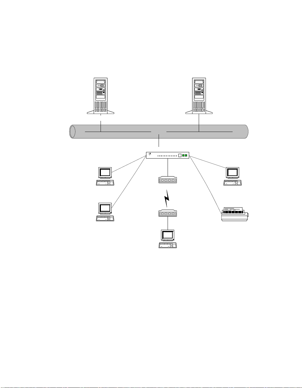
Term inal server configuration - remote devices and RealPort
Application Server
PSTN or
Frame Relay
Modem or DSU/CSU
PortServer II
PortServer
16
Terminal
Terminal
Printer
Terminal
Figure 3 PortServer II - Remote Devices and RealPort
In this configuration, several “dumb” terminals are connected to a corporate application server by means of a PortServer II and the PSTN (Public Service Telephone Network) or Frame Relay. This example shows that it is also possible to co nnect a variety
of different de vices to the PortServer I I in a “dial-u p” conf iguration, i ncluding printers, modems, and other peripherals that might be found in a typical branch or satellite
office. Features to note include:
• The corporate application server may be running RealPort software (see
11, Configuring RealPort Connections
• PortServer II’s Ethernet port is configured with an IP address (s ee
).
Chapter 4
Chapter
).
• PortServer II and the application server could be connected by a “dial-up” line
(not shown, see
Chapter 9, Configuring Modem Connections
).
• Te rm ina ls, mo de m, and pri n ter are co n nect ed to seri al ports on Port Se rv er II.
Page 12 Introduction 90030500B
Page 33

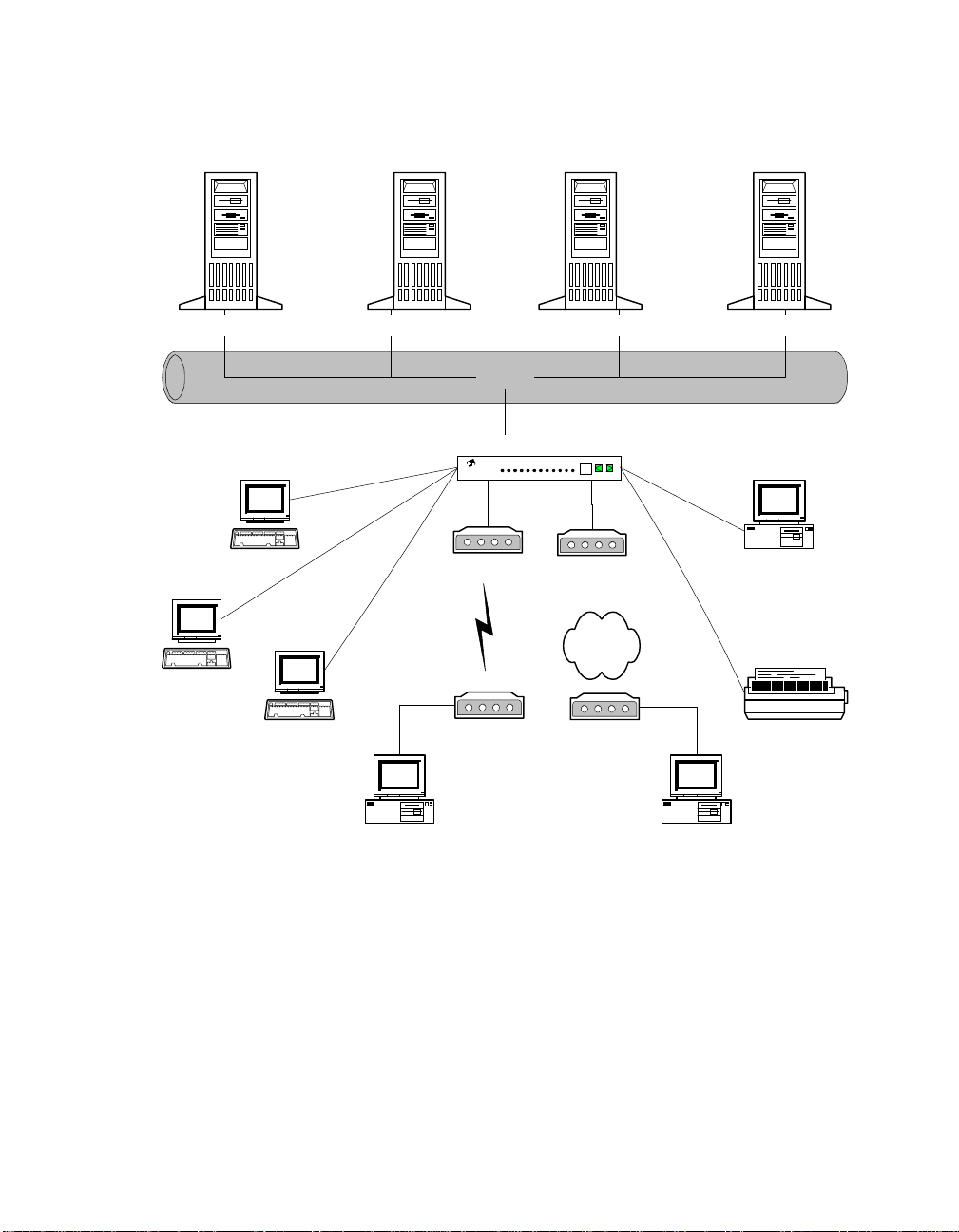
Terminal server configuration - multiple remote devices at several locations
Application Server 1 Application Server 2
Ethernet
PortServer II
PortServer
PortServer II
PortServer
PSTN or
16
Frame Relay
PortServer II
PortServer
Terminal
16
16
Modem
PortServer II
PortServer
TerminalTerminal Terminal Printer
16
Figure 4 PortServer II with multiple remote devices at several locations
In this configuration, several branch or satellite offices are connected to a corporate
application server by means of PortServer IIs and the PSTN (Public Service Telephone Network) or Frame Relay. Each location includes printers, modems, and other
periphera ls. Featu res to note i nc lude:
• The corporate application server is connected to the main corporate LAN.
• The corporate LAN is connected to the PSTN by a PortServer II (see
Chapter 9
• The corporate application server may be running RealPort software (see
).
11
90030500B Introduction Pa ge 13
).
Chapter
Page 34

• Each remote location is connected to the PSTN by a PortServer II (see
Chapter 9
• Each remo te PortServer II can b e configured to call the corporate server, or the
corporate server can call each remote location. Alternatively, the configuration
could allow either location to initiate a connection.
Note:
If the remote offices are equipped with “smart” terminals or PCs, a
PortServer II at a remote office can call another remote office.
• The Ethernet ports on the remote PortServer IIs are not used in this configuration.
Note:
The Ethernet port may require an IP address assigned to it to provide correct functionality. The address may be re-used for the WAN connections
(this is sometimes called “unnumbered” IP link operation).
• The remote peripherals are all connected directly to serial ports on the PortServer
IIs.
TIP — Leased Lines
If you are using PortServer II with standard leased lines and synchronous CSUs,
Frame Relay often gives the best results. If you have a synchronous CSUs, PPP may b e
the best option. Note that the DCD signal is igno red for asynchronous connections.
).
Page 14 Introduction 90030500B
Page 35

Communications server co nfiguration - remote dial-in users at
several locations
Application Server
Ethernet
PortServer II
Modem Modem
Mobile user with
laptop computer
PortServer
Modem
PSTN
16
Telecommuter, with
PC Compatible
Modem
Bank
Figure 5 PortServer II with remote dial-in users
In this configuration, several sales personnel and telecommuters, are connected to an
application se rver by means of a PortServer II and the PSTN. Features to note include:
• Each dial-in user has access to the corporate server.
• The corporate server is connect ed to PortServer II by Ethernet (see
Chapter 4
).
• RealPort software is not required on the corporate server.
• The remote users connect on dial-in TCP/IP connections, using PPP, SLIP, or
CSLIP. For example, they may use Windows 95’s HyperTerminal program to
make PPP connections (see
Chapter 9
).
• PortServer II can make a primary authentication of users, or the server may be a
RADIUS server for e ase of configuration (see
Chapter 15, Configuring RADIUS
).
90030500B Introduction Pa ge 15
Page 36

Communications server configuration - di al-out access to the
Internet
User 1 (PC)
Ethernet
PortServer II
PortServer
PSTN or
Frame Relay
Internet Service Provider
User 2 (X-terminal)
16
Figure 6 PortServer II - Dia l-Out Access to the Internet
In this configuration, several satellite or remote users are provided with access to an
ISP (Internet Service Provider) by a PortServer II and the PSTN (Public Service Telephone Netwo r k) or Fr am e Relay (s ee
Chapter 14
). This permits the user full access to
all Internet options, including e-mail and World Wide Web (WWW) if they have the
appropriate software installed on their terminals. Features to note include:
• PortServer II is configured to provide a dial-out PPP link to the ISP.
• The link may be available at all times, only at certain times, or only on demand,
depending on traffic an d billing considerations (see
Chapter 8
).
• PortServer II is connected to the local user’s terminals by Ethernet.
• It is not neces sary for local users to log into the Internet service individually. PortServer II will log in for all configured users (see
Chapter 9
Page 16 Introduction 90030500B
).
Page 37

Specifications
Network compatibility
• Ethernet IEEE 802.3 standard
•
One 10BaseT twisted-pair Ethernet port with an RJ-45 8-pin connector
•
One 10Base2 Ethernet port with a BNC coaxial connector
Ports
• 16 EIA RS-232 synchronous/asynchronous serial ports, each with an RJ-45 connector
• 115.2Kbps is available on all 16 ports. Connection of an expansion module m ay
reduce the availabl e bandwidth.
• Support for TCP, IP, ICMP, UDP, telnet, reverse tel net, rlogin, and ARP.
• One E BI ( Exter nal B us I nte rface) connector, allowing the connection of external
modules that provide a total of up to 64 ports
Power Requirements
External 43W universal 50/ 60Hz power supply included. Internal supplies:
• +5 volts ± 5% 1250 mA typical
• +12 volts ± 5% 250 mA typical
• –12 volts ± 5% 50 mA
Environment requirements
• Ambient temperature 10° C (50° F) to 55° C (130° F)
• Relative humidity 5% to 90%
• Air movement 30 CFM Forced
• Altitude 0 to 3,660 meters (0 to 12,000 feet)
Dimensions
• Length 12 inches (305 mm)
• Widt h 7 inches (224 mm)
• Height 2.4 inches (57 mm)
• Weight 2.25 lbs (1.0 kg)
Free-standing and rack-mount versions are available.
90030500B Introduction Pa ge 17
Page 38

Limits
PortServer II includes the following limits:
Users
WAN s
Links
IP Routes
Stanzas
Menus
Maximum 64 internal users, regardless of whether expansion
modules are connected. Use of an external RADIUS server
allows additional users, up to the limit of the RADIUS server.
Maximum 128. 64 outgoing connections, waiting for traffic,
and 64 established via RADIUS.
Maximum 64 of each.
Maximum 50 static routes.
Maximum 24 in each script.
User navigation menus can have a maximum of 20 lines,
including two title lines.
Page 18 Introduction 90030500B
Page 39

Chapter 2
Operation
When should I read this Chapter?
Read this chapter if you are unfamiliar with PortServer II, and want to learn about its
controls, indicators, and connectors.
In this Chapter
This chapter describes the controls, indicators, and connectors on PortServer II, and
describes how to interpret the displayed information. It includes the following topics:
Topic Page
PortServer II Front Panel 20
Interpreting the LED Indicators 22
PortServer II Side and Rear Panels 25
90030500B Chapter 2 Page 19
Page 40

PortServer II Front Panel
Pushbuttons
™
Board
PS
ORT ERVER
ETHERNET
II16
LED Indicators Alphanumeric Display
CCITT
SERIAL
103 104
105 106 107 109
TD RD
RTS CTS DSR DCD
TD RD
LI POL CS RX
SERIAL RECEIVE TRANSMITTWISTED
PAIR
108 125
DTR RI
ERR OVF
OFC IFC
TX COL
Figure 7 PortServer II Front Panel
LED indicators
These show the current status of a serial port or the Ethernet connection. Details of
how to interpret the information displayed are given later in this Chapter. The LEDs
can also show diagnostic information, as described in
Chapter 17, Troubleshooting
.
Alphanumeric display
If the alphanumeric display shows a number, the information shown on the LED indicators relates to the serial port of that number. For example, if it shows 16, the information on the LED indicators is for Port 16.
If the alphanumeric display shows EA, the information shown on the LED indicators
relates to E
thernet Activit y.
If the alphanumeric display shows PU, the LED indicators show P
rocessor Utilization
in a bar gr aph-like presentation. The more LEDs that are lit, the greater the CPU activity.
If the alphanumeric display shows AC, PortServer II has powering up and is now in
normal operating mode.
Other indications on the display identify possible fault conditions. Refer to
17, Troubleshooting
Page 20 Operation 90030500B
for information on fault codes.
Chapter
Page 41

Pushbuttons
There are two pushbuttons, one marked with a left arrow and one with a right arro w.
You can use these to:
• Select a serial port to monitor. If you press the left arrow, the number on the
alphanumeric display decrements and information for that serial port is shown on
the LED indicators. Similarly, if you press the right arrow, the number on the
alphanumeric display increments and information for that serial port is shown on
the LED indicators.
• Select diagnostic test s, a s described in
• Reset PortServer II to factory default settings, as described in
Troubleshooting
.
Chapter 17, Troubleshooting
.
Chapter 17
,
90030500B Operation Page 21
Page 42

Interpreting the LED Indicators
The LED indicator s are used to display two different types of status information. If the
alphanumeric display shows a port number, the LED indicators display serial port status information and the labels
shows EA, the LED indicators display Ether net activ ity and the labe ls
apply. If the alphanumeric display shows AC or PU, the LED indicators do not display data.
Serial port status
You can display the status of a serial port by pressing either of the pushbuttons until
the port number appears on the alphanumeric display. The LED indicators then provide RS-232 line status information (in a similar way to a breakout box) and flow control information, as follows:
Signal CCITT Description
TD 103 Transmitte d Data
RD 104 Received Data
the LEDs apply. If the alphanumeric display
above
below
the LEDs
RTS 105 Request to Send
CTS 106 Clear to Send
DSR 107 Data Set Ready
DCD 109 Data Carrier Detect
DTR 108 Data Terminal Ready
RI 125 Ring Indicator
OFC - Output is Flow Controlled
IFC - Input is Flow Controlled
Page 22 Operation 90030500B
Page 43

Ethernet activity
You can display the status of the Ethernet connection by pressing either of the pushbuttons until EA appears on the alphanum eric display. The LED indicators then provide Ethernet status inf ormation, as follows:
Signal Function Description
TD S erial data Serial data has been transmit-
ted on any of the serial ports
RD Serial data Seri al data has been received
on any of the serial ports
LG Twisted pair Line Good. Indicates a good
connection to the Ethernet
hub box.
POL Twisted pair Polarity is backwards. Indi-
cates that the twisted pair wiring has been installed with the
wires transposed. PortServer
II will still operate correctly.
CS Receive Carrier Sense. Blinks when
PortServer II senses the
Ethernet carrier signal.
RX Receive Blinks when PortServer II
detects a packet destined for
itself.
90030500B Operation Page 23
Page 44

Signal Function Description
ERR Receive Network error on packet
received, for example, CRC,
Frame, or FIFO overrun.
OVF Receive Overflow. Lights when
packets arrive faster than
PortServer II can process
them.
TX Transmit Lights when PortServer II is
transmitting a packet.
COL Transmit Lights when PortServer II
detects a collision on the network. This may be a collision
between any packets, not necessarily packets destined for
or originated by PortServer II
devices.
Page 24 Operation 90030500B
Page 45

PortServer II Side and Rear Pan els
The connectors for the Ethernet cable, the power on/off switch, and the D.C. power
supply are loc ated on the left-hand side panel of PortServer II (viewed from the f ront),
while the serial port connectors are on the rear panel. The locations of connectors are
shown below:
Side pa nel
Expansion Module
Connector
Power Socket
Figure 8 PortServer II Side Panel
10BaseT Connector
10Base2 Connector
Power on/off switch and socket
The D.C. power connector from the power unit provided with PortServer II should be
inserted in this socket. Use the switch to turn the PortServer II on or off.
Caution!
This switch does not disconnect power from the PortServer II
power unit and there may be 110V/220V power present on the
power unit when this switch is set to 0 (off). Take care if you are
doing installat ion or service work.
EBI Out connector
This is provided for the connection of a compatible expansion module from the Digi
International PORTS range. Refer to the expansion module documentation for more
details.
90030500B Operation Page 25
Page 46

Thinnet connector, twisted pair connector
These permit a single connection to a compatible Ethernet hub. The internal circuitry
senses whether you have made a 10BaseT connection or a 10Base2 (coaxial) connection, and functions accordingly.
Rear panel
The rear panel provides 16 identical RS-232 compatible serial connectors. Port 1 is at
the left, viewed from the rear.
Port1
Port8
Figure 9 PortServer II Rear Panel
Port9
Port16
Page 26 Operation 90030500B
Page 47

Chapter 3
Installation
When should I read this Chapter?
Read this chapter before you insta ll and connect a PortServer II.
In this Chapter
This chapter describes how to install PortServer II, including site planning procedures
and information on basic safety. It also includes descriptions of the cables that you
will require. This chapter is divided into the following sections:
Topic Page
Before you Begin 28
Surveying the Installation Site 28
Inspecting PortServer II 31
Site Preparation 32
Installing and Connecting PortServer II 34
Wiring Ports f or Specific Devices 48
Connecting to the Ext ern a l Bus Inte rfac e 52
90030500B Chapter 3 Page 27
Page 48

Before you Begin
Before you can install PortServer II, you must do the following:
• Select a location.
• Determine cabling requirements and obtain proper cables.
• Have available a terminal (or PC with terminal emulation software) to configure
PortServer II.
Surveying the Installation Site
1. Identify the best location to place PortServer II. You may want to review the
Environment
below.
2. Locate the relevant connection points to the Ethernet and each PC, terminal,
modem, and printer to which you will connect PortServer II. Measure the distance
from the PortServer II location to each connection point.
3. Decide the length and type of cable required to make each connection. Remember
that each cable should be longer than the distance you measured to allow for tidy
routing.
4. Check that the cable lengths are within the maximum distance limitations for that
type of cable, using the information in
below. If any of the maximum distances are exceeded, you may have to relo-
tions
cate PortServer II.
5. If the cable lengths do not exceed the maximum specified distance, obtain the
required cables.
requirements and the information given on
Recommended Maximum Distance Limita-
Interference Limitation
Site
Interference limitation
Reliable operation of PortServer II can be compromised by electromagnetic interference generated in the connecting cables. Typically, this interference may be de rived
from three sources:
• Plant and equipment containing electric motors, such as air conditioners or heating pumps, or their connecting cables
• High power radio transmitters
• Lightning strikes
Page 28 Installation 90030500B
Page 49

You can m inimize the risk o f i nte rfer en ce b y u s ing co ax ial o r tw ist ed-p ai r c ab les with
grounding connectors at each end and junction point. You should not exceed the maximum distances specifi ed under
Recommended maximum distance limitations
on Pa ge
30.
If any of your cables pass between buildings or on the outside of buildings, you should
give special consideration to the possibility of lightning strikes. The electromagnetic
pulse carried by lightning and similar high-energy phenomena can induce enough
energy in cables to destroy PortServer II’s circuitry. If your installation site is subject
to lightning strike s, you may want to consid er lightning suppression and shielding.
90030500B Install ation Page 29
Page 50

Recommended maximum distance limitations
The maximum recommended length of each type of cable connection you may use
with PortServer II are shown below.
Note:
Although PortServer II may operate adequately if you exceed a given limitation, performance may be degraded.
Ethernet
10BaseT
megabits/second (1 0 Mbps).
10Base2
megabits/second (1 0 Mbps).
: Maximum distance of 330 ft (100 M) at a transmission rate of 10
: Maximum distance of 610 ft (185 M) at a transmission rate of 10
EIA RS-232 serial ports
Maximum distance depends on the data rate and the type of cabl e:
Table 1 RS232 Serial Port Specifications
Data Rate (Baud) Distance (ft) Distance (M)
2400 200 60
4800 100 30
9600 50 15
19200 25 7.5
38400 12.5 3.8
57600 6.3 1.9
115200 3.2 0.9
V.24 cabl e
If you are connecting to a Frame Relay service, you require a fully V.24-compatible
cable. Distance limitations are the same as for serial cables.
Page 30 Installation 90030500B
Page 51

Inspecting PortServer II
Do not unpack PortServer II until you are ready to install it. When you unpack the
shipping box, check that you have the following items:
• One PortServer II unit
• Power supply unit with integra l cords
• One RJ-45 to DB-25 cable leg converter. This is intended for connecting the terminal or PC on which you will configure PortServer II. You will require a nullmodem cable or adapter to provide full terminal functions using this cable.
Note:
If you require additional cables, contact your Digi International dealer or
distributor.
• This
• A warranty card and associate d paper work.
Examine PortServer II and power supply unit for signs of physical damage or
breakage.
If anything is miss ing or appears damaged, or if you encounter problems when installing or configuring PortServer II, contact your dealer or distributor immediately.
User’s Guide
and associated
Command Reference Guide
.
Tools and equipment requi red
No special tools or equipment are required to install PortServer II.
90030500B Install ation Page 31
Page 52

Site Preparation
Site environment
The location you select for your PortServer II is extremely important for its proper
operation. If it is placed too close to other equipment or in a hostile environment, you
may cause equipment failures or errors that you could otherwise avoid.
Before you begin installation, identify the best location using the following guidelines:
• PortServer II generates heat and consequently requires adequate circulation to
maintain its spe cified operating temperature s. Try to allow at least 12 ft (0.3 M) of
ventilation space above and on all sides. Never cover or obstruct the ventilation
slots provided on the unit.
• Always follow the ESD prevention procedures given later in this c hapter when
you work on PortServer II. Damage from static discharge can cause immediate or
intermittent failure.
• Do not position PortServer I I close to electrical equipmen t such as electric motors
or air conditioners. Interference fro m e le ct rical eq uipment may c au s e in te rm itt ent
failures.
• Do not install PortServer II in an area where condensation, water, or other liquids
may be present. This may cause a safety hazard and cause failure of the equipment.
• Ensure that the cover is secure and that all cables are firmly in place on completion of installation. This will reduce safety hazards and eliminate the chance of
failures due to cable disconne ction.
Page 32 Installation 90030500B
Page 53

Safe installation practices
Read the installation instructions below and the associated warnings completely
before beginning.
Warning!
!
The power supply provided with PortServer II is a sealed unit
and contains no user-serviceable parts or adjustments. Do not
attempt to op en or ot her w i se tamper with the po w er supply.
• Locate the power o ff switch or mai n circu i t breaker for the room in which you are
working. If an electrical accident occurs, turn OFF the power immediately.
• Operate PortServer II only from the external power source complying with the
requirements indicated in the
the type of power source, contact your deal er or power company.
• PortServer II’s power supply is provided with a 3-wire plug, which includes a
ground connection as a safety f eature. I f you are unable to insert the plug into your
outlet, have an electrician replace the obsolete outlet. DO NOT attempt to defeat
the safety feature of the plug.
• If you need to use a power extension cord, make sure the total ampere rating of all
equipment plugged into the extension cord does not exceed the extension cord
ampere rating. Also, make sure the total ampere rating of all equipment plugged
into the wall outlets does not exceed the capacity of the outlet.
Specifications
in
Chapter 1
. If you are not sure of
• If PortServer II exhibits unexpected behavior at any time (for example, smokes or
becomes excessively hot), disconnect it from the power source immediately and
obtain service assistance.
• If PortServer II is exposed to moisture or condensation, disconnect it from the
power source immediately and obtain service assistance.
• Look carefully for potential hazards in your work area, such as damp floors,
ungrounded power extension cables, and missing ground connections.
90030500B Install ation Page 33
Page 54

Installing and Connecting PortServer II
General procedure
When you are ready to complete installation, follow this procedure:
1. Place PortServer II in the required location.
2. Locate and identify each connecting cable.
3. Connect each signal cable to PortServer II and to the required destination (for
example, terminal, PC, modem, printer, or Ethernet). Detailed procedures are
given in
4. Connect the power uni t to PortServer II and to the power source. Do not switch on
until instruct ed.
Connecting PortServer II to serial devices
Connecting PortServer II to the Ethernet LAN
Connect your Ethernet network cable to the appropriate connector on the left-hand
side of PortServer II. Refer to your network documentation for appropriate procedures
and precautions.
following.
If you are using a Thinnet (10Base2) cable, plug the cable into the BNC coaxial
connector ma rk ed
If you are using Twisted Pair (10BaseT) cable, plug the RJ-45 connector into the
10BaseT connector marked
Page 34 Installation 90030500B
THINNET
.
TWISTED PAIR
.
Page 55

Connecting PortServer II to serial devices
General
Each of PortServer II’s serial ports is provided with an RJ-45 10-pin jack socket. You
can connect a ser ial device to the port using a cable term inated with any of the following plugs:
• Eight pin RJ-45 plug
• Ten pin RJ-45 plug
• Four pin RJ-11 plug
• Six pin RJ-11 plug
The RJ-45 plugs are the same physical size, but the ten pin version has one additional
wire at each end of the row of contacts. Thus pins 1 through 8 of the eight pin version
correspond to pins 2 through 9 of the ten pin version.
Similarly, the RJ-11 plugs are the same size, but the six pin version has two extra pins
at either end.
RJ-11 plugs are smaller than RJ-45 plugs, but are designed to fit into the center of an
RJ-45 socket. The pins are a ssigned from the center and are always in the same location, regardless of the size of plug. For example, the pins of a six pin RJ-11 plug carry
the same signals as the center six pins of an eight or ten pin RJ-45 connector.
Caution!
If you insert an RJ-11 plug into an RJ-45 connector, take care to align
the pins correctly.
The wiring of the various plug types is shown on the following pages:
90030500B Install ation Page 35
Page 56

Ten pin RJ-45
The ten pin RJ-45 plug carr ies all eight of the RS-232 signals supporte d by PortServer
II, together with two ground lines, SG (Signal Ground) and GND (Chassis Ground). It
includes two modem control lines, RI (Ring Indicator) and DCD (Data Carrier
Detected).
Figure 9 RJ-45 10 Pin Plug and Jack Wiring
Page 36 Installation 90030500B
Page 57

Eight pin RJ-45
The eight pin RJ-45 plug carri es the RS-232 signals sup ported by PortServe r II, except
for the two modem control lines, RI (Ring Indicator) and DCD (Data Carrier
Detected). It also provides the two ground lines, SG (Signal Ground) and GND (Chassis Ground).
Pin 1
Pin 8
Pin 1
Pin 10
RJ-45 - 8 Pin Plug RJ-45 - 10 Pin Jack
Signal
RTS
GND
TxD
RxD
SG
CTS
DTR
Pin Pin
1DSR
2
3
4
5
6
7
8
N/C
N/C
Figure 10 RJ-45 8 Pin Plug and Jack Wiring
10
1
2
3
4
5
6
7
8
9
Signal
RI
DSR
RTS
GND
TxD
RxD
SG
CTS
DTR
DCD
Note:
90030500B Install ation Page 37
PortServer II software provides DCD in eight pin configurations. See
9, Configuring Modem Connections
.
Chapter
Page 58
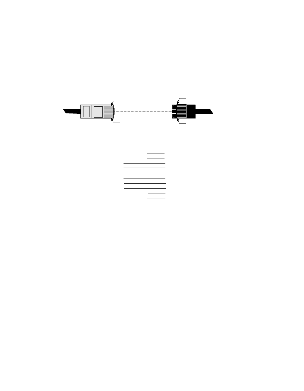
Six pin RJ-11
The six pin RJ-11 plug is suitable for connections that require limited control
signals, for example modems or printers that employ hardware handshaking.
Pin1
Pin6
Pin1
Pin10
RJ-45 - 6 PinPlug RJ-45 - 10 PinJack
Signal
Pin Pin
N/C
RTS
GND
TxD
RxD
SG
CTS
1
2
3
4
5
6
Figure 11 RJ-11 6 Pin Plug and Jack Wiring
N/C
N/C
N/C
10
Signal
1
RI
2
DSR
3
RTS
4
GND
5
TxD
6
RxD
7
SG
8
CTS
DTR
9
DCD
Page 38 Installation 90030500B
Page 59
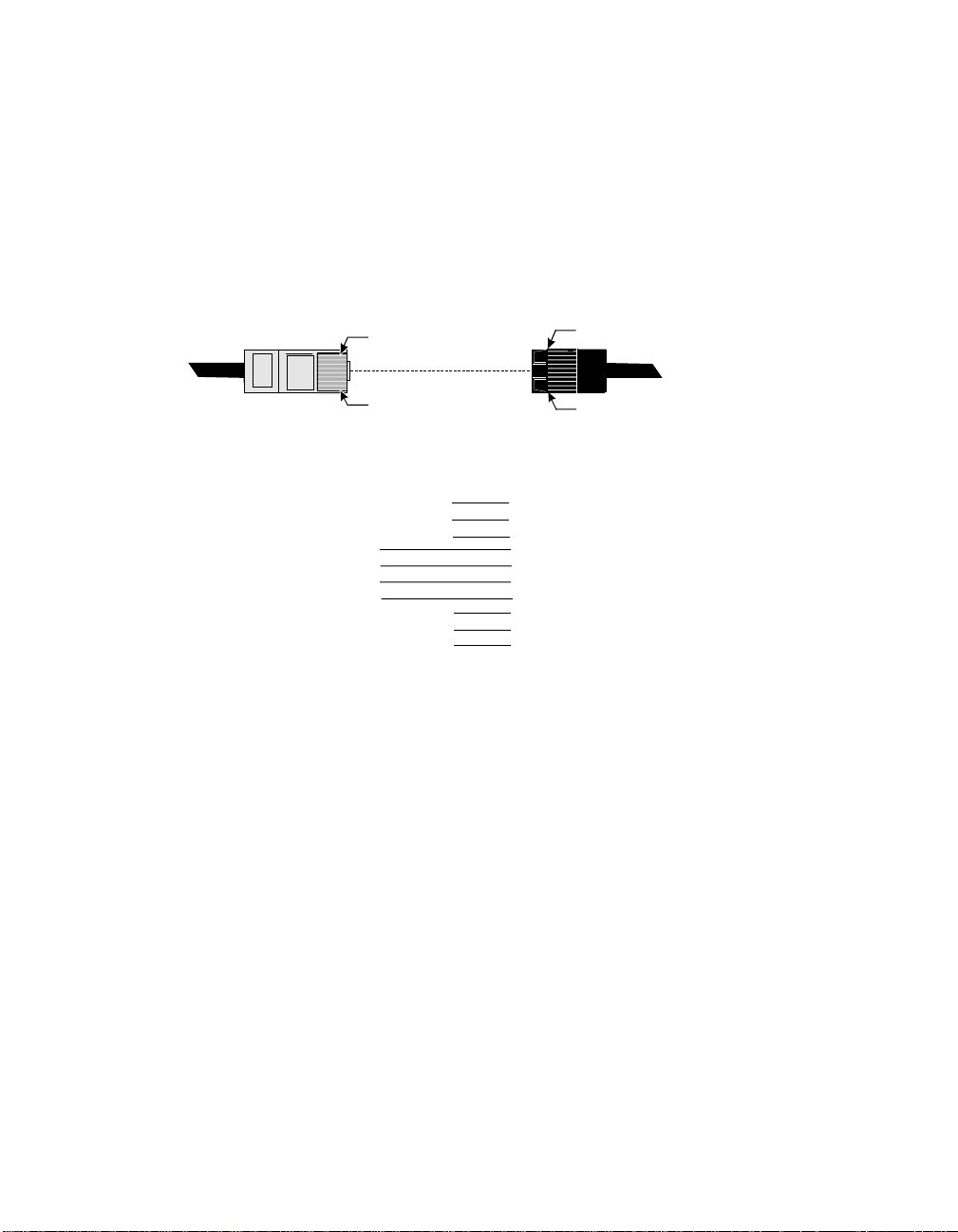
Four pin RJ-11
The four pin RJ-11 plug is suitable for connections that require only data signals, for
example modems or printers that employ software handsha king. No hardware handshaking is available with this configuration.
Pin 1
Pin 4
Pin 1
Pin 10
RJ-45 - 4 Pin Plug RJ-45 - 10 Pin Jack
Signal
Pin Pin
N/C
N/C
GND
TxD
RxD
SG
1
2
3
4
Figure 12 RJ-11 4 Pin Plug and Jack Wiring
N/C
N/C
N/C
N/C
N/C
10
Signal
1
RI
2
DSR
3
RTS
4
GND
5
TxD
6
RxD
7
SG
8
CTS
DTR
9
DCD
90030500B Install ation Page 39
Page 60

Connecting the configuration terminal
Connect a PC or terminal to Port 1 on the rear of PortServer II to use during the configuration procedure described in
Chapter 4, Basic Configuration
quently use this terminal for system management or other purposes. If you use a PC,
you will require a terminal emulator program.
1. Obtain a suitable cable to connect your terminal to the seria l port on PortServer II.
The RJ-45 to DB-25 cable leg connector supplied with PortServer II was intended
for this purpose. If you prefer, you can also construct or obtain your own cable.
If you construct or obtain your own cable, you only need to connect the TxD
(Transmitted Data), Received Data (RxD), and Signal Ground (SG) cables, as
shown below.
. You can subse-
RJ-11 (4 Pin)
Note:
GND 1 1 GND
TxD 2 2 TxD
RxD 3 3 RxD
SG 4 7 SG
=Cable
Shield
Figure 13 Simple 3 Wire cable
Any cable you c onstruct or obtain must be shielded to comply with F CC cer ti-
DB-25 Male
fication requirements. The shield must be connected to Chassis Ground
(GND) at one end of the cable.
In addition to the configuration illustrated above, you can also use a 6-pin RJ-11
plug, or an 8 pin or 10 pin RJ-45 plug. (See Page 35).
2. Fit the DB-25 connector to the terminal. If your terminal does not have a DB-25
connector, you will also have to obtain an adapter.
3. Fit the RJ-11 or RJ-45 plug to PortServer II. If you use an RJ-11 plug, ensure that
you center it on the jack.
Page 40 Installation 90030500B
Page 61

Connecting to terminals and PCs
You can connect a terminal to any available serial port on PortServer II.
1. Obtain a suitable cable to connect the terminal to the serial port on PortServer II.
The wires that must be available depend on whether the terminal requires hardware handshaking.
If the terminal does not require hardware handshaking, you can use a simple 3wire cable as shown below:
RJ-11 (4 Pin)
Note:
GND 1 1 GND
TxD 2 2 TxD
RxD 3 3 RxD
SG 4 7 SG
=Cable
Shield
Figure 14 Simple 3 Wire cable
Any cable you c onstruct or obtain must be shielded to comply with F CC cer ti-
DB-25 Male
fication requirements. The shield must be connected to Chassis Ground
(GND) at one end of the cable.
In addition to the configuration illustrated above, you can also use a 6-pin RJ-11
plug, or an 8 pin or 10 pin RJ-45 plug. (See Page 35).
If the termin al requires hardware handshaking, use the cable shown on the following page. This configuration assumes the terminal uses Data Terminal Ready
(DTR) for handshaking; check your terminal or PC documentation for further
information.
90030500B Install ation Page 41
Page 62

RJ-45 (8 pin) DB-25 Male
DSR 1 4 RTS
RTS 2 5 CTS
GND 3 1 GND
TxD 4 2 TxD
RxD 5 3 RxD
SG 6 7 SG
CTS 7 20 DTR
DTR 8
=Cable
Shield
Figure 15 Terminal cable with DTR handshaking
2. Fit the DB-25 connector to the terminal. If your terminal does not have a DB-25
connector, you will also have to obtain an adapter.
3. Fit the RJ-11 or RJ-45 plug to PortServer II. If you use an RJ-11 plug, ensure that
you center it on the jack.
Page 42 Installation 90030500B
Page 63
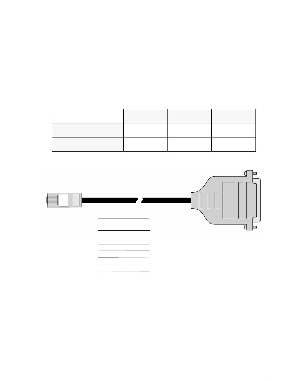
Connec ting to modem s
You can connect a modem to any available serial port on PortSer ver II.
1. Obtain a suitable cable to connect the modem to the serial port on PortServer II.
Most modems require a 10-pin cable; we suggest you obtain one of Digi International’s RJ-45 to DB-25 straight-through cables:
Table 2 A vailable Cables
DB-25 Male DB-25 Female DB-9 Male
24 Inch Cables
48 Inch Cables
61020024 61030024 61070024
61020048 61030048 N/A
This cable type is illustrated below:
RJ-45 (10 pin) DB-25 Male
Gnd - Shell Chassis Gnd
TxD 5 2 TxD
RxD 6 3 RxD
RTS 3 4 RTS
CTS 8 5 CTS
DSR 2 6 DSR
Signal Gnd 7 7 Signal Gnd
DCD 10 8 DCD
DTR 9 20 DTR
RI 1 22 RI
Figure 16 Full 10 Wire Modem cable
Note:
Any cable you c onstruct or obtain must be shielded to comply with F CC cer tification requirements. The shield must be connected to Chassis Ground
(GND) at one end of the cable.
90030500B Install ation Page 43
Page 64

2. Fit the DB-25 connector to the modem. If your modem does not have a DB-25
connector, you will also have to obtain an adapter.
3. Fit the RJ-11 or RJ-45 plug to PortServer II. If you use an RJ-11 plug, ensure that
you center it on the jack.
ALTPIN
PortServer II includes a feature called ALTPIN that allows you to use 8 pin RJ-45 to
DB-25 adapters. ALTPIN swaps pins 2 and 10, making DCD available on pin 1 of an
8 pin RJ-45 connector. If you use ALTPIN, you must also configure the PortServer II
port with the com mand
set flow altpin
details).
The cable wiring for ALTPIN is shown below:
RJ-45 (8 pin) DB-25 Male
DCD 1 8 DCD
RTS 2 4 RTS
GND 3 1 GND
TxD 4 2 TxD
RxD 5 3 RxD
SG 6 7 SG
CTS 7 5 CTS
DTR 8 20 DTR
=Cable
Shield
(see the
Command Refere nce Guide
for
Figure 17 ALTPIN cable
Note:
Digi Inter nat ion al’s softw are can u se t h e DSR signal in modem control applications. If your modem has auto-answer capability, you do not require the
Ring Indicator.
Page 44 Installation 90030500B
Page 65

Connecting to printers
You can connect a printer to any available serial port on PortServer II.
1. Obtain a suitable cable to connect the printer to the serial port on PortServer II.
The wires that must be available depend on whether the printer requires software
(XON/XOFF) or hardware (D T R /DS R) handshaking.
If the terminal employs software handshaking, you can use a simple 3-wire cable
as shown below:
RJ-11 (4 Pin)
Note:
GND 1 1 GND
TxD 2 2 TxD
RxD 3 3 RxD
SG 4 7 SG
=Cable
Shield
Figure 18 Printer cable with Software handshaking
Some Okidata printers use a control signal called Supervisory Send Data
DB-25 Male
(SSD) on pin 11, instead of DTR. For these printers, connect CTS on the RJ45 connector to pin 1 1 of the DB-25 conn ector, instead of pin 20.
If the terminal requires hardware handshaking, use the cable shown on the following
page.
90030500B Install ation Page 45
Page 66

RJ-45 (8 pin) DB-25 Male
DSR 1 4 RTS
RTS 2 5 CTS
GND 3 1 GND
TxD 4 2 TxD
RxD 5 3 RxD
SG 6 7 SG
CTS 7 20 DTR
DTR 8
=Cable
Shield
Figure 19 Printer cable with Hardware handshaking
Note:
Any cable you c onstruct or obtain must be shielded to comply with F CC cer tification requirements. The shield must be connected to Chassis Ground
(GND) at one end of the cable.
In addition to the configurations illustrated above, you can also use a 6-pin RJ-11
plug, or an 8 pin or 10 pin RJ-45 plug for either applicat ion. (See Page 35).
Page 46 Installation 90030500B
Page 67

Connecting to Frame Relay
If you plan to use PortServer II with a Frame Rel ay service, you must use a V24 cable
similar to the one shown in Figure 20. One cable of this type is supplied with each
PortServer II. An RJ-45 10-pin male connector is provided at the PortServer II end of
the cable, and a DB-25 25-pin male connector is provided for the Frame Relay termination.
RJ-45 (10 pin) DB-25 Male
Chassis Gnd 4 Shell Chassis Gnd
-TxD 5 2 -TxD
-RxD 6 3 -RxD
RTS 3 4 RTS
CTS 8 5 CTS
DSR 2 6 DSR
Signal Gnd 7 7 Signal Gnd
DCD 10 15 DCD
DTR 9 20 DTR
RI 1 17 RI
(Pins not lis ted
have no conn ection)
Figure 20 V24 Cable for Frame Relay
90030500B Install ation Page 47
Page 68

Wi ring Ports for Specific Devices
The table below summarizes the characteristics of and wiring requirements for the
device types av ail ab le on Po rt Se rv er II.
Device
Type
term
prn
host
hdial
hio
min
mout
mio
Detailed explanat ions of these functions are give n bel ow.
Note:
dev=host
DTR + RTS
when idle
high data no ignore
low never yes ignore
low never if DCD hang up
low DCD + data no hang up
low DCD + data if DCD hang up
high DCD raise s no hang up
low never yes hang up
high DCD raise s yes hang up
Device types (
in the
Function Reference Guide
of this
User’s Guide
(Computer or other devices)
Spawn Login
dev=xxx
.
) are set with the
Remote Connect
allowed
set port s
. Procedures are a lso given in later chapters
Action when
DCD drops
command, as described
Use this device type for connecting another computer to a serial port. A typical use
might be connecting a bulletin board system (BBS) to the Ethernet through the
PortServer II. DC D and DTR m ust be cross -conn ected bet we en the Po rtSe rver II an d
the BBS server.
When the server raises DTR to signal that it can receive calls, the PortS erver II sees
DCD go high. It then allows incoming connections from the Ethernet through the
serial connect ion to the server. When an incoming connection is requested, PortServer
II raises DTR, and the server sees DCD go high, indicating there is a call. (This
sequence mimics a modem answering a dial-up call.)
Page 48 Installation 90030500B
Page 69

The server can terminate the connection by dropping DTR, which PortServer II sees
as DCD going low. PortServer II then terminates the incoming connection. If the
incoming connection terminates itself, PortServer II lowers DTR. The server sees
DCD drop, and knows the connection is terminated. DTR remains low for two seconds and input is flushed to assure a clean disconnection.
Termination control using DTR and DCD is the difference between
dev=mout
host
not.
Wiring required:
(described later in this section). Both are used for outgoing connections.
requires that DCD is high before the connection is complete, while
Full 10-wire Null Modem cable.
dev=host
mout
and
does
dev=hdial
Use this device type for connecting another computer to a serial port. DCD and DTR
must be cross-connected between PortServer II and the host. When the host raises
DTR, DCD goes high at PortServer II. When PortServer II receives data, a login is
spawned.
Unlike
PortServer II raises DTR, it brings DCD up at the host immediately.
When the user logs out or the host drops DTR, PortServer II lowers its DTR and
flushes data for two seconds.
dev=min
, there is no two-second delay before the login is spawned. When
dev=hio
Use this dev ice type for connecting ano ther computer to a serial port when you require
bidirectional incoming and outgoing connections. The device behaves like
or
dev=host
.
dev=hdia l
When the host ra ises DTR (raising DCD on the Port Server II), an outgoing connection
can be established. Alternately, if data is received, a login is spawned.
dev=term
Use this device type for “dumb” terminals. When the device is set for a terminal, the
incoming port ignores DCD. All outgoing connect attempts are refused.
Wiring required
90030500B Install ation Page 49
(Termi nals)
: Only TD, RD, and GND connections are needed.
Page 70

dev=prn
PortServer II tr eats printers as outgoing device s that ignore DCD. Any incoming characters are also ignored, until an outgoing connection is established. When a connection is established DTR is raised, otherwise DTR is low. Unlike modem device types,
there is no two second hangup.
This device type can also be used for general purpose outgoing connections
Wiring required:
dev=min
Use this device type for a modem that is used for incoming communications only.
DTR and DCD are supported. In this mode, PortServer II ignores all input until DCD
appears. Then it “flushes” all input for two seconds to discard messages like RING
and CONNECT, before it spawns a login or attempts a connection.
Whenever DCD drops, PortServer II drops DTR. All connections terminate, and any
user is logged out.
When a user logs out or (on an autoconne ct port) the remote system drops the connection, DTR is dropped to hang up the modem. DTR remains low for two seconds to
assure a clean modem disconnection, and then input is flushed to discard messages
such as DISCONNECT.
(Printe rs)
Generally, only TD, RD, and GND connections are needed.
(Modem In)
Wiring requi red
should always be wired in the cable. With multispeed, data compressing modems, you
may also need to wire R TS and CTS for hardware flow control.
dev=mout
Use this device type for a modem requiring outgoing communications only, with full
DTR/DCD modem support.
Until an outgoing connection is made, DTR remains low, keeping the modem from
answering. When an outgoing connection succeeds, DTR is raised.
The state of DCD is ignored until there is a high-low transition of DCD. This closes
the connection, and drops DTR. D TR then remains low for two seconds to assure a
clean modem disconnection, and then input is flushed to discard messages such as
DISCONNECT.
Page 50 Installation 90030500B
: Modem connections require that TD, RD, DCD, DTR and GND
(Modem Out)
Page 71

Wiring required
always wired in the cable. With multispeed, data compressing modems, you may also
need to wire RTS and CTS for hardware flow control.
dev=mio
Use this device type for a bi-directional modem, requiring full DTR/DCD support.
When the modem is idle, PortServer II leaves DTR high so the modem will answer
incoming calls.
If DCD goes high when the device is idle , PortServer II assumes an incoming connec-
tion has been requested and acts like a
again.
If an outgoing connection succeeds when the device is idle, PortServer II switches into
outgoing mode and acts as a
remains low for two s econds to assure a clean modem disconnection , a nd then input is
flushed to discard messages such as DISCONNECT messages.
Wiring required
and GND are wired in the cable. With multispeed, data compressing modems, you
may also need to wire R TS and CTS for hardware flow control.
: Modem connections require that TD, RD, DCD, DTR and GND are
(Modem In & Out)
dev=min
dev=mout
: Bidirectional modem connections require that TD, RD, DCD, DTR
device until the connection is dropped. DTR
device until the device goes idle
90030500B Install ation Page 51
Page 72

Connecting to the External Bus Interface
PortServer II includes an External Bus Interface that permits connections to up to
three external modul es providing additional serial ports. Compatible external modules
from the Digi International range of PORTS modules include:
• PORTS/16em. Provides sixteen additional serial ports.
• PORTS/8em. Provides eight additional serial ports.
• POR TS/8emp. Provides eight additional serial ports and one para llel port.
The connecting cable required is provided with the PORTS module and you should
refer to the PORTS documentation for installation instructions.
An example configuration is shown below, with two PORTS/16em modules
connected to a PortServer II. This arrangement provides 48 serial ports, 16 on
PortServer II, and 16 on each PORTS module.
Figure 21 PortServer II and Expansion Modules
Page 52 Installation 90030500B
Page 73

!
Note:
Warning!
Do not connect a PORTS module to PortServer II while power is
switched o n. This may cause se vere electrical proble ms or damage to PortServer II and the PORTS module.
You may experience performance degradation when using expansion modules
under heavy data throughput. For example, if you have a total of 64 ports, you
can drive some (but not all) ports at 115.2Kbps. The available WAN bandwidth on PortServer II is approximately 3.7Mbps; the maximum port speed
for any given port is either 115.2Kbps, or whatever portion of 3.7Mbps is not
currently in use by other port s that are simultaneously active.
90030500B Install ation Page 53
Page 74

Page 54 Installation 90030500B
Page 75

Chapter 4
Basic Configuration
When should I read this Chapter?
Read this Chapter if you are going to configure a new PortServer II for the first time.
If you want to change or add to the configuration of a previously configured
PortServer II, refer to subsequent chapters.
In this Chapter
This chapter describes a “quick start” method of setting the basic functions of
PortServer II, including its connection to the Ethernet. It also provides a general
description of how to use the configuration commands how to assign users.
The Chapter includes the following topics:
Topic Page
Entering Configurati on Commands 56
On-Line Help 60
Logging on to PortServer II 61
Configuring the Ethernet Connec tion 62
Testing the network connection 65
PortServer II TCP/IP Port Numbers 66
Configuring a User 67
Using the IP Pool 74
90030500B Chapter 4 Page 55
Page 76

Entering Confi gur a tio n Comm a nds
To configure PortServer II, you enter commands at PortServer II’s command line
prompt on the configuration terminal. Type the command syntax including any
options on the configuration terminal keyboard. The descriptions of the commands in
this User’s Guide include only the most common options, and for details of all command options you should refer to the
Note:
Characters that you must type are shown in the format:
command syntax [options]
Abbreviations
Command Reference Guide
.
All PortServer II commands may be abbreviated to their shortest
or letters. For example, you can abbreviate the command:
set user name=jill
to:
set u n=jill
If you enter insufficient letters for PortServer II to identify the c ommand, it will return
an error message.
You may enter an aste risk ( “*”) in place of “
or tables entries of the same type.
range= 1-
” to specify all of the ports
n
unique
initial letter
Page 56 Basic Configuration 90030500B
Page 77

Editing keyst rokes
You can use any of the following keystrokes when entering commands at the
PortServer II command line:
Ctrl + b
Ctrl + f
<
--
Delete
Ctrl + h
Ctrl+p
Ctrl+n
Enter
Ctrl [ Enter
Ctrl+c
Move the cursor left (move back)
Move the cursor right (move forward )
Erase (delete character to the left of the cursor)
Delete the cha racter under curso r
Delete the character to the left of the cursor. (You can change “h”
to another character with the
Command Reference Guide
the
When typed as the first character on a line, this sequence copies
the previous line from the command buffer onto the current line.
When typed as the first character on a line, this sequence copies
the next line from the command buffer onto the current line .
Executes the currently typed command.
Escape character. Used to break out of the current session, either
to another session or to the PortServer II command line.
change “[” to another character with the
described in the
Interrupt character. (You can change “c” to another character with
set keys
the
Guide
.)
Command Reference Guide
command, as described in the
set keys
.)
command, as described in
(You can
set keys
.)
command, as
Command Reference
90030500B Basic Configuration Page 57
Page 78

Specifying the r ange of s e t co nfiguration commands
As a part of a
mand applies. The
set line, set logins
range of ports, while other set commands are applied to a table index.
Note:
Specify a table entry, or a range of table entries, with the range option, in one of three
formats:
set (command) range=value
set
command, you specify which port or table ent ry to which the com-
set flow, set framerelay, set FrDcli, set keys
set ports
, and
If you do not s pecify a range, the
which you are logged in.
commands are applied to a port or
set
command will af fect only the port from
,
This tells the
value
. Type in the rest o f the command after
set (command) range=startvalue-endvalue
This tells the
startvalue
value
.
set
set
through
comman d that the rest of the com mand affects the port nu mber
value
.
command that the rest of the command affects the port numbers
endvalue
. Type in the rest of the command after the value for
end-
It is possible to combine the preceding two methods, separated by commas:
set (command) range=value,startvalue-endvalue,value
You can include multiple command options in the same line with a single range
option. For example:
set line range=1-4 baud=2400 parity=e csize=7 stopb=1
This example sets the serial characteristics of ports 1 through 4 for 2400 baud, even
parity, character size of 7 and 1 stop bit. This could also have been enter ed as:
set line range=1-4 baud=2400
set line range=1-4 parity=e
set line range=1-4 csize=7
set line range=1-4 stopb=1
Page 58 Basic Configuration 90030500B
Page 79

Saving configuration changes to flas h ROM
set
Each
II's Flash Read Only Memory (ROM). If you logged in as root,
If you are not logged in as root,
Important:
Non-root users can only set parameters for their own port. If non-root users wish to
save their parameters in Flash ROM, the configuration command must include
save=on
write=on
Since configuration changes are automatically saved for root users, you must remember to add
command includes an option to save configuration changes into PortServer
save
is on by default.
save
is off by default.
Changes made by a non-root user are valid only for the duration of their
session.
. The System Administrator must also configure this port with
.
save=off
to any temporary changes you make when logged in as
set logins
root
.
90030500B Basic Configuration Page 59
Page 80

On-Line Help
On-line help screens are available for the PortServer II's commands. Help is displayed
if you ente r a “?” by itself or after part of a command line. The help screen will tell
you which parameters are available to complete the command line.
Help menu
Enter a “?” after the Por tServer II prompt with no other parameters to get the top level
help screen, as shown below:
login: root
passwd:
#> ?
admin boot close cpconf
exit info kill mode
newpass ping quit rlogin
send set snmp status
telnet traceroute wan who
?
#>
Command-sp eci fic help
For help on a specific command, type the command name followed by a question
:
mark. The example below asks for help for the command
#> info ?
Displays or clears statistics tables.
syntax: info (table_name)|(table_cmd)
tables:
frame ip icmp tcp
udp clear
#> info
Note:
After you enter a request for help, PortServer II prints the command before
info
the “?” for you on the next command line, anticipating that you will enter the
command next. For example, after the request for help with
notice how the next command prompt is followed by the word
Page 60 Basic Configuration 90030500B
info?
info
above ,
.
Page 81

Logging on to PortServer II
To configure PortServer II with this procedure, you will use a terminal or PC that is
connected to one of the serial ports, as described in
Note:
To log on to PortServer II, proceed as follows:
If you want to configure PortServer II remotely with RARP (not using a local
terminal) , refe r to Con fi gur ing Port Se rv er II o ver the E t hern et on pag e 64.
1. Switch on the terminal or PC. If you are using a PC, start the terminal emulation
software.
2.
Set the terminal parameters to VT-100 emulation, 9600 baud, 8 data, 1 stop, and
no parity.
Note:
3. Switch on PortServer II. The power switch is located on the front of the case . PortServer II’s Power On Self Test (POST) sequence will now run automatically. If it
does not detect any errors, the alphanumeric display will show AC, and the LED
indicators will light in sequence.
These are the fact ory d efa ult Port Se rv er II s ettings and can be changed. If
you are reconfiguring a PortServer II whose parameters have been
changed, use the new parameters. If you do not know the new parameters,
refer to
tory-default se ttings for a port.
Chapter 17, Troubleshooting
Chapter 3, Installation
for details of how to restore the fac-
.
4. When AC is showing on the a lphanumeric display, press the
on your terminal or PC keyboard. The
5. T ype
6. Type
Note:
90030500B Basic Configuration Page 61
root
and press
Note:
screen. Wh en you see a #> prompt, you have successfully logged in, for example:
login: root
passwd:
#>
Always log on as
and press
dbps
These are the factory default PortServer II login and password, and can be
changed. If you are reconfiguring a PortServer II whose login and/or password have been changed, use the new entries. If you do not know the new
login and/or password, refer to
restore the factory-default settings.
. Check that the
Enter
root
. The password you type is not displayed on the
Enter
login:
to configure or reconfigure PortServer II.
Chapter 17, Troubleshooting
prompt should display.
passwd:
Return
prompt should display.
or
for how to
Enter
key
Page 82

Configuring the Ethernet Connection
You now should enter basic network configuration information for the PortServer II.
The information you enter is sto red in the network parameters configuration table.
1. Set the IP address for the PortServer II unit, using the following command:
#>set config ip=xxx.xxx.xxx.xxx
Your network administrator can give you an appropriate IP address to use. For
example, to set an IP address of 192.83.159.1, enter
#>set config ip=192.83.159.1
#>
Note:
If your system supports RARP (Reverse Address Resolution Protocol),
you may be able to a cquire the IP address automatically. See
PortServer II over the Ethernet
on Page 64.
2. Set the Node Name for the PortServer II, using the following command:
#>set config myname=<node_name>
:
Configuring
For example, to set the node name to
#>set config myname=termserver
termser ver
, enter:
3. If applicable, enter the name of the domain that includes the PortServer II unit,
using the following command:
#>set config domain=<domain_name>
For exampl e, to set
#>set config domain=dgii.com
#>
dgii.c om
as the domain name, enter:
4. If you have one, enter the IP address of the Domain Name Service machine that
will translate domain names to and from IP addresses, using the following command.
#>set config nameserv=xxx.xxx.xxx.xxx
For example, to set 192.83.159.2 as the Domain Name Server, enter:
#>set config nameserv=192.83.159.2
#>
Page 62 Basic Configuration 90030500B
Page 83

Note:
If you do not have a Domain Name Server, you can use the PortServer II’s
set host
Command Refere nce Guide
command to build a table of names and IP addresses. (See the
for the command syntax.)
5. Set your network sub-net mask, using the following command:
#>set config submask=xxx.xxx.xxx.xxx
For example to set the mask to 255.255.255.240, enter:
#>set config submask=255.255.255.240
#>
Note:
The default submask is 255.255.255.0.
6. If you have a gateway, set its IP address, using the following command:
#>set config gateway=xxx.xxx.xxx.xxx
For example, to set the gateway address to 198.83.159.3, enter:
#>set config gateway=198.83.159.3
#>
7. Check the time and date, by entering:
set time
Check that the correct time and date are displayed. If the correc t values are not
displayed, enter:
set time time=hour.minute.second date=month.day.year
where the time and date values are the current values, for example:
set time time=11.32.00 date=4.1.96
90030500B Basic Configuration Page 63
Page 84

Configuring PortServer II over the Ethernet
If you do not set the IP address during configuration, PortServer II will attempt to use
RARP (Reverse Address Resolution Protocol) to determine its IP address. If this succeeds, you can configure the remaining PortServer II parameters by connecting to it
using telnet from an administration terminal, instead of using a local terminal connected direct ly to Por tServ e r II.
If you want to use this method of configuration, a RARP server should be available on
the network. Consult your operating system and network software documentation for
further information. (On many UNIX systems, this information can be found in the
manual entry for
Note:
If you do not have a RARP server, you can configure most PortServer II
rarpd
parameters using
with a local terminal before you can use
Running RAR P o n th e server
To use RARP to assign IP addresses to PortServer II’s on your network, the RARP
daemon must be running on the network host. The RARP server maintains a database
of mappings between Ethernet (MAC) addresses and protocol (IP) addresses. When a
client suc h as PortServe r II requests an IP address, the RARP daemon accesses the
database and returns the appropriate address.
).
telnet
. However, you must set PortServer II’s IP address
.
telnet
Note:
The example below is for an SCO server; the file names and responses on
your system may differ.
To enab le RA R P o n a server :
1. Ensure that TCP/IP is running on the server.
2. Add each PortServer I I on your network to the
/etc/hosts
file, in the following for-
mat:
# @(#)hosts 1.2 Lachman System V STREAMS TCP source
# SCCS IDENTIFICATION
127.0.0.1 localhost
132.147.144.246 dgii dgii.com
3. Add each PortServer II on your network to the
/etc/eth ers
file, in the following
format:
# @(#)ethers 4.1 Lachman System V STREAMS TCP source
# SCCS IDENTIFICATION
#
Page 64 Basic Configuration 90030500B
Page 85

#sample ethers file
#
8:0:20:0:fc:6f dgii
4. Remove the comments (# symbols) from the following lines in the
/etc/rc2.d/S85tcp
file, to ensure the RARP daemon runs each time the server is
brought up in multi-user state:
SCO Unix Version 4.2 and below:
# if [ -x/etc/rarpd -a -f /etc/ethers ]; then
# /etc/rarpd -a ; echo “rarpd\c”
# fi
SCO Unix Version 5:
# if [ -x/etc/rarpd -a -f /etc/ethers ]; then
# /etc/rarpd -a &
# echo “rarpd\c”
# fi
Note:
If you nee d to uncomment these lines in either of the e xamples above, you
must start RARPD manually or reboot your server.
5. Reboot PortServer II, and check that you can telnet or rlogin to PortServer II.
Test ing the net work connection
You should now check that you have configured PortServer II correctly by establishing communications with another network machine.
Enter the
by pinging the machine with IP address 192.83.159.227, enter:
#>ping 192.83.159.227
Check that you see a response similar to:
192.83.159.227 is alive
#>
If you do not see this message, check that you have se t the IP address for PortServer II
correctly, and have entered the address of the target machine correctly. Check also
that you have connected the network cable to PortServer II correctly. You can also use
PortServer II’s front panel to monitor Ethernet activity – see
you are unable to resolve the problem, refer to
90030500B Basic Configuration Page 65
command to test the connection. For example, to test the connection
ping
Chapter 2, Operation
Chapter 17, Troubleshooting
. If
.
Page 86

PortServer II TCP/IP Port Numbers
PortServer II provides two ranges of TCP/IP service numbers to which you can connect from other systems:
2001 - 2099 Telnet Connect
2101 - 2199 Raw Connect
A connection made to any 20XX port uses the Telnet protocol, providing full Telnet
compatibility. Use the 20XX ports in commands like:
pr myfile
A connection to any 21XX service is a raw connection, passing eight bit “clean” data.
Use the 21XX ports with R TTY (see
The last two digits in each number indicate the port or group the user is connected to.
If the last two digits are in the range 01 through 64, the user is connected to the specified port. Numbers greater than 64 indicate a
set port group=
When several PortServer II ports are configured with the same group number, they
work like a telephone “hunt group.” Any attempted connection goes to the lowest
numerical port number that can currently accep t a connection.
set altip
The
alternate IP addresses for telnetting to a port or hunt group. (This command does not
support raw connections.) For example, you could replace
telnet abcalt
altip
Note:
table, and
Choosing the wrong range of service numbers, (for example, 20xx instead of
21xx) is a common source of user problems.
telnet dbps-nodename 2001
|
) and custom applications.
port group number
Command Reference Guide
gr oup_number
comman d (See
, if tha t
abcalt
abcalt
is defined in a host table.
Chapter 9
(See
Command Reference Guide
has an IP address associated with group 88 in the
, as configured with
).
) can be used to define
telnet abc 2088
with
Page 66 Basic Configuration 90030500B
Page 87

Configuring a User
For each PortServer II you can configure between one and 64 users, and a password
for each user. These users typically have their own logins, and do not have access to
the PortServer II configuration options. Users may log in via dial-up links or at terminals. The configuration options available depend on their method of access, as
described below.
If you do not have users connecting to your PortServer II (for example, if you are
using it as a printer server), you can ignor e the rest of this chapter.
Note:
Cre a ting a new us e r
You must create an account for each user who can connect through PortServer II, and
configure their basic access and network parameters as follows:
If a user can log in by more than one method (for example, through a local terminal or a dial-up link), you must create a user prof ile for each.
1. Cr eat e a user by ente ri ng a command in the form at :
set user name=<user_name>
<
user_name
For exampl e, to cre ate a user called
set user name=Bill
> would typically be the same user name as on your host systems.
, enter:
Bill
PortServer II displays the list of basic access paramet ers that you will configure
for the user. If this is a new user, default settings are shown for the parameters, as
shown below:
User 1 Name=Bill
Access:
CommandLine=off Password=off Ports=00000000 00000000 (1-16)
AutoConnect=off SessionTimeout=86400 0x0x0x00 00000000 (17-32)
NetService=off IdleTimeout=86400 00000000 00000000 (33-48)
Menu=off MaxPorts=64 00000000 00000000 (49-64)
DefaultAccess=CommandLine
AccessTime=
AutoPort=20513 AutoService=Default AutoHost=199.186.118.253
2. Enter commands to configure the Basic Access parameters for the user, by entering commands in the format:
set user name=Bill <parameter>=<value>
You can include more than one parameter in each command. For example:
90030500B Basic Configuration Page 67
Page 88

set user name=Bill AutoPort=20513 AutoService=Default AutoHost=199.186.118.253
Has the same effect as entering:
set user name=Bill AutoPort=20513
set user name=Bill AutoService=Default
set user name=Bill AutoHost=199.186.118.253
The Basic Access parameters are as follows:
AccessTime
AutoConnect
AutoHost
The user is only permitted access during the period(s) configured.
If this is an outgoing connection, the link is only kept up during
this period. Enter a timestring containing any combination of the
following:
time - day or day hours
day - mo, tu, we, th, fr, sa, su,
hours - “
hr:min - hr:min
wk
”
hr - 0 through 23
min - 0 through 59
Note: wk
indicates the “working week”, Monday through Friday
Examples:
AccessTime=”wk sa su”
This allows access 24 hours a day, 7 days a week.
AccessTime=”wk9:00-17:00”
This allows access between 9AM and 5PM, Monday through Friday
AccessTime=”wk0:00-8:59 wk18-23:59 sa su”
This allows access any time
If this is set to
, the user may be automatically connected to
yes
during the working week.
except
another machine, without getting a local PortServer II command
line prompt.
If
AutoConnect
is set to
, this contains the IP address of the
yes
machine that the user is connected to.
Page 68 Basic Configuration 90030500B
Page 89

AutoPort
AutoServi ce
CommandLine
DefaultA ccess
IdleTimeout
MaxPorts
Menu
NetService
Password
Ports
If
AutoConnect
the connection. If 0, the TCP port is based on the
entry below.
is set to
, this contains the TCP/IP port for
yes
AutoSe rvice
sets Rlogin (default), 23 sets Telnet, or 9 sets
513
“raw”.
The protocol for the automatic connection, which may be
Telnet, Rlogin, Raw
, or
Default. Default
protocol based on the AutoPort entry.
passes data between
Raw
sets the
the serial port and the TCP stream with no modification.
If this is set to on, the user has access to the PortServer II com-
mand line. If it is set to
, the user cannot issue PortServer II
off
commands.
Selects the service that is presented to the user, and may be set to
Comman dLin e, Menu, AutoCo nnec t, NetService
Outgoing
•
CommandLine
•
Menu
•
AutoConnect
:
presents the PortServer II command line
presents the menu configured for the user
makes an automatic connection, as specified
, or
by the options above
•
NetService
•
Outgoing
starts a PPP or SLIP/CSLIP session
indicates that this user is permitted only outgoing
connections
The maximum time in seconds for which the connection may be
idle before the user is disconnected. 0 means there is no limit.
The maximum number of ports that the user can log into at the
same time. 0 means the user can log into an unlimited number of
ports.
The number of the menu that is presented to the user, if any. 0 or
means no menu is presented.
no
If this is set to on, the user can initiate an incoming PPP or
SLIP/CSLIP session. If this is set to
, the user does not have
off
incoming network access.
If this is set to on, the user must enter a password when logging
in. If set to
, no password is required.
off
Sets the ports that the user has access to. You can also enter a
range of va lue s , for ex a mp l e,
Ports=1-16
permits access on all
of ports 1 through 16.
90030500B Basic Configuration Page 69
Page 90

SessionTimeout
The maximum time in seconds for which the user may be connected before the user is disconnected. 0 means th ere is no l imit.
3. Enter commands to configure the Network parameters for the user, by entering
commands in the format:
set user name=Bill <parameter>=<value>
As in step 2, you can include more than one parameter in each command.
PortServer II displays the list of network parameters that you will configure for
the user. If this is a new user, default settings are provided for the paramet ers, as
shown below:
User 1 Name=Bill
Network:
IPAddr=123.123.123.123 Protocol=PPP BringUp=Filter_name
IPMask=255.255.255.255 Compression=none KeepUp=Filter_name
LocalIPAddr=123.123.132.132 VJSlots=16 PassPacketFilter_name
NetRouting=receive MTU=1500 LogPacket=Filter_name
PPPAuth=both Passive=off Dialout=off
PapID=identifier AddrCompress=off LocalBusyDly=01
PapPasswd=password ProtoCompress=off RmtBusyDly=01
ChapID=identifier DownDly=01
ChapKey=key_value Device=device_name
index phonenumber parameters
1 470-9777 ppnx1
2 470-9778 midnight
3
4
5
6
7
8
9
LoginScript=script_name
The Network parameters are as follows:
AddrCompress
If set to on, PortServer II attempts to negotiate address
compression on any PPP connection. If set to
off
, no
negotiation is attempted.
BringUp
Page 70 Basic Configuration 90030500B
The name of a BringUp filter that PortServer II will use
to initiate a remote connection. See
uring Modem Connections
for information on filters.
Chapter 9, Config-
Page 91

ChapID
ChapKey
Compression
Device
Dialout
DownDly
IPAddr
IPMask
Keepup
LocalBusyDly
The CHAP authentication identifier that PortServer II
sends to any remote system that requests it. Any identifier that the remote system sends must match the user
name.
The CHAP key that PortServer II uses to generate a
reply to the remote system.
If set to VJ, Van Jacobsen TCP compression is applied
to packets on SLIP and PPP connections. If set to
none
no compression is applied.
Note:
SLIP connections employing Van Jacobsen
TCP compression are referred to as Compressed
SLIP or CSLIP connections.
The name of the device or device pool (typically a
modem pool) that is used for outgoing connections.
If set to on, outgoing network connections are enabled.
If set to
, the user is not permitted to initiate outgo-
off
ing network connections.
If set to a value, the dialer script waits for the specified
number of seconds before attempting to re-establish a
host that is reported as down.
If set to an IP address, this specifies the remote host to
connect to. If set to
0.0.0.0
or
negotiated
, the
remote host negotiates the address to use. If set to
ippool
address pool (see
, the address is obtained from the dynamic IP
Configuring the IP Pool
later in this
chapter for more details).
The IP mask that is applied to the address specified in
IPAddr. If the mask is not
255.255.255.255
PortServer II assumes a router is present on the other
end of the connection, and the router can forward
packets to all other addresses on the network or subnet
specifi ed.
The name of a KeepUp filter that PortServer II will use
to maintain the connection. See
Modem Connections
for information on filters.
Chapter 9, Configuring
Sets the number of seconds that PortServer II delays
before trying to establish a connection when no ports
were avail abl e at the prev i ous at te mpt .
,
,
90030500B Basic Configuration Page 71
Page 92

LocalIPAdr
Loginscript
LogPacket
MTU
phonenumber
NetRouting
Assigns an IP address to the local end of a point-to-point
link. If this is set to
0.0.0.0
, the IP address of
PortSe rver II’s Etherne t inter face is used.
The name of a script that PortServer II uses to log in to
the remote system and start the network connection. See
Chapter 9, Configuring Modem Connections
for infor-
mation on scripts.
If you enter the name of a filter, any packets passing
through the WAN interface and matching this filter are
logged by PortServer II. See
shooting
.
Chapter 17, Trouble-
Maximum Transmit Unit, which is the maximum size of
the packet that can cross the WAN interfa ce. For a PPP
connection, the maximum packet size is negotiated, and
you should enter the largest packet size that PortServer
II will permit the remote system to send.
Alternative phone num bers to dial to request the conne ction. If you enter more than one number, PortServer II
tries them in turn if it receives a Bu sy sign al from the
remote system.
If set to
are ignored if received. If set to
are sent, but ignored if received. If set to
, routing protocol packets are not sent and
off
, routing packets
send
receive
routing packets are not sent, but are acted on if received.
If set to
, routing packets are both sent and acted
both
on.
,
Note:
No routing packets are sent unless you also turn
forwarding on, by entering:
set forwarding state=active
parameters
Parameters for the login script. Typically, p1 is the login
name and p2 is the password to send, but this depends
PapID
on the script. See
nections
for information on scripts.
The PAP authentication identifier that PortServer II will
Chapter 9, Configuring Modem Con-
send to a remote system if requested. (Any identifier that
the remote system returns must match the user name.)
Page 72 Basic Configuration 90030500B
Page 93

pappasswd
Passive
PassPacket
PPPAuth
Protocol
ProtoCompress
RmtBusyDly
VJSlots
The PAP password that PortServer II will send to a
remote system if requested. (Any password that the
remote system returns must match the user’s password.)
If set to on, PortServer II waits for the remote system to
begin PPP negotiations. If set to
, PortServer II may
off
initiate negotiati ons.
If you enter the name of a filter, any packets not passing
the filter are blocked by PortServer II. See
Configuring Modem Connections
for information on
Chapter 9,
filters.
If set to
set to
PAP
If set to
CHAP. If set to
, the remote system is not authenticated. If
none
, the remote system is authenticated with PAP.
, the remote system is authenticated with
CHAP
, the remote system negotiates
both
what authentication is used.
Sets the protocol on the connection, and may be
, or FR (Frame Relay).
SLIP
PPP
If set to on, PortServer II tries to negotiate protocol
compression. If set to
, no protocol compression is
off
attempted.
Sets the number of seconds that PortServer II delays
before trying to establish a connection to a host that is
reported as busy.
Sets the maximum number of slots to use for Van Jacobsen header compression (see
Compression
above). Each
active TCP transaction on a point-to-point connection
requires one VJ slot to hold information about the compression st ate. If there are more transactions than slots,
some compression information is los t.
,
Note:
90030500B Basic Configuration Page 73
For information on the Frame Relay parameters attached to the Network
options, refer to
Chapter 14, Configuring Frame Relay
.
Page 94

Using the IP Pool
You can configure PortServer II to use a “pool” of IP addresses for devices connected
to it. PortServer II then ass igns an address from the pool each time a device requests a
session.
Cre ating a poo l
To provide a range of IP addresses to use as a pool, enter a command similar to the
following:
set ippool ip=2.4.1.30 count=15
In this example,
addresses in the pool.
Important:
2.4.1.30
The IP pool uses a serie s of consecutive addr esses and all addresses in the
pool must be available to PortServer II. For instance, in the example
above, all addresses between
PortServer II.
is the first address in the pool and 15 is the number of
2.4.1.30
and
2.4.1.44
will be assigned to
Assigning a device to use an address from the IP pool
To configure a device to take an address from the IP pool, enter its IP address as
255.255.255.254
taining its IP address .
Note:
The device may have a different IP address for each session.
or
ippool
each time you enter a configuration command con-
Page 74 Basic Configuration 90030500B
Page 95

Configuring a user for manual or automatic login
and connection to a host
The proce dures give n below are typical methods of configuring a user ’s connections
to a host. The first procedure configures a user who m ust log in for e ach session with
their own login and password. The second procedure configures a user who will automatically be connec ted to another machine. The third procedure de scribes how to provide the user with a menu of connection options each tim e they log in.
Configuring a user for manual login
1. If you have not already done so, crea te a new “ regular” user by entering the following command:
set user name=<username> [options]
A “regular” user is any user other than
user is required to enter a password and whether successful login results in automatic connection to another machine. For example, to create a regular user called
, enter:
Linda
#>set user name=Linda
For detailed information, refer to
The user names are stored in a table of users that you can view by typing
user
without any other parameter s.
Note:
Important:
2. By default, a user must enter their password each time he or she logs in. We suggest you check that the option is set correctly by specifically entering the command described below. Alternative ly, if sec urity is not a concern, you may want to
remove the requirement for a passwor d.
set user name=username passwd=[on][off]
For example, to ensure Linda enters a password each time she logs in, enter:
User names are case sensitive;
LINDA
.
For new users, the user’s passwor d is the same as the user name, with
the same capitalization. In the example, Linda’s initial default password is the same as her username,
changed as described in Step 3.
set user
. The options specify whether the
root
in the
Linda
Command Refere nce Guide
is not the same user as
. The password can be
Linda
linda
.
set
or
#>set user name=Linda passwd=on
90030500B Basic Configuration Page 75
Page 96

Note:
When you are more familiar with PortServer II commands, you can specify the password require ment when you defi ne the user name (step 1).
3. For additional sec urity, you may want to change the new user’ s password immediately. A password can be any combination of letters and numbers up to a maximum of 16 characters, and is case-sensitive. To change a password:
a. Enter:
newpass name=<user_name>
where
<user_name>
is the name of the user whose password you want to
change. Check that the followi ng prompt is displayed:
current passwd:
b. Type in the new password and press
Note:
The password you type is not echoed onto the screen.
Enter
.
Check that a prompt for the new password is displayed.
c. Type in the new password again and press
Note:
Each user can change his or her own pa ssword, using the
Enter
.
newpass
command as described in the procedure above. Assuming the user logged in
with his or her own user name (unde r his or her old, original password), it
is only necessary to enter
newpas s
without options.
For detailed information, refer to
newpass
in the
Command Reference Guide
4. You can change the login prompt for each user on one port or a range of ports
from the default
set logins logprompt=[options]
For example, to change the login prompt to
#>set logins logprompt="Digi Int>" range=1-16
login>
by entering:
Digi Int>
on all 16 ports, enter:
The maximum login prompt length is 10 characters, and may include both letters
and numbers. Include quotation marks around the prompt if it includes a space.
You can change the login prompt for a single port by specifying its number in the
range=
option, for example,
range=2
If your terminal supports multiple sessions, you can now refer to
Configuring Multiple Sessions and Multiple Screens
.
Chapter 7,
for details of how to config-
ure sessions.
Page 76 Basic Configuration 90030500B
.
Page 97

Configuring a new user for automatic login and connectio n
PortServer II includes automatic login and connection options, which are described in
Chapter 6, Configuring Security
user who is automatically connected to a server:
1. Create the new user and set the password, as described in the previous section.
2. Configure the user for automatic connection and enter the destination host, using
the following commands:
set user name=<user_name> AutoConnect=Yes
set user name=<user_name> AutoHost=xxx.xxx.xxx.xxx
set user name=<user_name> AutoPort=xx
set user name=<user_name> DefaultAccess=AutoConnect
. The following procedure describes how to create a
For exam ple , to c onfigure us er “ Peter” as an
nected to the destination host
corporate
that we defined in step 2, enter the fol-
user, who is automatically con-
auto
lowing sequence of commands:
#>set user name=Peter AutoConnect=Yes
#>set user name=Peter AutoHost=152.83.151.1
#>set user name=Peter AutoPort=telnet
#>set user name=Peter DefaultAccess=AutoConnect
Setting
AutoPort
is necessary to establish a terminal session with the host. The
example configures a telnet-type session, and Peter will be asked to log in again
when the connection to
corporate
is established. If you specify an
session, Peter will automatically be logged in to
corporate
AutoPort=Default
is the same user name as his PortServer II login
to use the us er’s default protocol or
corporate
raw
if his login on
. You can also set
(no modific ation
Rlogin
to data passing between the serial port and the TCP stream).
90030500B Basic Configuration Page 77
Page 98

Providing a navigation menu for each user
You can configure a menu for each user that i s displayed automatically when he or she
logs in or enters
display a lis t of servers or systems to which the use r can connect. Each menu can have
up to 20 lines, including two titles lines. You define each line of the menu with a
separate command.
1. Create each line of the menu, by entering the following command as many times
as necessary:
set menu range=<menu> [options]
<menu> is a unique number that identifies this menu. The options specify a
command to execute or an informational message to display.
For example, the following five comm ands specify a complete menu:
set menu range=1 t1=“ Digi International Inc.”
set menu range=1 t2=“Networking Products and Solutions”
set menu range=1 m1=“Choose one of the following systems:”
set menu range=1 c3=“telnet corporate”
set menu range=1 c5=“telnet engineering”
at the command line prompt. The menu would typically
menu
In this example, t1 and t2 are title lines, m1 is an informational line, and c3 and
are command lines. For detailed information, refe r to
mand Reference Guide
Note:
To remove a line, type
.
rmentr y=<line_number>
set menu
in the
Com-
.
2. Chec k the m enu se en by th e user is correc t by logging in with their normal user
name and password:
For the example in step 1, the menu should appear as shown below:
Digi International Inc.
Networking Products and Solutions
Choose one of the following systems:
1 - telnet corporate
2 - telnet engineering
0 - exit
Note:
Page 78 Basic Configuration 90030500B
Notice the double spacing between lines.
c5
Page 99

When the user selects a command line and presses
fied on that line is executed.
Note:
You can include blank lines in a menu.
3. Configure a user to the menu. For example:
set user name=fred menu=1 DefaultAccess=menu
Enter
, the command speci-
Removing a user
To remove a user’s login and associated information from PortServer II, enter the following command:
set user rmuser=<user_name>
For exampl e, to rem ov e the u ser cal l ed
set user rmuser=Peter
You can also remove several users by specifying a range of index numbers:
set user rmuser=on range=<range>
You can identify the range of index numbers to use from the User Table. To view the
User Table, enter
For detailed information, refer to
set user
with no options.
set user
Peter
, enter:
in the
Command Refere nce Guide
.
Changing a user ’s name
To change a user’s name without affecting other definitions such as the password,
enter the following command:
set user newname=<newusername> name=<oldusername>
For example, to change Peter to Linda, enter:
set user newname=Linda name=Peter
For detailed information, refer to
90030500B Basic Configuration Page 79
set user
in the
Command Refere nce Guide
.
Page 100

Users logging on to PortServer II
When you have configured a user, he or she can log in to PortServer II (if permitted).
Alternatively, PortServer II may route the login request to any autoconnect host that
you have defined. To log in, the user enters a command in the format:
login (options)
To use the default access login type, the user enters a command similar to the following example:
login:steve
To access an autoconnect host, the user enters a command similar to the following
example:
login:steve autoconnect
The autoconnect option can only be used if you have set
DefaultAccess=AutoConnect
for the user.
AutoConnect=on
or
To access the PortServer II command line, the user enters a command similar to the
following example:
login:steve CommandLine
The CommandLine option can only be used if you have set
Defaul tAccess=Com mandLine
for the user.
Comman dLine=on
or
To display the login menu (if configured), the user enters a command similar to the
following example:
login:steve Menu
To access the configured network service, the user enters a command similar to the
following example:
login:steve netservice
Note:
The
autoconnect, CommandLine, Menu
, and
netservice
options
can be abbreviated, provided sufficient unique characters are typed to allow
PortServer II to identify the command.
Note:
The
command is also passed to the RADIUS server, if one is available.
login
Page 80 Basic Configuration 90030500B
 Loading...