

Page 1
InstallationGuide
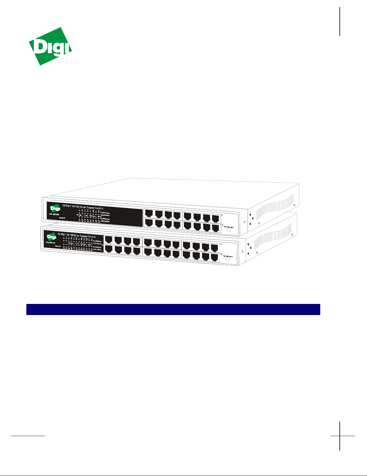
MIL-S3160
16-port 10/100
Dual Speed Switch
MIL-S3170
24-port 10/100
Dual Speed Switch
NTRODUCTION
I
Thanks for purchasing one of the MIL-S3100 family of dual speed switches. They provide dedicated bandwidths of
10/100 Mbps throughput per port to the desktop. With features such as auto-negotiation and half/full-duplex, these
switches offer smooth network migrations and eas y upgrades to network capacity.
! IEEE802.3X flow control in full-duplex operation
The MIL-S3100 family of 16 or 24 port 10/100 dual
speed switches has the following features:
! Complies with IEEE802.3, IEEE802.3U, and
IEEE802.3X standards
! 16 or 24 10/100 Mbps auto-negotiation switch ports
! Back pressure (collision based) flow control in half-
duplex operation
MS61624V01ADS
! One uplink push button is provided for cascading
! Auto-negotiation supported for each port
! Visual diagnostic LED’s supported
! 13-inch rack-mount width
! Standard IU chassis height
! Internal switching power supply
Page 2
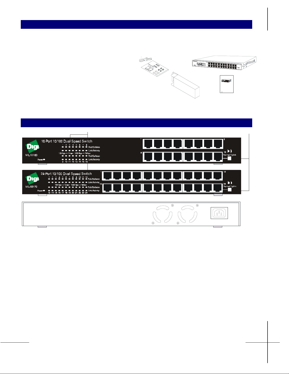
ACKAGE CONTENTS
P
Before you begin, verify that your package cont ains the
following items:
! 16 or 24-port 10/100 dual speed switch
! Self-adhesive rubber pads for desktop installation
24-Port 10/100 Dual Speed Switch
! AC Power cord
! Rack Mounting kit for rack installation
! Installation guide
Inner box
OW TO USE THE 16 OR 24-PORT 10/100 DUAL SPEED SWITCH
H
LED Display
Installation G uide
16-port 10/100M Switch
INTRODUCTION
Thanks f or yo ur pur cha se of the 16 -port Fast
One up-link connector provided for
cascadi ng
Ethernet Swit ches, pro vide d edicated
Auto-negotiation enable or force to full
100Mbp s throu ghput per po rt to the desktop.
duplex dip switche s supp orted for e ach
With features like auto-negotiation and full
port.
duplex, these sys tems offer smooth network
2Mbyt e SS RAM memo ry size
migrations an d easy upgrad es to net work
Up to 32K MAC address entries
capacity.
suppor ted
Visual diagnost ic LEDs s up port ed
1. 13-inch rack-mount wid th
The 16-po rt 10/100M Switch has th e
following features :
2. Standar d 1U ch assis hi gh t
Complies with IEEE802.3, I EEE8 0 2.3 u,
internal switchin g powe r supp ly
and IEEE802.3x standards
16 10/ 100Mbp s aut o-neg otiation swit ch
ports
Back pressure (Collision based) flow
control i n half du pl e x operat ion
IEEE 80 2.3x flow cont r o l i n f ull dupl ex
Installation G uide
Uplink push butto n
Normal/Uplink
Normal/Uplink
LED’s
The LED’s on the front panel provide visual presentation
to show the following status:
! Status of the switch’s power supply
! Connection speed of 10 Mbps or 100 Mbps
! Data activity on the segment
! Full or half-duplex operation mode
Power
Green The power is on.
Off Power is off.
Full/Col
Off There is no link or half-duplex
operation mode established and no
collision occurs.
Yellow Operation mode is full-duplex.
1
99
9
9
100-240VAC
12
Normal/Uplink
Normal/Uplink
Flashing Yellow The port is i n half-dup lex mod e and
collisions occur.
Link Activity
Off A link is not established on the port.
Green A 10 Mbps link is successfully
established on the port.
Flashing Green A 10 Mbps link is established and
data transmission or receive activity
occurs on the port.
Yellow A 100 Mbps link is established on
the port.
Flashing Yellow A 100 Mbps link is established and
data is transmitted or received.
2
Page 3

16 or 24 RJ-45 10/100 Dual Speed Switching Ports
Connecting to a Desktop
There are 16 or 24 RJ-45 ports on the front panel. The
speed and full or half-duplex modes of the ports are
automatically determined when users connect the switch
to 10Base-T and 100Base-TX devices.
The 16 or 24 RJ-45 auto-negotiation ports simplify
migration of 10 Mbps Ethernet to 100 Mbps Fast
Ethernet.
Normal/Uplink Push Button
One normal/uplink push button on the front panel allows
users to select the 16
th
or 24
th
port to connect to a PC or a
hub or switch. With this normal/uplink push button
feature, users can connect with network devices.
A link LED is lit when there is a successful connection.
The default setting is in the normal (MDI-X) position, i.e.
the long button position. The port is configured to
connect wit h a PC using a straight through twisted pair
cable.
When the push button is pressed (MDI), i.e., the short
button position, connection is made with a hub or a
switch using a straight through twisted pair cable.
The switch is connected to the desktop, to form a small
network. You can build the network as shown in the
figure.
To improve the network efficiency, it is better to have 200
Mbps full-duplex operation between the server and
switch, if the LAN adapter on the server can operate in
full-duplex mode.
Connecting to a Switch or a Hub
Switch-to-switch or switch-to-hub connections are made
by connecting the 16
th
or 24
th
port to a port or to the other
hub or switch with the normal/uplink push button pressed
in.
With 100Base-TX, the maximum network length is
approximately 205 meters with UTP cable. The maximum
length between hubs or switch-to-hub is 100 meters.
Push button in the short
position(MDI)
8
16
9
9
9
9
8
16
16
Normal/Uplink
Normal/Uplink
8
16
8
16
16
Normal/Uplink
Normal/Uplink
16-port 10/10 0 D ual
Speed Switch
Push button in the long
position (MDI-X)
3
Page 4

OUNTING KIT INSTRUCTION
M
The 16 or 24-port 10/100 Dual Speed Switch is supplied
with two mounting brackets, six screws, and four rubber
feet for mounting the rack or putting it on a flat surface.
Rack mounting in a rack
! Locate the mounting bracket over the mounting
holes.
! Insert the screw through the bracket and into the
On a flat surface
! Apply four rubber pads to the bottom of the unit.
bracket mounting holes in the switch
! Insert the unit into the 19-inch rack
! Put the switch on the flat surface.
16
8
8
16
16
Normal/Uplink
Normal/Uplink
CC COMPLIANCE STATEMENT
F
9
9
This equipment generates and uses radio frequency energy and if not installed and used properly, that is, in strict
accordance with the instructions provided with the equipment, may cause interference to radio and TV reception. The
equipment has been tested and found to comply with the limits for a Class A computing device in accordance with the
specifications in Subpart B of Part 15 of FCC rules, which are designed to provide reasonable protection against such
interference in a residential installation. However, there is no guarantee that interference will not occur in a particular
installation. If you suspect this equipment is causing inter ference, turn your switch on and off while your radio or TV is
showing interference. If the interference disappears when yo u turn the switch off and reappears when you turn the switch
on, something in the switch is causing interference.
You can try to correct the interference by one or more of the following measures:
! Plug the computer which has the equipment installed into a different power outlet so that the equipment and the
receiver are on different branch circuits.
! Reorient the receiving radio or TV antenna where this may be done safely.
! If necessary, you should consult the place of purchase or an experienced radio/television technician for additional
suggestions.
AFETY INSTRUTIONS
S
1. This product should be operated from the type of
power source indicated on the marking label. If you
are not sure of the type of power available, consult
your dealer or local power company.
2. This product is equipped with a three-wire
grounding type plug, a plug having a third
(grounding) pin. This plug will only fit into a
grounding type power outlet. This i s a safet y feature.
If you are unable to insert the plug into the outlet,
contact your electrician to replace your obsolete
outlet. Do not defeat the purpose of the grounding
type plug.
3. Do not allow anything to rest on the power cord. Do
not locate this product where persons will walk on
the cord.
4. If an extension cord is used with this product, ma ke
sure that the total ampere ratings on the products
plugged into the extension cord do not exceed the
extension cord ampere rating. Also make sure that
the total of all products plugged into the wall outlet
does not exceed 15 amperes.
5. Never push objects of any kind into this product
through cabinet slots as they may touch dangerous
voltage points or short out parts that could result in a
risk of fire or electric shock. Never spill liquid of
any kind on the product.
6. Do not attempt to service this product yourself, as
opening or removing covers may expose you to
dangerous voltage points or other risks. Refer all
servicing to servicing to service personnel’s.
4
Page 5

T
ECHNICAL INFORMATION
Standards Compatibility
ISO/IEC 802.2-3
IEEE 802.3
IEEE 802.3U
IEEE 802.3X
Interfaces
RJ-45 fully-shielded connectors for 10Base-T and
100Base-TX Fast Ethernet
Physical
Length 330mm (13 in.)
Height 43mm (1.69 in.)
Depth 230mm (9.06 in.)
Weight 2.6Kg (5.69lb)
Five-Year Limited Warranty
Digi International warrants to the original consumer or
purchaser that each of its products and all components
thereof, will be free from defects in material and /or
workmanship for a period of five years from the original
factory shipment date. Any warranty hereunder is
extended to the original consumer or purchaser and is not
assignable.
Digi makes no express or implied warrant i es including,
but not limited to, any implied warranty of
merchantability or fitness for a particular purpose, except
as expressly set forth in this warranty. In no event shall
Digi be liable for incidental or consequential damages,
costs, or expenses arising out of or in connection with the
performance of the product delivered hereunder. Digi will
in no case cover damages arising out of the product being
used in a negligent fashion or manner.
16-port 10/100 Dual Speed Switch
Input Ratings 100 to 240 VAC
50 to 60 Hz
Power consumption 23.8 W
24-port 10/100 Dual Speed Switch
Input Ratings 100 to 240 VAC
50 to 60 Hz
Power consumption 33.3 W
Environmental Specifications
Operating temperature 0° to 40°C
Storage temperature -20° to 70°C
Operating Humidity 10% to 90% RH
Storage Humidity 10% to 95% RH
Electromagnetic Emission
FCC Class A, CE Class A, VCCI Class A
Safety Approval
UL, CUL, TUV
Trademarks
Digi International and the Digi Logo are trademarks of
Digi International. All other products and brands are
trademarks of their respective holders. All rights reserved.
To Contact Digi
For prompt response when calling for service
information, have the following information ready:
• Product serial number and rev
• Date of purchase
• Vendor or place of purchase
You can reach Digi LAN technical support at
(408) 744-2751.
Or E-mail at sun-tech@digi.com
Address: 1299 Orleans Drive, Sunnyvale, CA 94089
Voice: (408) 744-2775
Fax: (408) 744-2793
E-mail: info@digi.com
Copyright 1999 Digi International
P/N 90000139 Rev A
2
Page 6

 Loading...