

Page 1
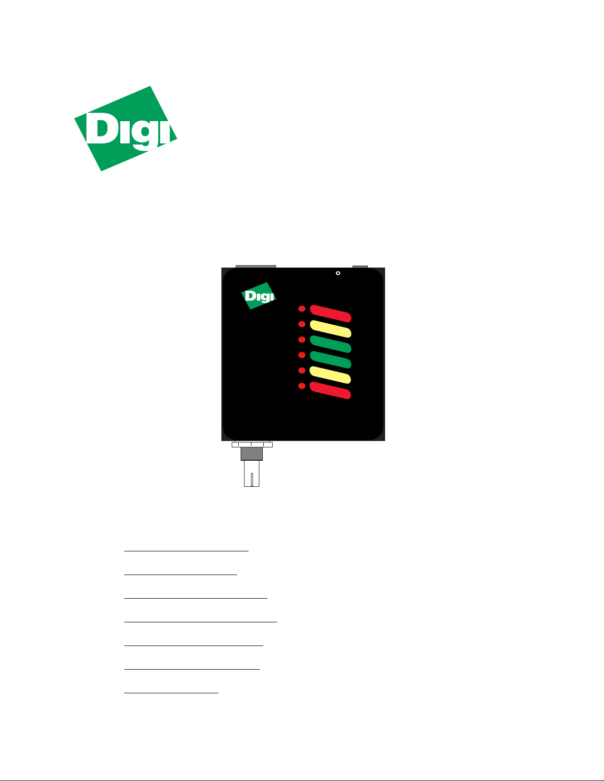
MIL-120A
Thin•Twist
COAX to 10BASE-T
Media Converter
12-20VAC
COL/TP
THIN•TWIST
Model MIL•120A
COAX to 10BaseT
CONVERTER
Ethernet / IEEE 802.3
FCC PART 15 CLASS A COMPLIANT
RCV/TP
LINK
POWER
RCV/CX
COL/CX
Installation Guide
This guide includes the following information:
“Installation” on page 2
“Link Test” on page 2
“Disabling Link” on page 2
“Diagnostic LEDs” on page 3
“Configuration” on page 3
“RJ-45 Pinouts” on page 3
“Legal” on page 4
Doc #: 75140 Rev. D
Page 2
Install Guide
Installation
Do the following to install the MIL-120A:
1. Attach a UTP cable from the network to the MIL-120A's RJ-45 port
2. Attach a T-type BNC connector from the network cabling to the BNC
connector
3. Connect the power adapter's cord from the power source to the unit
Note:
Use shielded twisted pair (CAT 5) cabling for CISPR 22 B installation.
Link Test
The MIL-120A provides a
MIL-120A ships with the
Link
test function, which is a 10BASE-T standard. The
Link
function test “enabled”—only pin one jumpered
with a jumper block. This allows the LEDs to illuminate when there are links.
Disabling Link
To disable the
Link
test:
1. Use a Phillips-head screwdriver to remove the four Phillips-type screws
located on the sides of the unit
2. Remove the BNC nut and its washer
3. Slide the housing off, over the BNC connector
Link
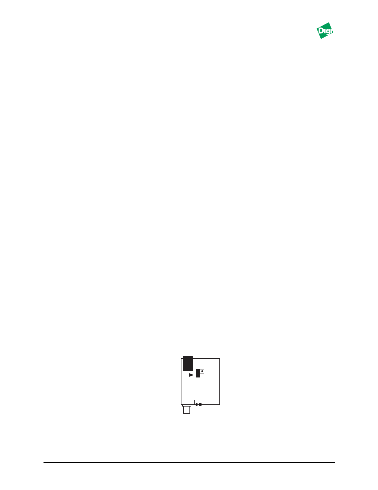
4. Locate the two-pin
jumper (Figure 1)
5. Place the jumper block onto both pins
6. Reassemble the unit (reverse steps 1 through 3)
Note:
Model: MIL-120A 2
The MIL-120A operates in a “StarLAN-10” environment when
Power and Link LEDs Illuminate.
Link Test
Enabled
Figure 1.Link and DIP Switch Locations
LINK
1 2
DIP Switch
Link
is disabled. Only the
Page 3

Install Guide
Diagnostic LEDs
COL/TP: Collisions are occurring on the 10BASE-T network
RCV/TP Unit is receiving packets from the 10BASE-T network
Link:
Power:
There is an active connection to a10BASE-T hub (or another node)
when
Link is enabled
Unit is receiving power
RCV/CX Unit is receiving packets from the 10BASE2 network
COL/CX: Collisions are occurring on the 10BASE2 network
Configuration
Next to the COAX cable connector, there is a DIP switch that control the 50 ohm
termination resistor (Figure 1). These switches support a variety of configurations.
Both switches are shipped in the UP position (default). Other configurations
include:
If the MIL-120A is connected to the end of a multi-node segment without a Tconnector and terminator, enable the 50 ohm resistor by:
• Placing switch 1: UP and
• Placing switch 2: DOWN
If the MIL-120A is connected to a single-node “without” a T-type connector and
terminator on a COAX cable of less than one meter’s length:
• Place both switches (1 and 2) in the DOWN position
Note:
For this configuration, you do not need a 50 ohm terminator on the COAX segment of the
MIL-120A's BNC connector.
RJ-45 Pinouts
4
5
3
2
1
6
7
8
MDI
Pin 1=TX+
Pin 2=TX-
Pin 3=RX+
Pin 6=RX-
Follow these guidelines when connecting the 10BASE-T Port:
• For a Hub or a Repeater, use a straight-through cable (where the pins are
connected 1 to 1, 2 to 2, 3 to 3, and 6 to 6)
• For a Workstation/PC port, use a swap cable (where the pins are connected 1
to 3, 2 to 6, 3 to 1, 6 to 2)
Figure 2. RJ-45 Pinouts
Model: MIL-120A 3
Page 4

Legal
Regulatory Approvals
• FCC Class A
• UL 1950
• CSA 22 No. 950
• EN60950
• CE
– EN55022 Class B
– EN50082-1
Canadian EMI Notice
This Class A digital apparatus meets all the requirements of the Canadian Interference-Causing
Equipment Regulations.
Cet appareil numérique de la classe A respecte toutes les exigences du Règlement sur le matériel
brouilleur du Canada.
European Notice
Products with the CE Marking comply with both the EMC Directive (89/336/EEC) and the Low Voltage
Directive (73/23/EEC) issued by the commission of the European Community. Compliance with these
directives implies conformity to the following European Norms:
• EN55022 (CISPR 22) - Radio Frequency Interference
• EN50082-1 (IEC801-2, IEC801-3, IEC801-4) - Electromagnetic Immunity
• EN60950 (IEC950) - Product Safety
Digi International warrants to the original consumer or purchaser that each of its
products, and all components thereof, will be free from defects in material and/or
workmanship for a period of five years from the original factory shipment date. Any
warranty hereunder is extended to the original consumer or purchaser and is not
assignable.
Digi makes no express or implied warranties including, but not limited to, any implied
warranty of merchantability or fitness for a particular purpose, except as expressly set
forth in this warranty. In no event shall Digi be liable for incidental or consequential
damages, costs, or expenses arising out of or in connection with the performance of the
product delivered hereunder. Digi will in no case cover damages arising out of the
product being used in a negligent fashion or manner.
To Contact Digi
For prompt response when calling for service information, have the following information ready:
• Product serial number and rev.
• Date of purchase
• Vendor or place of purchase
Reach Digi Technical Support at 408/744-2751
Or E-mail at “sun-tech@dgii.com”
Address: 1299 Orleans Drive
Sunnyvale, CA 94089
Voice: 408/744-2775
Fax: 408/744-2793
E-mail: info@dgii.com
Five-Year Limited Warranty
Doc #: 75140 Rev. D
 Loading...