

Digi II series, Digi II 8.0, Digi II 6.0, Digi II 4.5 Installation & Operation Instructions
Page 1

"Digi II" Series Heater Installation & Operation Instructions
Digi II SAUNA HEATERS and CONTROL
Models 1714-450-1705, 1714-600-1705,
1714-800-1705 (With Control 1601-12)
Read all instructions carefully before installation. Please
leave all instructions and warranty with the owner.
WARNING
Do not take a sauna if using
alcohol, drugs or
medications.
Pregnant women or persons
with poor health should
consult their physician
before using any sauna.
Caution fire hazard: Do not
use the sauna room for
drying clothes, bathing
suits, etc. Do not hang
towels above heater or place
any object other than the
rocks supplied on the
heater. If any darkening of
the wall around the heater
is noticed discontinue sauna
use immediately.
WARNING
Prolonged exposure to elevated temperatures is capable of inducing
hyperthermia. Hyperthermia occurs when the internal temperature of
the body reaches several degrees above the normal body temperature
of 98.6°F. The symptoms of hyperthermia include an increase in the
normal temperature of the body, dizziness, lethargy, drowsiness, and
fainting. The effects of the hyperthermia include failure to perceive
heat, failure to recognize the need to exit the room, unawareness of
impending hazard, fetal damage in pregnant women, physical inability
to exit the room and unconsciousness.
WARNING
The use of alcohol, drugs, or medication is capable of greatly
increasing the risk of fatal hyperthermia.
SECTION 1: GENERAL INFORMATION
These heaters are UL approved for permanent installations and
electrical connections. Built with splash proof construction, the
conducting parts are protected against water. All wiring must be
performed in accordance with local codes. See Diagram 4 for wire and
room size requirements.
Inspect sauna regularly for
required maintenance to
heater, control and benches.
Replace wood surfaces
which show any signs of
deterioration.
The heater gets extremely
hot during operation and
should not be touched or
burns may result.
Minors should be
adequately supervised
whenever near a hot or
warming sauna.
These heaters are wall mounted, 18¾" W x 11" D x 24¼" H, with wall
mounted controls.
Page 2
"Digi II" Series Heater Installation & Operation Instructions
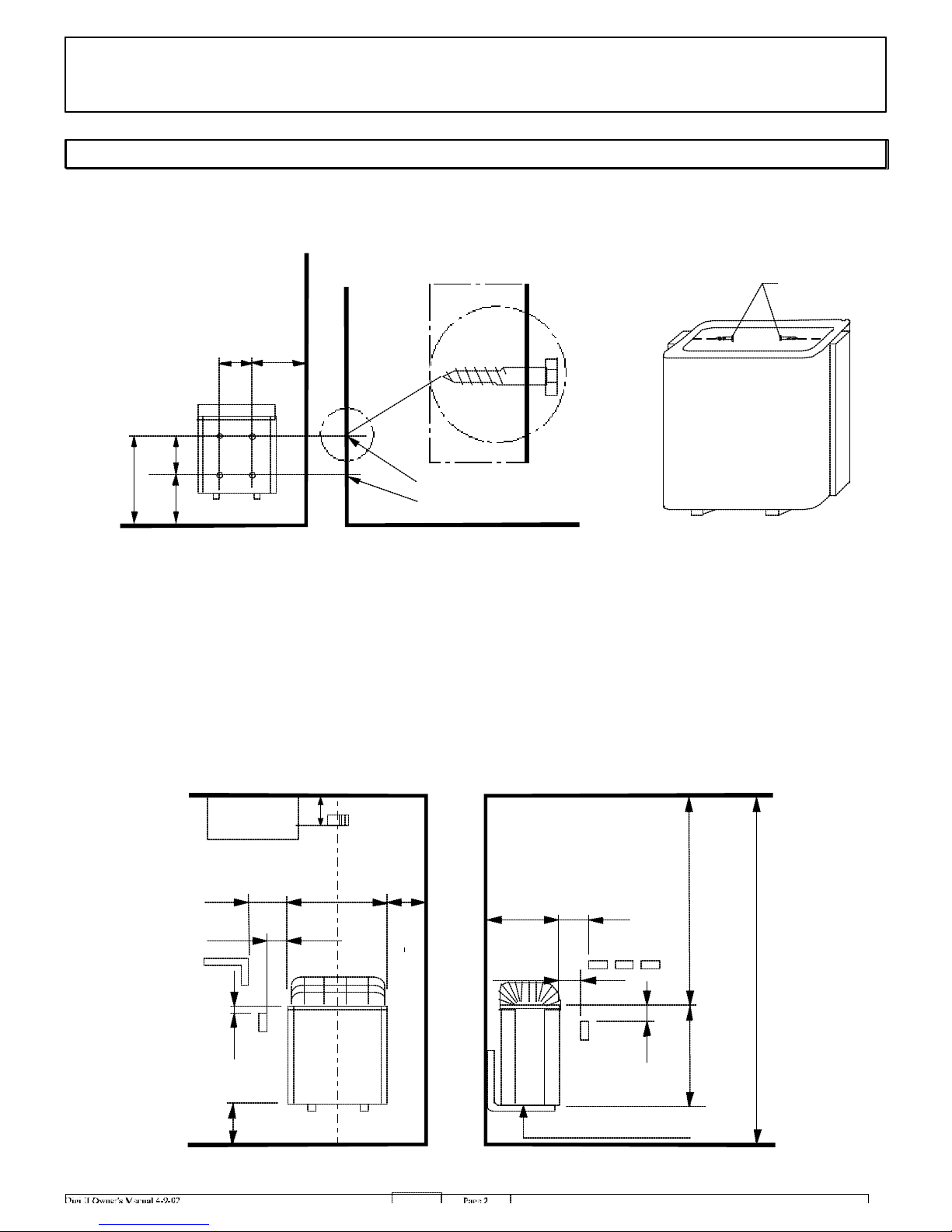
DIAGRAM 1
MOUNTING BRACKET LOCATION AND MINIMUM DISTANCE TO COMBUSTIBLE MATERIAL
Use the long screws in
the upper holes of the
mounting bracket
Screws
K
7/8
5
"
11"
Table 1
11"
B
Screws
Temperature
Sensor
A
2"
1
18
1/2
1"
1/2
6
"
3/4
"
A
12"
D
45"
"
19
7/8
75"
"
1
1/2
"
1"
High Limit Control
Page 3
"Digi II" Series Heater Installation & Operation Instructions
SECTION 2: MOUNTING OF SAUNA HEATER
HANGING THE HEATER Using the template provided, drill four
9/64" holes to fasten the heater brackets to the wall. Install two ¼" x 1
½" hex head lag screws (supplied with the heater) through the top holes
on the mounting brackets (one screw per bracket). Tighten these
screws. The screws must be threaded through the wall into a framing
member or backing board to support the heater weight. Locate the two
¼" x 1" hex head lag screws (supplied with the heater) then install them
into the two lower mounting holes. Tighten to lock the heater brackets
in place.
Place the heater on the wall brackets and fasten with screws. See
Diagram 1 & 2 for the heater location details and the necessary
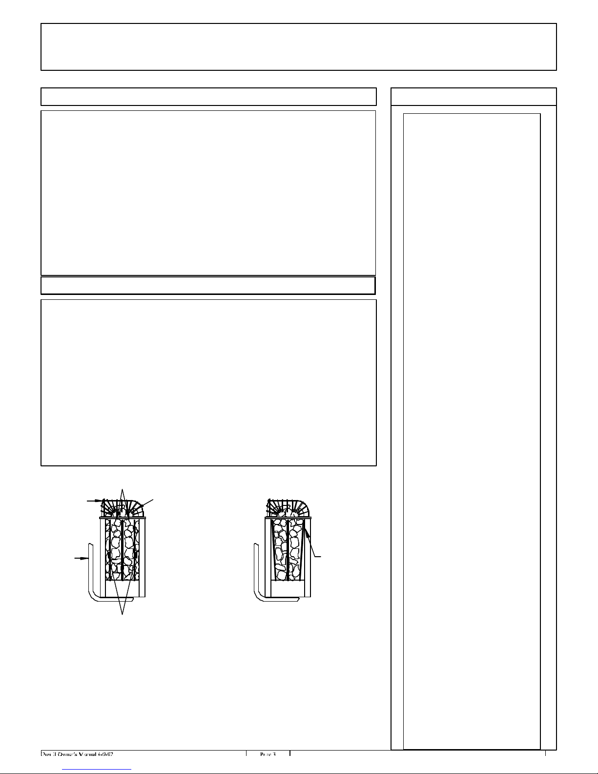
SECTION 3: PLACING OF ROCKS
The rocks supplied with the heater have been chosen to provide the best
heater performance. Use of any other type of rock may void the heaters
warranty. Never operate the heater without rocks in place!
Rinse the rocks with water before placing in the heater. Packing the
rocks too tightly may cause the heater high limit switch to trip. Follow
the below rock placement instructions. After completion, attach the
guard with the screws provided.
On a yearly basis, remove all rocks, clean rock fragments, and reinstall
reusable rocks. Follow the directions below for placement and the
High Limit
Sensor
a. Loosely place rocks between
the elements so air flow is not
restricted.
c. Loosely cover the tops of
all elements a minimum
of 2" to 3".
Incorrect Placement
of Rocks
WARNING
Fire sprinkler systems used
inside any sauna room
should be properly rated for
sauna room temperatures.
Do not pour chlorinated
pool or spa water on heater.
Excessive water use on
heater may cause damage
and void warranty.
Do not install a shower in
the sauna room.
Electric Shock Hazard -
High voltage exists within
this equipment. There are
no user serviceable parts in
this equipment. All
installation and service to
this equipment should be
performed by qualified
licensed personnel in
accordance with local and
national codes.
Do not construct sauna
room so as to restrict air
flow through the bottom of
the heater.
Wall mounting
bracket
b. Rocks must be placed between the
elements and the wall of the rock compartment.
1. Put smaller rocks in first around the outer perimeter of the heating chamber.
2. Completely fill all four sections (front, 2 center sections between elements,
and back). In the outer sections, use smaller rocks placed more tightly (see note b).
3. Place rocks loosely in the center 2 sections (see note a).
4. Be sure rocks complete cover the elements (see note c).
Rocks between
the front element
and the outer wall
will reduce cycling
of the heater.
Packing the rocks too
tightly may cause the heater
high limit switch to trip.
Page 4

"Digi II" Series Heater Installation & Operation Instructions
Floor Area
Height
Cu. Ft.
Height
Cu. Ft.
N+Gr
N+Gr
PHASE
VAC
AMPS
HEATER
kW
MINIMUM ROOM
MAXIMUM ROOM
DIAGRAM 2 DIAGRAM 3
HEATER MODEL
Product Number
Digi II 4.5
1714-450-1705
Digi II 6.0
1714-600-1705
Digi II 8.0
1714-800-1705
DIAGRAM 4
Ceiling
4.5 16 sq. ft. 75"
6.0 28 sq. ft. 75" 175 96" 310
8.0 40 sq. ft. 75"
Volume
Ceiling
100 96" 210
250 96" 425
Volume
1 208 21.6
1 240 18.8
3 208 12.5
3 240 10.8
1 208 28.8
1 240 25
3 208 16.7
3 240 14.4
1 208 38.5
1 240 33.3
3 208 22.2
3 240 19.2
WIRE
SUPPLY TO
2 #10 AWG +
N+Gr
2 #10 AWG +
N+Gr
2 #12 AWG +
N+Gr
2 #12 AWG +
N+Gr
2 #8 AWG +
2 #8 AWG +
N+Gr
3 #12 AWG +
N+Gr
3 #12 AWG +
N+Gr
2 #8 AWG +
N+Gr
2 #8 AWG +
3 #10 AWG +
N+Gr
3 #10 AWG +
N+Gr
Page 5
"Digi II" Series Heater Installation & Operation Instructions
SECTION 4: ELECTRICAL HOOK-UP
Electrical installation must be made by a licensed electrician in
accordance with the National Electrical Code and local regulations.
Remove the painted cover from the side of the heater . Route the feed
wires through the holes provided in the bo ttom of the heater and
connect the wires to the appropriate labeled wires. To determine the
correct wire size, refer to Diagram 4. Use copper supply wire only,
suitable for minimum 90 degrees C. The heater must be grounded! See
Diagram 5 f or proper connections.
SECTION 5: HEATER SCREEN (GUARD RAIL)
Install a wooden heater guard to prevent the sauna bather from
accidentally touching the sauna heater. Install the heater guard rail
with the height clearances and dimensions shown in Diagram 7.
SECTION 6: OPERATION
WARNING
Do not locate benches over
heater. Minimum clearance
of ceiling above heater 45".
For minimum clearance
from heater to wooden
surfaces refer to Diagram 1
for distances. The mounting
brackets supplied provide
the proper clearance from
the heater to the wall.
Use only copper wire of the
size and type indicated in
the Heater Specification
Chart and the temperature
rating indicated on the
heater junction box.
The control for this heater has a thermostat to adjust the sauna
temperature and a timer to control when the heater starts and stops. The
maximum the timer will allow the heater to operate is 60 minutes. For
health and fire safety, never attempt to alter or bypass the timer or
thermostat.
The Digi II (1601-11) Control should be mounted outside the room.
The control has 16ft control wire supplied. The maximum control wire
length would be 90ft.
The sensor should be mounted over the heater 2" from the ceiling and
connected to the circuit board on terminals 2 and 3. See
Control Overview
Alarms
thermostat sensor and or wire. The control will display "heat sensor
cable cut". During the alarm the control will turn power off to the
heater and the display will remain on the control. Rectify the fault
situation and recycle power to heater. If problem persists refer to
Section 13.
The control is equipped with an alarm that indicates a faulty
Diagram 1
All heaters and controls
must be grounded per NEC
to prevent electrical shock
in case of unit failure.
Electrical outlets or
receptacle must not be
installed in a sauna room.
A guardrail or fence is
required around the heater
to prevent burns from
accidental contact.
Locking Key Pad
in the Off mode, press the up arrow key and then
key. "Locked" will be displayed. This will make all key inactive until
the control is unlocked.
The control keypad can be locked. With the control
press
the down arrow
Page 6

"Digi II" Series Heater Installation & Operation Instructions
DIAGRAM 5
For use input Power input 208-240V Ac 1ph 60Cyc Power input 208-240V Ac 3ph 60Cyc
with kw Copper wire size Copper wire size
1714-450-1705 4,5 2xAWG 10+N+Gr 3xAWG 12+N+Gr
1714-600-1705 6,0 2xAWG 8+N+Gr 3xAWG 12+N+Gr
1714-800-1705 8,0 2xAWG 8 +N+Gr 3xAWG 10+N+Gr
1714-450-1705 4,5 2xAWG 10+ N+Gr 3xAWG 12+N+Gr
1714-600-1705 6,0 2xAWG 8 +N+Gr 3xAWG 12+N+Gr
1714-800-1705 8,0 2xAWG 8 +N+Gr 3xAWG 10+N+Gr
heater to heater to heater
354 SKSO 25 F
240V 208V
240V 208V
Heater Input Heating elements
SEPC 93
Type
1714 - 450 - 1705
1714 - 600 - 1705
1714 - 800 - 1705
K3 K1
1
3 7
2
4 6 8
1 2 3 4 5 6 N
Gr
A2
5
A1
kW
4,5
6,0
8,0
B
F
Cont
P1
1 2
1500W
1,2,3
K2
L N Light Fan
P2
P3
3
Light Fan
Heater
208V or 240V
SEPC 94
2000W
1,2,3
J3 A B
1 2 1 2 3 4 5 1 2 3 4 5
Control panel
Sensor
SEPC 95
2670W
1601-11
1,2,3
(194
O
F)USE COPPER WIRE ONLY.
Gr
The electrical installation
must be made by a licensed
electrician in accordance
with local regulations.
CAUTION-USE SUPPLY WIRES
SUITABLE FOR AT LEAST 90
1 2 3 4 5 6
N
3 ph
Gr N T1 T2 T3
1 2 3 4 5 6
N
1 ph
O
C
Gr
Gr N T1 T2
IMPORTANT: A neutral wire is required to operate the control. The electrical installation must be
made by a licensed electrician in accordance with local regulations.
Use 14-2 with ground wire for the fan and light.
CAUTION-USE SUPPLY WIRES SUITABLE FOR AT LEAST 90°C (194°F) USE COPPER WIRE
ONLY.
Page 7

"Digi II" Series Heater Installation & Operation Instructions
SECTION 6: OPERATION, CONTINUED
Memory / User 1
Memory / User 2
Memory / User 3
Memory / User 4
Increase
Decrease
On/Off
Temperature
Delayed Start Time
Sauna Length
Light
Fan
Control Setup:
This setup has
6 different menus.
To escape from this Setup Menus, press the On/Off button or the device will automatically exit the menu in
approx. 4 seconds.
To enter the Setup Menu press PROG/OK button and hold down for approx. 3 seconds until the following
appears in the display:
MENU 1
TIME: 12:00
Setting the Clock: Press the up arrow and hold down: The minutes and hours will begin to change. When
the hour reads the correct time, release the up arrow key and enter minutes by repeatedly pressing the arrow
key for each minute. Press PROG/OK to save the time in memory.
Next will display:
MENU 2
LANGUAGE: ENGLISH
Setting Language: Press the up or down arrow key repeatedly until the language you desire appears in the
display. Press PROG/OK to save in the Language in memory.
Page 8

"Digi II" Series Heater Installation & Operation Instructions
SECTION 6: OPERATION, CONTINUED
Next will display:
MENU 3
OFFSET: T1 0C
Using the arrow keys, select the calibration value (0 +/-10C).
Example: After reading the temperature on the thermometer in the sauna, you noticed that the temperature
reading in the display is 4C higher. Set Offset T1 to -4C to get the displayed temperature to match the
thermometer. (This offset does not change the actual temperature, this is just for indication only.) Press
PROG/OK: to save the calibration value.
Next will display:
MENU 4
SMARTSAUNA: OFF
Using the arrow keys, select ON or OFF Press PROG/OK: to save the setting.
Note: SmartSauna measures the temperature in the sauna, and based on this information, the control will
determine the length of time needed to heat the sauna to the set value. This function is only available in
timer mode.
Next will display:
MENU 5
CLOCK: 24 h
Using the arrow keys, select a 12 or 24-hour clock. If a 12-hour clock is selected, AM or PM will appear in the
display after the time. Press PROG/OK: to save the setting.
Next will display:
MENU 6
TEMPERATURE: C
Using the arrow keys, select the desired temperature scale. ( Celsius or Fahrenheit) Press PROG/OK: to save the
setting.
Programming Memory (User buttons)
Press ON/OFF and the greeting appears in the display and the backlight comes on. Next press PROG/OK and
the following will appear in the display: The first number indicates start time, the length of sauna, and the last
is desired temperature.
17:30 01:00 The maximum the timer will allow the heater to operate is 60 minutes.
50C
Note!
option.
The start time reading in the display is not saved in the memory slots. Time delay is not a memory
Press the
Sauna Length: 01:00 The duration can now be set using the arrow keys. When the desired time
has been selected, press PROG/OK to return to previous screen.
Sauna Length
button and the hours and minutes (hh:mm) will appear in the display.
Page 9

"Digi II" Series Heater Installation & Operation Instructions
SECTION 6: OPERATION, CONTINUED
Programming Memory (User buttons) continued...
Press the TEMPERATURE button and the temperature value will appear in the display current
temperature setting: 50C The temperature can now be set using the arrow keys. When the desired
temperature has been selected, press PROG/OK and the display will return to the previous screen.
To save the values to memory, press the memory buttons 1. The display will now read:
PROGRAM1
01:00 50C
Press PROG/OK once again to return the display to 17:30 01:00
50C .
To program another memory button go back to the beginning of Programming Memory (user buttons). Press
ON/OFF to exit the programming mode.
Review
buttons.
Setting Time Delay without Saunasmart:
The control is in the Off mode:
Press
Press PROG/OK and the following will appear in the display start time, sauna length, and temperature.
17:30 01:00 The maximum the timer will allow the heater to operate is 60 minutes.
90C
Press Time Delay button and the hours and minutes (hh:mm) will appear in the display.
START:
12:00
The start time can now be set using the arrow buttons. When the desired time has been selected, press
PROG/OK and the display will return to the previous screen.
Press the Sauna Length button and the hours and minutes (hh:mm) will appear in the display.
Sauna Length : 01:00 The duration can now be set using the arrow keys. When the desired time
has been selected, press PROG/OK to return to previous screen.
When the device is in Off mode, you can review your programmed values by pressing the memory
ON/OFF
and A greeting appears in the display and the backlight comes on.
Press the TEMPERATURE button and the temperature value will appear in the display current
temperature setting: 50C The temperature can now be set using the arrow keys. When the desired
temperature has been selected, press PROG/OK and the display will return to the previous screen.
Press PROG/OK and hold down for about 3 seconds until the following appears in the display:
15:00
17:30 SAUNA
15:00 is the current time and 17:30 is the start time, when the sauna is automatically turned on.
Page 10

"Digi II" Series Heater Installation & Operation Instructions
SECTION 6: OPERATION, CONTINUED
Setting Time Delay with Saunasmart:
Saunasmart means choosing the time to enter the hot room, not the time to turn the heater on. The system will
calculate when to turn on in relation to entry time. The control will be able to determine how long the system
needs to run to reach set temperature. This function usually takes 3 heat cycles to get time versus temperatures
memorized.
The entire programming process is the same as "Setting Time Delay without Saunasmart" except for the final
step of programming display.
15:00
17:30 SMART
is the current time and
15:00
17:30 is the time the room is ready to enter
.
Everyday Setting:
If you want to take a sauna every day at the same time, do the following:
Press
PROG/OK
17:30 01:00 The maximum the timer will allow the heater to operate is 60 minutes.
90C
Press PROG/OK and hold down for about 3 seconds until the following appears in the display:
15:00
17:30 SMART (or Sauna depending on what delay mode is selected)
is the current time and
15:00
Daily Operations of Memory (User buttons):
Press ON/OFF and the greeting appears in the display and the backlight comes on.
Press the appropriate button to start operation of the Light and Fan ; press again to shut off. The
corresponding symbols will appear in the display.
Press Memory Button 1 - 4: The system will turn on and operate until program has expired. The control will
then turn off.
. The following will appear in the display start time, duration and temperature.
17:30 is the time the room is ready to enter
.
Daily Operations Using Time Delay Functions:
Press ON/OFF and the greeting appears in the display and the backlight comes on.
Next press PROG/OK and the following will appear in the display start time, duration and temperature.
17:30 01:00 The maximum the timer will allow the heater to operate is 60 minutes.
90C
If all information is correct: Press PROG/OK and hold down for about 3 seconds until the following appears
in the display: Leave the control on and return when system is ready.
15:00
17:30 SMART (or Sauna depending on what delay mode is selected)
If the control settings are not correct, go to the " Setting Time Delay" portion of the manual to program
control and then return to portion when completed.
Page 11

"Digi II" Series Heater Installation & Operation Instructions
SECTION 7: HIGH LIMIT CONTROL (RESET BUTTON)
The sauna heater has a built-in high limit control, which automatically
turns off the heater if the temperature inside in the sauna room rises to
an abnormally high level.
To restart the heater, let the heater cool and turn the timer down to off,
then push the reset button on the bottom of the heater, See the last
drawing on Diagram 9 on page 14. If the high limit continually shuts
off the heater, refer to Section about Troubleshooting.
SECTION 8: HOW TO TAKE A SAUNA
• When taking a sauna, allow time to relax completely.
• Remove clothing and jewelry...if required, wear a towel loosely.
• After 10 minutes or when perspiration begins, leave sauna and relax
in dressing area...follow with a cool shower.
• Cooling time should equal time spent in sauna. Enter sauna room
again and stay 5 or 10 minutes.
• Repeat the cycle 2 or 3 times; end with a brisk shower...rinse in cool
water.
• Dress when completely dry and perspiration has stopped.
• Some sauna bathers enjoy the soothing effect of steam by splashing
water on the heated sauna rocks. Use only one dipper full (approx. ½
cup) at a time and take care to keep clear of the steam as it rises off
the rocks.
• Do not smoke, exercise or drink alcoholic beverages in the sauna
room.
• Do not pour chlorinated pool or spa water on the heater or corrosion
Shower
Sauna (10 - 15 min.)
Shower or swim
Rest (10 - 15 min.)
Relax with juice or water
Like it?
Do it again and
feel great.
Page 12

"Digi II" Series Heater Installation & Operation Instructions
DIAGRAM 6
TYPICAL PRE-CUT WALL CONSTRUCTION
2x4" framing
fiberglass insulation
foil vapor barrier
T&G soft wood
1/2" wallboard
1/2" wallboard
DIAGRAM 7
HEATER SCREEN (GUARD RAIL)
min 1 ½ "
min 1 ½ "
min 1"
Heater Screen
(guard rail)
DIAGRAM 8
VENTILATION
Locate vent under
the top bench
DIAGRAM 9
RESETTING HIGH LIMIT SWITCH
High Limit Control
Electrical Connections
Page 13

"Digi II" Series Heater Installation & Operation Instructions
SECTION 9: WARNING PLACARDS
Two metal placards are included in the Installation Instruction
Envelope packaged with every Sauna Heater. The CAUTION placard
must be attached to the interior wall of the sauna room directly above
the heater where it is visible to the bather. The WARNING placard
must be attached to the door of the sauna room.
SECTION 10: ROOM CONSTRUCTION
For safety and reliability, the following rules must be addressed.
• No permanent locking or latch system is to be used on the sauna door.
• Acceptable door fittings are: magnetic catches, friction catches,
spring or gravity loaded closures. The door must always open
outwards.
• The warranty is void if a shower is installed in a sauna room.
• No electrical receptacle shall be installed inside the sauna room.
• The enclosed WARNING: Reduce the risk of overheating …
warning plate must be mounted on or alongside the door outside the
sauna room at about eye level.
• The enclosed CAUTION: Reduce the risk of fire … caution plate
must be mounted on the interior wall above the heater.
• The heater should not be operated without its container properly filled
with rocks and the rock guard in place.
• If an intercom speaker is installed, it should be away from the heater
and as close to the floor as possible.
• If a room light is installed, it should be a surface mounted bracket
type. Wall mounted lights should be about 70" above the floor.
Ceiling mounted lights should be of an approved type with a junction
box that is remote to the fixture itself. Use only a fixture that uses
A.F. or fixture type internal wiring. A 60 watt bulb should provide
sufficient lighting.
• Fire sprinkler systems installed inside any sauna room should be
properly rated for sauna room temperatures.
WARNING
The "CAUTION" and
"WARNING" placards
must be mounted in
accordance with Section 9.
For safety purpose sauna
door must open out and not
lock.
Never use a wood stain, seal
or preservative on the inside
of your sauna room.
Light fixtures get very hot
during operation. Locate
light fixture where it will
not be a burn hazard.
Page 14

"Digi II" Series Heater Installation & Operation Instructions
SECTION 11: VENTILATION
VENTILATION should be changed about 6 times an hour. This can be achieved by making a vent opening
(fresh air inlet) in the sauna wall directly below the heater. The air outlet must be lower than the upper
benches, as far as possible from the heater and about two feet higher than the fresh air inlet vent,
See Diagram 8.
The minimum opening should be determined using one of the following formulas:
For R<31, V≥9.3
For R≥31, V≥0.3R
where R = the floor area of the room in square feet and
V = the minimum vent size in square inches
SECTION 12: MAINTENANCE
The sauna, like a bathroom, should be kept clean and odor free.
Towels or mats should always be used on benches and floor as perspiration otherwise penetrates the soft
wood.
Air out the sauna often by keeping the door and vents open when the sauna is not in use. Saunas that are in
daily use should be washed down at least once a week to keep them clean and the air fresh. Duckboard should
be removed from the sauna, the sauna floor mopped and dried in a conventional manner, and the duckboard
thoroughly scrubbed and dried before returning to the sauna room. The sauna heater should be wiped down
occasionally with a damp cloth to remove lint and dust. The rocks should be removed once a year for cleaning
and small or crumbled rocks replaced.
To clean and remove perspiration stains, use soap or detergent in warm water, best applied with a scrub brush.
Badly soiled surfaces may require sanding. Sand paper wrapped around a wooden block works well.
Benches and supporting structure must be inspected annually for potential deterioration due to age, dry rot or
abuse. Any boards with signs of deterioration should be replaced immediately to avoid possible injury.
SECTION 13: TROUBLESHOOTING
For troubleshooting or service questions call 1-888-780-4427 and ask to speak with service. Prior to calling
please have the Model & Type # available.
sales@saunatec.com
techsupport@saunatec.com
 Loading...