

Page 1
®
Hubport
USB HUB
Installation
Guide
Models:
Hubport/4
Hubport/7
/c Models:
Hubport/4c
Hubport/7c
Hubport/4c DC
Hubport/7c DC
www.digi.com
Page 2

Table of Contents
Table of Contents ............................................................. 1
Introduction to Hubs ........................................................ 1
Connecting Your Hubport................................................ 2
Installing Hubport Drivers ............................................... 3
Interpreting the System Status Light................................ 3
Regulatory & Other Information...................................... 4
Page 3
Introduction to Hubs
Thank you for purchasing the Hubport, a self-powered Universal Serial Bus (USB) hub designed to provide a
convenient and effective means of bringing USB connectivity to your PC, server, or laptop. The Hubport also
delivers the potential of Digi International’s Edgeport USB to Serial (RS-232) expansion module.
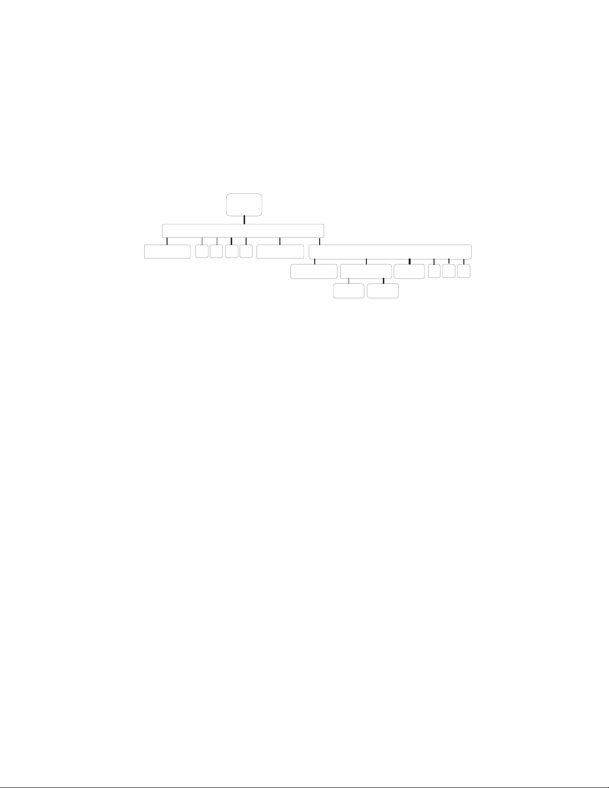
Hubs, critical components in the USB architecture, are wiring concentrators that enable the attachment of multiple
devices, thus converting a single attachment point into multiple attachment points. USB architecture allows a
cascaded multiple hub configuration with certain power limitations (explained later in this section). See figure 1.
PC
Host
Hubport
Edgeport Edgeport
Edgeport
Figure 1: Example of a Typical Hub Configuration
Hubport
bus-powered hub
joystick mouse
scanner
Each hub has an upstream port, connecting to the host, and multiple downstream ports, connecting to downstream
devices, possibly including other hubs. A hub can detect attachment and detachment of downstream devices and
enable and monitor the distribution of the power to downstream devices via their integral hardware and the operating
system.
Each USB device reports its power requirements to the operating system, which then enables and disables the device
as a function of its power requirements and the amount of available power. High powered devices typically need to
be connected to a self-powered hub, such as the Hubport, which obtains power from its external power supply and
provides up to 500 mA for each downstream port. Only low powered devices, such as a mouse, can be connected to
a bus-powered hub, which obtains power from its upstream host and provides up to 100 mA for each downstream
port.
Due to the limited available power for bus-powered hubs, cascading two bus-powered hubs is an illegal topology,
and devices connected to the second hub will not function. USB specifications limit the connection of a bus-powered
hub to a self-powered hub or host only. All Hubports, except the Hubport/4c in bus-powered mode, operate as selfpowered hubs, and are not affected by this limitation.
According to the USB Specification, the maximum limit of hubs cascaded in series cannot exceed five. In other
words, you may have a maximum of five hubs between any device and the host. This does NOT mean that the
maximum number of hubs in a system is five. Indeed, up to seven hubs can be connected parallel at any given level.
You must tally both external and embedded hubs when counting downstream hubs.
Hubport Installation Guide (90000664 Rev. B) – Page 1
Page 4

Specifications
USB2.0
Product
Hubport/4 No
Hubport/4c Yes
Hubport/4c DC Yes
Hubport/7 No
Hubport/7c Yes
Hubport/7c DC Yes
High
Speed†
Powering
Method
Self*
Self*
USB Bus
Self*
Self*
Self *
Self*
USB
Downstream
Ports
4
4
2 None
4
7
7
7
Variable 10 - 28VDC @15W
Variable 10-28DC @24W
Power
Requirements
5VDC @2A
5VDC @2A
5VDC @3A
5VDC @3A
Connecting Your Hubport
Type A Type B
Note that Windows NT 4.0 users must install the drivers before connecting a Hubport. To connect the cables
included with your Hubport:
1) Plug one end of the power supply* into the back of your Hubport and the other end into an AC outlet.
2a) To connect your Hubport to a PC, plug the Type A end of the USB cable into one of the PC’s USB Type A
slots and the Type B end of the USB cable into the back of the Hubport.
OR
2b) To connect a standard USB device to your Hubport, plug the Type A end of the USB cable into the Hubport
and the Type B end into the device.
† USB 2.0 High Speed is not supported by Windows 98.
* Power to this product may be supplied by a UL Listed Direct Plug-In Power Unit marked “Class 2” with a minimum rating listed in
the Specifications table above if used in the U.S. and Canada or a power supply with similar rating and approved by your local
safety code if it is used elsewhere.
1. Some units may be equipped with a pigtail connection. Follow the polarity markings on the cable.
2. For polarity on Hubports with a threaded locking connector, use center positive as follows:
3. For polarity on all other Hubports, use the following:
Hubport Installation Guide (90000664 Rev. B) – Page 2
Page 5

Installing Hubport Drivers
For Windows 98, 2000, and XP Users
After following the instructions described in “Connecting Your Hubport” in the previous section, installation will be
complete.
For Windows NT 4.0 Users
Because Microsoft does not support USB in NT4.0, Digi International supplies a set of USB drivers that will be
installed along with the necessary Hubport drivers. NOTE: You must install the drivers using an account that has
administrative privileges!
To install the USB stack and Hubport drivers:
1) Insert the “Edgeport Driver” CD Version 2.60 or above into your CD-ROM drive.
2) When the welcome dialog appears, click the Install Driver button.
Once the driver installation program has begun, follow the on screen instructions.
3a) If you are installing drivers for the first time: An Information dialog informs you that the installation was
successful. After clicking OK, the installation is complete.
3b) If you are replacing existing Edgeport drivers: Follow the on-screen instructions. Note that, before beginning
the installation of the drivers, all applications with open ports must be closed and all USB devices unplugged. If
you close all the applications and unplug all the USB devices, then you will not need to reboot for the new drivers
to take effect immediately. If any applications are left open or USB devices plugged in, you may choose to abort
the installation or to continue and be required to reboot before the upgrade can take effect.
Follow the instructions described in “Connecting Your Hubport” in the previous section. When finished with the
instructions, your new communication ports, numbered sequentially following the existing ports in your system, are
ready.
Note that because Windows NT 4.0 is not Plug-and-Play, you will not see a pop-up dialog box indicating that new
hardware has been found. You may verify correct installation with the USB Status Utility.
The USB Status Utility (Viewer) can be accessed by clicking the USB icon in your system tray or by clicking on
Start/Programs/Digi USB/USB Status Utility. This utility lists all the USB devices installed on your PC and
provides other relevant information for each device. You may also use this utility to create a log file.
Interpreting the Status Lights
For Hubport/4 and Hubport/7
The green System Status Light indicates that the USB ports are successfully set up and the Hubport is operating
normally. The green Port Status Lights (numbered 1-4 or 1-7) each indicate that the corresponding port is powered.
For /c Hubport Models
The green Power Light located next to the power connector indicates that the Hubport has power. The green Port
Status Lights (numbered 1-4 or 1-7) each indicate that the attached USB device is connected and enumerated.
Hubport Installation Guide (90000664 Rev. B) – Page 3
Page 6

Regulatory & Other Information
© 2006 Digi, Digi International, the Digi logo, the Digi
Connectware logo, Edgeport, and Hubport are either
trademarks or registered trademarks of Digi
International, Inc. in the United States and/or other
countries. All other trademarks are the property of their
respective holders.
Information in this documentation is subject to change
without notice and does not represent a commitment on
the part of Digi International.
Digi International provides this document “as is,”
without warranty of any kind, expressed or implied,
including, but not limited to, the particular purpose.
Digi International may at any time make improvements
and/or changes to this documentation, the product(s)
and/or program(s) described in this documentation.
Digi International assumes no responsibility of any
errors, technical inaccuracies, or typographical errors
that may appear in this documentation, nor liability for
any damages arising out of its use. Changes are made
periodically to the information herein; these changes
may be incorporated in new editions of the publication.
For U.S. Government use:
Any provision of this document and associated
computer programs to the U.S. Government is with
“Restricted Rights.” Use, duplication, or disclosure by
the government is subject to the restrictions set forth in,
subparagraph (c) (1) (ii) of the Rights in Technical Data
and Computer Software clause of DFARS 52.277-7013.
For non-U.S. Government use:
These programs are supplied under a license. They may
be used, disclosed, and/or copied only as supplied under
such license agreement. Any copy must contain the
above copyright notice and restricted rights notice. Use,
copying, and/or disclosure of the programs is strictly
prohibited unless otherwise provided for in the license
agreement.
Federal Communications Commission
(FCC) Regulatory Information (USA only)
This equipment has been tested and found to comply
with the limits for a Class B digital device, pursuant to
Part 15 of the FCC Rules. These limits are designed to
provide reasonable protection against harmful
interference in a residential installation. This equipment
generates, uses, and can radiate radio frequency energy
and, if not installed and used in accordance with the
instructions, may cause harmful interference to radio
communications. However, there is no guarantee that
interference will not occur in a particular installation. If
this equipment does cause harmful interference to radio
or television reception, which can be determined by
turning the equipment off and on, the user is
encouraged to correct the interference by one or more
of the following measures:
• Reorient or relocate the receiving antenna.
• Increase the separation between the equipment and
the receiver.
• Connect the equipment into an outlet that is on a
circuit different from the receiver.
• Consult the dealer or an experienced radio/TV
technician for help.
Warning: The connection of a non-shielded interface
cable to this equipment will invalidate the FCC
Certification for this device.
FCC Regulation - Part 15
Declaration of Conformity (DoC)
This device complies with the requirements of the Code
of Federal Regulations listed below:
FCC Title 47 CFR, Part 15 Class B for a digital device.
Operation is subject to the following two conditions:
This device may not cause harmful interference, and
This device must accept any interference received,
including interference that may cause undesired
operation.
Department of Communication (DOC) Notice
(Canada only)
This Class B digital apparatus meets the requirements
of the Canadian Interference-Causing Equipment
Regulations.
Cet appareil numérique de la Classe B respecte toutes
les exigences du Règlement sur le matériel brouiller du
Canada.
European Community - CE Mark
Declaration of Conformity (DOC)
According to ISO/IEC Guide 22 and EN 45014
Manufacturer’s Name:
Digi International
Manufacturer’s Addr.:
11001 Bren Road East
Minnetonka, MN 55343
declares that the product
Hubport Installation Guide (90000664 Rev. B) – Page 4
Page 7

Product Name: Hubport/4
Model Numbers
North America International
301-1010-04 301-2010-04
Product Name: Hubport/4c
Model Numbers
North America International
301-1010-04 301-2010-04
Product Name: Hubport/4c DC
Model Numbers
North America International
301-1010-04 301-2010-04
Product Name: Hubport/7
Model Numbers
North America International
301-1010-07 301-2010-07
Product Name: Hubport/7c
Model Numbers
North America International
301-1010-07 301-2010-07
Product Name: Hubport/7c DC
Model Numbers
North America International
301-1010-07 301-2010-07
Product Options:
All
conforms to the relevant EU Directives listed here:
EMC Directive 89/336/EEC |
Low Voltage Directive 73/23/EEC
Amending Directive 93/68 EEC
using the relevant section of the following EU standards
and other normative documents:
Safety:
IEC 950:1991 +A1, A2, A3, A4
EN 60950:1992 + A1, A2, A3, A4
EMC
The following summarizes the specifications and
requirements for EN55024:1998, EN55022:1998 Class
B & CISPR 22 Class B emission and immunity tests
and the EN61000-3-2(2000), EN61000-3-3(1995)
current harmonics and voltage variation tests. Actual
test levels are listed in the appropriate tables.
EN 55022 Class B (1994 w/A1 1995)
Test
Electrostatic
Discharge
Radiated
Immunity
Electrical Fast
Transient Burst
Surge EN61000-4-5
Conducted
Immunity
Magnetic
Immunity
Voltage Dips &
Interrupts
Specification
EN55024
EN61000-4-2
EN61000-4-3 3 V/m
EN61000-4-4 1kV (A/C), .5kV (I/O)
EN61000-4-6 3V rms
EN61000-4-8 1 A/m Not Applicable
EN61000-4-11 >95%, 30% & >95%
Requirement
+4 kV contact
+8kV air
2kV common mode
1kV differential mode
EN55024 (1998)
Test
Radiated
Emissions
Conducted
Emissions
Specification
EN55022
— Class B
CISPR 22 Class B
Requirement
European Contact
Digi International
Joseph-von-Fraunhofer Str. 23
44227 Dortmund, GERMANY
49-231-9747-0
UL/CSA Safety Information
This device complies with the requirements of
following safety standards below:
UL 1950, 3rd edition
CSA No. 950
Quality Manager
Austin, Texas
July 2006
Hubport Installation Guide (90000664 Rev. B) – Page 5
Page 8

Digi International
11001 Bren Road East
Minnetonka, MN 55343
digi.info@digi.com
www.digi.com
Corporate
Headquarters:
952-912-3444
877-912-3444
Fax: 952-912-4952
Digi Europe: +49-231-9747-0
Digi Hong Kong: +852-2833-1008
Digi North America: 877-912-3444
Hubport Installation Guide (90000664 Rev. B) – Page 6
 Loading...