

Page 1
Step Five: Install peripheral cabling
You can connect printers, terminals, modems (or any other sta ndard EIA232 device to be co ntrolled by appl ica tions on the computer) to the
EPC/CON-16 concen trator by installing a cable between the peripheral
and the concentrator.
On the peripheral end of the cable, the cable connector depends on the
requirements of the peripheral. The EPC/CON-16 (or PORTS/Xem module) end of the cable must fit either an RJ-45 or DB-25 connector,
depending on the model you have.
The pin assignments for each type of EPC/CON-16 connector are as follows:
DB-25 Pin assignments
Signal Description Pin
GND Chassis Grou nd 1*
TxD Transmitted Data 2
RxD Received Data 3
RTS Request To Send 4
CTS Clear To Send 5
DSR Data Set Ready 6
SG Signal Ground 7
DCD Data Carrier Detect 8
DTR Data Terminal Ready 20
RI Ring Indicator 22
* Chassis Ground is also avail able on the
connector shell
RJ-45 pin assignments are shown on the back.
RJ-45 Pin Assignments
Signal Description Pin
RI Ring Indicator 1
DSR Data Set Ready 2†
RTS Request To Send 3
GND Chassis Groun d 4
TxD Transmitted Data 5
RxD Received Data 6
SG Signal Ground 7
CTS Clear To Send 8
DTR Data Terminal Ready 9
DCD Data Carrier Detect 10
† Pin 2 can be configured for DCD (through Digi
software) if you want to connect using an 8 pin
connector
Refer to the CD-ROM for more detailed cabling information.
What Next?
At this point the hardware installation for your EPC/X system is complete. However, sinc e the EPC/X adapter and the EPC/CON-16 concentrators must hav e softw are do wnload ed to their int ernal RAM before the y
become functional, you must next install the software dri vers for your
operating system.
• Read the instruc tion booklet for the CD-ROM that came with your
system for instruction s on instal l ing soft ware.
• View the on-line documentation on the CD-ROM for more information about your EPC/X system.
AccelePort
EPC/X System
EPC/X PCI Host Adapter
EPC/CON-16 Concentrator
Hardware
Installatio n Gu id e
Introduction
®
An
AccelePort
pled with EPC/CON-16
device s such as printers, terminals or modems can be cabl ed an d controlled. The adapter has two lines that can each support one or more concentrators. Multiple concentrators can be linked in a chain, and Digi
PORTS/8em
modules can be added to a conce ntrator to expand the number of ports
available.
EPC/X™ system consists of an EPC/X host adapter cou-
™
, PORTS/16em™, Modem/4em™, and/or Modem/8em™
™
concentrators from which EIA-232 peripheral
The Digi logo and AccelePort are r egistered trademarks of D igi International. EPC/X,
EPC/CON-16, PORT S/Xem PORTS/ 8e m, PORTS/16em, Mod em /Xem, Modem/4em, an d
Modem/8em are trademarks of Digi In ternational.
All other brand and product names are trademarks of their re s pective holders.
© Digi International Inc., 1998; All Rights Reserved; http://www.dgii.com
Informat ion in this docume nt is subject to change without notice and does not represent a
commitment on the part of Digi International.
Digi pro vides this document “as is”, without warranty of any ki nd, either expressed or
implied, including, but not limited to, the implied warranties of fitness or merchantability
for a particular purpose. Digi may make improvements and/or changes in this manual or in
the produc t(s ) and/or the pr ogram(s) described in this manual at any time.
This product could include tec hnical inaccuracies or typographi cal errors. C hanges are periodically made to the information herein; these changes may be incorporated in new editions
of the publi cation.
91000749 A
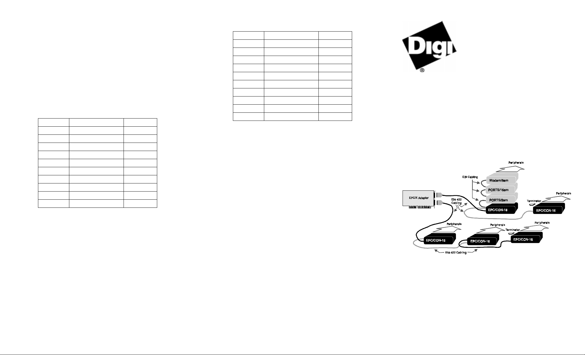
Figure 44.
Example EP C/X se tu p
This install ation guide describes how to plan your setup and install the
EPC/X host adapter and conc entrator hardware.
Page 2

Step One: Plan your setup
An EPC/X system can be set up in a variety of ways. Before you start
your installation, be sure of the following:
Number of components.
and Xem modules onto one EPC/X host adapter (using both lines). It
is a good idea to balance the number of connections on ea ch line.
Having 12 concentrators and modules on one line, and 2 on the other ,
for example, may not make the best use of line resource.
Location of components.
concentrat ors can be located up to ten feet apart. (The daisy-chain
cable that c omes wit h e ach Xem modul e a llows it to be st acked on t op
of the concentrator to which it is attached via the EBI connector.)
If your installation calls for greater distances between concentrators,
you can use twisted pair cabling in a maximum cumulative length of
up to 2000 feet (600 meters) from the host adapter.
Note: The lengt h o f t wiste d pai r c ablin g a f fects the max imum data
transfer rat e that can be expec ted over the cable. The longer
the length, the lower the rate. To maintain a baud rate of 10
Mbaud, the maximum cumulative twisted pair cable length
cannot exceed 30 feet (9 meters).
You can also us e fiber optic cable (a specia l fiber optic convers ion
option is available from Digi) that will allow a distance of up to 1.2
miles (2000 meters) from the adapter.
For even greater distances , you can attach a synchronous modem
directl y to the adapter, and remotely locate concentr ators and Xem
modules to a second synchronous modem.
Cabling.
Before beginning the installation, be s ure that you have the
cables that you wil l nee d for the distances bet ween concentrators, as
well as cables for the peripherals that you will be attaching to the concentrators and Xe m modules. EPC/X system concent r ators and
PORTS/Xem modules are available with RJ-45 or DB-25 connectors
for peripheral c abling. You will need to be sure that you have cables
of the correct length and with the right connectors to properly attach
the devices you want to us e with each concentrator or Xem module.
Power Requiremen ts.
Modem/Xem module) requ ires its own power supply. Befor e proceeding with installation, you s hould verify that adequa te line power
is avail ab l e w h ere each con ce nt r at o r (and M od e m / X em) will be
installed. Note that PORTS/Xem modules do not require power supplies when attached to an EPC/CON-16 concentr ator.
Additional information about the options available with the EPC/X
system, such as s p ecifications and ca bling details, is provided on the
CD-ROM that is packaged with the host adapter.
You can connect up to fourteen conce ntrators
Using the cables that come with the product,
Each EPC/CON-16 concentrator (and
Step Two: Install the EPC/X PCI host adapter
Before installing the EPC/X host adapte r, you shoul d do the following:
• Wear an ESD wrist strap to ground yourself while handling the
adapter. If one is not available, discharge static electricity from your
body by touching an unpainted metal surface, such as the computer’s
chassis, prior to handling the adapter.
• Record the adapter serial number, which will enabl e Digi to provide
you with better service, should the need arise.
The serial number label has this general format:
S/N: (S) XXX XXXXX
• Unplug power from the PC.
1. Remove the computer’s cover.
2. Locate an available PCI slot in your computer and remove the slot
plate.
3. Insert the adapter into the slot and screw the endplate to the computer
chassis. The endplate must be scre wed into the computer chassis to
remain in compliance with Part 15 of FCC rules.
4. Replace th e co mp u t er ’s cover.
5. Attach an EIA-422 cabl e to the co nnecto r of each li ne you will us e on
the adapter.
Step Three: Install concentrators and add-ons
1. Position concentrators and Xem modules (if any) at t he loc ation you
have prepared according to the plan you developed in
Step One
2. Attach the cable from line l on the adapter to the connector label led
HOST ADAPTER
on the fir st concentrator of the chain that is to be
connected to Line 1.
Figure 45.
Side Panel of EPC/CON-16 module
If you are cabling multiple concentrators together, attach another
cable to t he
cable to the
REMOTE
HOST ADAPTER
connector of the first concentra tor . Connect this
connector of the second concentrator.
Continue cabling until all concentrators in the chain are connected.
.
3. Install a terminator plu g in the
REMOTE
connector o f the last concen-
trator in the chain.
4. Repeat steps 2 and 3 for Line 2 on the adapter (if you are using it).
5. To cable PORTS/Xem or Modem/Xem modules to the EBI bus of a
concentrat or, atta ch one end of an EBI cable to the
tor on a concentrator and the other end to the
add-on module. Continue similarly using the
EBI IN
EBI IN
EBI OUT
connector on the
and
connec-
EBI OUT
connectors on the ad d-on mo dules until all the add-ons for a concentrator are cabled together.
6. Attach power supplies to the concentrators (and Modem/Xem mod-
ules).
7. Turn on power to the unit(s).
Step Four: Set the node numbers
Each concentrator must have a unique node number so the adapter can
recognize it on the cha in. In general , you shoul d set the node num ber of a
concentrat or ac cording to its relative position in the chain. F or example,
the concentr ator c losest to the adapte r w ould be node 1 , the s econd would
be node 2, and so on. To set the node number, do the following:
P1
1. Wait until you see
30 seconds after you power on the unit). This indicates that the
Power-on Self Test has successfully com pleted.
2. Press the right arrow button once to display the current node number.
1n
is the default.)
(
3. Press the left arrow button to increment the node number. Node num-
bers go up to
8n
4. To save the node number currently displaye d on the front panel, pr es s
the ri gh t arrow but to n onc e. If the number was succes sfully saved to
EEPROM, the display will read
displayed on the front panel of the unit (about
and then return to 1n.
Pn
.
 Loading...