

Page 1
90033900 B
EIA-422 Mode (E th er Li te 2 or 16 2 onl y)
To operate a port of the EtherLite 162 EIA-422 in EIA-422 mode, set the
port’s EIA-422 ENABLED switch to the up po sition. Set the TERMINATION (422 ONLY) switch to the down position. This switch connects a
120 ohm, 1/2 watt resistor across the in put signals.
EtherLite 2 EIA-422 ports are hard-wired to EIA-422 mode, and have no
termination installed. Pinouts are shown in the table below.
Note:
2-wire multidrop configurat ion for EIA-422 is not supported.
EIA-422 Pinouts
*EIA-232 signals on EtherLite EIA-422 only
EIA-485 Mode (EtherLite 2 EIA-485 only)
EtherLite 2 EIA-485 ports are wired for half dupl ex multiple drop EIA485 mode and have no termination insta lled.
EIA-485 Pinouts
Environmental Specifications
Operating Temperature
32°F (0°C) to 122°F (50°C) for units with less than 32 ports
32°F (0°C) to 95°F (35°C) for 32-port units
Storage Temperature
-13°F (-25°C) to 167°F (75°C)
Operating or Storage Humidity
0 to 90% non-condensing
A.C Power Requirements (maximum)
100-240 VAC, 50-60 Hz
15W (15VA) for units with less than 32 ports
25W (25VA) for 32-port units
CAUTION:
To prevent electric shock, do not remove the
cover of an EtherLite module. There are no user-serviceable
parts inside. Refer servicing to qualified personnel.
Copyright
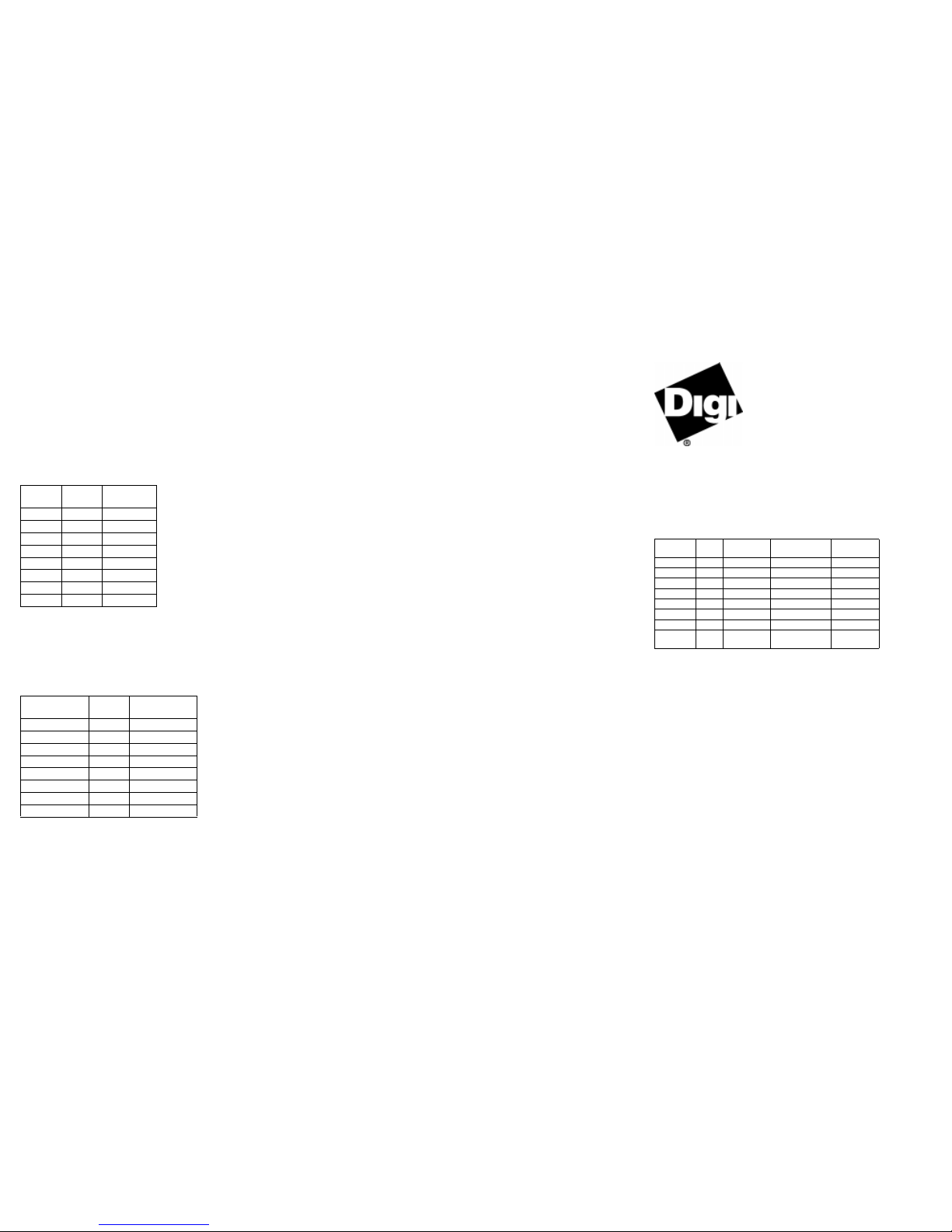
The Digi logo a nd EtherLite ar e registered trademarks of Digi International. All other brand and product
names are trademarks of their respective holders.
© Digi Inter nat io nal Inc., 19 99
All Rights Reserved
Information in this document is subject to change without notice and does not represent a commitment on
the part of Digi International.
Digi provides this document “as is”, without warranty of any kind, either expressed or implied, including, but not limited to, the implied warranties of fitness or merchantability for a particular purpose. Digi
may make improve ments and/or c ha nges in this manual or in the prod uc t(s) and/or the program(s)
described in this manual at any time.
This product could include technical inaccuracies or typographical errors. Changes are periodically made
to the information herein; these changes may be incorporated in new editions of the publication.
EtherLite
Hardware
Information Guide
Overview
Digi EtherLite serial port serve r s connect asynchronous serial ports to
10BASE-T and 100BASE-T Ethernet connections. Most EtherLite servers support speeds up to 115Kbps or 230Kpbs on all ports simultaneously. This table shows all EtherLite models and their capabilities.
EtherLite Models
* Individual ports are configurable as either EIA-232 or EIA-422.
** 115Kbps is not att ainable on all ports simultaneousl y on the EL-32.
Installing the EtherLite Software
Install the hardware before y ou install the device driver softwa re. Follow
the software installation instructions included on the Acce ss Resource
CD.
Ethernet Cabling Requirements
The EtherLite unit requires an unshielded twisted-pair (UTP) 10Bas e-T
Ethernet or 100Base-T X connec tion. In orde r to maintai n radi o fre quency
emissions compliance, use EIA/TIA 568-compliant Category 4 or Category 5 for 10Base-T and Category 5 only for 100Base-TX.
Installing the EtherLite Hardware
1. Write the Ethe rnet addr ess of the uni t on the fol lowi ng line . It will be
needed during software instal lation. This address is printed on a
label attached to the unit.
Signal
RJ-45
Pin
Direction
RTS* 1
RxD(-) 2 input(-)
DCD* 3
RxD(+) 4 input(+)
TxD(+) 5 output(+)
SG 6
TxD(-) 7 output(-)
CTS* 8
Signal
RJ-45
Pin
Direction
No connect 1
No connect 2
No connect 3
TX(A)/RX(A) 4 Bidirectional
TX(B)/RX(B) 5 Bidirectional
GND 6
No connect* 7
No connect* 8
*Do not connect any signal.
Model
Serial
Ports
Port
Protocol
Ethernet
Connection
Maximum
Baud Rate
EL 2 2 EIA-232 10BASE-T 230Kbps
EL 2 2 EIA-422 10BASE-T 230Kbps
EL 2 2 EIA-485 10BASET 230Kbps
EL 8 8 EIA-232 10BASE-T 115Kbps
EL 16 16 EIA-232 10BASE-T 115Kbps
EL 32 32 EIA-232 10BASE-T 115Kbps**
EL 160 16 EIA-232 10/100BASE-T 230Kbps
EL 162 16
EIA-232 or
EIA-422*
10/100BASE-T 115Kbps
Page 2
Ethernet Address #_____________________________________
2. Connect the Ethernet cable to the unit using the RJ-45 jack la beled
10BASE-T or 10/100BASE-T located on the front of the cabinet.
Use the provided straight-through cable to connect the unit to a hub.
Connecting directly to an Ethernet card will require a 10Base-T
crossover cable (not provided). Note that either wiring scheme
requires that the twisted pa irs be use d for spec ific pai rs of pins: 1& 2,
3&6, 4&5, and 7&8.
RJ-45 Pinouts
3. Connect the power supply to your unit a nd an AC outlet. If your unit
has an internal power supply, connect the power cord to the unit and
an AC outlet.
4. Power up the unit. The power LED on the front of the cabinet will
flicker while awaiting BOOTP or DHCP service from a host. (It will
remain flickering until the unit has been served an IP address by
either a bootp or DHCP server.) After an IP address has been
received, th is LED will remain steadily lit. Verify that the Link LED
is on. If the Link LED is not on and the ON LED is still flickering,
verify that you are using the correct cable type. Also verify that the
hub and Ethernet host are powered. If the ON LED is flashing
slowly, notify Digi Technical Support.
5. If the unit do es not operate properly, verify that it has p ower and that
both LEDs are on.
Rack Mount Installation
For the EtherLite 32, a rack mount kit is included. The rac k mount brackets may be installed at either the front or rear of the unit.
To install each bracket, do the following:
1. Remove the two screws on the side of the cabin et.
CAUTION: Do not remove the top cover as AC power is then
accessible!
2. Align the countersunk holes of the bracket with the vacated holes in
the cabinet. Use the countersink screws to fasten the bracket to the
cabinet.
Rack Mount Considerations
When doing a rack mount installation consider the following:
• Cumulative power requirements of the unit and other equipment
installed in the rack. Do not overload rack supply circuits.
• Safety and stability. Always st ack the rack from bottom up t o ens ure
a stable and safe rack. Note the EtherLite 32 weighs 3.2 lbs.
• Air flow in the rack. Make sure the unit’s ambient temperature does
not exceed 95°F (35°C).
• Grounding. Earth ground the unit r eliably to the rack system. The
earth ground connection must be maintained when the supply connection is ot h er than a direct connection to the br an ch circuit.
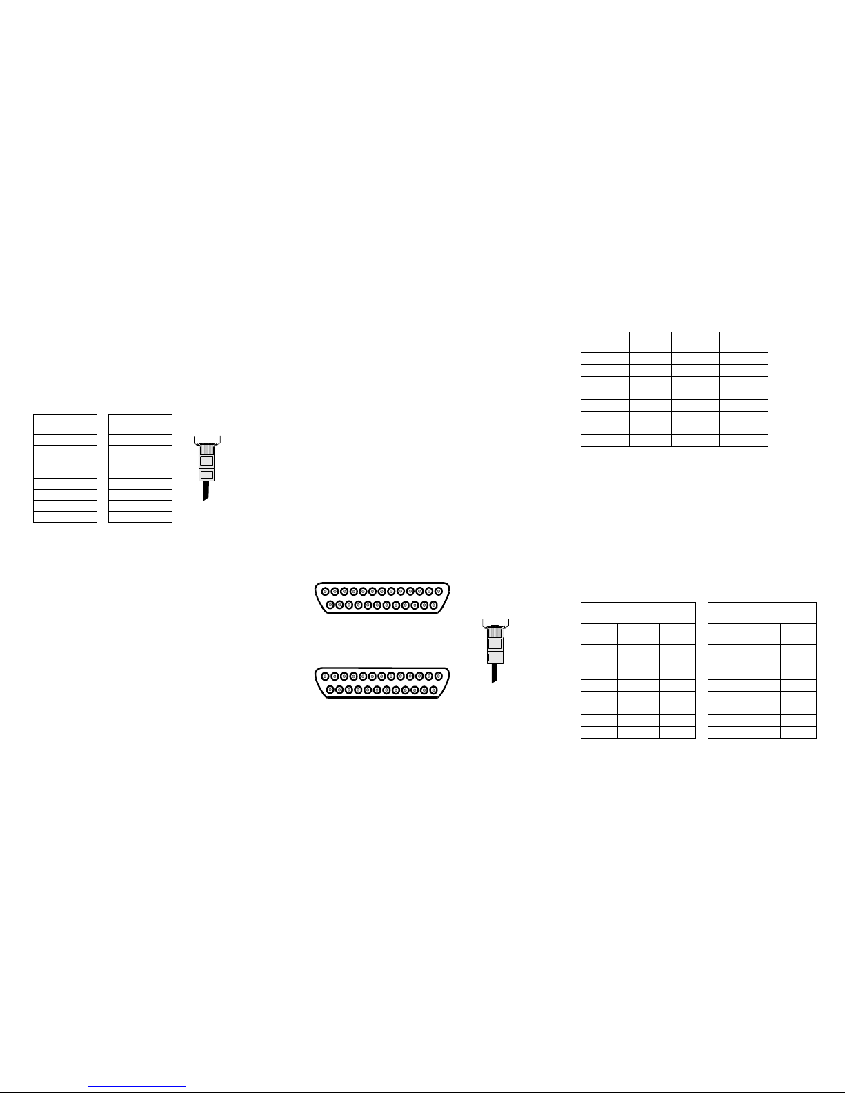
EIA - 232 Connectors
Many EIA-232 serial devices imple me nt their serial ports with DB-25
connectors. The EtherLite uni ts have seria l port s implement ed with 8-pin
RJ-45 modular jacks, with each signal us ing EIA-232 volt ag e levels. The
figures below shows the pinouts of all these connector types.
EIA-232 DTE Pinouts
IMPORTANT: RJ-45 c ables designed for other Digi products must not
be used with Digi EtherLite and SCSI Terminal Server prod ucts. The
EtherLite RJ-45 pin configuration differs from the configuration of the
RJ-45 connectors used on ot her Digi p roduc ts. The ta ble abo ve shows th e
different signa ls, along with the standard DB-25, DB-9 and th e E therLite
8-pin RJ-45 pinout.
The most convenient method of mating DB-25 a nd DB-9 serial devices
to your ELPS is to use RJ-45 to DB-25 and RJ -45 to DB-9 adapters. This
allows the DTE/DCE selection to occur at the adapte r, while using
“straight-through” modular cables. To assure CE mark compliance
(Europe), all serial cables must be shielded. The following RJ-45 to DB25 adapters are available from Digi International, along with two-me ter
unshielded straight-through modular cables (SA-0024):
RJ-45 to DB-25 Adapters
Straight-through Crossover
PintoPin PintoPin
1to1 1to3
2to2 2to6
3to3 3to1
4to4 4to2
5to5 5to4
6to6 6to5
7to7 7to7
8to8 8to8
Pin 1 Pin x
RJ-45 Plu
g
13
1
14
25
Male DB-25
13
1
14
25
Female DB-25
Pin 1
Pin x
RJ-45 Plug
EtherLite
RJ-45 Pin
Si
g
nal DB-25 Pin DB-9 Pin
1RTS (out)4 7
2DSR (in) 6 6
3DCD (in) 8 1
4RxD (in) 3 2
5 TxD (out) 2 3
6GND 7 5
7DTR (out)20 4
8CTS (in) 5 8
P/N 76000450
(DTE to Modems)
P/N 76000451
(DCE to Terminals/Printers)
RJ-45
Jack
Si
g
nal
DB-25
Male
RJ-45
Jack
Signal
DB-25
Male
1RTS4 1RTS5
2DSR6 2DSR6
3 DCD 8 3 DCD 20
4RxD3 4RxD3
5TxD2 5TxD2
6GND7 6GND7
7 DTR 20 7 DTR 8
8CTS 5 8CTS 4
 Loading...