

Page 1
91001071_B
Pin Assignments
DB-25 and DB-9 Pin Assignments
RJ-45 Pin Assignments for 10-Pin and 8-Pin RJ-45
Connectors
Refer to the Digi CD for more detailed cabling information or visit
http://support.digi.com for more information.
Digi, the Digi Connectware logo, Ac celePort, and Digi Neo are trademarks or regist ered
trademarks of Digi International in the Unite d States and other countries. All other brand
and product names are trademarks of their respective hol ders.
© Digi International Inc., 2001, 2002, 2003 All Rights Reserved; www.digi.com
Information in this document is subject to change without notice and does not represent a
commitment on the part of Digi International.
Digi provides this document “as is,” withou t warranty of any kind, either expressed or
implied, including, but not limited to, the implied w arr anties of fitness or merchantability
for a particular purpose. Digi may make improvements and/or changes in this manual or in
the product(s) and/or the program(s) described in this manual at any time.
This product could in clude technical inaccuracies or typographical errors. Changes ar e periodically made to the information herein; these changes may be incorporated in new editions
of the publication.
Digi Neo
PCI Host Adapters
EIA-232
Hardware Installation
Guide
Introduction
A Digi Neo™ adapter easily expands the number of EIA-232 ports
available on your computer, allowing you to cable additional peripheral
devices, such as modems, terminals or serial printers, directly to your
computer.
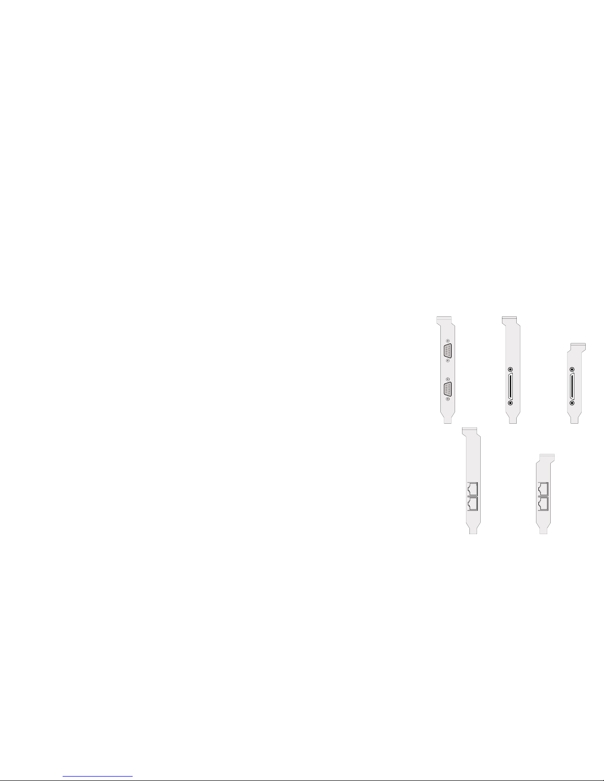
The Digi Neo 2 port adapter has two connectors (DB-9 or RJ-45) on the
adapter to provide peripheral port connections.
Digi Neo 4 and 8 port adapters are equipped with an HD-68 connector to
which a special Digi connector assembly is attached to provide the
peripheral port connections. There are seven different connector assembly options available to use with Digi Neo 4 and Neo 8 adapters:
• RJ-45 Connector Box
• DB-25 Connector Box (male connectors)
• DB-9 Connector Box (male connectors)
• DB-25 Fan-out Cable (male or female connectors)
• DB-9 Fan-out Cable (male or female connectors)
This installation guide describes how to plan yo ur setup and install a Digi
Neo adapter.
Signal Description DB-25 Pin DB-9 Pin
GND Chassis Ground Shell Shell
TxD Transmitted Data 2 3
RxD Received Data 3 2
RTS Request To Send 4 7
CTS Clear To Send 5 8
DSR Data Set Ready 6 6
SG Signal Ground 7 5
DCD Data Carrier Detect 8 1
DTR Data Terminal Ready 20 4
RI Ring Indicator 22 9
Signal Description Pin # (of 10) Pin # (of 8)
RI Ring Indicator
1N/A
DSR Data Set Ready
2† 1†
RTS Request To Send
32
GND Chassis Ground
43
TxD Transmitted Data
54
RxD Received Data
65
SG Signal Ground
76
CTS Clear To Send
87
DTR Data Terminal Ready
98
DCD Data Carrier Detect
10 N/A
† DSR (Pin 2 on a 10 pin conn ector, Pin 1 on an 8 pin conne ctor)
can be swapped with DCD by using the ALTPIN configuration
option. ALTPIN reverses the position of these two signals in 10
pin connectors and allows DCD to be used instead of DSR on an
8 pin connector.
Consult the driver documentation for how to do this in your
specific operating system.
Page 2
Step One: Plan Your Setup
A Digi Neo adapter can be set up in a variety of ways. Before you start
your installation, consider the following:
Number of Components. You can connect two peripheral de vices to a Digi
Neo 2, up to four peripheral devices to a Di gi Neo 4, and eigh t perip heral devices to a Digi Neo 8 adapter. Up to four Digi Neo adapters
may be installed in a computer.
Construction of Cables. To achieve the greatest reliability over distance,
cables should be:
• Shielded, low capacitance, and preferably designed specifically
for serial data transmission.
• Grounded at both ends of the cable.
• Routed away from noise sources such as generators, motors and
fluorescent lights.
Cable Connections. Before beginning the i nstallat ion, verify that you have
the appropriate Digi connector assemblies (fan-out cables or connector box assemblies). Fan-out cable and connector box options are
described in detail in a separate Cable Usage Guide.
You will also need a cable for each peripheral that you will be attaching to the connector assembly. The connector type that you need at
either end of the peripheral cable depends on the type of Digi conn ector assembly that you use and the connector on the peripheral.
Digi connector assemblies are available with RJ-45, DB-25 or DB-9
connectors. You will need to be sure that you have cables of the correct length and with the right connectors to properly attach the
devices you want to use.
Additional information about the Digi Neo adapter , such as specifications
and cabling details, is provided on the Digi CD which is packaged with
the adapter.
Step Two: Install the Neo Adapter
CAUTION! To guard against damage to the adapter due to electrostatic
discharge (ESD), do not remove the adapter from its protective packaging until you have grounded yourself to the computer chassis (see step 4,
below).
1. Shut down your computer in the manner recommended for you r oper-
ating system.
2. Unplug power from the computer.
3. Remove the computer’s cover.
4. Touch the computer chassis to equalize any static potential between
yourself and the computer. This will help prevent damage to the
adapter due to electrostatic discharge.
5. Locate an available PCI slot in your computer and remove the slot
plate.
6. Remove the adapter from its protective packaging.
7. Write down the serial number of the adapter in the space provided
below.
8. Insert the adapter into the slot and screw the endplate to the com puter
chassis. The endplate must be screwed into the computer chassis to
remain in compliance with Part 15 of FCC rules.
9. Replace the computer’s cover.
10.Attach the peripheral interconnect cable(s) to the adapter.
CAUTION: Many SCSI adapters use the same HD-68 connector type as
the Neo adapter. Do not plug SCSI devices into the Digi connector, and
do not plug Digi peripheral cables into SCSI adapters.
Serial Number: ________________________
Step Three: Install Peripheral Cabling
You can co nnect modems, t erminals, se rial printers , or any other s tandard
EIA-232 device to a Digi Neo adapter using a cable between the peripheral and the Digi connector assembly.
On the peripheral end of the cable, the connector you must have depends
on the requirements of the peripheral. The Digi end of the cable must be
equipped with the connector type that mates with the connectors on the
Digi connector assembly
In the case of the 2 port product, the cables are connected directly to the
adapter’s end-plate.
Port 1
Port 2
Ports
1-4
1-8
Low
Profile
Port 1
Port 2
Port 1
Port 2
2p
4p
8p
4p / 8p
2p
2p
RJ-45
RJ-45
Low
Profile
Ports
1-4
1-8
 Loading...