

Digi Edgeport/1i, Edgeport/2i, Edgeport/4s MEI, Edgeport/2s MEI, Edgeport/4s DC Isolated Installation Manual
...
Edgeport®
USB Expansion Modules-Industrial
Installation Guide

Revision history—90000409
Revision Date Description
G March, 2009 No changes to the document.
H April, 2009 Added RoHS compliance information for China.
J June, 2009 Updated the product CD.
K December, 2017 Updated branding and made editorial enhancements.
Trademarks and copyright
Digi, Digi International, and the Digi logo are trademarks or registered trademarks in the United
States and other countries worldwide. All other trademarks mentioned in this document are the
property of their respective owners.
© 2017 Digi International Inc. All rights reserved.
Disclaimers
Information in this document is subject to change without notice and does not represent a
commitment on the part of Digi International. Digi provides this document “as is,” without warranty of
any kind, expressed or implied, including, but not limited to, the implied warranties of fitness or
merchantability for a particular purpose. Digi may make improvements and/or changes in this manual
or in the product(s) and/or the program(s) described in this manual at any time.
Warranty
To view product warranty information, go to the following website:
www.digi.com/howtobuy/terms
Send comments
Documentation feedback: To provide feedback on this document, send your comments to
techcomm@digi.com.
Customer support
Digi Technical Support: Digi offers multiple technical support plans and service packages to help our
customers get the most out of their Digi product. For information on Technical Support plans and
pricing, contact us at +1 952.912.3444 or visit us at www.digi.com/support.
Edgeport Industrial Installation Guide
2

Contents
USB Expansion Modules-Industrial
Edgeport/1i
Cabling Edgeport 6
USB connection 6
RS-422/485 serial connection 6
Jumper wire based mode configuration 7
Edgeport/2i
Cabling Edgeport 8
USB connection 8
RS-422/RS-485 serial connection 8
Cable connections (DB9 female) for full duplex 8
Cable connections (DB9 female) for half duplex 9
Configuring the DIP switches 9
Two-position switch 9
Eight-position switch 9
Edgeport/2s MEI, Edgeport/4s MEI, Edgeport/4s Isolated, Edgeport/8s
MEI
Cabling Edgeport 11
USB connection 11
Cable connections (DB9 female) for full duplex 11
Cable connections (DB9 Female) for half duplex 12
DB9 RS-232 pin assignment 12
Configuring the port flags 13
Edgeport mounting diagrams
For all Edgeports except the Edgeport/1i 14
Edgeport Industrial Installation Guide
3

Edgeport driver installation
Edgeport configuration utility
General tab 16
Information tab 17
Configuration tab 18
Port Flag Configuration tab 19
Confidence Test tab 22
Power Management tab 23
Port Status tab 24
Version tab 25
Advanced tab 26
Edgeport system status light
For all Edgeports except the Edgeport/1i 28
Understanding hubs
Regulatory information
Edgeport Industrial Installation Guide
4

USB Expansion Modules-Industrial
This manual covers the following models:
n Edgeport/1i
n Edgeport/2i
n Edgeport/2s MEI
n Edgeport/4s MEI
n Edgeport/4s DC Isolated
n Edgeport/8s MEI
Edgeport Industrial Installation Guide
5

Edgeport/1i
Edgeport® USB-to-Serial Converters from Digi International provide high-speed serial connectivity via
USB port expansion for Windows-based applications. Edgeport/1i provides one RS-422/485 serial DB-9
port. For more detailed information, as well as the latest manual and technical updates, visit
www.digi.com/support/Edgeport.
Cabling Edgeport
USB connection
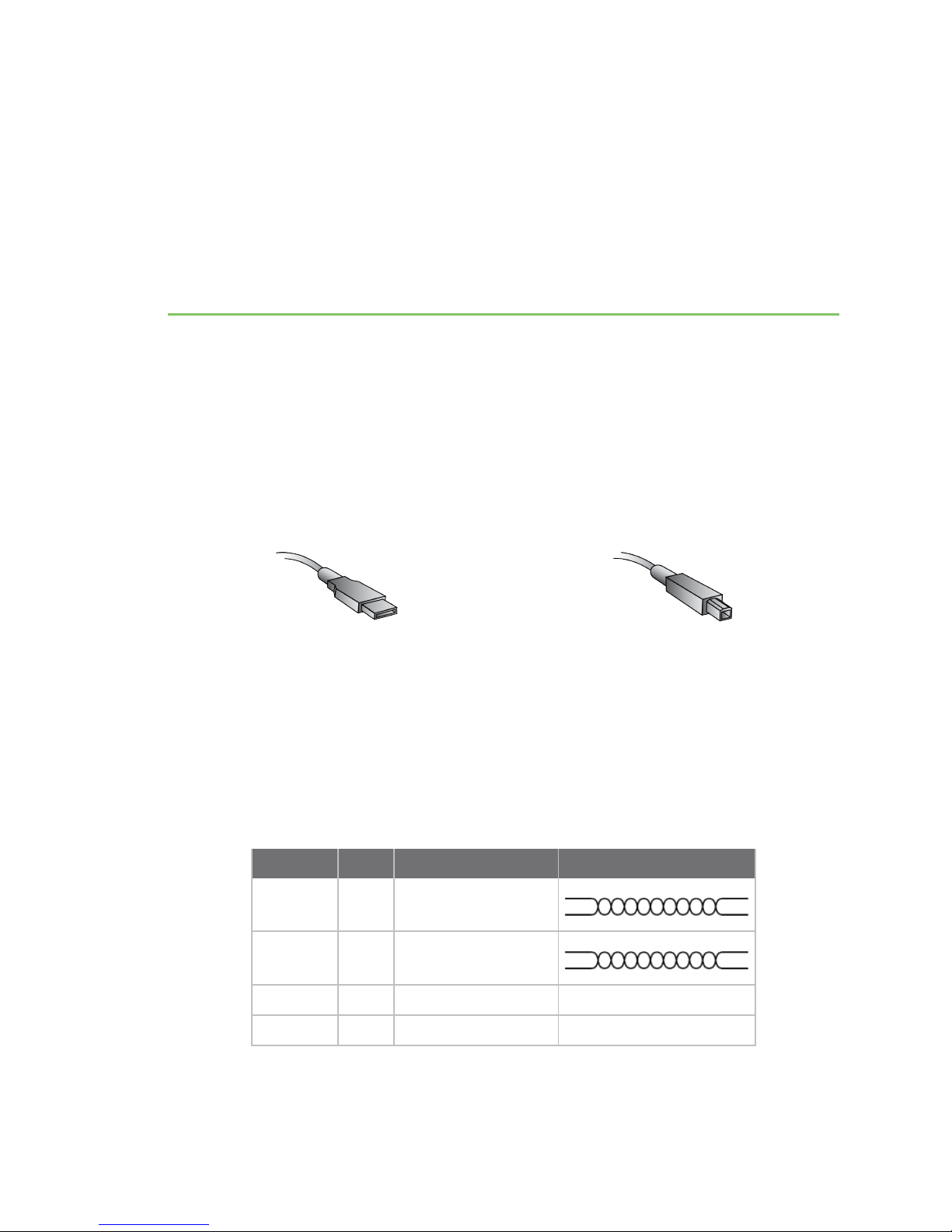
Type A
Plug the Type A (flat) end of the USB cable into the USB port located in the back of your PC or into an
available USB port on a standard hub or into a Digi International Hubport. Plug the Type B (square)
end of the USB cable into the Edgeport.
RS-422/485 serial connection
The Edgeport/1i supports RS-422/RS-485 protocol. To configure the features of RS-422/485
communication on the Edgeport/1i, you will short or leave certain pins unconnected at the DB9
connector of the cable. See the following pin assignment tables:
Cable connections (DB9 female) for full duplex
Pin Signal Description
3 ▶ TA
7 ▶ TB
8 ▶ RA
4 ▶ RB
(T-)
(T+)
(R-)
(R+)
transmit data negative
transmit data positive
receive data negative
receive data positive
Type B
Edgeport Industrial Installation Guide
6

Edgeport/1i Jumper wire based mode configuration
Pin Signal Description
5 ▶ signal ground
2 ▶ no connect
Cable connections (DB9 female) for half duplex
Pin Signal Description
3 ▶ TA
7 ▶ TB
8 ▶ RA
4 ▶ RB
5 ▶
1 ▶
2 no connect
Note Short pin 1 to pin 5 (GND).
(T-)
(T+)
(R-)
(R+)
transmit data negative
transmit data positive
receive data negative
receive data positive
signal ground
full and half duplex
Jumper wire based mode configuration
For "jumper wire" based mode configuration, use the following pins:
Pin Description
1 ▶ full and half duplex
6 ▶ echo on and off
The user can switch on and off the following features:
n Line termination (120 ohm): To enable the line termination resistor, connect pin 9 to pin 8. To
disable line termination, leave pin 9 unconnected.
n Full Duplex and Half Duplex: For Full Duplex operation, leave pin 1 unconnected. For Half
Duplex operation, short pin 1 to pin 5 (GND) at the cable connector.
n Echo On and Echo Off: For Echo On mode, leave pin 6 unconnected. For Echo Off mode, short
pin 6 to pin 5 (GND) at the cable connector.
If the drivers are not already installed, see Edgeport driver installation.
Edgeport Industrial Installation Guide
9 ▶ line termination
7
Edgeport/2i
Edgeport USB-to-Serial Converters from Digi International provide high-speed serial connectivity via
USB port expansion for Windows-based applications. Edgeport/2i provides a combination of up to two
RS-422 and/or RS-485 serial DB-9 ports. For more detailed information, as well as the latest manual
and technical updates, visit www.digi.com/support/Edgeport.
Cabling Edgeport
USB connection
Type A
Plug the Type A (flat) end of the USB cable into the USB port located in the back of your PC or into an
available USB port on a standard hub or into a Digi International Hubport. Plug the Type B (square)
end of the USB cable into the Edgeport.
RS-422/RS-485 serial connection
Cable connections (DB9 female) for full duplex
Pin Signal Description
3 ▶ TA
7 ▶ TB
8 ▶ RA
4 ▶ RB
5 ▶ signal ground
1, 2, 6, 9 no connect
(T-)
(T+)
(R-)
(R+)
transmit data negative
transmit data positive
receive data negative
receive data positive
Type B
Edgeport Industrial Installation Guide
8

Edgeport/2i Configuring the DIP switches
Note For full duplex (in the above diagram) the differential pair TA and TB should be together in one
twisted pair and RA and RB should be together in another twisted pair.
Cable connections (DB9 female) for half duplex
Pin Signal Description
3 ▶ TA
7 ▶ TB
8 ▶ RA
4 ▶ RB
5 ▶ signal ground
1, 2, 6,
9
Note Half duplex contains only one twisted pair.
(T-)
(T+)
(R-)
(R+)
transmit data negative
transmit data positive
receive data negative
receive data positive
no connect
Configuring the DIP switches
Two-position switch
The two-position DIP switch, located on the back panel, connects the signal ground to chassis ground.
IMPORTANT: Do not connect signal ground to chassis ground on more than one location in order to
prevent ground loops and potentially high currents.
Eight-position switch
The Edgeport/2i also has two sets of eight position DIP switches, located on the back panel next to
their corresponding serial port.
The following figure shows what each switch selects in the ON and OFF positions.
Edgeport Industrial Installation Guide
9

Edgeport/2i Configuring the DIP switches
Consult the diagrams in the following figure for various configuration options.
If the drivers are not already installed, see Edgeport driver installation.
Edgeport Industrial Installation Guide
10
 Loading...