

Page 1

SERVICE MANUAL
Model: DS-685L/F Series
Edition Month Year
1st March 1996
2nd May 1996
3rd April 1997
4th March 2002
5th
SHANGHAI TERAOKA ELECTRONIC CO., LTD. --- Technical Service Dept.
Ting Lin Industrial Development Zone, Jin Shan District, Shanghai P. R. China 201505
Tel: +86-21-5723-4888 Fax: +86-21-5723-9330 E-Mail:
steservice@digi-scale.com
Page 2

DS-685L/F Service Manual Revised
CONTENT
1. General Specification
1.1. Model Specification --------------------------------------------------------------------- 1
1.2. Features ----------------------------------------------------------------------------------- 1
1.3. Overall View ------------------------------------------------------------------------------ 2
1.4. Dimension --------------------------------------------------------------------------------- 3
1.5. Key-Sheet Layout ----------------------------------------------------------------------- 4
1.6. Key Function ----------------------------------------------------------------------------- 4
1.6.1. Type A (8 Preset Keys) ---------------------------------------------------------- 4
1.6.2. Type B (14 Preset Keys) -------------------------------------------------------- 4
1.7. Operation Condition -------------------------------------------------------------------- 5
1.8. Charging Condition (For Rechargeable Battery Only) ------------------------- 5
1.9. Analog Specification ------------------------------------------------------------------- 5
1.10. Main Components Used ------------------------------------------------------------- 5
1.11. Capacity / Minimum Graduation / Tare Range --------------------------------- 6
1.11.1. DS-685L --------------------------------------------------------------------------- 6
1.11.2. DS-685F --------------------------------------------------------------------------- 6
2. Maintenance Mode
2.1. SPAN SW Location & Stopper Screws ------------------------------------------- 7
2.2. Internal Count & A/D Count Display ----------------------------------------------- 7
2.3. SPAN Adjustment ---------------------------------------------------------------------- 8
2.4. Escape From Calibration Mode ----------------------------------------------------- 8
2.5. Specification Setting Operation ----------------------------------------------------- 9
2.5.1. User Specification Setting (141) ----------------------------------------------- 9
2.5.2. Specification Entry (142) -------------------------------------------------------- 9
2.6. DS-685L Specification List (V1.26) ------------------------------------------------ 10
2.6.1. Customer Specification List (141) V1.26 ------------------------------------ 10
2.6.2. Weight & Measure Specification List (142) V1.26 ------------------------- 10
2.7. DS-685F Specification List (V1.06) ------------------------------------------------- 12
2.7.1. User Specification List (141) V1.06 ------------------------------------------- 12
2.7.2. For Weight & Measure (142) V1.06 ------------------------------------------- 12
2.8. Location of Sealing Screw ------------------------------------------------------------ 14
3. Error Message ------------------------------------------------------------------------------- 15
4. Hardware Detail
4.1. DS-685L ----------------------------------------------------------------------------------- 16
4.1.1. NRFI Electrical Connection Block Diagram --------------------------------- 16
1
Page 3

DS-685L/F Service Manual Revised
4.1.2. RFI Electrical Connection Block Diagram ----------------------------------- 16
4.1.3. Microcomputer Pin Assignment ------------------------------------------------ 17
4.2. DS-685F ----------------------------------------------------------------------------------- 19
4.2.1. NRFI Electrical Connection Block Diagram --------------------------------- 19
4.2.2. RFI Electrical Connection Block Diagram ----------------------------------- 19
4.2.3. Microcomputer Pin Assignment ------------------------------------------------ 20
5. Circuitry Diagram ---------------------------------------------------------------------------- 22
2
Page 4

CONTENT
I. INTRODUCTION
1. Feature ........................................................................................................ I-1
II. SPECIFICATION
1. General specification
1.1 Overall view ................................................................................. II-1
1.2 Dimension ................................................................................. II-2
1.3 Model specification ..................................................................... II-3
1.4 Operation condition ……………………………………………… II-3
1.5 Main components used ……………………………………………… II-3
1.6 Capacity / Minimum graduation / Tare range ……………………… II-4
III. INITIAL SETUP
1. Specification setting
1.1 Specification entry (141) ..................................................................... III-1
1.2 Specification entry (142) ..................................................................... III-2
1.3 Specification list of DS-685 (Version 1.21) ……................................... III-3
1.4 Specification list of DS-685F (Version 1.00) …………………………..
III-6
2. Key layout and function
2.1 8 preset key type ..................................................................... III-9
3. Location of sealing screw ................................................................................. III-11
4. Set up procedure ………................................................................................. III-11
IV. ADJUSTMENTS
1. Span enable switch setting ................................................................................. IV-1
2. Internal count and A/D count ...................................................................... IV-1
3. Span adjustment ............................................................................................. IV-1
4. Escape from maintenance mode ...................................................................... IV-2
5. Error message ............................................................................................. IV-3
V. ELECTRICAL CIRCUITRY
1. DS-685
2. DS-685F
Page 5

DS-685L/F Series Service Manual
Page No. 1
1. General Specification
1.1. Model specification
z Model Name: DS-685L / DS-685F
z Display Resolution: 1/3,000
z Internal Resolution: 1/30,000 (DS-685)
1/60,000 (DS-685F)
z Platter Size: 300mm x 225mm (11.8” x 8.8”)
z Display: Double-sided display
A) LCD display version
Weight - 5 digits
Unit Price - 5 digits / - 6 digits (1 fixed zero) / - 7 digits (2 fixed zeros)
Total Price - 6 digits / - 7 digits (1 fixed zero) / - 8 digits (2 fixed zeros)
B) FIP display version
Weight display - 5 digits
Unit price display - 5 digits
Total price display - 6 digits
1.2. Features
DS-685 offers the following features:
z Low cost digital price computing scale
z Quick response to weight changes
z Capacity: 3kg, 6kg, 15kg, 30kg, 30lb
z Resolution:
A) DS-685 (LCD display): Display resolution 1/3,000, Internal resolution 1/30,000.
B) DS-685F (FIP display): Display resolution 1/3000, Internal resolution 1/60,000.
z Low power consumption:
A) DS-685 (LCD display): 6 x D size dry battery back up for more than 500 hours of
continuous usage.
B) DS-685F (FIP display): Rechargeable battery backup for 8 hours of continuous
usage. (Optional)
z Battery low detection
A) DS-685L (LCD Display)
Two –Point lower detect for Dry Battery
* When battery is weak, the battery indicator will light up.
* When the power from battery becomes lower, scale cannot compute accurately,
all display will shut off except the battery indicator. The power is then shut off
completely after 1 minute.
Page 6

DS-685L/F Series Service Manual
Page No. 2
B) DS-685F (FIP Display)
Four-Point battery status detect (Rechargeable battery)
* When battery is weak, the battery indicator will light up.
* When the power from battery becomes lower, scale cannot compute accurately,
all displays will shut off except the battery indicator. The power is then shut off
completely after 1 minute.
* When battery needs to charge and AC power available, battery will be charged.
* Automatically stop charging when battery is fully charged.
z Calibration by software
z Splash water proof
z Customer and operator displays (optional customer pole display)
z 30 keys: ON/OFF key, 10 Numeric keys, 11/5 Operational keys, 8/14 Preset keys
z Plastic housing
z Display Tube:
DS-685L: High contrast LCD display
DS-685F: FIP display
1.3. Overall view
DS-685 Bench type DS-685 Pole type
Page 7
DS-685L/F Series Service Manual
Page No. 3
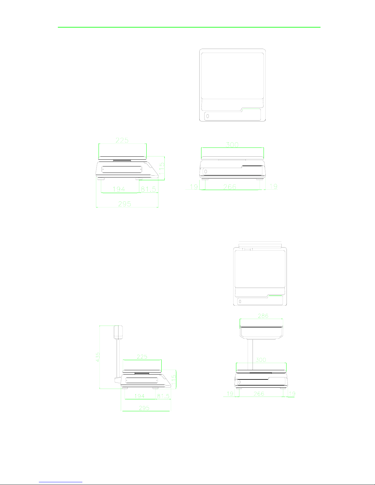
1.4. Dimension
DS-685 Bench type
DS-685 Pole type
Page 8
DS-685L/F Series Service Manual
Page No. 4
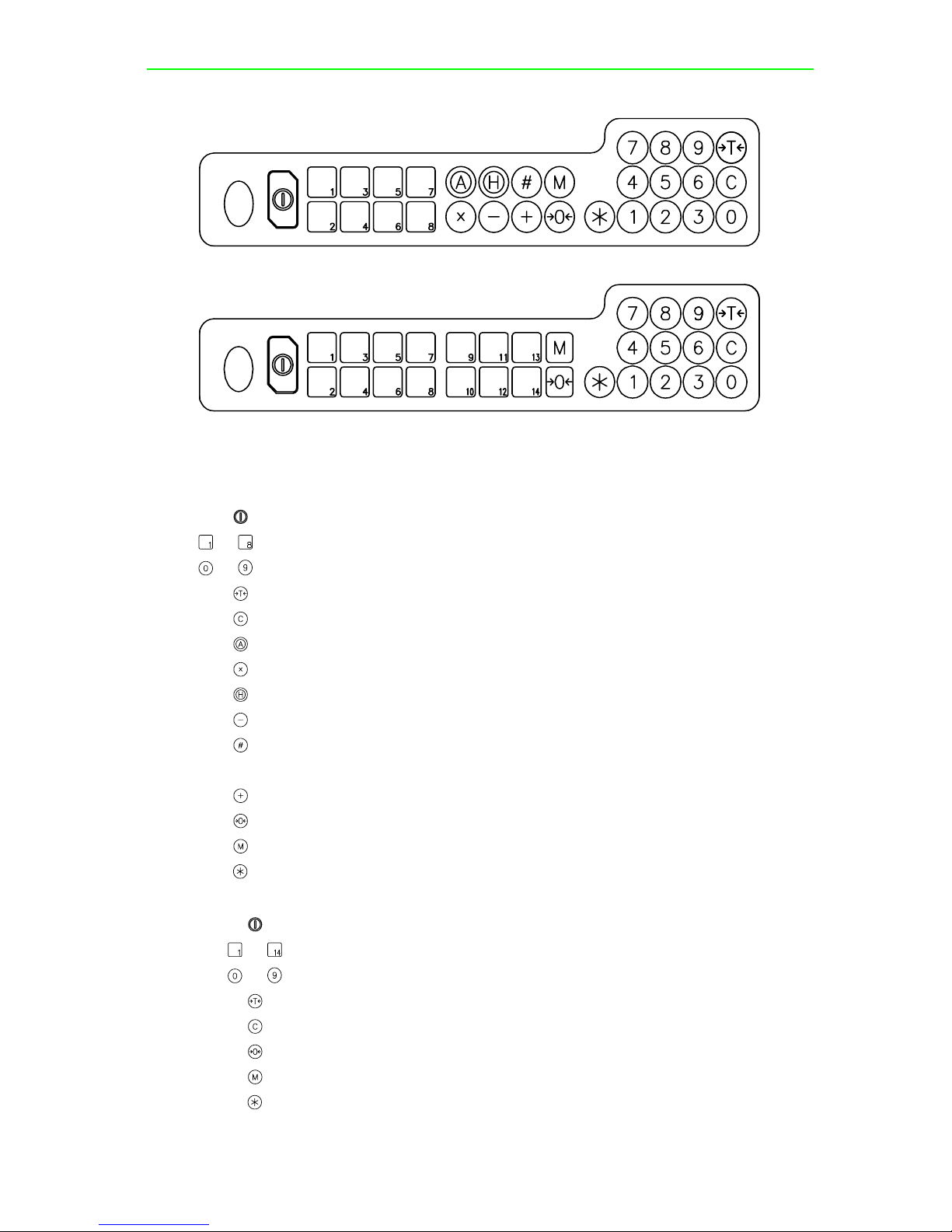
1.5. Key-Sheet Layout
Keysheet Type A
Keysheet Type B
1.6. Key Function
1.6.1. Type A (8 Preset Keys)
: ON/OFF key. Turn the power ON or OFF.
to
: PRESET keys. Set up or call either unit price.
to
: Numeric keys. Input numeric value.
: TARE key. Set or clear tare value.
: CLEAR key. Clear numerical values.
: AUTO key. Select whether or not to clear a unit price (and/or) tare value.
: Multiple key, Register the same non-weighing product multiple times.
: HOLD key. Holds the display value for 8 seconds.
: MINUS key. Correction operation on products.
: AMT/TEND key. Used to enter amount tendered. Two different types of AMT/TEND
operation can be selected by SPEC 9 BIT 3.
: PLUS key. Adds sum, accumulated sum.
: RE-ZERO key. Resets weight display to zero.
: MODE SET key. Switch into following modes: Program & Grand Total Check Mode.
: Data Setting key. Set up or clear mode.
1.6.2. Type B (14 Preset Keys)
: ON/OFF key. Turn the power ON or OFF.
to
: PRESET keys. Set up or call either unit price.
to
: Numeric keys. Input numerical value.
: TARE key. Set or clear tare value.
: CLEAR key. Clear numerical values.
: RE-ZERO key. Resets weight display to zero.
: MODE SET key. Switch into Program Mode.
: Data Setting key. Set up or clear mode.
Page 9

DS-685L/F Series Service Manual
Page No. 5
1.7. Operation Condition
z Power source
a) DS-685L: AC 240/230/220V, 117/100V (+10%, -15%) (Factory Set)
DC 6 x D size dry battery (9V)
b) DS-685F: AC 240/230/220V, 117/100V (+10%, -15%) (Factory Set)
DC 12V 3Ah rechargeable battery (optional)
z Operating Temperature: -10
o
C to +40oC
z Operating Humidity: 15% to 85% RH
z Power Consumption
a) DS-685L: 1.5W for AC Power / 0.1W for Dry Battery
b) DS-685F: 18W for AC Power / 3.6W for Rechargeable Battery
1.8. Charging Condition (For Rechargeable Battery Only)
a) DS-685L
Power Source: DC 8V from charger
Charging Current: 800mA
Charging Time: 12 ~ 14 hours
b) DS-685F
Power Source: AC 240/230/220V, 117/100V. (Factory set)
Charging Current: 800mA
Charging Time: 18 ~20 hours
1.9. Analog Specification
z Input Sensitivity: 1mV/V
z Zero Adjustment Range: 0 ~+/-2.5mV
z Zero Balance Range: 0 ~ +/-0.5mV
z L/C Exciting Voltage: DC 5V
z A/D Conversion Speed: 3 times/sec
z Internal Resolution: 1/30,000 (DS-685L), 1/60,000 (DS-685F)
1.10. Main components used
z Microcomputer:
DS-685L:
NEC uPD75308GF (4 Bit, 8K PROM) or NEC Upd75304GF (4Bit, 4K ROM)
DS-685F:
NEC uPD75P216ACW (4 BIT 16K PROM) or NEC uPD75212ACW (4 BIT 12K ROM)
z Crystal Oscillator: 4.19 MHz
z Display Device:
DS-685L: Liquid Crystal Display (LCD)
DS-685F: Vacuum Fluorescent Display (FIP)
z Load Cell: 1K resistance load cell (OIML)
Page 10

DS-685L/F Series Service Manual
Page No. 6
1.11. Capacity / Minimum Graduation / Tare Range
1.11.1. DS-685L
* Single interval
Capacity Minimum Graduation Tare Range
3 kg
1g (1e = 10IR) 0 - 1.499kg
6 kg
2g (1e = 10IR) 0 - 2.998kg
15 kg
5g (1e = 10IR) 0 - 7.495kg
30 kg
10g (1e = 10IR) 0 - 14.99kg
30 lb
0.01lb (1e = 10IR) 0 - 14.99lb
* Multi-interval
Capacity Minimum Graduation Tare Range
3 kg
1g (1e = 10IR) 0 - 1.499kg
6 kg
(0 - 3 kg) - 1g (1e = 5IR) (3 - 6 kg) - 2g (1e = 10IR) 0 - 2.999kg
15 kg
(0 - 6 kg) - 2g (1e = 4IR) (6 - 15 kg) - 5g (1e = 10IR) 0 - 5.998kg
30 kg
(0 - 15 kg) - 5g (1e = 5IR) (15 - 30 kg) - 10g (1e = 10IR) 0 - 9.995kg
30 lb
(0 - 15 lb) - 0.005lb (1e = 5IR) (15 - 30 lb) - 0.01lb (1e = 10IR) 0 - 9.995lb
Note: IR = Internal Resolution, e = division (minimum increment)
Internal count (full capacity) = 30000IR
1.11.2. DS-685F
* Single interval
Capacity Minimum Graduation Tare Range
3 kg
1g (1e = 20IR) 0 - 1.499kg
6 kg
2g (1e = 20IR) 0 - 2.998kg
15 kg
5g (1e = 20IR) 0 - 7.495kg
30 kg
10g (1e = 20IR) 0 - 14.99kg
30 lb
0.01lb (1e = 20IR) 0 - 14.99lb
* Multi-interval
Capacity Minimum Graduation Tare Range
3 kg
1g (1e = 10IR) 0 - 1.499kg
6 kg
(0 - 3 kg) - 1g (1e = 10IR) (3 - 6 kg) - 2g (1e = 20IR) 0 - 2.999kg
15 kg
(0 - 6 kg) - 2g (1e = 8IR) (6 - 15 kg) - 5g (1e = 20IR) 0 - 5.998kg
30 kg
(0 - 15 kg) - 5g (1e = 10IR)
(15 - 30 kg) - 10g (1e = 20IR)
0 - 9.995kg
30 lb
(0 - 15 lb ) - 0.005lb (1e = 10IR)
(15 - 30 lb) - 0.01lb (1e = 20IR)
0 - 9.995lb
Note: IR = Internal Resolution, e = division (minimum increment)
Internal count (full capacity) = 60,000IR
Page 11

DS-685L/F Series Service Manual
2. Maintenance Mode
2.1. SPAN SW Location & Stopper Screws
Before setting up of DS-685, remove the “LOADCELL STOPPER” from the bottom of
the scale as shown in the diagram below.
Hole For SPAN Switch
Load Cell Stoppers
Please remove the “ Load Cell Stoppers”, before processing for calibration:
1. Place platter on the platter support.
2. Turn on the scale power supply and check the scale functional.
3. Before calibration, use a small insulate rod to switch on the SPAN-SW, which is at
the bottom of the scale (as shown above diagram).
4. Refer to Calibration Operation for further detail.
2.2. Internal Count & A/D Count Display
1 - ZERO 2 - NET 3 - HOLD 4 - AUTO 5 - MEMORY 6 - BATTERY
Operation Weight U. Price T. Price 1 2 3 4 5 6 Remarks
[Re-Zero] + [0] [0] [9] 8 8 8 8 8 8 8 8 8 8 8 8 8 8 8 8
Enter 0 0 9 while
depressing [Re-Zero]
D S 6 8 5 4 8 9 0 0
U.Price window display
A/D count, Total Price
window displays Internal
Count
[ T ] 0.0 0 0 0.0 0 0.0 0
'T' key back to Weighing
mode
a) Please make sure that nothing has been placed on the platter during internal count checking.
b) In order to call up the internal count mode, enter [0] [0] [9] while depressing [Re-Zero] key.
c) The display shows count in the “UNIT PRICE” column for A/D data count and “TOTAL PRICE”
column for internal count.
Page No. 7
Page 12

DS-685L/F Series Service Manual
z DS-685L
Zero internal count should be 4,800 +/- 300, if you can not get 4,800 +/- 300 count, do span
adjustment again.
z DS-685F
Zero internal count should be 9,600 +/- 300, if you can not get 9,600 +/- 300 count, do span
adjustment again.
d) Depress “ T “ key to exit “INTERNAL COUNT AND A/D COUNT” mode.
2.3. SPAN Adjustment
1 - ZERO 2 - NET 3 - HOLD 4 - AUTO 5 - MEMORY 6 - BATTERY
Operation Weight U. Price T. Price 1 2 3 4 5 6 Remarks
0.0 0 0 0. 0 0 0.0 0
Weighing mode
SPAN Switch ON D S 6 8 5 V r x. x x S - O n
8 8 8 8 8 8 8 8 8 8 8 8 8 8 8 8
Enter 8 7 1 5 while
depressing [Re-Zero]
[Re-Zero] + [8][7][1][5] C A L 0 0
[ * ] - - - - -
Ensure no weight on
platter, Calibrating zero
point
After few second CALSP
Put full capacity weight on
platter (e.g. 15kg)
Load Weight [ * ] - - - - -
Calibrating Span
After calibration 1 5.0 0 0 0.0 0 0.0 0
Back to Weighing mode
2.4. Escape Form Calibration Mode
1 - ZERO 2 - NET 3 - HOLD 4 - AUTO 5 - MEMORY 6 - BATTERY
Operation Weight U. Price T. Price 1 2 3 4 5 6 Remarks
0.0 0 0 0. 0 0 0.0 0
Weighing mode
SPAN Switch ON D S 6 8 5 V r x. x x S - O n
[T] 0.0 0 0 0. 0 0 0.0 0
Escape to Weighing
mode
SPAN Switch ON D S 6 8 5 V r x. x x S - O n
[Re-Zero] + [8][7][1][5] 8 8 8 8 8 8 8 8 8 8 8 8 8 8 8 8
Enter 8 7 1 5 while
pressing [Re-Zero]
C A L 0 0
[T] 0.0 0 0 0. 0 0 0.0 0
Escape
SPAN Switch ON D S 6 8 5 V r x. x x S - O n
[Re-Zero] 8 8 8 8 8 8 8 8 8 8 8 8 8 8 8 8
Enter 8 7 1 5 while
pressing
[Re-Zero] + [8][7][1][5] C A L 0 0
[RE-ZERO]
Ensure no weight on
platter, [ * ]
- - - - -
Calibrating zero point
C A L S P
[ T ] 0.0 0 0 0. 0 0 0.0 0
Escape to Weighing
mode
Page No. 8
Page 13

DS-685L/F Series Service Manual
2.5. Specification Setting Operation
2.5.1. User Specification Setting (141)
1 - ZERO 2 - NET 3 - HOLD 4 - AUTO 5 - MEMORY 6 - BATTERY
Operation Weight U. Price T. Price Remarks
[Re-Zero]+[1][4][1]
S P C 0 0
0 0 0 0
0 0 0 0 Enter [1] [4] [1] while depressing [Re-
Zero]
[+] S P C 0 1 0 0 0 0 0 0 0 0 [+] Key only increase specification
count, It does not update spec data
[-] S P C 0 0 0 0 0 0 0 0 0 0 [-] Key only decrease specification
count, it does not update spec data
[0][1][0][1] S P C 0 0 0 0 0 0 0 1 0 1 Only [1] & [0] key are enable
[*] S P C 0 1 0 0 0 0 0 0 0 0 [*] Key to store specification
[-] S P C 0 0 0 1 0 1 0 0 0 0
[T] 0.0 0 0 0.0 0 0.0 0 Store SPECS to EEPROM & escape
to weighing mode
Note: For 12 Preset-Keys type, please press preset-key 12# instead of [+] key, and
press preset-key 11# instead of [-] key.
2.5.2. Specification entry (142)
Note: It can only work when SPAN SWITCH is on (Enable)
Operation Weight U. Price T. Price Remarks
[Re-Zero]+[1][4][2] S P C 0 8 0 0 0 0 0 0 0 0
Enter [1][4][2] while depressing
[Re-Zero]
[+] S P C 0 9 0 0 0 0 0 0 0 0 [+] key only increase spec number
[+] S P C 1 0 0 0 0 0 0 0 0 0 it does not update spec data
[1][0][1][1] S P C 1 0 0 0 0 0 1 0 1 1 only [1] & [0] KEY are enable
[*] S P C 1 1 0 0 0 0 0 0 0 0 [*] to store specification
[-] S P C 1 0 1 0 1 1 0 0 0 0
[-] key only decrease specification
number, does not update Spec
data
[+] S P C 1 1 0 0 0 0 0 0 0 0
[1][1][1][1] S P C 1 1 0 0 0 0 1 1 1 1
[C] S P C 1 1 0 0 0 0 0 0 0 0
[1][0][1][0] S P C 1 1 0 0 0 0 1 0 1 0
[*] S P C 1 2 0 0 0 0 0 0 0 0 [*] KEY to store specification
[+] S P C 1 3 0 0 0 0 0 0 0 0
[T] 0.0 0 0 0.0 0 0.0 0
Store SPECS to EEPROM &
escape to weighing mode
Note: For 12 Preset-Keys type, please press preset-key 12# instead of [+] key, press
preset-key 11# instead of [-] key.
Page No. 9
Page 14

DS-685L/F Series Service Manual
2.6. DS-685L Specification list (Version 1.26)
2.6.1. Customer Specification List (1 41) V1.26
SPEC Bit 3 Bit 2 Bit 1 Bit 0
00
Power Auto Off function
(When no key operation & weigh operation)
0000: No Auto Power Off Function 0100: 1 hour
0001: 3 minute 0101: 3 hours
0010: 10 minutes 0110 ~ 1111: Not used
0011: 30 minutes
01
Buzzer
0: On
1: Off
Not Used Not Used Not Used
02
Multi-Currency (Convert National Currency
to “EURO”)
*V1.22
00: No Conversion 10: Method 2
01: Method 1 11: Not used
Not Used Not Used
03
Decimal Point Position on EURO conversion Rate
*V1.25
000: 7th digit (0.000000) 011: 4th digit (000.000)
001: 6th digit (0.00000) 100: 3rd digit (0000.00)
010: 5th digit (00.0000) 101 ~ 111: Not used
Not Used
2.6.2. Weight & Measure Specification List (1 4 2) V1.26
Note: It can only work when the SPAN Switch is on (Enable)
SPEC Bit 3 Bit 2 Bit 1 Bit 0
08
Price Base:
0000: $/kg 0010: $/lb
0001: $/100g 0011 ~ 1111: Not used
09
AMT/TEMD
Operation
0: Method B
1: Method A
G.T. Correct
0: Enable
1: Disable
Key-Sheet Layout
0: 6/8 Preset Keys
1: 14 Preset Keys
IR Mode Protected
By SPAN SW
0: No
1: Yes
10
Zero Lamp "On"
0: Gross 0
1: Net 0
Scale Start
0: Automatic
1: Manual
Auto Operation
0: No
1: Yes
Display Hold
0: NO
1: YES
11
Decimal Point Position On Weight Display
00: No decimal point
01: Not used
10: 3rd digit (000.00)
11: 4th digit (00.000)
Decimal Point Position On Unit And Total
Price Display
00: No decimal point
01: 2nd digit (0000.0)
10: 3rd digit (000.00)
11: Not used
12
Minus Weight Display Mask
00: Minus gross > 9e
01: Minus gross Weight
10: Minus Net Weight
11: Not used
Fixed Zero At The End Of Unit And Total
Price Display
00: NO fixed zero 10: 2 fixed zero
01: 1 fixed zero 11: Not used
Page No. 10
Page 15

DS-685L/F Series Service Manual
SPEC Bit 3 Bit 2 Bit 1 Bit 0
13
Selection Of Capacity
0000: 3000: (3.000kg, 30.00kg, 30.00lb) 1 - - - - - - - , - - - - - - - 0001: 6000: (6.000kg) 2 / 1(0~3000) , 2(3000~6000)
0011: 15000: (15.000kg) 5 / 2(0~6000) , 5(6000~15000)
0101: 30000: (30.000kg, 30.000lb) 10 / 5(0~15000), 10(15000~30000)
1000: 30000: (30.000kg) 10 - - - - - - - , - - - - - - - -
14
Selection Of Resolution
00: Single Interval 10: 1/7500 or 1/6000
01: Multi Interval 11: Not Used
Multi-Interval
Setting For
0: Net
1: Gross
Selection Of Model
*V1.21
0: DS-685
1: DS-688
15
Additional Rounding For Total Price
00: NO Additional Rounding
01: 1/4 Rounding (25 step)
10: Special Rounding (5 step)
11: Rounding For 1ST Digit
Rounding For Total
Price
0: Rounding
1: Truncation
Selection Of
Segment-Check
Style
*V1.21
0: Fast
1: Standard
16
Manual Tare Clear
0: Enable
1: Disable
Tare Subtraction
0: Allow
1: Inhibit
Tare Accumulation
0: Allow
1: Inhibit
Re-zero Function
*V1.26
0: Allow
1: Inhibit
17
Digital Tare
0: Enable
1: Disable
Accumulation When
Tare
0: Enable
1: Disable
Zero Tracking When
Tare
0: Inhibit
1: Allow
Weight Reset When
Tare
0: Allow
1: Inhibit
18
Tare Value
Exchange
0: Allow
1: Inhibit
AUTO Tare Clear
When Re-zero
0: No
1: Yes
Tare AUTO Clear
0: Inhibit
1: Allow
Unit Price AUTO
Clear
0: Inhibit
1: Allow
19
AUTO Clear
Condition
0: >= Gross 21e
& >= Net 5e
1: >=Net 1e & price
not 0
WT Data Synchronization (+ Key)
0: No
1: Yes
Accumulation
Number Display
0: No
1: Yes
Management Mode
(Grand Total)
0: Enable
1: Disable
20
Accumulation
0: Allow
1: Inhibit
Subtraction
0: Allow
1: Inhibit
Multiplication
0: Allow
1: Inhibit
Tender Or Change
0: Allow
1: Inhibit
21
Exit From
Accumulation
Mode After 15 Sec
0: No
1: Yes
Exit From
Accumulation Mode
When Weight Change
0: No
1: Yes
Accumulation When
Weight Not Removed
0: Allow
1: Inhibit
Accumulation When
Weight Change < +/-
10e
0: Disable
1: Enable
22
Tax
*V1.22
0: Inhibit
1: Allow
Key Layout
*V1.22
0: Standard
1: Japan
Not Used Not Used
23
Start Range
*V1.26
00: +-10% FS 10: +-3% FS
01: +-5% FS 11: +-2% FS
Not Used Not Used
Page No. 11
Page 16

DS-685L/F Series Service Manual
2.7. DS-685F Specification List (version 1.06)
2.7.1. User Specification List (1 4 1) V1.06
SPEC Bit 3 Bit 2 Bit 1 Bit 0
0
Power Auto Off function
(for no key operation & weigh operation)
0000 – No Auto power off function 0100 - 1 hour
0001 - 3 minute 0101 - 3 hours
0010 - 10 minutes 0110 ~ 1111 - Not used
0011 - 30 minutes
1
Buzzer
0 - On
1 - Off
FIP Brightness Levels
(Varying Levels For Different Brightness)
000 - Highest Brightness Level
|
111 - Lowest Brightness Level
2
Multi-Currency (Convert to “EURO”)
*V1.02
00 - No Multi-Currency 10 - Method 2
01 - Method 1 11 - Not used
Not Used Not Used
3
Decimal Point Position on EURO conversion Rate
*V1.05
000 - 7th digit (0.000000) 011 - 4th digit (000.000)
001 - 6th digit (0.00000) 100 - 3rd digit (0000.00)
010 - 5th digit (00.0000) 101 ~ 111 - Not used
Not Used
2.7.2. For Weight & Measure - (1 4 2) V1.06
NOTE: It can only work when the SPAN Switch is on (Enable)
SPEC Bit 3 Bit 2 Bit 1 Bit 0
8
Price Base
0000 - $/kg 0010 - $/lb
0001 - $/100g 0011 ~ 1111 - Not used
9
AMT/TEMD Operation
0 - Method B
1 - Method A
G.T. Correction
0 - Allow
1 - Inhibit
Key Layout
0 - 6/8 Preset Keys
1 - 14 Preset Keys
IR Mode Protected
By SPAN SW
0 - NO
1 - YES
10
ZERO Lamp ON
0 - Gross 0
1 - Net 0
Scale Start
0 - Automatic
1 - Manual
Auto Operation
0 - NO
1 - YES
Display Hold
0 - NO
1 - YES
11
Decimal Point Position On Weight Display
00 - No decimal point
01 - 2nd digit (0000.0)
10 - 3rd digit (000.00)
11 - 4th digit (00.000)
Decimal Point Position On Unit And
Total Price Display
00 - No decimal point
01 - 2nd digit (0000.0)
10 - 3rd digit (000.00)
11 - 4th digit (00.000)
12
Negative Weight Display Mask
00 - Minus gross >9e 10 - Minus Net
01 - Minus gross 11 - Not used
Decimal Point Form
0 - Period (.)
1 - Comma (,)
Tax
*V1.02
0 - NO
1 - YES
13
Selection Of Capacity
0000 - 3000 - (3.000kg, 30.00kg, 30.00lb) 1 - - - - - - - , - - - - - - - 0001 - 6000 - (6.000kg) 2 / 1(0~3000) , 2(3000~6000)
0011 - 15000 - (15.000kg) 5 / 2(0~6000) , 5(6000~15000)
0101 - 30000 - (30.000kg, 30.000lb) 10 / 5(0~15000), 10(15000~30000)
1000 - 30000 - (30.000kg) 10 - - - - - - - , - - - - - - - -
Page No. 12
Page 17

DS-685L/F Series Service Manual
SPEC Bit 3 Bit 2 Bit 1 Bit 0
14
Selection Of Resolution
00 - Single Interval 10 - 1/7500 Or 1/6000
01 - Multi Interval 11 - Not Used
Multi-Interval Setting
0 - Net Multi-Interval
1 -Gross Multi-Interval
Selection Of Model
0 - DS-685
1 - DS-688
15
Additional Rounding For Total Price
000 - NO Additional Rounding 011 - Rounding For 1st Digit
001 - 1/4 Rounding (25 step) 100 - 5 Floor (0-4 -> 0, 5-9 -> 5)
010 - Special Rounding (5 step) 101 - Truncate 1st Digit
Rounding For Total
Price
0 - Rounding
1 - Truncation
16
Manual Tare Clear
0 - Allow
1 - Inhibit
Tare Subtraction
0 - Allow
1 - Inhibit
Tare Accumulation
0 - Allow
1 - Inhibit
Segment-Check
Style
0 - Fast
1 - Standard
17
Digital Tare
0 - Allow
1 - Inhibit
Accumulation When
Tare
0 - Allow
1 - Inhibit
Zero Tracking When
Tare
0 - Inhibit
1 - Allow
Weight Reset When
Tare
0 - Allow
1 - Inhibit
18
Tare Value Exchange
0 - Allow
1 - Inhibit
AUTO Tare Clear
When Re-zero
0 - Inhibit
1 - Alow
Tare AUTO Clear
0 - Disable
1 - Enable
Unit Price AUTO
Clear
0 - Disable
1 - Enable
19
Auto Clear Condition
0 - >= Gross 21e
& >= Net 5e
1 - >=Net 1e & price
not 0
WT Data Synchro.
(+ Key only)
0 - NO
1 - YES
Accumulation
Number Display
0 - NO
1 - YES
Management Mode
(Grand Total)
0 - Enable
1 - Disable
20
Accumulation
0 - Enable
1 - Disable
Subtraction
0 - Enable
1 - Disable
Multiplication
0 - Enable
1 - Disable
Tender Or Change
0 - Enable
1 - Disable
21
Exit From
Accumulation
Mode After 15 Sec
0 - Inhibit
1 - Allow
Exit From Accumula.
Mode When Weight
Changed
0 - Inhibit
1 - Allow
Price Accumulation
Without Removing
Weight
0 - Allow
1 - Inhibit
Price Accumulation
When Weight
Changed < +/- 10e
0 - Allow
1 - Inhibit
22
Charging Lamp On
When Charging
0 - NO
1 - YES
Keyboard & Display Type
*V1.01
000 - Standard Type 011 - UK type
001 - CA Type 100 - Japan type *V1.02
010 - U1 Type 100 ~ 111 - Not Used
23
kg/lb Conversion
(CA Type)
*V1.01
0 - Inhibit
1 - Allow
Unit Price 1/2,1/4 lb
Base (U1 Type)
*V1.01
0 - Inhibit
1 - Allow
Price Base (UK Type)
*V1.01
0 - Inhibit
1 - Allow
Price Base AUTO
Clear (UK Type)
*V1.01
0 - Inhibit
1 - Allow
24
Start Range
*V1.06
00 - +-10% FS 10 - +-3% FS
01 - +-5% FS 11 - +-2% FS
Re-Zero Function
*V1.06
0 - Enable
1 - Disable
Not Used
Page No. 13
Page 18

DS-685L/F Series Service Manual
2.8. Location Of Sealing Screw
DS-685 provides two sealing positions for the purpose of sealing as shown in the diagram below.
Page No. 14
Page 19

DS-685L/F Series Service Manual
Page No. 15
3. Error Message
The following error message will appear when a incorrect operation is performed.
Message Reasons Appropriate
O F
When displayed weight exceeded
capacity+9d, or something is on the
platter when power on.
Remove the item on the platter.
U F
When displayed minus weight < -9d
Re-Zero or On/Off again, if still no
good please check the Load Cell or
A/D board are problem or not.
E R R O R
When calibration operation is not
correct, or A/D starting check error.
Repeat calibration operation, if still
no good please check the load cell
or A/D board are problem or not.
# # # # #
(*Note)
Scale is not steady when power on
Place scale on firm, flat base. If still
no good please try to recalibrate it.
totAL FULL
When current Total overflow.
Clear current Total, or check the
memory chip.
G.t. FULL
When Grand Total overflow.
Clear Grand Total, or check the
memory chip.
Note: “ # # # # # ” - All segment display.
If you still cannot remove the trouble what you met according to above information, please
contact to our Technical Service Dept. as cover page indicated.
Page 20

DS-685L/F Series Service Manual
Page No. 16
4. Hardware Detail
4.1. DS-685L
4.1.1. NRFI Electrical Connection Block Diagram
4.1.2. RFI Electrical Connection Block Diagram
Page 21

DS-685L/F Series Service Manual
Page No. 17
4.1.3. Microcomputer Pin Assignment
The uPD75P308GF/uPD75308GF Microcomputer was chosen for the following reasons:
z
Low operating current
z
Having an on-chip programmable LCD controller/driver
z
Six interrupt sources and efficient interrupt processing
z
Three versatile timers
z
Less chip count
z
Pin compatibility of similar package with difference ROM sizes
z
Good support
Pin I/O Assignment Device Remark
P00/INT4
P01/SCK O SCK 93C46P EEPROM
P02/SO O S0 93C46P EEPROM
P03/SI I SI 93C46P EEPROM
P10/INT0 I SPANSW SWITCH Span Enable/Disable
P11/INT1 I A/D INT uPC4062 A/D Conversion Interrupt
P12/INT2 I BATTERY DETECT 1 uPC393C Detects battery Voltage Level 1
P13/TI0 I BATTERY DETECT 2 uPC393C Detects battery Voltage Level 2
P20/PTO0 O A/D CONTROL 74HC4066 A/D Conversion Control
P21 O A/D CONTROL 74HC4066 A/D Conversion Control
P22/PCL O A/D CONTROL 74HC4066 A/D Conversion Control
P23/BUZ O A/D CONTROL 74HC4066 A/D Conversion Control
P30 O CS 93C46P EEPROM
P31 O MAIN POWER ON/OFF Power Switch DC MAIN POWER
P32 O BUZZ Buzzer Buzzer Sounder
P33
P40 O T8 Keyboard Key Scanning Line
P41 O T1 Keyboard Key Scanning Line
P42 O T2 Keyboard Key Scanning Line
P43 O T3 Keyboard Key Scanning Line
P50 O T4 Keyboard Key Scanning Line
P51 O T5 Keyboard Key Scanning Line
P52 O T6 Keyboard Key Scanning Line
P53 O T7 Keyboard Key Scanning Line
P60/KR0 I K1 Keyboard Key Return Line
P61/KR1 I K2 Keyboard Key Return Line
P62/KR2 I K3 Keyboard Key Return Line
P63/KR3 I K4 Keyboard Key Return Line
P70/KR4 I K5 Keyboard Key Return Line
P71/KR5
P72/KR6
P73/KR7
S0 O SEGMENT 0 T195013 Segment Signal Output
S1 O SEGMENT 1 T195013 Segment Signal Output
S2 O SEGMENT 2 T195013 Segment Signal Output
Page 22

DS-685L/F Series Service Manual
Page No. 18
Pin I/O Assignment Device Remark
S3 O SEGMENT 3 T195013 Segment Signal Output
S4 O SEGMENT 4 T195013 Segment Signal Output
S5 O SEGMENT 5 T195013 Segment Signal Output
S6 O SEGMENT 6 T195013 Segment Signal Output
S7 O SEGMENT 7 T195013 Segment Signal Output
S8 O SEGMENT 8 T195013 Segment Signal Output
S9 O SEGMENT 9 T195013 Segment Signal Output
S10 O SEGMENT 10 T195013 Segment Signal Output
S11 O SEGMENT 11 T195013 Segment Signal Output
S12 O SEGMENT 12 T195013 Segment Signal Output
S13 O SEGMENT 13 T195013 Segment Signal Output
S14 O SEGMENT 14 T195013 Segment Signal Output
S15 O SEGMENT 15 T195013 Segment Signal Output
S16 O SEGMENT 16 T195013 Segment Signal Output
S17 O SEGMENT 17 T195013 Segment Signal Output
S18 O SEGMENT 18 T195013 Segment Signal Output
S19 O SEGMENT 19 T195013 Segment Signal Output
S20 O SEGMENT 20 T195013 Segment Signal Output
S21 O SEGMENT 21 T195013 Segment Signal Output
S22 O SEGMENT 22 T195013 Segment Signal Output
S23 O SEGMENT 23 T195013 Segment Signal Output
BP0/S24 O SEGMENT 24 T195013 Segment Signal Output
BP1/S25 O SEGMENT 25 T195013 Segment Signal Output
BP2/S26 O SEGMENT 26 T195013 Segment Signal Output
BP3/S27 O SEGMENT 27 T195013 Segment Signal Output
BP4/S28 O SEGMENT 28 T195013 Segment Signal Output
BP5/S29 O SEGMENT 29 T195013 Segment Signal Output
BP6/S30 O SEGMENT 30 T195013 Segment Signal Output
BP7/S31 O SEGMENT 31 T195013 Segment Signal Output
COM0 O COMMON 0 T195013 Common Signal Output
COM1 O COMMON 1 T195013 Common Signal Output
COM2 O COMMON 2 T195013 Common Signal Output
COM3 O COMMON 3 T195013 Common Signal Output
BIAS O BIAS - LCD Drive Power Supply
VLC0 - VLC0 - LCD Drive Power Pin
VLC1 - VLC1 - LCD Drive Power Pin
VLC2 - VLC2 - LCD Drive Power Pin
RESET I RESET - SYSTEM RESET
X1 I - Oscillator 4.19 MHz Crystal
X2 I - Oscillator 4.19 MHz Crystal
XT1 I - - Connect To The VSS Pin
XT2
VSS - - - Grounding Potential Pin
VDD - - - Positive Power Pin (5V)
NC/VPP - - - Connect To T he VDD Pin
Page 23

DS-685L/F Series Service Manual
Page No. 19
4.2. DS-685F
4.2.1. NRFI Electrical Connection Block Diagram
4.2.2. RFI Electrical Connection Block Diagram
Page 24

DS-685L/F Series Service Manual
Page No. 20
4.2.3. Microcomputer Pin Assignment
The uPD75P216A/uPD75212A Microcomputer was chosen for the following reasons:
z
Low operating current.
z
Having an on-chip programmable FIP controller/driver.
z
Eight interrupt sources and efficient interrupt processing.
z
Four versatile timers.
z
Less chip count.
z
Pin compatibility of similar package with difference ROM sizes.
z
Good support.
Pin I/O Assignment Device Remark
P00/INT4 I ON/OFF ON/OFF KEY Detects ON/OFF Key Status
P01/SCK O SCK 93C46P EEPROM
P02/SO O S0 93C46P EEPROM
P03/SI I SI 93C46P EEPROM
P10/INT0 I A/D INT uPC4062 A/D Conversion Interrupt
P11/INT1 I VPAC L7815 Detects AC Power ON
P12/INT2 I * VBATL2 LM324 Detects BATT Low 2
P13/TI0 I TI0 74HC4520 External Event Pulse Input
P20 O CS 93C46P EEPROM
P21 O FIP-PW FIP-PW Controls FIP Power
P22 O RES 74HC4520 Controls 74HC4520 Reset
P23/BUZ O BUZZ Buzzer Buzzer Sounder
P30 I * VBATL1 LM324 Detects BATT Low 1
P31 I EN 74HC4520 Controls 74HC4520 EN
P32 O * BAT-CHG BAT-CHG Controls BATT Charge
P33 O * BAT-PW BAT-PW Controls BATT Power
P40 O A/D PA 74HC4066 Controls A/D Conversion
P41 O A/D PZ 74HC4066 Controls A/D Conversion
P42 O A/D P- 74HC4066 Controls A/D Conversion
P43 O A/D P+ 74HC4066 Controls A/D Conversion
P50 I Q0 74HC4520 Input data
P51 I Q1 74HC4520 Input data
P52 I * VBATLH2 LM324 Detects BATT High Level2
P53 I * VBATLH1 LM324 Detects BATT High Level1
P60 I K1 Keyboard Key Return Line
P61 I K2 Keyboard Key Return Line
P62 I K3 Keyboard Key Return Line
P63 I K4 Keyboard Key Return Line
S0 O P17 19-LT-03GK Segment Signal Output
S1 O P16 19-LT-03GK Segment Signal Output
S2 O P15 19-LT-03GK Segment Signal Output
S3 O P14 19-LT-03GK Segment Signal Output
S4 O P13 19-LT-03GK Segment Signal Output
S5 O P12 19-LT-03GK Segment Signal Output
S6 O P11 19-LT-03GK Segment Signal Output
S7 O P10 19-LT-03GK Segment Signal Output
S8 O P9 19-LT-03GK Segment Signal Output
S9 O P8 19-LT-03GK Segment Signal Output
Page 25

DS-685L/F Series Service Manual
Page No. 21
Pin I/O Assignment Device Remark
T15/S10 O T1 19-LT-03GK Digtal SignalOutput
T14/S11 O T2 19-LT-03GK Digtal SignalOutput
T13/S12 O T3 19-LT-03GK Digtal SignalOutput
T12/S13 O T4 19-LT-03GK Digtal SignalOutput
T11/S14 O T5 19-LT-03GK Digtal SignalOutput
T10/S15 O T6 19-LT-03GK Digtal SignalOutput
T9 O U1 19-LT-03GK Digtal SignalOutput
T8 O U2 19-LT-03GK Digtal SignalOutput
T7 O U3 19-LT-03GK Digtal SignalOutput
T6 O U4 19-LT-03GK Digtal SignalOutput
T5 O U5 19-LT-03GK Digtal SignalOutput
T4 O W1 19-LT-03GK Digtal SignalOutput
T3 O W2 19-LT-03GK Digtal SignalOutput
T2 O W3 19-LT-03GK Digtal SignalOutput
T1 O W4 19-LT-03GK Digtal SignalOutput
T0 O W5 19-LT-03GK Digtal SignalOutput
VPRE - VPRE - Power Supply
VLOAD - VLOAD - Pull-down Resistor Pin
PPO O SC 93C46P Output Pulse
RESET I RESET - SYSTEM RESET
X1 I - Oscillator 4.19 MHz Crystal
X2 I - Oscillator 4.19 MHz Crystal
XT1 I - - Connect to VDD Pin
XT2
VSS - - - Gounding Potential Pin
VDD - - - Positive Power Pin (5V)
Note: '*' - For Rechargeable Battery type only.
Page 26

DS-685L/F Series Service Manual
Page No. 22
5. Circuitry Diagram
We can not issue the electrical file for Circuitry Diagram, so please contact to us for paper copy if
you need it.
Thanks for your cooperation!
 Loading...