

Page 1

OPERATION MANUAL
Model: DI-600
Edition Month Year
1st August 2002
2nd
3rd
4th
5th
SHANGHAI TERAOKA ELECTRONIC Co., Ltd. --- Technical Support Dept.
A/18F East Tower, New Hua Lian Building,755# Huai Hai Zhong Road, Shanghai China 200020
Tel: +86-21-64739918 Fax: +86-21-54901934 E-mail: steservice@digi-scale.com
Page 2

DI-600 Operation Manual
1
CONTENTS
1. General Specification
1.1. Specifications -------------------------------------------------------------------------------------------------- 1
1.2. Features ------------------------------------------------ ----------------------------------------------- --------- 1
1.2.1. Indicators -------------------------------------------------------------------------------------------------- 1
1.2.2. Battery Indicator ----------------------------------------------------------------------------------------- 1
1.2.3. Interface --------------------------------------------------------------------------------------------------- 1
1.2.4. Printer ------------------------------------------------------------------------------------------------------ 1
1.2.5. Load Cell -------------------------------------------------------------------------------------------------- 2
1.2.6. Housing ---------------------------------------------------------------------------------------------------- 2
1.2.7. Calibration ------------------------------------------------------------------------------------------------ 2
1.2.8. Power Source -------------------------------------------------------------------------------------------- 2
1.2.9. Rechargeable Battery Specification ---------------------------------------------------------------- 2
1.2.10. Operation Condition --------------------------------------- --------------------------------------------- 2
1.3. Main Functions ------------------------------------------------------------------------------------------------ 2
1.4. Overall View ------------------------------------------------------------ --------------------------------------- 2
1.4.1. Layout & Dimension ------------------------------------------------ ------------------------------------ 2
1.4.2. Display Panel -------------------------------------------------------------------------------------------- 3
1.5. Keyboard & Display Layout and Function ----------------------------------------- --------------------- 3
1.5.1. Indicators -------------------------------------------------------------------------------------------------- 3
1.5.2. Keyboard --------------------------------------------- ----------------------------------------------- ------ 4
1.6. Hardware --------------------------------------------------------------------------- ---------------------------- 4
2. Main Operation
2.1. Power On ------------------------------------------------------------------------------------------------------- 5
2.2. Power Off ------------------------------------------------------------------------------------------------------- 5
2.3. One Touch Tare ----------------------------------------------------------------------------------------------- 5
2.4. Digital Tare ------------ -------------------------------------------------- --------------------------------------- 5
2.5. Tare Clear ------------------------------------------------------------------------------------------------------ 6
2.6. Date and Time Setting -------------------------------------------------------------------------------------- 6
2.7. Date and Time Recall ----------------------------------------------------------------------------------- ---- 6
2.8. Grand Total Data Clear -------------------------------------------------------------------------------------- 7
2.8.1. Weight Grand Total Clear ---------------------------------------------------------------- ------------- 7
2.8.2. Quantity Grand Total Clear --------------------------------------------------------------------------- 7
2.9. Serial Number Setup ---------------------------------------------------------------------------------------- 7
2.10. Weight Unit Conversion ----------------------------------------------------------------------------------- 8
2.11. Set Point Value Setting & S. Memory Recall --------------------------------------------------------- 8
2.11.1. Set Point Value Setting ------------------------------------------------------------------------------- 8
2.11.2. Set Point Value Recall -------------------------------------------------------------------------------- 9
2.11.3. Set-Point Check and Alarm Mode Select -------------------------------------------------------- 9
2.11.4. Weight Check Bar of Set-Point ------------------------------------------------------------ --------- 10
Page 3

2.12. Counting Mode ---------------------------------- ------------------------------------------------------------- 11
2.12.1. Key Entry Quantity ------------------------------------------------------------------------------------ 11
2.12.2. Sample Quantity Setting ----------------------------------------------------------------------------- 11
2.12.3. Sample Quantity Modification and Print Receipt ---------------------------------------------- 11
2.13. Accumulation Operation ----------------------------------------------------------------------------------- 12
2.13.1. Weight Accumulation --------------------------------------------------------------------------------- 12
2.13.2. Quantity Accumulation ------------------------------------------------------------------------------- 13
2.14. Grand Total Check and Print ----------------------------------------------------------------------------- 14
2.15. Printed Ticket Sample ------------------------------------------------------------------------------------- 14
3. Error Message
3.1. Error Message List & Solution ------------------------------------------------------- --------------------- 15
4. Interface & Protocol
4.1. Load Cell Connector ----------------------------------------------------------------------------------------- 16
4.2. RS-232C Port ------------------------------------------------------------------------------------------------- 16
4.2.1. RS-232C Cable Connection ------------------------------------------------------------------------- 16
4.2.2. RS-232 Protocol ---------------------------------------------------------------------------------------- 17
4.3. Set-Point Connector ----------------------------------------------------------------------------------------- 20
4.3.1. Set-Point Control Cable Specification ------------------------------------------------------------- 20
4.3.2. Set-Point Port Specification -------------------------------------------------------------------------- 20
4.3.3. Set-Point Signal ON Timing -------------------------------------------------------------------------- 20
4.3.4. Set-Point Output Control ---------------------------------------------------- -------------------------- 21
Page 4
DI-600 Operation Manual
1. General Specification
1.1. Specifications
z Model Name : DI-600
z Display Resolution : 1/1,000, 1/1,500, 1/2,000, 1/2,500, 1/3,000, 1/4,000, 1/5,000,
1/6,000, 1/7,500, 1/10,000, 1/15,000, 1/20,000, 1/25,000, 1/30,000
z Internal Resolution : 1/1,000,000 (Max)
z Non-linearity : <0.008% FS ( Just only include the indicator)
z Capacity Weight : Input when calibrating
z Display : 8 Segment 6 digits High density LCD GD-586. (With back-light)
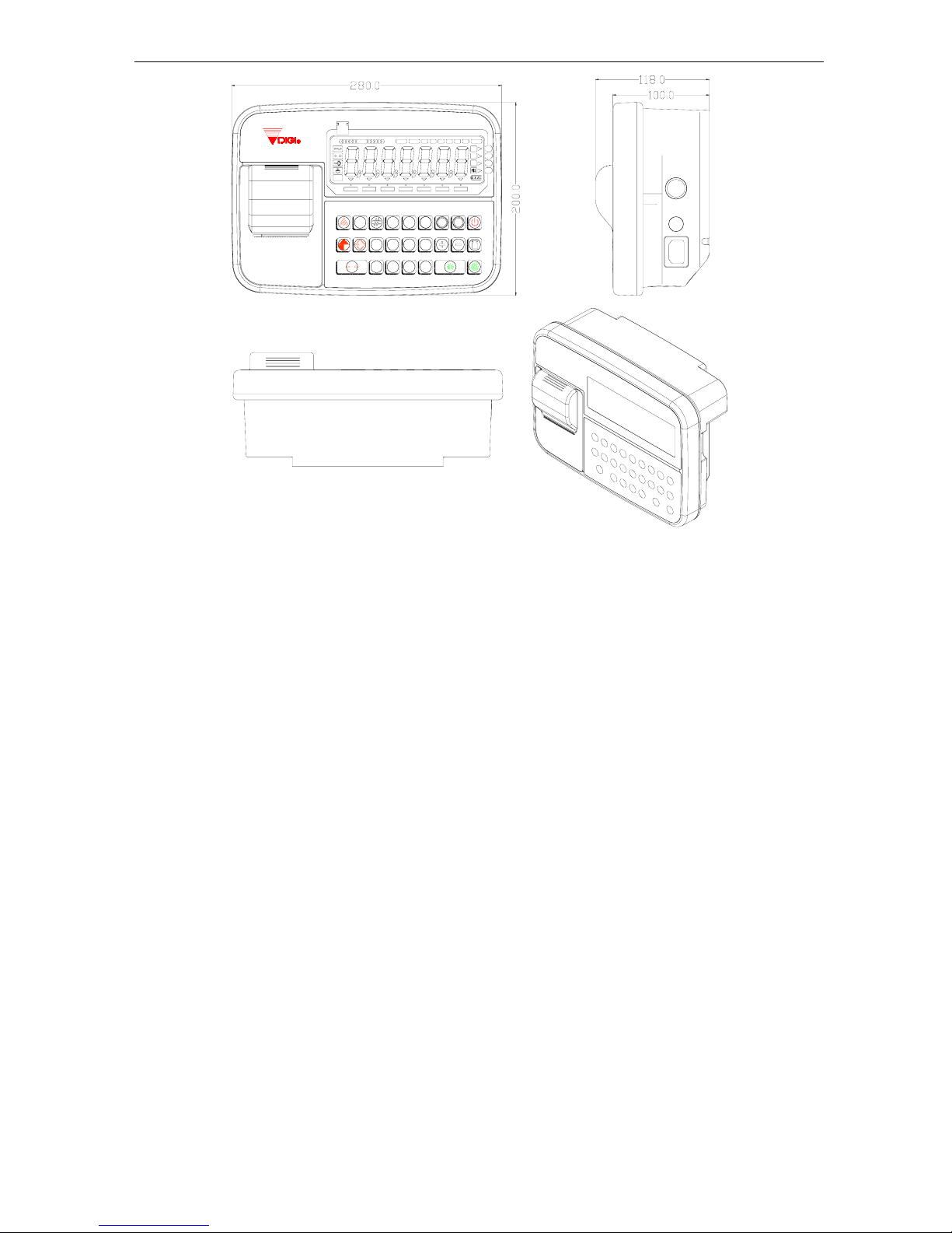
z Overall Dimensions : 280mm (L) x 200mm(W) x 118mm(H)
1.2. Features
1.2.1. Indicators
z 4 types selectable unit symbol: g, kg, lb and PCS
z 4 piece set Point Indicator symbol (OV1,OV2,OV3,OV4)
z 11 class drawing display for point checking indicator.
z And 21 indicators for other symbols.
z 1 battery indicator.
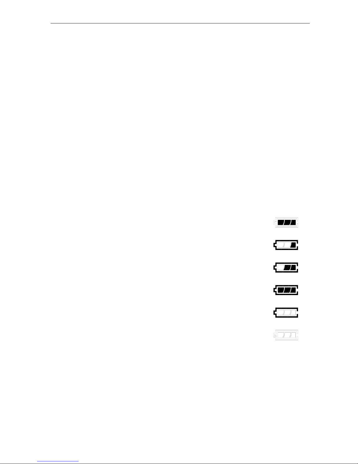
1.2.2. Battery Indicator
There are 3 levels in battery indicator to display the volume of battery
power.
Fig.6
Fig.5
Fig.4
Fig.3
Fig.2
Fig.1
z Fig. 1 means battery not installed, and AC power linked only.
z Fig. 2 ~ Fig. 4 shows the volume of rechargeable battery in charging or
discharging mode.
z Fig. 5 means battery lower, Fig. 6 is a flash indicator will keep about 2
minutes if still using battery for power supply only, then display will auto
off.
z When the AC power is connected, the battery indicator will keep light
on display although the On/Off key is pressed for display off. The
battery will be kept in charging mode till the AC plugged off.
1.2.3. Interface
z 1 RS-232C port
z Set point output port
z 14 Pin DDK Load Cell connecter
1.2.4. Printer (Optional):
Built-in dot matrix printer with English or Chinese printing
Page No. 1
Page 5

DI-600 Operation Manual
1.2.5. Load Cell:
Exiting Voltage : 12V (DC)
Sensitivity (Selectable) : 0.4mV/V ~3.5mV/V
Input impedance : 350 Ohm
Maximum number of L/C : Max. 8 pcs L/C connected in parallel (350 Ohm only)
1.2.6. Housing: New design
1.2.7. Calibration: Software Calibration
1.2.8. Power Source: AC 220V (+10%, -15%) 50/60Hz
Or recharge battery 12V 2.7AH
1.2.9. Rechargeable Specification: 12V 2.7AH
a) Continuous Usage:
z 8 Hours for 1 L/C connected & printer installed but not printing when fully charged.
z Or 5 hours for 8 L/C connected & printer installed but not printing when fully
charged.
z 10 hours for 1 L/C connected & no printer when fully charged.
z Or 6 hours for 8 L/C connected & no printer when fully charged.
z Or 1 hour for continuously printing.
b) Charging specification
z Normally the charging current will be about 1.2A, but it depends on how much
power remained when charging.
z Please ensure more than 8 hours for charging.
1.2.10. Operation Condition:
Temperature: 0 - 40 ℃
Humidity: < 85 % RH
1.3. Main Functions
z Base Unit selection : kg or g
z Unit conversion : between kg and lb
z Counting mode
z Weight & Quantity data can be output via RS-232 port to PC
1.4. Overall View
1.4.1. Layout & Dimension
Page No. 2
Page 6
DI-600 Operation Manual
COUNT
SET CAL SP1 SP2 SP3 SP4
TOTALCHECK
OK
LOW HIGH
O
kg
lb
g
MEM
0
0
CH
T
C
1 2
3
4
5
7
8
6
9
SlbM
DI- 6 00
Page No. 3
Page 7
DI-600 Operation Manual
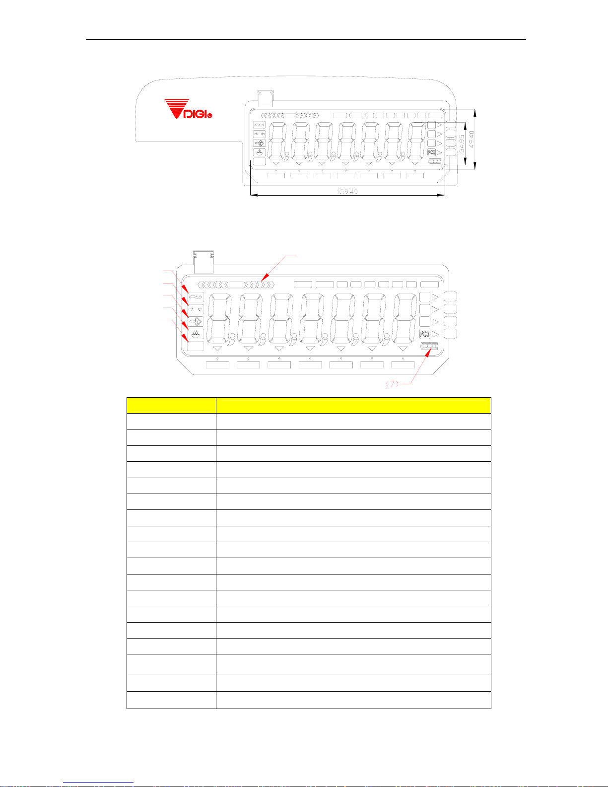
1.4.2. Display Panel
DI-600
OK
MEM
O
LOW
g
kg
lb
SP2
HIGH
CHECK COUNT
SET SP1CAL SP3 S P4
TOTAL
SM1
SM2
SM3 SM 4
SM5 ALMHOLD
OS4
OS3
OS2
OS1
1.5. Keyboard & Display Layout and Function
1.5.1. Indicators
OK
MEM
O
LOW
SP2
HI GH
CHECK COUNT
SET SP1CAL
g
kg
lb
SP3 SP4
TOTAL
⑴
⑵
⑷
⑶
⑸
⑹
SM1
SM2
SM3 SM 4
SM5 HOLD AL M
OS4
OS3
OS2
OS1
Indicator
Definition & Function
(1) Stable
Light on when weight is stable
(2) Zero
Light on when weight display is zero and stable
(3) Tare
Light on when tare weight is set
(4) Net
Display value is net weight indicator.
(5) MEM
Memory indicator. Light on when accumulated
(6) Weight range
Weight range checking indicator
(7) Battery
Battery indicator
CHECK
Light on when in weight checking mode
COUNT
Counter Mode
SET
Data set mode
CAL
Light on when perform the system calibration or spec setting
SP1,SP2,SP3,SP4
Set point indicator
TOTAL
Total Weight accumulation display mode indicator.
SM1,SM2,SM3,SM4
Set point memory group by used indicator.
HOLD
Display hold mode
ALM
Set point alarm is “on”, when it is flash the alarm is at filling mode.
When it is light on, means at the check mode.
g ,kg ,lb
Weight unit
PCS
Counter unit
Page No. 4
Page 8
DI-600 Operation Manual
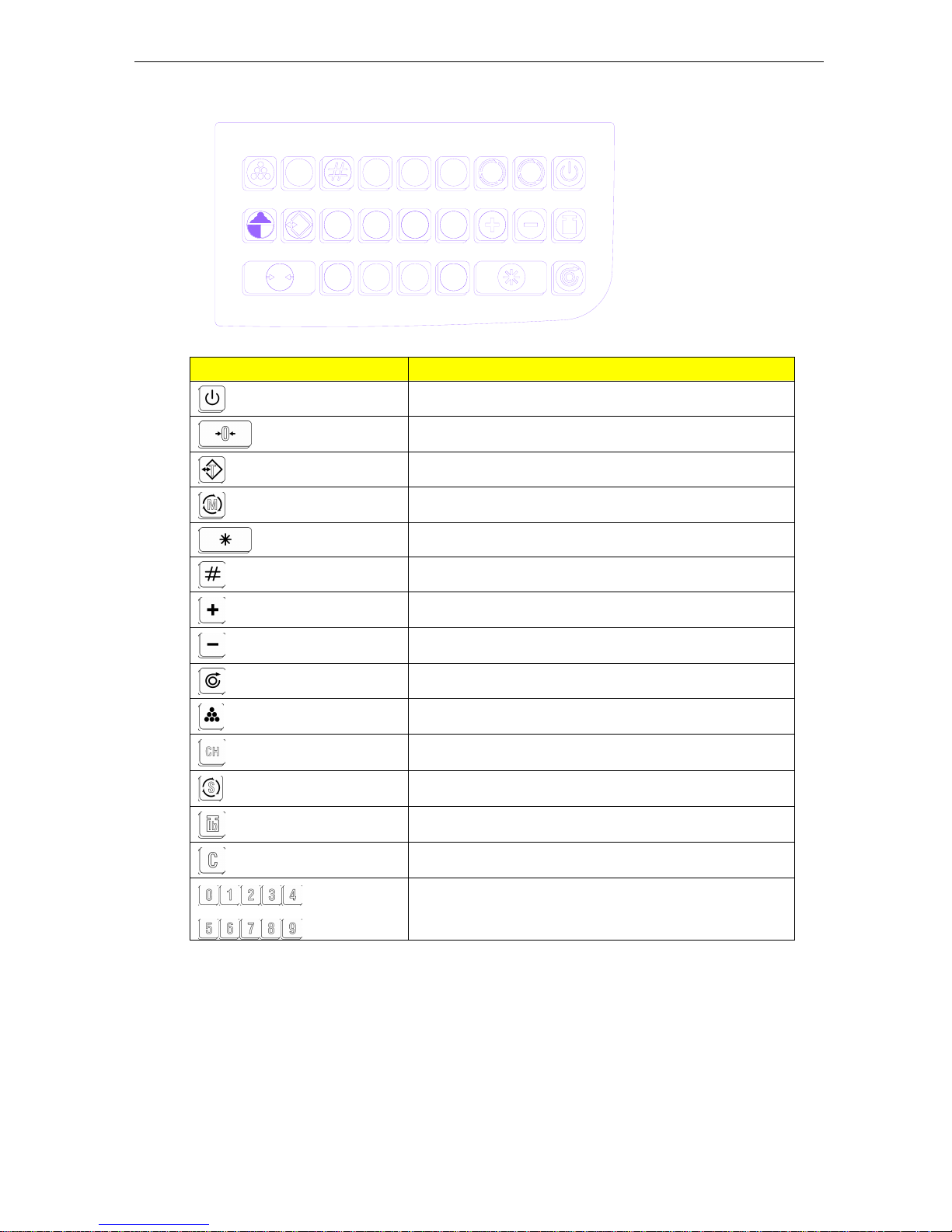
1.5.2. Keyboard
65
4
0
C
1
0
2
3
CH
7
9
8
T
lb
S M
Key Function
[ On/Off]
Switch the display On/Off
[ Re-Zero ]
Set the weight to zero
[ Tare ]
Set tare value or escape form program mode
[ Mode]
Set point setting Mode → Weighing Mode change
[ Enter ]
(1) Sent the data to PC.
(2) Calculate unit weight in sample quantity setting mode
[ Number ]
Set code number.
[Plus]
Weight addition.
[Minus]
Modification total weight.
[Feed]
The print paper feed
[Count]
Entry counting Mode
[Check]
Entry check mode and hold switch
[MEM SEL]
Set point memory select (1~4)
[Unit]
Switch the weight unit.
[Clear]
Clear data
[Numeric]
Number key
1.6. Hardware
Microcomputer : MCS 51 single microprocessor (Winbond w78e58 8 bit)
Display Drive : HT 1620
LCD Display : MODEL GD-587
A/D Board : New design A/D
Page No. 5
Page 9

DI-600 Operation Manual
Page No.
5
2. Main Operation
2.1. Power On
INDICATION FLAG : ( ▼ EXPRESS BRIGHT, SPARKLING )
(1) Zero (2) Net (3) STA (4) Count (5) Check (6) MEM (7) OS1 (8) OS2 (9) OS3 (10) OS4
(11) Hold (12) ALM
Indicators
Operation Key Weight
1 2 3 4 5 6 7 8 9 10 11 12
Remarks
Press [On/Off] Key
di-600
First display the
Indicator model,
Ur 1.00 Display version No.
0000000
1111111
:
9999999
▼ ▼
Segment checking
0.000
kg ▼ ▼
Weighting mode
Note: The segment checking mode can be skipped If [Re-Zero] key pressed after power on.
2.2. Power OFF
INDICATION FLAG : ( ▼ EXPRESS BRIGHT, SPARKLING )
(1) Zero (2) Net (3) STA (4) Count (5) Check (6) MEM (7) OS1 (8) OS2 (9) OS3 (10) OS4
(11) Hold (12) ALM
Indicators
Operation Key Weight
1 2 3 4 5 6 7 8 9 10 11 12
Remarks
W
eighing mode 0.000
kg ▼ ▼
Press [On/Off] Key
2.3. One Touch Tare
INDICATION FLAG : ( ▼ EXPRESS BRIGHT, SPARKLING )
(1) Zero (2) Net (3) STA (4) Count (5) Check (6) MEM (7) OS1 (8) OS2 (9) OS3 (10) OS4
(11) Hold (12) ALM
Indicators
Operation Key Weight
1 2 3 4 5 6 7 8 9 10 11 12
Remarks
Weighing mode 0.000
kg ▼ ▼
Load Tare weight
2.500 kg ▼ Ex: tare 2.5kg
Press [Tare] Key [ tare]
0.000 kg
▼ ▼
Back to Weighing
mode
2.4. Digital tare
INDICATION FLAG : ( ▼ EXPRESS BRIGHT, SPARKLING )
(1) Zero (2) Net (3) STA (4) Count (5) Check (6) MEM (7) OS1 (8) OS2 (9) OS3 (10) OS4
(11) Hold (12) ALM
Indicators
Operation Key Weight
1 2 3 4 5 6 7 8 9 10 11 12
Remarks
Weighing mode 0.000
kg ▼ ▼
Enter tare weight
value (Ex: 2.5kg)
[2][5][0][0]
2.500 kg ▼
Using number key.
Example:2.5kg
Press [Tare] Key [ Tare]
0.000 kg
▼ ▼
Back to weighing
mode
Page 10

DI-600 Operation Manual
Page No.
6
2.5. Tare Clear
INDICATION FLAG : ( ▼ EXPRESS BRIGHT, SPARKLING )
(1) Zero (2) Net (3) STA (4) Count (5) Check (6) MEM (7) OS1 (8) OS2 (9) OS3 (10) OS4
(11) Hold (12) ALM
Indicators
Operation Key Weight
1 2 3 4 5 6 7 8 9 10 11 12
Remarks
Weighing mode -2.500
kg ▼ ▼ ▼
Press [Tare] key [ Tare ]
0.000
kg ▼ ▼
Clear tare data and
back to weighing
mode
2.6. Date and Time Setting
INDICATION FLAG : ( ▼ EXPRESS BRIGHT, SPARKLING )
(1) Zero (2) Net (3) STA (4) Count (5) Check (6) MEM (7) OS1 (8) OS2 (9) OS3 (10) OS4
(11) Hold (12) ALM
Indicators
Operation Key Weight
1 2 3 4 5 6 7 8 9 10 11 12
Remarks
W
eighing mode 0.000
kg ▼ ▼
Press [Mode] [Mode]
P. totAL
Press [Mode] [Mode]
C. totAL
Input Date
(Ex: 2002.6.9)
[0][2][0]
[6][0][9]
d.Y. N. d
d.020401
d.020609
Press [Enter] Key [Enter]
t. HH-NN
t. 00-00
Input TIME
(Ex: 18:26)
[1][8][2][6]
t. 18-26
Press [Enter] key [Enter]
S.PoInt1
Press [Tare] return
t
o weighing mode
[ Tare ]
0.000
kg ▼ ▼ ▼
Escape to weighing
mode
Note: If SPEC 07 bit3=1, the clock function will be disabled.
The date format is yy-mm-dd, the time format is HH-MM, date format can be set on
SPEC18 Bit0~1.
2.7. Date & Time Recall
INDICATION FLAG : ( ▼ EXPRESS BRIGHT, SPARKLING )
(1) Zero (2) Net (3) STA (4) Count (5) Check (6) MEM (7) OS1 (8) OS2 (9) OS3 (10) OS4
(11) Hold (12) ALM
Indicators
Operation Key Weight
1 2 3 4 5 6 7 8 9 10 11 12
Remarks
Weighing mode 0.000
kg ▼ ▼
Press [Time] key [ Time ]
t. 18-26
▼ ▼
At this time must be
the weigh is 0 and
total weight as
same.
Press [Date] key [ Date ]
d.020618
▼ ▼
Press [Tare] key [ Tare ]
0.000
kg ▼ ▼
Return to weight
mode.
Page 11

DI-600 Operation Manual
Page No.
7
2.8. Grand Total Data Clear
3.8.1. Weight Grand Total Clear
INDICATION FLAG : ( ▼ EXPRESS BRIGHT, SPARKLING )
(1) Zero (2) Net (3) STA (4) Count (5) Check (6) MEM (7) OS1 (8) OS2 (9) OS3 (10) OS4
(11) Hold (12) ALM
Indicators
Operation Key Weight
1 2 3 4 5 6 7 8 9 10 11 12
Remarks
Weighing mode 0.000
kg ▼ ▼
Press [Mode] key [Mode ]
P. totAL
12.0235
Press [Clear] key [Clear]
0.000
Press [Enter] key [Enter]
C. totAL
Press [Tare] key [Tare]
0.000
kg ▼ ▼
Escape to
weighting mode
Note: SPEC 20 Bit1 should be set as 0 to enable the grand total operation.
3.8.2. Quantity Grand Total Clear
INDICATION FLAG : (▼ EXPRESS BRIGHT, SPARKLING)
(1) Zero (2) Net (3) STA (4) Count (5) Check (6) MEM (7) OS1 (8) OS2 (9) OS3 (10) OS4
(11) Hold (12) ALM 8293225 13964731996
Indicators
Operation Key Weight
1 2 3 4 5 6 7 8 9 10 11 12
Remarks
Weighing mode 0.000
kg ▼ ▼
Press [Mode] key [Mode ]
P. totAL
Press [Mode] [Mode]
C. totAL
12899
Press [Clear] key [Clear]
0
Press [Enter] key [Enter]
d. Y.N.d
Press [Tare] key [ Tare ]
0.000
kg ▼ ▼
Escape to
weighting mode
Note: SPEC 20 Bit 0 should be set as 0 to enable the quantity grand total operation.
2.9. Serial number setup
INDICATION FLAG : ( ▼ EXPRESS BRIGHT, SPARKLING )
(1) Zero (2) Net (3) STA (4) Count (5) Check (6) MEM (7) OS1 (8) OS2 (9) OS3 (10) OS4
(11) Hold (12) ALM
Indicators
Operation Key Weight
1 2 3 4 5 6 7 8 9 10 11 12
Remarks
Weighing mode
0.000
kg ▼ ▼
Press [ # ] [ # ]
C.000000
▼ ▼
Input CODE
number value
[1][8][5]
[6][2][6]
C.185626
▼ ▼
Example: the serial
code is 185626
Press [Enter] key [ENTER]
0.000
kg ▼ ▼
Back to weighting
mode
Note: This serial number can be used for print.
Page 12

DI-600 Operation Manual
Page No.
8
2.10. Weight Unit Conversion
INDICATION FLAG : ( ▼ EXPRESS BRIGHT, SPARKLING )
(1) Zero (2) Net (3) STA (4) Count (5) Check (6) MEM (7) OS1 (8) OS2 (9) OS3 (10) OS4
(11) Hold (12) ALM
Indicators
Operation Key Weight
1 2 3 4 5 6 7 8 9 10 11 12
Remarks
Weighing mode
0.000
kg ▼ ▼
1.000
kg
▼
Put 1.0kg
Press [lb] key
[ lb]
2.204
Lb
▼
Display in lb
Press [lb] key
[ lb]
1.000
kg
▼ Display in kg
Note: Set the SPEC 19 Bit 0 as 0 to enable this function.
2.11. Set Point Value Setting & S. Memory Recall
System can be set 5 groups of set-point value, each group can be registered 4 points data.
Before be use this function, we should program the group data of set point into memory first.
When the weight exceeds the first point value, the indicator OS1 will be light.
When the weight exceeds the second point values, the indicator OS1 and OS2 will be light.
When the weight exceeds the third point values, the indicator OS1, OS2 and OS3 will be light.
When the weight exceeds the fourth point values, OS1, OS2, OS3 and OS4 will be light.
2.11.1. Set Point Value Setting
INDICATION FLAG : (▼ EXPRESS BRIGHT, SPARKLING)
(1) Zero (2) Net (3) STA (4) Count (5) Check (6) MEM (7) OS1 (8) OS2 (9) OS3 (10) OS4
(11) Hold (12) ALM
Indicators
Operation Key Weight
1 2 3 4 5 6 7 8 9 10 11 12
Remarks
Weighing mode 0.000
kg ▼ ▼
Press [M][M][M][M]
[M][M]
[M][M]
S.PoInt1
6.000
kg ▼ ▼
▼
SM1, SP1 data Set.
SM1 bright
Input value
(Ex: 1.000kg)
[1][0][0][0]
1.000
kg ▼ ▼
▼ ▼
SP1 Value is 1 kg
Press [Enter] key [Enter]
S.PoInt2
6.000
kg ▼ ▼
▼
SM1, SP2 data Set.
SM1 bright
Input number value
(Example: 2.000kg)
[2][0][0][0]
2.000
kg ▼ ▼
▼
▼
SP2 value is 2 kg
Press [Enter] key [Enter]
S.PoInt3
6.000
kg ▼ ▼
▼
SM1, SP3 data Set.
SM1 bright
Input number value
(Example: 3.000kg)
[3][0][0][0]
3.000
kg ▼ ▼
▼ ▼
SP3 value is 3 kg
Press [Enter] key [Enter]
S.PoInt4
6.000
kg ▼ ▼
▼
SM1, SP4 data Set.
SM1 bright
Input number value
(Example: 4.000kg)
[4][0][0][0]
4.000
kg ▼ ▼
▼ ▼
SP4 value is 4 kg
Press [Enter] key [Enter]
S.PoInt1
6.000
kg ▼ ▼
▼
SM2, SP1 data Set.
SM2 bright
Repeat above
operation
:
:
SM2~SM5 data
Press [Tare] key [Tare]
0.000
kg ▼ ▼
Weighing mode
Note: The value of each set point should be assure SP1 less then SP2, SP2 less then SP3,
SP3 less then SP4 and SP4 less then full capacity.
Page 13

DI-600 Operation Manual
Page No.
9
2.11.2. Set Point Memory Recall
INDICATION FLAG : ( ▼ EXPRESS BRIGHT, SPARKLING )
(1) Zero (2) Net (3) STA (4) Count (5) Check (6) MEM (7) OS1 (8) OS2 (9) OS3 (10) OS4
(11) Hold (12) ALM
Indicators
Operation Key Weight
1 2 3 4 5 6 7 8 9 10 11 12
Remarks
Weighing mode 0.000
kg ▼ ▼
▼
Press [ S ] [ S ]
SEL. S. 1
▼ ▼
Input number of
SM (1~5) (Ex: 2)
[ 2 ]
SEL. S. 2
▼ ▼
Select activity SM2
Press [Enter] key [Enter]
0.000
kg ▼ ▼
▼
Weighting mode,
Weight is stabled
Note: The numeric keys 1~5 are available only for this operation.
2.11.3. Set-Point Check and Alarm Mode Select
There is Filling or Check Weighing methods for application of Set-Point Alarm Function.
z Filling Application
Operator can set the certain weight point to judge the filled weight reached or over target
range. The target range can be determined between 2 set-point (set-point 2 and set-point
3), the continuous and fast alarm will alert when weight is reached target weighing range.
And the range of Set-point 1 to 2 and Set-point 3 to 4 can be programmed as fine
adjustment range.
(Min.) (Max.)
Near Min. Target Over Max.
Zero Set-point 1 Set-point 2 Set-point 3 Set-point 4 Capacity
Note: means slow alarm and means fast alarm.
Indicators
Operation Key Weight
1 2 3 4 5 6 7 8 9 10 11 12
Remarks
Weighing mode 0 .000
kg ▼ ▼ ▼
Press [ CH ] [ CH ]
ALA. FIL
▼ ▼
Press [Enter] [Enter]
0.000
kg ▼ ▼ ▼
Entry weighting
mode, filling check
alarm on.
Note: Please enable the set-point alarm via setting of SPEC 06 bit 1.
z Weight Check Application
Operator can set the allowable error weight range between 2 set-points (set-point 2 and
set-point 3), and the range of Set-point 1 to 2 and Set-point 3 to 4 can be programmed as
out of range.
(Min.) (Max.)
Out Allowable Out
Zero Set-point 1 Set-point 2 Set-point 3 Set-point 4 Capacity
Note: means slow alarm and means fast alarm.
Page 14

DI-600 Operation Manual
Page No.
10
Indicators
Operation Key Weight
1 2 3 4 5 6 7 8 9 10 11 12
Remarks
W
eighing mode 0.000
kg ▼ ▼ ▼
Press [ CH ] [ CH ]
ALA. FIL
▼ ▼
Press [ CH ] [ CH ]
ALA. CH
▼ ▼
Press [enter] key [Enter]
0.000
kg ▼ ▼ ▼
▼
Entry weighting
mode, weight
check alarm on
Note: Please enable the set-point alarm via setting of SPEC 06 bit 1.
z Alarm Sound Off
Indicators
Operation Key Weight
1 2 3 4 5 6 7 8 9 10 11 12
Remarks
W
eighing mode
0.000
kg ▼ ▼ ▼
Press [ CH ] [ CH ]
ALA. FIL
▼ ▼
Press [ CH ] [ CH ]
ALA. CH
▼ ▼
Press [ CH ] [ CH ]
ALA.OFF
▼ ▼
A
larm off
Press [Enter] key [Enter]
0.000
kg ▼ ▼ ▼
Back weighing mode
2.11.4. Weight Check Bar of Set-Point
The check bar can be separated as three phases of display range.
First phase corresponds to the range between set-point 1 and 2.
Second phase corresponds to the range between set-point 2 and 3.
Third phase equals to the range between set-point 3 and 4.
The first and third range has 5 grades of
indicators for each, and one grade of indicator
equals to 20% of weight range between
set-point 1 & 2 or 3 & 4.
Ex: The system once increment is 5 g.
Set-point data:
Set-point 1 = 1.000kg, Set-point 2 = 2.000kg
Set-point 3 = 4.000kg, Set-point 4 = 5.000kg
Display Sample Weight
Fig 1
1.000 ~ 1.195 kg
Fig 2
1.800 ~ 1.995 kg
Fig 3
2,000 ~ 3,995 kg
Fig 4.
4.800 ~ 4.395 kg
Fig 5
Over 5.000kg
LOW
OK
CHECK
HI GH
LOW
OK
CHECK
HI GH
LOW
OK
CHECK
HI GH
LOW
OK
CHECK
HI GH
LOW
OK
CHECK
HI GH
LOW
OK
CHECK
HI GH
Fig. 1
Fig. 2
Fig. 3
Fig. 4
Fig. 5
SP1 SP2 SP3 SP4
Page 15

DI-600 Operation Manual
Page No.
11
2.12. Counting Mode
DI-600 has counting function. It can set the sample quantity.
The default sample quantity is 10, or you can set the certain quantity as you need.
2.12.1. Key Entry Quantity
INDICATION FLAG : ( ▼ EXPRESS BRIGHT, SPARKLING )
(1) Zero (2) Net (3) STA (4) Count (5) Check (6) MEM (7) OS1 (8) OS2 (9) OS3 (10) OS4
(11) Hold (12) ALM
Indicators
Operation Key Weight
1 2 3 4 5 6 7 8 9 10 11 12
Remarks
W
eighing mode
0.000
kg ▼ ▼ ▼
Load10 pcs sample
0.025
kg
▼
▼
Counting mode
Press [ Count ] [ Count ]
10
PCS
▼ ▼ ▼
Remove all
0
PCS ▼ ▼ ▼ ▼
Put one package
100
PCS
▼ ▼ ▼
Remove all
0
PCS ▼ ▼ ▼ ▼
Press [ C ] key [ C ]
0.000
kg ▼ ▼ ▼
Weighing mode.
2.12.2. Sample Quantity Setting
INDICATION FLAG : ( ▼ EXPRESS BRIGHT, SPARKLING )
(1) Zero (2) Net (3) STA (4) Count (5) Check (6) MEM (7) OS1 (8) OS2 (9) OS3 (10) OS4
(11) Hold (12) ALM
Indicators
Operation Key Weight
1 2 3 4 5 6 7 8 9 10 11 12
Remarks
Weighing mode
0.000
kg ▼ ▼ ▼
Press [ Count ] [Count]
10
PCS ▼ ▼ ▼
▼
Key in quantity [8][5][0]
850
PCS ▼ ▼ ▼
▼
Press [Enter] key [Enter]
0.000
kg ▼ ▼ ▼
Weighing mode
2.12.3. Sample Quantity Modification and Print Receipt
INDICATION FLAG : ( ▼ EXPRESS BRIGHT, SPARKLING )
(1) Zero (2) Net (3) STA (4) Count (5) Check (6) MEM (7) OS1 (8) OS2 (9) OS3 (10) OS4
(11) Hold (12) ALM
Indicators
Operation Key Weight
1 2 3 4 5 6 7 8 9 10 11 12
Remarks
Weighing mode
0.000
kg ▼ ▼ ▼
Load10 pieces
0.025
kg
▼
▼
Into counting mode
Press [Count] [ Count ]
10
PCS
▼ ▼ ▼
Remove
0
PCS ▼ ▼ ▼ ▼
Press [ Count ] [ Count ]
10
PCS ▼ ▼ ▼ ▼ ▼
Weight is “0”
Key in quantity [1][0][0][0]
1000
PCS ▼ ▼ ▼
▼
EX: 1000
Press [Enter] key [Enter]
0.000
kg ▼ ▼ ▼
Load 1000 pieces
1.525
kg
▼
▼
Counting mode
Press [ Count ] [ Count ]
1000
PCS
▼ ▼ ▼
Put one package
2000
PCS
▼ ▼ ▼
Press [Enter] key [Enter]
2000
PCS
▼
▼
Print receipt
Remove all
0
PCS ▼ ▼ ▼ ▼
Press [ C] key [ C ]
0.000
kg ▼ ▼ ▼
Weighing mode.
Page 16

DI-600 Operation Manual
Page No.
12
Same of Printed Receipt:
2.13. Accumulation Operation
2.13.1. Weight Accumulation
INDICATION FLAG : ( ▼ EXPRESS BRIGHT, SPARKLING )
(1) Zero (2) Net (3) STA (4) Count (5) Check (6) MEM (7) OS1 (8) OS2 (9) OS3 (10) OS4
(11) Hold (12) ALM
Indicators
Operation Key Weight
1 2 3 4 5 6 7 8 9 10 11 12
Remarks
W
eighing mode 0.000
kg ▼ ▼ ▼
Load weight on
25.500
kg
▼
▼
EX: 25.50kg
Press [ + ] key [ + ]
Add. 1
25.500
kg
▼
▼ ▼
Or auto print weight
receipt
W
ait for printing end
25.500
kg ▼ ▼ ▼
Auto return to
weighing mode.
Remove weight
0.000
kg ▼ ▼ ▼ ▼
Load weight on
15.500
kg
▼
▼ ▼
Ex: 15.50kg
Press [ + ] key [ + ]
Add. 2
41.000
kg
▼
▼ ▼
Or auto print weight
receipt
W
ait for printing end
15.500
kg ▼ ▼ ▼
Auto return to
weighing mode.
Remove weight
0.000
kg ▼ ▼ ▼ ▼
Press [ + ] key [ + ]
tot. 2
41.000
kg▼ ▼ ▼ ▼
Display the total
weights stored
Press [ C ] key
O
r
Press [ Enter ]
[ C ]
[ Enter ]
0.000
kg ▼ ▼
Here you can clear
or print the total
value and grand
total operation.
W
ait for printing end
0.000
kg ▼ ▼ ▼
Return to weighting
mode.
Note: After printed the total value, accumulator will be clear to “0”, in meantime this total will be
added into grand total.
02 06-18 15:21
CODE: 123456
PIECES: 2000
------------------------------
Page 17

DI-600 Operation Manual
Page No.
13
2.13.2. Quantity Accumulation
INDICATION FLAG : ( ▼ EXPRESS BRIGHT, SPARKLING )
(1) Zero (2) Net (3) STA (4) Count (5) Check (6) MEM (7) OS1 (8) OS2 (9) OS3 (10) OS4
(11) Hold (12) ALM
Indicators
Operation Key Weight
1 2 3 4 5 6 7 8 9 10 11 12
Remarks
Weighing mode 0.000
kg ▼ ▼ ▼
Load 10 pieces
0.025
kg
▼
▼
Ex: 10 pcs
Press [ Count ] [ Count ]
10
PCS
▼
▼
Remove all
0
PCS ▼ ▼ ▼
Load one bag
200
PCS
▼
▼
Ex: 200 pieces
Press [ + ] [ + ]
Add. 1
200
PCS
▼
▼ ▼
With printing the
accumulated data
Remove all
0
PCS ▼ ▼ ▼ ▼
Put one bag
300
PCS
▼
▼
Ex: 300 pieces
Press [ + ] [ + ]
Add. 2
500
PCS
▼
▼ ▼
With printing the
accumulate data
Remove all
0
PCS ▼ ▼ ▼ ▼
Press [ + ] key
again
[ + ]
tot. 2
500
PCS ▼ ▼ ▼ ▼
Display the total
PCS.
Press [ C ] key
or
Press [ Enter ]
[ C ]
[ Enter ]
0
PCS
▼ ▼
Hear you can clear
or print the total
Wait for printing
end
0
PCS ▼ ▼ ▼
Return to weighing
mode.
Note: After printed the total value, accumulator will be clear to “0”, in meantime this total will be
added into grand total.
Sample of Printed Receipt:
02 06-18 15:21
# 123456
+ 200 PCS
# 123456
+ 300 PCS
A 0002
T 500 PCS
02 06-18 15:28
# 123456
+ 25.500kg
# 123456
+ 15.500kg
A 0002
T 41.000kg
Page 18

DI-600 Operation Manual
Page No.
14
2.14. Grand Total Check and Print
INDICATION FLAG : ( ▼ EXPRESS BRIGHT, SPARKLING )
(1) Zero (2) Net (3) STA (4) Count (5) Check (6) MEM (7) OS1 (8) OS2 (9) OS3 (10) OS4
(11) Hold (12) ALM
Indicators
Operation Key Weight
1 2 3 4 5 6 7 8 9 10 11 12
Remarks
Weighing mode 0.000
kg ▼ ▼
Press [ Mode ] [ Mode ]
P.tOtAL
41.000
kg ▼ ▼
Ex: 41.000kg,
Auto print grand
total weight.
Press [ Enter ] [ Enter ]
C.tOtAL
500
PCS ▼ ▼
Ex: 500PCS,
Auto print grand
total quantity.
Press [ Enter ] [ Enter ]
D
02.06.1
8
▼ ▼
Press [ Tare ] key [ Tare ]
0
kg ▼ ▼ ▼
Wighting mode.
Note: After printed the grand total value, memory will be clear to “0”.
Sample Receipt of Grand total Printed. (English)
2.15. Printed Ticket Sample
02 06-18 15:28
GRAND TOTAL
GT 41.000kg
---------------------------------
-
02 06-18 15:28
GRAND TOTAL
GT 500PCS
---------------------------------
-
02 06-18 10:16
CODE: 123456
GROSS: 1.000kg
NET: 0.520kg
TARE: 0.480kg
--------------------------
DI-600 PRINT
Page 19

DI-600 Operation Manual
3. Error Message
3.1. Error Message List & Solution
DI-600 will display error message if improper operation is performed or system defect.
No. Display Contents Solution
01 OF
Over Flow, weight is over full
capacity.
Remove some weight form platform.
02 LO
Lower weight, weight value is
lower then limit of display
mask weight.
Add some weight or restart the
indicator
03 nOt Ad
A/D error
Check the A/D board and load cell are
defective or not.
04 zErO Er
Zero Point error, not at zero
point or over start range
Remove weight on platter or restart
the scale, otherwise calibrate it again.
05 Add. OF
Accumulated data over flow Clear the total data and operate again.
06 GrA. OF
Grand Total data over flow Clear the grand total.
If the problems still can not be resolved according to above information, please contact to our
local dealer or Technical Service Dept. of Shanghai Teraoka via the information which described
on manual cover.
Page No.
15
Page 20

DI-600 Service Manual
4. Interface & Protocol
4.1. Load Cell Connecter
z DDK-14PIN connector.
z Allows to parallel connected 8 load cells with 350 Ohm impedance for each.
z Regulated 6 wire connection with power feedback signal.
z Exciting voltage: DC 12V, 280 mA.
z Pin connection:
Pin No. Signal Wire Color Pin No. Signal Wire Color
1 RS+ Orange 8 F.GND
Wire Layer
2 RS- Blue 9 NC
3 V+ Red 10 NC
4 V - White 11 NC
5 GND Black 12 NC
6 IN+ Green 13 NC
7 IN - Yellow 14 NC
4.2. RS-232C Port
The Baud Rate of RS-232C setting is selectable in SPEC 04, and the other parameters are fixed
as following:
(1) Data Length : 8 bit
(2) Stop Bit: : 1 bit
(3) Parity Bit : No
4.2.1. RS-232 Cable Connection
DI-600 (D-Din 8Pin) PC (D-SUB 9 Pins)
Pin No. Signal Name Pin No Signal Name
1
NC 1 NC
2
GND 2 RXD
3
NC 3 TXD
4
RXD 4 DTR
5
TXD 5 GND
6
DTR 6 DSR
7
NC 7 RTS
8
NC 8 CTS
9
SHIELD
9NC
Page No. 23
Page 21

DI-600 Service Manual
4.2.2. RS-232 Protocol
4.2.2.1. Text Command
Data Type Code Contents Hex Data
CR End of data 0DH
Terminal Code
LF End of Text 0AH
0 ~ 9 Numeric data (30H~39H)
- (Minus) Minus sign 2DH
. (Period) Period 2EH
Data
, (Comma) Comma 2CH
0 Net Weight 30H
4 Tare Weight 34H
Header Code
C Quantity data 43H
NUL Stable 00H
Stable Sign
SOH Un-stable 01H
4.2.2.2. Data Format
SPEC03 Bit 0 for Header Code, SPEC03 Bit 1 for Weight Stable sign definition.
a) Without header code & Without weight stable sign (Total 19 Bytes)
Net Weight CR Tare Weight CR LF
8 Byte 1byte 8 Byte 1 Byte 1 Byte
b) Without header code & With weight stability sign (Total 21 Bytes)
Stable
status
CR Net Weight CR Tare Weight CR LF
1 Byte 1 Byte 8 Byte 1byte 8 Byte 1 Byte 1 Byte
c) With header code & Without weight stability code (Total 21 Bytes)
Header
status
Net Weight CR
Header
status
Tare Weight CR LF
1 Byte 8 Byte 1byte 1 Byte 8 Byte 1 Byte 1 Byte
d) With header code and weight stability code (Total 23 Bytes)
Stable
status
CR
Header
Code
Net
Weight
CR
Header
Code
Tare
Weight
CR LF
1 Byte 1 Byte 1 Byte 8 Byte 1byte 1 Byte 8 Byte 1 Byte 1 Byte
e.g.) With Header code and weight stability code
Net weight =-1,2340 Tare weight = 0,450 weight status = stable
NUL CR 0 - 0 1 , 2 3 0 CR
4 0 0 0 , 4 5 0 CR LF
Note 1: The data format consists of (header code), minus/plus sigh, numeric data and
decimal data. If weight data is minus, -(2DH) is added after header data. If weight is
plus data, 0(30H) is output.
Note 2: The data is aligned form right except plus/minus sign if weight data are less then 5
digits.
Note 3: When weight is over the capacity, the following data is output:
0OV00000CR4???????CRLF (With Header Code)
Page No. 24
Page 22

DI-600 Service Manual
4.2.2.3. Communication Method
Communication method can be selected as Stream (continuous), Manual and Command by
specification settings.
a) Stream (continuous output)
Data will transmit to PC side continuously, and the function of SPEC 03 bit 0 is disabled.
b) Manual Command
Data will output after ↑ key pressed, customer may select to transmit the data right away
or hold the command until weight becomes stable through the SPEC setting. If weight not
stable within certain interval, error message “ERR C” will appear on display.
Data Flow (Stream Output after Weight Stable):
PC Side DI-600 Side
Weight Stable
?
X. Seconds
Time Out
Yes
Manual Command
Yes
No
No
Text
Page No. 25
Page 23

DI-600 Service Manual
c) Command Mode
Data will be sent out after received command (ACK 06H) form external device (Ex. PC).
If PC required data from DI-600 side, PC should transmit an ACK signal to DI-600 , after
DI-600 received the ACK signal, DI-600 would transmit the weight data to PC
SPEC setting can define the data It is alter to send the weight data right away or to hold
the command unit weight. Become stable. If weight is not back to stable condition within
the certain interval, DI-600 transmits NAK (15H) to PC.
Note) If ACK signal is sent to DI-600 during digital tare entry or re-zero operation NAK
signal is sent to PC right away.
PC Side DS-600 Side
Weight Mode?
X. Seconds Stable?
NAK
NAK
DATA
ACK
EOT
No
Yes
Yes Yes
No No
Page No. 26
Page 24

DI-600 Service Manual
4.3. Set-Point Connector
Max. 4 points can be programmed for one item code.
4.3.1. Set-Point Control Cable Specification
DI-600 Set-Point Output
Pin No Signal
1 Set-Point 1 Control out
2 Set-Point 2 Control out
3 Set-Point 3 Control out
4 Set-Point 4 Control out
5 GND
6 Shield
4.3.2. Set-Point Port Specification
(1) Interface: Open collector type (Passive type)
(2) Max. Rated Input Voltage: 24VDC
(3) Max. Rated Across Current: 50 mA
(4) External Power (VEXT): 12VDC (6~15VDC) Recommended
Max. 24VDC 100mA.
4.3.3. Set-Point Signal ON Timing
When the weight display reaches each programmed value, the set point signal will be ON.
The following figure shows an example of the set point signal ON timing.
Note1: When programmed set point value is 0, the set point signal will not be ON.
Page No. 27
Page 25

DI-600 Service Manual
4.3.4. Set-Point Output Control
Combine with the external devices, the set-point port can realize the control function
according to the weight changing.
Following is a sample circuitry diagram for out devices control:
Note: This Circuit Diagram is for Referenced only.
Page No. 28
 Loading...