

Page 1

CCCChhhheeeecccckkkk WW
WWeeeeiiiigggghhhhiiiinnnngggg SSSSccccaaaalllleeee
DI-10
When Accuracy Counts
OO
OO
pp
pp
ee
ee
rr
rr
aa
aa
ttiiii
tt
oo
oo
nn
nn
MM
MM
aa
aa
nn
nn
uu
uu
aallll
aa
73354
Page 2
DI-10 OPERATION MANUAL
SECTION CONTENTS PAGE NUMBER
1.0. GENERAL 2-5
1.1. DESCRIPTION 2
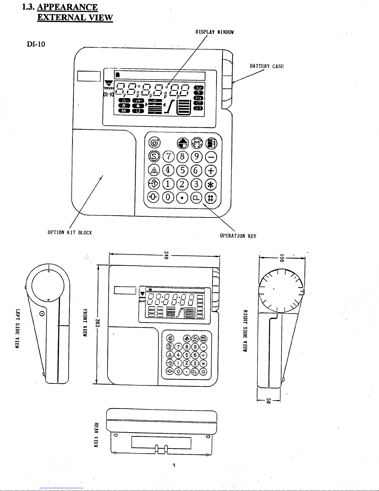
1.2. APPEARANCE 3
1.3. DISPLAY & KEYS 4
1.4. INDICATOR LAMPS 5
2.0. INSTALLATION 6-9
2.1. UNPACKING 6
2.2. INSPECTING 6
2.3. REPACKAGING 6
2.4. UNLOCKING (DIGI GRAND) 6-8
2.5. DI-10 POLE ASSEMBLY 9
3.0. SPECIFICATIONS 10-15
3.1. CAPACITIES 10
3.2. TECHNICAL 11
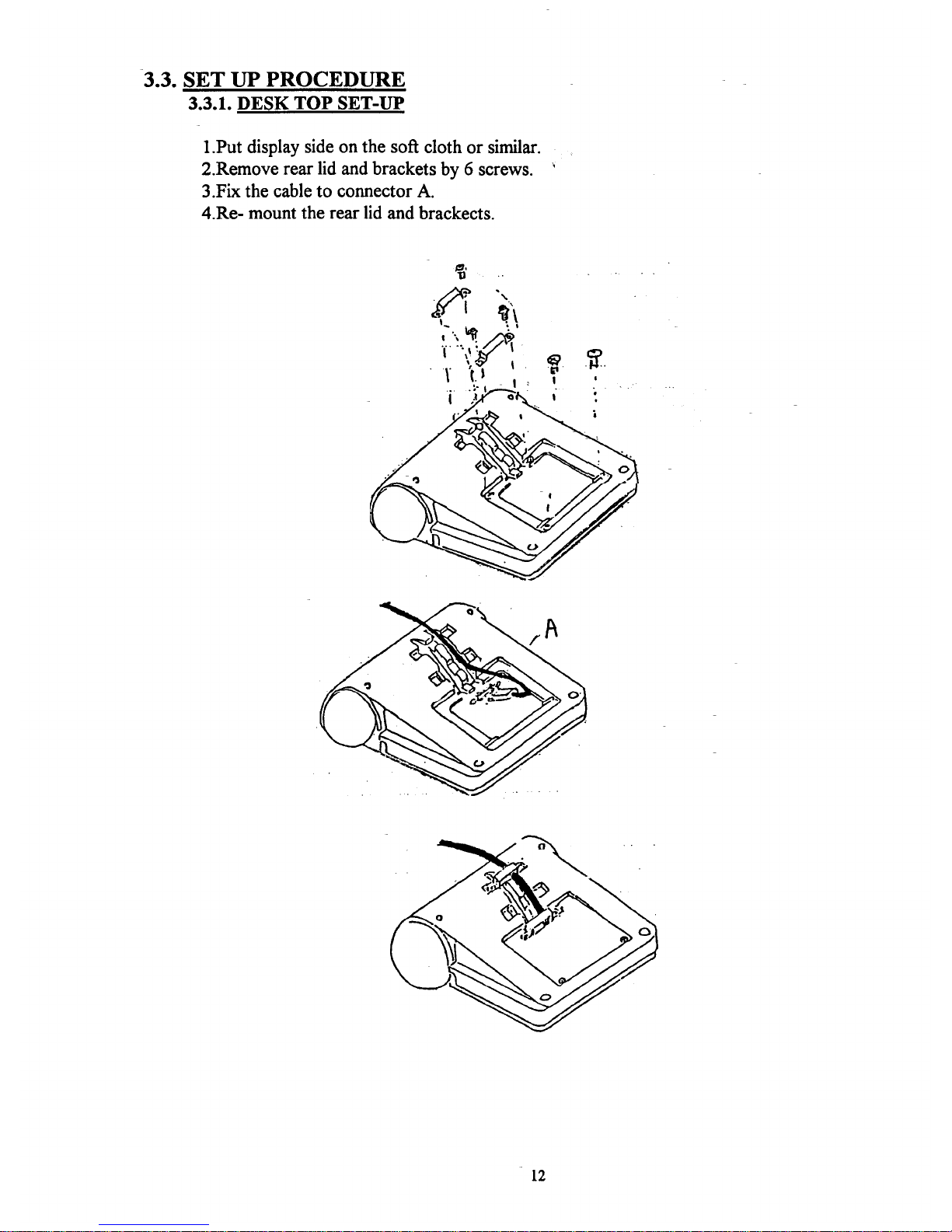
3.3. SET-UP PROCEDURE 12-13
3.4. FEATURES 14-15
4.0. OPERATION INSTRUCTION. 16-24
4.1. POWER ON 16
4.2. ONE TOUCH TARE 17
4.3. DIGITAL TARE 18
4.4. DIGITAL TARE WHILE WEIGHING 19
4.5. SET POINTS 20-21
4.6. ADDITION AND SUBTRACTION 22
4.7. COUNTING. 23
4.8. NET/GROSS DISPLAY 23
4.9. DATE & TIME SETTING 24
4.10. LB/KG CONVERSION 24
5.0. DI-10 OPTIONAL EQUIPMENT 25-30
5.1. PRINTER 25
5.2. SETPOINT OUTPUT. 26-27
5.3. RS-232C DATA OUT 28-30
5.4. AC/DC ADAPTOR. 30
6.0. MAINTENANCE, CALIBRATION, TEST PROCEDURE & SERVICE 31-39
6.1. MAINTENANCE PROCEDURES 31-32
6.2. SERVICE & REPAIR 32
6.3. PLATFORM WIRING 32
6.4. ERROR MESSAGE LIST 33
6.5. SPEC. LIST 34-36
6.6. CALIBRATION 37-38
NOTES: 39
1
Page 3

DI-10 OPERATING MANUAL
1.0. GENERAL
1.1. DESCRIPTION
The DI-10 Indicator offers a practical solution to a wide range of weighing applications.
There are a variety of weight capacities and increments available. The display resolution
is selectable from 1/3000 to 1/10000. It features keyboard calibration with auto-span.
Operates on 6 “C” cell batteries or with its AC/DC adapter. The DI-10 is able to support
single load cells that have an output range of 0.4mV/V to 4.0mV/V. The DI-10 is able to
support up to 4 load cells when used with the AC/DC adapter. This indicator features
LCD graphic display, 5 weighing modes, optional devices such as RS-232, Set Point
Output, and a built in Printer. For a list of platforms sizes and available above mentioned
capacities see page 2.
This instruction manual will provide the user with all the information necessary to
understand, set-up and operate the DI-10 scale. Included in this manual are descriptions,
specifications, drawings, and operating instructions.
2
Page 4
Page 5
Page 6
Page 7

2.0. INSTALLATION
This section provides the information required for installation of the DI-10 weight indicator.
The following steps accomplish installation.
1. Unpacking
2. Set-up Procedure
2.1. Unpacking
Each component of the DI-10 is packed in a specially designed carton. Remove each
component from its carton, separate the component from its polystyrene shell assembly
and set aside. Inspect the carton interior to be sure that all accessories have been
removed from the carton. Inspect the carton inner panels for accessories.
NOTE:
Be sure to repack all materials within the carton set. Store the cartons in a
secure area so they can be available whenever shipment of the scale is required.
2.2. Inspection
Immediately after unpacking, a visual inspection of the instrument should be performed.
If any damage has been incurred during transportation the shipper and DIGI MATEX
INC. should be notified immediately. Instructions for assessment of damage and further
procedures will then be determined.
2.3. Repackaging
If, at anytime, the DI-10 weight indicator must be returned for modification, calibration,
or repair, be sure that it is properly packed with sufficient cushioning materials.
Whenever possible, the original carton assembly should be retained for this purpose.
Any damage caused by improper packaging will not be covered by warranty.
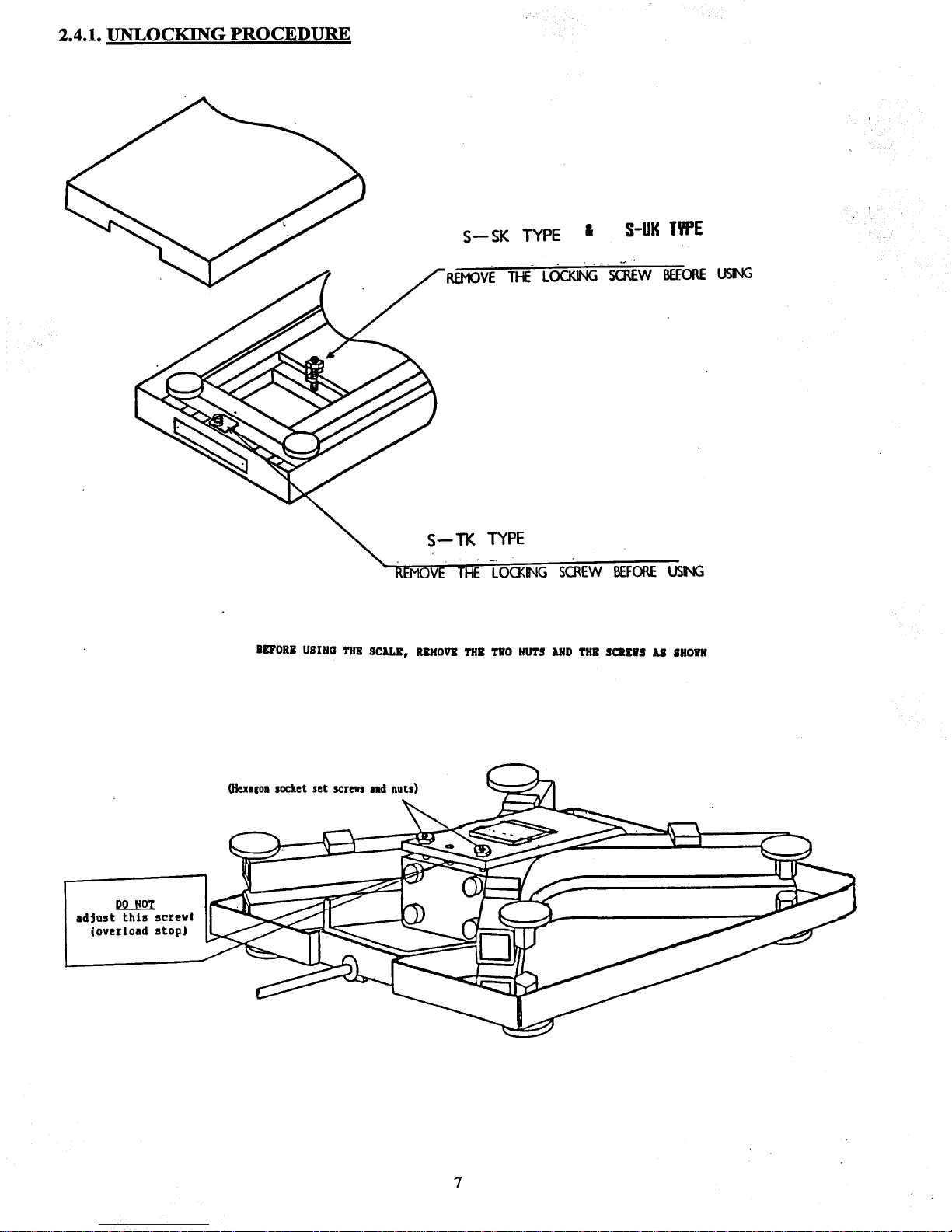
2.4. Platform Unlocking Procedure
The unlocking procedure is different for each style of platform and are included on
the following pages.
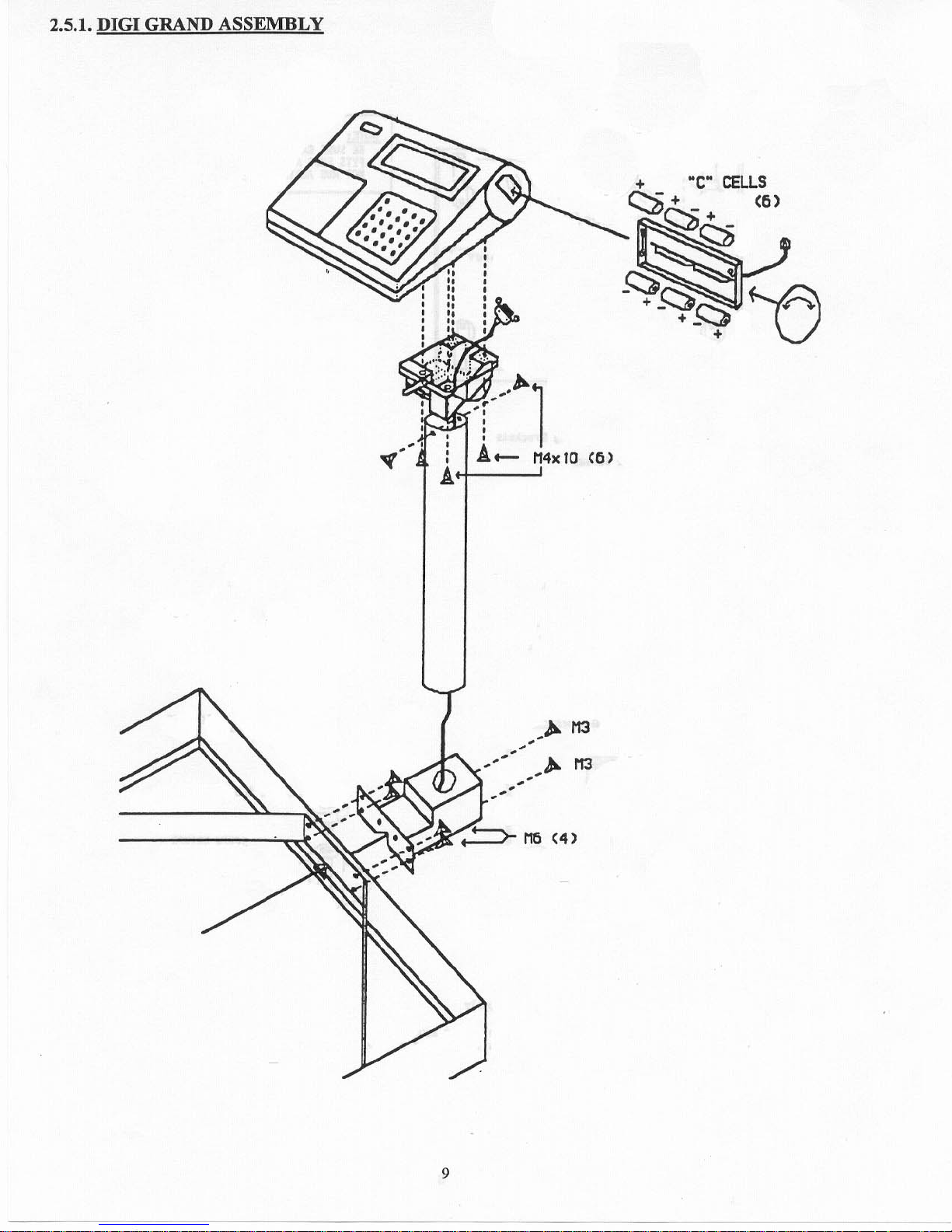
2.5. Digi Grand Pole Assembly
The optional pole mounting kit comes with all the necessary hardware and assembly
is easy. See page 9 for details.
6
Page 8
Page 9

Page 10
Page 11
3.0. SPECIFICATION
3.1. PLATFORMS
The following is a list of platforms :
Model Platform
Size/Platter
Capacities
S-AL bench 12” x 14” x3” 1 LB. 5 LB. 10 LB. 25 LB. 50 LB.
S-SL bench / floor 13” x 17” 60 LB. 150 LB. 300 LB.
S-TL floor 17” x 21” 150 LB. 300 LB. 500 LB. 1000 LB.
S-UL floor 24” x 28” 150 LB. 300 LB. 500 LB. 1000 LB.
S-PL floor 30” x 30”
1000 lb. to 3000 lb.
36” x 36”
S-PL floor 48” x 48”
48” x 72”
60” x 60”
2500 lb.
to
25000 lb.
60” x 84”
Ramps , Other Capacities And Stainless Steel Platforms Also Available
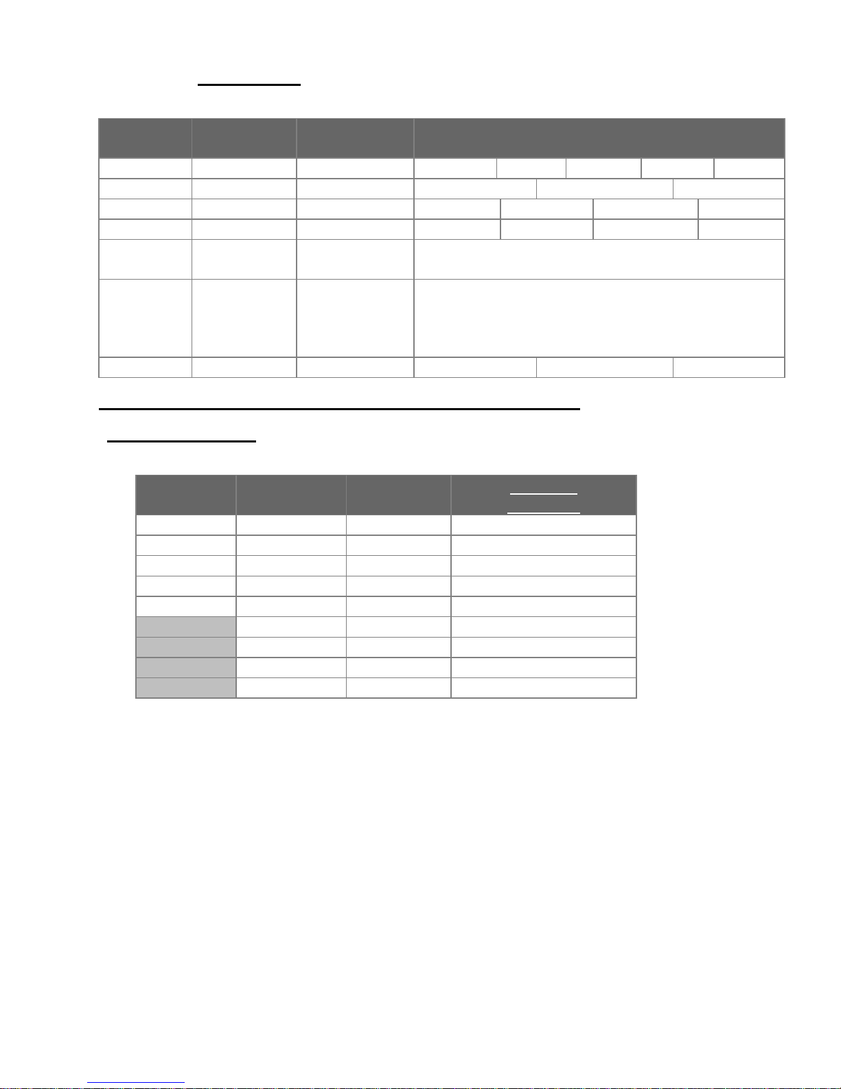
Choosing A Capacity : Multiply the Decimal Location by the Minimum Weight by the Display
Resolution (=) Capacity
Decimal
Location
Minimum
Weight
Display
Resolution
Available
Capacities
0.0000 1 1 / 2000 1lb,2.5lb,3lb.,5lb.,6lb,.
0.000 2 1 / 2500 10lb.,25lb.,30lb.,50lb.,
0.00 5 1 / 3000 60lb.,75lb.,100lb.,125lb
0.0 10 1 / 5000 150lb.,200lb.,250lb.,
0 20 1 / 6000 300lb.,375lb.,500lb.,
50 1 / 7500 600lb.,750lb.,1000lb.,
100 1/10000 1500lb.,2000lb.,2500lb.
200 1/12500 3000lb.,3750lb.,5000lb.
500 1/15000 6000lb.,7500lb.,10000lb
Example: dec. loc. ‘TIMES’ min. wt. ‘TIMES’ disp. res. = avail cap.
0.00 ‘TIMES’ 5 ‘TIMES’ 1 / 7500 = 375. 00 lb.
* Units can be programmed to primarily weigh in lb., oz., kg., g., or dwt.
10
Page 12
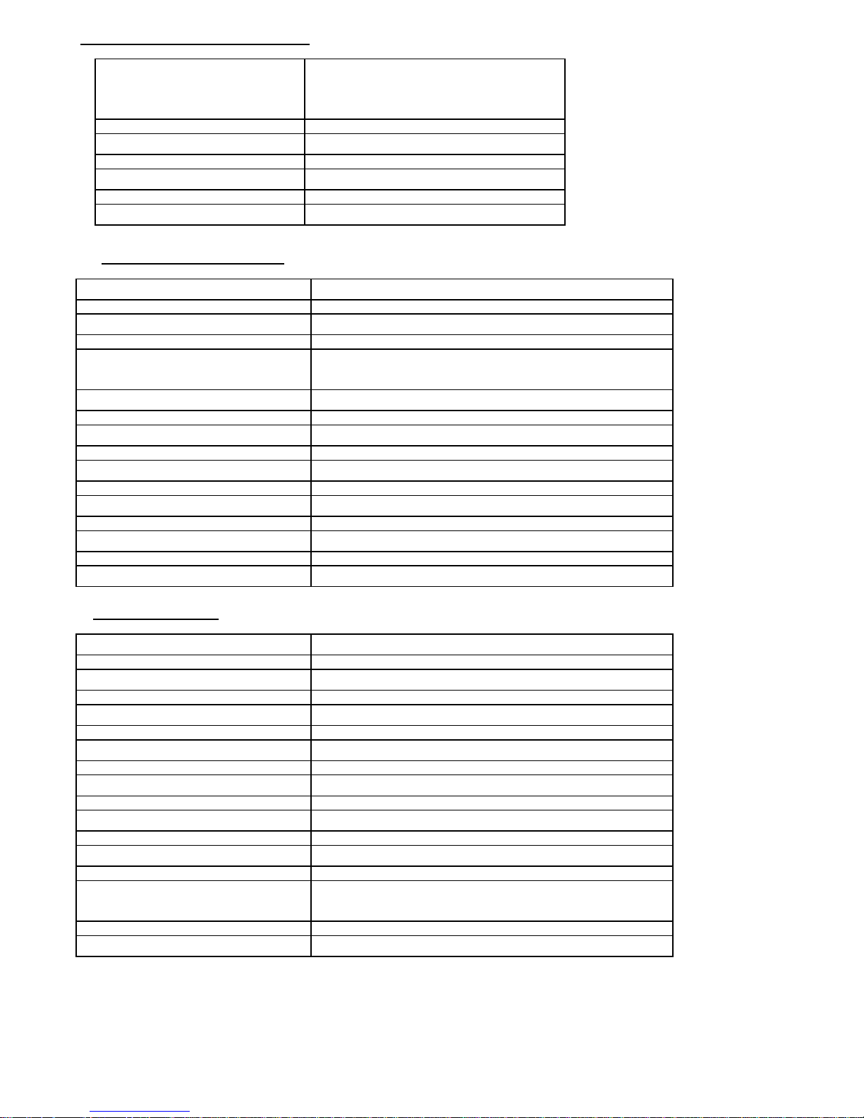
3.2. TECHNICAL (MODEL SPEC)
* Power source * D.C 12V 0.5A (AC/DC adaptor)
* D.C 1.5V x 6 pcs. (“C” cell)
(“C” cell can't operate printer)
* Operating temperature * -10 ... +40EC
* Operating humidity * 15 ... 85% RH.(Non-condensing)
* Power consumption * 1 w/h.
ANALOG SPEC. (DI-10)
* Input sensitivity * 0.25 :V/div. to 20 :V/div.
* Zero adj. range * 1 mV
* Temp. characteristic * ZERO"(0.2:V " 6ppm of ZERO)/EC
SPAN ..." 6 ppm/EC
* Speed of A/D conversion: * 10 times/sec.
* Non linearity * 0.016 % of F.S or less
* L/C to be used * 0.4 mV/V to 4 mV/V
* L/C excitation voltage * DC 5V.
* Number of the scale * 1 (one) scale
* Display resolution * up to 1/10000
DISPLAY SPEC.
* Display * 6 digits.
* Tare * 6 digits
* Setpoint 1 (LO) * 6 digits.
* Setpoint 2 (OK) * 6 digits.
* Setpoint 3 (HI) * 6 digits
* Weighing unit * 5 kinds "g","kg","lbs","oz","dwt".
* Counting unit * 1 kind "pcs"
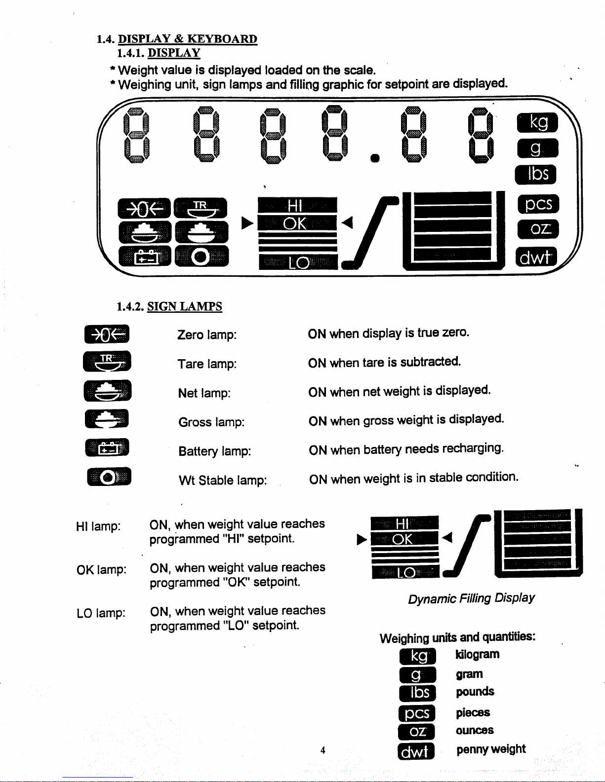
* Sign lamps * 9 kinds "ZERO","TARE","NET","GROSS
"BATT","W.S","HI","OK","LO".
* Filling graphic * 2 kinds rough and fine
11
Page 13
Page 14

Page 15

3.4. FEATURES
1. Super Large LCD And
Dynamic Filling In Graphic
Display.
* 25.4 mm figure height.
* 2 kinds of filling in graphic, rough and fine.(selectable)
* 9 kinds of weighing sign and 5 kinds of weighing unit.
2. Battery Drive Available. * D.C 1.5 V x 6 pcs.(AM-2)
* In The Case Of Battery Drive, Printer Option And 4 Load
Cell Construction Scale Is Not Available
* Alkaline cell is better than another material.
3. Automatic Power
Off.(Selectable Time Off)
* To save power specially in the case of battery drive,
automatic power off function is provided
4. Up To 4 - 350Ω Load Cells
Can Be Driven with a (DI-10)
* This is available only in the case AC/DC adaptor is used as
power supply. (Only One Load Cell Can Be Driven In The
Case Of Battery Operation.)
* DIGI's S-S,S-T,S-U are recommendable as external scale.
5. Five Kinds Of Weighing
* In "kg","g","lbs","oz" or "dwt" mode.
Mode.(Selectable)
6. Weighing
Conversion.(Selectable)
* "kg" to "lb." and vise-versa. (1 lb = 0.45359 kg,
1 kg = 2.2046 lb. )
* "g" to "oz" or "dwt" and vise-versa. (1 g = 0.03527 oz,
1 oz = 20 dwt.)
7. Three Kinds Of Taring
* One touch tare, Digital tare, Digital tare during weighing.
Method.(Selectable)
8. Addition & Subtraction. * Max. 6 digits and an alarm sign "Add OFF" and "SUb OFF"
are provided when they exceed the limit.
9. NET/GROSS Conversion. * Individual indicator for NET and GROSS.
10. Automatic Zero Tracking. * To eliminate small weight display drifting.
11. Automatic Print.(Selectable) * To print out weighing result automatically
12. Automatic Calibration.
13. Data Output By RS-232C For
* For data transfer to external device
External Device. (Option)
14
Page 16

FEATURES (continued)
14. Setpoint Data Output.
* To drive external device.
(Option)
15. Built In Printer. (Option) * To print out weighing result.
In The Case Of Battery Drive, Printer Option Is Not Available
16. Code No. Printing. * To specify the printed out weighing result.
17. Date & Time Printing. * To specify the printed out weighing result.
* Built in clock.(no back up after power disconnect)
18. Counting Function. * For parts counting operation.
* Print out, addition and subtraction are not possible.
19. Programmable Scale Capacity
And Scale Interval.
* Minimum graduation (increment),1,2,5,10,20 and 50 are
available.
* Display resolution up to 1/10.000 is available.
20. Meets Or Exceeds The
1/3000 display resolution.
Requirements Of OIML Class 3
21. Articulated Head Mount for
*At an angle of 80 °.
Pole Mount
15
Page 17

Page 18

Page 19

Page 20

Page 21

Page 22

Page 23

Page 24

Page 25

Page 26

Page 27

Page 28

Page 29

Page 30

Page 31

5.3. RS-232 (continued)
2. Communication Control Command.
DC1 (11H) : Data request from DI-10.
DC3 (13H) : Communication break request.
(DI-10 receives “DC3”, the time out will be extended to 5 sec.
ACK (06H) : Positive response.
NAK (15H) : Negative response.
EOT (04H) : Communication end.
3. Text Code
* Data Code
0 (30H) Represents NET WEIGHT.
3 (33H) Represents CODE NO.
4 (34H) Represents TARE
A (41H) Represents GROSS WEIGHT
* Data
− (2DH) : Represents minus. (plus=0 )
• (2EH) : Represents decimal point.
* Terminal Code
CR (0DH) : Represents data terminate code.
LF (0AH) : Represents text end code.
4. Location Of Connector And Pin Assignment.
pin 1 SP-1 (LO)
pin 2 COM (GND)
pin 3 SP-2 (OK)
pin 4 RXD
pin 5 TXD
pin 6 CTS
pin 7 RTS
pin 8 SP-3 (HI)
*SP-1,SP-2 AND SP-3 ARE SETPOINT OUTPUT with 5V
5.4. AC / DC ADAPTER
The specifications for the AC/DC adapter are as follows:
* Input voltage to your needs
* Output volyage 12V
* Output current 1.0 A (minimun)
* Type of connector see below
Center Electrode Is Negative (−)
Outer Electrode Is Positive (+)
D 1 D 2 L
5.5 mm 2.1 mm 9.5 mm
30
Page 32

6.0. MAINTENANCE, CALIBRATION, TEST PROCEDURE & SERVICE
This section contains information and instructions concerning maintenance of the DI-10
weighing Scale.
Preventive maintenance consists of periodically cleaning the external surfaces of the instrument
and should be performed as often as operating conditions warrant.
The calibration procedure is designed to be an aid in maintaining the scale accuracy within
specifications. The calibration procedure may also serve as a performance test procedure.
CAUTION: DO NOT ATTEMPT ANY SERVICE WHILE THE INSTRUMENT
IS CONNECTED TO THE POWER LINES.
6.1. MAINTENANCE PROCEDURES
6.1.1. EXTERIOR MAINTENANCE
The exterior surfaces of the counting scale can be easily cleaned using soap and
water. However, extreme caution should be used so that there is no possibility of
water penetration into the scale electrical or mechanical sections. A damp cloth or
sponge is suggested. NEVER USE ACETONE, MEK, OR SIMILAR
SOLVENTS ON THE PLASTIC HOUSING AS THEY WILL ETCH THESE
SURFACES.
For grease or other difficult spots, a chlorothane or naptha based cleaner may be
used. Never use any solvents on the front or rear panels.
Accumulations of dust or direct particles between the pins of the connectors may
be removed by using dry forced air or a small dry brush.
6.1.2. INTERNAL MAINTENANCE
Internal maintenance is not normally required and if it is, should not be attempted
except by a qualified, authorized service technician.
31
Page 33

Page 34

6.4. ERROR MESSAGE LIST
The following error messages will appear when an incorrect operation is taken :
Add OF Whwn accumulated weight total exceeds 6 digits.
When quantity displayed exceeds 6 digits.
OF When displayed weight exceeds scale capacity.
Spn Er When weight value entered during calibration
procedure is not in proper range .
− − − − − −
When zero calibration is not correct during calibration
procedure.
Please try Zero and Span calibration.
8 8 8 8 8 8 When zero calibration is not correct when in weighing
mode.
Please try Zero and Span calibration
Add X X When sample weight is an insufficient sample size.
Please place X X more pcs on scale press [PCS] key
SP Err
When an incorrect setpoint value is entered ↓ (Err)
(ex.SP1 = 2.00[LO] SP2 = 4.00[OK] SP3= 0.00[HI] )
Sub UF When total weight is minus.
F F F F F F When quantity result exceeds 6 digits.
33
Page 35

Page 36

6.5.2 SPEC. LIST
Function Table Of 141
SPEC #
Bit 3 Bit 2 Bit 1 Bit 0
& standard setting
Spec 00
0 0 0 0
Spec 01
0 0 0 0
Spec 02
0 0 0 0
not used Setpoint Function
0 = yes
1 = no
Key-In Wt. Print
0 = yes
1 = no
Print out by ∗ key
when “0” weight
0 = no
1 = yes
Date & Time Print
0 = no
1 = yes
Net/Gross
Display Change
0 = yes
1 = no
Negative Wt. Acc.
0 = yes
1 = no
Data Output Serial I / F
Weighing Unit
Change
0 = yes
1 = no
Spec 03 -Spec 06 not used
Spec 07
0 0 1 0
Spec 08
1 1 0 0
Setpoint Out &
Display
0 = only + weight
1 = only − weight
Print Code #
0 = no
1 = yes
Setpoint Out &
Display
0 = absolute value
1 = sign selectable
Filling Display
0 = no
1 = yes
Date Order
00 = yy.mm.dd
01 = dd.mm.yy
10 = mm.dd.yy
Insufficient Sample Range
00 = 0.1 % of scale capacity
01 = 0.2 % of scale capacity
10 = 0.3 % of scale capacity
11 = 0.4 % of scale capacity
Spec09 Automatic Power OFF Timer
1 0 1 0
0 0 0 0 = none
0 0 0 1 = 1 min.
0 0 1 0 = 2 min
0 0 1 1 = 3 min
0 1 0 0 = 4 min
0 1 0 1 = 5 min
0 1 1 0 = 6 min
0 1 1 1 = 7 min
1 0 0 0 = 8 min
1 0 0 1 = 9 min
1 0 1 0 = 10 min
1 0 1 1 = 11 min
Note : Wt = Weight
∗ key = Print key
Specifications in bold print were newly added from Ver 3.00
Specifications from Spec.03 to 06 are deleted from Ver. 3.00
Printer Connection
0 = no
1 = yes
0 = no
1 = yes
Automatic Print
0 = no
1 = yes
yy = year
mm = month
dd = day
1 1 0 0 = 12 min
1 1 0 1 = 13 min
1 1 1 0 = 14 min
1 1 1 1 = 15 min
35
Page 37

6.5.3 SPEC.LIST (continued)
Function Table Of 142
SPEC #
Bit 3 Bit 2 Bit 1 Bit 0
& standard setting
Spec 13
0 0 0 0
Spec 14
0 0 0 0
Spec 15
0 0 0 0
Spec 16
0 0 0 0
Spec 17
0 0 0 0
Spec 18
0 0 0 0
Zero Tracking
During Tare
Reduction
0 = yes
1 = no
Manual Tare
Clear
0 = yes
1 = no
NTEP
0 = no
1 = yes
Auto Tare
Clear
0 = no
1 = yes
Decimal Point
0 = period
1 = comma
Zero
Suppress
Code # Print
0 = no
1 = yes
Re-Zero Key
During Tare
Reduction
0 = yes
1 = no
Tare Decrease
0 = yes
1 = no
When Net Weight
is Below “0”
0 = minus
1 = blank
A.T.C. condition
0 = net 21d
1 = net 1d
Non-Stable
Output
0 = no
1 = yes
Add Function
When Auto
Print
0 = no
1 = yes
Scale Start Range
0 = 10 % of cap
1 = 5 % of cap
Tare Increase
0 = yes
1 = no
When Gross Weight
Is Below “0”
0 = minus
1 = blank
Digital Tare
0 = yes
1 = no
Negative Total
0 = yes
1 = no
Scale Start
0 = auto
1 = by RE-ZERO
Spec 19 Senseitivity Of Load Cell To Be Used
1 0 0 1
0 0 0 0 = 3.46 − 4.00mV/V
0 0 0 1 = 3.00 − 3.46mV/V
0 0 1 0 = 2.59 − 3.00mV/V
0 0 1 1 = 2.55 − 2.59mV/V
0 1 0 0 = 1.95 − 2.55mV/V
0 1 0 1 = 1.69 − 1.95mV/V
0 1 1 0 = 1.46 − 1.69mV/V
0 1 1 1 = 1.27 − 1.46mV/V
1 0 0 0 = 1.09 − 1.27mV/V
1 0 0 1 = 0.95 − 1.09mV/V
1 0 1 0 = 0.82 − 0.95mV/V
1 0 1 1 = 0.71 − 0.82mV/V
1 1 0 0 = 0.61 − 0.71mV/V
1 1 0 1 = 0.53 − 0.61mV/V
1 1 1 0 = 0.46 − 0.53mV/V
1 1 1 1 = 0.40 − 0.46mV/V
NOTE: IR. = Internal Count.
FS. = Full Scale.
Cap. = Scale Capacity.
Specifications in bold print were newly added from Ver. 3.00
Specifications from spec. 10 to 12 were deleted from Ver. 3.00
Weighing Unit
(Display/Print)
0 = yes
1 = no
Tare Limit
0 = 100 % of FS.
1 = 5 % of FS.
Zero Lamp Range
0 = gross 0 ±1/4d
1 = net 0 ±1/4d
Print Limit
0 = below 0 d
1 = below 20 d
Double Print
0 = yes
1 = no
Tare Exchange
0 = yes
1 = no
36
Page 38

Page 39

Page 40

NOTES:
39
Page 41

DI-10 Limited Warranty
Rice Lake Weighing Systems (RLWS) warrants that all RLWS equipment and systems properly installed by a
Distributor or Original Equipment Manufacturer (OEM) will operate per written specifications as confirmed
by the Distributor/OEM and accepted by RLWS. All systems and components are warranted against defects
in materials and workmanship for one (1) year.
RLWS warrants that the equipment sold hereunder will conform to the current written specifications
authorized by RLWS. RLWS warrants the equipment against faulty workmanship and defective materials. If
any equipment fails to conform to these warranties, RLWS will, at its option, repair or replace such goods
returned within the warranty period subject to the following conditions:
• Upon discovery by Buyer of such nonconformity, RLWS will be given prompt written notice with a detailed explanation
of the alleged deficiencies.
• Individual electronic components returned to RLWS for warranty purposes must be packaged to prevent electrostatic
discharge (ESD) damage in shipment. Packaging requirements are listed in a publication, “Protecting Your Components
From Static Damage in Shipment,” available from RLWS Equipment Return Department.
• Examination of such equipment by RLWS confirms that the nonconformity actually exists, and was not caused by
accident, misuse, neglect, alteration, improper installation, improper repair or improper testing; RLWS shall be the sole
judge of all alleged non-conformities.
• Such equipment has not been modified, altered, or changed by any person other than RLWS or its duly authorized repair
agents.
• RLWS will have a reasonable time to repair or replace the defective equipment. Buyer is responsible for shipping charges
both ways.
• In no event will RLWS be responsible for travel time or on-location repairs, including assembly or disassembly of
equipment, nor will RLWS be liable for the cost of any repairs made by others.
THESE WARRANTIES EXCLUDE ALL OTHER WARRANTIES, EXPRESSED OR IMPLIED,
INCLUDING WITHOUT LIMITATION WARRANTIES OF MERCHANTABILITY OR FITNESS
FOR A PARTICULAR PURPOSE. NEITHER RLWS NOR DISTRIBUTOR WILL, IN ANY EVENT,
BE LIABLE FOR INCIDENTAL OR CONSEQUENTIAL DAMAGES.
RLWS AND BUYER AGREE THAT RLWS’S SOLE AND EXCLUSIVE LIABILITY HEREUNDER
IS LIMITED TO REPAIR OR REPLACEMENT OF SUCH GOODS. IN ACCEPTING THIS
WARRANTY, THE BUYER WAIVES ANY AND ALL OTHER CLAIMS TO WARRANTY.
SHOULD THE SELLER BE OTHER THAN RLWS, THE BUYER AGREES TO LOOK ONLY TO
THE SELLER FOR WARRANTY CLAIMS.
No terms, conditions, understanding, or agreements purporting to modify the terms of this warranty shall have any legal effect unless
made in writing and signed by a corporate officer of RLWS and the Buyer.
© 2002 Rice Lake Weighing Systems, Inc. Rice Lake, WI USA. All Rights Reserved.
RICE LAKE WEIGHING SYSTEMS
• 230 WEST COLEMAN STREET • RICE LAKE, WISCONSIN 54868 • USA
 Loading...