

Page 1

OPERATION MANUAL
Model : DC-150
Edition
Month Year
3rd August 1996
TERAOKA SEIKO CO., LTD.
13-12 Kugahara 5-chome, Ohta-ku
Tokyo 146 Japan
TEL: +81-3-3752-2131
FAX: +81-3-3752-2801
Page 2

1. SET UP
1
Page 3

1.2 OVERALL VIEW------------------------------------------------5
1.2a Name Of Each Parts-------------------------------------------------------------5
1.2b Display & Keys--------------------------------------------------------------------6
1.3 LABEL FORMAT AND LABEL SET UP ---------------10
1.3a Specification of Labels and Receipt --------------------------------------- 10
1.3b Standard Print Formats ------------------------------------------------------- 10
1.3c How to set paper--------------------------------------------------------------- 11
1.4 OPERATION FLOW CHART-----------------------------12
2
Page 4
1.1 Specifications
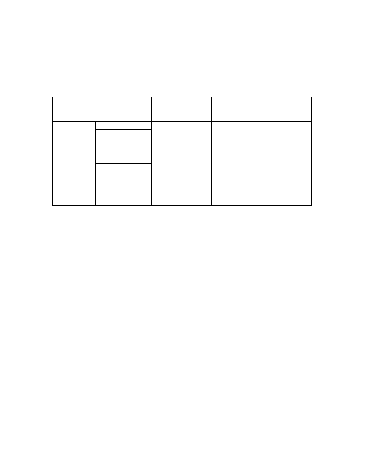
1 MODEL VARIATION
Model
Built-in scale I/F for External
Scale
Optional I/F for
peripherals
#1 #2 FB
DC-151S
DC-151S-64KB 500g,1kg, 2.5kg, 5kg
NO NO
DC-151S-518KB 10kg, 25kg, 50kg
DC-153SI
DC-153SI-64KB (1lb, 2.5lb, 5lb, 10lb
{ { {
YES
DC-153SI-518KB 25lb, 50lb 100lb)
DC-152D
DC-152D-64KB 500g/2.5kg,500g/5kg
NO NO
DC-152D-518KB 1kg/5kg, 1kg/10kg
DC-153DI
DC-153DI-63KB (1lb/5lb, 1lb/10lb,
{
X
{
YES
DC-153DI-518KB 2.5lb/10lb,2.5lb/25lb)
DC-152CFX
DC-152CI-64KB no scale
{ { {
YES
DC-152CI-518KB
2 SCALE SPECIFICATIONS
* WEIGHING DEVICE : LOAD CELL
* DISPLAY DEVICE : Fluorescent Display
* INTERNAL RESOLUTION : 1/500,000
* DISPLAY RESOLUTION : 1/10,000 or 1/5,000 or 1/2,500
3 MEMORY SPECIFICATIONS
* 64kb (STANDARD) for 385 ITEM MEMORY.
* 512kb (Expand Version) for 3,080 ITEM MEMORY.
3
Page 5

4 INTERFACE
* INTERFACES FOR PERIPHERALS
INTERFACE PURPOSE REMARKS
RS-232C-1(8PIN) MODEM, FL-1 STANDARD
TTL SERIAL I/F (8PIN) or RS-232C-2 (8PIN) BAR-CODE SCANNER
TTL OUTPUT (8PIN) or RS-422 (8PIN) SET POINT OUTPUT OPTION
KEY BOARD I/F IBM-AT COMPATIBLE
KEYBOARD
* EXTERNAL SCALE INTERFACES
INTERFACE
RS-232C FOR FORCE BALANCE
EXTERNAL SCALE INTERFACE (SCALE 1)
EXTERNAL SCALE INTERFACE (SCALE 2)
5 DISPLAY SPECIFICATION
* 20 DIGITS ( 5 X 7 DOTS) Fluorescent Display
* WEIGHT : 6 DIGITS
* UNIT WEIGHT : 5 DIGITS
* QUANTITY : 6 DIGITS
6 PRINTER
* THERMAL PRINT
* 0.135 mm x 0.135 mm (Square Dot)
* 448 Dots / Line
7 ELECTRICAL REQUIREMENT
* OPERATION VOLTAGE : 100, 117, 220, 230, 240 Vac
* OPERATING FREQUENCY : 50 or 60Hz
* POWER CONSUMPTION : 15Wz
8 ENVIRONMENT
* OPERATING TEMPERATURE : 0 ~ 40C ( -4F ~ 104F)
* OPERATING HUMIDITY : 15% TO 85%RH
9 DIMENSION
* OVERALL WIDTH x HEIGHT x DEPTH : 410(W) x 498 (D) x 158 (H) mm
16.14(W) x 16.06 (D) x 6.2 (H) inches
* TOTAL WEIGHT : 11.2kg (124.lb.)
4
Page 6

1.2 Overall View
1.2a Name Of Each Parts
1. MAIN SWITCH 7. PORT PANEL A. MODEM /FL-1
2. SCALE 1 B. SET POINT OUTPUT
3. SCALE 2 C. PEN /REWAIND SCANNER
4. DISPLAY WINDOW D. IBM KEY BOARD
5. OPERATION KEYS E. FORCE BALANCE
6. PRINTER F. EXTERNAL SCALE I/F -1
G. EXTERNAL SCALE I/F -2
5
Page 7
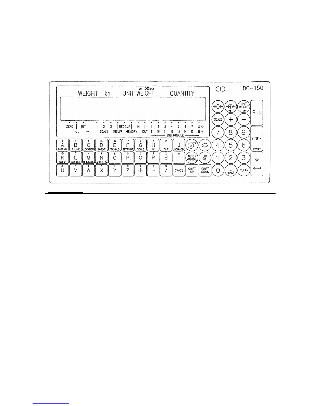
1.2b Display & Keys
INDICATORS
INDICATORS MEANINGS
ZERO Weight is zero
STABLE Weight is stable
NET Presence of a tare weight
kg Scale weighing in kg base. (available in lb. version only)
SCALE 1~3 Scale is in use
INSUFF Sample size is too small to calculate
RECOMP. Unit weight may be recalculated by pressing PIECES key.
MEMORY An accumulated total is in memory
IN Quantities being added to inventory and movement data
OUT Quantities being removed to inventory and movement data
JOB NODULE 1~8 JOB instruction is in the process of Auto job operation
(9~16) (9~16 will flash on and off)
6
Page 8

FUNCTION OF KEYS
0 ~ 9 NUMERIC KEYS
Key numerical values into the system.
•
I N/OUT
DECIMAL POINT
Enter decimal point when entering data
Toggle between receiving, shipping, Non-add operation together with
[SHIT DOWN] key in operation mode.
CLEAR
CLEAR
Clear keyed-in data from display.
Delete the data in memory file.
Æ
FEED
Feed paper.
MODE
MODE
Toggle between modes.
Exit modes without saving data.
AUTO
MANUAL
AUTO / MANUAL
Toggle between Auto Job Operation and Manual Operation in Operation mode.
Back to the precious screen in programming data.
LOT
NO.
LOT NUMBER
Enter the key-in data to LOT No. in OPR mode.
RE ZERO
RE-ZERO
Eliminate weight from the weight dispaly with no tare and causes it to show a true
zero.
TARE
←
TARE
Enter a tare value into the system.
Toggle the data files to program or access
Move the triangle cursor to Right.
7
Page 9

UNIT
WEIG HT
→
UNIT WEIGHT
Enter weight per 1000 count of pieces.
Toggle the data files to program or access.
Move the triangle cursor to Left.
SCALE
SCALE
Toggle between the scales, if the system is with pural scales.
+
PLUS
Weight data addition and print out.
In Maintenance mode, advantage to the next choice, when the triangle cursour is
blinking.
_
MINUS
Weight data subtraction and print out.
In Maintenance mode, moves back to the previous choice, when the triangle
cursour is blinking.
PIECES
PIECES
Sample entry in counting mode to accumulate UNIT WEIGHT.
CODE
RETRY
CODE
Call ITEM data from memory file.
Reprint the same label without saving inventory total in OPR. mode.
Print TEST LABEL (TOTAL LABEL) in programming FREE FORMAT.
ENTER
ENTER
Print total accumulation in OPR. mode.
Enter set up choices and advantages to next choice. Then, at the end of
choices,store the data into memory files.
A ~ Z
+ , − , /
ALPHABET / PLUS / PLUS / MINUS / SLASH
Key alphabetical data into the system.
Assign the data to ITEM FILES together with [SHIFT DOWN] key.
NOTE * [Y] key is used for executing the deletion in the deletion screen.
* [N] key is used for escaping the deletion screen.
* [M] key is used for test printing (gross label) in free format setting.
8
Page 10

SPACE
lb/kg
SPACE
Enter SPACE in alphabetical data entry.
Toggle the display between pound (lb) and kirogram (kg). This function is available
in LB version.
Print TEST LABEL (ITEM LABEL) in programming FREE FORMAT
SHIFT
DOWN
SHIFT DOWN
Change the key functions to the lower line of Alphabet keys.
SHIFT
UP
SHIFT UP
Change the key functions to the special charactors in the upper line of Alphabet
keys.
9
Page 11

1.3 Label format and label set up
1.3a Specification of Labels and Receipt
Outer diameter : 105mm
Inner diameter : 40mm
Width of Receipt Roll : 40mm or 66 mm
Width of label roll : 42mm or 66 mm
1.3b Standard Print Formats
DC-150 has 7 standard label formats and the memory area for 2 free label formats. The
format can be selected in PRINT SPEC in maintenance mode.
Also, 3 types of labels can be printed by the following applications in operation mode.
ITEM LABEL ...... Issued in single operation in OPERATION MODE
TOTAL LABEL ...... Issued in multiple operation in OPERATION MODE
GROSS LABEL ...... Issued in gross weight operation in OPERATION MODE
NOTE) Refer to APPENDIX Ι to see the sample of standard format.
10
Page 12

1.3c How to set paper
1. Remove front panel of printer.
2. Open thermal head by pulling down the lever.
3. Open the side panel in right side of printer block.
4. Slide out label cassette from the main unit.
5. Twist the roll holder s 45 degree to clockwise and pull it out.
6. Take out the empty roll core and place a new stock roll.
7. In case of label, take several labels from the end of the label stock and run it above
the guides o
and through dispenser p and set back paper on take up reel q with
paper clampr.
8. Push roll holder s
to set reeln with the same direction as drawing, until it stops.
9. Set the label and receipt switch on the left side of label cassette.
[LEFT (label) ↔ RIGHT(receipt)]
10.Slide label cassette back into the main unit, along with the metal shaft under the
thermal head block.
11.Close the thermal head by pushing the top of thermal head.
12.Close the side panel and put the front panel of printer back.
13.Depress [FEED] Key to have paper tension.
14. In case of receipt, set receipt roll as the same as label stock
15. Fold the end of the receipt roll and hook the fold on dispenser p
as drawing A.
16. Set the cassette into the main unit and close the thermal head as the same as label.
17. Depress [FEED] key.
DRAWING
11
Page 13

1.4 Operation Flow Chart
OPERATION MODE Receiving Operation (Manual / Auto Job Operation)
Shipping Operation (Manual / Auto Job Operation)
Non-add Operation (Manual / Auto Job Operation)
PROGRAM MODE I.D. Code Setting
Date / Time Setting
Set Point Setting
Title Contents Setting (No.1 ~ No.16)
Preprinting Setting (No.1 ~ No..3)
Format Copy
Free Format Setting (Max. 2 Format)
Shelf Location Format Setting
Shelf Location Limit Setting
Address Setting
CHECK MODE Memory Contents Check
Inventory Data Check
Shelf Location No. Check
MAINTENANCE MODE SPEC Setting (Display/ Report/ Printing/ Outside
Apparatus/ Others)
Deletion of programmed data (Free format/I.D. data)
Print Adjustment
Auto job operation number setting
Saving or loading data with FL-1
Saving or loading data through Modem
Printing SPEC List
12
Page 14

13
2. PROGRAM MODE
Page 15

14
2.1 GENERAL INFORMATION--------------------------------17
2.1a How To Enter Program Mode ----------------------------------------------- 17
2.1b Data Files and Function List-------------------------------------------------
18
2.1c Key Function In Program Mode--------------------------------------------
19
2.2 I.D. CODE SETTING----------------------------------------20
2.2a Item data in I.D. Code -------------------------------------------------------- 20
2.2b The maximum length of data -----------------------------------------------
21
2.2c Programming I. D. Code. -----------------------------------------------------
22
2.2d Delete Programmed ID code and Item Data-----------------------------
28
2.3 DATE/TIME SETTING---------------------------------------30
2.4 SET POINT OUTPUT SETTING-------------------------
31
2.5 TITLE CONTENTS SETTING -----------------------------
33
2.5a Defult data list------------------------------------------------------------------- 33
2.5b Programming Title Contents-------------------------------------------------
34
2.5c Delete Title Contents Data ---------------------------------------------------
35
2.6 PRE-PRINT DATA SETTING------------------------------36
2.6a Programming Pre-print Contents------------------------------------------- 37
2.6b Delete Pre-Print Contents Data---------------------------------------------
38
2.6c Print Position & Character Size of Pre-Print Data ---------------------
39
2.6d Programming Print Position & Character Size of Pre-Print Data---
40
Page 16

15
2.7 COPYING STANDARD FORMAT------------------------42
2.8 FREE FORMAT SETTING ---------------------------------
43
2.8a Label Size------------------------------------------------------------------------ 43
2.8b Programmable Item Data for Each Type of Label----------------------
44
2.8c Data Type ------------------------------------------------------------------------
45
2.8d Printing Position----------------------------------------------------------------
46
2.8e Label Angle And Bar-Code Angle -----------------------------------------
47
2.8f Character Size and Magnifications ----------------------------------------
47
(Height of Bar-code)------------------------------------------------------------------
47
2.8g Programming Screen----------------------------------------------------------
48
2.8h Function Key---------------------------------------------------------------------
49
2.8i Programming Operation -------------------------------------------------------
50
2.8 j Programming Procedure-----------------------------------------------------
56
2.9 SHELF LOCATION LABEL SETTING------------------58
2.9a Label Size------------------------------------------------------------------------ 58
2.9b Programmable Item Data for Shelf Location Label --------------------
58
2.9c Data Type ------------------------------------------------------------------------
58
2.9d Printing Position----------------------------------------------------------------
59
2.9e Label Angle And Bar-Code Angle -----------------------------------------
59
2.9f Character Size and Magnifications ----------------------------------------
59
(Height of Bar-code)------------------------------------------------------------------
59
2.9g Programming Screen----------------------------------------------------------
59
Page 17

16
2.9h Function Key--------------------------------------------------------------------- 59
2.8i Programming Operation -------------------------------------------------------
59
2.9j Program Procedure-------------------------------------------------------------
61
2.10 SHELF LOCATION LIMIT SETTING ------------------63
2.10a Genral Explanation for SHELF LOCATION No.----------------------- 63
2.10b Shelf Location Limit ----------------------------------------------------------
64
2.10c Programming Operation-----------------------------------------------------
64
2.11 ADDRESS CONTENTS SETTING ---------------------65
2.11a Programming Operation----------------------------------------------------- 65
2.6b Delete Pre-Print Contents Data---------------------------------------------
67
Page 18

17
2.1 General Information
2.1a How To Enter Program Mode
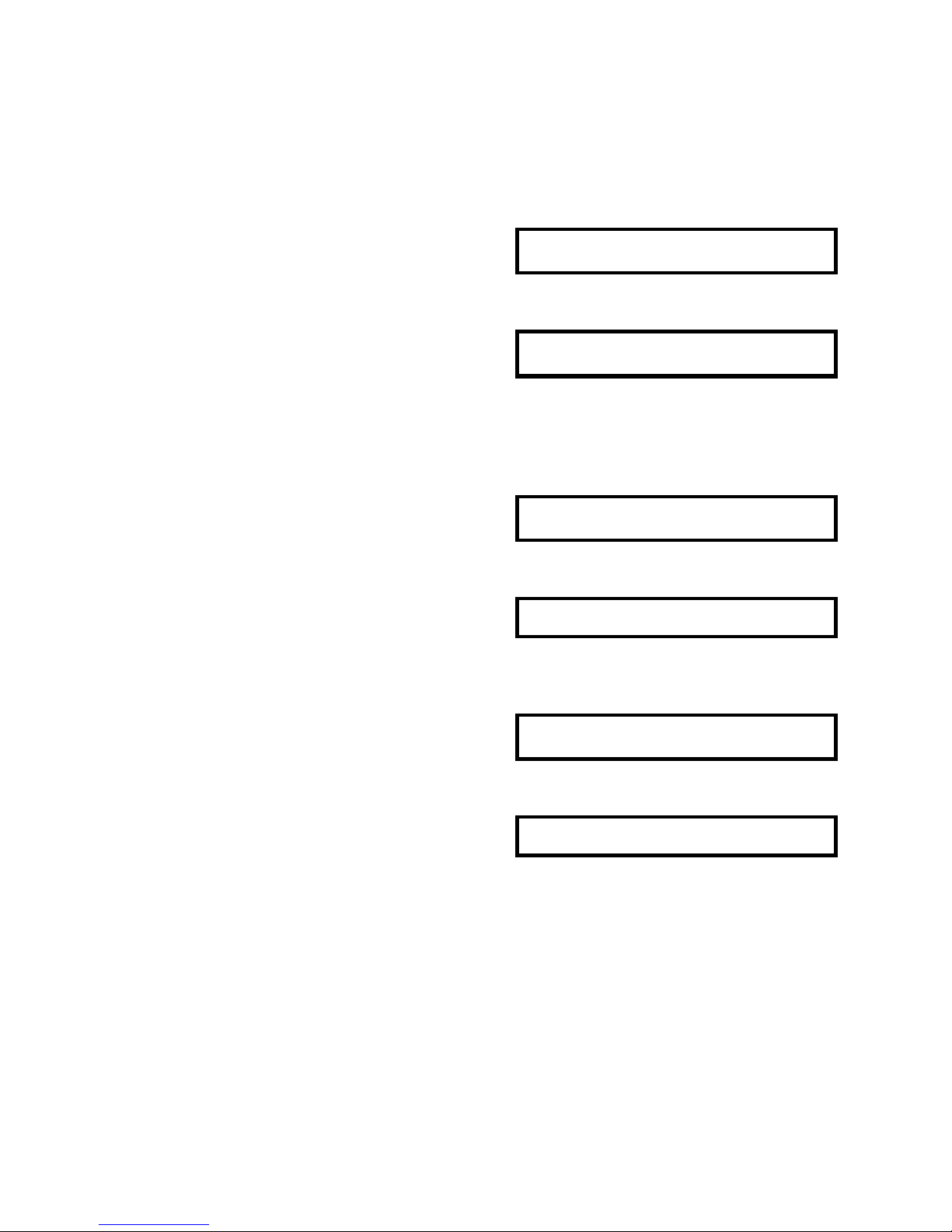
When powered on, the scale always gets into Operation Mode.
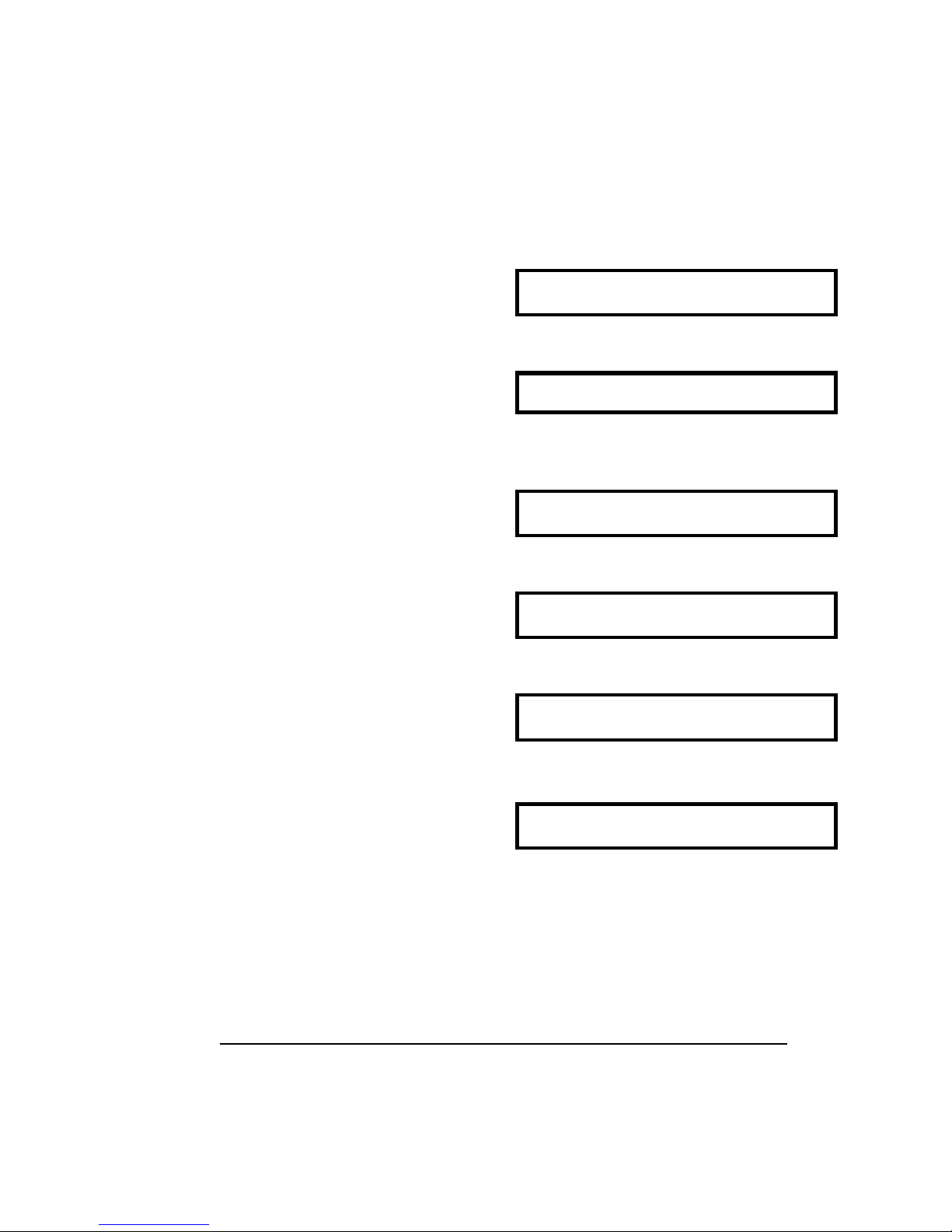
WEIGHT UNIT WEIGHT QUANTITY
0 . 0 0 0 . 0
∇ ∇ ∇ ∇ ∇
• • • • • • • • • • • • • • • • • • • •
ZERO NET 1 2 3 RECO IN OUT 1 2 3 4 5 6 7 8
(SCALE) JOB MODULE
STABLE KG INSUFF MEMORY
1. Change to PRG mode by depressing
[MODE] key.
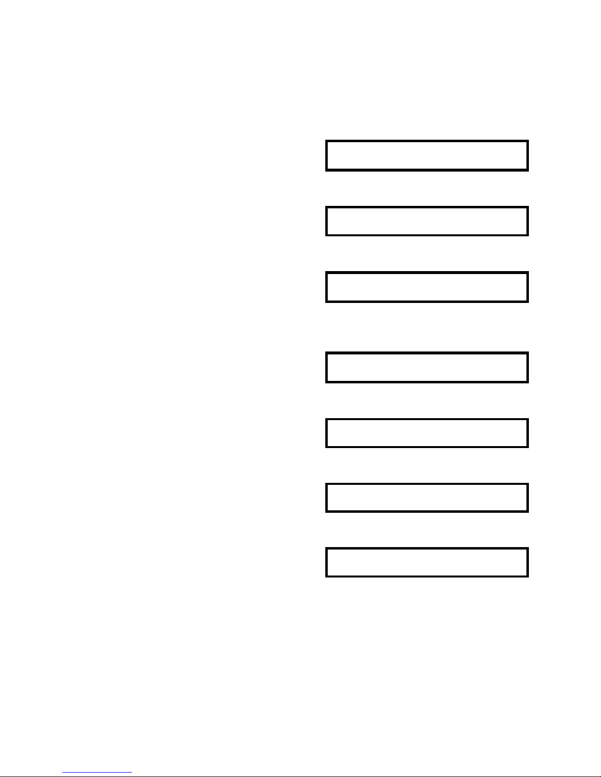
PROGRAM MODE
. . . . . . . . . . . . . . . . . . . .
Z S N K 1 2 3 I R M I O 1 2 3 4 5 6 7
8
2. Enter PRG mode by depressing [ENTER]
key.
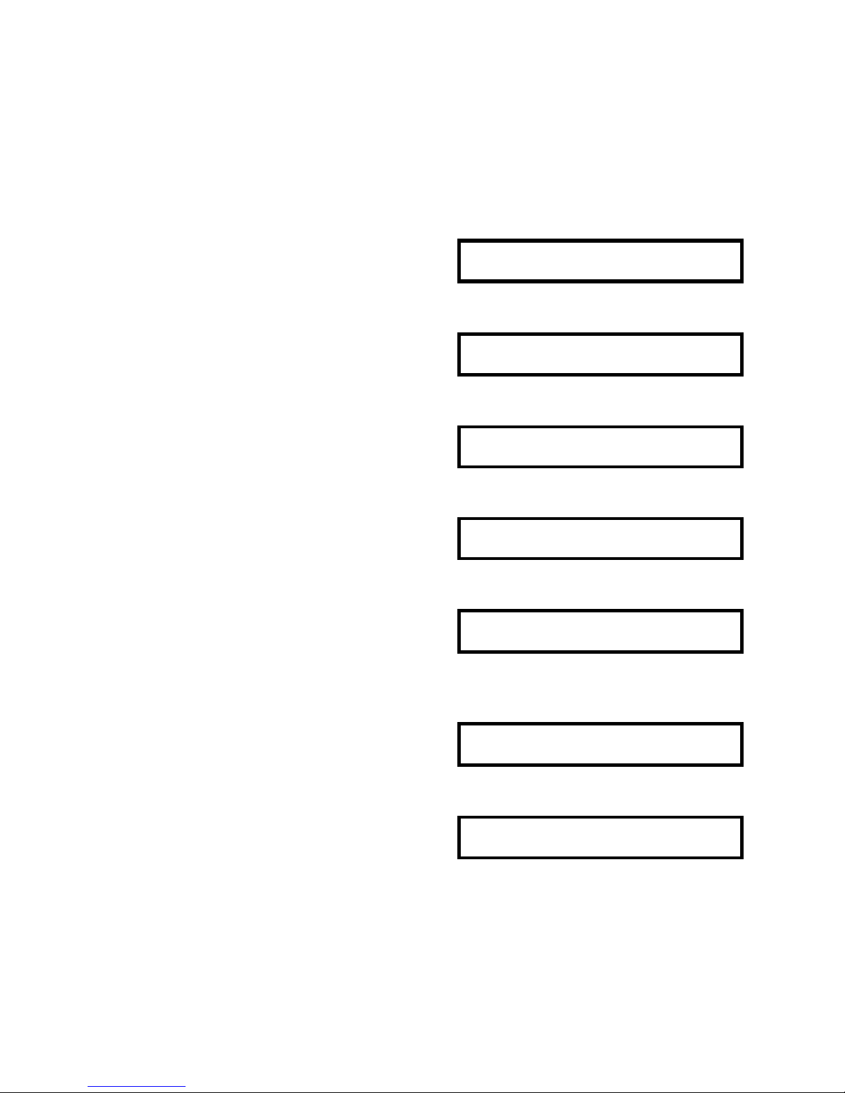
PRG: ID CODE
. . . . . . . . . . . . . . . . . . . .
Z S N K 1 2 3 I R M I O 1 2 3 4 5 6 7
8
3. Select each file in Programming Mode by
depressing
[TARE←] or [UNIT WEIGHT→] key.
PRG: FREE FORMAT SET
* Refer to 2.1b Data files and Function List.
. . . . . . . . . . . . . . . . . . . .
Z S N K 1 2 3 I R M I O 1 2 3 4 5 6 7
8
4. Enter the displayed mode by depressing
[ENTER] key
F.F= FREE FORMAT 1
. . . . . . . . . . . . . . . . . . . .
Z S N K 1 2 3 I R M I O 1 2 3 4 5 6 7
8
Note) Each file is changed in loop routine with [TARE←] or [UNIT WEIGHT→] key.
Page 19

18
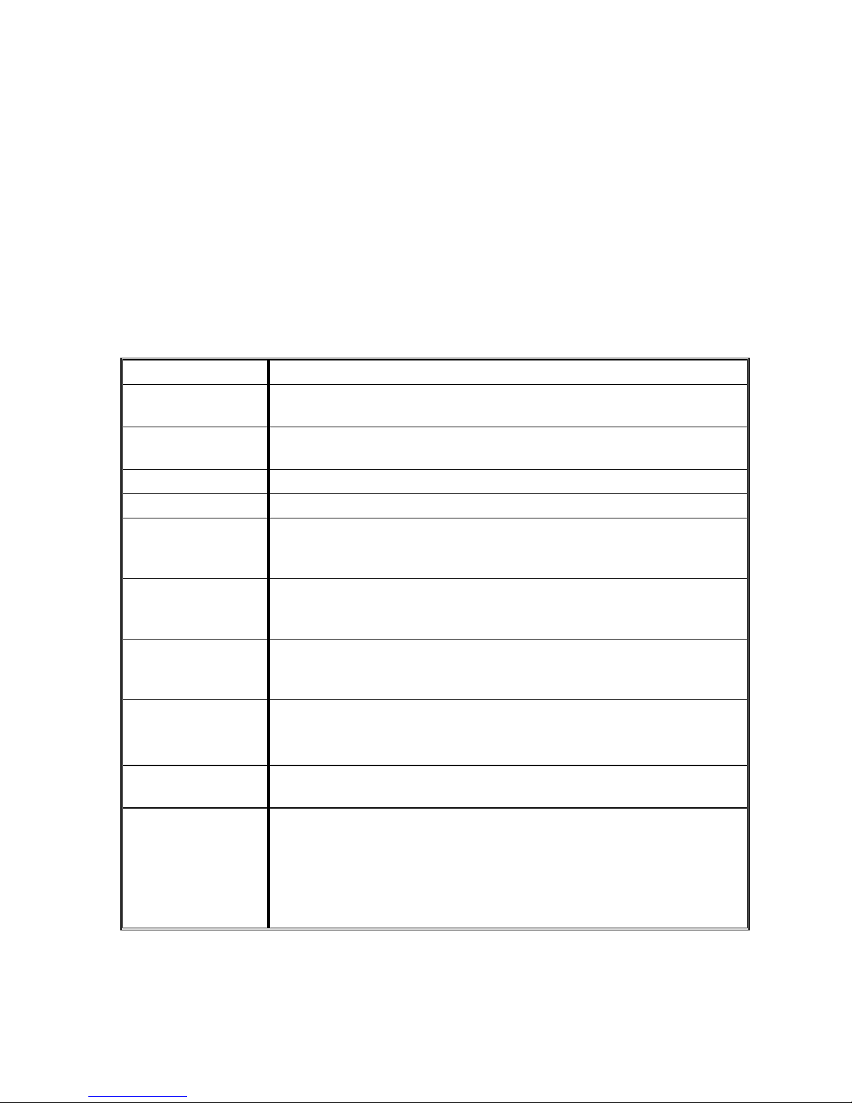
2.1b Data Files and Function List
The main data listed below is programmed in Program Mode.
Chapter #
Data File Remarks
2.2 I.D. Code File Programming ID code data in Memory
2.3 Date / Time Setting the internal clock.
2.4 Set Point Output File Programming Set Point value.
2.5 Title Contents File Programming text massage (title) on formats.
2.6 Preprint data File Programming text and position of Pre-print data.
2.7 Copy Format Function Copying a standard format to Free format.
2.8 Free Format File Programming Free format.
2.9 Shelf Location Format File Programming Shelf Location Format.
2.10 Shelf Location Limit File Setting Shelf Location Limit.
2.11 Address Data File Setting Address data.
Page 20

19
2.1c Key Function In Program Mode
[MODE] Key
To return to the initial screen of each modes without saving programmed data.
[AUTO/MANUAL] key
To return to the previous screen in programming.
[ENTER] key
To enter the next screen in each file.
To enter the programmed data into memory file.
[CLEAR] key
To clear mis-set data.
To enter the deletion screen of programmed data.
[TARE (←)] and [UNIT WEIGHT (→)] key
To select the headings in loop routines.
To move the cursor to left/right when there are purl cursors in a display.
[PLUS +] and [MINUS -] key
To select the data, when cursor of triangle indicator is blinking.
CURSORS
The cursors appear when programming data. The cursor shows not only the maximum
number of digits, but also the characteristic of the entering data.
1.) Light cursor ..... The numeric data should be entered with numeric keys.
2.) Blinking cursor .... The data should be selected with [ + ] or [ − ] key
Page 21
20
2.2 I.D. Code Setting
2.2a Item data in I.D. Code
ID code is used as the recognize code in calling part item in OPR mode and in various
reports. ID code allows to store item data in memory though program mode. The
following data can be programmed.
I.D. Code ID code is the recognize code of item data.
Unit Weight Unit weight can be entered by using sample counting or direct key
entry when unit weight is known.
Tare Weight Tare weight can entered by one touch tare entry or direct key entry
when unit weight is known.
Parts No. Parts number is usually used as production number.
Parts Name Parts name can also be changed in operation mode temporary.
Shelf Location No. Shelf location number can be programmed. According to the
range of shelf location number, the available data to enter for each
digit are changed. (Ref. to 2.7 Setting Shelf Location Limit)
Inventory After you set up the initial quality of stock, the data is renewed
along with receiving or shipping value. The accurate quantity of
stock in your warehouse can be handled with this number.
Threshold Threshold is the ideal quantity of stock. By comparing with the
actual quantity of inventory, lack or excess of stock can be
checked.
Set Point Output Set Point Output function alerts the operator to a predetermined
weight or quantity with alarm or external equipment.
(Ref to 2.4 Setting Set Point Output)
Scale According to the value of unit weight, the applicable capacity of
scale can be selected.
Auto Job No. Auto Job Operation number programmed in maintenance mode
can be selected for receiving/ shipping/ checking operation for
each parts item independently.
If Auto Job operation number is not assigned for ID code, Auto
Job Operation number programmed in Address 04/05/06
(OTHERS SPEC) are circulated.
Page 22

21
2.2b The maximum length of data
The maximum length of data will vary with each line of data from one digit to 32 digits.
Item Data Max. Length Available character
I.D. Code 16 digits Alpha-Numeric Data / Period
Unit Weight 5 Digits Numeric data / Decimal Point
Tare Weight 6 Digits Numeric data / Decimal Point
Parts No. 32 Digits Alpha-Numeric Data / Period / Space
Parts Name 32 Digits Alpha-Numeric Data / Period / Space
Shelf Location No. 8 Digits Alpha-Numeric Data
Inventory 8 Digits Numeric data and Minus
Threshold 8 Digits Numeric data
Set Point 7 Digits Numeric Data and decimal Point
Scale No. 1 Digit 0 ~ 3
Auto Job No. (Shipping) 1 Digit 1 ~ 5
Auto Job No. (Receiving) 1 Digit 1 ~ 5
Auto Job No. (Non-add) 1 Digit 1 ~ 5
Page 23

22
2.2c Programming I. D. Code.
1. Select ID code file in Program Mode and
depress [ENTER] key.
ID= ENTER ID CODE
. . . . . . . . . . . . . . . . . . . .
Z S N K 1 2 3 I R M I O 1 2 3 4 5 6 7 8
2. Enter I.D. Code.
Ex.) ABC-100#125 *1
ID= ABC-100#125
. . . . . . . . . . . . . . . . . . . .
Z S N K 1 2 3 I R M I O 1 2 3 4 5 6 7 8
3. Depress [CODE] key to enter the screen to
set each data. *2
* 0.0000 0. 0
∇ ∇ ∇ ∇
. . . . . . . . . . . . . . . . . . . .
Z S N K 1 2 3 I R M I O 1 2 3 4 5 6 7 8
PART NUMBER ENTRY
4. Enter Parts Number.
Ex.) H2-1357E-01
(13) H2-1375E-01
. . . . . . . . . . . . . . . . . . . .
Z S N K 1 2 3 I R M I O 1 2 3 4 5 6 7 8
5. Depress [SHIFT DOWN] key then [A/ PART
NO.
] key within 3 seconds.
* 0.0000 0. 0
∇ ∇ ∇ ∇
. . . . . . . . . . . . . . . . . . . .
Z S N K 1 2 3 I R M I O 1 2 3 4 5 6 7 8
PART NAME ENTRY
6. Enter Parts Name.
Ex.) Capacitor 1211E1
(16) C A P A C I T E R 1 2 1 1 E 1
. . . . . . . . . . . . . . . . . . . .
Z S N K 1 2 3 I R M I O 1 2 3 4 5 6 7 8
7. Depress [SHIFT DOWN] key then
[B/ PART NAME ] key within 3 seconds.
* 0.0000 0. 0
∇ ∇ ∇ ∇
. . . . . . . . . . . . . . . . . . . .
Z S N K 1 2 3 I R M I O 1 2 3 4 5 6 7 8
Note: *1) When entering a special character above alphabet key, depress [SHIFT UP]
key then alphabet key.
Note: *2) Item data can be entered in this screen. The programming order can be
proceeded at random. It is possible to omit any item data, if these are not
necessary to enter.
Page 24

23
Shelf Location no. entry
8. Enter location number.
Ex.) 01-15-07-1-E
(8) 0115071E
. . . . . . . . . . . . . . . . . . . .
Z S N K 1 2 3 I R M I O 1 2 3 4 5 6 7 8
9. Depress [SHIFT DOWN] key then [C
LOCATION] key within 3 seconds. *1
* 0.0000 0. 0
∇ ∇ ∇ ∇
. . . . . . . . . . . . . . . . . . . .
Z S N K 1 2 3 I R M I O 1 2 3 4 5 6 7 8
Inventory entry
10. Enter Inventory data.
Ex.) 5000 Pcs.
(4) 5000
. . . . . . . . . . . . . . . . . . . .
Z S N K 1 2 3 I R M I O 1 2 3 4 5 6 7 8
11. Depress [SHIFT DOWN] key then [D/
INVENT ] key within 3 seconds.
* 0.0000 0. 0
∇ ∇ ∇ ∇
. . . . . . . . . . . . . . . . . . . .
Z S N K 1 2 3 I R M I O 1 2 3 4 5 6 7 8
Threshold Entry
12. Enter Threshold data.
Ex.) 5100 Pcs.
(4) 5100
. . . . . . . . . . . . . . . . . . . .
Z S N K 1 2 3 I R M I O 1 2 3 4 5 6 7 8
13. Depress [SHIFT DOWN] key then [E/
TH’HOLD ] key within 3 seconds.
* 0.0000 0. 0
∇ ∇ ∇ ∇
. . . . . . . . . . . . . . . . . . . .
Z S N K 1 2 3 I R M I O 1 2 3 4 5 6 7 8
Note: *1) you cannot assign the data to the location number,the entered value might be
out of shelf location limit. Refer to 2.9 Setting Shelf Location Limit.
Page 25

24
Set Point entry
14. Depress [SHIFT DOWN] key then [F
/SETPOINT] key within 3 seconds. *1
S.P= 0 / 0
∇ ∇ ∇ ∇ ∇ ∇ ∇
Ex.) Set Point 1=200 Set Point 2=250
. . . . . . . . . . . . . . . . . . . .
Z S N K 1 2 3 I R M I O 1 2 3 4 5 6 7 8
15. Enter Set Point 1 and depress then [F
/SETPOINT] key.
S.P= 200 / 0
∇ ∇ ∇ ∇ ∇ ∇ ∇
. . . . . . . . . . . . . . . . . . . .
Z S N K 1 2 3 I R M I O 1 2 3 4 5 6 7 8
16. Move the cursor to right by pressing
[UNIT WEIGHT →].
S.P= 200 / 0
∇ ∇ ∇ ∇ ∇ ∇ ∇
. . . . . . . . . . . . . . . . . . . .
Z S N K 1 2 3 I R M I O 1 2 3 4 5 6 7
8
17. Enter Set Point 2 and depress then [F
/SETPOINT] key.
S.P= 200 / 250
∇ ∇ ∇ ∇ ∇ ∇ ∇
. . . . . . . . . . . . . . . . . . . .
Z S N K 1 2 3 I R M I O 1 2 3 4 5 6 7 8
18. Press [F /SETPOINT] key.
* 0.0000 0. 0
∇ ∇ ∇ ∇
. . . . . . . . . . . . . . . . . . . .
Z S N K 1 2 3 I R M I O 1 2 3 4 5 6 7 8
Scale No. Entry
19. Enter Scale No.
Ex.) Scale 1
(1) 1
. . . . . . . . . . . . . . . . . . . .
Z S N K 1 2 3 I R M I O 1 2 3 4 5 6 7 8
20. Depress [SHIFT DOWN] key then [G/ SCALE
] key within 3 seconds.
* 0.0000 0. 0
∇ ∇ ∇ ∇
. . . . . . . . . . . . . . . . . . . .
Z S N K 1 2 3 I R M I O 1 2 3 4 5 6 7 8
Note: *1) The setpoint value can be programmed to operate an item being weighed or
counted. Refer to 2.4 Setting Set Point Output.
Page 26
25
Auto Job No. Entry
21. Enter Scale No.
Ex.) Auto Job No. 1 for Receiving
(1) 1
Operation
. . . . . . . . . . . . . . . . . . . .
Z S N K 1 2 3 I R M I O 1 2 3 4 5 6 7 8
22. Depress [SHIFT DOWN] key then [H/ IN ]
key within 3 seconds. *1
* 0.0000 0. 0
∇ ∇ ∇ ∇
. . . . . . . . . . . . . . . . . . . .
Z S N K 1 2 3 I R M I O 1 2 3 4 5 6 7 8
Tare Entry
ONE TOUCH TARE
23. Place a container on the scale when
stable. Ex.) 0.0120kg
* 0.0120 0. 0
∇ ∇
. . . . . . . . . . . . . . . . . . . .
Z S N K 1 2 3 I R M I O 1 2 3 4 5 6 7 8
24. Depress [TARE] key. *2
* 0.0000 0. 0
∇ ∇ ∇ ∇
. . . . . . . . . . . . . . . . . . . .
Z S N K 1 2 3 I R M I O 1 2 3 4 5 6 7 8
DIGITAL TARE
23’. Enter Tare Weight value by numeric keys.
Ex.) 0.0120kg
(6) 0.0120
∇ ∇
. . . . . . . . . . . . . . . . . . . .
Z S N K 1 2 3 I R M I O 1 2 3 4 5 6 7 8
24’. Depress [TARE] key. *2
* - 0.0120 0. 0
∇ ∇ ∇ ∇
. . . . . . . . . . . . . . . . . . . .
Z S N K 1 2 3 I R M I O 1 2 3 4 5 6 7 8
Note: *1) Auto Job no. can be selected from 5 patterns which are programmed in
Maintenance Mode.
Auto Job no. for shipping and non-add operation can be selected with the same
operation as the receiving except using [I/OUT] or [J/NON-ADD]] key instead of [H]
key
Note: *2) To clear tare value, press [0] then [TARE] key.
Page 27
26
Unit Weight Entry
DIGITAL ENTRY
25. Enter Unit Weight Value with numeric
keys Ex.) 3.756kg/1000pcs.
(5) 3.756
. . . . . . . . . . . . . . . . . . . .
Z S N K 1 2 3 I R M I O 1 2 3 4 5 6 7 8
26. Press [UNIT WEIGHT] key. *1
* 0.0000 3.7560 0
∇ ∇ ∇
. . . . . . . . . . . . . . . . . . . .
Z S N K 1 2 3 I R M I O 1 2 3 4 5 6 7 8
UNIT WEIGHT SAMPLING
25’. Place sample pieces on scale.
Ex.) 0.015kg
* 0.0150 0. 0
∇ ∇
. . . . . . . . . . . . . . . . . . . .
Z S N K 1 2 3 I R M I O 1 2 3 4 5 6 7 8
26’. Enter sample number with numeric keys.
*2 Ex) 15
(2) 15
. . . . . . . . . . . . . . . . . . . .
Z S N K 1 2 3 I R M I O 1 2 3 4 5 6 7 8
27’. Press [PIECES] key. *3
---ADD 12
(The number of pieces needed appears in
display.)
. . . . . . . . . . . . . . . . . . . .
Z S N K 1 2 3 I R M I O 1 2 3 4 5 6 7 8
28’. Add the required pieces more and press
[PIECES] key again.
* 0.0270 0.9970 27
∇ ∇
. . . . . . . . . . . . . . . . . . . .
Z S N K 1 2 3 I R M I O 1 2 3 4 5 6 7 8
Note: *1) The unit weight value should be Unit Weight/1,000.
Note: *2) If using a sample of 10 pcs., press PIECES key without entering a number of
sample.
Note:*3) To have accurate unit weight calculation, the sample weight must be more
than the insufficient range of the scale. (Insufficient range = 0.0% ~ 0.7 % of
scale capacity) If sample weight is less than the range, the number of pieces
required for accurate sampling would be displayed in PROCEDURE 27.
The procedure on 27 and 28 will be skipped if sample weight is sufficient.
Page 28

27
29’) Add more pieces 1 to 3 times as many as
the first sample. *1
* 0.0835 0.9970 84
∇ ∇ ∇
. . . . . . . . . . . . . . . . . . . .
Z S N K 1 2 3 I R M I O 1 2 3 4 5 6 7 8
30’) Press [PIECES] key.
* 0.0835 0.9917 84
∇ ∇
. . . . . . . . . . . . . . . . . . . .
Z S N K 1 2 3 I R M I O 1 2 3 4 5 6 7 8
NOTE: *1) When the unit weight is developed though sampling, the accuracy can be
improved by increasing the sample size using recomputing feature. This
function works only when the “RECOMP” sign lit.
After you set all the item data and ID code, depress [ENTER] key to enter the data
into MEMORY FILE. The display is back to the initial screen of ID code entry.
Page 29

28
2.2d Delete Programmed ID code and Item Data
Delete ID code
1. Select ID code file in Program Mode and
depress [ENTER] key.
ID= ENTER ID CODE
. . . . . . . . . . . . . . . . . . . .
Z S N K 1 2 3 I R M I O 1 2 3 4 5 6 7 8
2. Enter I.D. Code which is in memory file.
Ex.) ABC-100#125
ID= ABC-100#125
. . . . . . . . . . . . . . . . . . . .
Z S N K 1 2 3 I R M I O 1 2 3 4 5 6 7 8
3. Depress [CODE] key. * 1
DEL A B C - 1 0 0 # 1 2 5
. . . . . . . . . . . . . . . . . . . .
Z S N K 1 2 3 I R M I O 1 2 3 4 5 6 7 8
4. Press [Y] key to delete the data. *2
ID= ENTER ID CODE
. . . . . . . . . . . . . . . . . . . .
Z S N K 1 2 3 I R M I O 1 2 3 4 5 6 7 8
Note: *1) If the entering ID code exists on ID memory file, the deletion screen appears
automatically.
Note: *2) To escape from the deletion screen, press [N] key. The screen to set Item
data will appear.
Delete Item data on ID code
1. Select ID code file in Program Mode and
depress [ENTER] key.
ID= ENTER ID CODE
. . . . . . . . . . . . . . . . . . . .
Z S N K 1 2 3 I R M I O 1 2 3 4 5 6 7 8
2. Enter I.D. Code which is in memory file.
Ex.) ABC-100#125
ID= ABC-100#125
. . . . . . . . . . . . . . . . . . . .
Z S N K 1 2 3 I R M I O 1 2 3 4 5 6 7 8
Page 30

29
3. Depress [CODE] key. * 1
DEL A B C - 1 0 0 # 1 2 5
. . . . . . . . . . . . . . . . . . . .
Z S N K 1 2 3 I R M I O 1 2 3 4 5 6 7 8
4. Press [N] key to enter Item Setting Screen.
* 0.0000 0.9917 0
∇ ∇ ∇
. . . . . . . . . . . . . . . . . . . .
Z S N K 1 2 3 I R M I O 1 2 3 4 5 6 7 8
5. Select the item data to delete. (Depress
[SHIFT DOWN] then [B] key.)
P . N A=C A P A C I T O R 1 2 1 1 E 1
Ex.) Parts Name
. . . . . . . . . . . . . . . . . . . .
Z S N K 1 2 3 I R M I O 1 2 3 4 5 6 7 8
6. Press [CLEAR] key to enter the deletion
screen.
D E L C A P A C I T O R 1 2 1 1 E 1
. . . . . . . . . . . . . . . . . . . .
Z S N K 1 2 3 I R M I O 1 2 3 4 5 6 7 8
7. Press [Y] key to delete.
* 0.0000 0.9917 0
∇ ∇ ∇
. . . . . . . . . . . . . . . . . . . .
Z S N K 1 2 3 I R M I O 1 2 3 4 5 6 7 8
Page 31

30
2.3 Date/Time Setting
The built-in clock automatically up-dates date/time once they are set. The present date
and time are printed on labels and reports.
Date (Month / Day / Year ) ----- 2 digits for each part
Time -------------------------------- 4 digits
The date format can be selected in Specification Setting.
1. Enter Program Mode.
PRG: ID CODE
. . . . . . . . . . . . . . . . . . . .
Z S N K 1 2 3 I R M I O 1 2 3 4 5 6 7 8
2. Select DATE/TIME file with [UNIT WEIGHT
→].
PRG: DATE/ TIME
. . . . . . . . . . . . . . . . . . . .
Z S N K 1 2 3 I R M I O 1 2 3 4 5 6 7 8
3. Press [ENTER] key.
D/T= 1 8 - 0 6 - 9 6 / 2 0 : 3 0
. . . . . . . . . . . . . . . . . . . .
Z S N K 1 2 3 I R M I O 1 2 3 4 5 6 7 8
4. Enter date and time.
Ex.) July 20, 1996 PM 19:56
D/T= 2 0 0 7 9 6 2 1 5 6
. . . . . . . . . . . . . . . . . . . .
Z S N K 1 2 3 I R M I O 1 2 3 4 5 6 7 8
5. Depress [ENTER] key.
PRG: DATE/ TIME
. . . . . . . . . . . . . . . . . . . .
Z S N K 1 2 3 I R M I O 1 2 3 4 5 6 7 8
Page 32

31
2.4 Set Point Output Setting
2 target values can be programmed for all items being weighed or counted in this file.
Beep sounds let operator know when the counting weight value is equal to ( or over) the
target value, so that operator can check the external or lack of its approach.
The setpoints can be set to each code number in programming I.D. code. (Refer to
2.2C Programming I.D. code) If no data programmed in I.D. code, the general setpoint
in this file is enabled.
The combination of Setpoint 1 and Setpoint 2 can be selected as following in
Maintenance Mode.
COMBINATION SETPOINT 1 SET POINT 2
Q’TY & % Q’TY % of SETPOINT 1
Q’TY & % (To Stop Buzzer,
Recomputing Process Is Required.)
Q’TY % of SETPOINT 1
WEIGHT & % WEIGHT % of SETPOINT 1
LOW WEIGHT & HIGH WEIGHT LOW WEIGHT HIGH WEIGHT
LOW Q’TY & HIGH Q’TY LOW Q’TY HIGH Q’TY
Example) Combination is Quantity & Percentage.
(Setpoint 1= 2,000 Pcs / Setpoint 2 = 80%)
0 80% 2000 Pcs
Intermittent Buzzer Continuous Buzzer
1. Enter Program Mode.
PRG: ID CODE
. . . . . . . . . . . . . . . . . . . .
Z S N K 1 2 3 I R M I O 1 2 3 4 5 6 7 8
2. Select DATE/TIME file with
[UNIT WEIGHT →] twice.
PRG: SET POINT
. . . . . . . . . . . . . . . . . . . .
Z S N K 1 2 3 I R M I O 1 2 3 4 5 6 7 8
Page 33

32
3. Press [ENTER] key.
S.P= 0 / 0
∇ ∇ ∇ ∇ ∇ ∇ ∇
. . . . . . . . . . . . . . . . . . . .
Z S N K 1 2 3 I R M I O 1 2 3 4 5 6 7 8
4. Enter Setpoint value 1 and depress [F
SETPOINT] key.
S.P= 2 0 0 0 / 0
∇ ∇ ∇ ∇ ∇ ∇ ∇
Setpoint 1 = 2,000 Pcs.
. . . . . . . . . . . . . . . . . . . .
Z S N K 1 2 3 I R M I O 1 2 3 4 5 6 7 8
5. Move the cursor to Setpoint 2 by pressing
[Unit Weight →] key.
S.P= 2 0 0 0 / 0
∇ ∇ ∇ ∇ ∇ ∇ ∇
. . . . . . . . . . . . . . . . . . . .
Z S N K 1 2 3 I R M I O 1 2 3 4 5 6 7 8
6. Enter Setpoint value 2 and depress [F
SETPOINT] key.
S.P= 2 0 0 0 / 8 0 . 0
∇ ∇ ∇ ∇ ∇ ∇ ∇
Setpoint 2 = 80%
. . . . . . . . . . . . . . . . . . . .
Z S N K 1 2 3 I R M I O 1 2 3 4 5 6 7 8
7. Depress [ENTER] key.
PRG: SET POINT
. . . . . . . . . . . . . . . . . . . .
Z S N K 1 2 3 I R M I O 1 2 3 4 5 6 7 8
Page 34

33
2.5 Title Contents Setting
The title contents is the text data (the fixed data) on label format, such as “Tare”, “QTY”
as the following table. Because the tile contents are the common with all the formats
(standard formats and Free formats), if the defult contents is changed, the text contents
in standard formats are changed, too.
Printing position and character size of title contents can be programmed in Free Format
File. (Ref. to 2.8 Setting Free Format). 16 kinds of title contents can be programmed.
The maximum digits for each contents are 16 digits.
2.5a Defult data list
CONTENTS NO. DEFAULT DATA PRINT STATUS
Item Label
Total Label
Gross Label
T# 1 GROSS X X
{
T# 2 NET X X
{
T# 3 TARE X X
{
T# 4 P.NAME
{ { {
T# 5 P.NO.
{ { {
T# 6 ID CODE
{ { {
T# 7 LOT NO.
{ { {
T# 8 QTY
{ {
X
T# 9 W/1000
{ { {
T# 10 SEQ NO.
{ { {
T# 11 UW/
{ { {
T# 12 QTY
{ {
X
T# 13 TARE
{ { {
T# 14 GROSS
{ { {
T# 15 NET
{ { {
T# 16 TARE
{ { {
Page 35

34
2.5b Programming Title Contents
1. Enter Program Mode.
PRG : I D C O D E
. . . . . . . . . . . . . . . . . . . .
Z S N K 1 2 3 I R M I O 1 2 3 4 5 6 7 8
2. Select Title Contents with [ Unit Weight →]
key three times.
PRG : T I T L E C O N T E N T S
. . . . . . . . . . . . . . . . . . . .
Z S N K 1 2 3 I R M I O 1 2 3 4 5 6 7 8
3. Depress [ENTER] key.
TITLE CONTENTS = N O . 1
♦♦♦♦♦
. . . . . . . . . . . . . . . . . . . .
Z S N K 1 2 3 I R M I O 1 2 3 4 5 6 7 8
♦ = Blinking Cursor
4. Select Title Contents No. with [+] and [-]
key. Ex.) Title Contents No. = 3
TITLE CONTENTS = N O . 3
♦♦♦♦♦
. . . . . . . . . . . . . . . . . . . .
Z S N K 1 2 3 I R M I O 1 2 3 4 5 6 7 8
5. Depres [ENTER] key.
(The defult data appears.)
T3 = TARE
. . . . . . . . . . . . . . . . . . . .
Z S N K 1 2 3 I R M I O 1 2 3 4 5 6 7 8
6. Enter the data.
Ex.) Title 3 = Unit Weight
T3 = UNIT WEIGHT
. . . . . . . . . . . . . . . . . . . .
Z S N K 1 2 3 I R M I O 1 2 3 4 5 6 7 8
7. Depress [ENTER] key to store the data into
memory.
TITLE CONTENTS = N O . 3
♦♦♦♦♦
. . . . . . . . . . . . . . . . . . . .
Z S N K 1 2 3 I R M I O 1 2 3 4 5 6 7 8
Page 36

35
2.5c Delete Title Contents Data
1. Select Title Contents with [ Unit Weight →]
key three times.
PRG : T I T L E C O N T E N T S
. . . . . . . . . . . . . . . . . . . .
Z S N K 1 2 3 I R M I O 1 2 3 4 5 6 7 8
2. Depress [ENTER] key.
TITLE CONTENTS = N O . 1
♦♦♦♦♦
. . . . . . . . . . . . . . . . . . . .
Z S N K 1 2 3 I R M I O 1 2 3 4 5 6 7 8
♦ = Blinking Cursor
3. Select Title Contents No. to delete.
Ex.) Title Contents No. = 3
TITLE CONTENTS = N O . 3
♦♦♦♦♦
. . . . . . . . . . . . . . . . . . . .
Z S N K 1 2 3 I R M I O 1 2 3 4 5 6 7 8
4. Depres [ENTER] key.
(The defult data appears.)
T3 = TARE
. . . . . . . . . . . . . . . . . . . .
Z S N K 1 2 3 I R M I O 1 2 3 4 5 6 7 8
5. Enter the deletion screen by pressing
[CLEAR] key.
DEL TARE
. . . . . . . . . . . . . . . . . . . .
Z S N K 1 2 3 I R M I O 1 2 3 4 5 6 7 8
6. Depress [Y] to delete data. * 1
T16=
. . . . . . . . . . . . . . . . . . . .
Z S N K 1 2 3 I R M I O 1 2 3 4 5 6 7 8
Note: *1) To escape from the deletion screen, press [N] key.
Page 37

36
2.6 Pre-print Data Setting
The item data cannot be print on the bottom 10mm of the label for peeling the label off
smoothly.
In the area, the fixed (pre-printing) data, such as vendor name or company motto, can
be printed. The contents and the print position of preprint data should be programmed
for printing. Up to 3 contents can be printed in this area. One contents can be
programmed 32 digits at maximum.
Back paper
PREPRINTING AREA
10mm
Page 38

37
2.6a Programming Pre-print Contents
1. Enter Program Mode.
PRG : I D C O D E
. . . . . . . . . . . . . . . . . . . .
Z S N K 1 2 3 I R M I O 1 2 3 4 5 6 7 8
2. Select Title Contents with [ Unit Weight →]
key four times.
PRG :P R E . P R I N T E D C O N T
. . . . . . . . . . . . . . . . . . . .
Z S N K 1 2 3 I R M I O 1 2 3 4 5 6 7 8
3. Depress [ENTER] key.
PRE= P R I N T C O N T E N T S
. . . . . . . . . . . . . . . . . . . .
Z S N K 1 2 3 I R M I O 1 2 3 4 5 6 7 8
4. Depress [ENTER] key to program the Pre-
print Contents.
CONTENTS = N O . 1
♦♦♦♦♦
. . . . . . . . . . . . . . . . . . . .
Z S N K 1 2 3 I R M I O 1 2 3 4 5 6 7 8
♦ = Blinking Cursor
5. Select Contents No. with [+] and [-] key.
Ex.) Contents No. = 2
CONTENTS = N O . 2
♦♦♦♦♦
. . . . . . . . . . . . . . . . . . . .
Z S N K 1 2 3 I R M I O 1 2 3 4 5 6 7 8
6. Depres [ENTER] key.
C2=
. . . . . . . . . . . . . . . . . . . .
Z S N K 1 2 3 I R M I O 1 2 3 4 5 6 7 8
7. Enter the data.
Ex.) Contents = Teraoka Seiko
(13) T E R A O K A S E I K O
. . . . . . . . . . . . . . . . . . . .
Z S N K 1 2 3 I R M I O 1 2 3 4 5 6 7 8
8. Depress [ENTER] key to store the data into
memory.
CONTENTS = N O . 2
♦♦♦♦♦
. . . . . . . . . . . . . . . . . . . .
Z S N K 1 2 3 I R M I O 1 2 3 4 5 6 7 8
Page 39
38
2.6b Delete Pre-Print Contents Data
1. Select Pre-Print Contents with [ Unit Weight
→] key Four times.
PRG : P R E . P R I N T E D C O N T
. . . . . . . . . . . . . . . . . . . .
Z S N K 1 2 3 I R M I O 1 2 3 4 5 6 7 8
2. Depress [ENTER] key.
PRE= P R I N T C O N T E N T S
. . . . . . . . . . . . . . . . . . . .
Z S N K 1 2 3 I R M I O 1 2 3 4 5 6 7 8
3. Depress [ENTER] key delete the Pre-print
Contents.
CONTENTS = N O . 1
♦♦♦♦♦
. . . . . . . . . . . . . . . . . . . .
Z S N K 1 2 3 I R M I O 1 2 3 4 5 6 7 8
♦ = Blinking Cursor
4. Select Contents No. with [+] and [-] key.
Ex.) Contents No. = 2
CONTENTS = N O . 2
♦♦♦♦♦
. . . . . . . . . . . . . . . . . . . .
Z S N K 1 2 3 I R M I O 1 2 3 4 5 6 7 8
5. Depres [ENTER] key.
C2= T E R A O K A S E I K O
. . . . . . . . . . . . . . . . . . . .
Z S N K 1 2 3 I R M I O 1 2 3 4 5 6 7 8
6. Depres [CLEAR] key to enter the deletion
screen.
DEL T E R A O K A S E I K O
. . . . . . . . . . . . . . . . . . . .
Z S N K 1 2 3 I R M I O 1 2 3 4 5 6 7 8
7. Depress [Y] to delete data. * 1
C2=
. . . . . . . . . . . . . . . . . . . .
Z S N K 1 2 3 I R M I O 1 2 3 4 5 6 7 8
Note: *1) To escape from the deletion screen, press [N] key.
Page 40

39
2.6c Print Position & Character Size of Pre-Print Data
PRINT POSITION
Printing position of preprinting data is decided with X and Y value. The X and Y value is
the interval from the fundamental point (X=0, Y=0) to where to print data. The both
values are graduated by unit “DOT”. (one dot is X=0.135mm, Y=0.135mm)
Y
ITEM DATA AREA
x PREPRINT DATA
y
X
(0,0)
⇓
Label Printing Direction
CHARACTER SIZE
Please refer to size of character and the magnification on APPENDEX II to select
Character Size.
DISPLAY OF PROGRAMMING SCREEN
C1 = X. 0. / Y. 0. / S. 0 / M. 0
* Printing position (X value, horizontal)
Numeric key entry
* Printing position (Y value, vertical)
Numeric key entry
* Character size
Selection from S.0 ~ S.5 with [+],[-] keys
* Magnification of character Size
Selection from M.0 ~ M.2 with [+],[-] keys
Note) In order not to print the data, set the printing position with 0 vale for X and Y.
Page 41
40
2.6d Programming Print Position & Character Size of
Pre-Print Data
1. Enter Program Mode.
PRG : I D C O D E
. . . . . . . . . . . . . . . . . . . .
Z S N K 1 2 3 I R M I O 1 2 3 4 5 6 7 8
2. Select Title Contents with [ Unit Weight →]
key four times.
PRG : P R E . P R I N T E D C O N T
. . . . . . . . . . . . . . . . . . . .
Z S N K 1 2 3 I R M I O 1 2 3 4 5 6 7 8
3. Depress [ENTER] key.
PRE= P R I N T C O N T E N T S
. . . . . . . . . . . . . . . . . . . .
Z S N K 1 2 3 I R M I O 1 2 3 4 5 6 7 8
4. Select Print Coordinate with [ Unit Weight
→] key.
PRE= P R I N T C O O R D I N A T E
. . . . . . . . . . . . . . . . . . . .
Z S N K 1 2 3 I R M I O 1 2 3 4 5 6 7 8
5. Depress [ENTER] key to program the print
position & character size of Pre-print
C O O R D I N A T E = N O . 1
♦♦♦♦♦
Contents.
. . . . . . . . . . . . . . . . . . . .
Z S N K 1 2 3 I R M I O 1 2 3 4 5 6 7 8
♦ = Blinking Cursor
6. Select Contents No. with [+] and [-] key.
Ex.) Contents No. = 2
C O O R D I N A T E = N O . 2
♦♦♦♦♦
. . . . . . . . . . . . . . . . . . . .
Z S N K 1 2 3 I R M I O 1 2 3 4 5 6 7 8
7. Depres [ENTER] key.
C2= X. 0 / Y. 0 / S.0 / M.0
∇∇∇∇
. . . . . . . . . . . . . . . . . . . .
Z S N K 1 2 3 I R M I O 1 2 3 4 5 6 7 8
∇= Lits Cursor
Page 42

41
8. Enter X value and depress[UNIT WEIGHT
→] key to move cursor to reight.
C2= X. 2 / Y. 0 / S.0 / M.0
∇∇∇∇
Ex.) X=2
. . . . . . . . . . . . . . . . . . . .
Z S N K 1 2 3 I R M I O 1 2 3 4 5 6 7 8
∇= Lits Cursor
9. Enter Y value and depress[UNIT WEIGHT
→] key to move cursor to reight.
C2= X. 2 / Y. 10 / S.0 / M.0
♦♦
Ex.) Y=10
. . . . . . . . . . . . . . . . . . . .
Z S N K 1 2 3 I R M I O 1 2 3 4 5 6 7 8
♦ = Blinking Cursor
10. Select character size by depressing [+] or
[-] key and depress [UNIT WEIGHT] key
C2= X. 2 / Y. 10 / S.2 / M.0
♦♦
to move cursor to right.
Ex.) Character Size = S2
. . . . . . . . . . . . . . . . . . . .
Z S N K 1 2 3 I R M I O 1 2 3 4 5 6 7 8
♦ = Blinking Cursor
11. Select character size by depressing [+] or
[-] key.
C2= X. 2 / Y. 10 / S.2 / M.1
♦♦
Ex.) Magnification = M1
. . . . . . . . . . . . . . . . . . . .
Z S N K 1 2 3 I R M I O 1 2 3 4 5 6 7 8
♦ = Blinking Cursor
12. Depress [ENTER] key to store data.
C O O R D I N A T E = N O . 2
♦♦♦♦♦
. . . . . . . . . . . . . . . . . . . .
Z S N K 1 2 3 I R M I O 1 2 3 4 5 6 7 8
Example)
Contents #1 = TERAOKA SEIKO (X=120 / Y=33 / S.2 / M.1)
Contents #2 = TEL(81)-3-3753-2131 (X=100 / Y=16 / S.0 / M.1)
Contents #3 = OFFICE HOURS 9:00 - 17:50 (X=80 / Y= 1 / S.0 / M.1)
Page 43

42
2.7 Copying Standard Format
If what label format you need to make is a similar to a standard format, you can make a
new format easily by copying the standard format then arranging print data.
When you select the standard format to be copied to, refer to the list of standard format
in APPENDEX I.
1. Enter Program Mode.
PRG : I D C O D E
. . . . . . . . . . . . . . . . . . . .
Z S N K 1 2 3 I R M I O 1 2 3 4 5 6 7 8
2. Select Title Contents with [ Unit Weight →]
key five times.
PRG : C O P Y F O R M A T
. . . . . . . . . . . . . . . . . . . .
Z S N K 1 2 3 I R M I O 1 2 3 4 5 6 7 8
3. Depress [ENTER] key.
CPY= ST NO. 1 → FR NO. 1
♦♦♦♦♦
. . . . . . . . . . . . . . . . . . . .
Z S N K 1 2 3 I R M I O 1 2 3 4 5 6 7 8
4. Select a standard format to be copied from
by pressing [ + ] or [ - ] key.
CPY= ST NO. 5 → FR NO. 1
♦♦♦♦♦
Ex.) Format No. = 5
. . . . . . . . . . . . . . . . . . . .
Z S N K 1 2 3 I R M I O 1 2 3 4 5 6 7 8
5. Move cursor to right by pressing [ Unit
Weight →] key.
CPY= ST NO. 5 → FR NO. 1
♦♦♦♦♦
Ex.) Free Format No. = 2
. . . . . . . . . . . . . . . . . . . .
Z S N K 1 2 3 I R M I O 1 2 3 4 5 6 7 8
♦ = Blinking Cursor
6.Select Free Format No. to be copied to by
pressing [ + ] or [ - ] key.
CPY= ST NO. 5 → FR NO. 2
♦♦♦♦♦
. . . . . . . . . . . . . . . . . . . .
Z S N K 1 2 3 I R M I O 1 2 3 4 5 6 7 8
7. Dpress [ENTER] key to copy the format.
PRG : C O P Y F O R M A T
. . . . . . . . . . . . . . . . . . . .
Z S N K 1 2 3 I R M I O 1 2 3 4 5 6 7 8
Page 44

43
2.8 Free Format Setting
DC-150 has 7 types of standard format, so that the suit label format for the system can
be used. Moreover, in the case that any types of standard format is not suit for what
required, “FREE FORMAT” can create your own label (item label, total label, and gross
label) by setting up printing angle, direction and size of the print items.
Accroding to the usage of the machine, DC-150 can print 3 types of labels: ITEM
LABEL, TOTAL LABEL and GROSS LABEL. The data base of one label format has all
3 type of labels. When you make a new label format, the format data for Item, Total,
and Gross labels are saved as one data base.
In Free Format Set Up
• 2 Free Format can be programmed.
• One item label, total label and gross label are avaialble to be set for each Free
Format number.
• Label size should be pre-set in Maintenance Mode.
2.8a Label Size
You can select label size from 11 size in Address 34 (PRINT SPEC)
64 x 40, 64 x 55, 64 x 77.5, 64 x 92, 64 x 120, 40 x 23, 40 x 28, 40 x 46, 40 x 62.5, 40 x
77.5, 40 x 92
Page 45

44
2.8b Programmable Item Data for Each Type of Label
This chart shows which data fields are printed on the three (3) standard types of labels.
ITEM DATA ITEM LABEL
TOTAL LABEL GROSS
LABEL
DATA TYPE
ID CODE
| | |
TYPE 1
PART NO.
| | |
TYPE 2
PARTS NAME
| | |
TYPE 2
LOT NO.
| | |
TYPE 2
WEIGHT
|
X X TYPE 1
WEIGHT UNIT (g/ LB)
|
X X TYPE 1
“/” MARK FOR WEIGHT
|
X X TYPE 1
UNIT WEIGHT
|
X X TYPE 1
UNIT WEIGHT UNIT (g/ lb)
|
X X TYPE 1
“-” MARK FOR QTY
|
X X TYPE 1
QUANTITY
| |
X TYPE 1
QUANTITY UNIT (symbol)
| |
X TYPE 1
DATE
| | |
TYPE 1
TIME
| | |
TYPE 1
TASK CONTENTS
| |
X TYPE 1
SUM TOTALING
X
|
X TYPE 1
SUM COUNT
X
|
X TYPE 1
GROSS WEIGHT
|
X X TYPE 1
GROSS UNIT (g/lb)
|
X X TYPE 1
NET WEIGHT
|
X X TYPE 1
NET UNIT (g/lb)
|
X X TYPE 1
TARE WEIGHT
|
X X TYPE 1
TARE UNIT (g/lb)
|
X X TYPE 1
SEQUENCE NO. DATA
| |
X TYPE 1
BAR-CODE (ID)
| | |
TYPE 3
BAR-CODE (PART NO)
| | |
TYPE 3
BAR-CODE (LOT NO.)
| | |
TYPE 3
BAR-CODE (QTY)
| |
X TYPE 3
BAR-CODE (TARE)
|
X
|
TYPE 3
BAR-CODE (UNIT WEIGHT)
|
X X TYPE 3
BAR-CODE (GROSS WEIGHT)
|
X
|
TYPE 3
BAR-CODE (NET WEIGHT)
|
X
|
TYPE 3
TITLE CONTENTS #1 ~ 3
X X
|
TYPE 1
TITLE CONTENTS #4 ~ 7
| | |
TYPE 1
TITLE CONTENTS #8
| |
X TYPE 1
- Continue -
Page 46

45
- Continued -
ITEM DATA ITEM LABEL
TOTAL LABEL GROSS
LABEL
DATA BASE
TITLE CONTENTS #9 ~11
| | |
TYPE 1
TITLE CONTENTS #12
| |
X TYPE 1
TITLE CONTENTS #13 ~16
| | |
TYPE 1
GROSS WEIGHT (GROSS)
X X
|
TYPE 1
GROSS UNIT (GROSS)
X X
|
TYPE 1
UNIT WEIGHT (GROSS)
X X
|
TYPE 1
NET WEIGHT (GROSS)
X X
|
TYPE 1
NET UNIT (GROSS)
X X
|
TYPE 1
TARE WEIGHT (GROSS)
X X
|
TYPE 1
TARE UNIT (GROSS)
X X
|
TYPE 1
ADDRESS CONTENTS #1~ 5
| | |
TYPE 1
NOTE: 1) In minus transaction, item label issued along with using [-] keys. Minus mark
is printed on label.
NOTE: 2) TASK CONTENTS is “IN”, “OUT”, “NON-ADD”.
2.8c Data Type
Every filed can have different characteristics, therefore, data can vary from label format
to label format. Three types of data can vary into accordance with the programming
parameters. By the divided types, the programming procedures are explained in 2.8
Programming Free Format.
TO SET FOR ITEM DATA
TYPE 1 TYPE 2 TYPE 3
X position
| | |
Y position
| | |
Character size
| |
X
Magnification of character
| |
X
Line number
X
|
X
Max. digits in the selected line
X
|
X
Height of bar-code
X X
|
Print angle of bar-code
X X
|
| = Required X = Not Required
Note:1) Bar-code is selectable in SPEC for print.
Page 47

46
2.8d Printing Position
Printing position of item data is decided with X and Y value. The X and Y value is the
interval from the fundamental point (X=0, Y=0) to print preprinting data. The both
values are graduated by one dot unit. (one dot is 0.135mm x 0.135mm)
Y
x ITEM DATA
(0,0)
y
X
PRE PRINTING AREA
10mm
⇓ label printing
direction
NOTE: 1) The item data can not be printed on the bottom 10mm of label.
NOTE: 2) The printing position of item data, which you need not to print, is to be set at
the start point where X=0 and Y=0.
Page 48

47
2.8e Label Angle And Bar-Code Angle
All item data except bar-codes can be printed in 4 different angles by changing label
angle. The printing position of item data differ among the different angles as the
following. The print angle of bar-code data can be programmed independently in each
data base.
y y
x ITEM DATA
x
(0,0) y
(0,0)
y
TERAOKA SEIKO (PRE-PRINT) TERAOKA SEIKO (PRE-PRINT)
0 degree 90 degree
y y
x
x
y
y
(0,0)
(0,0)
TERAOKA SEIKO (PRE-PRINT) TERAOKA SEIKO (PRE-PRINT)
180 degree 270 degree
(0,0)
2.8f Character Size and Magnifications
(Height of Bar-code)
• Refer to the list of character size in APPENDEX II to select the combination of
character size and magnifications for preprinting data.
• Height of bar-code can be selected from 10mm, 15mm, 20mm, 25mm, 30mm.
Page 49
48
2.8g Programming Screen
Programming screen for data type 1
C1 = X. 0. / Y. 0. / S. 0 / M. 0
* Printing position (X value, horizontal)
Numeric key entry
* Printing position (Y value, vertical)
Numeric key entry
* Character size
Selection from S.0 ~ S.5 with [+],[-] keys
* Magnification of character Size
Selection from M.0 ~ M.2 with [+],[-] keys
Note) In order not to print the data, set the printing position with 0 vale for X and Y.
Programming screen for data type 2
L.4 / D.08 / X. 467 / M. 0
* Line Number
Selection from L.1 ~ L.4 with [+] or [-]
key
* The number of digits in the line
Numeric key entry (0~8)
* Horizontal / Vertical Selection
Selection with [+] or [-] key. (X or Y)
* Printing position (X value or Y value)
Numeric key entry
* Character size / Magnification Selection
Selection with [+],[-] keys. (S or M)
* Character Size or Magnification Size
Selection with [+],[-] keys.
(S.=S.0~S.5/M.= M.0~M.2)
Page 50

49
Programming screen for data type 3
C1 = X. 0. / Y. 0. / H. 4 / A. 3
* Printing position (X value, horizontal)
Numeric key entry
* Printing position (Y value, vertical)
Numeric key entry
* Height of bar-code
Selection (H.0~H.4) with [+],[-] keys
* Printing angle of bar-code
Selection (A.0 ~ A.3)with [+],[-] keys
Note: 1) Selection of height of bar-code
H.0 = 10mm, H.1 = 15mm, H.2 = 20mm, H.3 = 25mm, H.4 = 30mm)
Note: 2) Selection of printing angle of bar-code
A.0 = 0 degree, A.1 = 90 degree, A-2 =180 degree, A.3 = 270 degree
2.8h Function Key
[UNIT WEIGHT←] key and [TARE→] key
To select item data in loop routine
To move the cursor in a display
[PLUS + ] and [MINUS - ] key
To select data when cursor of triangle indicator is blinking
[AUTO /MANUAL] key
To move back to the previous screen.
Page 51

50
2.8i Programming Operation
1. Enter Program Mode.
PRG : I D C O D E
. . . . . . . . . . . . . . . . . . . .
Z S N K 1 2 3 I R M I O 1 2 3 4 5 6 7 8
2. Select Free Formats with [ Unit Weight →]
key six times.
PRG : FREE FORMAT SET
. . . . . . . . . . . . . . . . . . . .
Z S N K 1 2 3 I R M I O 1 2 3 4 5 6 7 8
3. Depress [ENTER] key.
F. F = FREE FORMAT 1
. . . . . . . . . . . . . . . . . . . .
Z S N K 1 2 3 I R M I O 1 2 3 4 5 6 7 8
4. Select FREE FORMAT # by depressing
[UNIT WEIGHT←] or [TARE→] key.
F.F = FREE FORMAT 2
Ex.) Format = no.2
. . . . . . . . . . . . . . . . . . . .
Z S N K 1 2 3 I R M I O 1 2 3 4 5 6 7 8
5. Depres [ENTER] key.
FM2 = PRINT ANGLE
. . . . . . . . . . . . . . . . . . . .
Z S N K 1 2 3 I R M I O 1 2 3 4 5 6 7 8
6. Depress [ENTER] key.
FM2 = ANGLE (°) 0
. . . . . . . . . . . . . . . . . . . .
Z S N K 1 2 3 I R M I O 1 2 3 4 5 6 7 8
7. Select label angle by depressing
[ + ] or [ - ] key..
FM2 = ANGLE (°) 0
. . . . . . . . . . . . . . . . . . . .
Z S N K 1 2 3 I R M I O 1 2 3 4 5 6 7 8
Page 52

51
8. Depress [ENTER] key.
(Ready for setting the print positions for
M2 = ID CODE
Item data)
. . . . . . . . . . . . . . . . . . . .
Z S N K 1 2 3 I R M I O 1 2 3 4 5 6 7 8
9. Select item data by depressing
[UNIT WEIGHT←] or [TARE→] key.
M2 = PART NAME
. . . . . . . . . . . . . . . . . . . .
Z S N K 1 2 3 I R M I O 1 2 3 4 5 6 7 8
Set Print Items in the procedure in 2.8I Item setting.
10. Store the data to F2 by pressing [ENTER]
key.
F.F = FREE FORMAT 2
. . . . . . . . . . . . . . . . . . . .
Z S N K 1 2 3 I R M I O 1 2 3 4 5 6 7 8
Note:) While programming print data, the programmed data may be printed in test label.
With uins this function, you can check if the print position is proper and adjust the
data accordingly.
In the selection screen for item data such as the screen in procedure 9, press the
following keys for test printing.
♦ [ SP kg/lb ] key ...... Test Printing of Item Label
♦ [ PEICES ] key ...... Test Printing of Item Label (on Minus transaction)
♦ [ CODE ] key ...... Test Printing of Total Label
♦ [M NET/GROSS] key ...... Test Printing of Gross Label
Page 53

52
Start for A. ITEM DATA SETTING ( DATA TYPE 1)
1. Select Print Item.
Ex.) ID code
FM2 = ID CODE
. . . . . . . . . . . . . . . . . . . .
Z S N K 1 2 3 I R M I O 1 2 3 4 5 6 7 8
2. Press [ENTER] key.
ID= X. 0 /Y. 0. / S.0 / M.0
∇ ∇ ∇
. . . . . . . . . . . . . . . . . . . .
Z S N K 1 2 3 I R M I O 1 2 3 4 5 6 7 8
3. Enter X value and press [U.W.→] key to
move the cursor to right.
ID= X. 52 /Y. 0. / S.0 / M.0
∇ ∇ ∇
Ex.) X value= 52
. . . . . . . . . . . . . . . . . . . .
Z S N K 1 2 3 I R M I O 1 2 3 4 5 6 7 8
4. Enter Y value and press [U.W.→] key to
move the cursor to right.
ID= X. 52 /Y. 15. / S.0 / M.0
♦♦
Ex.) Y value= 15
. . . . . . . . . . . . . . . . . . . .
Z S N K 1 2 3 I R M I O 1 2 3 4 5 6 7 8
♦ = Blinking Cursor
5. Select character size by depressing [+] or [-]
key and depress [U.W.→] key to move the
ID= X. 52 /Y. 15. / S.2 / M.0
♦♦
cursor to right. Ex.) S=2
. . . . . . . . . . . . . . . . . . . .
Z S N K 1 2 3 I R M I O 1 2 3 4 5 6 7 8
♦ = Blinking Cursor
6. Select Magnification by depressing [+] or [-]
key.
ID= X. 52 /Y. 15. / S.2 / M.0
♦♦
Ex.) M=0
. . . . . . . . . . . . . . . . . . . .
Z S N K 1 2 3 I R M I O 1 2 3 4 5 6 7 8
7. Depress [ENTER] key to enter the data into
the memory file.
FM2 = PART NO
(Ready for setting the next item data)
. . . . . . . . . . . . . . . . . . . .
Z S N K 1 2 3 I R M I O 1 2 3 4 5 6 7 8
Page 54

53
Repaet for B. ITEM DATA SETTING ( DATA TYPE 2)
1. Select Print Item.
Ex.) Part No.
FM2 = PART NO
. . . . . . . . . . . . . . . . . . . .
Z S N K 1 2 3 I R M I O 1 2 3 4 5 6 7 8
2. Press [ENTER] key.
P.N.O.= L.1 / D. 0 / X. 0/ S.0
♦♦
. . . . . . . . . . . . . . . . . . . .
Z S N K 1 2 3 I R M I O 1 2 3 4 5 6 7 8
3. Select Line no. by pressing [+] or [-] key
and press [U.W.→] key.
P.N.O.= L.1 / D. 0 / X. 0/ S.0
∇ ∇ ∇
Ex.) Line No.=1
. . . . . . . . . . . . . . . . . . . .
Z S N K 1 2 3 I R M I O 1 2 3 4 5 6 7 8
4. Enter the number of digits for the selected
line and press [U.W.→] key twice.
P.N.O.= L.1 / D. 8 / X. 0/ S.0
∇ ∇ ∇
Ex.) The number of Digits = 8
. . . . . . . . . . . . . . . . . . . .
Z S N K 1 2 3 I R M I O 1 2 3 4 5 6 7 8
5. Enter X value and press [TARE ←] key to
move the cursor to left.
P.N.O.= L.1 / D. 8 / X. 64/ S.0
♦
Ex.) X value= 64
. . . . . . . . . . . . . . . . . . . .
Z S N K 1 2 3 I R M I O 1 2 3 4 5 6 7 8
6. Press [+] or [-] key for Y value entry and
press [U.W.→] key to move the cursor to
P.N.O.= L.1 / D. 8 / Y. 123/ S.0
∇ ∇ ∇
left. Ex.) Y value = 123
. . . . . . . . . . . . . . . . . . . .
Z S N K 1 2 3 I R M I O 1 2 3 4 5 6 7 8
7. Enter Y value and press [U.W.→] key twice
to move the cursor to right.
P.N.O.= L.1 / D. 8 / Y. 123/ S.0
♦
Ex.) Y value= 15
. . . . . . . . . . . . . . . . . . . .
Z S N K 1 2 3 I R M I O 1 2 3 4 5 6 7 8
8. Select character size by depressing [+] or [-]
key and depress [TARE ←] key to move the
P.N.O.= L.1 / D. 8 / Y. 123/ S.2
♦
cursor to left. Ex.) S=2
. . . . . . . . . . . . . . . . . . . .
Z S N K 1 2 3 I R M I O 1 2 3 4 5 6 7 8
- Continue -
Page 55

54
- Continue- Item data setting (data type 2)
9. Press [+] or [-] key for M value entry and
press [U.W.→] key to move the cursor.
P.N.O.= L.1 / D. 8 / Y. 123/ M.0
♦
Ex.) M=0
. . . . . . . . . . . . . . . . . . . .
Z S N K 1 2 3 I R M I O 1 2 3 4 5 6 7 8
10. Select Magnification value.
Ex.) M.=2
P.N.O.= L.1 / D. 8 / Y. 123/ M.2
♦
. . . . . . . . . . . . . . . . . . . .
Z S N K 1 2 3 I R M I O 1 2 3 4 5 6 7 8
If you need to set the data for line 2 ~ 4, press [TARE ←] key to move cursor to line
no. selection and set the data as the same program procedure.
11. Depress [ENTER] key to enter the data
into the memory file.
FM2 = PART NAME
(Ready for setting the next item data)
. . . . . . . . . . . . . . . . . . . .
Z S N K 1 2 3 I R M I O 1 2 3 4 5 6 7 8
Page 56

55
Repaet for C. ITEM DATA SETTING ( DATA TYPE 3)
1. Select Item Data.
Ex.) Bar-code (ID)
FM2 = BAR CODE (ID)
. . . . . . . . . . . . . . . . . . . .
Z S N K 1 2 3 I R M I O 1 2 3 4 5 6 7 8
2. Press [ENTER] key.
ID= X. 0 /Y. 0. / H.0 / A.0
∇ ∇ ∇
. . . . . . . . . . . . . . . . . . . .
Z S N K 1 2 3 I R M I O 1 2 3 4 5 6 7 8
3. Enter X value and press [U.W.→] key to
move the cursor to right.
ID= X. 85 /Y. 0. / H.0 / A.0
∇ ∇ ∇
Ex.) X value= 85
. . . . . . . . . . . . . . . . . . . .
Z S N K 1 2 3 I R M I O 1 2 3 4 5 6 7 8
4. Enter Y value and press [U.W.→] key to
move the cursor to right.
ID= X. 85 /Y. 236. / H.0 / A.0
♦♦
Ex.) Y value= 236
. . . . . . . . . . . . . . . . . . . .
Z S N K 1 2 3 I R M I O 1 2 3 4 5 6 7 8
♦ = Blinking Cursor
5. Select height of bar-code by depressing [+]
or [-] key and depress [U.W.→] key to move
ID= X. 85 /Y. 236. / H.2 / A.0
♦♦
the cursor to right. Ex.) Height= 2
. . . . . . . . . . . . . . . . . . . .
Z S N K 1 2 3 I R M I O 1 2 3 4 5 6 7 8
♦ = Blinking Cursor
6. Select angle of barcode by depressing [+] or
[-] key.
ID= X. 85 /Y. 236. / H.2 / A.0
♦♦
Ex.) Angle of bar-code = 0 degree (0)
. . . . . . . . . . . . . . . . . . . .
Z S N K 1 2 3 I R M I O 1 2 3 4 5 6 7 8
7. Depress [ENTER] key to enter the data into
the memory file.
FM2 = BAR CODE (PART NO)
(Ready for setting the next item data)
. . . . . . . . . . . . . . . . . . . .
Z S N K 1 2 3 I R M I O 1 2 3 4 5 6 7 8
Page 57

56
2.8 j Programming Procedure
A. List up the print data.
B. Set up the label size in maintenance mode.
C. Copy the standard format in “copy of format” in program mode.
D. Change the format in “Free Format Program” in program mode.
A. LABEL FORMAT
⇒
Standard format #2 Free format #1
Page 58

57
B. THE LIST OF LABEL FORMAT TO CHANGE
DATA ACTION Digits no. X
position
Y position Ssize Msiz
e
ID CODE DELETE
0 ⇒ 0 162 ⇒ 0
S1 M2
P. NO.
(L1)
DELETE 32
0 ⇒ 0 210 ⇒ 0
S1 M1
LOT NO. (L1) DELETE 32
0 ⇒ 0 134 ⇒ 0
S1 M1
PART NAME(L1)
(L2)
CHANGE
ADD
32 ⇒ 16
0 ⇒ 16
0 ⇒ 0
0 ⇒ 0
238 ⇒ 275
0 ⇒ 230
S1
S1
M1
M1
BARCODE(ID) ADD
0 ⇒
100
0 ⇒ 150
H0 A0
TEXT 6 ADD
0 ⇒ 0 0 ⇒ 150
S1 M1
C. SET UP THE LABEL SIZE
Set “64mm x55mm” on address 34 (size of label format) in PRINT SPEC in
MAINTENANCE MODE. Refer to 3.3 METHOD OF PROGRAM.
D. COPY THE STANDARD FORMAT
Copy the standard format #2 to free format #1. Refer to 2.7 COPY OF STANDARD
FORMAT.
E. CHANGE THE FORMAT
Change the print data of label format data. Refer to 2.8 FREE FORMAT SETING.
E-1 Select free format ............... No.1.
E-2 Set angle of label format ...... 0 degree
E-3 Change the print position for ID code at (X=0, Y=0) to delete.
E-4 Change the print position for part no. at ( X=0, Y=0) to delete.
E-5 Change the print position for lot no at ( X=0,Y=0) to delete.
E-6 Change the data for part name. (L1/ D=16, X=0, Y=275, S1, M1)
(L2/ D=16, X=0, Y=230, S1, M1)
E-7 Change the data for barcode of ID code. ( X=100, Y=150, H=0, A=0)
E-8 Change the data for text 6. (X=0, Y=150, S1, M1)
NOTE) After changing each print data, we recommend, you would check with the
test print if the print position and character size are fit for the layout. If they
are not, adjust the print position in programming step.
Page 59

58
2.9 Shelf Location Label Setting
To konw the location of stock, each item code can be assigned shelf location number.
DC-150 can print the shelf location label for each item code in CHECK MODE to put on
the shelves where the stock is stored.
DC-150 has no standard format, use one free format for this shelf location label. The
label format is to be developed with the same programming steps as free format.
2.9a Label Size
You can select label size from 11 size in Address 34, which is in common with label size
of free format. (Ref. to 2.8.a Label Size in Free Format Setting)
2.9b Programmable Item Data for Shelf Location Label
This chart shows the data type in setting each Item data.
PRINTING FACTORS DATA BASE
ID CODE TYPE 1
PARTS NO. TYPE 2
PARTS NAME TYPE 2
UNIT WEIGHT TYPE 1
LOCATION NO. TYPE 1
THRESHOLD TYPE 1
DATE TYPE 1
TIME TYPE 1
BAR-CODE (ID) TYPE 3
BAR-CODE (PARTS NO.) TYPE 3
TITLE CONTENTS NO.1 ~ 16 TYPE 1
2.9c Data Type
The data type of item data on shelf location label is the same as free format.
(Refer to 2.8.c Data Type in Free Format Setting)
Page 60

59
2.9d Printing Position
The printing position of item data on shelf location label is the same as on free format.
(Ref. to 2.8d Printing Postion in Free Format Setting.)
2.9e Label Angle And Bar-Code Angle
Shelf location label and bar-code can be printed in 4 different angles in the same as free
format. (Ref. to 2.8e Label Angle and Bar-code Angle in Free Format Setting.)
2.9f Character Size and Magnifications
(Height of Bar-code)
Character size and magnification value in shelf location label is the same as in free
format. (Refer to 2.8f Character size and magnifications in Free Format Setting)
2.9g Programming Screen
The programming screens for item data are the same as free format.
(Refer to 2.8g Programming screen in Free Format Program)
2.9h Function Key
The function keys in programming Shelf Location Label are the same as free format.
(Refer to 2.8 Function Key in Free Format Program)
2.8i Programming Operation
1. Enter Program Mode.
PRG : I D C O D E
. . . . . . . . . . . . . . . . . . . .
Z S N K 1 2 3 I R M I O 1 2 3 4 5 6 7 8
2. Select S.Location Label with [ Unit Weight
→] key seven times.
PRG : S. LOCATION LABEL
. . . . . . . . . . . . . . . . . . . .
Z S N K 1 2 3 I R M I O 1 2 3 4 5 6 7 8
Page 61

60
3. Depress [ENTER] key.
S.L = PRINT ANGLE
. . . . . . . . . . . . . . . . . . . .
Z S N K 1 2 3 I R M I O 1 2 3 4 5 6 7 8
4. Depress [ENTER] key.
S.L = ANGLE (°) 0
. . . . . . . . . . . . . . . . . . . .
Z S N K 1 2 3 I R M I O 1 2 3 4 5 6 7 8
5. Select label angle by depressing
[ + ] or [ - ] key.
S.L = ANGLE (°) 0
Ex.) Angle = 0
. . . . . . . . . . . . . . . . . . . .
Z S N K 1 2 3 I R M I O 1 2 3 4 5 6 7 8
6. Depress [ENTER] key.
(Ready for setting the print positions for item
S.L = ID CODE
data)
. . . . . . . . . . . . . . . . . . . .
Z S N K 1 2 3 I R M I O 1 2 3 4 5 6 7 8
7. Select item data by depressing
[UNIT WEIGHT←] or [TARE→] key.
S.L = PART NAME
. . . . . . . . . . . . . . . . . . . .
Z S N K 1 2 3 I R M I O 1 2 3 4 5 6 7 8
Set Print Items in the procedure in 2.8I Item setting in Free Format Setting.
8. Store the data by pressing [ENTER] key.
PRG : S. LOCATION LABEL
. . . . . . . . . . . . . . . . . . . .
Z S N K 1 2 3 I R M I O 1 2 3 4 5 6 7 8
Note:) While programming print data, the programmed data may be printed in test label.
With uins this function, you can check if the print position is proper and adjust the
data accordingly.
♦ [ SP kg/lb ] key ...... Test Printing of Shelf Location Label
Page 62

61
2.9j Program Procedure
A. List up what print data would be required for shelf location label. Then, decide the
layout of the label roughly.
B. Set up the label size in maintenance mode.
C. Set the format in “Free Format Program” in program mode.
A. SAMPLE LABEL FORMAT
B. THE LIST OF LABEL FORMAT TO THE SAMPLE LABEL
DATA Digits no. X position Y position Ssize Msize
ID CODE 200 545 S2 M2
P. NO. (L1) 32 50 650 S1 M1
P NAME (L1) 32 100 650 S1 M1
LOCATION NO. 380 686 S1 M2
BARCODE(ID) 280 750 H0 A3
TEXT 4 100 750 S1 M2
TEXT 5 50 750 S1 M1
TEXT 6 200 50 S1 M2
Print angle = 270
Page 63

62
C. SET UP LABEL SIZE
Set “64mm x120mm” on address 34 (size of label format) in PRINT SPEC in
MAINTENANCE MODE. Refer to 3.3 METHOD OF PROGRAM.
D. SET ITEM DATA
Change the print data of label format data. Refer to 2.8 Free Format Setting.
E-1 Set angle of label format 270 degree
E-2 Set the data for ID code. (X=200, Y=200, S2, M2)
E-3 Set the data for part code. (L1/ D=32, X=50, Y=650, S1, M1)
E-4 Set the data for part name. (L1/ D=32,X=100, Y=650, S1,M1)
E-5 Set the data for location no. (X=380, Y=686, S1, M2)
E-6 Set the data for barocode of ID code ( X=280, Y=750, H0, A3)
E-7 Set the data for text 4. ( X=100, Y=750, S1, M2)
E-8 Set the data for text 5. (X=50, Y=750, S1, M1)
E-9 Set the data for text 6. (X=200, Y=50, S1, M1)
NOTE) After changing each print data, we recommend, you would check with the
test print if the print position and character size are fit for the layout. If they
are not, adjust the print position in programming step.
SAMPLE OF TEST LABEL
Page 64
63
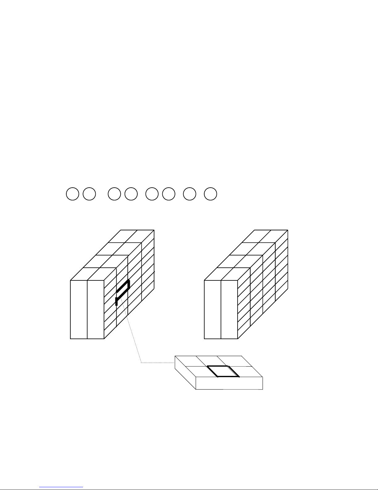
2.10 Shelf Location Limit Setting
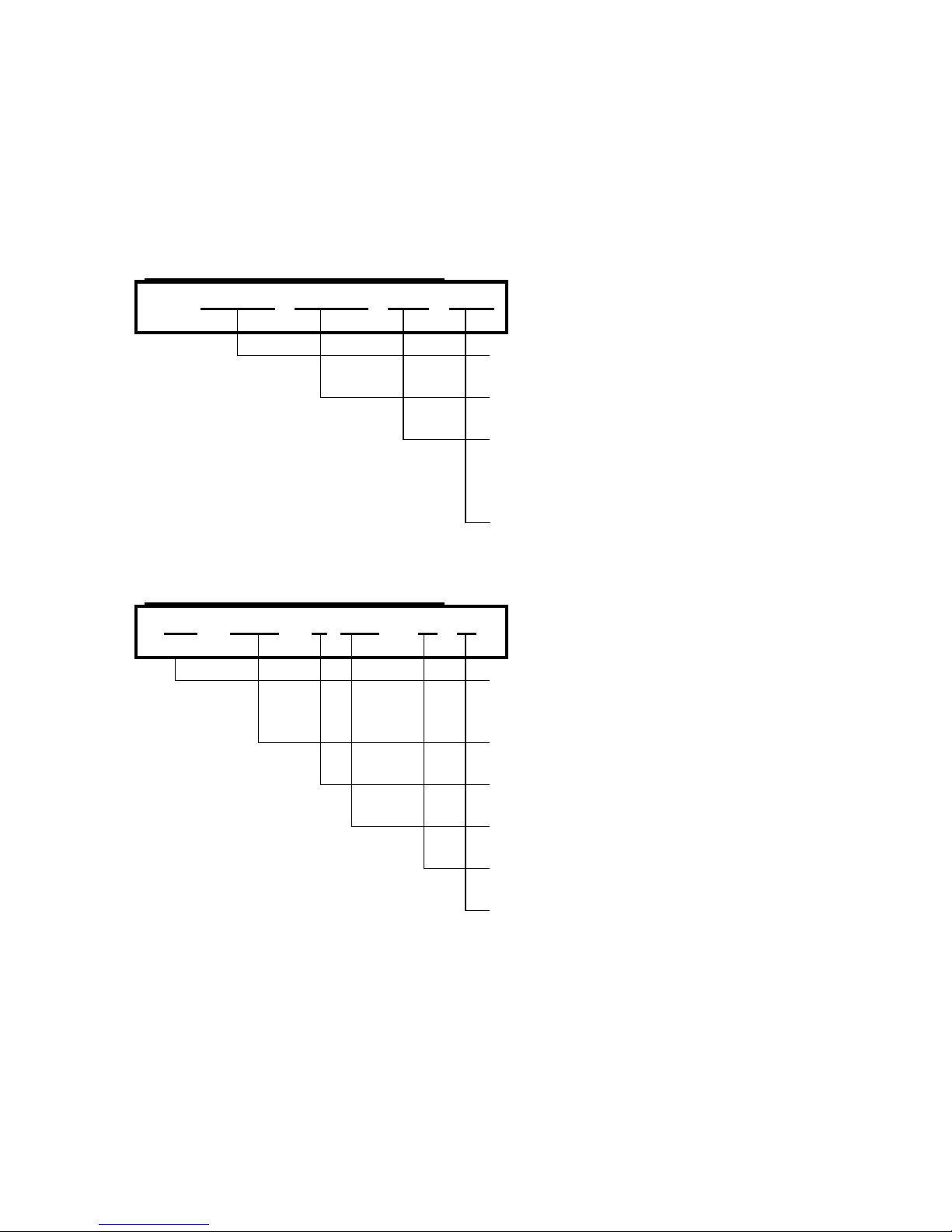
2.10a Genral Explanation for SHELF LOCATION No.
The shelf location number for each item can be programmed into DC-150 and can be
printed on tages for each shelf location. (Refer to 2.2 ID code setting.)
The location of parts can be discriminated by 8 digits. The first 2 digits are to be fiexed
for scale no. (The first 2 digits are printed on reports as scale no.)
The remaining 6 digits identify the following;
0 1 - 0 2 - 0 2 - 5 - E
SCALE - ROW - RACK - SHELF - BIN
1 2 3 4
A B C
D E F
Note: 1) The same shelf location number cannot be assigned in any other part.
Page 65

64
2.10b Shelf Location Limit
The maximum available character or number for each digit of shelf location number can
be set, according to your definition and the stock room.
By setting up the maximum limit of each digits which are composed of shelf location
number, when you miss-set the shelf location data which dose not exsit in your
definition, the erroe buzzer notice the miss-entry and the incalid data cannot be entered
in the momoey of ID data.
Programmable character and the available characters
Programmable
characters
available characters for a set
0 0
1 0, 1
9 0, 1, 2, 3, 4, 5 , 6, 7, 8, 9
A
0, 1, 2, 3, 4, 5, 6, 7, 8 , 9, A
Z 0, 1, 2, 3, 4, 5, 6, 7, 8 , 9, A ~ Z
2.10c Programming Operation
1. Enter Program Mode and select SHELF
LOCATION LIMIT.
PRG : S. LOCATION LABEL
. . . . . . . . . . . . . . . . . . . .
Z S N K 1 2 3 I R M I O 1 2 3 4 5 6 7 8
2. Depress [ENTER] key.
LIMIT = 00 - 00 - 00 - 0 - 0
. . . . . . . . . . . . . . . . . . . .
Z S N K 1 2 3 I R M I O 1 2 3 4 5 6 7 8
3. Enter the data with numeric keys.
Ex.) 01-15-09-A-Z
LIMIT = 0 1 1 5 0 9 A Z
. . . . . . . . . . . . . . . . . . . .
Z S N K 1 2 3 I R M I O 1 2 3 4 5 6 7 8
4. Depress [ENTER] key to store the data.
PRG : S. LOCATION LABEL
. . . . . . . . . . . . . . . . . . . .
Z S N K 1 2 3 I R M I O 1 2 3 4 5 6 7 8
Page 66

65
2.11 Address Contents Setting
Address data can be printed on a label which have printing area for address contents.
The data can be called in Operation Mode from the different data base from ID coode.
Address Contents can be programmed up to 10 (files) patterns. Also, the data base of
one file has 5 lines (32 characters/line) You can select address file no. on calling ID
code in OPR mode.
2.11a Programming Operation
1. Enter Program Mode and select Address
Contents.
PRG : ADDRESS CONTENTS
. . . . . . . . . . . . . . . . . . . .
Z S N K 1 2 3 I R M I O 1 2 3 4 5 6 7 8
2. Depress [ENTER] key.
A.C = FILE NO. 1
♦♦♦♦
. . . . . . . . . . . . . . . . . . . .
Z S N K 1 2 3 I R M I O 1 2 3 4 5 6 7 8
♦ = Blinking Cursor
3. Select file no. by pressing [ + ] or [ - ] key.
Ex.) File No. = 3
A.C = FILE NO. 3
♦♦♦♦
. . . . . . . . . . . . . . . . . . . .
Z S N K 1 2 3 I R M I O 1 2 3 4 5 6 7 8
♦ = Blinking Cursor
4. Press [ENTER] key.
F3 = ADDRESS NO. 1
♦♦♦♦
. . . . . . . . . . . . . . . . . . . .
Z S N K 1 2 3 I R M I O 1 2 3 4 5 6 7 8
♦ = Blinking Cursor
5. Select address no. by pressing [ + ] or [ - ]
key. Ex.) Address no. = 1
F3 = ADDRESS NO. 1
♦♦♦♦
. . . . . . . . . . . . . . . . . . . .
Z S N K 1 2 3 I R M I O 1 2 3 4 5 6 7 8
6. Press [ENTER] key.
3.1 =
. . . . . . . . . . . . . . . . . . . .
Z S N K 1 2 3 I R M I O 1 2 3 4 5 6 7 8
Page 67
66
7. Enter the data.
Ex.) 13-12 Kugahara 5-Chome Ohta-ku
3.1=
. . . . . . . . . . . . . . . . . . . .
Z S N K 1 2 3 I R M I O 1 2 3 4 5 6 7 8
8. Enter the data.
Ex.) TERAOKA SEIKO CO., LTD.
(23) O K A S E I K O C O . , L T D
. . . . . . . . . . . . . . . . . . . .
Z S N K 1 2 3 I R M I O 1 2 3 4 5 6 7 8
9. Press [ENTER] key.
F3 = ADDRESS NO. 1
♦♦♦♦
. . . . . . . . . . . . . . . . . . . .
Z S N K 1 2 3 I R M I O 1 2 3 4 5 6 7 8
♦ = Blinking Cursor
10. Select address no. by pressing [ + ] or [ - ]
key. Ex.) Address no. = 2
F3 = ADDRESS NO. 2
♦♦♦♦
. . . . . . . . . . . . . . . . . . . .
Z S N K 1 2 3 I R M I O 1 2 3 4 5 6 7 8
♦ = Blinking Cursor
Program address data with the same procedure as above.
11. Enter the data into memory file.
F3 = ADDRESS NO. 1
♦♦♦♦
. . . . . . . . . . . . . . . . . . . .
Z S N K 1 2 3 I R M I O 1 2 3 4 5 6 7 8
12. Press [ENTER] key.
A.C = FILE NO. 1
♦♦♦♦
. . . . . . . . . . . . . . . . . . . .
Z S N K 1 2 3 I R M I O 1 2 3 4 5 6 7 8
Page 68

67
2.6b Delete Pre-Print Contents Data
1. Enter Program Mode and select Address
Contents.
PRG : ADDRESS CONTENTS
. . . . . . . . . . . . . . . . . . . .
Z S N K 1 2 3 I R M I O 1 2 3 4 5 6 7 8
2. Depress [ENTER] key.
A.C = FILE NO. 1
♦♦♦♦
. . . . . . . . . . . . . . . . . . . .
Z S N K 1 2 3 I R M I O 1 2 3 4 5 6 7 8
♦ = Blinking Cursor
3. Select file no. by pressing [ + ] or [ - ] key.
Ex.) File No. = 3
A.C = FILE NO. 3
♦♦♦♦
. . . . . . . . . . . . . . . . . . . .
Z S N K 1 2 3 I R M I O 1 2 3 4 5 6 7 8
♦ = Blinking Cursor
4. Press [ENTER] key.
F3 = ADDRESS NO. 1
♦♦♦♦
. . . . . . . . . . . . . . . . . . . .
Z S N K 1 2 3 I R M I O 1 2 3 4 5 6 7 8
♦ = Blinking Cursor
5. Select address no. by pressing [ + ] or [ - ]
key. Ex.) Address no. = 1
F3 = ADDRESS NO. 1
♦♦♦♦
. . . . . . . . . . . . . . . . . . . .
Z S N K 1 2 3 I R M I O 1 2 3 4 5 6 7 8
6. Enter the data.
(23) T E R A O K A S E I K O C O
. . . . . . . . . . . . . . . . . . . .
Z S N K 1 2 3 I R M I O 1 2 3 4 5 6 7 8
7. Depres [CLEAR] key to enter the deletion
screen.
DEL T E R A O K A S E I K O C O
. . . . . . . . . . . . . . . . . . . .
Z S N K 1 2 3 I R M I O 1 2 3 4 5 6 7 8
8. Depress [Y] to delete data. * 1
C2=
. . . . . . . . . . . . . . . . . . . .
Z S N K 1 2 3 I R M I O 1 2 3 4 5 6 7 8
Note: *1) To escape from the deletion screen, press [N] key.
Page 69

68
3. MAINTENANCE MODE
Page 70

69
3.1 GENERAL INFORMATION--------------------------------71
3.1a How To Enter Maintenance Mode------------------------------------------ 71
3.1b Key Function In Maintenance Mode---------------------------------------
72
3.2 METHOD PROGRAM --------------------------------------73
3.2a Programming Screen for Specification Setting-------------------------- 73
3.2b Programming SPECs----------------------------------------------------------
73
3.3 MEMORY DELETE------------------------------------------92
3.3a Deleting Memory File---------------------------------------------------------- 93
3.4 PRINT ADJUSTMENT--------------------------------------94
3.4a Feed Value Program----------------------------------------------------------- 94
3.4b Detection Level Programming-----------------------------------------------
95
3.4c Print Contrast Program--------------------------------------------------------
96
3.5 AUTO JOB OPERATION PROGRAM------------------99
3.5a Programmable task ------------------------------------------------------------ 99
3.5b Default Setting ------------------------------------------------------------------
99
3.5c Programming Screen for Task Order-------------------------------------
100
3.5d Programming Task Order ---------------------------------------------------
100
3.6 FL-1 COMMUNICATION--------------------------------- 102
3.6a Data Back up -------------------------------------------------------------------102
Page 71

70
3.7 MODEM COMMUNICATION --------------------------- 103
3.7a Data Transmission Procedure (Access Side) --------------------------103
3.7b Data Transmission Procedure (Awaiting Side)-------------------------
106
3.8 SPEC LIST PRINTING ----------------------------------- 107
Page 72

71
3.1 General Information
3.1a How To Enter Maintenance Mode
When powered on, the scale always gets into Operation Mode.
WEIGHT UNIT WEIGHT QUANTITY
0 . 0 0 0 . 0
∇ ∇ ∇ ∇ ∇
• • • • • • • • • • • • • • • • • • • •
ZERO NET 1 2 3 RECO IN OUT 1 2 3 4 5 6 7 8
(SCALE) JOB MODULE
STABLE KG INSUFF MEMORY
1. Change to Maintenance mode by
depressing [MODE] key.
MAINTENANCE MODE
. . . . . . . . . . . . . . . . . . . .
Z S N K 1 2 3 I R M I O 1 2 3 4 5 6 7
8
2. Enter Maintenance mode by depressing
[ENTER] key.
MEN: METHOD PROGRAM
. . . . . . . . . . . . . . . . . . . .
Z S N K 1 2 3 I R M I O 1 2 3 4 5 6 7
8
3. Select each file in Maintenance Mode by
depressing [TARE←] or [UNIT WEIGHT→] key.
MEN: MEMORY DELETE
. . . . . . . . . . . . . . . . . . . .
Z S N K 1 2 3 I R M I O 1 2 3 4 5 6 7
8
4. Enter the displayed mode by depressing
[ENTER] key
DEL = ALL MEMORY
. . . . . . . . . . . . . . . . . . . .
Z S N K 1 2 3 I R M I O 1 2 3 4 5 6 7
8
Note) Each file is changed in loop routine with [TARE←] or [UNIT WEIGHT→] key.
Page 73

72
3.1b Key Function In Maintenance Mode
[MODE] Key
To return to the initial screen of each modes without saving programmed data.
[AUTO/MANUAL] key
To return to the previous screen in programming.
[ENTER] key
To enter the next screen in each file.
To enter the programmed data into memory file.
Execute the data transaction.
Print SPEC report.
[TARE (←)] and [UNIT WEIGHT (→)] key
Select the headings in loop routines.
Move the cursor to left/right when there are purl cursors in a display.
[PLUS +] and [MINUS -] key
To select the data, when cursor of triangle indicator is blinking.
CURSORS
The cursors appear when setting data. The cursor shows not only the maximum
number of digits, but also the characteristic of the entering data.
1.) Light cursor ..... The numeric data should be entered with numeric keys.
2.) Blinking cursor .... The data should be selected with [ + ] or [ − ] key
Page 74

73
3.2 Method Program
You can set up the various specifications of scale. By the functions of the SPECs,
these are divided into 4 groups, DISPLAY, REPORT, PRINT, OUTSIDE APPARATUS,
and OTHERS.
3.2a Programming Screen for Specification Setting
00 : ITEM / PART NO. = Y
♦♦ ♦
ADDRESS NO.
Depress [+] key to go forth.
Depress [-] key to go back.
CLAUSE OF SPEC
SELECTION ITEM
Make selection with [+] or [-]
keys.
Note) [TARE] or [UNITE WEIGHT] keys work for moving cursor.
Note) [ENTER] key works for entering the data into the memory.
3.2b Programming SPECs
1. Enter Maintenance mode by depressing
[ENTER] key.
MEN: METHOD PROGRAM
. . . . . . . . . . . . . . . . . . . .
Z S N K 1 2 3 I R M I O 1 2 3 4 5 6 7
8
2. Enter Method Program by depressing
[ENTER] key.
MTP=DISPLAY
. . . . . . . . . . . . . . . . . . . .
Z S N K 1 2 3 I R M I O 1 2 3 4 5 6 7
8
Page 75

74
3. Select a group of the SPECs by pressing
[TARE←] or [UNIT WEIGHT→] keys.
MTP= REPORT
. . . . . . . . . . . . . . . . . . . .
Z S N K 1 2 3 I R M I O 1 2 3 4 5 6 7
8
4. Depress [ENTER] key.
0 : ITM/ CONTENT = Y
♦
. . . . . . . . . . . . . . . . . . . .
Z S N K 1 2 3 I R M I O 1 2 3 4 5 6 7
8
5. Change the SPEC address by depressing
[+] key 6 times.
06 : ITM /THRESHOLD = Y
♦♦
. . . . . . . . . . . . . . . . . . . .
Z S N K 1 2 3 I R M I O 1 2 3 4 5 6 7
8
6. Move the cursor by depressing
[UNIT WEIGHT→] key.
06 : ITM /THRESHOLD = Y
♦
. . . . . . . . . . . . . . . . . . . .
Z S N K 1 2 3 I R M I O 1 2 3 4 5 6 7
8
7. Change the SPEC by depressing [+] key.
6 : ITM /THRESHOLD = N
♦
. . . . . . . . . . . . . . . . . . . .
Z S N K 1 2 3 I R M I O 1 2 3 4 5 6 7
8
8. Enter the data to Memory by pressing
[ENTER] key.
7 : ITM /OUT = N
♦
(Ready for entering the next address.)
. . . . . . . . . . . . . . . . . . . .
Z S N K 1 2 3 I R M I O 1 2 3 4 5 6 7
8
Note) After you change all the SPECs, depress [AUTO/MANUAL] key to escape the
programming screen of SPECs.
Note) OUTSIDE APPARATUS SPEC is divided into scanner, force balance, RS-232C,
PC communication, MODEM communication and others. You can select each
SPECs with [UNIT WEIGHT←] and [TARE→] keys.
Page 76

75
DISPLAY SPECS
SPEC 00: Cancellation of Sub Total Display
(This SPEC actives only when SPEC 22 of PRINT is set to “NO”)
AUTO:
Auto Cancellation
MANUAL:
Manual Cancellation
REPORT SPECS
SPEC 00: Print Items in Item Report
ALL:
All Items
SELECT:
Selected Items
SPEC 01: Print Parts No. on Item Report
(This SPEC actives only when SPEC 00 of REPORT SPEC is set to “SELECT”)
Y:
Allow
N:
Inhibit
SPEC 02: Print Parts Name on Item Report
(This SPEC actives only when SPEC 00 of REPORT SPEC is set to “SELECT”)
Y:
Allow
N:
Inhibit
SPEC 03: Print Unit Weight on Item Report
(This SPEC actives only when SPEC 00 of REPORT SPEC is set to “SELECT”)
Y:
Allow
N:
Inhibit
SPEC 04: Print Shelf Location no. on Item Report
(This SPEC actives only when SPEC 00 of REPORT SPEC is set to “SELECT”)
Y:
Allow
N:
Inhibit
SPEC 05: Print Inventory on Item Report
(This SPEC actives only when SPEC 00 of REPORT SPEC is set to “SELECT”)
Y:
Allow
N:
Inhibit
Page 77

76
SPEC 06: Print Threshold on Item Report
(This SPEC actives only when SPEC 00 of REPORT SPEC is set to “SELECT”)
Y:
Allow
N:
Inhibit
SPEC 07: Print Out-Count (shipping) on Item Report
(This SPEC actives only when SPEC 00 of REPORT SPEC is set to “SELECT”)
Y:
Allow
N:
Inhibit
SPEC 08: Print In-Count (Receiving) on Item Report
(This SPEC actives only when SPEC 00 of REPORT SPEC is set to “SELECT”)
Y:
Allow
N:
Inhibit
SPEC 09: Print Tare Weight on Item Report
(This SPEC actives only when SPEC 00 of REPORT SPEC is set to “SELECT”)
Y:
Allow
N:
Inhibit
SPEC 10: Print Set Point on Item Report
(This SPEC actives only when SPEC 00 of REPORT SPEC is set to “SELECT”)
Y:
Allow
N:
Inhibit
SPEC 11: Print Selected scale no. on Item Report
(This SPEC actives only when SPEC 00 of REPORT SPEC is set to “SELECT”)
Y:
Allow
N:
Inhibit
SPEC 12: Print Auto Job No. for shipping operation on Item Report
(This SPEC actives only when SPEC 00 of REPORT SPEC is set to “SELECT”)
Y:
Allow
N:
Inhibit
SPEC 13: Print Auto Job No. for receiving operation on Item Report
(This SPEC actives only when SPEC 00 of REPORT SPEC is set to “SELECT”)
Y:
Allow
N:
Inhibit
Page 78

77
SPEC 14: Print Auto Job No. for Non-add operation on Item Report
(This SPEC actives only when SPEC 00 of REPORT SPEC is set to “SELECT”)
Y:
Allow
N:
Inhibit
SPEC 15: Print Items in Today’s Movement Report
ALL:
All Items
SELECT:
Selected Items
SPEC 16: Print Parts No. on Today’s Movement Report
(This SPEC actives only when SPEC 15 of REPORT SPEC is set to “SELECT”)
Y:
Allow
N:
Inhibit
SPEC 17: Print Parts Name on Today’s Movement Report
(This SPEC actives only when SPEC 15 of REPORT SPEC is set to “SELECT”)
Y:
Allow
N:
Inhibit
SPEC 18: Print Unit Weight on Today’s Movement Report
(This SPEC actives only when SPEC 15 of REPORT SPEC is set to “SELECT”)
Y:
Allow
N:
Inhibit
SPEC 19: Print Shelf Location no. on Today’s Movement Report
(This SPEC actives only when SPEC 15 of REPORT SPEC is set to “SELECT”)
Y:
Allow
N:
Inhibit
SPEC 20: Print Inventory on Today’s Movement Report
(This SPEC actives only when SPEC 15 of REPORT SPEC is set to “SELECT”)
Y:
Allow
N:
Inhibit
SPEC 21: Print Threshold on Today’s Movement Report
(This SPEC actives only when SPEC 15 of REPORT SPEC is set to “SELECT”)
Y:
Allow
N:
Inhibit
Page 79

78
SPEC 22: Print Out-Count (shipping) on Today’s Movement Report
(This SPEC actives only when SPEC 00 of REPORT SPEC is set to “SELECT”)
Y:
Allow
N:
Inhibit
SPEC 23: Print In-Count (Receiving) on Today’s Movement Report
(This SPEC actives only when SPEC 15 of REPORT SPEC is set to “SELECT”)
Y:
Allow
N:
Inhibit
SPEC 24: Print Tare Weight on Today’s Movement Report
(This SPEC actives only when SPEC 15 of REPORT SPEC is set to “SELECT”)
Y:
Allow
N:
Inhibit
SPEC 25: Print Set Point on Today’s Movement Report
(This SPEC actives only when SPEC 15 of REPORT SPEC is set to “SELECT”)
Y:
Allow
N:
Inhibit
SPEC 26: Print Selected scale no. on Today’s Movement Report
(This SPEC actives only when SPEC 15 of REPORT SPEC is set to “SELECT”)
Y:
Allow
N:
Inhibit
SPEC 27: Print Auto Job No. for shipping operation on Today’s Movement Report
(This SPEC actives only when SPEC 15 of REPORT SPEC is set to “SELECT”)
Y:
Allow
N:
Inhibit
SPEC 28: Print Auto Job No. for receiving operation on Today’s Movement Report
(This SPEC actives only when SPEC 15 of REPORT SPEC is set to “SELECT”)
Y:
Allow
N:
Inhibit
SPEC 29: Print Auto Job No. for Non-add operation on Today’s Movement Report
(This SPEC actives only when SPEC 15 of REPORT SPEC is set to “SELECT”)
Y:
Allow
N:
Inhibit
Page 80

79
SPEC 30: Print Items in Threshold Report
ALL:
All Items
SELECT:
Selected Items
SPEC 31: Print Parts No. on Threshold Report
(This SPEC actives only when SPEC 30 of REPORT SPEC is set to “SELECT”)
Y:
Allow
N:
Inhibit
SPEC 32: Print Parts Name on Threshold Report
(This SPEC actives only when SPEC 30 of REPORT SPEC is set to “SELECT”)
Y:
Allow
N:
Inhibit
SPEC 33: Print Unit Weight on Threshold Report
(This SPEC actives only when SPEC 30 of REPORT SPEC is set to “SELECT”)
Y:
Allow
N:
Inhibit
SPEC 34: Print Shelf Location no. on Threshold Report
(This SPEC actives only when SPEC 30 of REPORT SPEC is set to “SELECT”)
Y:
Allow
N:
Inhibit
SPEC 35: Print Inventory on Threshold Report
(This SPEC actives only when SPEC 30 of REPORT SPEC is set to “SELECT”)
Y:
Allow
N:
Inhibit
SPEC 36: Print Threshold on Threshold Report
(This SPEC actives only when SPEC 30 of REPORT SPEC is set to “SELECT”)
Y:
Allow
N:
Inhibit
SPEC 37: Print Out-Count (shipping) on Threshold Report
(This SPEC actives only when SPEC 30 of REPORT SPEC is set to “SELECT”)
Y:
Allow
N:
Inhibit
Page 81

80
SPEC 38: Print In-Count (Receiving) on Threshold Report
(This SPEC actives only when SPEC 30 of REPORT SPEC is set to “SELECT”)
Y:
Allow
N:
Inhibit
SPEC 39: Print Tare Weight on Threshold Report
(This SPEC actives only when SPEC 30 of REPORT SPEC is set to “SELECT”)
Y:
Allow
N:
Inhibit
SPEC 40: Print Set Point on Threshold Report
(This SPEC actives only when SPEC 30 of REPORT SPEC is set to “SELECT”)
Y:
Allow
N:
Inhibit
SPEC 41: Print Selected scale no. on Threshold Report
(This SPEC actives only when SPEC 30 of REPORT SPEC is set to “SELECT”)
Y:
Allow
N:
Inhibit
SPEC 42: Print Auto Job No. for shipping operation on Threshold Report
(This SPEC actives only when SPEC 30 of REPORT SPEC is set to “SELECT”)
Y:
Allow
N:
Inhibit
SPEC 43: Print Auto Job No. for receiving operation on Threshold Report
(This SPEC actives only when SPEC 30 of REPORT SPEC is set to “SELECT”)
Y:
Allow
N:
Inhibit
SPEC 44: Print Auto Job No. for Non-add operation on Threshold Report
(This SPEC actives only when SPEC 30 of REPORT SPEC is set to “SELECT”)
Y:
Allow
N:
Inhibit
Page 82

81
PRINT SPECS
SPEC 00: Print Bar-code of ID code
Y :
Allow
N :
Inhibit
SPEC 01: The first digit of ID code data on bar-code
0 L ~ 16L
0L ~ 16 L
SPEC 02: The last digit of ID code data on bar-code
0L ~ 16L
0L ~ 16 L
SPEC 03: Print Human readable number under bar-code (ID code)
Y:
Allow
N:
Inhibit
SPEC 04: Print Bar-code of Parts No.
Y:
Allow
N:
Inhibit
SPEC 05: The first digit of Parts No. data on bar-code
0L ~ 16L
0L ~ 16L
SPEC 06: The last digit of Parts No. data on bar-code
0L ~ 16L
0L ~ 16L
SPEC 07: Print Human readable number under bar-code (Parts No.)
Y:
Allow
N:
Inhibit
SPEC 08: Print bar-code of lot no.
Y:
Allow
N:
Inhibit
Page 83

82
SPEC 09: The first digit of Lot No. data on bar-code
0L ~ 16L
0L ~ 16L
SPEC 10: The last digit of Lot No. data on bar-code
0L ~ 16L
0L ~ 16L
SPEC 11: Print Human readable number under bar-code (Lot No.)
Y:
Allow
N:
Inhibit
SPEC 12: Print bar-code of quantity
Y:
Allow
N:
Inhibit
SPEC 13: Print Human Readable number under bar-code (Q’ty)
Y:
Allow
N:
Inhibit
SPEC 14: Print bar-code of unit weight
Y:
Allow
N:
Inhibit
SPEC 15: Print Human Readable number under bar-code (Unit Weight)
ALL:
All Items
SELECT:
Selected Items
SPEC 16: Print bar-code of tare
Y:
Allow
N:
Inhibit
Page 84

83
SPEC 17: Print Human Readable number under bar-code (Tare Weight)
Y:
Allow
N:
Inhibit
SPEC 18: Print bar-code of gross weight
Y:
Allow
N:
Inhibit
SPEC 19: Print Human Readable number under bar-code (gross weight)
Y:
Allow
N:
Inhibit
SPEC 20: Print bar-code of net weight
Y:
Allow
N:
Inhibit
SPEC 21: Print Human Readable number under bar-code (net weight)
Y:
Allow
N:
Inhibit
SPEC 22: Label Print
ALL
All operation
OUT
Shipping Operation
IN
Receiving Operation
N/A
Non-add Operation
I&O
Receiving and Shipping Operations
NON
No Printing
SPEC 23: Print Title of task
Y:
Allow
N:
Inhibit
Page 85

84
SPEC 24: Print Pre-print data
Y:
Allow
N:
Inhibit
SPEC 25: Print quantity symbol
PCS:
Pcs
M:
m
CM:
cm
NONE:
No Print
SPEC 26: Print “/” for weight when weight is 0.
Y:
Allow
N:
Inhibit
SPEC 27: Width of receipt paper
66MM:
66mm
40MM:
40mm
SPEC 28: Type of sum total receipt issued in multiple transaction
LONG:
Long
SHORT
Short
SPEC 29: Print the current time
Y:
Allow
N:
Inhibit
SPEC 30: Print the current date
Y:
Allow
N:
Inhibit
SPEC 31: Free Format
Y:
Allow
N:
Inhibit
SPEC 32: Free Format No.
Page 86

85
No.1
No.1
No.2
No.2
SPEC 33: Standard Format No.
No.1 ~ No.7
No.1 ~ No.7
SPEC 34: Label Size of Free Format
40 x 28, 40 x 46, 40 x 62.5, 40 x 77.5, 40 x 92, 64 x 40, 64 x 55, 64 x 77.5, 64 x 92,
64 x 120
SPEC 35: Type of bar-code
CODE39:
Code 39
UPC-A:
UPC-A
SPEC 36: Type of UPC bar-code
13
13 Digits
8
8 Digits
SPEC 37: Number system character (NS) of UPC bar-code
0 ~ 9 :
0 ~ 9
SPEC 38: Print header code on bar-code (Code 39 only)
Y:
Allow
N:
Inhibit
SPEC 39: Feed label after printing the last label in continuous printing
Y:
Allow
N:
Inhibit
Page 87

86
OUTSIDE APPARATUS SPECS
SCANNER
SPEC 00: Scanner Connection
CONNECT
Connected
NOT
Not Connected
SPEC 01: Type of Scanner
WAND:
Wand Type
PEN:
Pen Type
SPEC 02: Communication level (Interface) for scanner connection
TTL:
TTL Serial
232C:
RS-232C
SPEC 03: Bit Length (Scanner)
7:
7 bit
8:
8 bit
SPEC 04: Parity bit (Scanner)
NONE:
None
ODD:
Odd
EVEN:
Even
SPEC 05: Bit Length (Scanner)
1200, 2400, 4800, 9600, 19200
SPEC 06: Stop Bit (Scanner)
1:
1 bit
2:
2 bit
SPEC 07: Refer to scanning data as ID code
Y:
Allow
N:
Inhibit
SPEC 08: Ignore spaces in bar-code (SPACE DATA)
Page 88

87
Y:
Allow
N:
Inhibit
FORCE BALANCE SPEC
SPEC 00: DATA INPUT FROM F/B
I.COUNT
Internal Count
WEIGHT
Weight data
SPEC 01: Bit Length (F/B)
7:
7 bit
8:
8 bit
SPEC 02: Parity bit (F/B)
NONE:
None
ODD:
Odd
NONE:
None
SPEC 03: Communication Speed (F/B)
2400:
2400 BPS
4800:
4800 BPS
9600:
SPEC 04: STOP BIT (F/B)
1:
1
2:
2
Page 89

88
RS-232C SPEC
SPEC 00: Bit Length (RS232)
7:
7 bit
8:
8 bit
SPEC 01: Parity bit (RS-232)
NONE:
None
ODD:
Odd
EVEN:
Even
SPEC 02: Communication Speed (RS-232)
1200:
1200 BPS
2400:
2400 BPS
4800:
4800 BPS
9600:
9600 BPS
19200:
19200 BPS
SPEC 03: STOP BIT (RS-232)
1:
1
2:
2
SPEC 04: Timing of RS-232C Output
NOT:
No Output
CA.:
by calculation
[ * ]:
by [ENTER] key
C/*:
by calculation and [ENTER] key.
SPEC 05: RS-232C INPUT
Y:
Allow
N:
Inhibit
SPEC 06: RS-232C input field delimiter
CR:
Carriage Feed
LF:
Line Feed
Page 90

89
MODEM SPEC
SPEC 00: Connection of MODEM
NOT:
Not connected
CONNECT:
Connected
SPEC 01: Dial type of telephone
PULSE:
Pulse dial
TONE:
Tone dial
OTHER SPEC
SPEC 00: Read Header data on bar-code
Y:
Allow
N:
Inhibit
SPEC 01: Connection of IBM Keyboard
NOT:
Not connected
CONNECT:
Connected
Page 91

90
OTHER SPECS
SPEC 00: Set Point Function
NONE:
Inhibit
ALL
In all items
E-CODE
In ID Items
N-CODE
In Non-ID Items
SPEC 01: Type of Set point function
RESULT%:
Quantity & %
RES.MIN&MAX:
Minimum Quantity & Maximum Quantity
WEIGHT%:
Weight & %
WT.MIN&MAX
Minimum Weight & Maximum Weight
RECOMP.COU%
Quantity & % after recomputing Unit Weight
SPEC 02: Keep Lot No.
Y:
Allow
N:
Inhibit
SPEC 03: Renew the inventory data when counting item in Non-add Operation
Y:
Allow
N:
Inhibit
SPEC 04: Auto Job No. for a whole Items (shipping)
PAT1~5
Pattern 1 ~ Pattern 5
SPEC 05: Auto Job No. for a whole Items (receiving)
PAT1~5
Pattern 1 ~ Pattern 5
SPEC 06: Auto Job No. for a whole Items (Non-add)
PAT1~5
Pattern 1 ~ Pattern 5
SPEC 07: Prohibit to use Power Save Function
Y:
Allow
N:
Inhibit
Page 92

91
SPEC 08: Prohibit to enter CHECK Mode.
Y:
Allow
N:
Inhibit
SPEC 09: Prohibit to enter PROGRAM Mode.
Y:
Allow
N:
Inhibit
SPEC 10: Prohibit to enter MAINTENANCE Mode.
Y:
Allow
N:
Inhibit
SPEC 11: Warn when operation will result in an inventory less than threshold level.
Y:
Allow
N:
Inhibit
SPEC 12: Date Format
D/M/Y:
DD/MM/YY
M/D/Y
MM/DD/YY
Y/M/D
YY/MM/DD
SPEC 13: Calling ID code in Auto Job Operation
Y:
Allow
N:
Inhibit
SPEC 14: Prohibit to count Non-ID code Item
Y:
Allow
N:
Inhibit
SPEC 15: Memory Size
385:
385 Items
3080:
3,080 Items
Page 93

92
3.3 Memory Delete
The deletion of the programmed data can be executed by each file collectively. All or a
part of file to delete can be selected as showing in the following table.
INDEX MEMORY FILES TO DELETE
ALL ITEM FILE All Item File
ITEM MEMORY FILE PART NO. Part no. data of all items
PART NAME Part name data of all items
UNIT WEIGHT Unit weight of all items
SHELF LOCATION NO. Shelf location no. of all items
INVENTORY Inventory data of all items
THRESHOLD Threshold data of all items
DAILY OUT-COUNT Today’s shipping record of all
items
DAILY IN-COUNT Today’s receiving record of all
items
TARE VALUE Tare values of all items
SET POINT VALUE Set point values of all items
SELECTED SCALE NO. Selected scale no. of all items
AUTO JOB NO. FOR
SHIPPING OPERATION
Auto job no for shipping operation
of all items
AUTO JOB NO. FOR
RECEIVING
OPERATION
Auto job no. for receiving
operation of all items
AUTO JOB NO. FOR
COUNTING OPERATION
Auto job no. for counting operation
of all items
PRINT FORMAT FILE PRINT FORMAT Free format, pre-print, S. location
label , Title contents
SEQ NO. SEQ NO.
Page 94

93
3.3a Deleting Memory File
1. Select Memory Delete Mode in Maintenance
Mode by depressing
MEN: MEMORY DELETE
[TARE←] or [U.W→] keys.
. . . . . . . . . . . . . . . . . . . .
Z S N K 1 2 3 I R M I O 1 2 3 4 5 6 7
8
2. Enter Memory Delete Mode by depressing
[ENTER]key.
DEL ALL ITEM MEMORY
. . . . . . . . . . . . . . . . . . . .
Z S N K 1 2 3 I R M I O 1 2 3 4 5 6 7
8
3. Select the memory file to delete by
depressing[TARE←] or [U.W→] keys.
DEL = ITEM MEMORY
Ex) ITEM MEMORY FILE
. . . . . . . . . . . . . . . . . . . .
Z S N K 1 2 3 I R M I O 1 2 3 4 5 6 7
8
4. Depress [ENTER] key.
ITM = PART NO.
. . . . . . . . . . . . . . . . . . . .
Z S N K 1 2 3 I R M I O 1 2 3 4 5 6 7
8
5. Select Item Data to delete by
depressing[TARE←] or [U.W→] keys.
ITM = INVENTORY
Ex) INVENTORY Data
. . . . . . . . . . . . . . . . . . . .
Z S N K 1 2 3 I R M I O 1 2 3 4 5 6 7
8
6. Press [ENTER] key.
INVENTRY DEL ? Y / N
. . . . . . . . . . . . . . . . . . . .
Z S N K 1 2 3 I R M I O 1 2 3 4 5 6 7
8
7. Depress [Y] key to delete the data.
[N] key works to escape the deletion mode.
DEL = ITEM MEMORY
. . . . . . . . . . . . . . . . . . . .
Z S N K 1 2 3 I R M I O 1 2 3 4 5 6 7
8
Page 95

94
3.4 Print Adjustment
These options in this mode may control print performance. In most cases, these values
will not be needed to be changed at customer side.
Print performance can be controlled by setting Feed Value, Level of Detection, and Print
Contrast.
3.4a Feed Value Program
This measurement is factory set to 0, if the correct label size are set at PRINT SPEC.
However, if the print position is not proper, use this option to adjust the label present to
the proper value for printing.
F E E D V A L U E =
0
♦ ♦ ♦ ♦
• • • • • • • • • • • • • • • • • • • •
Z S T K 1 2 3 I R M I O 1 2 3 4 5 6 7
8
Key Functions : [ + ] key is used for the increment of the feed value. (Max = +127)
[ - ] key is used for the decrement of the feed value. (Max = -127)
[→ (feed )] key is used for feeding label to check the proper feed value.
Programming Feed Value
1. Select Print Adjustment Mode in
Maintenance Mode by depressing [TARE←]
MEN: PRINT ADJUSTMENT
or [U.W→] keys.
. . . . . . . . . . . . . . . . . . . .
Z S N K 1 2 3 I R M I O 1 2 3 4 5 6 7
8
2. Depress [ENTER] key.
ADJ = FEED VALUE
. . . . . . . . . . . . . . . . . . . .
Z S N K 1 2 3 I R M I O 1 2 3 4 5 6 7
8
3. Enter FEED VALUE setting Mode by
EED VALUE = 0
♦♦♦♦
Page 96

95
pressing [ENTER] key.
. . . . . . . . . . . . . . . . . . . .
Z S N K 1 2 3 I R M I O 1 2 3 4 5 6 7
8
4. Adjust the feed value with [ + ] and [ - ] key.
Ex) + 2
EED VALUE = + 2
♦♦♦♦
. . . . . . . . . . . . . . . . . . . .
Z S N K 1 2 3 I R M I O 1 2 3 4 5 6 7
8
5. Exit the FEED VALUE setting Mode by
pressing [AUTO/MANUAL] key.
ADJ = FEED VALUE
. . . . . . . . . . . . . . . . . . . .
Z S N K 1 2 3 I R M I O 1 2 3 4 5 6 7
8
3.4b Detection Level Programming
This option is to control the sensitivity of the gap sensor, which is used to locate the
space between labels. The value will be adjusted automatically on feeding label out.
If the sensor cannot detect the gap between labels, use this option to adjust the label
present to the proper value for printing.
LEVEL ( 2 8) = 0
♦ ♦ ♦ ♦
• • • • • • • • • • • • • • • • • • • •
Z S T K 1 2 3 I R M I O 1 2 3 4 5 6 7
8
Detection level
Key Functions : [ + ] key is used for the increment of detection level. (Max = +127)
[ - ] key is used for the decrement of detection level. (Max = -127)
[→ (feed )] key is used for feeding label to check the proper value.
Programming Detection Level
1. Select Print Adjustment Mode in
Maintenance Mode by depressing [TARE←]
MEN: PRINT ADJUSTMENT
or [U.W→] keys.
. . . . . . . . . . . . . . . . . . . .
Z S N K 1 2 3 I R M I O 1 2 3 4 5 6 7
Page 97

96
8
2. Depress [ENTER] key.
ADJ = FEED VALUE
. . . . . . . . . . . . . . . . . . . .
Z S N K 1 2 3 I R M I O 1 2 3 4 5 6 7
8
3. Select LABEL DETECTION Setting Mode
by pressing [TARE←] or [U.W→] keys
ADJ= DETECTION OF LEV
. . . . . . . . . . . . . . . . . . . .
Z S N K 1 2 3 I R M I O 1 2 3 4 5 6 7
8
4. Depress [ENTER] key.
LEVEL ( 7 ) = 0
♦♦♦♦
. . . . . . . . . . . . . . . . . . . .
Z S N K 1 2 3 I R M I O 1 2 3 4 5 6 7
8
5. Adjust the detection level with [ + ] and [ - ]
key. - 2
FEED VALUE = - 2
♦♦♦♦
. . . . . . . . . . . . . . . . . . . .
Z S N K 1 2 3 I R M I O 1 2 3 4 5 6 7
8
6. Exit the Print Adjustment setting Mode by
pressing [AUTO/MANUAL] key.
ADJ = FEED VALUE
. . . . . . . . . . . . . . . . . . . .
Z S N K 1 2 3 I R M I O 1 2 3 4 5 6 7
8
3.4c Print Contrast Program
This option is to control the heart of the thermal head when printing. The higher the
number, the hotter the head and the darker the print will be. This is set to 0 at factory
default. Since the thermal head may be damaged when setting higher value, we
recommend to set the value at the default setting.
CONTRAST =
0
♦ ♦ ♦ ♦
• • • • • • • • • • • • • • • • • • • •
Z S T K 1 2 3 I R M I O 1 2 3 4 5 6 7
8
Key Functions : [ + ] key is used for the increment of Contrast Value. (Max = +127)
Page 98

97
[ - ] key is used for the decrement of Contrast Value. (Max = -127)
[→ (feed )] key is used for feeding label to check the proper value.
Programming Detection Level
1. Select Print Adjustment Mode in
Maintenance Mode by depressing [TARE←]
MEN: PRINT ADJUSTMENT
or [U.W→] keys.
. . . . . . . . . . . . . . . . . . . .
Z S N K 1 2 3 I R M I O 1 2 3 4 5 6 7
8
2. Depress [ENTER] key.
ADJ = FEED VALUE
. . . . . . . . . . . . . . . . . . . .
Z S N K 1 2 3 I R M I O 1 2 3 4 5 6 7
8
3. Select PRINT CONTRAST Setting Mode by
pressing [TARE←] or [U.W→] keys
ADJ= PRINT CONTRAST
. . . . . . . . . . . . . . . . . . . .
Z S N K 1 2 3 I R M I O 1 2 3 4 5 6 7
8
4. Depress [ENTER] key.
ONTRAST = 0
♦♦♦♦
. . . . . . . . . . . . . . . . . . . .
Z S N K 1 2 3 I R M I O 1 2 3 4 5 6 7
8
5. Adjust the print contrast with [ + ] and [ - ]
key. Ex) +1
ONTRAST = +1
♦♦♦♦
. . . . . . . . . . . . . . . . . . . .
Z S N K 1 2 3 I R M I O 1 2 3 4 5 6 7
8
6. Exit the Print Adjustment setting Mode by
pressing [AUTO/MANUAL] key.
ADJ= PRINT CONTRAST
. . . . . . . . . . . . . . . . . . . .
Z S N K 1 2 3 I R M I O 1 2 3 4 5 6 7
8
Page 99

98
Page 100

99
3.5 Auto Job Operation Program
This function is to show operator the next task in counting operation. Operator can
complete the counting operation along with display indication with this function.
The remarkable merits of this function are;
• Operator can execute each task by pressing [ENTER] key.
• All operator can complete counting operation without skipping required tasks.
• Operation process can be programmed up to 5 patterns. And, a pattern can be
assigned to each of shipping, receiving, non-add operations of each ID code.
3.5a Programmable task
Ref. # Tasks
A Lot No. Entry by pressing Numeric keys or scanning.
B Parts No. Entry by pressing Alpha-numeric keys or scanning.
C Tare Entry by pressing Numeric keys, scanning, or one touch tare
D Unit Weight Entry by sampling.
E Unit Weight Entry by Pressing Numeric keys.
F Counting task.
G Quantity Entry by pressing Numeric keys.
H Label Printing.
I Escaping from Auto Job Operation Mode
J Back to the 1st task in Auto Job Operation.
3.5b Default Setting
Pattern No. Task Reference #.
A B C D E F G H I J
1
{ { { {
{
{
{
2
{ { { {
{ {
{
3
{
{ {
{
{
4
{ {
{ {
{
5
{ {
{ {
{
Note 1) The last step of each operations should be “I” or “J”
 Loading...