

Digi Connectware Digi CM 8, Connectware Digi CM 16, Connectware Digi CM 32, Connectware Digi CM 48 User Manual
Page 1

User Guide
Digi CM
90000301_E
Page 2

Page 3

Digi International Inc. 2004.
Digi, Digi International, the Digi logo, the Digi Connectware, the Making Device
Networking Easy logo, Digi One, and RealPort are trademarks or registered
trademarks of Digi International, Inc. in the United States and other countries
worldwide. All other trademarks are the property of their respective owners.
Microsoft Windows Server 2003 is a trademark of Microsoft Corporation.
Page 4

4
Page 5

Contents
Chapter 1 Introduction
Digi CM Model Support....................................................................................9
Feature Overview.............................................................................................9
Feature Summary.............................................................................................9
User Groups...................................................................................................11
Root and Admin Usernames and Passwords.................................................11
Adding Port Administrators and Users...........................................................11
Ways to Configure the Digi CM......................................................................11
Ways of Accessing the Digi CM: Overview....................................................13
Web Interface Access Menu..........................................................................13
Port Access Menu..........................................................................................15
Direct Port Access..........................................................................................15
Custom Menus...............................................................................................16
Port Escape Menu..........................................................................................16
Saving and Applying Changes.......................................................................19
Automatic Device Recognition.......................................................................19
Chapter 2 Getting Started
Introduction.....................................................................................................21
Assigning IP Settings from the Console Port.................................................21
Configuring HTTP and HTTPS.......................................................................22
Configuring for SSH.......................................................................................23
Adding, Editing, and Removing Users............................................................25
Chapter 3 Installing and Configuring PC Cards
Introduction.....................................................................................................27
Compatible PC Cards.....................................................................................27
Adding a Compact-flash Card........................................................................27
Adding a Network Card..................................................................................28
Adding a Wireless LAN Card..........................................................................29
Adding a Serial Modem..................................................................................30
Chapter 4 System and Port Logging
Introduction.....................................................................................................33
Enabling Log Storage Location......................................................................33
Configuring System Logging..........................................................................36
Configure Port Logging..................................................................................38
Chapter 5 Configuring Ports
Introduction.....................................................................................................41
Enabling and Disabling the Ports...................................................................41
Resetting Ports............................................................................................... 42
Port Title.........................................................................................................42
Contents 5
Page 6

Configuring Automatic Device Recognition....................................................42
Apply all Ports Settings ............................................................................... ...44
Host Mode Configuration................................................................................44
Configuring Host Mode...................................................................................47
Supported Protocols.......................................................................................48
Serial Port Parameters...................................................................................49
Chapter 6 Alerts and Notifications
Introduction.....................................................................................................51
Configuring SMTP Alerts................................................................................52
SNMP Information......................................... .... ..... ........................................52
Traps..............................................................................................................53
Configuring SNMP..........................................................................................54
Managing the SNMP Protocol........................................................................55
Configuring Port Event Handling....................................................................56
Config Alerts for Automatic Device Recognition (ADR)..................................58
Chapter 7 User Administration
Administering Users.......................................................................................59
Chapter 8 Configuring Security and Authentication
Introduction.....................................................................................................61
Configuring Network IP Filtering.....................................................................61
Configuring User Access Control...................... .............................................64
Authentication.................................................................................................67
Configuring Authentication Methods for Port Access.....................................67
Configuring Authentication for the Web Server..............................................68
Chapter 9 Custom and Default Menus
Introduction.....................................................................................................69
Making Custom Menus...................................................................................69
Default Menu..................................................................................................72
Chapter 10 Microsoft SAC Support
About Digi CM Support for Microsoft Windows Server 200 3 ............. ..... .... ...75
Set Up Overview............................................................................................76
Setting Up the Windows Server 2003 Port.....................................................76
Setting Up the Digi CM for SAC Support........................................................76
Accessing the Windows Server 2003 Console Port from the Digi CM GUI....78
Chapter 11 Rackable Systems Management Card
Introduction.....................................................................................................81
Set up.............................................................................................................81
Chapter 12 Configuring Remote Dial-In Access
Introduction.....................................................................................................85
Configuring For Dial-In Modem Access..........................................................85
Adding a PC Modem......................................................................................88
Configuring For Dial-In Terminal Server Access............................................88
6 Contents
Page 7

Chapter 13 Power Controller
Introduction.....................................................................................................91
Installing Power Controller.............................................................................92
Configuring Power Controller.........................................................................92
Setting Alarms and Thresholds......................................................................94
Outlet Configuration....................................................................................... 95
User Access for Power Controller..................................................................96
Power Controller Management.......................................................................98
Cascading Multiple Digi RPM Units..............................................................100
Chapter 14 Port Clustering
Introduction...................................................................................................103
Configuring Port Clustering..........................................................................104
Chapter 15 System Administration
Introduction...................................................................................................111
Upgrading the Firmware...............................................................................111
Configuration Management..........................................................................112
Automatically Up grading the Digi CM Firmware or
Configuration using TFTP............................................................................112
Resetting Factory Defaults...........................................................................114
Setting Date and Time..................................................................................116
Configuring a Host Name.............................................................................116
Chapter 16 Command Line Interface
Introduction...................................................................................................117
Linux Commands.......................................................................... ..... ..... .... .117
Important File Locations...............................................................................118
Example Scripts ......................... ..... .... ............................ ..... ..... .... ...............120
User Administration......................................................................................122
Chapter 17 Configuration Menu
Accessing the Configuration Menu...............................................................123
Configuring SSH........................................................................................... 1 23
Adding, Editing, and Removing Users..........................................................124
Adding and Configuring a PC Card..............................................................124
Host Mode Configuration..............................................................................125
Port Parameters...........................................................................................126
Port Access Menu........................................................................................126
System Logging............................................................................................127
Configuring SNMP........................................................................................128
Configuring SMTP........................................................................................ 1 28
Network IP Filtering......................................................................................129
Port IP Filtering............................................................................................. 1 29
Sniff Sessions...............................................................................................130
Authentication...............................................................................................132
Contents 7
Page 8

Dial-in Modem Access..................................................................................133
Dial-in Terminal Server Access....................................................................134
Clustering.....................................................................................................135
Firmware Upgrade........................................................................................136
Restoring Factory Defaults...........................................................................137
Setting Date and Time..................................................................................137
Accessing the Boot Loader Program............................................................137
Chapter 18 Hardware Information
Introduction...................................................................................................141
Hardware Specifications...............................................................................141
LED Indicators.............................................................................................. 1 43
About Serial Port Cabling............................................................................. 1 43
Serial Port Pinouts........................................................................................143
Cable Adapters.............................................................................................144
Ethernet Pinouts.................................. ..... ..... ............................ .... ..... ..........148
Rack Mounting Installation...........................................................................149
Chapter 19 Certifications
Safety...........................................................................................................151
Emissions.....................................................................................................153
Immunity.......................................................................................................153
Solaris Ready...............................................................................................153
Index .................................................................................................................155
8 Contents
Page 9

Introduction
Chapter 1
Digi CM Model Support
This manual of fers info rmation on Digi CM 8-po rt, 16-po rt, 32-port, an d 48-port
models.
Feature Overview
With Digi CM, administrators can securely monitor and control servers,
routers, switches, and other network devices from anywhere on the corporate
TCP/IP network, over the Internet, or through dial-up modem connections,
even when the server is unavailable through the network.
Digi CM employs SSHv2 encryption, to keep server access passwords safe
from hackers, and supports all popular SSH clients, as well as secure access
from any Java-enabled browser. It is the first console server to provide a
secure graphical u ser int erface for easy ou t-of-ba nd m anage ment of Micro sof t
Windows Server 2003 systems. It connects to serial console ports using
standard CAT5 cables, eliminating the hassles of custom cabling. In addition,
the Digi CM offers a PCMCIA card slot, for adding dialup modems or wireless
network cards. Flash memory cards can be used to save po rt logs and backup
configuration files.
Introduction
Digi CM is available in 8-, 16-, 32- and 48-p ort models, in a 1U rack-mount
form factor.
Feature Summary
Category Feature
• SSH v2 server and client
Security
Authentication
•SSL
•IP Filtering
• TACACS+
•RADIUS
•LDAP
• Kerberos
• User access per port
• Local user database
Chapter 1 9
Page 10

Feature Summary
Category Feature
• Command line
• WEB --HTTP/HTTPS
•SNMP
• Custom applications
Management
• Port Triggers and Alerts
• Multi level menus
• Auto-discovery
• Integrated power management and control
• Automatic Device Recognition
• Local port logging
Data Capture
• External logging (syslog, NFS, secure
NFS, PC card)
• Telnet/SSH with custom menu
• Reverse Telnet/SSH
Port Access
• HTTP/HTTPS
•Raw TCP
• Port escape menu
PC Card Support
Other Features
• CompactFlash memory card
• Wireless LAN adapter (802.11b)
• Ethernet LAN adapter
• PSTN/CDMA modem card
See http://cm.digi.com for more information.
• Solaris Ready
• Multiple users per port
• Flash upgrade able
• SSH sessions simultaneously on all ports
• Secure Clustering - Single IP for multiple
Digi CM devices
• IP addresses per port
• Automated TFTP firmware and
configuration update upon boot
• RSA SecurID® support using RADIUS
10 Chapter 1
Page 11

User Groups
Introduction
The Digi CM comes with built -in user groups, defined by access levels. The
following table lists user groups, their access rights, and default user names.
Group Access Privileges
----------- Ports
Root yes yes yes yes root dbps
System Admin yes
Port Admin yes no yes no - User yes no no no - -
Command
yes
(read only)
Root and Admin Usernames and Passwords
The Digi CM comes with two default users; root and system admin.
The user names of the Digi CM are case sensitive.
User Name Default Password
root dbps
Line
Configuration
Privileges
Ports System Login Password
yes yes admin admin
Defaults
Adding Port Administrators and Users
The system administrator and root user can add port administrators and
additional users easily with th e web interface by choosing System
administration > User administration > Add user.
Ways to Configure the Digi CM
This section discusses the three ways to configure the Digi CM using the web
interface, configuration menu, or command line interface.
Web Interface
The web interface provides an easy way to configure the Digi CM. The root
The Digi CM web
interface features
HTTPS for secure
access.
user and system administrator can configure all featu res through the web. Port
administrators can configure ports, including port clustering, but cannot modify
system settings. No other users can use the web interface for configuration.
To access the web interface, enter the Digi CM IP address or host name in a
browser’s URL window. The following page is displayed after login.
admin admin
Chapter 1 11
Page 12

Ways to Configure the Digi CM
Configuration Menu
The root user and system administrator have full access to the configuration
menu from a Telnet or SSH session or a serial connection through the console
port. Functionality is similar to the web interface, with the exception of custom
menus, which can be created only from the web interface. The configuration
menu is presented to system administrators automatically. Root users access
the menu by entering the command configmenu. Port administrators can
access this menu but can mod if y ser i al port configuratio n o nl y. No other users
can access this menu.
Command Line Interface
The command line interface can be accessed from a Telnet or SSH session or
from the console port. The root user always has access to this interface. The
12 Chapter 1
Page 13

system administrator can be granted read-only permission as well. No other
users can access the command line interface.
Ways of Accessing the Digi CM: Overview
There are four wa ys to access the ports on the Digi CM:
• Web Interface
• Port Access Menu
• Direct Port Access
• Custom Menus
Web Interface Access Menu
The web interface menu provides easy and convenient access to ports. All
users can access the menu by entering the Digi CM IP address or host name
in a web browser’s URL windo w. Y ou will on ly be abl e to see the port s that you
are allowed to access.
To access a port from the web interface, do the following:
1. Access the web interface.
Introduction
2. Click Serial port > Connection.
The P (Power) col umn allo ws you to control power of the attach ed devices, if a
Remote Power Management unit is attached and you have appropriate rights.
The M (Manage) column offers web based management for Windows Server
2003, Remote Power Management units or Rackable Systems Management
Card.
The “# of User” column shows how many users are actually connected to the
port and the username of the read/write user.
Chapter 1 13
Page 14

Web Interface Access Menu
If you are conducting a special task through the console port, like BIOS
upgrade and should not be interrupted, you can notify other users by entering
a comment upon connect. This comment is shown here.
3. Select a port by clicking the icon in the C (Console) column.
A Java applet or Telnet window opens with a login prompt.
The web interface can also be configured to call a local Telnet or SSH
application, see "Configuring Host Mode" on page 47.
14 Chapter 1
Page 15

Port Access Menu
The Port Access Menu provides access to ports. It is accessible to all users
through the web interface, Telnet and SSH sessions, and remote modem
access. The information that follows shows you how to access this menu.
Introduction
Access
Type
Web interface
Telnet/SSH
Command
line
Telnet/SSH Any user
Permissions Procedure
Any user can use
this method.
Any user can use
this method.
Root
1. Access the web interface
2. Choose Serial port > Connection > Port access
menu connection
3. Log in
1. Telnet to the Digi CM specifying its IP address
and port 7000. (7000 is the default socket port for
both Telnet and SSH) Example:
telnet 192.168.15.7 7000
2. Log in
From the command line, issue the
portaccessmenu command. Examp le :
portaccessmenu
TCP port 23/22
Example: telnet digicm.digi.com
If user’s shell is configured to "Port access
menu", please refer to "Administering Users" on
page 59.
Direct Port Access
You can connect directly to a pr oper ly co nfig ured po rt thro ugh a Teln et or S SH
session. Configuratio n require ment s include set ting the Ho st Mode to C onsole
Server Mode and the Prot ocol to either Telnet or SSH. Ports, by def ault are set
to Console Server Mode and Telnet. Use the following information to make a
Telnet or SSH connection to a port:
Chapter 1 15
Page 16

Custom Menus
Type Command Syntax Example: Connection to Port 3
Telnet
SSH
WEB
Custom Menus
telnet ip-address tcp-port
where ip-address is the Digi CM’s IP address
and tcp-port is the Listening TCP port for a
port
ssh user-name@ ip-address tcp-port
where user-name is a user’s name,
ip-address is the Digi CM’s IP address and
tcp-port is the Listening TCP port for a port
ssh user-name:”p=port-number”@ip-address
or
ssh user-name:”t=port-title”@ip-address
http://ip-address/connect.asp?t=port-title
http://ip-address/connect.asp?p=port-
number
where ip-address is the Di gi CM
IP address or NDS name, port-number is the
number of the serial port and port title is the
name of the port as assigned in serial port,
port title.
Note: The example assumes that the Listening TCP port is 7003, the default for port 3.
telnet 192.168.15.7 7003
(7000 is the default socket port for both
Telnet and SSH)
ssh admin@ 192.168.15.7 -p 7003
(7000 is the default socket port for both
Telnet and SSH)
ssh sunadmin:”p=25”@Digi12
ssh ciscoadmin:”t=Cisco-main”@Digi12
http://digicm.digi.com/
connect.asp?t=CISCO.Router.port3
(the port name is case sensitive)
Custom menus are created by either root or the system administrator to limit
your access to specific ports. For m or e infor mati o n, see "M akin g Cu stom
Menus" on page 69.
Port Escape Menu
Port escape is the ability to escape from a port without disconnecting. Port
escape is available in main session s as well as sniff sessions. Every
connection method accommodates port escape. You configure the escape
sequence per por t. Follow the procedure to configure the port escape
sequence.
1. Serial Port > Configuration > Select the port number or All.
2.
3. Click Save to flash and continue with other configurations or click Save & ap ply
Host mode configuration > Port escape sequence - enter a letter for the Port
escape sequence. The default is <ctrl> z.
for the changes to take effect.
16 Chapter 1
Page 17

Introduction
The port escape menu is automaticall y started if there is one active session to
the port established and a second user tries to connect.
To open a sniff session:
1. Click Serial port > Connection.
2. Select the port you want to access.
3. Log in with your user name and password.
Chapter 1 17
Page 18

Port Escape Menu
4. Enter the letter of the port escape sequence.
The following table describes the fi elds and the operations for the port escape
feature. You will only see the fields allowed for your permissions.
Description of Fields
Escape
Sequence
Ctrl+
m take over main session (read/write)
s enter as a slave session (read only)
b send break not functional for sniff users
l show last 100 lines of log buffer must enable logging for this option
d disconnect a sniff session only functional to admin
a send message to port user(s) not available to sniff users
r reboot device using power-switch
p power device on/off
Description of Action Occurrence
only presented to users with read/
write access upon entering a
session
only presented to users with read/
write access upon entering a
session
only if power management is
available on this port
(show only on or off) only if power
management is ava il abl e on thi s p ort
18 Chapter 1
Page 19

Escape
Sequence
Ctrl+
x close current connection to port closes the current connection
Saving and Applying Changes
In the web interface, you can save and apply configuration changes in two
ways. With the one-step method, you choose “Save & apply” and changes are
saved and applied (take effect) immediately. With the two-step method, you
choose “Save to flash,” which immediately saves changes but the changes do
not take effect until you choose Apply changes. The following topics describe
how to do each of these operations.
One Step: Save and Apply Changes
To save and apply changes immediately, choose the Save & apply button.
Two-Step: Save to Flash and then Apply Changes
To save multiple changes but apply changes once, do the following:
Choose the Save to flash button.
When you finish changing the configuration, choose the Apply changes link
which is located on the left navigation menu (or the Save & apply button at the
bottom of the page.)
Introduction
Description of Action Occurrence
Automatic Device Recognition
This feature allows the Digi CM to automatically detect and recognize attached
devices. The Digi CM sends down a probe string, “Enter”, by default then
analyzes the response. It then displays the detected OS, device and port
number like:
CISCO.Router.port3
Sun.nemo.port5
To enable Automatic Device Recognition:
1. Serial Port > Configuration > Select the port number or All.
Port title
2.
Automatic Detection
Use detected port title - Enable
Probe String - \x0D (means <Enter>)
Device detection method - Active
Detection initiation - periodically
Detection delay - every 5 minutes
3. Click Save & apply.
For more details about Automatic Device Recognition please refer to chapter
4, Configuring Ports.
- Enable
Chapter 1 19
Page 20

Automatic Device Recognition
Port 3 shows a real world example of a detected device.
Automatic Devic e Recognition also monitors each of the configured seri al
ports. This allow s you to recei ve an e- mail or SNM P trap if th ere is a chan ge in
the expected response from the device connected to the serial port. If the
device goes down or is disconnected for any reason, you are notified.
For configuration of this alarm feature please refer to chapter 4, Configuring
Ports.
20 Chapter 1
Page 21

Getting Started
n
Chapter 2
Introduction
This chapter covers basic configuration topics. Included is information on
assigning IP settings, enabling secure access with the web interface,
accessing the unit through SSH, and adding or removing users.
Note: Initial setup is described in the Quick Start Guide included with the product
packaging. A copy of this document is also available online at http://cm.digi.com.
Assigning IP Settings from the Console Port
The following steps use the console port to assign IP settings.
The default IP
address is
192.168.161.5.
1. Connect the console port on the rear panel of the Digi CM to a serial port
on a workstat io n using the Eth ernet co nsole cabl e an d the appr opria te Digi
console adapter packaged with the Digi CM. The arrow in the following
graphic points to the console port.
Getting Started
console port
CM 32 back panel show
2. Configure a terminal emulation program, such as HyperTerminal, using the
following settings:
• bps=9600
• data bits=8
• parity=none
•stop bits=1
• flow control=none.
3. Establish a connection to the console por t and press Enter to get a
command prompt.
Chapter 2 21
Page 22

Configuring HTTP and HTTPS
4. At the login prompt, log in as admin. The default password for admin is
admin.
The Configuration menu appears.
5. Enter the number for Network configuration.
6. Enter the number for IP configuration.
7. Enter the appropriate parameters for the IP settings.
8. Press ESC when done to return to the main configuration menu.
9. Enter the number to exit and apply changes.
Changes are saved and applied immed iately. There is no need to reboot.
Configuring HTTP and HTTPS
By default HTTP and HTTPS are enabled on the Digi CM device. To modify
these settings, do the following:
1. Enter the IP address for the Digi CM in a web browser’s URL.
2. Under the left navigation bar, Network > Web server configuration
3. Select Enabled or Disabled.
4. Set the desired refresh rate for statistics, connection, and power control
data. The default value is 10 second s.
22 Chapter 2
Page 23

5. Select an authentication method for accessing the web interface. The
6. To save and apply changes, click Save & apply.
Configuring for SSH
Accessing the Digi CM’s command line via SSH is enabled by default
(TCP port 22).
Getting Started
default is local.
The Digi CM
supports Blowf ish
and 3DES
encryption
methods for SSH.
Options
The Port Access Menu and individual ports can be config ured for SSH.
Configuring the Port Access Menu for SSH
1. Access the web interface.
2. Log in as root, admin, or a member of the port administration group. The
default password for root is dbps, and the default password for admin is
admin.
3. Under Serial port > Configuration >
Port access menu configuration.
The Port access configuration menu appears.
Chapter 2 23
Page 24

Configuring for SSH
4. Select SSH as the Port access menu protocol.
5. Click Save & apply.
Configuring a Port for SSH
1. Access the web interface.
2. Log in as root, admin, or a member of the port administration group. The
default password for root is dbps, and the default password for admin is
admin.
3. Under Serial port > Configuration.
4. Select All or one individual port you want to configure for SSH.
5. Click Host mode configuration.
6. Specify SSH as the Protocol as shown in the following screenshot.
24 Chapter 2
Page 25

Getting Started
7. Click Save & apply.
Adding, Editing, and Removing Users
The root user and system administrator can add, remove, or edit users from
the web interface.
Procedure
1. Access the web interface.
2. Log in as root or admin. The default password for root is dbps, and the
default password for admin is admin.
Chapter 2 25
Page 26

Adding, Editing, and Removing Users
3. Under the System administration heading click Users administration.
4. Select Add, Edit, Remove or click the username to edit a user.
• Add: Assign a user name, user group, password, and shell.
• Edit: Change user group, password, or their shell
• Remove: Remove a user from the system
5. Click Save & apply.
Note: The root and admin users cannot be removed from the system.
About Shell Options
The shell program selection determines the interface you see when
establishing a Telnet or SSH session or connecting via the console port with
the Digi CM.
User Group Shell Program Options
root command line
system admin
port admin configuration menu, port access menu, custom menus
user port access menu, custom menus
command line, configuration menu, port access menu, custom
menus
26 Chapter 2
Page 27

Installing and Configuring PC Ca rds
n
Chapter 3
Installing and Configuring PC Cards
Introduction
This chapter includes information on adding and configuring PC cards for the
Digi CM. PC card devices that can be added to the Dig i CM include a serial
modem, compact-flash card, wireless LAN c ard, and a network LAN card.
Compatible PC Cards
All compact-flash cards work with the Digi CM, but not all serial modem,
wireless LAN, or regular LAN cards do. To see a list of compatible cards that
have been tested with the Digi CM, visit the Digi support site at
http://cm.digi.com.
Adding a Compact-flash Card
A PC card slot is located on the front panel of the Digi CM. The arrow in the
following graphic indicates the PC card slot.
PC card slot
To install and configure the compact-flash card on the Digi CM, do the following.
1. Insert the card into the PC card slot.
2. Access the web interface.
3. Under the PC card heading click Configuration.
Chapter 3 27
Digi CM 32 show
Page 28

Adding a Network Card
4. Click Configure the detected card.
Always select the
Stop card
service button
and Save & apply
before removing
the PC card.
The following fields appea r on the confi gu rati on p ag e.
— ATA/IDE Fixed Disk Card configuration
Total data size to be used
- Enter the am ount of mem ory you wa nt to assig n to
the compact-flash card for configuration files.
Delete all files in ATA/IDE Fixed Disk Card - Select the Delete button to clear the
compact-flash card of all files.
Format ATA/IDE Fixed Disk Card. - The options are EXT2 or FAT formats.
Select the format option and then select the Format button.
— Automatic Backup/Restore Configuration
Automatically backup configuration
- Choose Yes to enable and No to disable
automatic backup.
Restore previously saved configuration - Click Restore to import the previously
saved configuration.
Restore currently saved configuration - Click Restore to import the most
recently saved configuration.
5. Enter the appropriate parameters on the configuration page.
6. Click Save to flash or Save & apply.
Adding a Network Card
To install and configure a network card on the Digi CM, do the following.
1. Insert the card into the PC slot.
2. Access the web interface.
3. Under the PC card heading, click Configuration.
Note: The card is automatically discovered and a configuration menu is displayed.
28 Chapter 3
Page 29

Installing and Configuring PC Ca rds
4. Enter the appropriate parameters in the configuration menu.
5. Click Save & apply.
Note: If DHCP is active the IP address will appear after the configuration is saved and
applied.
Adding a Wireless LAN Card
To install and configure a wireless LAN card on the Digi CM, do the following.
1. Insert the card into the PC slot.
2. Access the web interface.
3. Under the PC card heading, click Configuration.
Note: The card is automatically discovered and a configuration menu is displayed.
4. Click Configure the detected card.
5. Enter the appropriate parameters in the configuration menu.
WEP is the acronym for Wired Equivalent Privacy and is a security protocol
for wireless LANs using encryption to protect data transfers. If you are
unsure of the set tings for th e wi rele ss card, see your network administrato r.
Chapter 3 29
Page 30
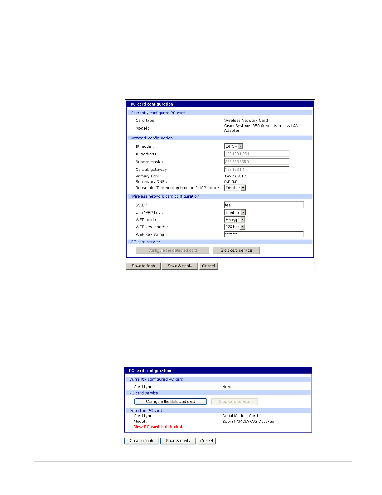
Adding a Serial Modem
SSID - Set Service Identifier and is the name of the wireless LAN n etwork
Use WEP key - Enable or disable the WEP key
WEP mode - Encrypted or unencrypted
WEP key length - The options are 40 or 128 bits if the WEP key is enabled
WEP key string - Refer to the wireless network administrator for the
wireless encryption key string
6. Click Save to flash.
Adding a Serial Modem
The modem must first be inserted and installed on your system before it can
be used. To configure the modem do the following:
1. Access the web interface.
2. From the menu click Configuration under the PC card heading.
Note: The card is automatically discovered and a configuration menu is displayed.
30 Chapter 3
Page 31

Installing and Configuring PC Ca rds
3. Click Configure the detected card.
4. Edit any appropriate parameters and Click Save & apply.
Chapter 3 31
Page 32

Adding a Serial Modem
32 Chapter 3
Page 33

System and Port Logging
Chapter 5
Introduction
The Digi CM provides four options for saving system and port logs. The
options are: a syslog serve r, NFS server , comp act-fl ash card, a nd the Di gi CM
memory. When memory is selected as the stor age locatio n, log files are saved
to volatile memor y, meaning f ile s ar e l o st w he n th e power is turned off. To use
a syslog server, an NFS server, or a compact-flash card, you must first enable
the devices and enter the required information. Compact-flash cards must be
installed before they can be enabled and configured for logging purposes.
System logs track events such as logins, authentication failures, system
configuration changes, and more. Port logs on the other hand document the
data flow through the serial ports. Locations for viewing the system and port
logs is outlined in this chapter.
Enabling Log Storage Location
Enable NFS Server
Log data can also be saved to an NFS server, but the NFS server must be
configured with read and write privileges. To use an NFS server, you must
specify the NFS server’s IP address and its mounting path. Encrypted NFS is
using a SSH connection to tunnel all data. To enable the NFS server for port or
system logging, do the following:
1. Access the web interface.
System and Port Logging
2. Under the Network heading, Click NFS server configuration.
NFS service - Enabled or disabled.
Primary NFS server name
Mounting path on primary NFS server - directory to primary NFS server
Primary NFS timeout - Interval in seconds before timeout (5-3600)
Primary NFS mount retrying interval - Interval in second between attempts to
-IP address of NFS server or DNS name
connect (5-3600)
Enable/Disable encrypted primary NFS server - IF server supports encrypted
NFS server
Encrypted primary NFS server user - User name of server
Encrypted primary NFS server password - password
Secondary NFS service - Enabled or Disabled
Secondary NFS server name - Name of server
Mounting path on secondary NFS server - Directory to server
Secondary NFS timeout (sec, 5-3600) - Timeout in seconds
Secondary NFS mount retrying interval (sec, 5-3600) - Retry interval in seconds
Chapter 5 33
Page 34

Enabling Log Storage Loc ation
Enable/Disable encrypted secondary NFS server - If secondary server supports
encrypted NFS server
Encrypted secondary NFS server user - User name
Encrypted secondary NFS server password - Password
Confirm secondary NFS server password - Repeat password
3. Choose Enabled.
4. Enter the IP address of the primary and secondary (if applicable) NFS
server and the mounting path of each.
5. Click Save & apply.
Enable SYSLOG Server
To enable the Digi CM for system or port logging on a syslog server, do the
following:
1. Access the web interface.
2. Under the Network heading, click SYSLOG server configuration.
3. Choose Enable.
34 Chapter 5
Page 35

System and Port Logging
4. Enter the IP address of the primary and secondary (if applicable) syslog
server and select the syslog facility from the drop down menu.
5. Click Save & apply.
Enable A Compact-flash Card
The compact-flash card must be installed and configured on the Digi CM
before it can be used for system logging or storing Digi CM configuration
information. When storing log files to an external flash card, the size of the
available storag e is de pendent on both the siz e of the card a nd the p ort cou nts
of the Digi CM used. The maximum settings for log file sizes are listed in the
following table. See also Adding a Compact-flash Card on page 27.
Total Flash
Card Size
32
64
128
Digi CM System Log
8 4.6 3.1M
16 4.6 1.53M
32 4.6 762K
48 4.6 500K
8 9.2 6.2M
16 9.2 3.1M
32 9.2 1.53M
48 9.2 1.02M
8 18.4 12.3M
16 18.4 6.2M
32 18.4 3.1M
48 18.4 2.0M
8 36.8 24.6M
(per port)
Port Log
Total Memory
Used
29M
58M
118M
Chapter 5 35
256
16 36.8 12.3M
236M
32 36.8 6.2M
48 36.8 4.1M
Page 36

Configuring System Logging
Enable Digi CM Memory
The Digi CM memory i s al r ea dy e nabled for port lo gg in g and only needs to be
configured for system or port logging. When storing log files to the Digi CM
local memory, a total of 3.5M is available. The amount of memory per serial
port is dependent on the port count of the Digi CM used. The log file sizes are
shown in the following t a bl e are ma xim u m setti n gs. See also Confi gur ing
System Logging on page 36.
Configuring System Logging
To configure the Digi CM for system logging, do the following:
1. Access the web interface.
2. Under System status & log, click System logging.
3. Choose Enabled for System logging and the log buffer size.
4. From the System log storage location, choose the location you want from
the drop down menu. The choices available are dependent on what you
have enabled and/or installed. The Digi CM memory choice is always
available.
System logging - Enable or Disable
System log storage location - Memory or NFS server
System log to SYSLOG server - Enable to store system logs to a SYSLOG
server
System log buffer size (KB, 300 max) - Log buffer size in KB
Send system log by Email - Enable or Disable
Number of log messages to send a mail (1-100) - Number of messages
Digi CM System Log
8
16 200K
300K
32 100K
48 66K
Port Log
(per port)
400K
To tal Memory Used
3.5M
36 Chapter 5
Page 37

System and Port Logging
System log recipient’s mail address
- Email address for log recipient
5. Choose to enable or disable email alerts and the number of log messages
to send. The default value is 5 seconds for the delay in log email
messages.
6. Enter the c ontact email address.
7. Click Save & apply.
Viewing System Logs
The system logs can be viewed from the web interface on the System logging
page or from the location where they have been saved. The following table
lists the file locations of the system logs.
System Logfile
Log Storage File Location
Digi memory /tmp/logs
Compact-flash card /mnt/flash/logs
Syslog server must be viewed on the syslog server
NFS server /mnt/nfs/logs
Chapter 5 37
Page 38

Configure Port L ogging
Configure Port Logging
If a serial port is configured for console server mode, the port logging feature
can be enabled. Port logging allows you to save serial data to the memory of
the Digi CM, a compact-flash card, a syslog server, or to an NFS server. If the
memory is used for port logging, all data will be cleared when the system’s
power is turned off.
You can also define alarm keywords for each ser ial port and send email alerts
or SNMP traps to enable unattended serial data monito ring. The following
steps configure a serial port for port logging in console server mode.
1. Access the web interface.
2. Under the Serial port heading, Click Configuration.
3. Choose All or the Individual port and then Port logging.
4. Configure the settings:
Logging direction - Specify what to log. Options are: Server – only server
output, User – onl y user o utput, Bot h with/ without a rrows – se rver an d user
output with/without directional arrows. Default: server output.
Security advice: When logging user output passwords will be saved into
the log file!
Port log to SYSLOG server - Enable to store port logs to a SYSLOG se rver
Port logging filename - Options are to specify your own or use the port title
for the port log filename
Show last 10 lines of a log upon connect -Show previous last 10 lines of log
when connecting to this port
Strip the ^M from SYSLOG -For logging to a SYSLOG server, strip out all ^M
Monitoring interval -The frequency in seconds to update the port log
38 Chapter 5
Page 39

5. Click Save & apply.
System and Port Logging
Note: When port logging is enabled, a Port Event Handling page is available to create
alarm keywords and send alerts. See Chapter 5 Alerts and Notifications on page
51 for more information.
Chapter 5 39
Page 40

Configure Port L ogging
Viewing Port Logs
The port logs can be viewed from the web interface on the Port logging page
or from the location where they have been saved. The following table lists the
file locations of the system logs.
To view the port logs on the NFS server for port number 5, enter the following
command:
more /mnt/nfs/port5data
Partial logfiles can also be viewed on the web interface by going to Serial port
> Configuration > select a port you want to view >
Port Logfile
Log Storage File Location
Digi memory /tmp/port#data
Compact-flash card /mnt/flash/port#data
Syslog server must be viewed from the syslog server
NFS server /mnt/nfs/port#data
Port logging.
40 Chapter 5
Page 41

Configuring Ports
Chapter 4
Introduction
This chapter provides information on configuring seri al ports. Key port
configuration attributes include whether or not the port is enabled or disabled,
the host mode, which def ines a type of com municati on between the port and a
remote host, the protocol, aut hentication, user access restrictions, and serial
communication attributes.
Enabling and Disabling the Ports
All serial ports may be enabled or disabled individually or as a group from the
web interface.
1. Click Serial port > Configuration > Port number or all
2. Select Enable or Disable from the drop down menu.
3. Click Save to flash and continue with ot her configurations or click Save & apply.
Configuring Ports
Chapter 4 41
Page 42

Resetting Ports
Resetting Ports
Port Title
The Digi CM allows you to restart all processes associated with a port and to
disconnect all sessions.
To reset an in dividual port :
1. Click Serial port > Configuration > Port number.
2. Click Reset this port: Reset.
Reset individual port settings
Individual ports can be reverted to factory defaults.
1. Click Serial port > Configuration > Port number.
2. Click Set this port as factory default: Set.
The Digi CM offers multiple ways to configure the port title; both manually and
automatically. The default is set to “Port Title # xx” with xx being the portnumber.
Automatic Device Recognition allows the Digi CM to evaluate the attached
devices and populate the port title. Additionally the Digi CM can generate a
SNMP trap or send an e-mail in case the response of the device changes or it
stops responding.
If Active detect is selected, a configurable probe string (carriage return =0x0d
by default) is sent to the console port and the response is saved to a file at
/var/run/systemrep_raw.portxx with xx being the port number.
This file is parsed using a script /tmp/cnf/active_detect and the operating
system and device name are written to files: /var/run/HostnamePortxx and
/var/run/OSPortxx.
The commands to parse the system response are use r customizable, so if yo u
have a device that is not r ecognized immedi ately by the Digi CM , he can add a
rule to the file.
If P assive detect is selected, no pr obe string is sent to the attached device but
the port buffer is analyzed.
The script /tmp/cnf/passive_detect is executed and the results are saved to
files: /var/run/Hostnam ePortxx and /var/run/OSPortxx.
After editing the scr ipts as either act ive_detect or p assive_detect, save the m to
flash using the saveconf command so they are not lost after a reboot.
Configuring Automatic Device Recognition
Configure a serial port for Automatic Device Recognition.
1. Access the web interface.
2. Under the Serial Port heading, Click Configuration.
3. Choose All or an Individual port > Serial port parameters.
4. Edit the fields as they apply to your configuration.
42 Chapter 4
Page 43

Configuring Ports
Automatic detection
Use detected port title - Enable if you want the Digi CM to automatically use the
- Enable or disable automatic detection of devices
results of the detection mechanism to populate the port title. Disable if you
want the default port title. If you choose Disable, you can still use the alarm
feature.
Port title - Manual ly entered or automatically popula ted title of the port.
The Digi CM allows access to a port by using only the num be r of the por t titl e,
making it unnecessary to know the serial port number.
The default is set to “Port Title xx” with xx being the port number.
Probe string - The probe string is an ASCII string that is sent to the device.
Special characters are coded in hexadecimal values like:
CR \x0d
LF \x0a
ESC \x1B
Examples are:
Parse string output
root\x0d\x0a root<CR><LF>
\x1Btest\x0d <ESC>test<CR>
\x1B test\x0d <ESC><Space>test<CR>
\x1b\x20test\x0D <ESC><Space>test<CR>
\x1B\x20\x74\x65\x73\x74\x0d <ESC><Space>test<CR>
Detected OS - Di splays the result of the Active or Passive detection process.
Device detection method - If Active is selected a probe string is periodically sent
to the device and the response is analyzed. If Passive is selected, the port
Chapter 4 43
Page 44
Apply all Ports Settings
logging is parsed to determine the device name and the OS.
Detection initiation - Active only if automatic detection is Enabled. Periodically or
If new device is detected are the choices in the drop down menu. If
Periodically is selected, the probe string is sent once every n minutes to the
device while no connection is active to the serial port. When If new device is
detected is selected, the probe string is only sent if a change on the DSR
signal on the serial port is detected. Normally a device will activate the DSR
signal if the serial port becomes active.
Detection delay - The delay before the first active detect process is started and
between active detections.
5. Click Save & apply.
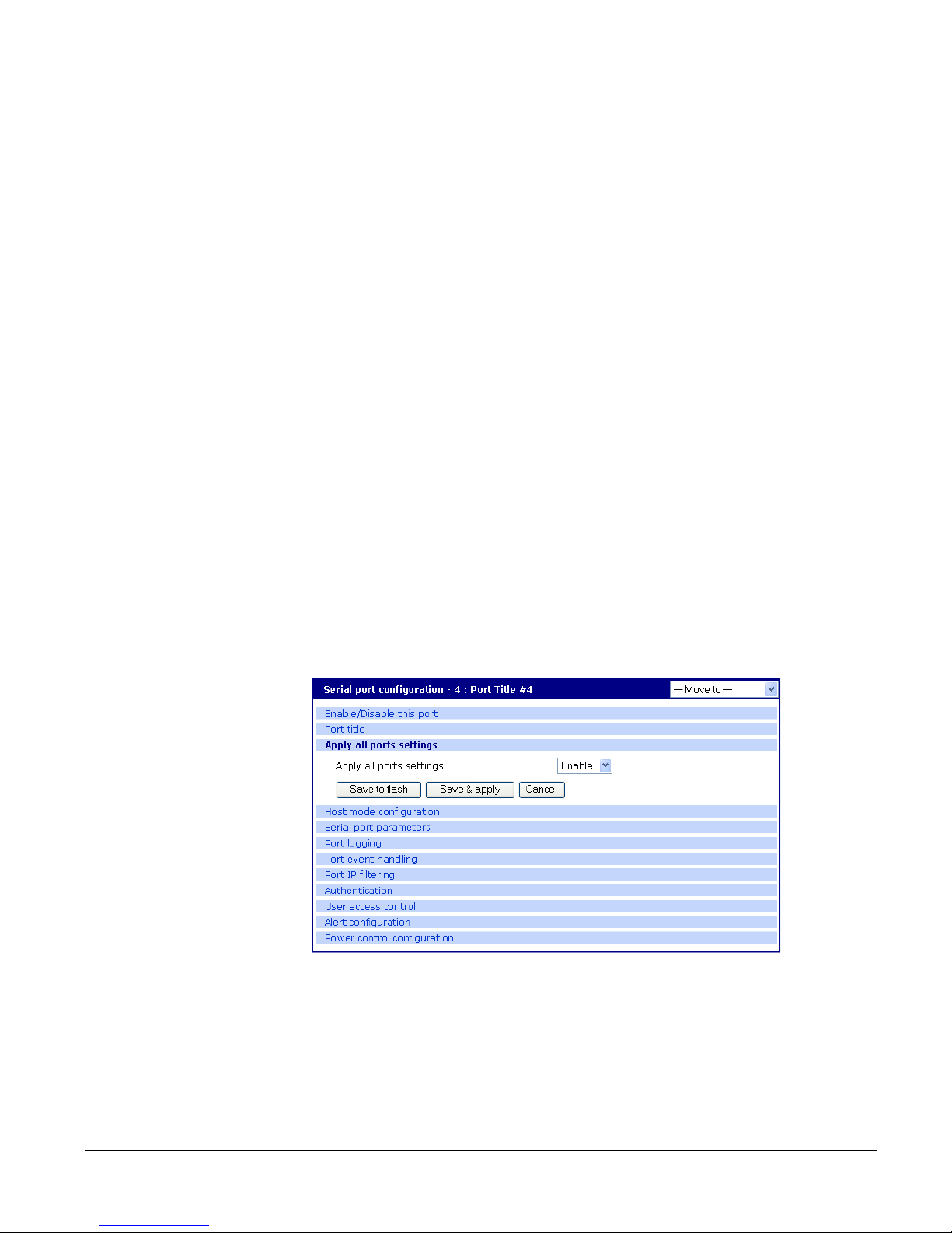
Apply all Ports Settings
The Digi CM supports man aging all p orts simult aneou sly. If changes are made
to the page “all ports”, they are automatically applied to all ports. You can
choose to exclude ports from this feature.
To enable/disable this feature for a port:
1. Access the web interface.
2. Under the Serial Port heading, click Configuration.
3. Choose an individual port >
Host mode configuration.
4. Select Enable or Disable from the drop down menu.
5. Click Save to flash and continue with ot her configurations or click Save & apply.
Note: When changing a parameter for all ports, all settings of the complete page are
applied to all ports.
Host Mode Configuration
The Digi CM provides four modes of communication between serial devices
and remote hosts. Console server, terminal server, dial-in modem, and dial-in
terminal server. These are described in the following sections.
Console Server Mode
Configuring a serial port as a console server creates a TCP socket on the Digi
44 Chapter 4
Page 45

Configuring Ports
CM that listens for a Telnet or S SH client connecti on. When you conne ct to the
TCP socket, you have access to the device attached to the se rial port as
though the device were connected directly to the network. RawTCP is also
supported with the Console Server Mode.
Connection request
serial
Terminal Server Mode
In terminal server mode, t he Digi CM serial port is configured to wait for dat a from
the device connected to the port. If data is detecte d, the Digi CM start s a TCP
session as a Telnet or SSH client to a pre-def ined server. The server must be
defined by you before the port can be configured for a Telnet or SSH client. This
mode is used when you want to ac cess servers on the network from a serial
terminal. RawTCP is also supported with the Terminal Server Mode.
terminals
serial
Connection request
Chapter 4 45
Page 46

Host Mode Configuration
Dial-In Modem Mode
In this mode, th e Digi CM assumes an e xternal mo dem is at tached to the seri al
port and is waiting f or a dial-in connection from a remote site. When a user
dials-in using a terminal application, the Digi CM accepts the connection and
displays the appropriate pr ompt or menu for you th at logged in. Exam ple: User
’root’ would see the command line interface (CLI), whereas the user ’admin’
would see the config menu or CLI depending on the shell for that user.
Dial-In Terminal Server
Dial-in terminal server mode is a combination of the terminal server mode and
the dial-in modem mode. In the dial-in terminal server mode, the Digi CM
assumes the serial por t is connected to an external mod em and is wai ting for a
dial-in connection from a remote site. When you d i al-in using termin al
applications, th e Digi CM accept s the connec tion as a Telnet or SSH client to a
pre-defined server. This mode is most frequent ly used when you want to use
modems to access servers on a network.
46 Chapter 4
Page 47

Configuring Host Mode
To configure a serial port for host mo de, enter the values in the applicable
fields. To access the Host mode configuration screen, do the following:
1. Access the web interface.
2. Under the Serial Port heading, click Configuration.
3. Choose All or an Individual port > Host mode configuration.
Configuring Ports
4. Fill in the highlighted fields as they apply to your configuration.
Host mode - The options are console server mode, terminal server mode,
dial-in modem mode, and dial-in terminal server mode.
Type of console server - The options are MS SAC console -English or
Japanese which you use to provide a graphic user interface to th e
Windows Server 200 3 S pecial A dministration Con sole (see "Mic rosoft SAC
Support" on page 75) and Other, which you use in all other cases.
Rackable Systems Mgmt Card - Enable to use Rackable’s Management card.
Enable/Disable assigned IP - Determines whether an IP address will be
Chapter 4 47
Page 48

Supported Protocols
5. Click Save & apply.
assigned to the port. The default is Enable.
Assigned IP - Also known as alternate IP, thi s fi eld assi g ns an IP ad dr ess to
the port, enabling you to Telnet directly to the serial port using an IP
address (without having to specify a TCP port).
Listening TCP port - This is the TCP port you will specify when connecting
directly to the port using Telnet or SSH.
Terminal server option - The Terminal server option allows you to define the
functionality of this port if a terminal is connected. The Remote connection
establishe s a Telnet/SS H conne c ti on to the destination IP. The Shell
program launches an application on the Digi CM (specified in Terminal
Shell program path.)
Terminal server shell program path - Path to specified shell pr ogram. Used in
Terminal Server mode.
Destination IP - Used in terminal server mode, this is the IP address of the
system that you will be automatically connected to when you access the
port.
Destination port - Used in terminal server mode, this is the TCP port that will
be used when the port you accessed is automati ca l ly conn ect ed to a
system on the network.
Protocol - The options are SSH, RawTCP, and Telnet.
Port escape sequence - The letter to initiate port escape.
Port break sequence - The sequence of characters that sends a break
character to a device.
Inactivity timeout - The timeout length ranges from 1 to 3600 seconds. 0
means that there is no timeout.
Modem init string - Use the default string or enter your own string.
Enable/Disable dial-in modem callback - Enable to use the c allback option.
Dial-in modem callback phone number - Specify the callback number to use.
Enable/Disable dial-in modem test - Enable pe riodic modem test. See
"Configuring For Dial-In Modem Access" on page 85 for details.
Dial-in modem test phone number - Specify test number to use.
Dial-in modem test interval - Specify in hours the interval to test the modem.
Use comment - Determines whether a port user is prompted to add a
comment each time the port is accessed.
Quick connect via - Determines method for connecting to a port when in
console server mode. Available with Telnet/SSH.
Web applet encoding - Supported languages for Java terminal.
Supported Protocols
. In configuring a serial port, you have three protocol options. The three
The Digi CM
supports three
protocol options:
SSH, Raw TCP, and
Telnet.
48 Chapter 4
protocols available are: RawTCP, SSH, and Telnet. Choose SSH as the
protocol when loggin g in from an SSH clie nt program to a ccess a port. Choose
RawTCP when connecting directly to a TCP socket. Choose Telnet when
logging in from a Telnet client program and accessing the ports. Use the Host
Page 49
mode configuration page in the web interface to select the correct protocol.
Serial Port Parameters
In attaching a serial device to a Digi CM serial port, the port parameters must
match. The serial ports by default are enabled, meaning you have full access
to the port. To configure the port parameters for the Digi CM, do the following:
1. Access the web interface.
2. Under the Serial Port heading, Click Configuration.
3. Choose All or an Individual port > Serial port parameters.
4. Fill in the serial port parameters. The following are the defaults: bps=9600,
data bits=8, parity=none, stop bits=1, flow control=none, and DTR
behavior=High when open.
Configuring Ports
5. Click Save & apply
DTR Behavior
DTR can be set on the seri al port to o ne of th ree se ttings: al ways hi gh, alw ays
low, or High when open. Setting the DTR to High when open keeps the DTR
high if a TCP conne ction i s es ta blis hed. The D TR sett ing cann ot be set by you
when the host mode is configured for dial-in modem or dial-in terminal server
mode.
Inter-character Timeout
This setting is on ly available when the host mode protocol is set for RawTCP.
The parameter sets the t ime value fo r the Dig i CM to tran sfer dat a stored in the
buffer. The Digi CM transfers data when the buffer is full using the TCP/IP
protocol. However, if it is not full, the Digi CM will also transfer data dependent
on the timeout value selected.
Chapter 4 49
Page 50

Serial Port Parameters
50 Chapter 4
Page 51

Alerts and Notifications
Chapter 5
Introduction
Alerts and Notifications
The Digi CM can be configured for system alerts and notifications. It sends
email messages when the number of system log messages reaches a certain
value or when an ala r m message is detected in the serial port data. The Digi
CM uses SMTP (Simple Mail Transfer Protocol) for sending the notifications.
To use SMTP, the system administrator must configure a valid SMTP server
for sending the emails. The Digi CM suppor ts three types of SMTP servers:
SMTP server without authentication, SMTP server with authentication, and
POP before SM TP.
The Digi CM also suppo rts SNMP (Simple Network Management Pro to c ol) , a
protocol used to mana ge a network a nd monitor d evices on a netw ork. System
and port alerts can also be sent using SNMP traps. The Digi CM supports both
versions 1 and 2 of the SNMP protocol. The main function of SNMP on the
Digi CM is to allow a system administrator to query remote devices for
information.
PANIC
serial
PANIC
Chapter 5 51
Page 52

Configuring SMTP Alerts
Configuring SMTP Alerts
Most SMTP servers check the sender’s email address with the host domain
name to verify the address as authentic. Consequently, when assigning an
email address for the device email address, any arbitrary username with the
registered hostname may be used. An example is username@company.com.
To configure the Digi C M for S MTP ale rt s, the foll owing pa rame ters are r equ ired:
SMTP server - Use either the hostname or the IP address.
Device mail address - Specify the sender’s email address for the log and
alarm delivery.
SMTP mode - Specify the type of SMTP server to use.
Username and password - These fields are required for POP before SMTP
and SMTP with authentication servers.
To configure SMTP alerts on the Digi CM, do the following:
1. Access the web interface.
2. Under the Network heading, choose SMTP configuration.
3. Fill in the required fields. SMTP with authentication and POP before SMTP
require usernames and passwords.
4. Click Save & apply.
SNMP Information
Applications such as NMS (Network Management System) or an SNMP
The Digi CM
supports SNMP
authentication,
power on, an d
link up traps.
browser can exchange information with the Digi CM and control actions to the
unit. The protocol functions defined for SNMP includes GET, SET, GET-Next,
GET -Bu lk, and TRAP. Below are the defini tions of the pro tocol f unctio ns foun d
in SNMP. Authentication, power on, and link up traps are supported.
.
Protocol Function
GET Queries a device for more information
SET Makes changes to a device’s state
GET-Next After an initial GET query, goes to the next value
GET-Bulk Retrieves tables of information and security functions
TRAP Notifies a system administrator of a significant event
52 Chapter 5
Page 53

Traps
Alerts and Notifications
There are additional traps that can be set at the port level. The followi ng t ab le
shows where the trap is under Serial port > Configuration on the web
interface, trap name, configure options, and the trap functions. The MIBs for
login traps can be found at http://ftp.digi.com/support/utilities/digicm/
Trap Location Trap Name Function
Notify about any login
Port access menu Port login trap
Alert configuration Port login trap
Alert configuration
Alert configuration
Alert configuration
Port event handling
Device
connection trap
Active detection
trap
Dial-in modem
test trap
Keyword
notification trap
action to the port
access menu
(succeed and fail)
Notify about login to
this specific port
(succeed and fail)
(only available if host
mode is set to
"Console serv er ")
Notify about a change
of the DTR signal line
(only available if host
mode is set to
"Console serv er ")
Notify about changes
in the device’s
response to the probe
string (see also
"Automatic Device
Recogniti on" on p age
19, only available if
host mode is set to
"Console serv er ")
Notify about modem
test (succeed and fail)
(only available if host
mode is set to "Dial-in
modem")
Notify about the
occurrence of a
keyword in the port
log
(only available if host
mode is set to
"Console serv er ")
Chapter 5 53
Page 54

Configuring SNMP
Configuring SNMP
To configure the Digi CM for SNMP do the following:
1. Access the Digi CM web interface.
2. Under the Network heading, choose SNMP configuration.
3. Fill in information for the MIB-II system objects section and choose Yes
under EnableAuthenTrap. The fields are de scribed in the following section:
sysContact - Identity of the contact person managing the MIB-II system.
sysName - The name identifying the system. By convention, this is the fully
qualified domain name of the Digi CM unit. An exa mple is:
DigiCM@companyname.com.
sysLocation. - The physical location of the unit such as Room 264 or
Engineering Lab.
sysService (Read only). - A series of values, separated by commas,
indicating the set of services the system provides. By default the Digi CM
only supports Application (7) service leve l.
EnablePowerOnTrap. - Determines whether the SNMP agent generates a
trap each time the Digi CM is started.
EnableAuthenTrap. - Indicates whether t he SNMP age nt process is p ermitted
to generate authentication failure traps.
EnableLinkUpTrap. - Determines whether the SNMP agent generates a trap
each time the network connection comes up.
EnableLoginTrap - Determines whethe r the SNMP agent genera tes a trap for
each login.
Note: Trap values override all other configuration information, meaning all other
authentication failure traps can be disabled with this setting.
4. Enter Access control settings ba sed on the following field descripti o ns:
IP Address - Defines what application s can access the Digi CM SN MP agent
to exchange information and control actions. If no IP addresses are listed,
any application can access the SNMP agent.
Community - The options are public or private.
Permissions - The options are Read only or Read/Write.
54 Chapter 5
Page 55

Alerts and Notifications
5. Enter Trap receiver settings based on the following f ield descriptio ns:
IP Address - Enter the IP address of the device receiving the trap aler ts.
Community - The options are public or private.
Version - Choose the SNMP version, either version 1 or version 2c.
6. Click Save & apply.
Managing the SNMP Protocol
The Digi CM SNMP protocol can be managed using an NMS or SNMP
browser. However, before the NMS or SNMP browser can access the data,
the Access control settings must list the IP addr e ss of the ho st fr om wh ich the
browser is executed. See the preceding graphic for details.
Chapter 5 55
Page 56

Configuring Port Event Handling
Configuring Port Event Handling
Once an SMTP or SNMP server has been config ur ed , it can be used to send
port-related aler ts and noti fications. The follow ing describes ho w to configure a
port for port event handling.
1. Access the web interface.
2. Choose Serial port > Configuration.
3. Choose a port to configure and then Port logging.
4. Select Enable.
5. Choose Save & apply.
6. Choose Port event handling.
The following page appears.
56 Chapter 5
Page 57

Alerts and Notifications
7. Select an action and enter the keyword for the port event handling.
8. Enable Email notification.
Note: It is assumed that SMTP is configured firs t. If not, see "Conf igu ri ng SM TP Ale rts"
on page 52.
9. Enter the title of the Email (subject line).
10.Enter the Email recipient’s address.
11. Enable SNMP trap notification.
12.Enter the title of the trap.
13.Choose either to use the global SNMP settings by enabling "Use global
SNMP configuration" or specify spe c ia l settings for thi s por t.
14.Enter the IP address of the trap receiver.
15.Enter the SNMP community
16.Select the version.
17.Complete configuration and then choose Save & apply.
Note: Key word is any text string that will trigger an alert when it traverses the serial port.
Chapter 5 57
Page 58

Config Alerts for Automatic Device Recognition ( ADR)
Config Alerts for Automatic Device Recognition (ADR)
Before configuring the alerts for Automatic Device Recognition, be sure you
have configured the port for ADR as described in "Configuring Automatic
Device Recognition" on page 42.
1. Access the web interface.
2. Under the Serial Port heading, Click Configuration.
3. Choose All or an Individual port > Alert Configuration.
4. Follow the Email A lert step s to config ure the ema il alert or follow the SM TP
Notification to configure SMTP.
Email Alert SMTP Notification
Enable "Email Alert for active
detection"
Enter the Title of email
Enter Name and email address
where the email should be sent.
Enable "Active detection trap"
Configure the trap receiver by one of the
following two ways:
Enter "Use global SNMP configuration"
OR
Enter the IP address of the trap receiver,
the SNMP trap community and select the
version
5. Complete configuration and choose Save & apply.
58 Chapter 5
Page 59

User Administration
Chapter 6
Administering Users
Required Privileges
Only root and admin can administer users. The root user has unlimited
administration privileges. Admin can view and change all attributes except
those that belong to the root user.
Procedure
1. Access the web interface.
2. Under System administration, choose Users administration.
The following screen appears.
User Administration
Note: The username on the Digi CM is case sensitive.
3. Do one of the following:
To... Do the Following...
A. Click Add.
Add a user
Edit a user
Remove a user
B. Fill in the attribute fields. See the table that follows for
information on attribute fields.
C. Click Add.
A. Click on the username.
B. Fill in the attribute fields. See the table that follows for
information on attribute fields.
C. Click Submit.
A. Check the box that corresponds to the user you want to
remove.
B. Click Remove.
C. Choose OK at the prompt.
Chapter 6 59
Page 60

Administering Users
4. Click Apply changes.
Field Description
User name
User Fields
Name for the user, which must be between 3 and 29
characters and cannot include colons (:), less than or greater
than signs (< >), ampersand (&), spaces, or quotation marks.
The at sign @ and period . are acceptable.
The username on the Digi CM is case sensitive.
Group to which the user is assigned. Groups include Root,
Select group
Password
Confirm password Confirms the password.
Shell program
SSH public key
authentication
SSH public key to
use
Select new SSH
public key version
Select new SSH
public key file
System Admin, Port Admin and User. See "User Groups" on
page 11 for more information
Password to assign to the user. This must conform to the
rules stipulated above for a user name.
Interface presented to the user when he/she logs on to the
system from a Telnet or SSH connection.
Alternative method of identifying yourself to a login server.
More secure than just a password.
Current public file key or create a new public file key
SSH1 only supports one type of key
SSH2 supports both RSA and DSA key types
Location for the SSH public key file
60 Chapter 6
Page 61

Configuring Security and Authentication
f
Chapter 7
Configuring Security and Authentication
Introduction
The Digi CM provides several ways to control access to the network and the
devices on the network. One method is through IP filtering, which allows or
prevents users with specific IP addresses from accessing devices or serial
ports on the network. IP filtering can be permitted or restricted for all ports
globally or on a per port basis. Another access control method involves
restricting or permitting specific users. Users can be easily added or removed
from either a restricted or permitted users list. Sniff session access, which
allows multiple users to access a single port, is also discussed.
The Digi CM provides for various authentication metho ds. They are: Local,
RADIUS, TACACS+, LDAP, and Kerberos. Authenti cation m ay be confi gure d
where a secondary method is attempted if the primary method fails.
Configuring Network IP Filtering
The Digi CM offers built-in firewall functionality to limit TCP/IP traffic to and
from certain networks, TCP ports and interfaces. The func tionality
implemented is based on the Linux tool IPtables.
Filter IP: 192.168.1.0
Filter Mask: 255.255.255.0
192.168.1.108
192.168.5.10
serial
192.168.5.10
192.168.1.108
Chapter 7 61
Page 62

Configuring Network IP Filtering
It is also possible to enable or disable specific services of the Digi CM:
Telnet console (TCP/IP port 23)
SSH console (TCP/IP port 22)
Web configuration (TCP/IP port 80)
Interface - The interface is the name of the networ k interface vi a which a pa cket
is received. It can be one of these three values:
eth0 : the default Ethernet in terface of the Digi CM
eth1 : th e secondar y int erface ad ded by u sin g a PC car d or wir eless card
all : both in terfaces
Option - The Option determines that this rule will be applied to the IP address/
Mask specified or to its inverse -meaning the rule will be applied to all except
those specified.
Normal : applied to the hosts included
Invert : applied to the hosts excluded
IP address/Mask - The IP address/Mask specifies the host range by entering
base host IP address followed by “ /” an d sub ne t m ask. Th e ho st ran ge ca n b e
one of the following scenarios by changing the value:
• Only one host of a specific IP address
• Hosts on a specific subnet
•Any host
Specified host range Input format
Any host 0.0.0.0/0.0.0.0
192.168.1.120 192.168.1.120/255.255.255.255
192.168.1.1 ~ 192.168.1.25 4 192.168.1.0/255.255.255 .0
192.168.0.1 ~ 192.168.255. 254 192.168.0.0/255.255.0.0
192.168.1.1 ~ 192.168.1.12 6 192.168.1.0/255.255.255 .128
192.168.1.129 ~ 192.168.1.254 192.168.1.128/255.255.255.128
Port - A TCP/IP Port on the Digi CM that other hosts try to access. The p ort can
be specified using a single value or a range of ports in the form of: port1:port2,
where port1 defines the lowest port and port2 the highest port.
62 Chapter 7
Page 63

Configuring Security and Authentication
Chain rule
- The Chain rule determines whether access from the hosts is
allowed or not. It can be one of these two values:
ACCEPT : access allowed
DROP : access not allowed
A user can add a new IP filter ing rule by en tering the values for th e para meters
and clicking the Add button on the right hand side of the table. A user c an
remove a rule by using the Remove button. After having finished editing the
table be sure to save the settings to flash using the Save to flash button or to
save and apply them using the Save & apply button. Be aware that the change s
need to be applied before becoming active.
This screen shot shows 5 IP rules that have been established.
Rule #1 defines SSH access to the Digi CM (port 22). The Normal option
specifies that the rule applies to all addresses listed. The rule says to Accept
traffic from these addresses for Port 22.
Rule #2 defines Telnet access to the Digi CM (port23). The Invert option
specifies that the rule applies to all addresses except those listed. The rule
says to Drop traffic from all addresses not listed.
Rule #s 3, 4,and 5 define access to the Digi CM using HTTP (port 80).
However, rule 3 blocks all traffic, rule 4 allows access from IP address
192.168.1.0. and rule 5 allows access from IP address 192.168.2.0.
Chapter 7 63
Page 64

Configuring User Access Control
Configuring User Access Control
Another method to co ntrol a ccess to the serial ports on the Digi CM is through
the User Access Control configuration. This configuration can be done on a
per port basis or globa lly by selectin g the All Port s option. It i s not necessar y to
have users added to the system to assign rights. Howe ver, for the permissions
or restrictions to be enforced, the username must match exactly or the
application will not recognize any misspellings and is also case-sensitive. If
you want to add users, click on "System administration > Users
administration". For more details how to add users refer to "Administering
Users" on page 59.
Note: Users do not need to be authenticated locally; they can be users on any
configured authentication server.
MIKE
JOE
An administrator can choose either one of two strategies to assign rights to a port:
• allowing “everyone” access to a port and then restricting access to certain
users or
• speci fying every user that has right to a port.
If <<everyone>> is checked, all users configured locally or that are using a
remote authentication mechanism like LDAP or Kerberos have access to this
port. If <<ever yone>> is not chec ked, everyone allowed to access t his port
needs to be listed.
When entering usernames for access permission or restrictions, t he username
must be entered exactly as the username found on the remote authentication
server or configured locally. The username is case sensitive.
In the following example, there are three users configured on a Digi CM: Jeff,
Tim and Paul .
If you want to give Tim and Paul read/write access and power access to this
port, you could either
64 Chapter 7
Page 65

• grant rights to Paul and Tim,
Configuring Security and Authentication
Note: The usernames and passwords on the Digi CM are case sensitive.
• or restrict rights to Jeff
Note: The usernames and passwords on the Digi CM are case sensitive.
Chapter 7 65
Page 66

Configuring User Access Control
(
)
Sniff Sessio n
A sniff session enables multiple user s to access a single serial port for viewing
the data stream. Anyone that is registered for a sniff session can access a
specific serial port even if someone else is using the port. The Digi CM
supports multiple concurrent sniff sessions.
serial
(Read only access)
Port 3
Network (Ethernet)
log in
port 3
Main Session
Read/write access
log in
port 3
Sniff Session
There are four options for a Sniff Session mode, disabled, input, output, and
both. You can configur e the sniff session modes on a per-port basis from the
Serial port configuration page.
Enable/Disable sniff mode
• Disabled -The sniff mode is disabled and no one can enter a sniff
session after the first person is logged on.
• Enabled - - Allows everyone with access the following options while in
sniff mode:
Sniff session display mode
• server output - View all data to a serial port from a remote connection
• user input - View all data from a seri al port to a remote connection
• both - See all data transmitted or received through a serial port
Display data direction arrows
• Enable/Disable - displays arrows to indicate direction of data to or from
the server. When accessing the port as a second user the global "Port
escape menu" will be displayed. See "P ort Escape Menu" on page 16.
66 Chapter 7
Page 67

Configuring Security and Authentication
r
Authentication
Permit monitor only mode
• Enable: A user with “Monitor" permissions can only connect to the port
in read only mode any time.
• Disable: A user with “Monitor" permissions can connect if a read/write
user has a connection to the port. A read only session is automatically
disconnected if the main user (read/write sessio n) disconne cts from th e
port.
The Digi CM supports multiple methods of user authentication. The following
methods are supp orted: Loca l, TACACS+, RADIUS, LDAP, and Kerberos. The
type of authentication protocol you use is dependent on your environm ent.
4. Access granted
Serve
1.
Connection request
PC
Authentication
server
Configuring Authentication Methods for Port Access
You can choose between having a single authentication method, such as
RADIUS, or an authentication method where a Local authentication service is
used in addition to the RADIUS, LDAP, TACACS+ server, or Kerberos. These
options are listed when you configure the Digi CM for au thentication. To
configure a Digi CM for authentication, do the following:
1. Access the web interface.
2. Under the Serial port heading, choose Configuration.
3. Choose All or an Individual port >
Authentication.
4. From the drop down menu, choose an authentication method. A
configuration screen fo r that particular authentication method is displayed.
The following figure displays the parameters for setting up a RADIUS
2. Query
User ID
3. Accept
User ID
Chapter 7 67
Page 68

Configuring Aut hentication for the Web Server
server as the primary authentication server and Local authentication if the
primary authentication method fails.
Note: Remote authentication to Port access menu can be obtained from Serial port >
Configuration > Port access Menu
5. Fill in the appropriate fields.
6. Choose Save & apply changes.
Configuring Authentication for the Web Server
1. Access the web interface.
2. Choose Network > Web server co nfiguration.
The following screen appears.
3. Choose an authentication method and then Save & apply.
When using remote authentication for the web server, such as Radius,
TACACS+, LDAP or Kerberos, you must also be added to the local
database. The user password must be different from local authentication
or it will do local authentication instead of remote. See "Administering
Users" on page 59 for details.
Once your password is approved by the authentication server, the Digi CM
uses the local permission rights to provide proper access privileges for you
to ports and the configuration.
68 Chapter 7
Page 69

Custom and Default Menus
Chapter 8
Introduction
The Digi CM has several default menus for easy configuration and access by
different users. De pending on access privileges, the menus available are the
Web Interface, Configuration Menu, and Port Access Menu. A Custom Menu
feature for creating menus is also available through the web interface.
The Custom Menu feature enables system administrators to create menus for
specific users; in other words, system administrators can create a customized
interface to selected p orts. Custom menus can only be configured via the web
however, they can only be accessed via the shell (command line).
Making Custom Menus
Before making custom menus, plan the kind of menus and menu items you
want available to your users. A good plan would include the following:
1. Add users to the system.
2. Create a menu name with sort and display features.
3. Add menu items and submenus to the new menu.
4. Assign users to the menus.
Custom and Default Menus
Adding Users
You cannot assign users to a menu until you have added users to the system.
To add users, do the following:
1. Access the web interface.
2. System administration > Users administration > Add
Chapter 8 69
Page 70

Making Custom Menus
3. Enter the User name and User group from the drop down menu.Select
Custom menu from the drop down menu for the Shell program.
4. Click Add to add the user.
5. Continue to add users as needed.
Note: You do not need to Save to flash or Apply changes to add users.
Creating Menu Names
To make a custom menu, do the following:
1. Access the web interface.
2. Custom Menu > Configuration.
3. Enter the Menu Name to assign and click the Add Menu button.
The menu is added.
4. Click the hyperlink to the menu you just created.
5. From the drop down menu, select th e way to Sort and Display items.
6. Click Save & apply.
7. Repeat as required to create additional menus.
70 Chapter 8
Page 71

Custom and Default Menus
Adding Menu Items
Once you have defined a menu name and adde d user s, you can then add
menu items. To add menu items, do the following:
1. Custom Menu > Configuration > Menu Name hyperlink for the menu you
want to configure.
2. Choose Menu Items > Add Item.
The following screen appears.
3. Fill in the desired parameters. The parameters are:
Key - Assign any letter or number except a value already used by another
menu item.
Label - Assign a label or name for the menu item.
Create new submenu - Assign a name for a new submenu that this menu item
will be assigned or linked to.
Go to existing submenu - Choose an existing submenu from the drop down
menu that this menu item will be assigned or linked to.
Connect to serial port - Connects you to a specified port.
Connect to clustered serial port - Connects you to a clustered port.
Telnet to a remote host - Enter a remote host’s IP address or hostname.
SSH (Secure Shell) to a remote host - Enter the hostname or IP address of a
remote host and the remote username.
Execute a custom command - Enter a customized command that is any valid
command on the command line with acceptable user privileges.
Chapter 8 71
Page 72

Default Menu
4. Choose Apply.
5. Repeat this p r ocedure to add more menu items.
Note: To add or configure submenus, select the Submenus hyperlink on the Menu
Configuration page.
Assigning Users to a Menu
Once a menu has been created, users can be assigned to the menu by doing
the following:
1. Access the web interface.
Default Menu
2. Configuration > Custom Menu >
Menu Users.
A list of available users is displayed.
3. Choose a menu for a user by selecting a menu from the drop down
Assigned Menu list.
4. Choose Save & apply.
Port Access Menu
The PortAccess menu is a flat (one level) menu showing all ports, port titles
and the mode of each port.
Using the PortAccess menu you have a complete ove rview of al l port s and can
initiate a connection to any of them.
When you choose to co nnect to a specif ic port, you are pr ompted again for the
username and password.
72 Chapter 8
Page 73

Custom and Default Menus
There are multiple ways to access the PortAccess menu:
• Assi gned IP address (see "Configuring Host Mode" on page 47)
• TCP/IP port 7000
• TCP/IP port 22 or 23 if the “Shell program” is set to “port access menu” for
this specific user (see chapter "Administering Users" on page 59)
• By calling “portaccessmenu” from the command line
The PortAccess menu allows simple access to each port.
By typing the number of the port to connect to, the Digi CM initiates a
connection to this port using the appropriate protocol (Telnet of SSH).
You can also change your own password by using the “P” Key.
If the Digi CM is configured to be the master in a master-slave scenario, the
“S” key will bring up a list of all slaves. Sele cting a slave will then spawn a
connection to the Port Access Menu of the slave.
When using a Digi CM 48 not all ports can be displayed on one screen. Ports
33-48 can be viewed after hitting the <Enter> key.
Chapter 8 73
Page 74

Default Menu
74 Chapter 8
Page 75

Microsoft SAC Support
Chapter 9
Microsoft SAC Support
About Digi CM Support for Microsoft Windows Server 2003
The Digi CM provides a brow ser-based user int erface to Microsof t’s text-b ased
Special Administration Console (SAC), an integral part of Windows Server
2003 Emergency Management Services (EMS). Both the English and
Japanese version s of SAC are now supported. When a server running
Windows Server 2003 is connected to a Digi CM serial port, key SAC
functions--normally accessed from the command line--are available fro m a
graphical user interface (GUI). SAC features accessible from this interface
include:
• Reset and shutdown
• Show perfor mance values like memory utilization
• Show and configure IP settings per interface
• Show the process list and kill processes
Note: While the EMS port is available at all times using T elnet or SSH, the special GUI is
available only while SAC is active.
Chapter 9 75
Page 76

Set Up Overview
Set Up Overview
Set up for Digi CM SAC support is a three-step process:
1. Set up the Windows Server 2003 for SAC support. To do this, ensure that
the COM port used for console traffic is properly set up. This includes
designating a COM port for console communication and setting the port
speed (baud) appropriately. For further information please refer to Setting
Up the Windows Server 2003 Port below.
2. Cable the console port on the Windows Server 2003 to a Digi CM port. See
the cabling information in Chapter 17.
3. Set up the Digi CM for SAC support. See "Setting Up the Digi CM for SAC
Support" on page 76.
Setting Up the Windows Server 2003 Port
1. Sign on to the Windows Server 2003 as the administrator.
2. Access the command line.
3. Use the bootcfg command to redirect console traffic to the correct COM
port. The following is the command synta x and an example. See the
Microsoft documentation for additional information on the SAC feature.
Command Syntax
bootcfg /ems on /port com# /id # /baud 115200
where com# is the COM port to which co nsole traf fic will be redirecte d, # is the
is the number of the boot entry, and the port speed is set to the
Digi - recommended rate (although you can use any rate supported by
Windows Server 2003).
Command Example
In this example, console output is redirected to COM 2, the boot entry is
specified as 1, and the port speed set to 115200.
bootcfg /ems on /port com2 /id 1 /baud 115200
Setting Up the Digi CM for SAC Support
To set up a serial port to provide access to the Windows Server 2003 console
port, do the following:
1. Access the web interface.
2. Choose Serial port > Configuration.
3. Choose a port.
4. Choose Host mode configuration.
The Host mode configuration page appears.
5. Set the Host mo de to Con sole serv er and the Type of console server to MS
SAC -English (or Japan ese) console as sho wn in the following figure.
76 Chapter 9
Page 77
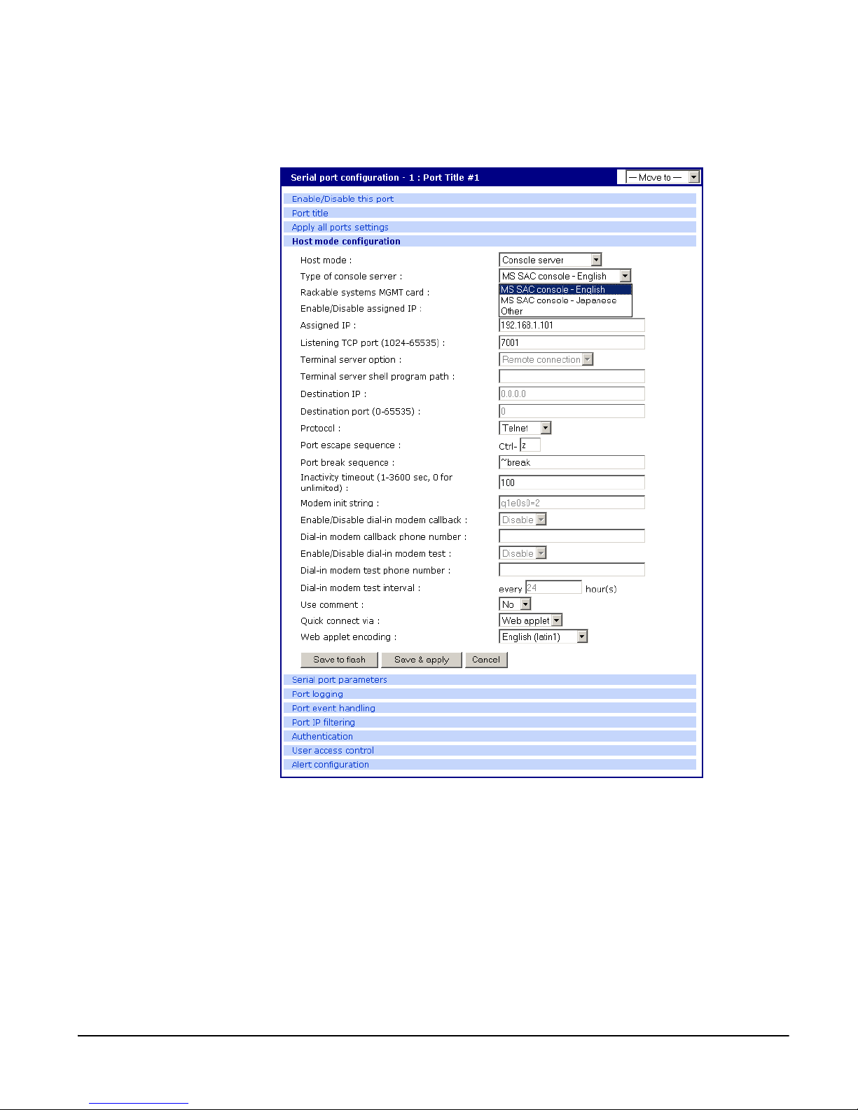
Microsoft SAC Support
6. Set other f i elds as appropriate.
7. Click Save & apply.
8. Configure serial port commun i cation settings , by doing the follo wing:
a. Choose Serial port parameters from the menu.
b. Adjust settings as required. Th is includes ensuring that the Baud rat e
matches the setting on the Windows Server 2003 serial port and Flow
control is set to None. Ignore the DTR behavior field.
c. Click Save & apply.
Chapter 9 77
Page 78
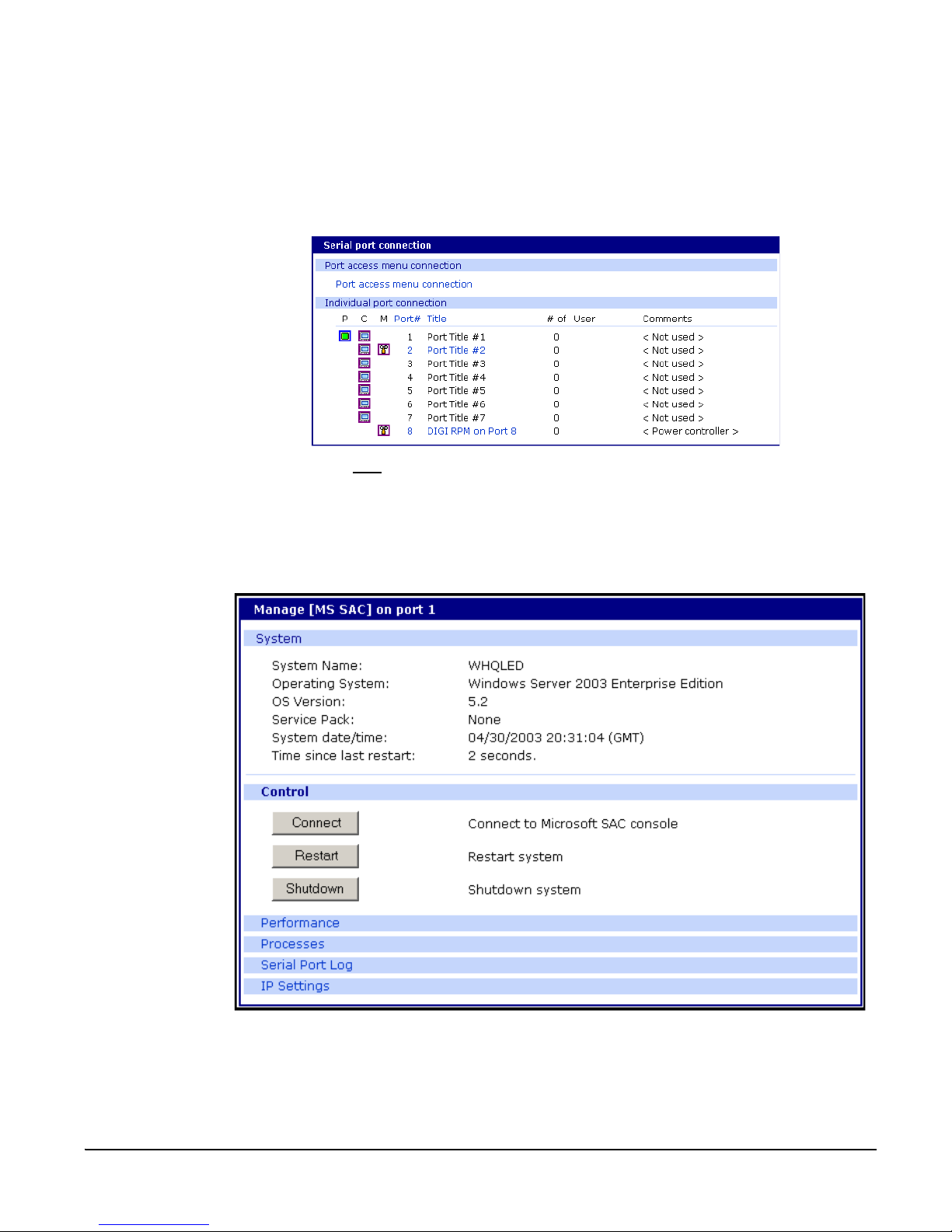
Accessing the Windows Server 2003 Console Port from the Digi CM GUI
Accessing the Windows Server 2003 Console Port from the Digi CM GUI
To access the Windows Server 2003 console port, do the following:
1. Access the web interface.
2. Choose Serial port > Connection.
A screen similar to the following appears.
3. Click on the title
of the port to whic h the W indows Server 2003 console port
is connected.
Note: If support for "Windows Server 2003" and "Rackable Systems Management Card"
is selected a menu will appear and you must choose between the two functions.
A screen similar to the following appears.
4. Use the Digi CM GUI to perform SAC functions. The following table
describes attributes of the controls on the GUI.
78 Chapter 9
Page 79

Microsoft SAC Support
Field Description
Connect Connects to the SAC console port via the command line interface.
Restart Reboots the Microsoft Server 2003.
Shuts down the Microsoft Server 2003.
Shutdown
Performance Provides access to Microsoft Server 2003 status information.
Caution! This switches off the server and you can no longer access it
remotely.
Process
Serial Port
Log
IP Settings Provides access to IP settings, enabling you to verify and change settings.
Provides access to the process list, which allows you to view and kill
active processes.
Provides access to port logging infor mation.
Chapter 9 79
Page 80

Accessing the Windows Server 2003 Console Port from the Digi CM GUI
80 Chapter 9
Page 81

Rackable Systems Management Card
Chapter 10
Introduction
Set up
Rackable Systems Management Card
Rackable Systems manufactures a management card that is built into some of
their servers. It interfaces between the Digi CM and the server’s serial port. In
normal mode, it allows transparent communication between the Digi CM and
the server. After detecting an escape sequence, it allows you to control
functions from the server inde pendently of the mai n processor. The contollable
functions are lis ted below:
• Switching power on or off
• Rebooting
• Turning the status LED on or off
• Programming the LCD panel
• Reading the temperature from inside the server
• Setting the power on delay
The Digi CM offers a graphical web based user interface to manage the
Rackable Systems Management Card.
Set up of the Digi CM to support the Rackable Systems Management Card
To set up the serial port to provide access to the Rackable Systems
Management console, do the follo wing:
1. Access the D igi CM’s web interface.
2. Under the Serial Port heading choose Configuration.
3. Choose a port.
4. Choose Host mode configuration.
The Host mode configuration page appears.
5. Set the Host mode to Console server.
6. Set the “Rackable Systems Mgmt Card” support to Enable.
7. Click Save & apply.
Configure serial port communication settings:
1. Choose Serial port parameters from the menu.
2. Adjust the settings as required. The defaults for the Rackable Systems
Management Card are identical to these of the Digi CM:
Baud rate 9600
Data bits 8
Parity None
St op bi ts 1
Flow control None
DTR behavior High when open
Chapter 10 81
Page 82

Set up
3. Click Save & apply.
Assign a port name:
1. Choose port title from the menu.
2. Enter a port title.
3. Click Save & apply.
Accessing the Rackable Systems Management Card from the Digi CM user interface
1. Access the D igi CM’s web interface.
2. Under the Serial Port heading choose Connection.
A screen similar to the following appears.
3. Click on the icon in the M (Manage) column or on the title of the port to
which the Rackable Server is conn ected.
A screen similar to the following appears.
4. Use the Digi CM user interface to perform Rackable Sys tems Management
Card functions. The follo wing desc ribes attribut es of the user interfac e controls.
82 Chapter 10
Page 83

Rackable Systems Management Card
.
Field Description
Control
The first column shows the current state.
Power status
Reboot
Connect
LED Mgmt
LED
Management
LCD Mgmt
Currently
displayed
message
Erase
Save Save currently displayed message to flash memory.
Show saved
LCD message
upon startup
Contrast
Phantom
Properties
Temperature
Power delay
Power sense
Communication
settings
Baud Rate
Three buttons are available to initiate an action to either, power
on, power off or restart the server. Dependant on the current status Power on or Power off is disabled.
Reboot the Rackable Server by sending a 500ms reset signal to
the server.
Spawn the Java Telnet applet or the local T elnet/SSH application
to connect directly to the port.
To control the LED in the front of the Rackable Server.
The first columns shows the current status of the LED. Three but-
tons are available to select the activity of the status LED: turn on,
turn off and blinking. Either of these buttons is disabled.
Shows the message that is currently displayed on the LCD display.
This function clears the LCD display.
The saved message stays saved to flash.
The first columns shows the current status: Yes or No.
This parameter defines which message is displayed upon startup
of the server, either the saved message or the standard: “Rackable Systems Phantom Vx.xx”.
Set a contrast for the LCD panel.
The default is 50, the range is 0 – 100.
Indicates current temperature inside the Rackable Sy stems Serv er.
Time in seconds before the server starts up after applying power
(0-98 seconds, 99 means no power on delay).
The power sense option toggles between sensing server power
on the reset header or on the J7 connector. Most applications will
use the “Rese t” o pti on. This o pt ion s hou ld be set be fo re shi ppi ng
from Rackable Systems, but may need to be reset if somehow
changed after shipping.
Configure the baud rate used to communicate with the Rackable
Systems Management Card. For this change to become effective
reset or power-cycle the Management card, and be sure to
switch the port settings in the Digi CM port settings.
Chapter 10 83
Page 84

Set up
84 Chapter 10
Page 85

Configuring Remote Dial-In Access
Chapter 11
Introduction
Configuring Remote Dial-In Access
The Digi CM supports dial-in connections from remote sites for out-of-band
access. In this configuration, the Digi CM has serial ports configured for
external modems and waits for dial-in connections from remote sites. If you
dial-in using a t erminal application, the Digi CM accepts the connection and
displays a menu of available serials ports. In a dial-in termina l server mode,
the Digi CM makes a TCP connection with either a Telnet or SSH client to a
pre-defined server. RawTCP is also an option for dial-in users.
For more information on the different types of Host mode configuration, see
"Host Mode Configuration" on page 44.
Configuring For Dial-In Modem Access
To configure a seria l por t for a dia l-in mode m, ent er the valu es for the se fie lds:
Host mode, Modem init str ing, and Inact ivity timeout. To access the Host mode
configuration screen, do the following:
1. Access the web interface.
2. Under the Serial port heading, choose Configuration.
3. Choose a specific port under Individual port configuration and then choose
Host mode configuration.
4. Select Dial-in modem for the H ost mode in the drop down menu.
5. Fill in the appropriate fields as they apply to your configuration.
Chapter 11 85
Page 86

Configuring For Dial-In Mo dem Access
Modem init string - The default modem i nit st ring i s q1e0 s0=2. The i nit st ring
sets the modem to quiet mode, echo off, and Auto Answer on two rings.
The modem init string is use d for initial izing an externa l modem att ached to
a Digi CM serial port. See your modem user manual for more inform ation.
Callback - For security reasons, the callback feature can be activated.
If callback is enabled, the Digi CM does not accept any incoming calls.
After the incoming call is rejected, a callback is initiated to the phone number configured i n the “Dial-in modem callback phone number”.
Modem test - To ensure the proper functionality of the modem, the Digi CM
has the ability to test the modem connection in a configurable interval.
The modem test allows you to specify a phone number and an interval.
86 Chapter 1 1
Page 87

Configuring Remote Dial-In Access
After the system has booted, the interval has elapsed, and the modem is
not in use, the specified dial number is called. The modem trains and
receives a login prompt from the other side (normally another Digi CM).
If the login-in prompt (login: ) is detected the line is disconn ected aga in and
the modem test is considered successful.
Two ports can call each other using this modem test procedure.
Please be aware that the tests will fail if the ot her modem is in use.
There are multiple ways to review the information about the mode test:
• syslog in the Digi CM itself:
07-16-2004 12:45:01 > Port #16 - Modem Test started. Calling to 1234444567.
07-16-2004 12:45:22 > Modem connected through Port #15
07-16-2004 12:45:22 > Port #16 - Modem Test succeeded
In this example a modem connecte d to port 16 is calling another
modem connected to port 15.
Any errors occurring are captured in the syslog file as well.
• e-mail based notification
The Alert configuration dialog of the port configuration, contains multiple
settings:
The title of the e-mail and the address can be configured.
To be able to configure e-mail n oti fica ti on s, a p r im a ry SM TP ser ver has
to be configured under Network > SMTP configuration.
• SNMP configuration
It is also possible to receive notifications using SNMP traps.
When using SNMP traps the glob al settin gs for IP add ress, Comm unity
Chapter 11 87
Page 88

Adding a PC Modem
6. Click Save & apply.
Adding a PC Modem
A PC card slot is provid ed on the front panel of th e Digi CM. The graphic below
has an arrow indicating the PC card slot.
To install and configure the PC modem on the Digi CM, do the following.
and Version can be used, or specified separately.
The Trap MIB can be downloaded from support.digi.com (select your
product and go to Diagnostics, Utilities and MIBs).
PC card slot
Digi CM 32 shown
1. Insert the card into the PC slot.
2. Access the web interface.
3. From the menu, choose Configuration under the PC card heading.
4. Choose Discover a new card.
The Digi CM searches for a PC card and displays a configuration menu.
5. Enter the appropriate parameters in the configuration menu.
6. Click Save & apply.
Configuring For Dial-In Ter minal Server Acce ss
The host mode Dial-In Terminal Server is identical to the host mode Terminal
Server but allows you to configure a modem init string. In this mode an
incoming modem connection is automatically connected to an IP address.
To configure a serial port for a dial-in terminal server access, enter the values
for these fields: Host mode, Destination IP, Base Port, Protocol, Inactivity
timeout, and Modem init string. To access the Host mode configuration
screen, do the following:
1. Access the web interface.
2. Under the Serial port heading, choose Configuration.
3. Choose a specific port under Individual port configuration and then choose
Host mode configuration.
88 Chapter 1 1
Page 89

Configuring Remote Dial-In Access
4. Select Dial-in term i nal ser ver for the Host mo de from the dr op do wn men u.
5. Fill in the appropriate fields as they apply to your configuration.
Destination IP - The IP address of the system that you will be automatically
connected to when you access the port.
Destination port -´ The TCP port that will be used when the port you
accessed is automatically connected to a system on the network.
Protocol - The protocol that will be used to establish the connection to
Destination IP: port. The options are SSH, RawTCP, and Telnet.
Inactivity timeout - The timeout length ranges from 1 to 3600 seconds; 0 is
unlimited timeout.
Modem init string - Use the default string or enter your own string.
6. Click Save & apply.
Chapter 11 89
Page 90

Configuring For Dial-In Terminal Server Access
90 Chapter 1 1
Page 91

Power Controller
Chapter 12
Introduction
Power Controller
The Power Controller feature allows the administrators of the Digi CM to use
console management to control power functions. Power control consists of
three basic functions: on, off, and reboot (power cycle). There are two typical
scenarios when using a power con troller. The simplest scenario is a non- serial
device connected to a powe r contro lle r (fo r examp le, a n envir onmental sensor
controller or a tape backup device). The power controller is configured and
accessed through the Digi CM.
This illustration shows the a power contro ller configured through the Digi CM
for non-serial devices.
The second scenario is a serial device (such as a router or server) managed
through a port on the Digi CM with it s power supply mapped through the po wer
control feature. After configuration is complete, you need only reference the
console management port on the Digi CM to also manage power. The Power
Controller featur e handles t he relati onship of a specific outlet to a seria l device
as if the power supply was also connected to the same port as the serial
device. In other words, you don’t need to see the physical connection or
remember which outlet controls a specific serial device after configuration - the
Digi CM does that for you.
Chapter 12 91
Page 92

Installing Power Controller
The following illustration shows a Sun server configured through a serial port
connection on the Digi CM 32.
Installing Power Controller
To connect the Digi RPM power contr oller to the Digi CM use the straight-thru
cable provided wi th t he Dig i RP M uni t. Pl ug one side into the “C onso le” port o f
the Digi RPM and the o ther i nto an y port of the Di gi CM. If you p lan to conn ect
multiple power controllers, set up all of them as described before proceeding.
For details on how to configure the Digi RPM for cascading refer to "Cascading
Multiple Digi RPM Units" on page 100.
If you are using any other manufacturer of power controllers, please refer to
"About Serial Port Cabling" on page 143 for more information.
Before proceed ing, plu g the power con trolle r into an approp riate po wer sou rce
and turn it on.
Note: The DIP switches on the Digi RPM are used for cascading. Make sure that the dip
switches of the first unit are set to off. For more information about cascading refer
to "Cascading Multiple Digi RPM Units" on page 100.
Configuring Power Controller
Only system administrators can add a p ower cont rolle r althoug h aut horized
users may reconfigure outlets or serial ports.
Configure the serial port parameters to match the power controller
1. Log in to the Digi CM (username root, password dbps).
2. Click Serial port > Configuration.
3. Select the port number of the serial port you want to connect to the power
controller.
4. Select the Serial port parameters:
Baud rate 9600
Data bits 8
Parity None
St op bi ts 1
Flow control None
DTR behavior High when open
5. Click Save & apply.
6. Continue by adding the power controller.
92 Chapter 12
Page 93

Power Controller
Add the power controller
1. Log in to the Digi CM (username root, password dbps).
2. Click Power Controller > Configuration.
3. Select the port number of the serial port you want have connected to the
power controller(s), the manufacturer of the power controller, and the
number of units to be cascaded (1 means that one unit will be connected
(no cascading)).
Note: The number of cascaded units cannot be changed later, so make sure you have
all power controllers connected before proceeding.
The default title is the manufacturer brand and the port number it is
connected to. You have the ability to change this title in step 5 if needed.
4. Click Add controller.
5. After the control ler is detected a utomatically, you can correct the number of
ports if necessary or edit the port title.
6. Click Save & apply.
7. Continue by setting the alarms and tresholds.
Chapter 12 93
Page 94

Setting Alarms and Thresholds
Setting Alarms and Thresholds
Power Controller allows administrators to set an alert via E-mail notification or
an SNMP trap when environmental conditions exceed specifications.
1. Under Power Controller click Alarms & thresholds.
2. Enter the appropriate parameters. Select the condition(s) for an alert and
enter the information for the alert (E-mail or SNMP trap or select both).
Note: If multiple power management units are cascaded, the alarm threshold is set for
Note: To set up an E-mail alert it is assumed that the mail server has already been set
the sum of a ll outlets.
up. If not, go to "Configuring SMTP Alerts" on page 52. If the SMTP server is not
set up, the E-mail option will not be available.
3. Click Save & apply
4. Continue by configuring the outlets.
94 Chapter 12
Page 95

Outlet Configuration
The following proce dure allow s you to se tup the p ower supplie d to your device
from the power controller.
1. From Power controller, click Outlets.
2. Click the outlet number to configure.
Power Controller
3. Select the seria l po rt nu mb er t hat con trols the devic e co nnecte d to t he D igi
CM (if any). If the port number has a title, it will appear.
Note: If you want to add a title or change the existing title, go to Serial port >
Configuration and select the port number that you want to add or change the title.
Enter the title and click
> Title > Outlets and select the outlet you are configuring to continue.
Save & apply . Go back to Power Controller > Configuration
4. If you are not selecting a serial port number, you can modify a user’s
access on this screen. Enter the User Access Control parameters - see
"User Access for Power Controller" on page 96.
5. Click Save to flash and repeat steps 2- 4 for each outlet you want to
configure.
6. Click Save & apply.
Chapter 12 95
Page 96

User Access for Power Controller
Note: The screen above shows that serial port one on the Digi CM is connected to a Sun
Server that is supplied power from outlets 1 and 2 on the power controller. In the
example above, Gilligan has access to the power outlets.
7. To select the parameters for the User Access Control, click the User Access
link. You may grant specific users permission to access an outlet or restrict
access for specif ic users from an outl et. For more information see "User
Access for Power Controller" on page 96.
User Access for Power Controller
The Digi CM can be configured to allow all users or specific users access to
the power controller feature as well as restricting specific users to the power
controller feature. User Access is configured on an outlet by outlet basis.
Note: User Access to a serial device that is connected to the power controller in
configured under Serial Port > Configuration > Port # > User Access
Configuring to Allow Specific Users Access
To configure t he Digi CM for specific users, you must deselect
<<Everyone’s>> access and add the specific user and access as in the
following steps.
1. Log in to the Digi CM (username root, password dbps)
2. Click Power Controller > Configuration > Outlets > Select the outlet # to
configure.
3. Select the port to configure to the outlet. If it is a non-serial device select
None.
4. Edit the outlet title. If there is a serial port, the port title will appear and
cannot be edit ed from this screen.
5. Click Save & apply.
96 Chapter 12
Page 97

Power Controller
6. Under Everyone uncheck the Access type and click Save to flash.
7. Enter the user that will have access and check the Access type.
Note: Port is access to the port. Monitor is access to sniff. Power is access to the power
management.
8. Click Save to flash. Repeat steps 7 and 8 for additional users.
9. Click Save & apply after all users have been entered.
Note: The screen above shows outlets 1 & 2 control power to the Sun Server configured
Configuring to Restrict Specific Users
on port 1 of the Digi CM. Outlets 3 and 4 are not serial devices. Gilligan has been
designated the specific user to control outlet # 3.
To restrict specific users, you must select access for << Everyone>> and add
the restricted user by deselecting his or her access.
1. Log in to the Digi CM (username root, password dbps)
2. Click Power Controller > Configuration > Outlets > Select the outlet # to
configure.
3. Select the port to configure to the outlet. If it is a non-serial device select
None.
4. Edit the outlet title. If there is a serial port, the port title will appear and
cannot be edit ed from this screen.
5. Click Save & apply.
6. Check Everyone and click Save to flash.
7. Enter the username that will NOT have access, uncheck the Access types
that are restricted, and click Add.
Chapter 12 97
Page 98

Power Controller Management
Note: Port is access to the port. Monitor is access to sniff. Power is access to the power
management.
8. Click Save to flash and repeat steps 7 and 8 for additional users.
9. When all users have been added Click Save & apply.
Note: Gilligan does not have access to Outlet # 4.
Power Controller Management
The Power Controll er Manage ment option allows you to cha nge outlet sett ings
or get a quick update of the power controller status.
1. Under Power Control click Management.
The Power controller management screen gives a quick view of all the power
controllers and the current status of the connection. The Port # and
Manufacturer fields are a link to the specific power controller statistic page
which displays information for the power co ntroller. If the status is
‘Disconnected’ the links are inactive.
98 Chapter 12
Page 99

Power Controller
2. Click either the Port # or the power controller title.
The Power controller statistics screen appears to show the Alarm threshold,
Current temp, Circuit breaker condition, RMS voltage, RMS current, an d Max
current detected.
The Clear button will reset the Max current detected to 0.0 amps. From this
screen click Outlets.
3. Select the outlet number that you would like to manage.
Note: The screen below shows that all the outlets are powered On and outlet 3 is
Rebooting, therefore the Backup Tape Device is power cycling.
4. Click
Power on, Power off
Chapter 12 99
, or
Reboot
depending on what you want the outlet to do.
Page 100

Cascading Multiple Digi RPM Units
Cascading Multiple Digi RPM Units
The Digi RPM power controllers can be cascaded when used with the Digi
CM.
The DIP switches on the front panel of the Digi RPM allow configuring unique
identities (ID) to the Digi RPMs so they can be identified. In a cascade d
environment each unit has to be configured to a unique ID.
To cascade the Digi RPM connect a serial port of the Digi CM to the Console
Port of the first Digi RPM using a straight-thru cable. Connect the “Cascade”
Port of the first Digi RPM to the “Console” Port of the second.
Following an exa mple of two cascaded Digi RPMs connected t o a Digi CM.
Please note that the ID for the first unit is set to 0 and for the second unit it is
set to 1.
100 Chapter 12
 Loading...