

Page 1

317-7492 Wireless Radio
SMCS: 1900-38
TOOL
OPERATING
MANUAL
NEHS1081
May 2009
R
TOOL
OPERATING
MANUAL
Page 2

Important Safety Information
Think Safety
Most accidents that involve product operation,
maintenance, and repair are caused by failure
to observe basic safety rules or precautions.
An accident can often be avoided by
recognizing potentially hazardous situations
before an accident occurs. A person must be
alert to potential hazards. This person should
also have the necessary training, skills, and
tools to perform these functions properly.
Improper operation, lubrication,
maintenance, or repair of this product can
be dangerous and could result in injury or
death.
Do not operate or perform any lubrication,
maintenance, or repair on this product until
you have read and understood the
operation, lubrication, maintenance, and
repair information.
Safety precautions and warnings are provided
in this manual and on the product. If these
hazard warnings are not heeded, bodily injury
or death could occur to you or to other
persons.
The hazards are identified by the “Safety Alert
Symbol” and followed by a “Signal Word” such
as “DANGER”, “WARNING”, or “CAUTION”.
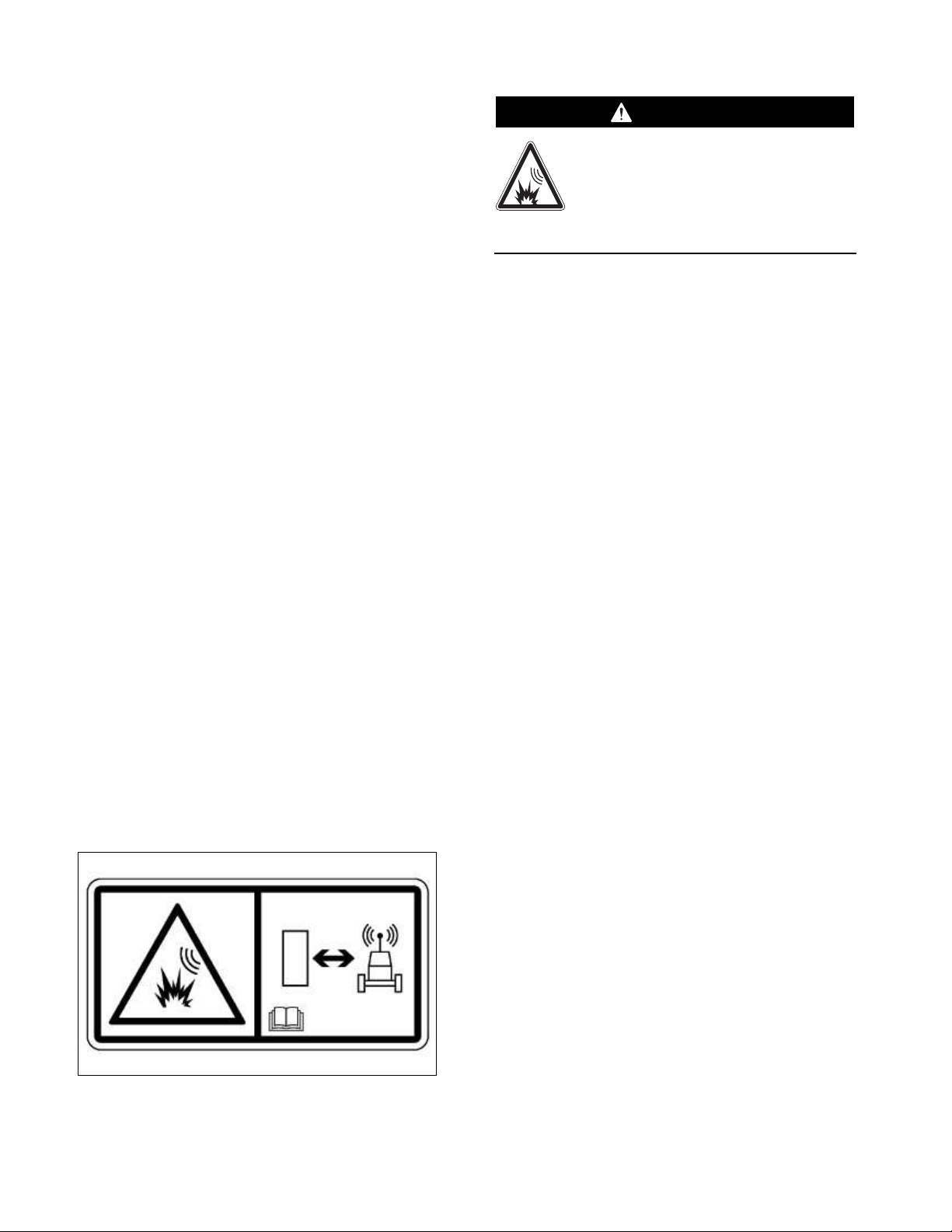
The Safety Alert “WARNING” label is shown
below.
The meaning of this safety alert symbol is as
follows:
Attention! Become Alert! Your Safety is
Involved.
The message that appears under the warning
explains the hazard and can be either written
or pictorially presented.
Operations that may cause product damage
are identified by “NOTICE” labels on the
product and in this publication.
Caterpillar cannot anticipate every possible
circumstance that might involve a potential
hazard. The warnings in this publication
and on the product are, therefore, not
all-inclusive. If a tool, procedure, work
method, or operating technique that is not
specifically recommended by Caterpillar is
used, you must satisfy yourself that it is
safe for you and for others. You should
also ensure that the product will not be
damaged or be made unsafe by the
operation, lubrication, maintenance or
repair procedures that you choose.
The information, specifications, and illustrations
in this publication are on the basis of
information that was available at the time that
the publication was written. The specifications,
torques, pressures, measurements,
adjustments, illustrations, and other items can
change at any time. These changes can affect
the service that is given to the product. Obtain
the complete and most current information
before you start any job.
When replacement parts are required for this
product, Caterpillar recommends using
Caterpillar replacement parts or parts with
equivalent specifications including, but not
limited to, physical dimensions, type,
strength, and material.
Failure to heed this warning can lead to
premature failures, product damage,
personal injury, or death.
2
WARNING
WARNING
Page 3

Contents
Literature Information
Safety Section . . . . . . . . . . . . . . . . . . . . . . . . 3
General Information Section . . . . . . . . . . . . . 3
Operation Section . . . . . . . . . . . . . . . . . . . . . 3
Tooling Configurations Section . . . . . . . . . . . 4
Service Parts Section. . . . . . . . . . . . . . . . . . . 4
Regulatory Information Section . . . . . . . . . . . 4
General Information Section
Introduction . . . . . . . . . . . . . . . . . . . . . . . . . . 4
Safety-Blast Zone Warning . . . . . . . . . . . . . . 4
Minimum PC Requirements . . . . . . . . . . . . . . 4
Additional Contact Information . . . . . . . . . . . 4
Specifications. . . . . . . . . . . . . . . . . . . . . . . . . 5
Nomenclature. . . . . . . . . . . . . . . . . . . . . . . . . 6
Component Storage. . . . . . . . . . . . . . . . . . . . 6
Operation Section
Install/Configure the Wireless (W-CA3)
Radio . . . . . . . . . . . . . . . . . . . . . . . . . . . . . . . 7
Connecting the W-CA3 to the CA3 . . . . . . . 7
Configuring the PC for Communication
With the W-CA3 . . . . . . . . . . . . . . . . . . . . . 8
Creating a Wireless Profile on the PC . . . . 8
Electronic Technician Configuration for
the W-CA3 . . . . . . . . . . . . . . . . . . . . . . . . 16
Activating and Changing the Internal
Settings of the W-CA3 . . . . . . . . . . . . . . . . 19
Connecting the W-CA3 to a PC. . . . . . . . . 19
Installing the USB Drivers for the W-CA3 . 20
Viewing/Changing the Internal Settings
for the W-CA3 . . . . . . . . . . . . . . . . . . . . . 22
Additional Settings Available for
Modification in the W-CA3 . . . . . . . . . . . . 254
Upload Configuration File: . . . . . . . . . . . . 31
Download Configuration File:. . . . . . . . . . 31
Tooling Configurations Section
Tooling Configurations . . . . . . . . . . . . . . . . . 34
W-CA3 to PC . . . . . . . . . . . . . . . . . . . . . . . 34
W-CA3 to CA3 to DataLink . . . . . . . . . . . . 34
Magnetic Mount W-CA3 to CA3 . . . . . . . . 34
Using the Remote Antenna . . . . . . . . . . . . 35
Using the Suction Cup Mount . . . . . . . . . . 35
Service Parts Section
317-7492 Wireless Radio Group . . . . . . . . . 36
317-7512 Suction Cup Mount . . . . . . . . . . . 36
326-9607 Antenna Group . . . . . . . . . . . . . . 37
Related Components . . . . . . . . . . . . . . . . . . 37
317-7484 Communications Adapter 3
(CA3) Group . . . . . . . . . . . . . . . . . . . . . . . 37
Regulatory Information Section
Regulatory Information and Certifications . . 38
Statement To Original Equipment Manufacturer
(OEM) Integrators . . . . . . . . . . . . . . . . . . . . 39
Literature Information
This manual should be stored with the tool
group.
This manual contains safety information,
operation instructions, and maintenance
information.
Some photographs or illustrations in this
publication show details that can be different
from your service tool. Guards and covers
might have been removed for illustrative
purposes.
Continuing improvement and advancement of
product design might have caused changes to
your service tool, which are not included in this
publication.
Whenever a question arises regarding your
service tool or this publication, please consult
Dealer Service Tools (DST) for the latest
available information.
Read and understand the precautions listed
about safety before operating this service tool.
General Information Section
The General Information section describes
tooling functions and features. It provides
useful information on safety, individual parts,
additional tooling, and resources.
Operation Section
The Operation section is a reference for the
new operator and a refresher for the
experienced operator.
Photographs and illustrations guide the
operator through correct procedures for using
the tool group.
Operating techniques outlined in this
publication are basic. Skill and techniques
develop as the operator gains knowledge of
the service tool and its capabilities.
3
Page 4
Literature Information
(continued)
Tooling Configurations Section
The Tooling Configurations section describes
methods of connecting the wireless USB radio
to 317-7484 Communications Adapter 3, the
PC, and optional tooling for various functions.
Service Parts Section
The Service Parts section describes tooling
replacement parts and part number
availability.
Regulatory Information Section
The Regulatory Information section describes
Federal Communications Commission (FCC)
requirements, compliance, and the
manufacturer statement of authorized use.
General Information Section
Introduction
The 317-7493 Wireless Radio is designed to
be used outdoors with the 317-7484
Communications Adapter 3 and related
components for transmitting data from a
machine to a remote PC (dealer supplied) for
data logging and analysis.
Safety-Blast Zone Warning
1. If the machine is equipped with a
317-7493 Wireless Radio, make sure the
proper warning film(s) are clearly visible to
the operator (such as on the dash) during
normal operation of the machine.
230-1340 Film
If the machine is required to work
within 12 m (40 ft) of a blast area,
the operator must disable and
remove the 317-7492 Wireless
Radio. Failure to do so could result in
serious injury or death.
2. If the machine is required to work within
12 m (40 ft) of a blast area, disconnect and
remove the wireless radio from the
machine. This will prevent any signals from
being transmitted during machine
operation.
Minimum PC Requirements
A dealer supplied PC (Laptop Computer) is
required to configure the 317-7493 Wireless
USB Radio.
Minimum PC requirements are:
• IBM® PC compatible with Pentium IV
2.4 GHz processor
• 512 MB RAM minimum
• 1 GB of available hard disk drive
• 40X speed CD-ROM drive or 8X speed
DVD drive or greater
• 14.1” XGA screen (800x600) or greater
• Built-in pointing device or mouse
• Microsoft Internet Explorer 6.0 or greater
Additional Contact Information
For additional product support questions
concerning this tool, contact the Caterpillar
Dealer Service Tools Hotline at:
U.S.A.: 1-800-542-8665
Illinois: 1-800-541-8665
Canada: 1-800-523-8665
World: 1-309-675-6277
Fax: 1-309-494-1355
dealerservicetool_hotline@cat.com
4
WARNING
Page 5

Specifications
317-7493 Wireless Radio
317-7493 Wireless Radio (W-CA3)
Description Specification
Operating Voltage 5 VDC at 700 mA maximum
Operating Temperature -40° to 85°C (-40° to 185°F)
Dimensions 122 x 104 x 40 mm
(4.82 x 4.08 x 1.57 in)
Antenna Connections 2 x RP-TNC
Mounting Magnet Integrated 3.6 kilogauss neodymium
Reliability SAE J1455/1960 standard
WWiirreelleessss LLAANN IInntteerrffaaccee
Standard: IEEE 802.11a/b/g
Frequency: 2.4/5 GHz
Data Rate: Up to 54 Mbps with automatic fallback
Modulation: DBPSK (1 Mbps)
DQPSK (2 Mbps)
CCK (11, 5.5 Mbps)
BPSK (6, 9 Mbps)
QPSK (12, 18 Mbps)
16-QAM (24, 36 Mbps)
64-QAM (48, 54 Mbps)
WWLLAANN SSeeccuurriittyy
WEP (Wired Equivalent Privacy)
WPA/WPA2/802.11i
- 128-bit TKIP/CCMP/(AES) encryption
- Enterprise mode (802.1X)
· LEAP (WEP only), PEAP, TTLS, TLS
· GTC, MD5, OPT, PAP, CHAP,
· MSCHAP, MSCHAPv2, LS-MSCHAPv2
UUSSBB IInntteerrffaaccee
Type: USB 2.0 Device (full/low speed)
Connector: 8-pin circular DIN
RNDIS software support
NOTE: The 317-7493 Wireless Radio is
intended for outdoor use.
326-9606 Wireless Radio Antenna
Description Specification
Frequency Bands
Of Operation 2.4 GHz, 4.9 to 5.8 GHz
Gain 2.2 dBi
326-9607 Magnetic Mount Antenna
Description Specification
Frequency Bands
Of Operation 2.4 GHz, 4.9 to 5.8 GHz
Gain 3 dBi
5
317-7493 Wireless Radio (W-CA3) Frequency Specifications
Band Frequency Channel Location
2.4 GHz 2412, 2417, 2422, 2427, 2432, 2437, 2442, 2447, 1-11 North America, EU
2452, 2457, 2462
2467, 2472 12, 13 EU
4.9 GHz 4920, 4940, 4960, 4980 L184, L188, L192, L196 Japan
11
5260-5320 MHz 5260, 5280, 5300, 5320 52, 56, 60, 64 EU
22
5470-5725 MHz 5500, 5520, 5540, 5560, 5580, 5600, 5620, 5640, 100, 104, 108, 112, 116, 120, EU
22
5660, 5680, 5700 124, 128, 132, 136, 140
5725-5825 MHz 5745, 5765, 5785, 5805, 5825 149, 153, 157, 161, 165 North America
11
Channel Use in Japan Only. 22Dynamic Frequency Selection Only
Page 6
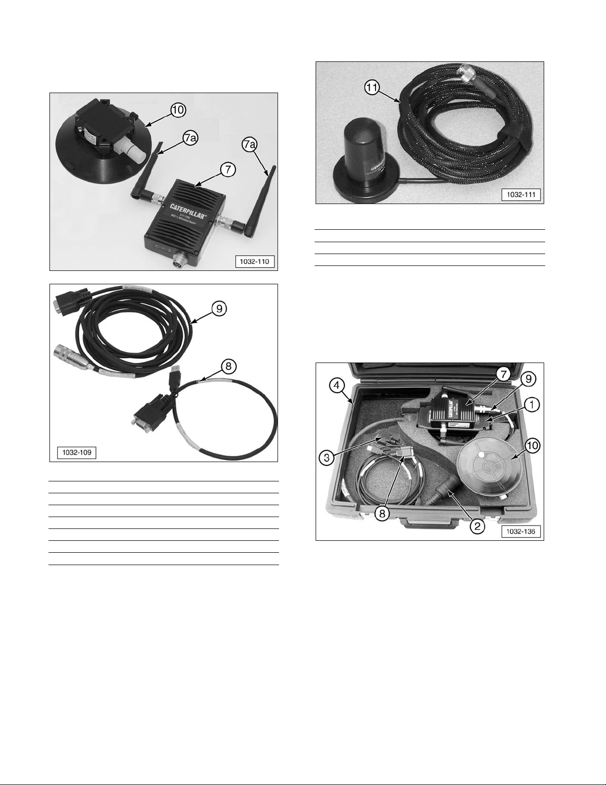
Nomenclature
317-7492 Wireless Radio (W-CA3) Kit
Item Part No. Description Qty
7 317-7493 Wireless Radio Group (W-CA3) 1
7a 326-9606 Antenna 2
8 317-7496 WiFi/USB PC Cable Assembly 1
9 317-7510 WiFi/CA3 Cable Assembly 1
10 317-7512 Suction Cup Mount (optional) 1
NOTE: Throughout this manual the 317-7493
Wireless Radio is also referred to as the
“W-CA3”. In addition, the 317-7485
Communications Adapter 3 can be referred to
as the “CA3”.
326-9607 Antenna Assembly (Optional)
Item Part No. Description Qty
11 326-9607 Antenna Assembly 1
Component Storage
NOTE: The 317-7493 Wireless Radio and
related components can be stored with the
317-7484 Communications Adapter 3 Group,
as shown.
(1) 317-7485 Communications Adapter 3 (CA3).
(2) 317-8981 Cable Assembly.
(3) 317-7487 Cable Assembly.
(4) 6V-7145 Case.
(7) 317-7493 Wireless Radio (W-CA3).
(8) 317-7496 Cable Assembly.
(9) 317-7510 Cable Assembly.
(10) 317-7512 Suction Cup Mount (optional).
6
Page 7
Install/Configure the Wireless
(W-CA3) Radio
IMPORTANT NOTE:
To comply with US and Canadian regulatory
requirements, read, understand, and follow
the guidelines in the Regulatory Information
section in this manual when configuring
and operating the 317-7493 Wireless Radio
(W-CA3) and related components.
The 317-7492 Wireless Radio Kit connects to
the 317-7485 Communications Adapter 3 in
order to create an 802.11 wireless connection
to an Electronic Technician enabled PC.
IMPORTANT NOTE:
When the 317-7492 Wireless Radio Kit is
purchased, it is deactivated by default.
Before operating the wireless radio (W-CA3)
for the first time, it must be configured for the
country it will be used in. Perform the steps
in the “Viewing/Changing the Internal
Settings of the W-CA3” section. Once
complete, return to this section to proceed
with the setup of the CA3 and wireless radio.
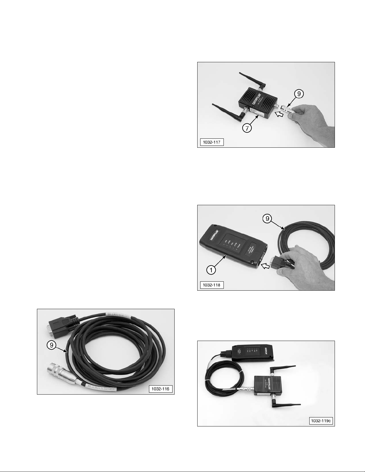
Connecting the W-CA3 to the CA3
1. Connect 317-7493 Wireless Radio (W-CA3)
(7) to the 317-7485 CA3 (1) with provided
317-7510 Cable Assembly (9).
(9) 317-7510 Cable Assembly.
2. Connect 317-7510 Cable Assembly (9)
round DIN connector to 317-7493 Wireless
Radio (W-CA3) (7) plug.
(7) 317-7493 Wireless Radio (W-CA3).
(9) 317-7510 Cable Assembly.
3. Plug 317-7510 Cable Assembly (9) DB style
connector into 317-7485 Communications
Adapter 3 (CA3) (1).
(1) 317-7485 Communications Adapter (CA3).
(9) 317-7510 Cable Assembly.
4. This illustration shows the completed
wireless radio setup.
Completed CA3/W-CA3 configuration.
7
Page 8
Configuring the PC for Communication
With the W-CA3
NOTE: The W-CA3 does not need to be
connected to the PC in order to configure
communication between the W-CA3 and the
PC.
The W-CA3 can be used with any 802.11a or
802.11b/g enabled wireless card. In order to
communicate with the W-CA3, a “Profile” in the
“Wireless Client Utility” must be set up for the
wireless card. The following is one example
for configuring this profile.
NOTE: These steps are shown as an example
and may not appear exactly the same on the
PC being used. There are numerous wireless
card and software manufacturers on the
market and Caterpillar cannot accurately
portray every example here. The important
thing to remember is that
eeaacchh
of these steps
MUST be completed in the “Wireless Client
Utility” for the PC being used in order for Cat
ET to be able to communicate through the
wireless radio (W-CA3).
NOTE: It is advisable to consult with the
IT Department of the dealership to complete
these steps. Many users may not have the
authority to make the changes documented.
The IT Department should also be involved in
evaluating whether the use of the W-CA3 radio
will interfere with the wireless network for the
dealership/business. If the settings for the
W-CA3 radio need to be changed to account
for this interference, proceed to the section
“Changing the Internal Settings of the W-CA3”
of this manual.
Default Settings for the W-CA3:
• SSID: W-CA3
• Wireless Band: 802.11 b or g
• Wireless Mode: Ad-Hoc (Auto IP enabled
check box is found under network
settings)
• Channel Number Search: Channel 11
(eleven)
• Security: WEP (104/128 bit)
• Security Key:
35373c57222750362a334c6a71
Creating a Wireless Profile on the PC
In order for the Cat ET enabled PC to
communicate with the W-CA3 radio, the PC
wireless card must be set up appropriately.
These steps are shown for reference only, and
the instructions listed here may not be the
same for every PC.
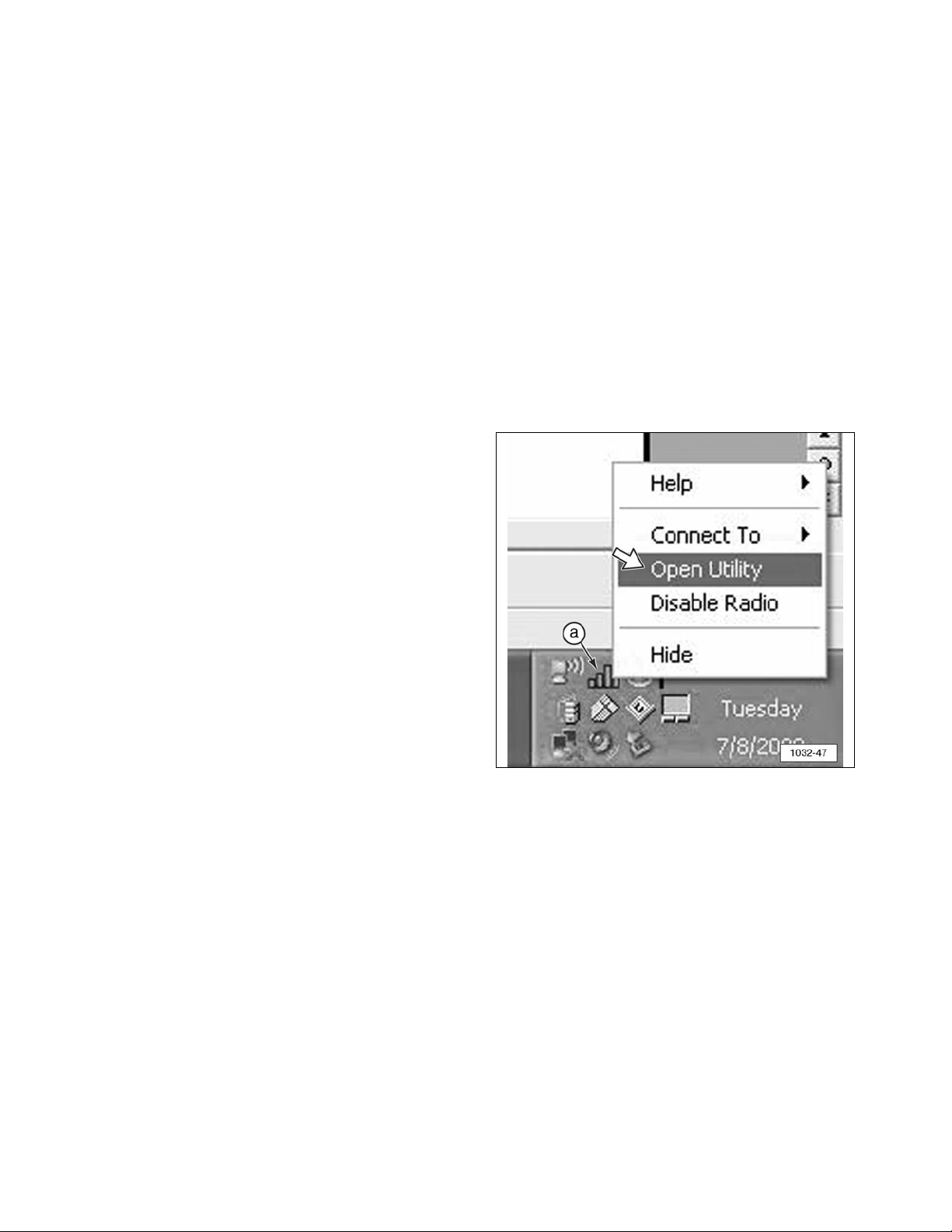
1. Open the “Client Manager Utility” for the
wireless card that is intended for use with
the W-CA3. The example shown here is for
a Dell D610 laptop. The “Client Manager
Utility” can be opened in one of two ways.
Choose one of the methods to open the
utility.
a. Right click on signal strength bars icon
(a) on the task bar. Click “Open Utility.”
(a) Signal Strength Bars.
8
Page 9

b. Go to “Start” >> “All Programs” >> “Dell
Wireless” >> “Dell Wireless WLAN Card
Utility.”
2. When the utility opens, click “Add.”
NOTE: Variations on different computers
might include the following: “New,” “New
Profile,” “Add Profile,” “Create New
Connection,” and others not listed here.
NOTE: Many wireless client utilities provide
the ability to “Scan” or “Monitor” for available
networks. In this example, there is an
“Available Networks” box that will show the
W-CA3 radio is available for connection. If
“W-CA3” is double-clicked, the “Add” menu
appears and automatically completes all of the
necessary settings, except for the security
settings. The security settings listed in the
“Configuring the PC for Communication With
the W-CA3” section can be added to complete
the profile.
9
Page 10
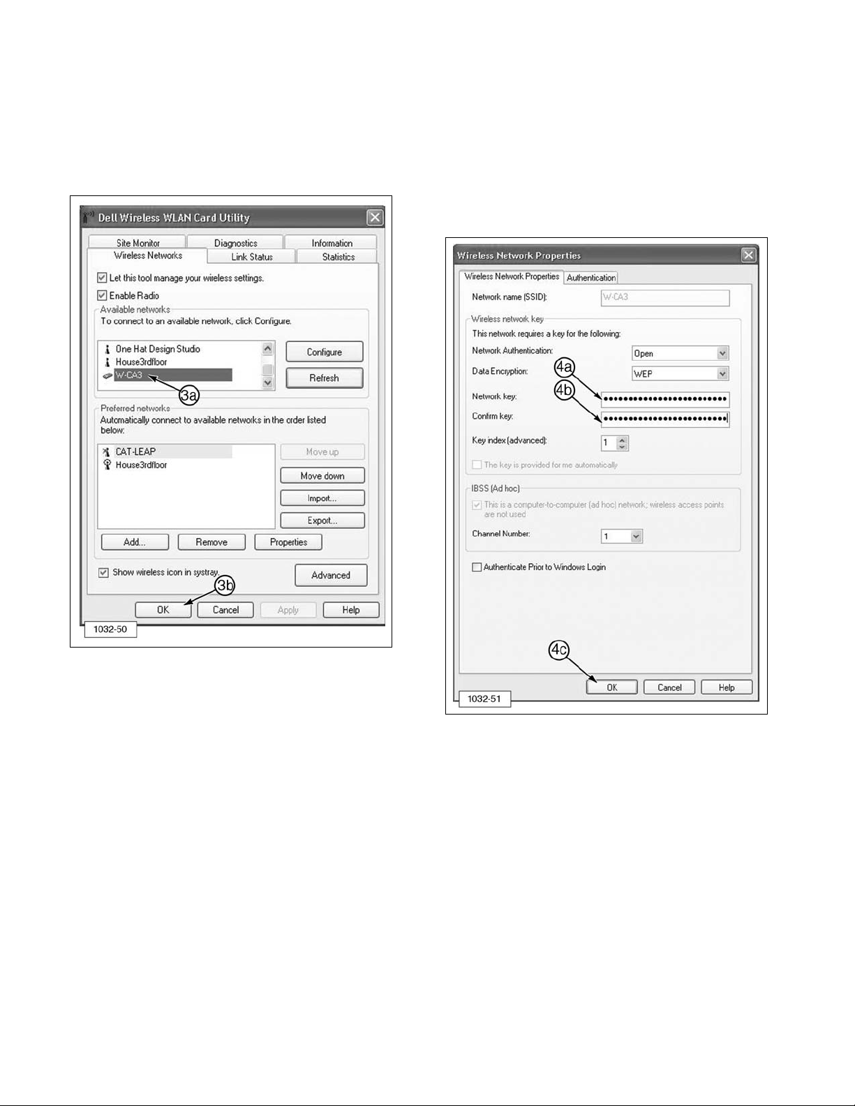
3. W-CA3 appears in the “Available Networks”
area of the Dell Wireless WLAN Card Utility
window.
a. Double-click on “W-CA3” to add.
b. When ready, click “OK.”
4. From the “Wireless Network Properties”
screen:
a. Enter 35373c57222750362a334c6a71 in
Network key field
b. Enter 35373c57222750362a334c6a71 in
Confirm key field.
c. Click “OK.”
10
Page 11
5. If the wireless client utility did not provide
the functionality described in Steps 3 and
4, proceed with the following steps. If the
utility did provide the functionality and
created the profile, proceed to Step 12.
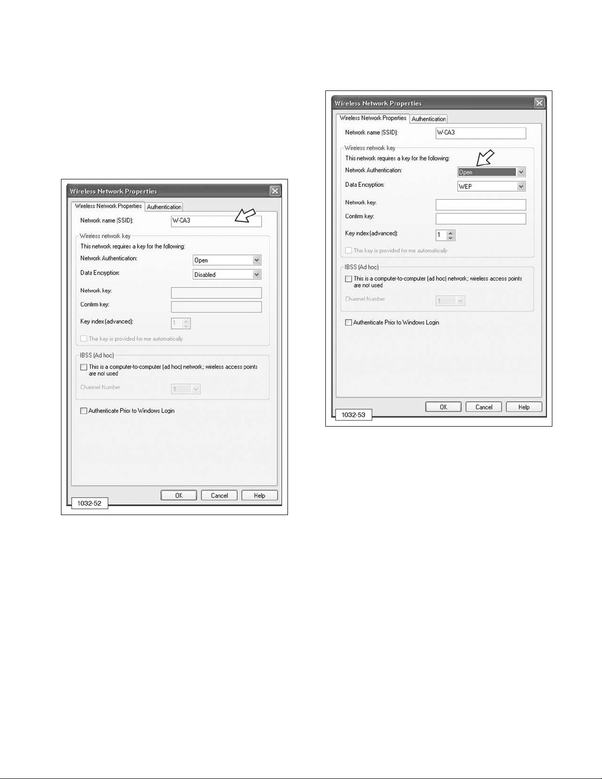
6. Enter W-CA3 into the “SSID” area of the
Wireless Network Properties window. This
is sometimes called “Network” or “Network
Name.”
7. Select “Open” for the “Network
Authentication.”
11
Page 12
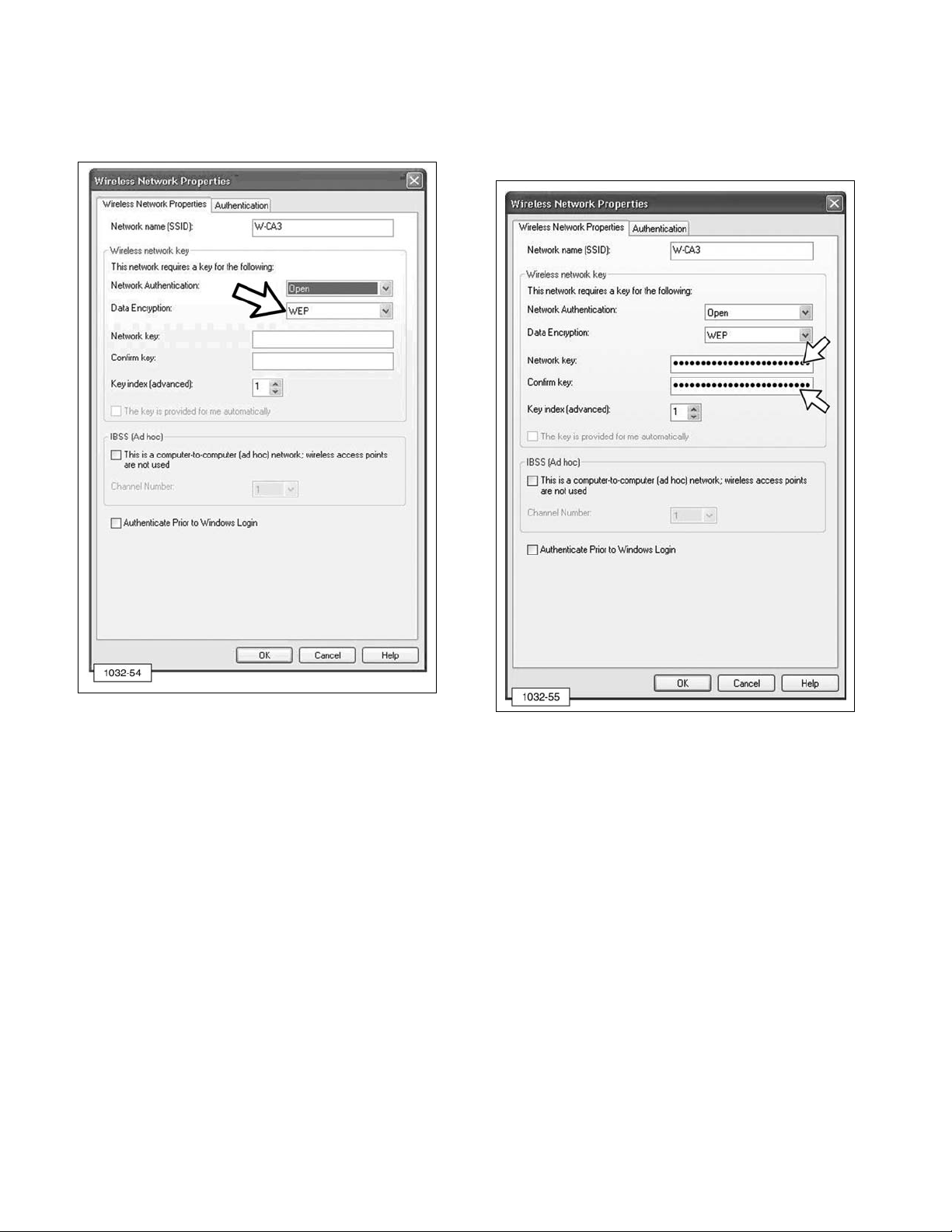
8. Select “WEP” for “Data Encryption.” This is
sometimes called “Security Type” or
“Encryption Method.”
9. Enter 35373c57222750362a334c6a71 for
“Network Key” and again for “Confirm Key.”
This is sometimes called “WEP Key,”
“Security Key,” or “Pre-Shared Key.”
NOTE: Some wireless client managers do not
accept lower case letters, so the use of capital
letters is acceptable.
12
Page 13

10. Select “This is a computer-to-computer
(ad hoc) network; wireless access points
are not used.”
11. Select 11 (eleven) for “Channel Number.”
NOTE: Consult the IT Department at the
dealership to make sure Channel 11 does not
interfere with the local wireless network that
may exist at the dealer/business.
13
Page 14
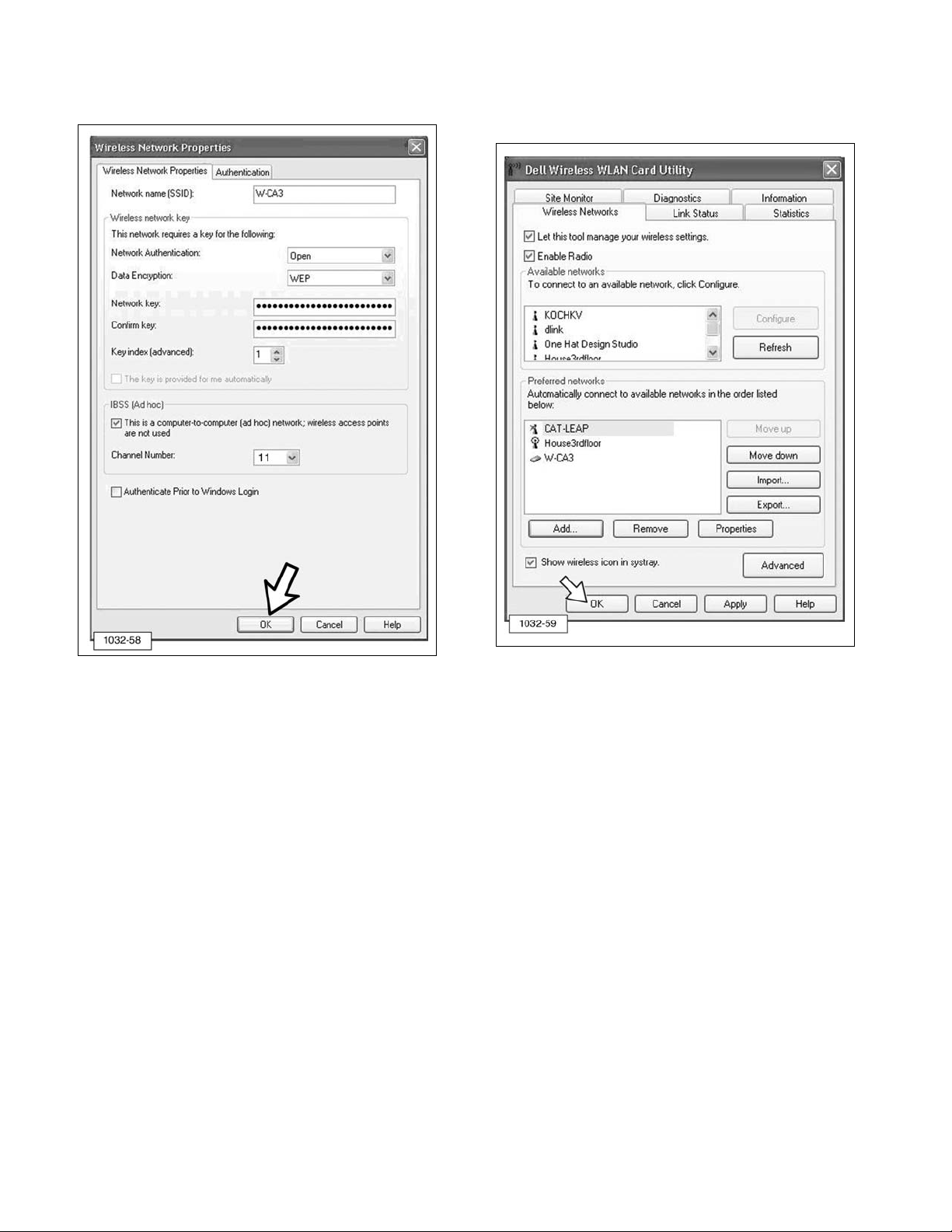
12. Click “OK” to create the profile. 13. Click “OK” again to close the wireless
client utility.
14
Page 15

14. If the wireless card is not attempting to
connect to the radio, right click on signal
strength bars (5) on the task bar and
select “Connect To” >> “W-CA3.”
NOTE: Some client utilities may not allow
connection to the radio in this manner. There
may be a “Connect” or “Activate” button
present in the client utility itself.
15. The PC should now attempt to connect to
the W-CA3 radio and an icon may display,
similar to one shown below. This icon
indicates that the PC and W-CA3 radio are
connecting to each other and configuring
their IP addresses.
NOTE: This process could take up to one
minute.
16. When the connection is complete, the
following icon will display.
NOTE: This icon (above) must appear before
attempting to connect to a machine with CAT
Electronic Technician.
17. If the mouse cursor is moved over the top
of the signal bars (do not click, just
“hover” over the top), a “Status” screen
may display showing the IP address of the
PC. The address must start with 169.254.
If it does not, the connection is not fully
established.
NOTE: This address may take approximately
15-20 seconds to update and have 169.254 at
the beginning of it. Wait until the address
updates before attempting to connect with Cat
ET.
15
Page 16
When connecting to a machine with CAT ET,
using the W-CA3 in Auto-IP mode (default
setting), it may take up to one minute for the
process to complete. Using the Auto-IP mode
is recommended.
NOTE: To use a static IP, the W-CA3 must be
configured with a static IP address and the
wireless card on the PC will also have to have
an IP address set. Advanced users should
refer to the “Changing the Internal Settings of
the W-CA3” section of this manual for
information on how to access the internal
settings of the W-CA3.
Electronic Technician Configuration for
the W-CA3
Configure Cat ET for communication through
the 317-7485 Communications Adapter 3
(CA3) and the 317-7493 Wireless USB
Radio (W-CA3).
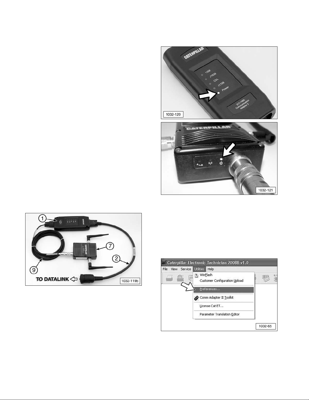
1. Use 317-8981 Cable Assembly (2) to
connect 317-7485 Communications
Adapter3 (CA3) (1) to DataLink on the
machine to be serviced. Use 317-7510
Cable Assembly (9) to connect the CA3 to
317-7493 Wireless Radio (W-CA3) (7).
(1) 317-7485 CA3. (2) 317-8981 Cable Assembly.
(7) 317-7493 W-CA3. (9) 317-7510 Cable Assembly.
The Power lights for both the CA3 and
W-CA3 should be ON.
NOTE: The other two lights on the W-CA3
may also be ON. This is acceptable. It does
not indicate a problem with the radio.
2. On the PC, open Caterpillar Electronic
Technician and go to “Utilities” >>
“Preferences.”
16
Page 17

3. The “Preferences” window will display.
a. Select “Wireless Communication
Adapter 3.”
b. Click “OK.”
4. Click the “Connect” icon
and the following dialog will display:
Saving the W-CA3 as a favorite for faster
connection later.
5. Click the “Advanced...” button to set the
specifics for the radio.
6. The “Radio Discovery” window will display
and, if the wireless network between the
radio and the PC is already established
(verify by making sure the network card is
connected to the W-CA3 and has full signal
strength), then the wireless radio should be
automatically discovered and appear on
the list. If the radio is not on the list,
proceed to Step 7. If it is on the list,
proceed to Step 10.
7. Click the “Refresh” button one or two times
to verify that the radio is not found. If the
radio is found this time, proceed to Step 9.
If it is not found, proceed to Step 8.
17
Page 18

8. Verify that the wireless card is connected
with full signal strength and that the PC has
obtained an IP address. If using the radio
with its default settings, Auto IP is enabled
and it can take up to one minute for an IP
address to be established on the PC.
When fully connected, these two icons may
appear in the task bar.
9. If the connection to the W-CA3 still cannot
be established, return to the “Configuring
the PC Wireless Card for Communication
With the Radio” section of this manual and
verify that the configuration on the PC was
performed correctly.
10. When the W-CA3 has been discovered,
make sure it is highlighted and click “Add
To Favorites” to save the W-CA3. This will
allow for easy connection to the wireless
radio at a later time.
11. When the “Favorite Radios” window
displays, the “Hostname” and
“Description” fields can be completed for
identification purposes, but it is not
required. Click “OK” and the W-CA3 will
be saved as a “Favorite” radio for
connecting at a later time.
12. Click “Close.”
13. Click “Close” again.
18
Page 19

14. The “Preferences” window will display.
a. From the drop-down menu, select the
W-CA3 that was just discovered.
b. Click “OK” to initiate an ET connection.
Activating and Changing the
Internal Settings of the W-CA3
Included in the W-CA3 is the ability for the
user to change the internal operating settings
in order to make it behave differently. For
example, the W-CA3 security key and settings
can be changed. The wireless channel or
mode can be changed, plus many other
settings, in order for the W-CA3 to be
configured to avoid interference, or to provide
compatibility with the W-CA3 and a particular
shop’s internal wireless network.
NOTE: Because of possible wireless
certification noncompliance around the world,
the W-CA3 is deactivated by default when
purchased. In order to make the W-CA3
functional, the user must perform the following
steps and configure the radio for the country
where it will be used.
Connecting the W-CA3 to a PC
Although it is possible to change the internal
settings of the W-CA3 wirelessly, it is
recommended that the radio be connected to
a PC via 317-7496 Cable Assembly (8) and
317-7510 Cable Assembly (9).
(8) 317-7496 Cable Assembly.
(9) 317-7510 Cable Assembly.
1. Connect 317-7496 Cable Assembly (8) to
317-7510 Cable Assembly (9).
(8) 317-7496 Cable Assembly.
(9) 317-7510 Cable Assembly.
19
Page 20

2. Connect 317-7510 Cable Assembly (9)
round DIN connector to W-CA3 (7) plug.
(7) 317-7493 W-CA3. (9) 317-7510 Cable Assembly.
3. Connect the USB end of 317-7496 Cable
Assembly (8) to the PC USB port.
(8) 317-7496 Cable Assembly.
4. Completed configuration.
(7) 317-7493 W-CA3. (8) 317-7496 Cable Assembly.
(9) 317-7510 Cable Assembly. (11) PC.
Installing the USB Drivers for the W-CA3
1. When the W-CA3 is connected to the PC for
the first time, the “Found New Hardware
Wizard” will display.
a. To install the drivers for the W-CA3,
select “No, not this time.”
b. Click “Next.”
c. Select “Install from a list of specific the
locations (Advanced).”
d. Click “Next.”
20
Page 21
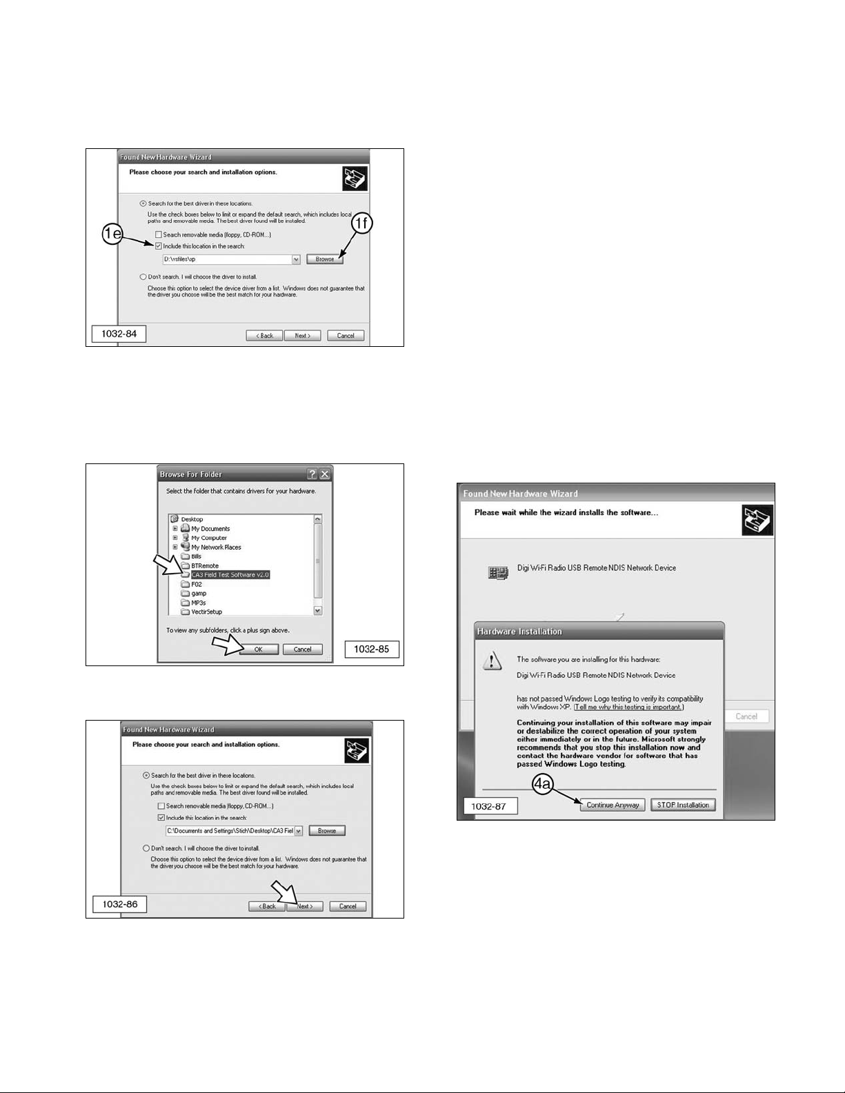
e. Select “Include this location in the
search:”
f. Click “Browse.”
2. Specify where the Hardware Wizard can
find the drivers for the radio by browsing to
the folder “W-CA3 USB Drivers.” Click
“OK.”
3. Click “Next” to install the drivers.
4. The following Hardware Installation pop-up
window message may display on the
“Found New Hardware Wizard” window:
The software you are installing for this
hardware:
DIGI Wi-Fi Radio USB Remote NDIS
Network Device
has not passed Windows Logo testing to
verify its compatibility with Windows XP.
(Tell me why this testing is important.)
Continuing your installation of this software
may impair or destabilize the correct
operation of your system either immediately
or in the future. Microsoft strongly
recommends that you stop this installation
now and contact the hardware vendor for
software that has passed Windows Logo
testing.
a. Click “Continue Anyway.”
21
Page 22

5. The message “The wizard has finished
installing the software for: Digi Wi-Fi Radio
USB Remote NDIS Network Device” will
appear. Click “Finish” to close the wizard.
Viewing/Changing the Internal Settings
for the W-CA3
IMPORTANT NOTE:
When the 317-7492 Wireless Radio Kit is
purchased, it is deactivated by default. In
order for the radio to be used and to obtain
the best performance, the 317-7493 Wireless
Radio (W-CA3) must be configured for the
country it will be used in. Perform the
following steps to select the country of use.
1. Access the W-CA3 through Cat ET.
2. Go to “Utilities” >> “Preferences.”
3. Make sure the adapter selected in the
“Preferences” window is “Wireless Comm
Adapter 3.”
4. Click “Advanced...”
5. The “Favorite Radios” window will display.
Click “Discover Radios.”
22
Page 23

6. Make sure that the radio is discovered in
the “Radio Discovery” window and click
“Web Interface.”
NOTE: Make sure that the correct adapter is
selected if more than one appears. If the
wrong adapter is selected, changes may be
made to the wrong W-CA3. Multiple radios
can appear if there are others nearby and they
might be discovered wirelessly. This can be
avoided by disabling the wireless card on the
PC while changes are being made to the
W-CA3 via the USB cable.
7. The “Enter Network Password” window will
display.
a. Type “admin” as default user name.
b. Type “wca3” as default password.
c. Click “OK.”
8. The Home Page screen will display.
9. Select “Wireless Setting” (a) from the
sidebar to display the Wireless Settings
window.
23
Page 24

10. “Location” field (b) must be configured in
order for the radio to be functional. Select
the country where the W-CA3 will be used
from the drop-down list.
NOTICE
This setting will configure the radio for the
maximum performance allowed by law for the
area that the W-CA3 will be used in. The user
is legally obligated and responsible for choosing
the correct country of use. Disregard for this
requirement is punishable by law.
11. Once the country is selected, click
“Apply” (c) at the bottom of the screen.
A note will display at the top of the screen
stating the W-CA3 must be “rebooted” for
the changes to take effect. If this is the
first time the radio has been used and no
other setting changes are desired, unplug
the radio from the PC and return to
“Install/Configure the Wireless CA3
(W-CA3) Radio.” If more setting changes
are desired, click the “Reboot” selection
on the left and then click the “Reboot”
button that appears. This applies the
country setting and allows other setting
changes to be made.
24
Page 25

Additional Settings Available for
Modification in the W-CA3
The following screens show each of the
W-CA3 setting pages and the options
available. Consult the IT Department before
making any changes to the configuration of
the W-CA3. This will ensure that the setting
chosen for the W-CA3 does not conflict with
any other wireless networks in the area.
The Home Page screen contains several
status parameters for the W-CA3. Those of
particular interest are as follows.
b. Version - The current version of the
software loaded onto the W-CA3.
c. IP Address - The current IP address
that the W-CA3 is using.
d. Temperature - The internal temperature
of the radio.
e. Up Time - The total time the W-CA3
has been powered up.
25
(b) Version. (c) IP Address. (d) Temperature. (e) Up Time.
Page 26

The Product Settings screen contains the
“Device Name” field. This field can be
changed to give the radio a unique name or
identifier.
26
Page 27

The Account Settings screen reads as follows.
Welcome to the Accounts Manager.
Please define an Admin user with a secure
password, and check the ‘Admin’
permission checkbox for that user. You
can also define a Guest User that has
read-only access to most of the information
for this device; do not check the ‘Admin”
checkbox for Guest users. The ‘Admin’
user has full access to the device, and can
perform operations that read and write
objects, such as configuration files. The
‘Guest’ user has read-only access to the
device.
The user name and password can be up to
31 characters each.
Always use secure passwords for all
accounts.
At least one ‘Admin’ account name must
be defined.
The Account Name (f) and Account Password
(g) allows multiple users to have accounts on
the W-CA3 and to log into the W-CA3
configuration individually. Only those users
who have “Admin Permission?” (h) checked
will be allowed to make changes to the
settings of the W-CA3. All others will only be
able to view the settings of the W-CA3.
Click on “Apply” (i) to accept any changes.
27
(f) Account Name. (g) Account Password. (h) Admin Permission? (i) Apply.
Page 28

The Wireless Settings screen contains the
settings that pertain to the wireless setup of
the W-CA3.
a. Location - Specifies the country where
the W-CA3 will be used. To obtain the
maximum performance from the
W-CA3, the country must be selected.
j. Network Name - This specifies the
name of the wireless network that the
W-CA3 creates in order for the PC to
connect to it.
k. Network Type - Specifies whether the
radio will connect to an internal
wireless network (infrastructure) or
directly to a PC (ad hoc).
l. Wireless Mode - 802.11 a, b, or g mode
can be chosen, or a combination of
these.
m. Data Encryption - Specifies how the
wireless data will be encrypted.
28
(a) Location. (j) Network Name (SSID). (k) Network Type. (l) Wireless Mode. (m) Data Encryption.
Page 29
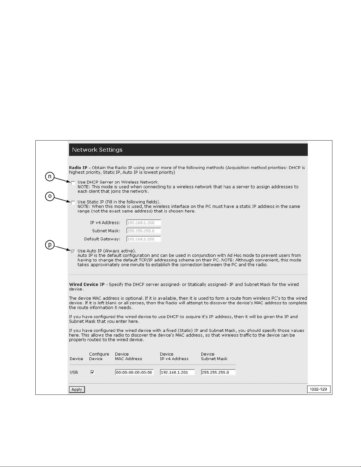
The Network Settings screen allows the user to
specify how the radio will obtain an IP
address. If more than one of these settings is
enabled, the radio will acquire the IP address
in the following order.
n. DHCP - Obtains an IP address from a
server located on a local wireless
network.
o. Static IP - Allows the user to specify
the exact address the W-CA3 will use.
p. Auto IP - The W-CA3 will use an
address in the Auto IP range
(169.254.x.x).
29
(n) Use DHCP Server on Wireless Network. (o) Use Static IP (Fill in the following fields). (p) Use Auto IP (Always active).
Page 30

The “Temperature Monitor Parameters” screen
allows the user to specify the operating
temperature limits that will cause temperature
changes to be recorded in the log file.
The “Log File Management” screen allows the
user to view the log files which contain
debugging information relating to the
operation of the W-CA3.
30
(q) Temperature Unit. (qf) Fahrenheit (use Fahrenheit Scale). (qc) Celsius (use Celsius Scale). (r) Log Enable.
(s) Low Temperature. (t) High Temperature. (u) Apply.
(v) Log Directory Contents. (w) Name. (x) Type. (y) Size.
Page 31
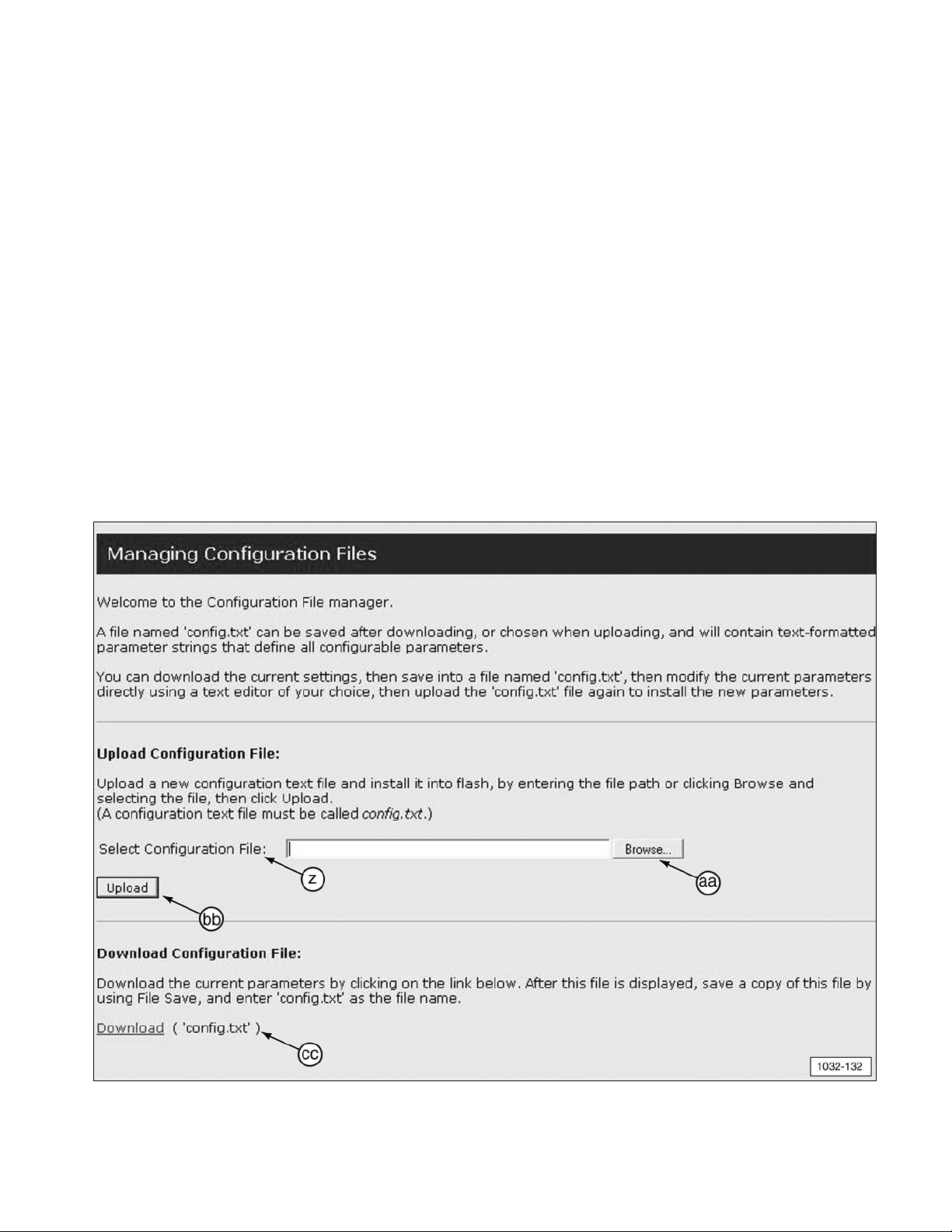
The “Managing Configuration Files” screen
reads as follows.
Welcome to the Configuration File
manager.
A file named ‘config.txt’ can be saved after
downloading, or chosen when uploading,
and will contain text-formatted parameter
strings that define all configurable
parameters.
You can download the current settings,
then save into a file named ‘config.txt’,
then modify the current parameters directly
using a text editor of your choice, then
upload the ‘config.text’ file again to install
the new parameters.
Upload Configuration File
:
Upload a new configuration text file and
install it into flash, by entering the file path
or clicking Browse and selecting the file,
then click Upload.
(A configuration text file must be called
config.txt.)
Download Configuration File
::
Download the current parameters by
clicking on the link below. After this file is
displayed, save a copy of this file by using
File Save, and enter ‘config.txt’ as the file
name.
NOTE: The “Managing Configuration Files”
screen allows for the current configuration of
the radio to be downloaded and uploaded to
another W-CA3 to save time when configuring
multiple W-CA3 with the same settings.
31
(z) Select Configuration File. (aa) Browse. (bb) Upload. (cc) Download (‘config.txt’).
Page 32

The “Upload Firmware” screen allows new
firmware for the W-CA3 to be loaded into the
internal memory of the unit. This screen reads
as follows.
Upload a new firmware or ROM image into
flash.
“(A firmware image file must be called
image.bin. A ROM image file must be
called rom.bin.)
(aa) Browse. (bb) Upload. (dd) Select Image.
The “Reboot” screen reads as follows.
Click Reboot to reboot this device.
This screen allows the user to reboot the
W-CA3 through software. This is the same as
power-cycling the W-CA3. Any time settings
are changed in the radio and applied, the
W-CA3 must be rebooted for the settings to
become active.
(cc) Reboot.
32
Page 33
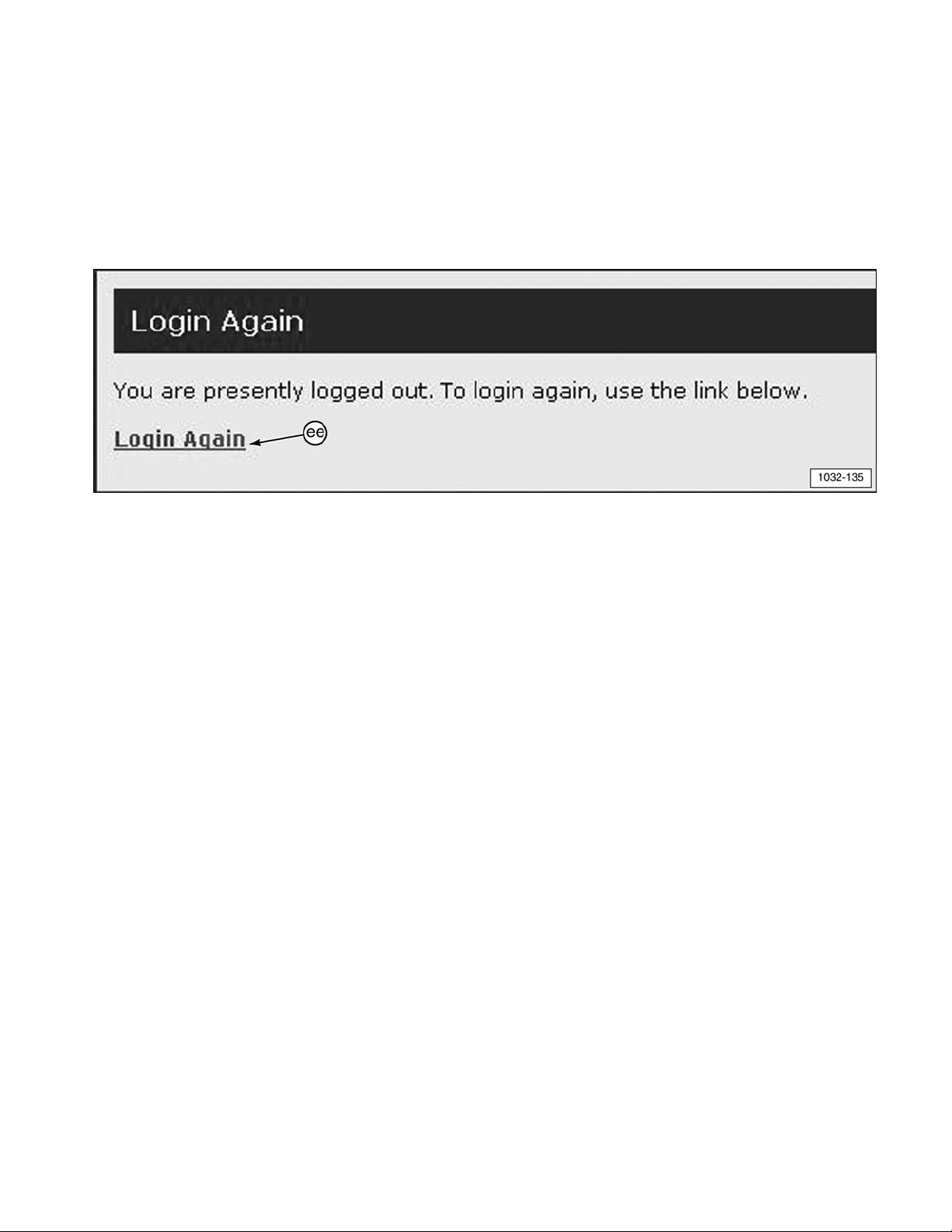
The “Login Again” screen reads as follows.
You are presently logged out. To login
again, use the link below.
This screen displays when the user clicks
“Logout” on the shortcuts list at the left side of
the Home Page screen. The current user will
be logged out, which allows another user to
log in.
(ee) Login Again.
33
Page 34

Tooling Configurations
There are several options for configuring the
317-7493 Wireless Radio (W-CA3) for various
functions and uses.
IMPORTANT NOTE:
To comply with US and Canadian regulatory
requirements, read, understand, and follow
the guidelines in the Regulatory Information
section in this manual when configuring
and operating the 317-7493 Wireless Radio
(W-CA3) and related components.
If the machine is required to work
within 12 m (40 ft) of a blast area,
the operator must disable and
remove the 317-7492 Wireless
Radio. Failure to do so could result in
serious injury or death.
NOTE: For more information on connecting
the W-CA3, refer to specific sections in this
manual.
W-CA3 to PC
(7) 317-7493 W-CA3 connected to PC (11) USB port with
317-7496 Cable Assembly (8) and 317-7510 Cable
Assembly (9) (for configuring the wireless radio).
W-CA3 to CA3 to DataLink
(7) 317-7493 Wireless Radio (W-CA3) connected to
317-7485 Communications Adapter3 (CA3) (1) with
317-7510 Cable Assembly (9). Ready for connection to
DataLink with 317-8981 Cable Assembly (2).
Magnetic Mount W-CA3 to CA3
Magnetically attach W-CA3 (7) onto the back side of
317-7485 CA3 (1). (2) 317-8981 Cable Assembly.
(9) 317-7510 Cable Assembly.
34
WARNING
Page 35

Using the Remote Antenna
The 326-9607 Remote Antenna enables better
“line of sight” antenna placement for W-CA3
communication with a remote PC. It features a
magnetic base for temporary mounting on
equipment.
1. Unthread (counterclockwise) fitting and
remove standard 326-9606 Antenna (7a) on
the side of 317-7493 Wireless Radio
(W-CA3) (7) closest to the “C” in the
CATERPILLAR label displayed on the front
of the radio. Save the removed antenna for
reuse.
317-7493 Wireless Radio (W-CA3) (7).
326-9606 Antenna (7a).
2. Thread (clockwise) the connector fitting of
optional 326-9607 Remote Antenna (11)
onto 317-7493 Wireless Radio (W-CA3) (7)
finger tight.
(11) 326-9607 Remote Antenna (optional).
NOTE: For wireless communication to
function, the W-CA3 antenna(s) must have
“line of sight” with the dealer supplied PC.
Place the magnetic base of the remote
antenna on a metal surface high up on the
machine, away from any heat source.
Using the Suction Cup Mount
Optional 317-7512 Suction Cup Mount (10)
allows placement of the magnetic 317-7493
Wireless Radio (W-CA3) (7) on a nonmetallic
surface, such as the window of a cab.
(7) 317-7493 Wireless Radio (W-CA3).
(9) 317-7510 Cable Assembly. (10) 317-7512 Suction
Cup Mount.
1. Place suction cup mount (10) on a clean,
dry, flat surface, away from any heat
source. Pump the white plunger several
times to adhere the mount to the surface.
(10) 317-7512 Suction Cup Mount (pump plunger).
35
Page 36

2. The mount is secure when the RED line on
the plunger is no longer visible.
(10) 317-7512 Suction Cup Mount (red line on plunger
not visible).
3. To release the suction cup mount, support
the mount and firmly push inward (toward
the center) on either one of the soft tabs
near the suction cup edge.
(10) 317-7512 Suction Cup Mount (release tabs).
NOTICE
Monitor the 317-7512 Suction Cup Mount during
use. To avoid damage to the W-CA3, suction
cup mount, and/or related components, do not
leave unattended.
Service Parts Section
317-7492 Wireless Radio Group
317-7512 Suction Cup Mount
317-7492 Wireless USB Radio (W-CA3) Kit
Item Part No. Description Qty
7 317-7493 Wireless Radio Group (W-CA3) 1
7a 326-9606 Antenna 2
8 317-7496 WiFi/USB PC Cable Assembly 1
9 317-7510 WiFI/CA3 Cable Assembly 1
317-7512 Suction Cup Mount (Optional)
Item Part No. Description Qty
10 317-7494 Suction Cup Mount 1
36
Page 37

326-9607 Remote Antenna
326-9607 Antenna (Optional)
Item Part No. Description Qty
11 326-9607 Remote Antenna 1
NOTE: At the end of the tools operational life,
destroy the component. Recycle electrical
equipment according to all Federal, state, and
local guidelines.
Related Components
317-7484 Communications Adapter3
(CA3) Group
The 317-7493 Wireless Radio is designed to
be used with 317-7484 Communications
Adapter 3 and related components. For
reference, this tooling is shown here.
NOTE: For more information on the
317-7484 Communications Adapter 3, refer to
NEHS1032 Tool Operating Manual.
317-7484 Communications Adapter 3 (CA3) Group
Item Part No. Description Qty
1 317-7485 Communications Adapter 3 (CA3) 1
2 317-8981 CA3/DataLink Cable Assembly 1
3 317-7487 CA3/PC Cable Assembly 1
4 6V-7145 Case 1
4a 317-7513 Foam Insert Assembly 1
— NETG5057 Media CD 1
— NEHS1032 Tool Operating Manual 1
37
Page 38

Regulatory Information
Section
NOTE: Changes or modifications not
expressly approved by the party responsible
for compliance could void the user’s authority
to operate the equipment.
Regulatory Information And
Certifications
RF Exposure Statement
Caterpillar 802.11 a/b/g Radio complies with
the RF exposure limits for humans as called
out in the FCC guidance for Specific
Absorption Rate (SAR).
IMPORTANT NOTE:
To comply with FCC RF exposure compliance
requirements, the antenna used for this
transmitter must be installed to provide a
separation distance of at least 20 cm (7.9 in)
from all persons and must not be co-located or
operating in conjunction with any other
antenna or transmitter. OEM installers must
consider suitable module and antenna
installation locations in order to assure this
20 cm (7.9 in) separation, and end users must
be also be advised of the requirement.
FCC Certifications
These devices comply with part 15 of the FCC
rules. Operation is subject to the following two
conditions:
• These devices may not cause harmful
interference.
• These devices must accept any
interference received, including
interference that may cause harmful
operation.
Radio Frequency Interference
(RFI) (FCC 15.247 and 15.407)
This equipment has been tested and found to
comply with the limits for digital devices
pursuant to Part 15 of the FCC Rules. These
limits are designed to provide reasonable
protection against harmful interference in
automotive environments. This equipment
generated, uses and can radiate radio
frequency energy, and if not installed and
used in accordance with the instruction
manual, may cause harmful interference to
radio communications. However, there is no
guarantee that interference will not occur in a
particular installation. If this equipment does
cause harmful interference to other equipment,
which can be determined by turning the
equipment off and on, the user is encouraged
to try and correct the interference by one or
more of the following measures:
• Reorient or relocate the receiving antenna
• Increase the separation between the
equipment and the receiver.
• Consult the dealer or an experienced
technician for help.
IMPORTANT NOTE:
To comply with US and Canadian regulatory
requirements, when the 317-7493 Wireless
Radio is used outdoors, the channels in the
band 5150-5250 MHz must be disabled.
Users are cautioned to take note that
high-power radars are allocated as primary
users (meaning they have priority) of the
bands 5250-5350 MHz and 5650-5850 MHz.
The 317-7493 Wireless Radio complies with
IEEE 802.11h - Spectrum Managed 802.11a
(5 GHz) devices. Therefore, the use of these
two bands will enable Dynamic Frequency
Selection (DFS) in which the detection of radar
and spectrum management of either an
Infra-Structure or Ad hoc network is automatic.
38
Page 39

Industry Canada
This digital apparatus does not exceed the
limits for radio noise emissions set out in the
Radio Interference Regulations of the
Canadian Department of Communications.
Le present appareil numerique n’ement pas de
bruits radioelectriques depassant les limites.
A prescrites dans le Reglement sur le
brouillage radioelectrique edicte par le
ministere de Communications du Canada.
IMPORTANT NOTE:
To comply with RSS-210 section A9.2(2)
E.I.R.P. limits, the maximum antenna gain
permitted in the bands 5250-5350 MHz and
5470-5725 MHz is:
250mW conducted power - 1.0W max E.I.R.P.
To comply with RSS-210 section A9.2(3)
E.I.R.P. limits, the maximum antenna gain
permitted in the bands 5725-5825 MHz is:
1W conducted power - 4.0W max E.I.R.P.
The 326-9606 Antenna and 326-9607 Remote
Antenna meet these requirements.
Statement To Original Equipment
Manufacturer (OEM) Integrators
This device is intended only for OEM
integrators under the following conditions:
• The antenna must be installed such that
20 cm (7.9 in) is maintained between the
antenna and users for all installations.
• The transmitter module may not be colocated with any other transmitter or
antenna.
NOTE: In the event that any of these
conditions can not be met (for example
portable configurations, co-location with
another transmitter, or use of a different
antenna), then the FCC authorization is no
longer considered valid and the FCC ID can
not be used on the final product.
In these circumstances, the OEM integrator
will be responsible for reevaluating the end
product (including the transmitter) and
obtaining a separate FCC authorization.
39
Page 40

40
©2009 Caterpillar NEHS1081
All Rights Reserved Printed in U.S.A.
For information on service tools or shop supplies,
contact Dealer Service Tools on:
Dealer Service Tools
501 S. W. Jefferson
Peoria, IL U.S.A. 61630-2125
U.S.A.: 1-800-542-8665
Illinois: 1-800-541-8665
Canada: 1-800-523-8665
World: 1-309-675-6277
Fax: 1-309-494-1355
dealerservicetool_hotline@cat.com
 Loading...