

Diggity Designs XLR8 V1, XLR8 V2 Owner's Manual
STEP 1
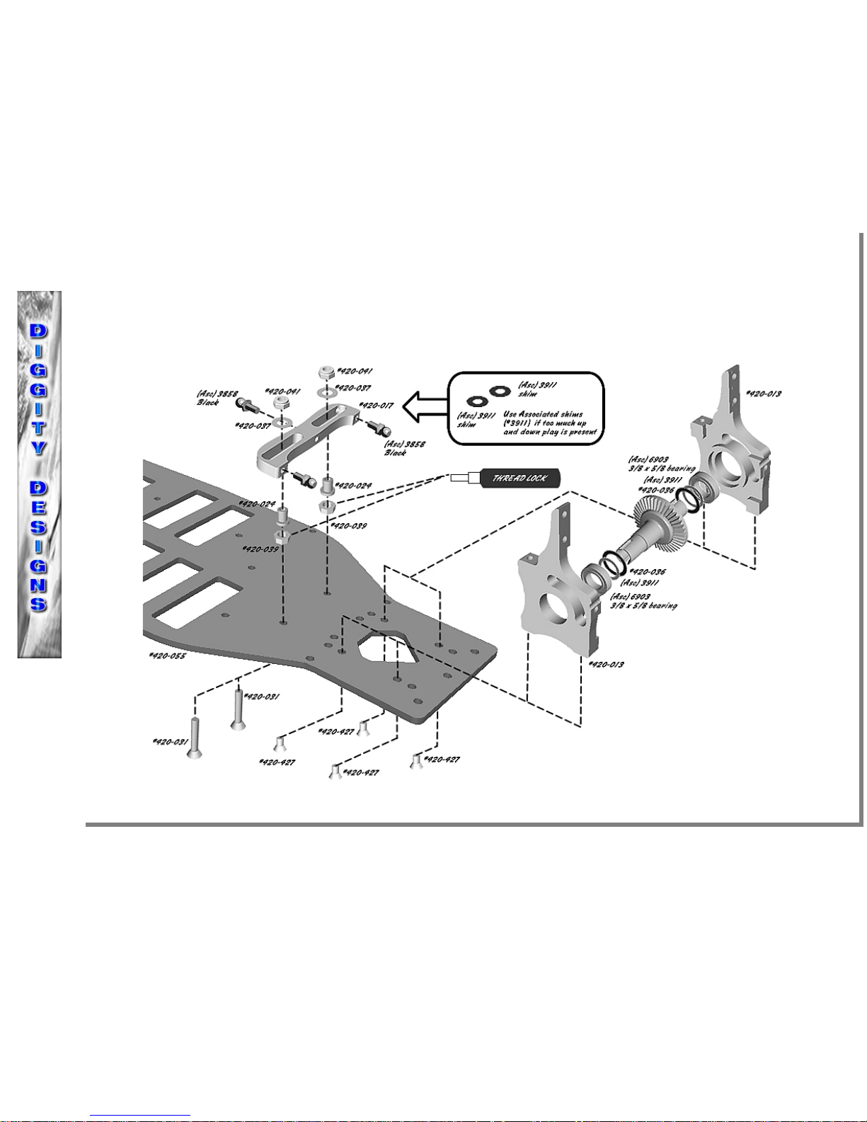
1) Assemble the steering rack (#420-017) using two 3mm x 20mm flat head stainless screws (#420-031), two 3mm nuts (#420-039), two
steering bushings (#420-024), two 3mm washers (#420-037), and two 3mm lock nuts (#420-041). You will want to tighten the lock nuts all the
way. Use the existing black ball ends from your TC3 or TC4 (#3858) and attach to the steering rack. NOTE: If the rack is binding make sure
the two 3mm x 20mm flat head screws are not off center; you can use Assoc (#3911) black shims to take any up and down play out.
2) Assemble the front differential housings (#420-013) as shown. You will want to start with one stock Associated diff shim (#3911) and one
Diggity Designs diff shim (#420-036) on both sides of the differential. You will make the proper adjustments later if needed. Using four 4-40
x 1/4 flat head stainless screws (#420-427) secure the left and right side differential housings. DO NOT FULLY TIGHTEN
STEP 1
UPDATE!!
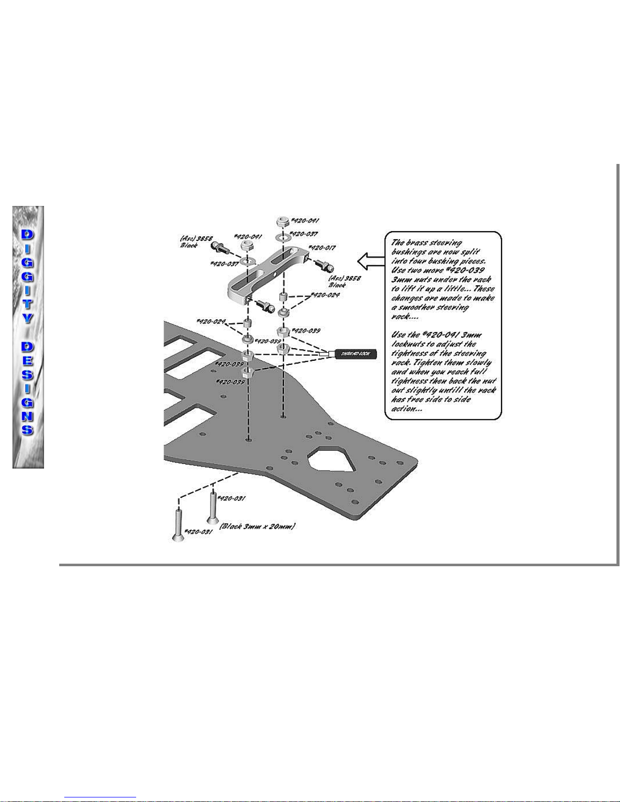
Steering rack update! Some people have had binding problems with their steering guide bushings. To take care of this problem the one piece
brass steering guide bushings #420-024 are now split in to two parts making four brass steering guide bushings. This allows for the steering
guide bushings to move against eachother more freely (if binding occurs, use a little oil or lube for the first run to break the bushings in). We
now use four #420-039 3mm hex nuts under the steering rack, this will raise your steering rack and get rid of bump steer.
STEP 2
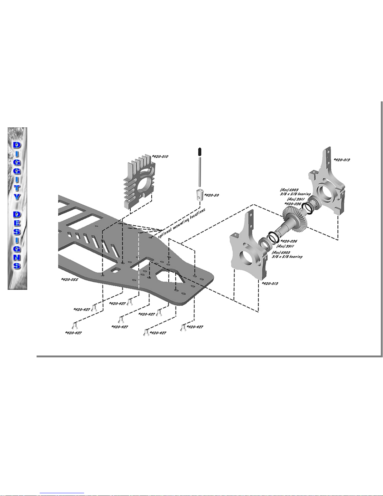
1) Assemble the rear differential housings (#420-013) as shown. You will want to start with one stock Associated diff shim (#3911) and one
Diggity Designs diff shim (#420-036) on both sides of the differential. You will make the proper adjustments later if needed. Using four 4-40 x
1/4 flat head stainless screws (#420-427) secure the left and right side differential housings. DO NOT FULLY TIGHTEN .
2) Attach the motor mount (#420-010) to the chassis using two 4-40 x 1/4 flat head stainless screws (#420-427) DO NOT FULLY TIGHTEN.
Attach the aluminum antenna mount (#420-50) to the chassis using one 4-40 x 1/4 flat head stainless screw (#420-427). There are four
mounting holes for the antenna mount depending on radio equipment location.
STEP 3
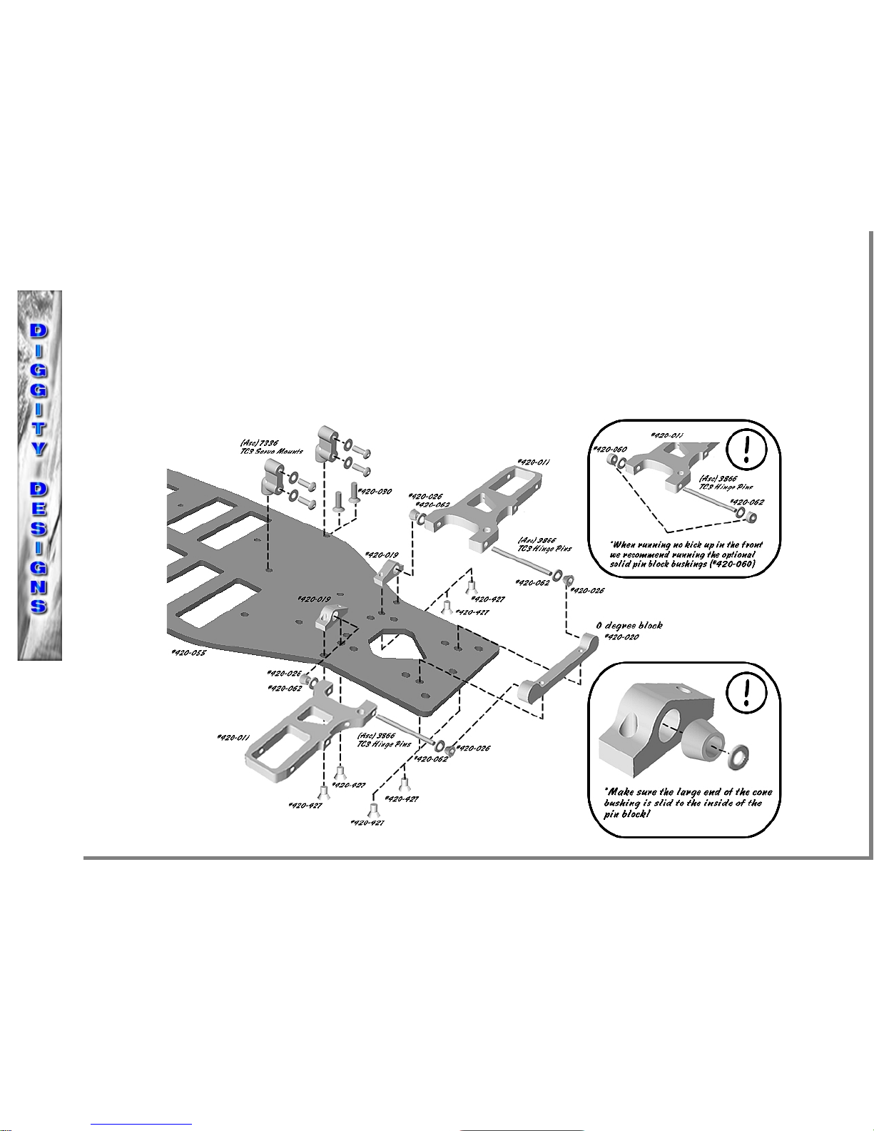
1) Attach the front inner pin blocks (#420-019) using four 4-40 x 1/4 flat head stainless screws (#420-427) to secure them to the chassis DO
NOT FULLY TIGHTEN. NOTE: You will use two 3mm x 8mm flat head stainless screws (#420-030) to attach the servo mounts.
2) Slide the stock Associated hinge pins (#3866) through the aluminum front arms (#420-011). You will use one brass swivel bushing(#420-
026) and one brass washer (#420-062) on each end of the hinge pin as shown. Make sure the brass swivel bushings (#420-026) are on correctly
shown in the box below NOTE: you might need to press the bushings on using a light hammer. Slide the front arms (#420-011) into the inner
hinge pin blocks (#420-019) first and then finish the assembly by sliding the 0 degree pin block (#420-020) onto the other end of the hinge pins
and secure to the chassis using two 4-40 x 1/4 flat head stainless screws (#420-427). DO NOT FULLY TIGHTEN
Brass Hinge Pin spacer washers! There will either be 8 thin brass spacer washers or 4 (white or black) delrin washers included in your kit. If
binding occurs when using the delrin washers you will need to sand them with sandpaper to thin them slightly, this will make sure the arms are
free from binding.
Delrin Cone Bushings! These are included for quick replacements of the brass cone bushings.
STEP 4
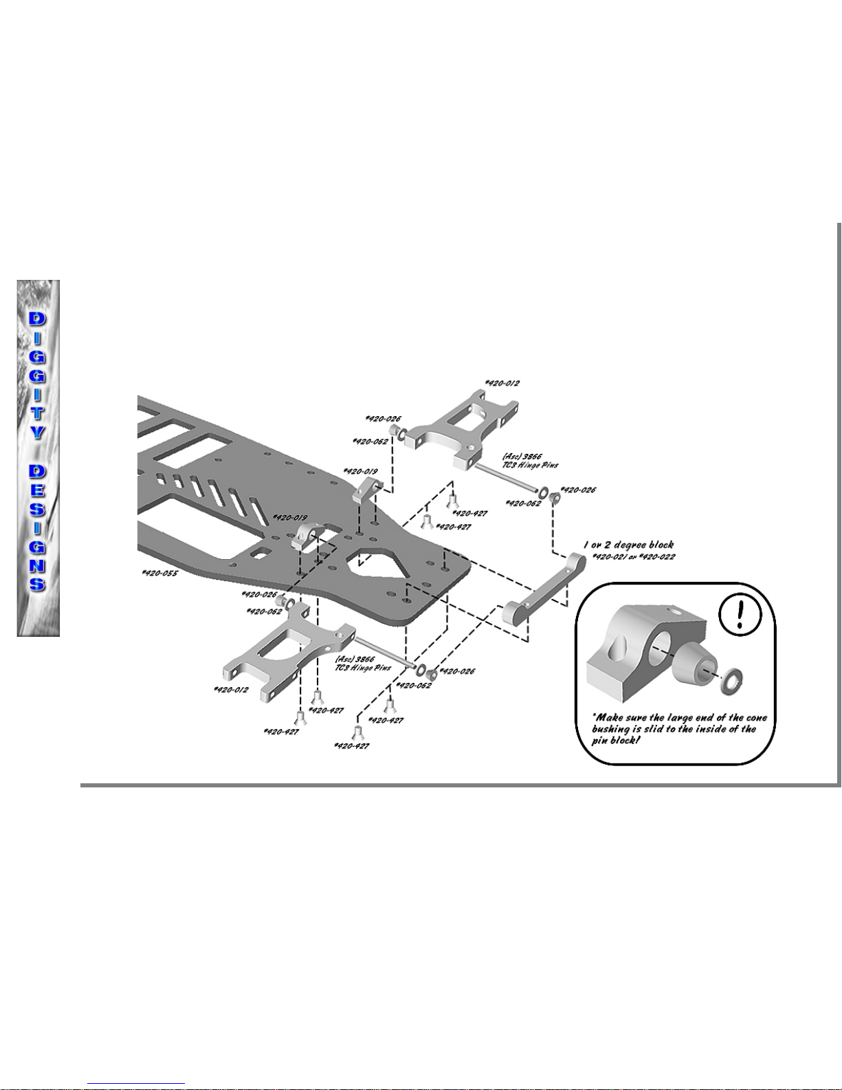
1) Attach the rear inner pin blocks (#420-019) using four 4-40 x 1/4 flat head stainless screws (#420-427) to secure them to the chassis DO
NOT FULLY TIGHTEN.
2) Slide the stock Associated hinge pins (#3866) through the aluminum rear arms (#420-012). You will use one brass swivel bushing (#420-
026) and one brass washer (#420-062) on each end of the hinge pin as shown. Make sure the brass swivel bushings (#420-026) are on correctly
shown in the box below NOTE: you might need to press the bushings on using a light hammer. Slide the rear arms (#420-012) into the inner
hinge pin blocks (#420-019) first and then finish the assembly by sliding the 1 or 2 degree pin block (#420-021 or #420-022) onto the other end
of the hinge pins and secure to the chassis using two 4-40 x 1/4 flat head stainless screws (#420-427). DO NOT FULLY TIGHTEN
STEP 4
UPDATE!
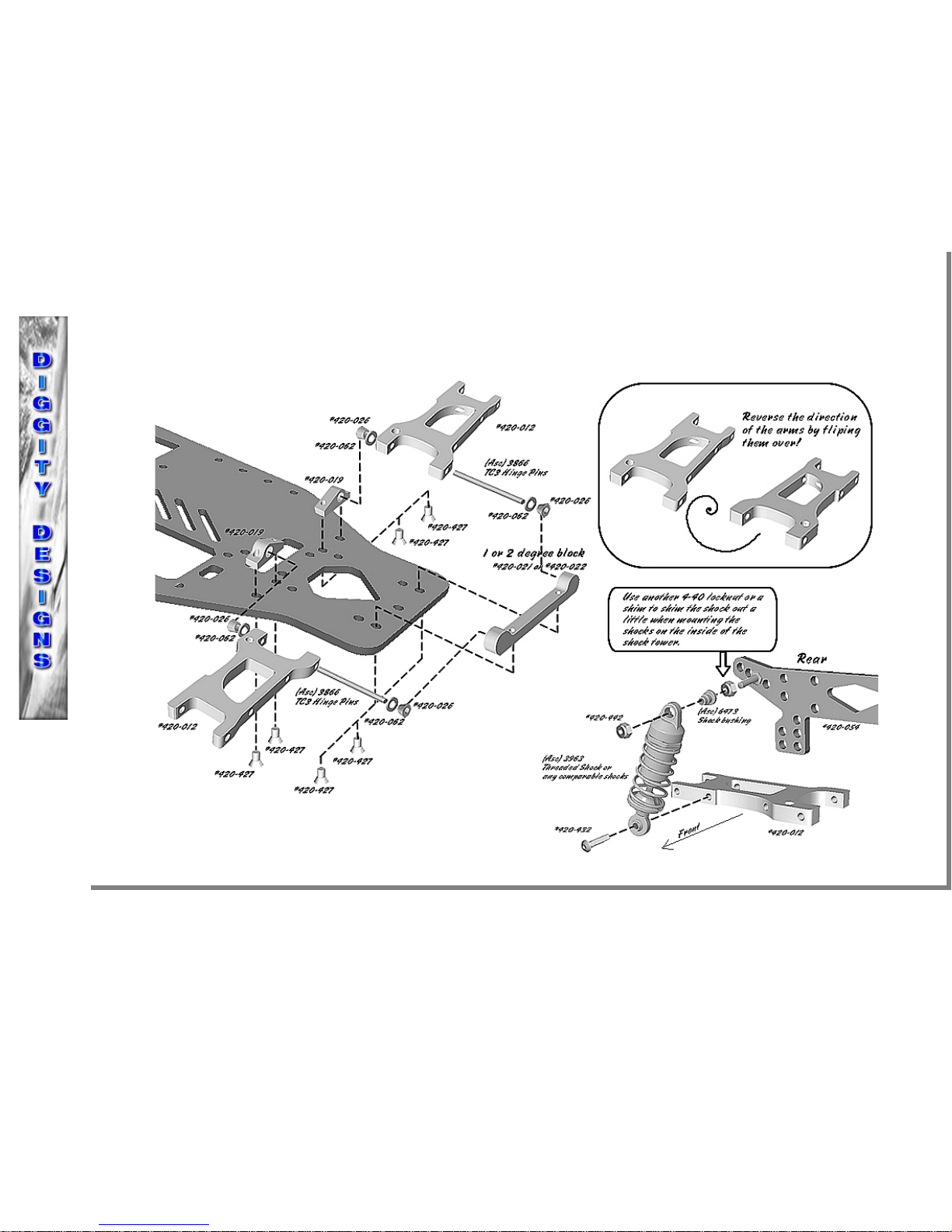
OPTIONAL! Rear arms Reverse mounting! In the most recent runnings of the XLR8 kits, racers running indoor on carpet prefer to run the
arms in reverse with the shocks on the inside of the arms. This allows for faster transitioning through tight and quick corners. Make sure to
use a spacer on the top shock mounting screw to slide the shock out more to level. (It will not be level, it will angle back at the top).
TC4 Front Steering Blocks and rear carriers: We have also noticed in the most recent runnings of the XLR8 that the TC4 front steering blocks
have an extra hole for the steering ackermann and this new mounting location works very well for the XLR8. When running the rear arms in
reverse we like to use the TC4 rear hub carriers but you will need to drill a hole for a set screw like the TC3 ones. We also recommend trying
Losi front C-hubs and rear hub carriers. Aluminum C-hubs and steering blocks give you the most solid platform.
 Loading...