

Page 1

Models 600 / 850
Series A - D Compressor Dehydrator
Instruction and operation manual
IB - 268 Rev. I Part Number 48248
Page 2
Notes, Cautions, and Warnings herein this manual
are used to prevent personal injury.
Warning: To reduce the risk of fire or electric shock, do not expose this equipment to rain or mois-
ture. For Indoor use only.
Warning: If the equipment is used in a manner not specified herein, the protection provided by the
equipment may be impaired.
Warning: Turn off Power, Isolate power by unplugging or by locking separate disconnect before
servicing.
Warning!: High Voltage Disconnect Power before working within
Caution: This Unit may start automatically at any time
NOTE: All machinery must be fitted with means to isolate it from electrical energy sources. The isola-
tor must be capable of being locked, when the operator is unable from any of the points to which
he/she has access, to check that the energy is off!
Caution: Use care when lifting compressor as compressor weight exceeds 12.3 lbs. ( 5.6 kg)
ATTENTION: Observe Precautions for Handling Electrostatic Sensitive Devices
Important Safety Instructions
1. Read and follow all instructions
2. Keep these instruction with the equipment
3. Heed all warnings, cautions and notes.
4. Do not block any ventilation openings.
5. Install in accordance with SPX Dielectric instructions
6. Do not defeat the safety purpose of the grounding type plug
7. Protect the power cord from being walked on or pinched.
8. Use Wrist Strap when handling ESD Sensitive Circuit Boards
WARNING! Risk of Electrocution
Isolate power by unplugging or by locking separate disconnect.
CAUTION - REFER TO ACCOMPANYING
WARNING - RISK OR ELECTROCUTION
WARNING - HOT SURFACE
DOCUMENTS
ATTE NTION - ELECTROSTATIC SENSITIVE
DEVICE
OBSERVE PRECAUTIONS FOR HANDLING
CAUTION - LIFTING HAZARD
PROTECTIVE CONDUCTOR TERMINAL
Page 3

TABLE I
TABLE OF CONTENTS
SECTION TITLE PAGE
1.0 INTRODUCTION 1
1.3 Before Installing 1
2.0 PRINCIPLE of OPERATION 1
3.0 SITE REQUIREMENTS 3
4.0 INSTALLATION 3
5.0 STARTUP OF THE MODEL 600 AND 850 3
6.0 ADJUSTMENTS 4
6.1 Outlet Pressure Regulator Adjustment 5
6.2 Back Pressure Regulator Adjustment 5
6.3 Outlet Pressure Alarm Switch Adjustment 5
6.4 Start / Stop Pressure switch Adjustment 5
7.0 MAINTENANCE 5
8.0 COMPRESSOR MAINTENANCE 6
9.0 TROUBLE SHOOTING 6
9.1 Outlet Air Pressure Alarm 6
9.2 Humidity Alarm 6
9.3 Excess Run Alarm 7
10.0 SERV ICE INFORMATION 7
LIST of TAB LES
TABLE DESCRIPTION PAGE
I TABLE OF CONTENTS i
II TABLE OF LEADING PARTICULARS ii
III MODEL 600 & 800 OPTION DESIGNATIONS iii
IV LIST OF COMMON SPARE PARTS 13
V LIST OF PARTS ON ALL MODELS 14
VI GLOSSARY OF TERMS 22
LIST OF ILLUSTRATIONS
FIGURE DESCRIPTION PAGE
1 DRY- PAK CYCLE 2
2 FLOW SCHEMATIC MODEL “A” DRYERS 8
3 FLOW SCHEMATIC MODEL “B” DRYERS 9
4 FLOW SCHEMATIC MODEL “C” & “D” DRYERS 10
5 FRONT VIEW 11
6 FRONT VIEW (COVER REMOVED) 11
7 SIDE VIEW (COVER REMOVED) 12
8 BACK VIEW 12
9 DESICCANT DRYER ASSY. 14
10 SOLENOID VALVE EXPLODED VIEW 15
11 COMPRESSOR - EXPLODED VIEW 15
12 “A” SERIES 115V WIRING SCHEMATIC 16
13 “A” SERIES 230V WIRING SCHEMATIC 17
14 “B” SERIES 115V WIRING SCHEMATIC 18
15 “B” SERIES 230V WIRING SCHEMATIC 19
16 “C & “D”” SERIES 115V WIRING SCHEMATIC 20
17 “C & “D”” SERIES 230V WIRING SCHEMATIC 21
i
Page 4

Tab le II
TABLE OF LEADING PARTICULARS
CHARACTERISTIC MODEL 600 A to D MODEL 850 A to D
NORMAL CAPACITY
EMERGENCY CAPACITY
WEIGHT
ELECTRICAL OPTIONS
AIR COMPRESSOR SIZE
COMPRESSOR CIRCUIT PROTECTION
CONTROL CIRCUIT PROTECTION
600 SCFD
750 SCFD
85 LBS
115VAC, 5.5A 50/60Hz 1ph
208-230VAC, 2.5A 60Hz 1ph
220-240VAC, 3.3A 60Hz 1ph
1/4 HP Piston
10 Amps(115V) 5 Amps(230V)
0.8 Amps(115V) 0.5 Amps(230V)
850 SCFD
1080 SCFD
85 LBS
115VAC, 6.5A 50/60Hz 1ph
208-230VAC, 2.7A 60Hz 1ph
220-240VAC, 3.5A 60Hz 1ph
1/4 HP Piston
10 Amps(115V) 5 Amps(230V)
0.8 Amps(115V) 0.5 Amps(230V)
DRY AIR DEWPOINT . . . . . . . . . . . . . . . .
DESICCANT DRYER TYPE . . . . . . . . . . .
OPERATING PRESSURE . . . . . . . . . . . . .
TANK PRESSURE RANGE . . . . . . . . . . .
AIR COMPRESSOR TYPE . . . . . . . . . . . .
REGULATED LINE PRESSURE . . . . . . .
HUMIDITY ALARM . . . . . . . . . . . . . . . . .
LOW LINE PRESSURE ALARM . . . . . . .
HIGH LINE PRESSURE ALARM . . . . . .
EXCESS RUN ALARM . . . . . . . . . . . . . . .
POWER ALARM . . . . . . . . . . . . . . . . . . . .
CABINET DIMENSIONS . . . . . . . . . . . . .
AIR TANK . . . . . . . . . . . . . . . . . . . . . . . . .
AIR TANK RELIEF VA LVE . . . . . . . . . . .
Below -40°F. (below -40°C.)
DRY-PAK® twin-tower heatless dryer. Efficient, internal check-ball valving, purge controlled by Four-way solenoid valves.
DRY-PAK® and compressor 45 PSIG (310 kPa), independent of tank pressure.
20 PSIG (137 kPa) (compressor start) to 45 PSIG (310 kPa) (compressor stop).
Piston oilless
Adjustable 2 TO 15 PSIG (14 - 103 kPa) on Models A,B, and C
Adjustable 0.1 TO 2.0 PSIG (0.7 - 14 kPa) on Models D
Color Change Humidity Indicator on Model A
Solid state Humistat on Models B,C, and D
Adjustable from 2 to 15 PSIG (14 - 103 kPa) on Models A, B, and C
Adjustable from 0.1 to 2.0 PSIG (.07 - 14 kPa) on Model D
Adjustable from 2 to 15 PSIG (14 - 103 kPa) on Models C
Adjustable from 0.1 to 2.0 PSIG on Model D
Solid state timer, fix set @ 10 min.
Active in event of service interruption, compressor or control-circuit breaker overload or
unit turned off manually.
H 15.5in. x W 17.5 in. x D 17.5 in. (39.3 cm x 44.5 cm x 44.5 cm)
0.37 cu/ft (10 L) - Mechanical 2nd agency rated
Pop-off 60-75 PSIG (413 - 517 kPa)
ii
Page 5

TABLE III
MODEL 600 / 850 OPTION DESIGNATIONS
OPTIONS ARE KEYED TO LAST LETTER OF MODEL DESIGNATION
LETTER
-A The output pressure regulator allows adjustment of the output pressure from 2 to 15 PSIG. This
unit comes equipped with a color-change Humidity Indicator, an adjustable Low Output Pressure Alarm, Power
Off Alarm, Power On indicator light, and Summary Alarm Terminal Board. Both “Closed in Alarm” and “Open
in Alarm” conditions can be monitored from the alarm terminal board.
-B The output pressure regulator allows adjustment of the output pressure from 2 to 15 PSIG. This
unit is equipped with an Electronic Humidity Alarm factory preset to alarm at 2% RH (-20° dew point). Other
standard features include an adjustable Low Output Pressure Alarm, and Power Off Alarm Power-On Indicator
Light and a Summary Alarm Terminal Board. Both “Closed in Alarm” and “Open in Alarm” conditions can be
monitored from the alarm terminal board.
-C The output pressure regulator allows adjustment of the output pressure from 2 to 15 PSIG.
This unit is equipped with an Electronic Humidity Alarm, factory preset to alarm at 2% RH (-20° dew point),
and a Humidity Bypass with automatic reset. Other standard features include an adjustable Low Output Pressure Alarm, adjustable High Output Pressure Alarm, Excessive Operation Alarm, and Power Off alarm. Front
Panel indicator lights provide confirmation of alarm status and a segregated Alarm Terminal Board provides
for remote recognition of 5 separate alarm conditions or a single “Summary” alarm condition. Both “Closed in
Alarm” and “Open in Alarm” conditions can be monitored from the alarm terminal board.
-D A precision low pressure regulator allows adjustment of the output pressure from 0.1 to 2.0
PSIG. This model is equipped with an Electronic humidity alarm, factory preset to alarm at 2% RH (-20° dew
point), and a Humidity Bypass with automatic reset. Other standard features include adjustable Low Output and
High Output Pressure Alarms, Excessive Operation Alarm, and Power Off Alarm. Front panel indicator lights
provide verification of alarm status and a Segregated Alarm Terminal Board provides remote recognition of
five separate alarm conditions or a single “Summary” alarm condition. Both “Closed in Alarm” and “Open in
Alarm” conditions can be monitored from the alarm terminal board.
iii
Page 6

1.0 INTRODUCTION
1.1.1 This manual covers installation, operation, and
maintenance of the Model 600 and 850 Series Compressor
Dehydrators. These units are capable of years of troublefree service when properly installed, operated and maintained.
1.1.2 The Model 600 and 850 air dryers from Dielectric
feature a reliable heatless dryer and a long life compressor well suited to high altitude operation. These models
benefit from more than 45 years of dehydrator design and
manufacturing experience, while incorporating the most
advanced and reliable components available today. Cabinet flow through forced air ventilation and sophisticated
vibration isolation optimize service life. Special consideration has been given to accessibility and ease of service, to
provide a versatile, full featured, yet cost effective pressurization package.
1.1.3 Equipment options: The Model 600 and 850 are offered in two voltage options with the 115V/50-60Hz being
standard. Each of these is available in any of four output/
alarm option groups. Each output/alarm option group is signified by a suffix letter (A through D) following the model
number. As an example: “Model 600 C, 115 VAC/60-50
HZ”, in which the “C” designates the output pressure range
and types of alarms included in the air dryer. A full description of electrical and output/alarm option groups is shown
in Table 3.
1.2 Before Installing
upon receipt and inspect the contents for hidden damage.
If damage is evident, promptly file a hidden damage claim
with the delivering transportation company.
2.0 PRINCIPAL OF OPERATION
2.1.1 Ambient airflows through the intake filter into
the compressor and is compressed to 45 PSIG operating
pressure, which is controlled by the adjustable back pressure regulator. The compressed air is cooled by the heat
exchanger which causes water droplets to form in the air
stream.
2.1.2 The cooled, compressed air is directed by the Dryer
Control Solenoid Va lve to either the left or right desiccant
tower of the dryer. Any water droplets are trapped at the
solenoid valve and do not enter the desiccant towers, where
gaseous moisture is absorbed by molecular sieve. A solid
state timer causes the Dryer Control Solenoid Va lve to alternate tower selection every thirty seconds of compressor
operation. Air leaving the dryer is at -40°F (-40°C) or lower
in dew point.
2.1.3 Air leaving the dryer passes through a Humidity
Sensor Block and back pressure regulator before entering
the dry air storage tank. Note: Humidity Sensor Block is
not on “A” models. On model “A” air passes through the
back pressure regulator and a humidity indicator located on
the front panel before entering the dry air storage tank. On
models “C” and “D” air flows through a Wet Air Bypass
Solenoid Valve before entering the dry air storage tank.
Moist air of 2% RH or more will be bypassed before storage of air.
1.2.1 READ THE MANUAL THOROUGHLY, then with
the manual as a reference, examine the air dryer. Learn to
recognize the various components and the full function
performed by each.
1.2.2 The installation environment can impact the performance and serviceability of the compressor/dehydrator, and
therefore, the performance and reliability of the systems
which it serves. Careful consideration should be given to
the parameters outlined in section 3.0 of this manual, so
that the best utilization of available space may be made.
1.3 Receiving
WARNING!
LIFTING HAZARD - This unit weighs 85 lbs. Use the
appropriate number of people to lift and position.
1.3.1 Shipping damage is unusual but not totally avoidable. Do not accept delivery of containers which show
shipping damage. Open acceptable containers immediately
2.1.4 Air pressure within the dry air storage tank is monitored by a gauge on the front panel and controlled by the
Start/Stop Pressure Switch. The pressure switch causes the
compressor to start when the tank pressure falls to 20 psig
and to stop when 45 psig is reached.
2.1.5 The dry air flows from the storage tank to the line
pressure regulator, which is adjustable from 2 to 15 psig.
The regulated pressure is indicated on the front panel Outlet Pressure Gauge and monitored by the Pressure Alarm
Switch or Switches. The dry, regulated air next flows to the
Dry Air Outlet. Note: All models are provided with a Low
Output Pressure Alarm Switch. A High Output Pressure
Alarm Switch is provided on “C” and “D” models. Note, on
“D” models the line pressure regulator is adjustable from
0.1 to 2.0 PSIG.
2.2 Operating Cycle Of The Desiccant Dryer
2.2.1 There are two phases of the one minute dryer cycle.
The cycle is interrupted when the compressor is not operat-
1
Page 7
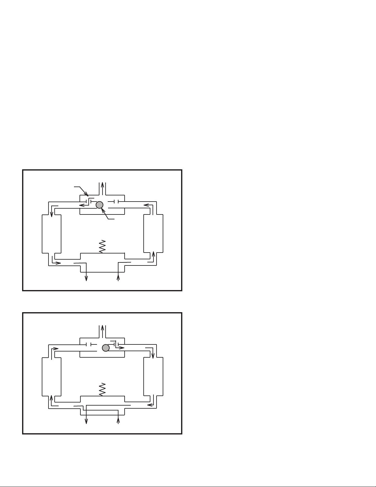
ing and resumes when the compressor restarts. The cycle
is controlled by a solid state timer with a memory feature
which is active whenever the power is on.
The timer memory insures that the dryer cycle will resume
at exactly the point at which it was interrupted by the Start/
Stop Pressure Switch. This feature provides for a balanced
work load in the drying towers, regardless of the frequency
or duration of compressor operation.
PHASE ONE: Right desiccant tower is in dehydration
mode and left desiccant tower is in purge mode. Duration is
30 seconds for this phase.
The Dryer Control Solenoid Va lve is energized by the
timer, venting the left tower to atmosphere via the exhaust
port. Compressed air is directed to the right tower to be
dried. The ball check valve prevents higher pressure air
OUTPUT
C
in the right tower from flowing to the left tower. A small
portion of dry air from the right tower passes through a
purge control orifice and to the left tower, where it expands
at lower pressure. The expanded air picks up the moisture
deposited in the tower in the previous cycle and carries it
to atmosphere via the exhaust port of the Dryer Control
Solenoid Valve.
PHASE TWO: Left desiccant tower is in dehydration
mode and right desiccant tower is in purge mode. Duration
is 30 seconds for this phase.
The Dryer Control Solenoid Va lve is de-energized by the
timer, venting the right tower to atmosphere via the exhaust port. Compressed air is directed to the left tower to
be dried. The ball check valve prevents higher pressure air
in the left tower from flowing to the right tower. A small
portion of dry air from the left tower passes through a purge
control orifice to the right tower, where it expands at lower
pressure. The expanded air picks up the moisture deposited
in the tower in the previous cycle and carries it to atmosphere via the exhaust port of the Dryer Control Solenoid
Va l ve.
E
B A
D
CYL B
EXH IN
PHASE 1
OUTPUT
B A
D
CYL B
EXH IN
CYL A
CYL A
At the completion of phase two the cycle timer proceeds to
phase one, and so forth.
2.3 Alarms
2.3.1 Humidity Alarm
On the “A” model only a color change humidity indicator
is provided for visual indication of dry air. When indicator
is pink in color the outlet air is above 10% RH. When the
indicator is blue in color the outlet air is below 10% RH.
On the “B”, ”C” and “D” models a solid state humidistat
is provided that will alarm at 2% RH. The humidistat has a
test switch and two LEDs on the dryer option panel, which
provide a means of alarm verification. A glowing red LED
indicates a high humidity alarm. The amber LED indicates
an open circuit alarm. The humidity alarm function can be
tested by moving the test toggle lever, whether in test alarm
or test clear. A humidity alarm causes the alarm light to
glow and provides a dry contact short at the alarm terminal
board at the rear of the enclosure. On “C” and “D” models
a Wet Air Bypass Solenoid Va l ve will exhaust to the atmosphere when the humistat is in alarm.
2.3.2 Outlet Pressure Alarms
PHASE 2
Figure 2
Dry-Pak Dryer Cycle
On all models, an adjustable low outlet pressure alarm
switch, preset to close at 3.0 psig on decreasing pressure is
located on the dryer option panel. The alarm provides a dry
2
Page 8

contact short at the alarm terminal board at the rear of the
enclosure. Note: on “D” models preset at 0.2 psig. On “C”
and “D” models an adjustable high output pressure alarm
switch, preset to open at 11.0 psig on increasing pressure is
located on the dryer option panel. The alarm provides a dry
contact short at the alarm terminal board at the rear of the
enclosure. Note: on “D” models preset at 1.5 psig.
4.3 Provide a 3/8” o.d. tube from the user system, but
do not connect to the dehydrator Dry Air Outlet until performing step 5.5 below.
4.4 Be sure the front panel power switch is off and
connect the dehydrator power cord to an electrical outlet
which complies with the equipment nomenclature plate.
2.3.3 Excess Run Alarm
On “C” and “D” models a fixed ten minute timer will
provide an alarm if the unit runs for more then ten minutes
without the compressor being allowed to stop. The alarm
provides a dry contact short at the alarm terminal board at
the rear of the enclosure.
2.3.4 Power Failure Alarm
All models provide a power failure alarm at the terminal
board on the rear of the enclosure.
3.0 SITE REQUIREMENTS
3.1 The Models 600 and 850 require a firm, level surface with a minimum of 3” clearance at the rear and top for
ventilation. Provide space on the sides as well if possible,
so that the cover may be easily removed for yearly compressor servicing, without relocating the unit.
3.2 The site must not be subject to freezing or extremely high temperatures. The allowable temperature range for
operation is 33°F to 100°F. A reasonably clean location
with a temperature range of 60 to 90° F will enhance the
service life of the air dryer.
4.5 If the equipment is used in a manner not specified
by the manufacturer, the protection provided by this equipment may be impaired.
5.0 START-U P OF THE MODEL 600 and 850
WARNING!
RISK OF ELECTROCUTION - All machinery must be
fitted with a means to isolate it from electrical energy
sources. The isolator must be capable of being locked
where an operator is unable, from any of the points to
which he/she has access, to check that the energy is still
cut off!
5.1 Remove the front cover of the dehydrator. Turn on
the On/Off Power switch on the front panel. After the compressor has run for a minute, check the system back pressure regulator setting to assure that the system is operating
at 45 psig on the back pressure gauge. The regulator has a
locking adjusting knob. Pull the knob out carefully a 1/4
inch to unlock.
5.2 Turn the Outlet Pressure Regulator knob counterclockwise so that no air flows from the Dry Air Outlet. The
regulator has a locking adjusting knob. Pull the knob out
carefully a 1/4 inch to unlock.
3.3 Be sure to connect the power cord only to an
electrical outlet which complies with the electrical specifications of the dryer. The grounding of this equipment is
important and this product is not to be operated with
the ground bypassed. The power cord must be placed not
in an inaccessible manner, so that the power cord can be
used as a disconnect device. Check the nomenclature plate
on the front panel for the electrical characteristics. Units
powered by 230 VA C ,60/50 HZ. will require the addition of
an electrical plug purchased locally.
4.0 INSTALLATION
4.1 Mount the Model 600 or 860 per section 3.
4.2 Provide remove alarm wires for later connection to
the alarm terminal board on the rear of the enclosure. The
alarm circuit device must have its own power source (normally 24 or 48 volts DC).
5.3 Observe the Tan k Pressure Gauge on the front panel of the dehydrator. The compressor should stop when 45
psig is reached. Turn the Outlet Pressure Regulator clockwise until air flows from the Dry Air Outlet. The compressor should start to operate when the Tan k Pressure Gauge
reaches 20 psig. If the limits are more than 2 psig outside of
those specified, adjustment to the start/stop pressure switch
will be required. Refer to section 6.4
5.4 The air dryer may exhibit a higher than normal
moisture content when it is started after a period of inactivity. If high moisture content is evident, do not connect the
Dry Air Outlet fitting to the user system until corrective
action is taken as follows:
5.4.1 Models 600A and 850A only: An outlet air moisture indicator changes color to signify higher than normal
outlet air relative humidity. This indicator will be light pink
when moist, blue when dry. If the indicator is not blue,
adjust the Outlet Pressure Regulator so that outlet air flows
through the indicator and out the Dry Air Outlet fitting.
3
Page 9

Unlock the regulator and turn the knob clockwise to cause
maximum air flow through the outlet fitting to atmosphere.
Operation of several hours may be necessary in severe
cases, to restore the indicator to a blue color.
5.4.2 Models 600B and 850B only: This unit is equipped
with a solid state humistat. On the humistat, a red LED
indicates a humidity alarm when lit. If the outlet air relative humidity is above 2% the humistat will be in alarm. If
the humistat is showing a humidity alarm, adjust the Outlet
Pressure Regulator so that air is flowing out the Dry Air
Outlet fitting. Operation for an hour or more may be necessary in severe cases, to clear the humidity alarm.
5.4.3 Models 600C/D and 850C/D only: These units are
equipped with a solid state humistat. On the humistat, a red
LED indicates a humidity alarm when lit. A wet air bypass
solenoid valve operates automatically with the humistat
when in a humidity alarm. This prevents any moist air from
entering the storage tank. The tank pressure will increase
only after the humidity alarm has automatically cleared.
Operation for an hour or more may be necessary in severe
cases, to clear the humidity alarm.
5.4.4 All Models: If high humidity is indicated, but the
dryer is operational, the condition will clear itself after an
extended period of operation. Ignore any alarms which are
present at start up.
5.5 Connect a 3/8” plastic tube from the Dry Air Outlet
fitting on the rear of the enclosure to the user system. If
more then one system is to be supplied, the use of check
valves is recommended.
5.6 Alarm connection for Models A and B only: These
units are equipped with a three place terminal board on the
rear of the enclosure for remote alarm connection. Dry contact terminals with a five amp rating will send out a summary alarm in either “CLOSED IN ALARM” OR “OPEN
IN ALARM”. Connect one alarm wire to the board labeled
“COMMON” and select the manner of receiving the summary alarm either “CLOSE IN ALARM” or “OPEN IN
ALARM” and connect the other wire to the terminal board.
5.7 Alarm Connections for Models C and D only:
These units are equipped with a Segregated Alarm terminal board (located on the rear of the enclosure) for remote
alarm connection. Dry contact terminals having a five amp
rating are provided. The alarm terminals related to each
alarm function are labeled “COMMON”, “CLOSED IN
ALARM” and “OPEN IN ALARM”. There are four alarm
output wiring options available. Selection of an alarm output characteristic is made by positioning the jump wires on
the segregated alarm terminal board in one of the following
options.
5.7.1 Alarm output option 1 :
A summary closed in alarm remote warning that one or
more of the alarm circuits is active. To utilize this option
leave the terminal board configured as received from the
factory. Yel low jump wires connect “common” terminals in
series, blue jump wires connect “closed in alarm” terminals
in series. Connect your remote alarm pair to terminals #1
and #15.
5.7.2 Alarm output option 2 :
Segregated alarms using a single common provide discrete
indication of each alarm circuit, either closed in alarm or
open in alarm, but all at one potential. To utilize this option remove the blue jump wires from the terminal board,
leave the yellow jump wires that connect the commons in
series in place. Connect your remote alarm common wire
to terminal #1 and your remaining remote wires to selected
“CLOSED IN ALARM” or “OPEN IN ALARM” terminals
as you prefer.
5.7.3 Alarm output option 3 :
A summary open in alarm remote warning that one or more
of the circuits are active. To utilize this option move only
one end of each yellow jump wire from its location in a
“common” terminal to the adjacent “open in alarm” terminal as follows: yellow jump wire #1 to #4 becomes #2 to
#4 and move the remaining yellow jump wires to connect
#5 to #7, #8 to #10 and #11 to #13. Remove the blue jump
wires from the terminal board. Connect your remote alarm
pair to terminals #1 and #14.
5.7.4 Alarm output option 4:
A completely segregated alarm output wherein a separate
voltage or frequency may be used for any or each alarm
function. Remove both the yellow and blue jump wires
from the alarm terminal board. Connect your remote alarm
wires to each function terminal set to obtain “OPEN IN
ALARM” output as you prefer.
5.8 Make final verification of the outlet pressure
regulator adjustment and verify that the adjustment knob is
locked. This completes the start up procedure.
6.0 ADJUSTMENTS
6.1 Outlet Pressure Regulator Adjustment
6.1.1 The Outlet Pressure Regulator on the front panel
of models A, B and C has a locking adjuster knob. Carefully pull out the knob a 1/4 inch to unlock. Adjust the
regulator to the desired pressure, as shown on the Outlet
Pressure Gauge. Lock the regulator knob when adjustment
is complete. On “D” models the outlet pressure regulator
has a locking nut, after all outlet pressure adjustments are
made just tighten the nut with a 7/16 inch wrench.
4
Page 10

6.2 Back Pressure Regulator Adjustment
6.2.1 The Back Pressure Regulator which is located after
the dryer assembly has a locking adjuster knob. Carefully
pull out the knob a 1/4 inch to unlock. Adjust the regulator
to the desired operating pressure using the back pressure
gauge . Recommended back pressure for these dryer is 45
PSIG. Lock the regulator knob when adjustment is complete.
6.3 Outlet Pressure Alarm Switch Adjustment
6.3.1 Adjustment of the Outlet Pressure Alarm
Switch on all models is accomplished by removing the
front cover. Located on the dryer option panel that is
mounted on the tank, use a 1/8” flat blade screw driver to
turn the slotted plastic adjuster. Screw gently clockwise to
increase or counterclockwise to decrease the adjuster of the
low output pressure or high output pressure alarm switches.
Ve r ify the adjustment by decreasing and increasing the
outlet air pressure to activate and to deactivate the alarms.
6.4 Start / Stop Pressure Switch Adjustment
WARNING!
RISK OF ELECTROCUTION - Before performing this
procedure: Disconnect from the electrical power source.
Turn the dehydrator off and disconnect from the external
power source before performing the following procedures.
6.4.1 Before adjusting the start/stop pressure switch, observe the pressure shown on the Tan k Pressure Gauge when
the compressor starts and when it stops. Make note of the
amount of change required in psig to obtain the desired setting. The compressor should start at 20 psig and stop at 45
psig +/-2 psig.
6.4.2 The Start/Stop Pressure Switch can be accessed by
first removing the screws which retain the front cover and
the top cover.
6.4.3 Mounted on the storage tank in the center of the
unit. Remove the gray plastic pressure switch cover using a
5/16” wrench. Note the two adjuster nuts of the Start/Stop
Pressure Switch. The center adjuster controls the entire
range of the pressure switch. The side adjuster controls
only the stop pressure. TURN ONLY THE CENTER ADJUSTER.
6.4.4 Each full revolution of the adjuster nut changes the
range by 2 psig. Clockwise raises, counterclockwise lowers
the amount of differential or range. Use a 3/8” open end
wrench to reach the new stop pressure (the start pressure
changes also).
6.4.5 Connect the power cord to the electric outlet and
restart the dehydrator. Again check the Stop Pressure to
verify the Start/Stop Pressure Switch adjustment. If the
desired change is complete, turnoff the dehydrator, disconnect from the electrical power source, reinstall the pressure
switch cover. Install the top cover and front cover to the
dehydrator. Finally Reconnect the power and turn on the
panel power switch.
7.0 MAINTENANCE
7.1 At 6 month intervals verify that the dryer purges
every 30 seconds when the compressor is running.
7.1.1 Verify that the adjustment of the Start/Stop Pressure Switch is correct. The compressor should start when
tank pressure declines to 20 +/-2 psig and should stop at 45
+/-2 psig. If outside of this range, refer to section 6: ADJUSTMENTS.
7.1.2 Ve r ify the Outlet Pressure alarm switches by raising and then lowering the Outlet Pressure Regulator. Return
the regulator to the normal outlet pressure setting. If pressure settings need adjustment refer to section 6: ADJUSTMENT.
7.1.3 While operating at normal outlet pressure, verify
that the compressor does not run more than 70% of the
time. If operating time exceeds this limit check the inlet
filter element of the compressor to see if it is very dirty.
Replace the filter element if indicated. If excess operation
continues, check for leaks throughout the air system.
IF THE COMPRESSOR CONTINUES TO RUN MORE
THAN 70% OF THE TIME, PERFORM THIS TEST:
Turn the power switch off and let the tank pressure reach
0 psig as indicated by the Tan k Pressure Gauge. Turn the
outlet air regulator knob fully counterclockwise to prevent
outlet air flow. Turn the power switch on and measure the
time required to reach 15 psig tank pressure. A capable
compressor, absent any air leaks, should accomplish this in
two minutes or less when operating on 60 HZ current. With
50 HZ current the maximum time would be about three
minutes. If the unit takes longer than this, a compressor
overhaul may be required. Refer to section 8.0
7.2 After each twelve months of operation, again
perform maintenance outlined in section 7.1. Install a
compressor maintenance kit (refer to compressor exploded
view fig 8) and to section 8.0 COMPRESSOR MAINTENANCE.
7.3 It is recommended that the Purge Valve be serviced
after 12 months of operation and performed at the same
5
Page 11

time as the Compressor Maintenance. Reference Purge
Va l ve Repair Kit P/N 46037.(fig 10) See manufacture’s
instructions provided with repair kit.
7.4 After 24 months, it is recommended that the Humidty
Sensor , Plug and Gasket be changed out. (Model Ve rsions
B, C, and D) . With the unit shut off , using the Test Valve,
Relieve the pressure from the Humidity Manifold until the
gauge show zero. Disconnect the Electrical Connector and
remove the Nut. Pull out the Humidly plug with the Sensor
attached. Replace with new Sensor Plug and Gasket and
secure with Nut finger tight and reattached connector. (see
fig 7)
7.5 After 24 months , it is recommended to replace the
Humidity Bypass Solenoid Va lve. ( Model Ve rsions C and
D only) With the Unit Shut off and Power Cord Disconnected, remove the 3 Electrical Connections ( note where
the Green Wire ground is connected ) . Remove the two
tubes by pressing in on the Collar and pulling the ¼ inch
tubing straight out of the fitting. Remove the two ¼-20
Phillip Head screws holding the mounting plate to the Tan k
Bracket. Pull the panel away from the tank and remove the
two M5 Phillip head screw holding the Bypass Va lve. Note
the positioning of the #1 and #2 Ports. Remove the fittings
and reinstall in the new Va lve. Reattached the Val ve to
the plate with #2 Port on the left side then reassembly in
reverse order.
8.0 COMPRESSOR MAINTENANCE.
(see manufacture’s instructions provided with service kit)
NOTE
Do not lubricate the compressor. Do not allow petroleum
products, caustics or solvents to contact any part of the
compressor. Parts may be cleaned with soap and water
followed by wiping down with a dampened cloth.
WARNING!
RISK OF ELECTROCUTION - Before performing this
procedure: Disconnect from electrical power source.
WARNING!
RISK OF BURNS - Normal compressor operation will
cause head temperature to exceed 212 °F (100 °C). Be
careful when handling a hot compressor.
8.1 When replacing the compressor air filter, first remove the outer cap from the filter housing, discard the old
filter and clean the housing with a rag. Install the new filter
and replace the cap.
8.2 DISASSEMBLY: It is not necessary to remove
the filter from the cylinder head as metal chips could be
dislodged and enter the unit. Remove the shroud, cylinder
head, and valve components. Do not rearrange the valve
components. Remove the cylinder and rings. Make sure
all parts are clean before reassembling. DO NOT use any
chlorinated solvents to clean valves, or any liquids to
flush units. THE STAINLESS STEEL VALVE S MAY BE
CLEANED WITH WAT E R. All parts, except the valves,
can be cleaned with any industrial, nonflammable, nontoxic, cleaning solvent.
8.3 ASSEMBLY: Install piston seals, piston rings, and
rider rings on the piston. Locate ring joints approximately
opposite each other. Attach cylinder to bracket with the
cylinder screws and lock washers. Tighten screws finger
tight. Move pistons to top dead center position. Adjust
cylinder flush with top of piston and torque cylinder screws
to 150-160 in. lbs. Tor que second time. Stack the valve
components in order as shown in figure 8. Install the cylinder head, lock washers, and head screws. The exhaust ports
in the cylinder head have been marked by omitting the ends
of two fins. Tor que head screws to 150-160 in.-lbs. Tor que
head screws again after running for 10 minutes.
9.0 TROUBLE SHOOTING
9.1 Outlet Air Pressure Alarm
Be sure the Outlet Pressure Gauge indicates the desired
pressure. If the gauge reliability is in question, it can be
verified by connecting a test gauge to the test valve labeled
line pressure, on the control panel. Replace the gauge if
indicated. The line pressure alarm switches are labeled.
For outlet pressure alarm switch adjustment refer to section 6.3.
9.2 Humidity Alarm
A list of conditions which can cause a high humidity alarm
(a Humidity Alarm on models with suffix B, C and D) and
the order in which to proceed follows:
a: Faulty alarm circuit (9.2.1)
b: Dryer not cycling (9.2.2)
c: Plugged purge outlet (9.2.3)
d: Low Back Pressure (9.2.4)
e: Infrequent operation (9.2.5)
f: High temperature (9.2.6)
g: Desiccant towers (9.2.7)
h: Needs time to clear (9.2.8)
NOTE: Model 600A and 850A are equipped with a color
change moisture indicator. If excessive outlet air moisture
is indicated (pink in color ) proceed to section 9.2.2.
9.2.1 Humidistat Operational Tes t
9.2.1.1 Excessive moisture will cause the Alarm Light on
the control panel to glow. Determine which LED on the
6
Page 12

humidistat is lit, amber or red.
9.2.8 Dry-Down After Repair
9.2.1.2 If the humidity alarm is active and the amber
LED is lit, VERIFY THE ALARM by moving the test
toggle to “Test Clear”. If this action clears the alarm
temporarily, the humidistat is working properly and there
is an open condition in the sensor circuit. Check for a
loose connection between the humidistat and sensor. If
connections are ok, the sensor itself has an open circuit
and must be replaced. If the test toggle will not temporarily clear the amber LED when it is lit, replace the
humidistat.
9.2.1.3 If the humidity alarm is active and the red LED
is lit: VERIFY THE ALARM by moving the test toggle
to “Test Clear”. If this action clears the alarm temporarily, the humidistat is working properly. Perform the
corrective action indicated in the following paragraphs.
If all operational checks reveal no reason for the alarm
condition, but the alarm persists, replace the sensing element.
9.2.2 If the dryer does not cycle (does not purge audibly each 30 seconds of compressor operation), replace
the dryer solenoid valve. If the condition persists, replace
the cycle timer.
9.2.3 A restricted exhaust port on the dryer solenoid
valve can cause excessive pressure in the desiccant towers while purging. This can cause a humidity condition.
Be sure that the exhaust port is not plugged.
9.2.4 If the system back pressure setting falls below
43 psig. re-adjust the back pressure setting to the correct
setting of 45 psig +/-2 psig.
9.2.5 If the user system requires so little air that the
compressor operates less frequently than once each 45
minutes, it is recommended that an external fixed air
leak is added to the unit. This leak will allow the unit to
operate more frequently.
9.2.6 Be sure that the dehydrator is not located where
the temperature rises above 100° F.
9.2.7 The desiccant used in the drying towers is
molecular sieve, which has a normal useful life equal
to the dehydrator. Reduced service life can occur due
to air borne contaminants (hydrocarbons, acids etc.)
which may plug or degrade the desiccant. This is seldom
the cause of a high humidity condition, but if all other
possible causes for a high humidity condition have been
ruled out, and especially after years of service, replacement of the desiccant towers is indicated.
If a malfunction of the timer, dryer solenoid valve or a low
back pressure setting caused a humidity condition, the unit
must operate after repairs are completed for about an hour
in order to dry the desiccant towers and clear the humidity
alarm. If (not applicable to models with suffix A) a defective sensor element was the cause of alarm, it will normally
clear after 15 minutes of operation or less with a new sensor in place.
9.3 Excess Run Alarm
Check the duration of time the compressor starts to when
it stops. This time should be less than seven (7) minutes
without any short-term humidity problem. If the duration
of time is higher than seven minutes check for any air leaks
within the unit and outlet fitting. Check the user system for
higher than normal flow requirements. If the unit has no air
leaks or high flow requirements and the excess run alarm
clears after restarting the unit, a compressor overhaul kit
should be installed. If the excess run alarm does not cause
an alarm after eleven minutes of compressor run time replace the excess run timer. If the excess run alarm does not
clear or is in alarm after less than ten minutes of run time,
replace the excess run timer. The excess run timer should
be 10 minutes +/- 2 minutes.
10.0 Service Information
Should you need to contact us please call our Customer
service department on (207) 655-8525 or Tol l Free at (877)
247-3797
When returning a unit for factory service, Call the customer service department for a service return authorization
number (SRA). The device should be boxed securely and
contain contact information, contact telephone number, billing information, and return shipping information. If device
is being sent to the factory for service, a written statement
of the problem of symptoms should be included. The SRA
number must be on the outside of the package or indicated
on the shipping label.
NOTE: Do not ship equipment contaminated with any type
of hazardous/harmful substance.
SPX Dielectric
28 Tower Road, Raymond Maine. 04071
Phone (207) 655-8525 Toll Free: (877) 247-3797 Fax:
(207) 655-8535
Email: rd.sales.us@spx.com
7
Page 13

15
TP
14
TP
13
12
1
2
3
10
7
11
4
9
8
5
6
COMPONENT LIST
1. Intake Filter 8. Color Change Humidity Indicator
2. Compressor 9. Air Storage Tank
3. Heat Exchanger 10. Stop / Start Pressure Switch
4. Purge Solenoid Val ve 11. Tank Pressure Gauge
5. Dryer Assembly 12. Outlet Pressure Regulator
6. Back Pressure Regulator 13. Outlet Pressure Gauge
7. Back Pressure Gauge 14. Low Outlet Pressure Alarm
15. Outlet Air Fitting
Figure 2
Flow Schematic for Model “A” Dryers
8
Page 14

16
TP
15
TP
14
13
1
2
3
11
9
5
10
8
7
6
12
4
COMPONENT LIST
1. Intake Filter
2. Compressor 10. Air Storage Tank
3. Heat Exchanger 11. Stop / Start Pressure Switch
4. Purge Solenoid Val ve 12. Tank Pressure Gauge
5. Dryer Assembly 13. Outlet Pressure Regulator
6. Humidity Sensor Manifold 14. Outlet Pressure Gauge
7. Humidity Sensing Element 15. Low Outlet Pressure Alarm
8. Back Pressure Regulator 16. Outlet Air Fitting
9. Back Pressure Gauge
Figure 3
Flow Schematic for Model “B” Dryers
9
Page 15

16
18
TP
17
TP
15
14
1
2
3
13
4
12
9
11
10
5
8
7
6
COMPONENT LIST
1. Intake Filter 10. Humidity Bypass Valve
2. Compressor 11. Air Storage Tank
3. Heat Exchanger 12. Stop / Start Pressure Switch
4. Purge Solenoid Val ve 13. Tank Pressure Gauge
5. Dryer Assembly 14. Outlet Pressure Regulator
6. Humidity Sensor Manifold 15. Outlet Pressure Gauge
7. Humidity Sensing Element 16. High Output Pressure Alarm
8. Back Pressure Regulator 17. Low Outlet Pressure Alarm
9. Back Pressure Gauge 18. Outlet Air Fitting
Figure 4
Flow Schematic for Model “C & “D”” Dryers
10
Page 16

21,22
9
7
6
6
8
3
4
16
13
5
Figure 5
Front View
17
27
15
31
32
30
Figure 6
Front View (Cover removed)
11
Page 17

33
34
35
36
9
10
11
19
23
2
18
1
28
27
20
12
Figure 7
Side View (Cover removed)
26
24, 25
Figure 8
Back View
12
Strip insulation off wire
Insert tip of screwdriver blade
Push down and insert wire the release
Page 18

TABLE IV
LIST OF COMMON SPARE PARTS
ITEM NO. DESCRIPTION QTY. PART NO.
1. Spare 600 Compressor 115Vac 1 48163
Spare 600 Compressor 230Vac 1 48164
Spare 850 Compressor 115Vac 1 48165
Spare 850 Compressor 230Vac 1 48166
1a. Compressor Service Kit for 600 and 850 models 0046789501
2. Storage tank 1 39530
3. Line Pressure Gauge (A, B and C) 1 0017221016
Line Pressure Gauge (D only) 1 41776
4. Tank Pressure Gauge 1 0017221018
5. Circuit Breaker 115Vac 1 13281
Circuit Breaker 230Vac 1 30172
6. Power On Light 115Vac 1 13226
Power On Light 230Vac 1 41136
7. Alarms Light 115Vac 1-3 13225
Alarms Light 230Vac 1-3 41135
8. Line Regulator (A,B and C) 1 40328
Line Regulator (D only) 1 10814
9. Test Valves 3 0017495001
10. Back Pressure Regulator 1 0020523003
11. Back Pressure Gauge 1 0017221028
12. Cabinet feet 4 39959
13. Relay 115Vac 1-3 14126
Relay 230Vac 1-3 14127
14. Compressor contactor 115Vac 1 47052
Compressor contactor 230Vac 1 47053
15. Outlet Alarm Pressure Switch (on A, B and C ) 46752
Outlet Alarm Pressure Switch (on D only) 46753
15A Barb Fitting (part of switch) 1 36696
15B Gasket (part of switch) 1 40679
16. Solid State Timer 115Vac 1 48540
Solid State Timer 230Vac 1 48541
17. Start/Stop Pressure Switch 1 0060353003
18. Spare (complete) Dryer Solenoid Va l ve 115Vac 1 48178
Spare (complete) Dryer Solenoid Va l ve 230Vac 1 48179
18A Spare Dryer Solenoid Coil 115Vac 1 0019525001
Spare Dryer Solenoid Coil 230Vac 1 0019525002
18B Repair Kit Solenoid Val ve 1 46037
19. Spare Complete 600 Dryer 1 48169
Spare Complete 850 Dryer 1 48170
20. Spare Power Cord 115Vac 1 48172
Spare Power Cord 230Vac 1 67452
21. Fuse Holder 2/3 48061
22. Fuse .8 amp for 115Vac 52528
Fuse 1/2 amp for 230Vac 43803
23. Spare Heat Exchanger Assy. 1 48174
24. Alarm Terminal Block 0060192006
25. Alarm Terminal end 0060192005
26. Outlet Fitting 1 0016853013
27. Ventilation Fan 115Vac 1 39957
Ventilation Fan 230Vac 1 35066
28. Shock Mounts 4 44390
13
Page 19
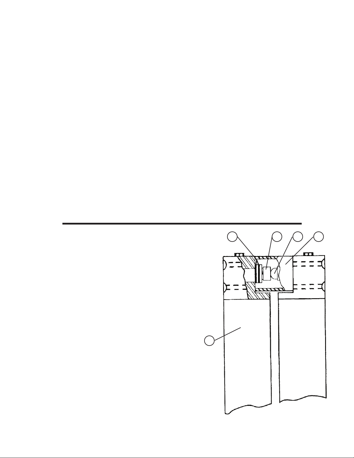
TABLE V
LIST OF PARTS ON ALL MODELS
LIST OF PARTS ON MODEL A
ITEM NO. DESCRIPTION QTY. PART NO.
29. Humidity Indicator 1 39962
LIST OF PARTS ON MODELS C AND D
ITEM NO. DESCRIPTION QTY. PART NO.
30. Excess Run Timer 115Vac 1 17107
Excess Run Timer 230Vac 1 33384
31. 3 Way Bypass Solenoid Va l ve 115Vac 1 39984
3 Way Bypass Solenoid Va l ve 230Vac 1 34724
LIST OF PARTS ON MODELS B, C AND D
ITEM NO. DESCRIPTION QTY. PART NO.
32. Humidistat 1 14701
33. Humidity Sensor Element 1 15688
34. Humidity Sensor Shield 1 30986
35. Gasket 1 89795
PARTS LIST FOR DESICCANT DRYER
ITEM PART NO. DESCRIPTION
REF. 48169 DESICCANT DRYER ASSY, MODEL 600
REF. 48170 DESICCANT DRYER ASSY, MODEL 850
1. 47728 MODEL 600 & 850 DESICCANT CHAMBER
2. 47725 CENTER MANIFOLD BLOCK
3. 41548 BALL SEAT MODEL 600
3a 104292 BALL SEAT MODEL 850
4. 0015903005 BALL CHECK
5. 0014000017 O-RING SEAL
5 3 4
1
2
14
Figure 9
Desiccant Dryer Assembly
Page 20

Figure 10
Solenoid Valve- Exploded View
List of Compressor Parts
Ref. No. Description Qty
1 Filter Muffler Element 1
2* FilterFelt 1
3 Safety Val ve 1
4 Cylinder Feed 1
5* Head Gasket 1
6* Valve, Outlet 1
7 Valve Plate 1
8* Valve, Inlet 1
9* Cylinder Gasket 1
10 Cylinder 1
11* Piston Ring 2
12* Piston Seal 2
13* Rider Ring 1
Figure 11
Compressor - Exploded View
14 Piston Rod Assy 1
15 Counter Weights 1
16 Flat Key 1
17 Fan 1
18 Shroud 1
Dots(*) indicate items contained in Service kit
Use service kit P/N 46789-501 for Models 600 & 850
15
Page 21

Figure 12
“A” Series, 115V Wiring Schematic
16
Page 22

Figure 13
“A” Series, 230V Wiring Schematic
17
Page 23

Figure 14
“B” Series, 115V Wiring Schematic
18
Page 24

Figure 15
“B” Series, 230V Wiring Schematic
19
Page 25

Figure 16
“C” & “D” Series, 115V Wiring Schematic
20
Page 26
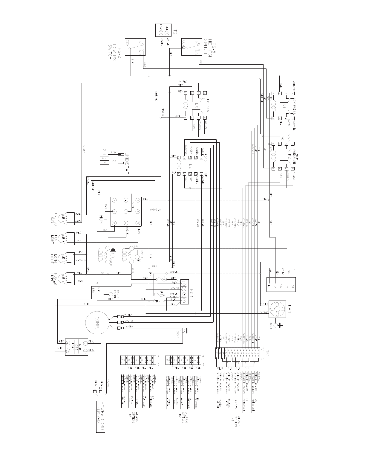
Figure 17
“C” & “D” Series, 230V Wiring Schematic
21
Page 27

TABLE VI
GLOSSARY OF TERMS
Altitude: The distance which the installation is above sea level expressed in feet/meters, used interchangeably with elevation.
Ambient: The environment surrounding the dehydrator. Ambient factors which can influence a dehydrator include the
temperature, the relative humidity, the atmospheric pressure and quantity of various pollutants which are present.
Desiccant: The component within the dryer towers which is used alternately to retain, then to expel moisture from the
process air. SPX Radiodetection dryers employ desiccant which is totally inert, that is; it undergoes no chemical or physical change in normal use.
Dew Point: Expressed in °F., the temperature at which dew or frost would form at 14.7 PSIA. The dew point of a given
air sample rises with increased pressure. In 1943 SPX Dielectric established a dew point of -400F. as standard for their
compressor / dehydrators and for the pressurization of the communications equipment which is produced at SPX Radiodetection. NOTE: -400 is the one point at which the Fahrenheit and Celsius scales are numerically equal.
Dry-Pak: A patented dryer design and registered trade mark of SPX Radiodetection which describes the most simple and
efficient heatless air dryer. A Dry-Pak consists of two desiccant towers, two maintenance free ball checks and two direct
acting solenoid valves controlled by a solid state timer. The main air flow is handled by the ball checks without measurable pressure loss. Only the purge air flows through the two way solenoid valves, providing high efficiency and long
trouble free service.
Elevation: The distance which the installation is above sea level expressed in feet/meters, used interchangeably with
altitude.
Line Pressure: The pressure of the low pressure outlet system, which is controlled by the adjustment of the Line Pressure Regulator, is displayed on the Line Pressure Gauge, and is monitored by the adjustable Low and High Pressure Alarm
Switches.
PSIA/kPaa: Pounds per Square Inch Absolute / kilo pascal Absolute. The measure of the pressure of a gas or liquid,
expressed in pounds per square inch, relative to a total vacuum. Standard atmosphere at sea level equals 14.7 PSIA (approx.). / 101 kPaa (approx)
PSIG/kPa: Pounds per Square Inch Gauge. The measure of the pressure of a gas or liquid within a component or system,
to the degree it is greater than that of the surrounding atmosphere, expressed in pounds per square inch. The internal pressure as shown on the gauges used on air dryers.
SCFD/SCMD: Standard Cubic Feet per Day. A rate of air flow measured in cubic feet at 14.7 PSIA and 680 F. One
SCFD when subjected to 10 PSIG (without temperature change) would occupy a space equivalent to 0.6 cubic feet.
Segregated Alarm: An alarm circuit which provides separate terminations for each alarm function within the dehydrator.
Segregated alarms can provide to a remote location the information necessary for establishment of maintenance priorities.
Alarm terminations which either close in alarm or open in alarm, or dual function terminations may be available, dependent on design parameters.
Std. conditions: Standard operating conditions imply a reasonably clean environment at 70°F.(21°C.) and sea level. Ambient conditions impact dryer maintenance needs.
Summary Alarm: An alarm which does not identify an individual condition, but which can indicate an active state of one
or more alarm sensors within the dehydrator. Alarm terminations which either close in alarm or open in alarm, or dual
function terminations may be available, dependent on design parameters.
System Pressure: The pressure at which the compressors and the drying towers (desiccant towers) operate. System
Pressure determines the quantity of compressed air flow, the quantity of purge air and the moisture load on the desiccant
towers.
22
Page 28

WARRANTY
The Manufacturer warrants that all goods supplied hereunder, whether or not of its own manufacture, will be of the kind described
herein or in any specication and drawing approved by the Manufacturer and free from defects in material or workmanship
under normal use and prescribed maintenance for a period of one (1) year, with the exception of air dryers utilizing water sealed
compressors as well as the compressors themselves which shall be for two (2) years. Neither this warranty nor any other, expressed
or implied, shall apply to goods delivered hereunder which have been damaged or subjected to alteration or negligence after
delivery. The Manufacturer’s only obligation for breach of this warranty shall be the repair, without charge, or the furnishing EX Works
Raymond Maine, of a similar part to replace any part which within one (1) year, with the exception as noted above, from date of
shipment is proven to have been defective, provided that (i) the Purchaser shall have notied the Manufacturer within ten (10) days
of the discovery of such defect and not later than ten (10) days after the last day of this warranty, and (ii) the Manufacturer shall have
the option of requiring the return of the defective material (transportation prepaid) to establish the claim. The Manufacturer shall not in
any event be liable for the Purchaser’s manufacturing costs, loss of prots, good will or any other special, consequential, incidental,
or other damages resulting from such defects. THERE ARE NO OTHER WARRANTIES, EXPRESSED OR IMPLIED, WHICH
EXTEND BEYOND THE WARRANTY SET FORTH HEREIN.
Radiodetection (USA) 28 Tower Road, Raymond, Maine 04071, USA
Tel: +1 (207) 655 8525 Toll Free: +1 (877) 247 3797 Fax: +1 (207) 655 8535 rd.sales.us@spx.com www.radiodetection.com
Radiodetection Ltd. (UK) Western Drive, Bristol BS14 0AF, UK
Tel: +44 (0) 117 976 7776 Fax: +44 (0) 117 976 7775 rd.sales.uk@spx.com www.radiodetection.com
© 2017 Radiodetection Ltd. All rights reserved. Radiodetection is a subsidiary of SPX Corporation. Dielectric is a trademark of Radiodetection in the United States and/or other countries.
Due to a policy of continued development, we reserve the right to alter or amend any published specification without notice. This document may not be copied, reproduced, transmitted,
modified or used, in whole or in part, without the prior written consent of Radiodetection Ltd.
 Loading...