


ME 100 V3
RS485 – MODBUS-RTU
MANUALE DI INSTALLAZIONE ED USO
INSTALLATION AND INSTRUCTIONS MANUAL
MANUAL DE INSTALACION Y USO


ITALIANO
- 3 -
CARATTERISTICHE TECNICHE
Dimensioni
• Contenitore 90x90x130 mm incluse morsettiere.
• Pannello frontale 96x96 mm.
• Peso 0.6 Kg.
Alimentazione
• Alimentazione universale (24÷240) Volt AC/DC ± 10% 50/60 Hz senza rispetto della
polarità, assorbimento 4 VA.
Ingressi
• Otto ingressi analogici, rilevamento e controllo temperatura con sensori PT100 a tre
fili nel range da -10 a +200 °C.
Uscite
• Quattro relè 250V AC 5A massimi (carico resistivo), 1 contatto pulito di scambio.
• Comunicazione seriale RS485 Full Duplex protocollo MODBUS-RTU.
Caratteristiche
• Contenitore in NORYL auto estinguente.
• Display a segmenti luminosi.
• Visualizzazione automatica della temperatura più elevata e del relativo numero di
canale.
• Segnalazioni di pre-allarme, allarme, guasto sonde, ventilazione, funzionamento
manuale, massimi storici.
• Accesso alla programmazione della centralina direttamente da pannello frontale.
• Possibilità di selezionare indipendentemente ogni singolo canale.
• Soglia di allarme e preallarme impostabile nel range (-9°C ÷ 199°C).
• Precisione: ±1% riferito al fondo scala ±1 digit.
• Gestione del ventilatore di raffreddamento su tutte le sonde.
• Controllo del ventilatore mediante isteresi con due valori di temperatura (H e L).
• Quattro modalità di funzionamento selezionabili.

ITALIANO
- 4 -
• Riconoscimento sonde in avaria, massima flessibilità di gestione e semplicità di
programmazione, controllo della validità dei dati introdotti in fase di
programmazione.
• Memorizzazione permanente dei valori programmati e dei dati raggiunti da ciascun
canale (soglie e massimi storici).
• Rigidità dielettrica tra i contatti dei relè e linea di alimentazione 2.5 KVAC per 60".
• Possibilità di utilizzare le sonde per termostatare l'ambiente.
• Risoluzione 1° C.
• Temperatura di lavoro (-40°C ÷ 60°C).
• Umidità massima ammessa: 90% senza condensa.
• Collegamento mediante morsettiere estraibili polarizzate.
• Possibilità di commutare manualmente i relè mediante il menù di test relè per
simulare o controllare l’affidabilità del contatto.
• Manuale tecnico in tre lingue (altre lingue a richiesta).
• Costruzione in accordo alle normative .
• Filtro d' ingresso contro i disturbi a normativa .
• Tropicalizzazione (opzionale).
MONTAGGIO
Eseguire nel pannello un foro da 91X91 mm, fissare la centralina con i ganci in
dotazione.
ALIMENTAZIONE
La centralina può essere alimentata con (24÷240) Volt AC/DC ±10% 50-60 Hz senza
rispetto di polarità.
I morsetti di alimentazione sono indicati con la sigla AL1-AL2 e sono inoltre riportati in
tabella TAB 1 alla fine del manuale.
COLLEGAMENTI ELETTRICI
Eseguire i collegamenti sulle morsettiere estraibili seguendo lo schema riportato in
tabella TAB 1 alla fine del manuale.

ITALIANO
- 5 -
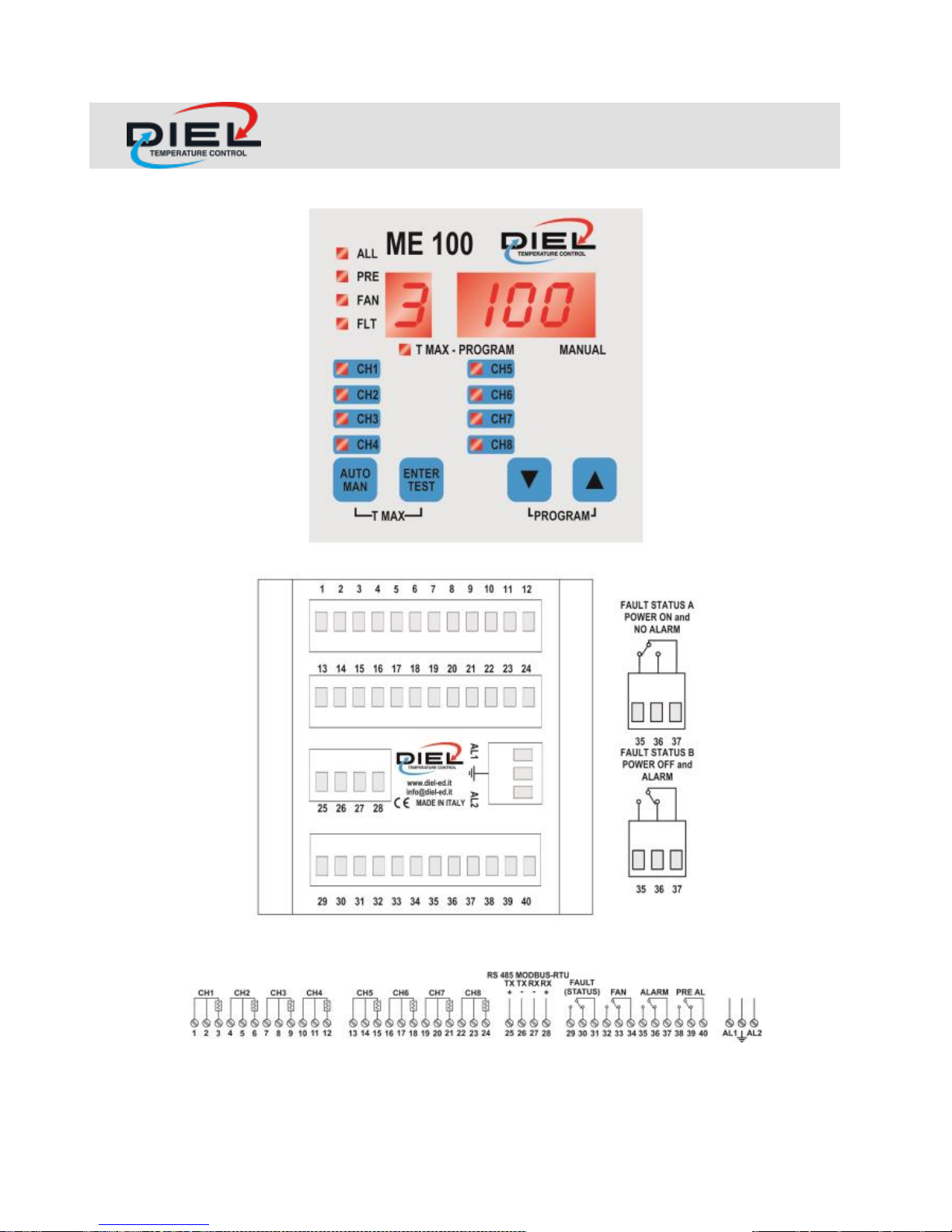
Il relè di FAULT risulta normalmente eccitato durante il funzionamento della centralina
(FAULT STATUS A, TAB 1), in caso di guasto alle sonde o di mancanza di
alimentazione il relè si diseccita (FAULT STATUS B, TAB 1).
Il relè di FAN è preposto alla gestione dei ventilatori di raffreddamento del
trasformatore oppure per il condizionamento del locale dove è
situato il trasformatore.
I relè ALARM e PRE AL vengono eccitati al superamento di un grado delle rispettive
soglie impostate.
Ogni sonda PT100 standard è dotata di tre fili, uno bianco e due rossi.
Collegare il filo bianco nei morsetti contrassegnati dal simbolo del sensore nella
serigrafia, morsetti (3,6,9,12,15,18,21,24).
I ventiquattro morsetti di ingresso relativi alle otto sonde sono così predisposti:
Sonda N. 1 morsetti 1-2-3, Sonda N. 2 morsetti 4-5-6.
Sonda N. 3 morsetti 7-8-9, Sonda N. 4 morsetti 10,11,12.
Sonda N. 5 morsetti 13-14-15, Sonda N. 6 morsetti 16-17-18.
Sonda N. 7 morsetti 19-20-21, Sonda N. 8 morsetti 22,23,24.
Porta seriale RS485 full duplex:
• Trasmissione positivo TX+: morsetto 25
• Trasmissione negativo TX- morsetto 26
• Ricezione positivo RX+ morsetto 28
• Ricezione negativo RX- morsetto 27
Tutti i cavi di trasporto dei segnali di misura dovrebbero preferibilmente essere:
• separati da quelli di potenza,
• schermati meglio se anche twistati,
• di sezione non inferiore a 0.5 mm².
DESCRIZIONE SEGNALAZIONI
Le lettere che compaiono sul display a singola cifra assumono il seguente significato:
F: modo di funzionamento, assume valori da zero fino a tre.
P: soglia di preallarme oltre la quale si eccita il relativo relè
A: soglia di allarme oltre la quale si eccita il relativo relè
L: soglia inferiore sotto la quale si diseccita il relè di ventilazione.
H: soglia superiore oltre la quale si eccita il relè di ventilazione.

ITALIANO
- 6 -
t: tempo minimo di attivazione ventilazione espresso in minuti che intercorre tra una
accensione ed il successivo eventuale spegnimento.
S: velocità di trasmissione porta seriale RS485 (vedere dettagli al capitolo
PROGRAMMAZIONE DELLA CENTRALINA)
d: ritardo risposta di comunicazione sulla porta seriale RS485 espresso in centesimi di
secondo (vedere dettagli al capitolo PROGRAMMAZIONE DELLA CENTRALINA)
U: indirizzo del dispositivo nella rete RS485.
Le scritte che compaiono sul display a tre cifre assumono il seguente significato:
ICF: sonda PT100 in avaria (interruzione oppure assenza di sonda)
SCF: sonda PT100 in avaria (corto circuito)
rES: azzeramento memoria guasto sonde avvenuto
FAn: ventilazione relativa ad uno specifico canale
CH(n): stato di uno specifico canale n (1-8)
PrE: relè di preallarme
ALL: relè di allarme
AIr: relè ventilazione
FLt: relè di guasto
PROGRAMMAZIONE DELLA CENTRALINA
Premendo a lungo e contemporaneamente i tasti UP e DOWN si entra in modalità
programmazione.
I tasti, in questa fase assumono le seguenti funzioni:
Tasto UP incrementa il valore proposto, tasto DOWN decrementa il valore proposto,
tasto ENTER conferma il valore e passa al parametro successivo.
La programmazione inizia dalla scelta del modo di funzionamento F.
F=0: gruppo di otto canali attivi, una sola soglia di allarme e preallarme valida per tutti i
canali, funzione di ventilazione disattivata. Con F=0 si impostano solo i due parametri
P ed A.
F=1: gruppo di otto canali attivi, una sola soglia di allarme e preallarme valida per tutti i
canali, funzione di ventilazione attiva con una sola soglia di accensione e spegnimento
ventilazione valida per tutti i canali.
Con F=1 si impostano solo i quattro parametri P, A, L, H.

ITALIANO
- 7 -
F=2: gruppo di otto canali attivi, una sola soglia di allarme e preallarme valida per tutti i
canali, funzione di ventilazione attiva, una sola soglia di accensione e spegnimento
ventilazione valida per tutti i canali, controllo ventilazione anche a tempo (parametro t).
Con F=2 oltre ai parametri impostati con F=1 si imposta il parametro t in minuti cioè il
tempo in minuti che deve restare comunque attiva la ventilazione prima di intervenire
sullo spegnimento. Questo garantisce un tempo minimo di attivazione ventilazione
indipendentemente dal valore impostato dalla soglia L.
F=3: programmazione indipendente per ogni canale di tutte le soglie di allarme,
preallarme, accensione e spegnimento ventilatore; Con F=3 vengono chiesti in
successione i seguenti parametri: Tempo t in minuti, cioè il tempo che deve restare
comunque attiva la ventilazione prima di intervenire sullo spegnimento. Questo
garantisce un tempo minimo di attivazione ventilazione indipendentemente dal valore
impostato dalla soglia L.
Per ogni canale appare poi la scritta CH(n) con n (1-8), tramite i tasti UP e DOWN è
necessario decidere se rendere il canale attivo oppure no, in caso affermativo, viene
chiesto di introdurre le soglie P e A.
Appare di seguito la scritta FAn, tramite i tasti UP e DOWN è necessario decidere se
si desidera controllare la ventilazione su quel canale oppure no, se affermativo, viene
inoltre chiesto di introdurre le soglie L e H di ventilazione, in caso il canale non sia
attivo o nel caso non si desideri la ventilazione, viene proposta la scelta per il canale
successivo.
Alla fine si accede alla configurazione dei parametri di comunicazione seriale RS485.
La lettera S indica la velocità di comunicazione in bit per secondo (bps) come riportato
di seguito.
S=5 2400 bps, S=6 4800 bps, S=7 9600 bps
Gli altri parametri (non modificabili) di comunicazione sono parità NONE, bit dati 8, bit
stop 1.
Oltre a questi dati è possibile impostare un tempo di ritardo d in centesimi di secondo
fra la fine della ricezione di un comando valido (dati ed indirizzo corretti) e la
successiva trasmissione da parte del dispositivo, questo per permettere al sistema di
supervisione di predisporsi per la ricezione.
Il ritardo di default è 25 centesimi di secondo.
Infine viene richiesto il parametro U che rappresenta l’indirizzo che individua
univocamente il dispositivo nella rete; il valore di default per l’indirizzo è zero, risulta

ITALIANO
- 8 -
pertanto sconsigliabile utilizzare tale indirizzo come indirizzo valido sulla rete al fine di
evitare conflitti con altri dispositivi eventualmente presenti e non ancora configurati.
Configurazione di default: F=0, P=140, A=160, L=90, H=100, t=0, d=25, S=7, U=0
Per motivi di sicurezza viene in ogni caso controllato il tempo necessario per la
programmazione. Oltre un minuto dall’inizio della fase di programmazione, la stessa
viene interrotta e non salvata (restano attivi pertanto i parametri precedentemente
presenti in memoria). Alla fine della programmazione, vengono salvati i nuovi dati in
memoria, viene effettuato un test dei display, la centralina si porta quindi in modalità di
visualizzazione automatica.
VISUALIZZAZIONE DATI
Contestualmente alla modalità di funzionamento F si possono visualizzare tutti i
parametri di interesse mediante i tasti UP e DOWN. Per visualizzare costantemente un
dato oppure la lettura di un canale, posizionarsi sullo stesso e premere il tasto AUTO/
MANUAL, il LED MANUAL si accenderà segnalando lo stato di funzionamento
manuale. Per ritornare a visualizzare il canale più caldo in automatico premere
nuovamente il tasto AUTO/MANUAL. Per accedere alla visualizzazione dei massimi
valori storici registrati premere contemporaneamente ed a lungo i tasti
AUTO/MANUAL e ENTER/TEST, il LED PROG-TMAX segnalerà l’ingresso nel relativo
menù. Sempre utilizzando i tasti UP e DOWN si potranno vedere i massimi relativi ai
canali attivi. Per ritornare alla visualizzazione normale premere AUTO/MANUAL. La
memorizzazione dei massimi viene cancellata ogni volta che si effettua una nuova
programmazione della centralina.
PROTOCOLLO MODBUS-RTU
Registri MODBUS-RTU: si rinvia alla fine del manuale.
TEST DEI RELE’
Premendo il tasto ENTER/TEST viene effettuato il test del display, tenendolo premuto
a lungo si entra nel menù di test relè. Utilizzando i tasti UP e DOWN si possono far
commutare i relè. Per passare ai successivi relè premere ENTER/TEST, per uscire dal
menù premere AUTO/MANUAL.

ITALIANO
- 9 -
DIAGNOSTICA SONDE TERMOMETRICHE
Gli stati di anomalia delle sonde sono segnalati nel seguente modo:
• commutazione del relè FLt (guasto)
• accensione del LED di FAULT,
• lampeggio del LED relativo al canale guasto e memorizzazione permanente dello
stesso.
In tali casi è possibile conoscere la natura dei guasti nel seguente modo:
• se la sonda PT100 risulta essere interrotta, viene visualizzata la scritta lampeggiante
ICF con relativo numero di canale
• se la sonda PT100 risulta essere in corto circuito, viene visualizzata la scritta
lampeggiante SCF con relativo numero di canale.
Quando una sonda attiva viene rilevata guasta il dispositivo memorizza il fenomeno
mantenendo lampeggiante il relativo LED anche se questa ultima ripristina il normale
funzionamento; per cancellare la memoria di guasto premere a lungo il tasto AUTO/
MANUAL fino al comparire della scritta rES sul display.
NORME DI GARANZIA
La centralina è coperta da garanzia per un periodo di 3 anni dalla data di collaudo
posta sia sull’etichetta che sul manuale allegato. La garanzia è ritenuta valida quando
è stato accertato che le cause del guasto sono imputabili a difetti di fabbricazione o ad
errata taratura delle sonde.
Non si risponde invece per guasti dovuti ad errato cablaggio delle sonde o errata
tensione di alimentazione (es. 400 Volt AC).
Non si risponde in ogni caso per danni provocati dal mal funzionamento della
centralina stessa.
Le riparazioni in garanzia, salvo diverso accordo tra le parti sono effettuate presso la
nostra sede di MONTECCHIO MAGGIORE (VI).
ATTENZIONE
Non effettuare prove di rigidità dielettrica o di scariche parziali sulle macchine
elettriche con la centralina inserita, evitare se possibile di collegare direttamente la

ITALIANO
- 10 -
centralina al secondario del trasformatore da proteggere, può accadere che, senza
protezione, alla chiusura dell'interruttore a valle del trasformatore, si presentino
sovratensioni che possono danneggiare l'apparecchiatura. Questo è tanto più evidente
se la tensione di alimentazione della centralina, è di 230 V AC e se esistono
condensatori di rifasamento.
CERTIFICATO DI COLLAUDO
La procedura di collaudo viene effettuata nel seguente modo:
• Funzionamento dei pulsanti.
• Prova dei contatti dei relè.
• Controllo meccanico generale.
• Calibrazione e linearizzazione a +30 ºC e +150 °C.
• Funzionamento per 48 h a tensione di alimentazione variabile.
• Prova di isolamento tra alimentazione e contatti relè a 2.5KV AC per 60”.
• Controllo trasmissione seriale RS485 full duplex.

ENGLISH
- 11 -
TECHNICAL FEATURES
Dimensions
• Box 90x90X130 mm included terminal blocks.
• Front panel 96X96 mm.
• Weight 0,6 Kg.
Power Supply
• Power supply (24÷240) Volt AC/DC ± 10% 50/60 Hz without polarity respect,
absorption 4 VA.
Inputs
• Eight analogical inputs, temperature control and mapping with PT100 sensor at
three wires inside range from -10 °C to +200 °C.
Outputs
• Four relays 250V AC, 5A max (resistive load), free switch contact
• Serial communication port RS485 full duplex protocol of MODBUS – RTU.
Characteristics
• Self-extinguishable NORYL Box.
• Display with light segments.
• Visualisation of max temperature and the relevant channel in the automatic mode.
• Alerts of pre-alarm, alarm, probes fault, fanning, manual function, historic highs.
• System programming directly by frontal panel.
• Possibility to select independently each channel.
• Limit of alarm and pre-alarm settable in the range (-9°C ÷ 199°C).
• Precision ± 1% on full scale ± 1 digit.
• Cooling fan control on three or four channels.
• Comparison of temperature for cooling fan between two different levels (L and H).
• Four selectable operating modes.
• Detection of fault probes, maximum flexibility of managing and semplicity of
programming, checking of validity of the insert data during programming phase.
• Continuos storage of planned and reached values by each channel (limits and
historic highs).

ENGLISH
- 12 -
• Dielectric isolation: 2.5 Kv for 60”.
• Software configuration to control the environment temperature.
• Resolution 1° C.
• Working temperature of device from -40°C to 60°C.
• Max allowed dampness in the room 90% not condensing.
• Electrical connections with fast polarised connectors.
• Possibility of manual relays switch through menu test relays to simulate and check
the reliability of contact.
• Technical manual in three languages (and more on request).
• Construction in accordance with rules .
• Input filter for power supply in accordance with rules .
• Tropicalization (optional).
ASSEMBLY
Perform a square hole measuring 91x91 mm, fasten the ME100 V1 through the special
hooks.
POWER SUPPLY
The device can be supplied with (24÷240) Volt AC/DC ± 10% 50/60 Hz without
respect of polarity.
ELECTRICAL CONNECTIONS
Perform the connections on the terminal board following the scheme on TAB1 at the
end of this manual.
FAULT relay usually results excited during normal working of device (FAULT STATUS
A, TAB 1), in case of failure of probes or feeding absence, the relay switch off (FAULT
STATUS B, TAB 1).
FAN relay is dedicated to the management of the fans of cooling of the transformer or
for the conditioning of the environment where the transformer is installed.
The ALARM and PRE AL relays switch on when the temperature is higher than one
degree of set level.

ENGLISH
- 13 -
Each probe type PT100 is gifted with three wires, one of them is white and the other
two are red.
Connect the white wire to the terminal board marked whit sensor logo on plugs (3-6-912-15-18-21-24).
The twenty-four connectors relevant to the eight probes are divided as follows:
Probe N. 1 connectors 1-2-3, Probe N. 2 connectors 4-5-6.
Probe N. 3 connectors 7-8-9, Probe N. 4 connectors 10-11-12.
Probe N. 5 connectors 13-14-15, Probe N. 6 connectors 16-17-18.
Probe N. 7 connectors 19-20-21, Probe N. 8 connectors 22-23-24.
Serial communication interface RS485 full duplex.
• Transmission positive TX+: connector 25.
• Transmission negative TX-: connector 26.
• Receive positive RX+: connector 28.
• Receive negative RX-: connector 27.
All measured signals cables must preferably be:
• Separated from the power cables
• Screened better even if twisted
• With a section of not less than 0.5 mm
2
MESSAGES DESCRIPTION
The letters that appear on single digit display assume the following meaning:
F: function mode (range 0-3)
P: pre alarm level, the PrE relay switch on when the temperature exceeds the level set
A: alarm level, the ALL relay switch on when the temperature exceeds the level set
L: low level for cooling system switch off, the AIr relay switch off when the temperature
gets lower than all L values
H: High level for cooling system switch on, the AIr relay switch on when the
temperature gets higher than any H value
t: min. time that must elapse before the device turn off the fan cooling system (see
programming details for more information)
S: RS485 speed (see details to chapter PROGRAMMING)
d: answer delay on RS485 serial communication interface in hundredths second (see
details to chapter PROGRAMMING)
U: Address of device on RS485 network

ENGLISH
- 14 -
The words that appear on three digit display assume the following meaning:
ICF: PT100 probe failure due to interruption or absence of probe.
SCF: PT100 probe failure due to electrical short circuit.
rES: memory resetting of the failure probe effected.
FAn: cooling system status referring to a specific channel.
CH(n): State of a specific channel n (1-8).
PrE: pre alarm relay.
ALL: alarm relay.
AIr: fan cooling system relay.
FLt: FAULT relay.
PROGRAMMING
Push and hold together the buttons UP and DOWN for programming menu.
The functions of the buttons in this phase are indicated as follow: button UP increases
the proposed value, button DOWN decreases the proposed value, button
ENTER/TEST confirms and switches to the next step.
The programming procedure begins with the choice of F parameter.
F=0: group of eight active channels, only one level for alarm and pre alarm valid for all
channels, fan cooling system function deactivated. With F=0 is possible to set only P
and A parameters.
F=1: group of eight active channels, only one level for alarm and pre alarm valid for all
channels, active fan cooling system with only one level valid for lighting H and swithing
off L.
With F=1 is possible to set only four parameters: P, A, L, H.
F=2: group of eight active channels, only one level for alarm and pre alarm valid for all
channels, active fan cooling system with only one level valid for lighting H and
switching off L, control of fan cooling system also with time parameter t.
With F=2, in addition to the parameters set with F=1, is possible to set a parameter t in
minutes, t is the minimum time that must elapse before the device turn off the fan
cooling system. This guarantees a minimum time of activation for fan cooling system
independently from the value of L.
F=3: Independent programming for each channel of all levels P, A, L, H; in this mode it
is also possible to accede to RS485 section. With F=3 the device asks in sequence the
following parameters: Time t in minute, t is the minimum time that must elaps before

ENGLISH
- 15 -
the device turn off the fan cooling system. This guarantees a minimum time of
activation for fan cooling system independently from the value of L. For each channel
appears the word CH(n) with n (1-8), by means of the buttons UP and DOWN you
choose if a channel is active or not, in affirmative case, it is asked to put the P and A
parameters.
Afterwards the word FAn appears, with the buttons UP and DOWN you choose if fan
cooling system is active or not for that channel, in affirmative case, it is asked to put
the L and H parameters, in case the channel is not active or fan cooling system is
deactivated for that channel the device asks the choice for the next channel.
At the end it is asked to configure a RS485 section.
The S letter sets the communication speed in bit for second (bps), see the following
descriptions:
S=5 2400 bps, S=6 4800 bps, S=7 9600 bps.
Others communications parameters (not settable) are parity NONE, data bit 8, stop bit
1.
It is possible in addition to set a delay d in hundredths second between the end of
reception of a valid command (data and address right) and the following ME100 V1
transmission, to permit to the supervisor system to put it in receive mode. The default
delay is 25 hundredths second.
At the end the device asks an address U to work correctly in a RS485 network; the
default address is zero, for this reason it is better not to use this address as a valid
address on the network to avoid that other devices, not yet configured, can cause a
conflict.
Default configurations: F=0, P=140, A=160, L=90, H=100, t=0, d=25, S=7, U=0.
Anyway the necessary time for programming is checked.
Over 1 minute from beginning of the programming phase, the same is interrupted and
not saved so the previous set limits remain active. At the end of programming the new
data will be saved in memory, the device executes a display test and the system is
prearranged in automatic way and visualises the maximum measured temperature and
the relative channel.
DATA VISUALIZATION
Referring to F it is possible to show all parameters of interest by buttons UP and
DOWN. To show one specific parameter, or one specific measure of temperature,

ENGLISH
- 16 -
select it and push the button AUTO/MANUAL, the MANUAL LED turns on to flag a
manual status mode. To return to the normal automatic mode push again
AUTO/MANUAL button.
During automatic working the higher temperature and the relative number of channel
appear on the display. To visualize the maximum values of the machine push and hold
the buttons AUTO/ MANUAL and ENTER/TEST at the same time. The visualisation of
the maximum temperatures is signalised through the LED PROG.-TMAX which is
placed on the front-end panel.
With the buttons UP and DOWN it is possible to see the historical maximum
temperature achieved by all active channels. For exit push button AUTO/MANUAL.
Please note that the maximum values are reset every time you confirm a new program
sequence.
MODBUS-RTU PROTOCOL
MODBUS-RTU registers: see the end of the manual.
TEST RELAYS
Pushing ENTER/TEST, the device performs a display test, pushing and holding the
same buttons, the device enter in test relays mode.
With the buttons UP and DOWN it is possible to switch a relays state. To test the other
relays, push ENTER/TEST button, to exit push AUTO/MANUAL button.
THERMOMETRICAL PROBES DIAGNOSTIC
Errors on probes are indicated as follows:
• FLt relay (FAULT relay) switch off,
• FAULT LED turns on,
• LED of the relative channel blinks and the fault state is stored.
In these case it is possible to know the type of failure:
• If PT100 probe is interrupted, the blinking word ICF appears on display together
with the number of the channel

ENGLISH
- 17 -
• If PT100 probe is in short circuit state, the blinking word SCF appears on display
together with the number of the channel. When the device detects one channel in
failure state, it stores the situation and holds blinking the relative LED.
To clean the failure state in memory keep pushed the AUTO/ MANUAL button until a
rES word appears on display.
WARRANTY RULES
The device has a warranty period time of 3 years from test date marked on the label
and at the end of this manual.
The warranty is valid only whether damages are due to manufacturing defects or to a
wrong calibration of probes.
We aren't liable for damages due to a wrong wiring of probes or to a wrong power
supply voltage (for example 400 Volt AC).
At any rate we aren't liable for damages due to the bad working of the equipment.
The reparations in guarantee, except different accord among the parts, will be
effected in our factory in MONTECCHIO MAGGIORE (VI).
ATTENTION
Don't effect dielectrical test or partial discharge on the electric machine with the device
inserted, avoid if possible to connect the device directly to the secondary of the
transformer to protect, otherwise the transient overvoltage can damage the device.
This is always clearer if the power supply voltage of the device is 230 VAC and in case
of condensers for the remaking.
TESTING CERTIFICATE
The testing procedure is effected as follows:
• Push-buttons working.
• Relays testing contacts
• Main mechanical checking
• Calibration and linearization at +30°C and +150°C.
• Testing for 48 hours with variable power voltage supply
• Insulating testing between earth and relays at 2,5 KV for 60”
• RS485 full duplex communication system control

ESPAÑOL
- 18 -
CARACTERÍSTICAS TÉCNICAS
Dimensiones
• Contenedor 90x90X130 mm, terminales incluidos.
• Frontal 96X96 mm.
• Peso: 0,6 Kg.
Alimentación
• Alimentación universal (24÷240) Volt AC/DC ±10% 50/60 Hz, sin respetar la
polaridad, absorción 4 VA.
Entradas
• Ocho entradas análogicas, detección de temperatura con sensores PT100 à tres
cables en el intervalo de -10 ºC a +200 ºC.
• RS485 Full duplex protocolo ASCII de propiedad.
Salida
• Cuatro relé 250 VAC 5 A (carga resistive), 1 contacto de intercambio.
• Comunicación serial RS485 full duplex protocol MODBUS-RTU.
Caracterìsticas
• Contenedor en NORYL auto extinguible.
• Pantalla de segmento luminoso.
• Visualización automática de la temperatura máxima y del canal relativo.
• Señales de prealarma, alarma, mal funcionamento de las sondas, ventilación,
funcione manual, máximos históricos.
• Programación centralita directamente en el panel frontal.
• Posibilidad de seleccionar de manera independiente cada canal.
• Umbral de alarma y prealarma configurable en el intervalo (-9 ° C ÷ 199 ° C).
• Precisión ± 1% escala completa ± 1 digit.
• Gestión del ventilador de refrigeración en todo las sondas.
• Control del ventilador por histéresis con 2 valores de temperatura (H y L).
• Cuatro modos de operación seleccionables.

ESPAÑOL
- 19 -
• Reconocimiento de mal funcionamento de las sondas, máxima flexibilidad de
gestión y simplicidad de programación, control de la validez de los datos
introducidos en la fase de programación.
• Almacenamiento permanente de los valores programados y los datos alcanzados
por cada canal (valores históricos y máximos).
• Resistencia dieléctrica entre los contactos del relé y la línea de alimentación de 2,5
KVAC para 60 ".
• Prueba de rigidez dieléctrica 2.5 KVAC por 60”.
• Posibilidad de uso de las sondas para termostar el ambiente.
• Resolucion 1° C.
• Temperatura de trabajo de la centralita de -40 ºC a 60 ºC.
• Máxima humedad ambiental admitida 90% sin condensación.
• Conexiones eléctricas en bornas extraibles polarizadas.
• Posibilidad de cambiar manualmente los relés usando el menú de prueba de relés
para simular o verificar la confiabilidad del contacto.
• Manual técnico en tres idiomas (otros idiomas a petición).
• Construcción de acuerdo a las normas .
• Filtro de ingreso contra disturbios de acuerdo a las normas .
• Tropicalización (opcional).
MONTAJE
Realizar en el panel un orificio de 91X91 mm, fijar la centralita con los ganchos
suministrados.
ALIMENTACIÓN
La centralita puede ser alimentada por (24÷240) voltios AC/DC ±10%, 50-60 Hz sin
tener en cuenta la polaridad.
Los terminales de alimentación se indican con la abreviatura AL1-AL2 y también se
reportan en la tabla TAB 1 al final del manual.
CONEXIONES ELÉCTRICAS

ESPAÑOL
- 20 -
Realizar las conexiones con las bornas extraibles siguiendo el esquema de TAB 1 al
final del manual.
El relé de FAULT está normalmente excitado durante el funcionamiento de la
centralita (FAULT STATUS A, TAB 1), en caso de error en las sondas o en caso de
falta de alimentación el relé se desexcita (FAULT STATUS B, TAB 1).
El relé de FAN puede ser utilizado para el control de los ventiladores de refrigeración
del transformador, o bien pueden dirigir un circuito de acondicionamiento del lugar
donde se encuentra el transformador.
Los relè de ALARM y PRE AL estan normalmente excitados al excediendo 1 grado del
umbral respectivo
Cada sonda PT100 estándar está equipada con tres cables, uno blanco y dos rojos.
Conectar los cables blancos en los bornes marcados con el símbolo del sensor en la
serigrafía, bornes (3-6-9-12-15-18-21-24).
Los veinticuatro bornes de entrada relativos a las ocho sondas están distribuidos de la
siguiente manera:
Sonda N. 1 bornes 1-2-3, Sonda N. 2 bornes 4-5-6.
Sonda N. 3 bornes 7-8-9, Sonda N. 4 bornes 10-11-12.
Sonda N. 5 bornes 13-14-15, Sonda N. 6 bornes 16-17-18.
Sonda N. 7 bornes 19-20-21, Sonda N. 8 bornes 22-23-24.
Puerto serial RS485 full duplex.
• Transmisión positivo TX+: borne 25.
• Transmisión negativo TX-: borne 26.
• Recepción positivo RX+: borne 28.
• Recepción negativo RX-: borne 27
Todos los cables de transporte de las señales de medida deberían preferiblemente:
• estar separados de los de potencia,
• estar apantallados, mejor si también están trenzados,
• tener una sección no inferior a 0,5 mm².
DESCRIPCIÓN ADVERTENCIAS
Las letras que aparecen en el display de cifra única, tienen el siguiente significado:
F: modo de funcionamiento, adquiere valores de cero hasta tres.
P: umbral de prealarma a partir del cual se excita el correspondiente relé
P: umbral de alarma a partir del cual se excita el correspondiente relé

ESPAÑOL
- 21 -
L: umbral inferior por debajo del cual se desexcita el relé de ventilación.
H: umbral superior a partir del cual se excita el relé de ventilación.
t: tiempo mínimo de activación ventilación, expresado en minutos, que transcurre
entre un encendido y la posible parada siguiente.
S: velocidad de transmisión puerto serial RS485 (ver detalles en el capítulo
PROGRAMACIÓN DE LA CENTRALITA)
d: retraso respuesta de comunicación en el puerto serial RS485 expresado en
centésimos de segundo (ver detalles en el capítulo PROGRAMACIÓN DE LA
CENTRALITA)
U: dirección del dispositivo en la red RS485.
Los códigos que aparecen en el display de tres cifras, tienen el siguiente significado:
ICF: sonda PT100 en avería (interrupción o ausencia de sonda)
SCF: sonda PT100 en avería (cortocircuito)
rES: puesta a cero de la memoria de la avería sondas efectuada
FAn: ventilación relativa a un canal específico
CH(n): estado de un canal específico n (1-8)
PrE: relé de prealarma
ALL: relé de alarma
Alr: relé ventilación
FLt: relé de avería
PROGRAMACIÓN DE LA CENTRALITA
Pulsando un rato y simultáneamente las teclas UP y DOWN se entra en la modalidad
de programación.
Las teclas, en esta fase, asumen las siguientes funciones:
Tecla UP aumenta el valor propuesto, tecla DOWN disminuye el valor propuesto, tecla
ENTER confirma el valor y pasa al parámetro siguiente.
La programación inicia con la selección del modo de funcionamiento F.
F=0: grupo de ocho canales activos, un único umbral de alarma y de prealarma válido
para todos los canales, función de ventilación desactivada.
Con F=0 se configuran solo los dos parámetros P y A.

ESPAÑOL
- 22 -
F=1: grupo de ocho canales activos, un único umbral de alarma y de prealarma válido
para todos los canales, función de ventilación activa con un único umbral de
encendido y apagado de la ventilación válido para todos los canales.
Con F=1 se configuran solo los cuatro parámetros P, A, L, H.
F=2: grupo de ocho canales activos, un único umbral de alarma y de prealarma válido
para todos los canales, función de ventilación activa, un único umbral de encendido y
apagado de la ventilación válido para todos los canales, control de la ventilación
también por tiempo (parámetro t).
Con F=2 además de los parámetros configurados con F=1 se configura el parámetro t
en minutos es decir, el tiempo en minutos que debe permanecer activa la ventilación
antes de intervenir en el apagado. Esto garantiza un tiempo mínimo de activación de
la ventilación independientemente del valor configurado por el umbral L.
F=3: programación independiente para cada canal de todos los umbrales de alarma,
prealarma, encendido y apagado del ventilador; Con F=3 se solicitan en sucesión los
siguientes parámetros:
Tiempo t en minutos, es decir, el tiempo que debe permanecer activa la ventilación
antes de intervenir en el apagado. Esto garantiza un tiempo mínimo de activación de
la ventilación independientemente del valor configurado por el umbral L.
Para cada canal parece luego el código CH(n) con n (1-8), mediante las teclas UP y
DOWN es necesario decidir si se desea activar el canal, o no, y en caso afirmativo, se
solicitará la introducción de los umbrales P y A.
Aparece a continuación el código FAn, mediante las teclas UP y DOWN es necesario
decidir si se desea controlar la ventilación en ese canal o no, y en caso afirmativo, se
solicitará la introducción de los umbrales L y H de ventilación, en el caso de que el
canal no esté activo o en el caso de que no se desee la ventilación, se propone la
selección para el canal siguiente.
Al final se accede a la configuración de los parámetros de comunicación serial RS485.
La letra S indica la velocidad de comunicación en bits por segundo (BPS) como figura
a continuación.
S=5 2400 bps, S=6 4800 bps, S=7 9600 bps.
Los demás parámetros (no modificables) de comunicación son igualdad NONE, bit
datos 8, bit stop 1.
Además de estos datos, es posible configurar un tiempo de retraso d en centésimos
de segundo entre el final de la recepción de un mando válido (datos y dirección

ESPAÑOL
- 23 -
correctos) y la posterior transmisión por parte del dispositivo, esto para permitir que el
sistema de supervisión se prepare para la recepción.
El retraso por defecto es de 25 centésimos de segundo.
Por último, se solicita el parámetro U que representa la dirección que identifica
inequívocamente el dispositivo en la red; el valor por defecto para la dirección es cero,
se desaconseja por tanto utilizar esta dirección como dirección válida en la red a fin de
evitar conflictos con otros dispositivos eventualmente presentes y que aún no se han
configurado.
Configuración por defecto: F=0, P=140, A=160, L=90, H=100, t=0, d=25, S=7, U=0
Por razones de seguridad se controla de todas formas el tiempo necesario para la
programación. Transcurrido un minuto a partir del inicio de la fase de programación,
esta se interrumpe y no se guarda (permanecen activos por tanto los parámetros
previamente presentes en memoria). Al final de la programación, se guardan los
nuevos datos en la memoria, se efectúa un test de los displays, y la centralita pasa a
la modalidad de visualización automática.
VISUALIZACIÓN DATOS
Contemporáneamente a la modalidad de funcionamiento F, se pueden visualizar
todos los parámetros de interés mediante las teclas UP y DOWN. Para visualizar
constantemente un dato o la lectura de un canal, situarse sobre el antedicho y pulsar
la tecla AUTO/MANUAL, el LED MANUAL se encenderá para indicar el estado de
funcionamiento manual. Para volver a visualizar el canal más caliente en automático,
pulsar nuevamente la tecla AUTO/ MANUAL. Para acceder a la visualización de los
valores máximos históricos registrados, pulsar al mismo tiempo y por un rato las teclas
AUTO/MANUAL y ENTER/TEST, el LED PROG-TMAX indicará la entrada en el menú
correspondiente. Con las teclas UP y DOWN también se podrán ver los máximos
relativos a los canales activos. Para volver a la visualización normal, pulsar
AUTO/MANUAL. El almacenamiento de los máximos se borrará cada vez que se
efectúe una nueva programación de la centralita.
PROTOCOLO MODBUS-RTU
Registros MODBUS: se remite al final del manual.

ESPAÑOL
- 24 -
TEST DE LOS RELÉS
Pulsando la tecla ENTER/TEST se realiza el test del display, si se mantiene pulsado
por un rato se entra en el menú de test de los relés. Utilizando las teclas UP y DOWN
se pueden hacer conmutar los relés. Para pasar a los relés siguientes, pulsar
ENTER/TEST y, para salir del menú, pulsar AUTO/MANUAL.
DIAGNÓSTICO SONDAS TERMOMÉTRICAS
Los estados de anomalía de las sondas se indican de la siguiente manera:
• conmutación del relé FLt (avería),
• encendido del LED de FAULT,
• parpadeo del LED relativo al canal averiado y almacenamiento permanente del
mismo.
En estos casos es posible conocer la naturaleza de las averías de la siguiente
manera:
• si la sonda PT100 está interrumpida, se visualiza el código parpadeante ICF con el
pertinente número de canal
• si la sonda PT100 está en cortocircuito, se visualiza el código parpadeante SCF con
el pertinente número de canal
Cuando se detecta una sonda activa averiada, el dispositivo almacena el fenómeno
manteniendo el relativo LED parpadeante incluso si la antedicha restablece su
funcionamiento normal; para borrar la memoria de avería, pulsar por largo rato la tecla
AUTO/ MANUAL hasta que aparezca el código rES en el display.
NORMAS DE GARANTÍA
La centralita está cubierta con un período de 3 anos desde la fecha de entrega.
La garantía se considera válida cuando se demuestra que las causas del error son
imputables a defectos de fabricación o a errores de las sondas.
No se responde, por errores debidos al mal cableado de las sondas o a tensiones de
alimentación improcedentes (ej. 400 Volt AC).
No se responde tampoco por daños provocados por la mala manipulación en el
funcionamiento de la centralita

ESPAÑOL
- 25 -
Las reparaciones en garantía, salvo deverso acuordo son efectuadas en nuestra sede
de MONTECCHIO MAGGIORE (VI).
ATENCIÓN
No efetuar test de rigididad o de scariche partial on le machine electichal con la
centralita collegada, evitar se possibile de alimentar directamente la centralita por el
secundario del transformador que protege, puede suceder que, con carga insertada al
cierre del interruptor, se presenten sobretensiones que pueden dañar el aparato. Esto
es más evidente si la tensión de alimentación de la centralita es de 220 VCA y si
existen condensadores para al rifasamento.
CERTIFICADO DE ENSAYO
El procedimiento de ensayo se realiza de la siguiente manera:
• funcionamiento de los botones
• prueba de los contactos de los relés
• control mecánico general
• calibración y linealización a +30 ° C y +150 °C
• funcionamiento por 48 h a tensión de alimentación variable
• prueba de aislamiento entre la alimentación y los contactos relé a 2.5 kV CA por
60”.
• control transmisión serial RS485 full duplex
TAB 1
- 26 -
NOTE
- 27 -
1
READ ONLY
Temperature channel 1
-1000 / +20000
2
READ ONLY
Temperature channel 2
-1000 / +20000
3
READ ONLY
Temperature channel 3
-1000 / +20000
4
READ ONLY
Temperature channel 4
-1000 / +20000
5
READ ONLY
Temperature channel 5
-1000 / +20000
6
READ ONLY
Temperature channel 6
-1000 / +20000
7
READ ONLY
Temperature channel 7
-1000 / +20000
8
READ ONLY
Temperature channel 8
-1000 / +20000
9
READ ONLY
Historical max temp. Channel 1
-1000 / +20000
10
READ ONLY
Historical max temp. Channel 2
-1000 / +20000
11
READ ONLY
Historical max temp. Channel 3
-1000 / +20000
12
READ ONLY
Historical max temp. Channel 4
-1000 / +20000
13
READ ONLY
Historical max temp. Channel 5
-1000 / +20000
14
READ ONLY
Historical max temp. Channel 6
-1000 / +20000
15
READ ONLY
Historical max temp. Channel 7
-1000 / +20000
16
READ ONLY
Historical max temp. Channel 8
-1000 / +20000
17
READ WRITE
Pre allarm channel 1
-1000 / +20000
18
READ WRITE
Pre allarm channel 2
-1000 / +20000
19
READ WRITE
Pre allarm channel 3
-1000 / +20000
20
READ WRITE
Pre allarm channel 4
-1000 / +20000
21
READ WRITE
Pre allarm channel 5
-1000 / +20000
22
READ WRITE
Pre allarm channel 6
-1000 / +20000
23
READ WRITE
Pre allarm channel 7
-1000 / +20000
24
READ WRITE
Pre allarm channel 8
-1000 / +20000
25
READ WRITE
Allarm channel 1
-1000 / +20000
26
READ WRITE
Allarm channel 2
-1000 / +20000
27
READ WRITE
Allarm channel 3
-1000 / +20000
28
READ WRITE
Allarm channel 4
-1000 / +20000
29
READ WRITE
Allarm channel 5
-1000 / +20000

NOTE
- 28 -
30
READ WRITE
Allarm channel 6
-1000 / +20000
31
READ WRITE
Allarm channel 7
-1000 / +20000
32
READ WRITE
Allarm channel 8
-1000 / +20000
33
READ WRITE
Fan low level channel 1
-1000 / +20000
34
READ WRITE
Fan low level channel 2
-1000 / +20000
35
READ WRITE
Fan low level channel 3
-1000 / +20000
36
READ WRITE
Fan low level channel 4
-1000 / +20000
37
READ WRITE
Fan low level channel 5
-1000 / +20000
38
READ WRITE
Fan low level channel 6
-1000 / +20000
39
READ WRITE
Fan low level channel 7
-1000 / +20000
40
READ WRITE
Fan low level channel 8
-1000 / +20000
41
READ WRITE
Fan higt level channel 1
-1000 / +20000
42
READ WRITE
Fan higt level channel 2
-1000 / +20000
43
READ WRITE
Fan higt level channel 3
-1000 / +20000
44
READ WRITE
Fan higt level channel 4
-1000 / +20000
45
READ WRITE
Fan higt level channel 5
-1000 / +20000
46
READ WRITE
Fan higt level channel 6
-1000 / +20000
47
READ WRITE
Fan higt level channel 7
-1000 / +20000
48
READ WRITE
Fan higt level channel 8
-1000 / +20000
49
READ ONLY
Channel enable
0 / 0x00FF
50
READ ONLY
Channel fault
0 / 0x00FF
51
READ ONLY
Relays status
0 / 0x00FF
52
READ ONLY
Function mode
0 / 3

NOTE
- 29 -
• Register 49 Status channel 1 to 8: bit 0 to bit7
0 Channel disable
1 Channel enable
• Register 50 Status fault channel 1 to 8: bit 0 to bit7
0 Normal status channel
1 Fault Channel
• Register 51 Status relay pre alarm: bit 0
0 Relay pre alarm not active
1 Relay pre alarm active
• Register 51 Status relay alarm: bit 1
0 Relay alarm not active
1 Relay alarm active
• Register 51 Status relay fault: bit 2
0 Relay fault active (terminal socket 29-31 closed)
normal condition
1 Relay fault not active (terminal socket 30-31 closed) fault
present
• Register 51 Status relay fan: bit 3
0 Relay fan not active
1 Relay fan active
Note
Parity N, data bit 8, bit stop 1 (fixed parameters)
Registers 1 to 48 format: 16 bit signed short (-32767 / +32767) Registers 1 to 48
have scale factor 100.

Diel srl
Via A. Pizzocaro, 9 - 36075 MONTECCHIO MAGGIORE (VI)
ITALY
Tel +39 0444 440977 - Fax +39 0444 448728
info@diel-ed.it - www.diel-ed.it
2018
_1_1
 Loading...